

Sony HCD-BX50BTi, HCD-BX20i Service Manual
HCD-BX20i/BX50BTi
SERVICE MANUAL
Ver. 1.1 2008.03
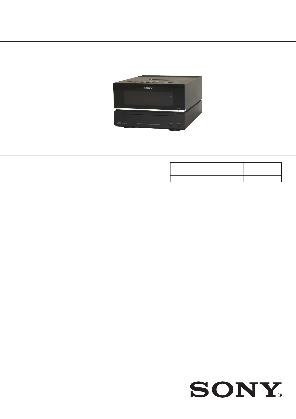
• HCD-BX20i is the amplifi er, CD player, tuner and
iPod section in CMT-BX20i.
• HCD-BX50BTi is the amplifi er, bluetooth, CD player,
tuner and iPod section in CMT-BX50BTi. Photo: HCD-BX20i
• e Bluetooth word mark and logos are owned by the Bluetooth SIG, Inc.
and any use of such marks by Sony Corporation is under license. Other
trademarks and trade names are those of their respective owners.
• MPEG Layer-3 audio coding technology and patents licensed from
Fraunhofer IIS and omson.
• iPod is a trademark of Apple Inc., registered in the U.S. and other countries.
SPECIFICATIONS
US Model
Canadian Model
HCD-BX20i/BX50BTi
Australian Model
Singapore Model
HCD-BX20i
Model Name Using Similar Mechanism HCD-BX5BT/EC68
Base Unit Name BU-K6BD90-WOD
Optical Pick-up Block Name KSM-213DCP
Mainunit
AUDIO POWER SPECIFICATIONS
POWER OUTPUT AND TOTAL HARMONIC DISTORTION:
(The United States model only)
With 6 ohm loads, both channels driven, from 120 – 10,000Hz; rated 25 watts
per channel minimum RMS power, with no more than 10% total harmonic
distortion from 250 milliwatts to rated output.
Amplifier section (BX20i)
DIN power output (rated):
18 + 18 W (6 ohms at 1 kHz, DIN)
Continuous RMS power output (reference): 25 + 25 W (6 ohms at 1 kHz,
10% THD)
Inputs
AUDIO IN (stereo mini jack): voltage 250 mV, impedance 47 kilohms
Outputs
PHONES (stereo mini jack): accepts headphones of 8 ohms or more
SPEAKER: accepts impedance of 6 to 16 ohms
Amplifier section (BX50BTi)
Continuous RMS power output (reference): 25 + 25 watts (6 ohms at
1 kHz, 10% THD)
Inputs
AUDIO IN (stereo mini jack): voltage250mV, impedance 47 kilohms
Outputs
PHONES (stereo mini jack): accepts headphones of 8 ohms or more
SPEAKER: accepts impedance of 6 ohms
Bluetooth section (BX50BTi)
Communication system: Bluetooth Standard version 2.0
Output: Bluetooth Standard Power Class 2
Maximum communication range: Line of sight approx. 10 m
Frequency band: 2.4 GHz band (2.4000 GHz – 2.4835GHz)
Modulation method: FHSS
Compatible Bluetooth profiles
A2DP (Advanced Audio Distribution Profile)
AVRCP (Audio Video Remote Control Profile)
Supported codecs:
Receive: SBC (Sub Band Codec), MP3
Transmit: SBC (Sub Band Codec)
1)
The actual range will vary depending on factors such as obstacles
between devices, magnetic filds around a microwave oven, static
electricity, reception sensitivity, antenna’s performance, operating
system, software application, etc.
2)
Bluetooth standard profiles indicate the purpose of Bluetooth
communication between devices.
CD player section
System: Compact disc and digital audio system
Laser Diode Properties
Emission Duration: Continuous
Laser Output*: Less than 44.6μW
This output is the value measurement at a distance of 200mm from the
*
objective lens surface on the Optical Pick-up Block with 7mm aperture.
Frequency response: 20 Hz – 20 kHz
Signal-to-noise ratio: More than 90 dB
Dynamic range: More than 90 dB
2)
:
1)
– Continued on next page –
9-889-020-02
2008C05-1
2008.03
©
COMPACT DISC RECEIVER
Sony Corporation
Audio Business Group
Published by Sony Techno Create Corporation
HCD-BX20i/BX50BTi
Ver. 1.1
Tunersection
FM stereo, FM/AM superheterodyne tuner
FM tuner section:
Tuning range:
orth American model: 87.5 – 108.0 MHz (100 kHz step)
N
Other models:87.5 – 108.0 MHz (50 kHz step)
Antenna: FM lead antenna
Antenna terminals: 75 ohms unbalanced
Intermediate frequency: 10.7 MHz
AM tuner section:
Tuning range:
NorthAmericanmodel:
530 – 1,710 kHz (with 10 kHz tuning interval)
531 – 1,710 kHz (with 9 kHz tuning interval)
Australian model:
531 – 1,710 kHz (with 9 kHz tuning interval)
530 – 1,710 kHz (with 10 kHz tuning interval)
Other models:
531 – 1,602 kHz (with 9 kHz tuning interval)
530 – 1,610 kHz (with 10 kHz tuning interval)
ntenna: AM loop antenna, external antenna terminal
A
Intermediate frequency: 450 kHz
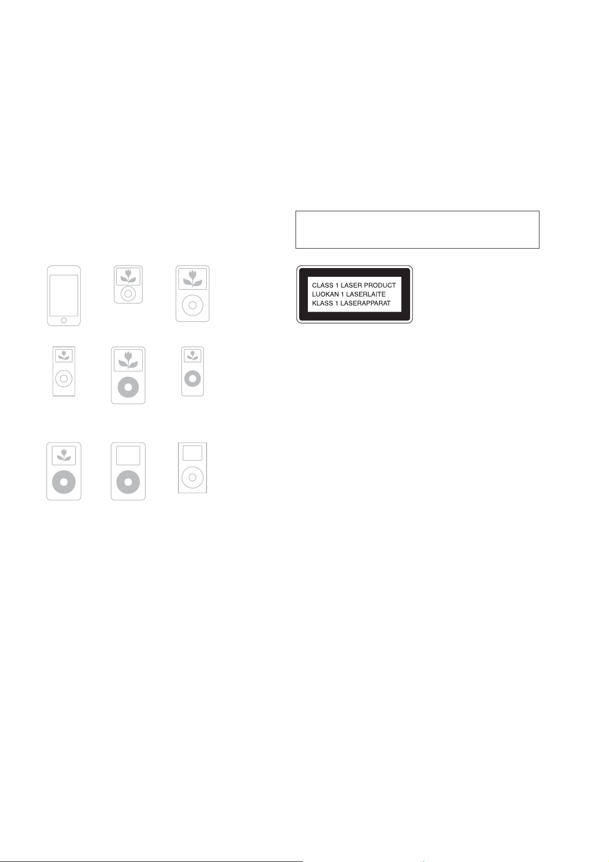
iPod section
Compatible iPod models:
iPod nano 3rd
generation
iPod touch
(video)
Notes on chip component replacement
• Never reuse a disconnected chip component.
• Notice that the minus side of a tantalum capacitor may be damaged by heat.
Flexible Circuit Board Repairing
• Keep the temperature of soldering iron around 270 °C during
repairing.
• Do not touch the soldering iron on the same conductor of the
circuit board (within 3 times).
• Be careful not to apply force on the conductor when soldering
or unsoldering.
CAUTION
Use of controls or adjustments or performance of procedures other than
those specifi ed herein may result in hazardous radiation exposure.
This appliance is classifi ed as a
CLASS 1 LASER product.
This marking is located on the
rear or bottom exterior.
iPod classic
iPod nano 2nd
generation
(aluminum)
iPod 4th
generation
iPod 5th
generation
(video)
iPod 4th
generation
iPod nano 1st
generation
iPod mini
(color display)
General
Power requirements:
North American model: 120 V AC, 60 Hz
Australian model: 230 – 240 V AC, 50/60 Hz
Other models: 120 V, 220 V, 230 – 240 V AC, 50/60 Hz, adjustable with
voltage selector
ower consumption: 63 watts
P
Dimensions (w/h/d) (excl. speakers): Approx. 215 × 140 × 298 mm
M
ass (excl. speakers):Approx. 3.9 kg
Design and specifications are subject to change without notice.
SAFETY-RELATED COMPONET WARNING!
COMPONENTS IDENTIFIED BY MARK 0 OR DOTTED LINE
WITH MARK 0 ON THE SCHEMATIC DIAGRAMS AND IN
THE PARTS LIST ARE CRITICAL TO SAFE OPERATION.
REPLACE THESE COMPONENTS WITH SONY PARTS
WHOSE PART NUMBERS APPEAR AS SHOWN IN THIS
MANUAL OR IN SUPPLEMENTS PUBLISHED BY SONY.
2
ATTENTION AU COMPOSANT AYANT RAPPORT
À LA SÉCURITÉ!
LES COMPOSANTS IDENTIFIÉS PAR UNE MARQUE 0 SUR
LES DIAGRAMMES SCHÉMATIQUES ET LA LISTE DES
PIÈCES SONT CRITIQUES POUR LA SÉCURITÉ DE FONCTIONNEMENT. NE REMPLACER CES COM- POSANTS QUE
PAR DES PIÈCES SONY DONT LES NUMÉROS SONT DONNÉS DANS CE MANUEL OU DANS LES SUPPLÉMENTS
PUBLIÉS PAR SONY.
After correcting the original service problem, perform the following safety check before releasing the set to the customer:
Check the antenna terminals, metal trim, “metallized” knobs,
screws, and all other exposed metal parts for AC leakage.
Check leakage as described below.
LEAKAGE TEST
The AC leakage from any exposed metal part to earth ground and
from all exposed metal parts to any exposed metal part having a
return to chassis, must not exceed 0.5 mA (500 microamperes.).
Leakage current can be measured by any one of three methods.
1. A commercial leakage tester, such as the Simpson 229 or RCA
WT-540A. Follow the manufacturers’ instructions to use these
instruments.
2. A battery-operated AC milliammeter. The Data Precision 245
digital multimeter is suitable for this job.
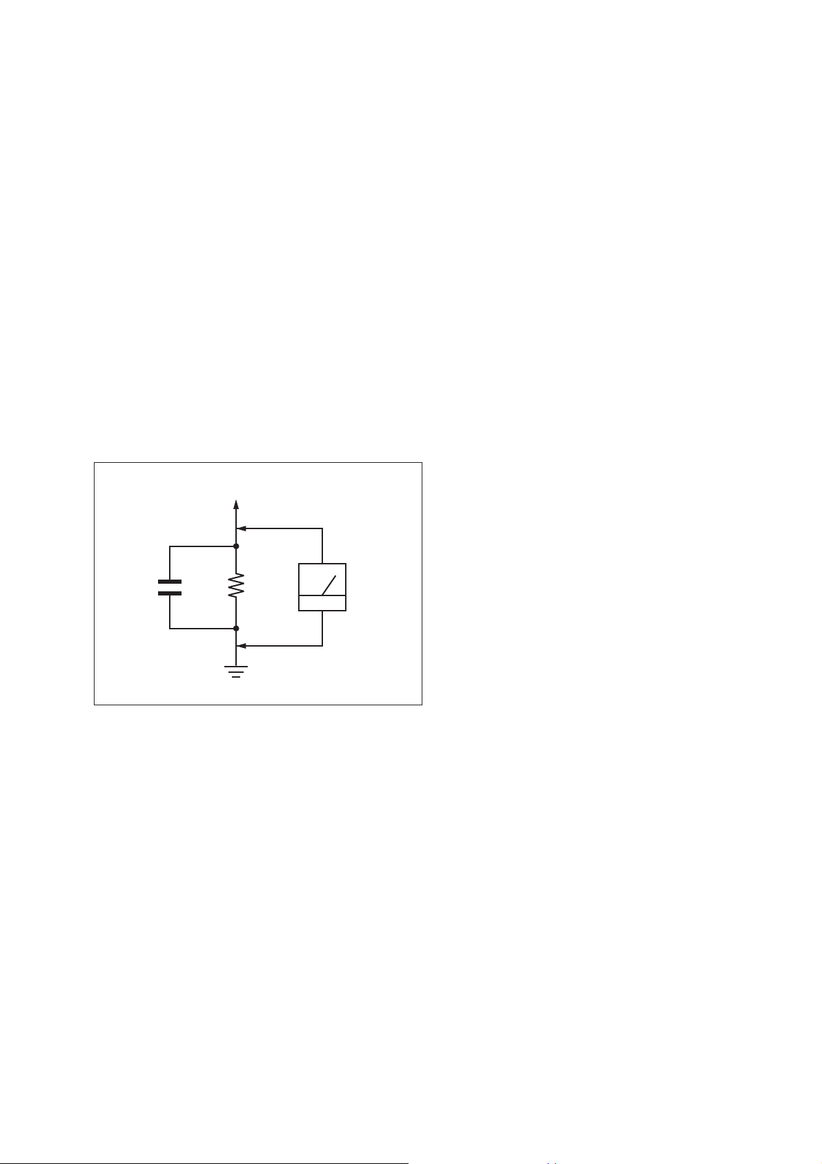
3. Measuring the voltage drop across a resistor by means of a
VOM or battery-operated AC voltmeter. The “limit” indication
is 0.75 V, so analog meters must have an accurate low-voltage
scale. The Simpson 250 and Sanwa SH-63Trd are examples
of a passive VOM that is suitable. Nearly all battery operated
digital multimeters that have a 2 V AC range are suitable. (See
Fig. A)
To Exposed Metal
Parts on Set
AC
1.5 kΩ0.15 μF
Earth Ground
Fig. A. Using an AC voltmeter to check AC leakage.
voltmeter
(0.75 V)
HCD-BX20i/BX50BTi
TABLE OF CONTENTSSAFETY CHECK-OUT
1. SERVICING NOTES ............................................. 4
2. GENERAL .................................................................. 6
3. DISASSEMBLY
3-1. Disassembly Flow ........................................................... 10
3-2. Panel (Side L/R) .............................................................. 11
3-3. Top Panel Block .............................................................. 11
3-4. TOP KEY Board, IP Board, Panel Top (IP) .................... 12
3-5. Front Panel Block ........................................................... 12
3-6. Rear Panel Block ............................................................ 13
3-7. Panel (Rear) .................................................................... 13
3-8. AMP Board Block ........................................................... 14
3-9. POWER Board Block ..................................................... 14
3-10. MAIN Board ................................................................... 15
3-11. Loading Mechanism Block ............................................. 15
3-12. Base Unit ......................................................................... 16
3-13. Belt .................................................................................. 16
3-14. OP Base Assy (KSM-213D) ........................................... 17
4. TEST MODE ............................................................ 18
5. ELECTRICAL CHECKS ...................................... 20
6. DIAGRAMS
6-1. Block Diagram - CD SERVO Section - .......................... 21
6-2. Block Diagram
- iPod, TUNER, BLUETOOTH Section - ...................... 22
6-3. Block Diagram - MAIN Section - ................................... 23
6-4. Block Diagram
- PANEL, POWER SUPPLY Section - ........................... 24
6-5. Printed Wiring Boards - CD Section - ............................ 26
6-6. Schematic Diagram - CD Board - ................................... 27
6-7. Printed Wiring Boards - BLUETOOTH Section - .......... 28
6-8. Schematic Diagram - BLUETOOTH Section - .............. 29
6-9. Printed Wiring Board - IP Board - .................................. 30
6-10. Schematic Diagram - IP Board - ..................................... 31
6-11. Printed Wiring Boards - MAIN Section - ....................... 32
6-12. Schematic Diagram - MAIN Section (1/3) - ................... 33
6-13. Schematic Diagram - MAIN Section (2/3) - ................... 34
6-14. Schematic Diagram - MAIN Section (3/3) - ................... 35
6-15. Printed Wiring Boards
- HEADPHONE/AMP Section - ..................................... 36
6-16. Schematic Diagram - HEADPHONE/AMP Section - .... 37
6-17. Printed Wiring Boards - PANEL Section - ..................... 38
6-18. Schematic Diagram - PANEL Section - .......................... 39
6-19. Printed Wiring Board - POWER Board - ........................ 40
6-20. Schematic Diagram - POWER Board - .......................... 41
7. EXPLODED VIEWS
7-1. Panel Section ................................................................... 50
7-2. Top Panel Section ........................................................... 51
7-3. Front Panel Section ......................................................... 52
7-4. MAIN Board Section ...................................................... 53
7-5. POWER Board Section ................................................... 54
7-6. Loading Mechanism Section .......................................... 55
7-7. Base Unit Section (BU-K6BD90-WOD) ....................... 56
8. ELECTRICAL PARTS LIST .............................. 57
3
HCD-BX20i/BX50BTi
Ver. 1.1
SECTION 1
SERVICING NOTES
NOTES ON HANDLING THE OPTICAL PICK-UP
BLOCK OR BASE UNIT
The laser diode in the optical pick-up block may suffer electrostatic break-down because of the potential difference generated by the
charged electrostatic load, etc. on clothing and the human body.
During repair, pay attention to electrostatic break-down and also
use the procedure in the printed matter which is included in the
repair parts.
The fl exible board is easily damaged and should be handled with
care.
NOTES ON LASER DIODE EMISSION CHECK
The laser beam on this model is concentrated so as to be focused
on the disc refl ective surface by the objective lens in the optical
pickup block. Therefore, when checking the laser diode emission,
observe from more than 30 cm away from the objective lens.
UNLEADED SOLDER
Boards requiring use of unleaded solder are printed with the leadfree mark (LF) indicating the solder contains no lead.
(Caution: Some printed circuit boards may not come printed with
the lead free mark due to their particular size)
: LEAD FREE MARK
Unleaded solder has the following characteristics.
• Unleaded solder melts at a temperature about 40 °C higher
than ordinary solder.
Ordinary soldering irons can be used but the iron tip has to be
applied to the solder joint for a slightly longer time.
Soldering irons using a temperature regulator should be set to
about 350 °C.
Caution: The printed pattern (copper foil) may peel away if the
heated tip is applied for too long, so be careful!
• Strong viscosity
Unleaded solder is more viscous (sticky, less prone to fl ow)
than ordinary solder so use caution not to let solder bridges
occur such as on IC pins, etc.
• Usable with ordinary solder
It is best to use only unleaded solder but unleaded solder may
also be added to ordinary solder.
ANTITHEFT UNLOCK MODE
Procedure:
1. Press the [
] button to turn the power on.
?/1
2. Press the [FUNCTION] button to select “CD”.
3. Press two buttons of [
x/CANCEL
] and [
] for 5 seconds.
A
4. The message “UNLOCKED” is displayed on the fl uorescent
indicator tube and the disc tray is unlocked.
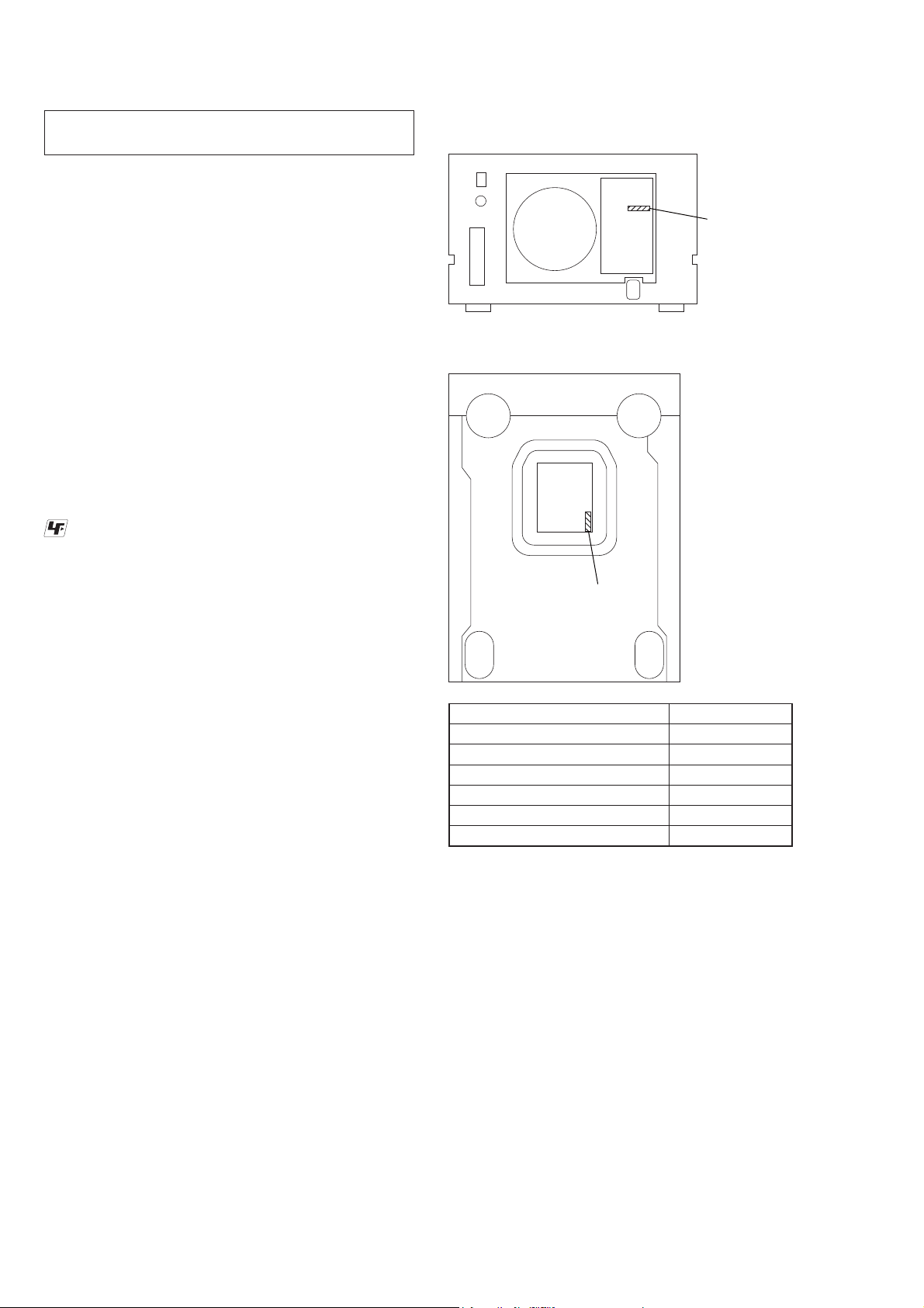
MODEL IDENTIFICATION
– Rear View – (Except Singapore model)
– Bottom View – (Singapore model)
Part No.
Model Part No.
HCD-BX20i: US model
HCD-BX20i: Canadian model
HCD-BX50BTi: US model
HCD-BX50BTi: Canadian model
HCD-BX20i: Australian model
HCD-BX20i: Singapore model
3-293-462-0[]
3-293-463-0[]
3-293-464-0[]
3-293-465-0[]
3-295-838-0[]
3-296-979-0[]
Part No.
Note: When “LOCKED” is displayed, the tray lock is not released by
turning power on/off with the [?/1] button.
NOTE OF REPLACING THE IC904 ON THE BT BOARD
IC904 on the BT board cannot exchange with single. When IC904
on the BT board is damaged, exchange the entire mounted board.
4
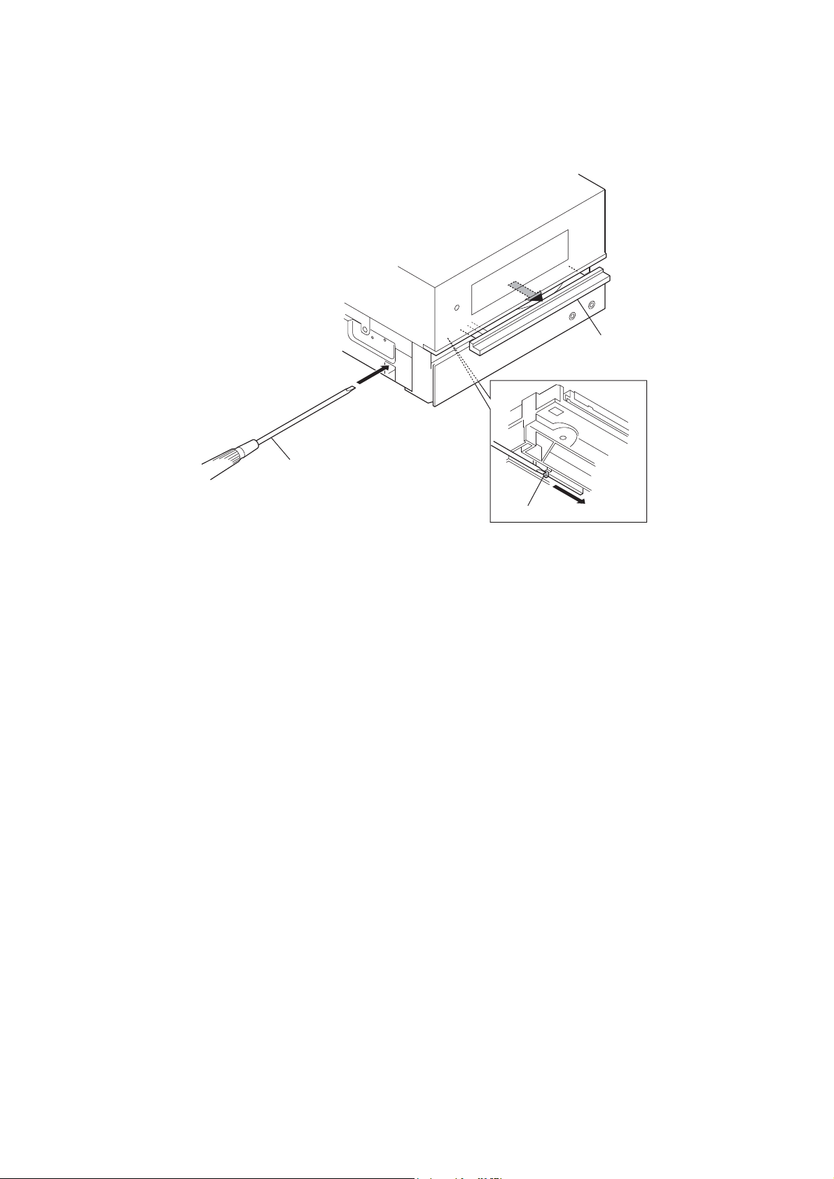
HOW TO OPEN THE TRAY WHEN POWER SWITCH TURN OFF
Note: Please insert a screwdriver after removing the panel (side L).
About disassembly of the panel (side L), please refer to “3-2. Panel (Side L/R)” (page 13).
HCD-BX20i/BX50BTi
Open the tray.
Insert the driver.
Push the boss.
5
HCD-BX20i/BX50BTi
HCD-BX20i
Basic Operations
SECTION 2
GENERAL
Adjusting the sound
To adjust the volume
Press VOLUME +/ (or VOL +/ on the unit) .
To add a sound eect
To Press
Generate a more dynamic
sound (Dynamic Sound
Generator X-tra)
Set the sound eect
on the unit.
DSGX
repeatedly to select
EQ
“BASS” or “TREBLE,” and
then press +/
to adjust the level.
repeatedly
Listening to the radio
1 Select “TUNER FM” or “TUNER AM.”
Press FUNCTION +/ (or FUNCTION on the unit)
repeatedly.
2 Select the tuning mode.
Press TUNING MODE
appears.
3 Tune in the desired station.
Press +/ (or TUNE +/ on the unit)
stops automatically when a station is tuned in, and
then “TUNED” and “STEREO” (for stereo programs
only) appear.
repeatedly until “AUTO”
. Scanning
This section is extracted
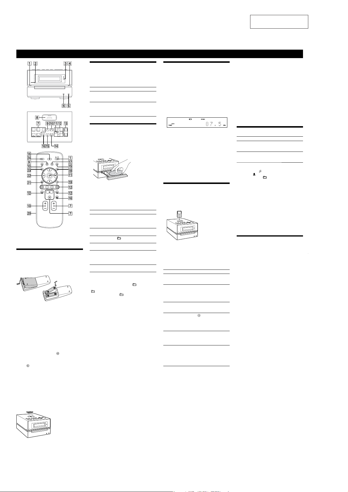
from instruction manual.
Notes
When placing or removing the iPod, handle the iPod in the same
angle as that of the iPod connector
or sway the iPod to prevent connector damage.
Do not carry the unit with an iPod set on the connector. Doing so
may cause a malfunction.
When placing or removing the iPod, brace the unit with one hand
and take care not to press the controls of the iPod by mistake.
To remove the iPod Dock Adaptor, pull it up with your ngernail or
a at object using the slot inside the adaptor.
Before disconnecting the iPod, pause playback.
While playing video, you cannot use /
rewind (fast forward) by holding down /
To change the volume level, use VOLUME +/ (or VOL +/ on the
unit)
. e volume level does not change even if adjusted on the
iPod.
is system is designed for iPod only. You cannot connect any other
portable audio players.
To use an iPod, refer to the user’s guide of your iPod.
Sony cannot accept responsibility in the event that data recorded to
iPod is lost or damaged when using an iPod with this unit.
on the unit and do not twist
. You can fast
.
is manual mainly explains operations using the
remote, but the same operations can also be performed
using the buttons on the unit having the same or similar
names.
Before using the system
To use the remote
Slide and remove the battery compartment lid , and
insert the two supplied R6 (size AA) batteries, side
rst, matching the polarities shown below.
Notes on using the remote
With normal use, the batteries should last for about six months.
Do not mix an old battery with a new one or mix dierent types of
batteries.
If you do not use the remote for a long period of time, remove the
batteries to avoid damage from battery leakage and corrosion.
To set the clock
Use buttons on the remote to set the clock.
1 Turn on the system.
Press (power)
2 Select the clock set mode.
Press TIMER MENU
on the display, press /
“CLOCK SET?” and then press
3 Set the time.
Press /
press
minutes.
e clock settings are lost when you disconnect the
power cord or if a power failure occurs.
To display the clock when the system is o, press
DISPLAY
seconds.
To use the iPod
Insert an iPod Dock Adaptor into the unit’s connector
before use.
For details on the supplied iPod Dock Adaptors, refer to
the instructions supplied with the Dock Adaptors.
.
. If the current mode appears
repeatedly to select
(enter) .
repeatedly to set the hour, and then
(enter) . Use the same procedure to set the
. e clock is displayed for about 8
Playing a CD/MP3 disc
1 Select the CD function.
Press FUNCTION +/ (or FUNCTION on the unit)
repeatedly.
2 Place a disc.
Press (open/close)
with the label side up on the disc tray.
To close the disc tray, press (open/close) on the
unit.
Do not force the disc tray closed with your nger, as
this may damage the unit.
3 Start playback.
Press (play) (or CD (play/pause) on the
unit)
To Press
Pause playb ack
Stop playback
Select a folder on an
MP3 disc
Select a track or le
Find a point in a
track or le
Select Repeat Play
To change the play mode
Press PLAY MODE repeatedly while
stopped. You can select normal play (“
les in the folder on the disc), shue play (“SHUF” or
SHUF*”), or program play (“PGM”).
“
* When playing a CD-DA disc, (SHUF) Play performs the same
operation as normal (shue) play.
Notes on Repeat Play
All tracks or les on a disc are played repeatedly up to ve times.
“REP1” indicates that a single track or le is repeated until you stop
it.
Notes on playing MP3 discs
Do not save other types of tracks or les or unnecessary folders on a
disc that has MP3 les.
Folders that have no MP3 les are skipped.
MP3 les are played back in the order that they are recorded onto
the disc.
e system can only play MP3 les that have a le extension of
“.MP3”.
If there are les on the disc that have the “.MP3” le extension,
but that are not MP3 les, the unit may produce noise or may
malfunction.
e maximum number of:
folders is 255 (including the root folder).
MP3 les is 511.
MP3 les and folders that can be contained on a single disc is 512.
folder levels (the tree structure of les) is 8.
Compatibility with all MP3 encoding/writing soware, recording
device, and recording media cannot be guaranteed. Incompatible
MP3 discs may produce noise or interrupted audio or may not play
at all.
Notes on playing multisession discs
If the disc begins with a CD-DA (or MP3) session, it is recognized as
a CD-DA (or MP3) disc, and other sessions are not played back.
A disc with a mixed CD format is recognized as a CD-DA (audio)
disc.
on the unit, and place a disc
.
(pause) (or CD (play/
pause) on the unit)
To resume play, press the button
again.
(stop) (or /CANCEL on the
unit)
+/ (select folder) .
/
.
Hold down / (rewind/
fast forward)
and release the button at the
desired point.
REPEAT
“REP” or “REP1” appears.
.
(go back/go forward)
.
during playback,
repeatedly until
the player is
”
for all MP3
To stop automatic scanning
Press (stop) (or /CANCEL on the unit) .
To tune in a station with a weak signal
If “TUNED” does not appear and the scanning does not
stop, press TUNING MODE
and “PRESET” disappear, and then press +/ (or TUNE
+/ on the unit)
station.
To reduce static noise on a weak FM stereo
station
Press FM MODE repeatedly until “MONO” appears
to turn o stereo reception.
repeatedly until “AUTO”
repeatedly to tune in the desired
Playing the iPod
1 Select the iPod function.
Press FUNCTION +/ (or FUNCTION on the unit)
repeatedly.
2 Place the iPod.
3 Start playback.
Press (play) (or iPod (play/pause) on the
.
unit)
To control the iPod
You can control your iPod with the following buttons on
the remote or unit.
To Pr es s
Pause playb ack
Scroll up/down the
iPod menus
Select a track
or chapter of
audiobook/podcast
Choose the selected
item
Find a point in a
track or chapter of
audiobook/podcast
Return to the
previous menu or
select a menu
To use the system as a battery charger
You can use the system as a battery charger for the iPod
when the system is both on and o.
e charging begins when the iPod is placed on the unit’s
connector
display. For details, see the user’s guide of your iPod.
To stop charging the iPod
Remove the iPod. If you stop charging the iPod when
the system is o, press DISPLAY
disappears in the display.
(pause) (or iPod
(play/pause) on the unit)
.
(stop)
. You can scroll up or
/
down the iPod menus much like
the Click Wheel operations of
the iPod or the drag up-or-down
operations of the iPod touch.
(go back/go forward)
/
. To fast-forward or fast-
rewind, hold down the button.
/ (enter) (or ENTER on
. You can choose the
the unit)
selecte d item much like t he center
button on the iPod or the touch
operation of the iPod touch.
(fast rewind/fast
/
during playback, and
forward)
release the button at the desired
point.
/TOOL MENU /
(return) . You can return to the
previous menu or select a menu
much like the Menu button on
the iPod or the touch operation
of the iPod touch.
. e charging status appears in the iPod
until the clock
or
Changing the display
To Pr es s
Change
information on the
display
Check the clock
when the system
2)
is o
1)
For example, you can view CD/MP3 disc information, such as;
track or le number during normal play.
track or le name (“
artist name (“
album or folder name (“
total playing time while the player is stopped.
2)
e clock is displayed continuously while the iPod is being charged.
To turn o the clock display, press DISPLAY
charging the iPod”).
3)
e STANDBY indicator on the unit lights up when the system is
o.
Notes on the display information
Characters that cannot be displayed appear as “_”.
e following are not displayed:
total playing time for a CD-DA disc depending on the play mode.
total playing time and remaining playing time for an MP3 disc.
e following are not displayed correctly:
folder and le names that do not follow either ISO9660 Level 1,
Level 2 or Joliet in the expansion format.
e following is displayed:
ID3 tag information for MP3 les when ID3 version 1 and version
2 tags are used (up to 62 characters).
DISPLAY repeatedly when the
system is on.
1)
DISPLAY when the system is
o
seconds.
”) during normal play.
”) during normal play.
3)
. e clock is displayed for 8
”) during normal play.
(See “To stop
Using optional audio components
To connect an optional headphones
Connect headphones to the PHONES jack on the
unit.
To connect an optional component
Connect additional audio component to the AUDIO
on the unit using an audio analog cord (not
IN jack
supplied). Turn down the volume on the system, and
then select the AUDIO IN function.
6
Other Operations
HCD-BX20i/BX50BTi
Creating your own program
(Program Play)
1 Press FUNCTION +/ (or FUNCTION on the unit)
repeatedly to select the CD function.
2 Press PLAY MODE
while the player is stopped.
3 Press /
track or le number appears.
When programming les, press
to select the desired folder, and then select the desired
le.
4 Press (or ENTER on the unit)
or le to the program.
“.” appears when the total program time
exceeds 100 minutes for a CD, or when you select a
CD track whose number is 21 or over, or when you
select an MP3 le.
5 Repeat steps 3 through 4 to program additional
tracks or les, up to a total of 25 tracks or les.
6 To play your program of tracks or les, press (or
CD on the unit)
e program remains available until you open the disc
tray. To play the same program again, press (or
CD on the unit)
To cancel Program Play
Press PLAY MODE repeatedly until “PGM”
disappears while the player is stopped.
To delete the last track or le of the program
Press CLEAR while the player is stopped.
repeatedly until “PGM” appears
repeatedly until the desired
Selected track or le
number
.
.
+/ repeatedly
Total playing time of program
(including selected track
or le)
to add the track
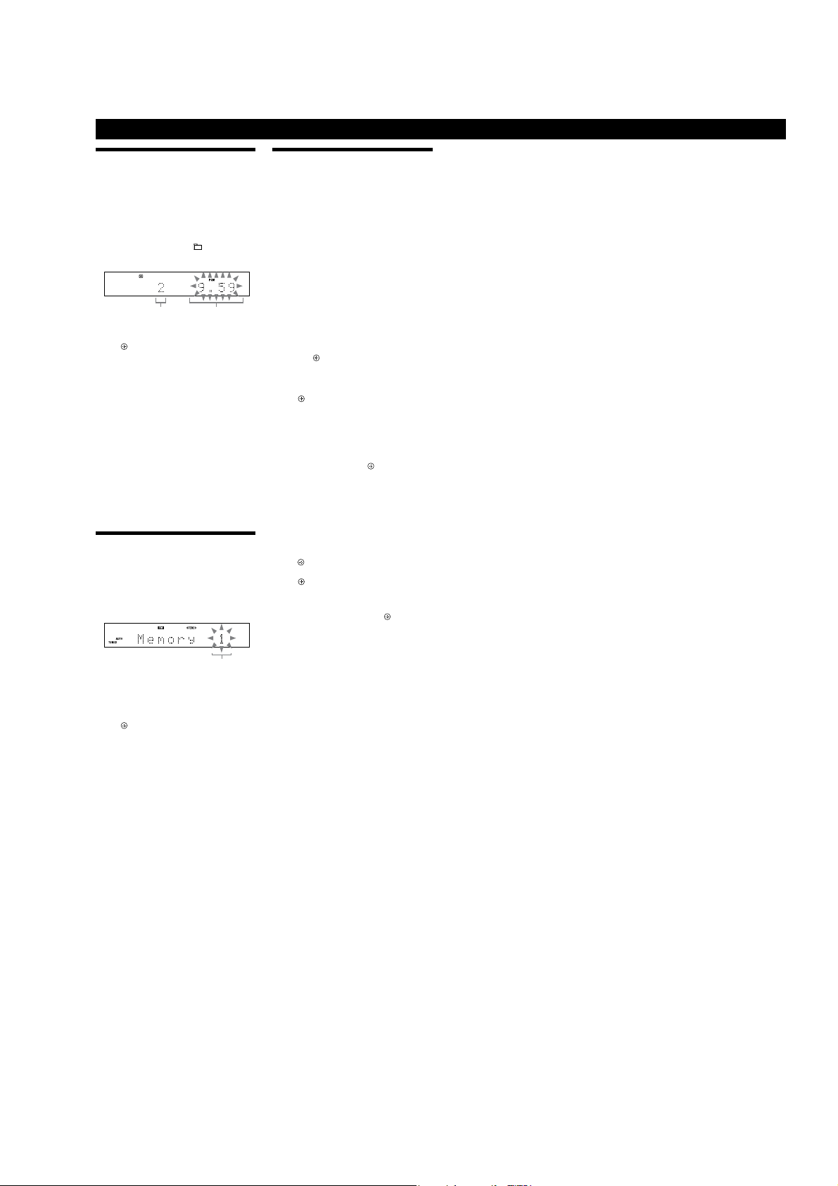
Presetting radio stations
You can preset your favorite radio stations and tune
them in instantly by selecting the corresponding preset
number.
Use buttons on the remote to preset stations.
1 Tune in the desired station (See “Listening to the
radio”).
2 Press TUNER MEMORY
3 Press +/
preset number.
If another station is already assigned to the selected
preset number, the station is replaced by the new
stations.
4 Press
5 Repeat steps 1 through 4 to store other stations.
You can preset up to 20 FM and 10 AM stations. e
preset stations are retained for about half a day even
if you disconnect the power cord or if a power failure
occurs.
6 To call up a preset radio station, press TUNING
MODE
then press +/
preset number.
.
Preset number
repeatedly to select your desired
.
repeatedly until “PRESET” appears, and
repeatedly to select the desired
Using the Timers
e system oers two timer functions. If you use the Play
Timer with the Sleep Timer, the Sleep Timer has priority.
Use buttons on the remote to use the timer functions.
Sleep Timer:
You can fall asleep to music. is function works even if
the clock is not set.
Press SLEEP
system automatically turns o aer the current disc stops
or in 100 minutes.
Play Timer:
You can wake up to CD, tuner or iPod at a preset time.
Make sure you have set the clock.
1 Prepare the sound source.
2 Press TIMER MENU
3 Press
4 Set the time to start playback.
5 Use the same procedure as in step 4 to set the time
6 Select the sound source.
7 Press
To activate or check the timer again
1 Press TIMER MENU
2 Press
3 Press
To cancel the timer
Repeat the same procedure as above until “TIMER
OFF?” appears in step 3, and then press
To change the setting
Start over from step 1.
Note on the iPod touch user
e Play Timer may not be activated depending on the status of the
connected iPod touch.
Tip
e Play Timer setting remains as long as the setting is not canceled
manually.
repeatedly. If you select “AUTO,” the
Prepare the sound source, and then press VOLUME
+/
to adjust the volume.
To start from a specic track or le, create your own
program.
then press
“ON” appears, and the hour indication ashes.
Press /
press
e minute indication ashes. Use the procedure
above to set the minutes.
to stop playback.
Press /
source appears, and then press
shows the timer settings.
e system turns on 15 seconds before the preset time.
If the system is on at the preset time, the Play Timer
will not play.
“TIMER SEL?” ashes in the display.
press
.
repeatedly to select “PLAY SET?,” and
/
.
repeatedly to set the hour, and then
.
repeatedly until the desired sound
to turn o the system.
.
.
repeatedly to select “PLAY SEL?,” then
/
.
. e display
.
7
HCD-BX20i/BX50BTi
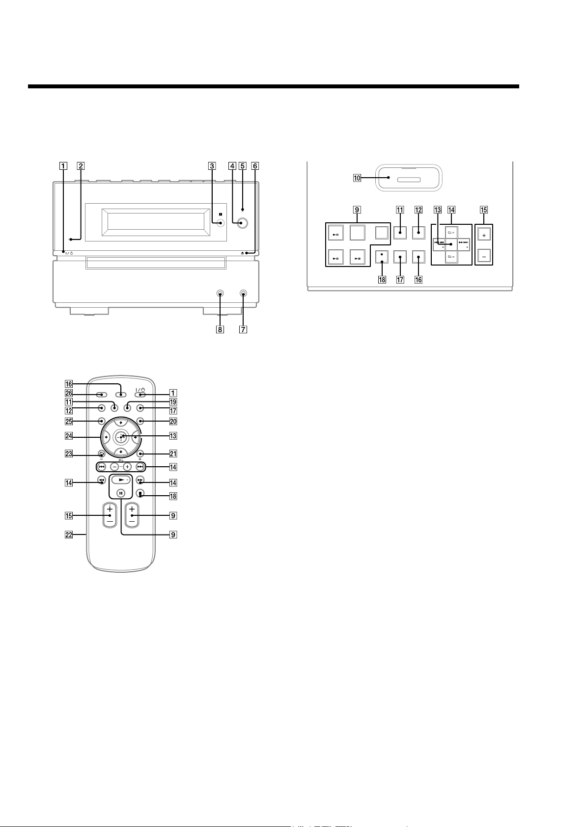
HCD-BX50BTi
Guide to parts and controls
This manual mainly explains operations using the remote, but the same operations can also be performed using the buttons on the unit having the same or similar names.
Unit (HCD-BX50BTi/Compact Disc Receiver)
Front panel
Top panel
Remote (RM-AMU009)
/ (power) button
Presstoturnonthe system.
STANDBY indicator
Lights up when the system is turned off.
Remote sensor
BLUETOOTH button
Press to make a connection,
disconnection, or pairing with a
Bluetooth device.
BLUETOOTH indicator
Lights up when the Bluetooth function
is active.
; (open/close) button
Presstoopenorclosethe disctray.
AUDIO IN jack
Connect to an optional audio
component.
PHONES jack
Connect the headphones.
Playback buttons and function
buttons
Unit: BLUETOOTH V (play/
pause) button
Press to select the Bluetooth function.
Presstostartorpauseplaybackofthe
music on the Bluetooth device (Bluetooth
mobile phone, etc.).
8

HCD-BX20i/BX50BTi
Unit: CD V (play/pause)
button
Press to select the CD function.
Presstostartorpauseplaybackof a disc.
Unit: iPod V (play/pause)
button
Presstoselectthe iPodfunction.
Presstostartorpauseplaybackofthe
iPod.
Remote: / (play) button,
9(pause) button
Presstostartorpauseplayback.
TUNER/BAND button
Press to select the TUNER function.
Press to select FM or AM reception
mode.
Unit: FUNCTION button
Remote: FUNCTION +/– button
Presstoselectthefunction.
R
iPod connector
Place an iPod on the connector to listen
to audio contents stored in the iPod.
RB
REPEAT/FM MODE button
Press to listen to a disc, a single track or
file repeatedly.
Presstoselectthe FM receptionmode
(monaural or stereo).
RT
PLAY MODE/TUNING MODE
button
Press to select the play mode of a CD or
MP3 disc.
Press to select the tuning mode.
RE
Unit: ENTER button
Remote:
Press to enter the settings.
(enter) button
RG
/ (go back/go forward)
button
Press to select a track or file.
Unit: TUNE +/– (tuning) button
Remote: +/– (tuning) button
Press to tune in the desired station.
+/– (select folder) button
Press to select a folder.
RH
Unit: VOL +/– button
Remote: VOLUME +/– button
Press to adjust the volume.
RI
DISPLAY button
Presstochangethe informationonthe
display.
RK
Sound buttons
Unit: DSGX button
Remote: EQ button
Press to select the sound effect.
RL
Unit:Y/CANCEL (stop/cancel)
button
Remote: Y (stop) button
Press to stop playback.
RM
CLEAR button
Press to delete a pre-programmed track
or file.
Press to erase the pairing registration
information of the Bluetooth device.
X
TIMER MENU button
Press to set the clock and the Play Timer.
XB
TOOL MENU button
Press to select a menu when using the
iPod.
XT
Battery compartment lid
XE
0 RETURN button
Presstoreturntothepreviousmenu
when using the iPod.
XG
7/W/ #/ C button
Presstoselectthemenuitems.
XH
TUNER MEMORY button
Press to preset the radio station.
XI
SLEEP button
Press to set the Sleep Timer.
Setting the clock
Usebuttonsontheremotetosetthe
clock.
1
Press / to turn on the
system.
2
Press TIMER MENU X.
The hour indication flashes in the
display.
If “PLAY SET?” flashes in the display,
press 7/WXGrepeatedly to select
“CLOCK SET?” and then press
3
Press 7/WXG repeatedly to set
the hour, and then press
4
Use the same procedure to set
the minutes.
The clock setting are lost when you
disconnect the power cord or if a
power failure occurs.
To display the clock when the system
is off
Press DISPLAY RI. The clock is displayed
for about 8 seconds.
RE
RE
.
.
N/. (rewind/fast forward)
button
Press to find a point in a track or file.
9
HCD-BX20i/BX50BTi
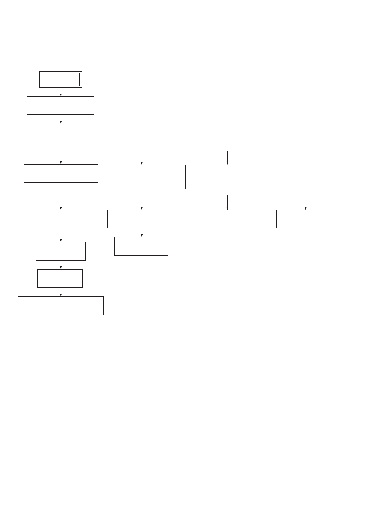
DISASSEMBLY
• This set can be disassembled in the order shown below.
3-1. DISASSEMBLY FLOW
SET
3-2. PANEL (SIDE L/R)
(Page 11)
3-3. TOP PANEL BLOCK
(Page 11)
SECTION 3
3-5. FRONT PANEL BLOCK
(Page 12)
3-11. LOADING MECHANISM
BLOCK
(Page 15)
3-12. BASE UNIT
(Page 16)
3-13. BELT
(Page 16)
3-14. OP BASE ASSY (KSM-213D)
(Page 17)
3-6. REAR PANEL BLOCK
(Page 13)
3-8. AMP BOARD BLOCK
(Page 14)
3-10. MAIN BOARD
(Page 15)
3-4. TOP KEY BOARD,
IP BOARD, PANEL TOP (IP)
(Page 12)
3-9. POWER BOARD BLOCK
(Page 14)
3-7. PANEL (REAR)
(Page 13)
10

Note: Follow the disassembly procedure in the numerical order given.
3-2. PANEL (SIDE L/R)
screw
(BVTP3 × 10)
panel (side L)
two screws
(BVST3 × 6 (BX20i: US, Canadian/BX50BTi)
/BVTT3 × 6 (BX20i: Australian, Singapore))
HCD-BX20i/BX50BTi
Ver. 1.1
screw
(BVTP3 × 10)
panel (side R)
two screws
(BVST3 × 6 (BX20i: US, Canadian/BX50BTi)
/BVTT3 × 6 (BX20i: Australian, Singapore))
3-3. TOP PANEL BLOCK
two screws
(BVTT3 × 6)
top panel block
connector
(CN325)
connector
(CN322)
five screws
(BVTP3 × 10)
two screws
(BVTT3 × 6)
11
HCD-BX20i/BX50BTi
Ver. 1.1
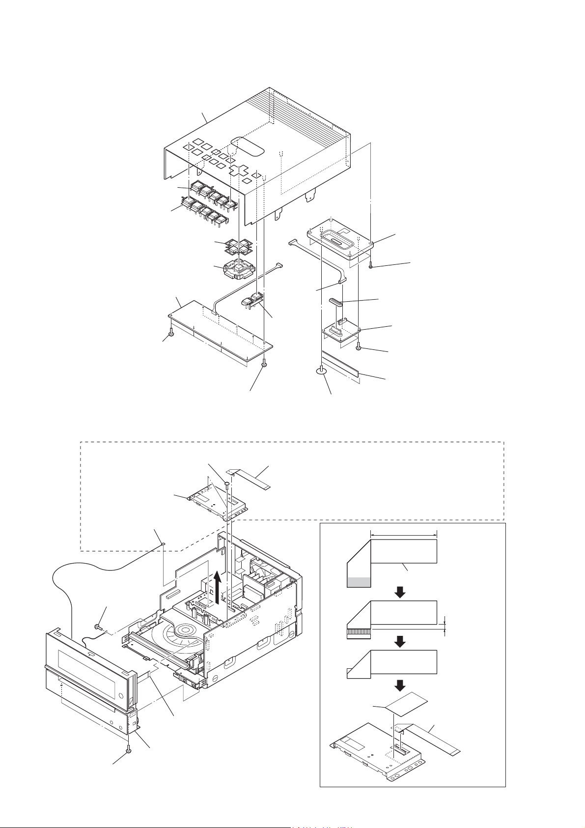
3-4. TOP KEY BOARD, IP BOARD, PANEL TOP (IP)
panel top (IP)
RI
button (function)
button (function B)
button (tune)
button (enter)
TOP KEY board
RT
(CN101)
connector
base (IP) assy
RH
escutcheon
RB
four screws
RG
(BVTP2.6 )
four screws
(BVTP2.6)
3-5. FRONT PANEL BLOCK
(BX50BTi only)
shield case (lid)
screw
(BVTT3 × 6)
connector
(BVTP3 × 8)
two screws
five screws
(BVTP2.6)
button
(VOL)
two screws
(2.6 × 10)
flexible flat cable (15 core)
(BT board: CN901/MAIN board: CN323)
Note: When exchanging or removing flexible flat cable
between the BT substrate and the MAIN substrate,
please be sure to bend flexible flat cable as follows
and install it in shield case (lid) using the tape installed
from origin.
IP board
RE
four screws
(PTP2 × 5)
HOLD board
60mm ±2mm
flexible flat cable (15 core)
12
flexible flat cable (13 core)
(CN306)
front panel block
two screws
(BVST3 × 6 (BX20i: US, Canadian/BX50BTi)
/BVTT3 × 6 (BX20i: Australian, Singapore))
tape
60mm ±2mm
flexible flat cable
(15 core)

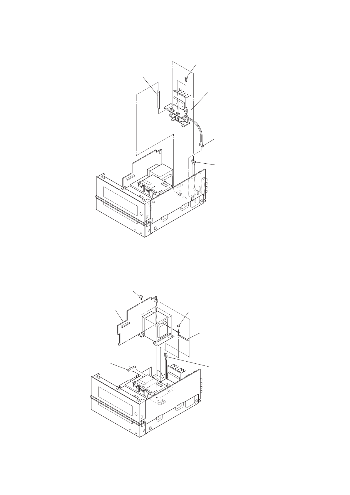
3-6. REAR PANEL BLOCK
(BX20i: Singapore model)
connector (CN902)
connector (CN905)
rear panel block
connector (CN313)
HCD-BX20i/BX50BTi
flexible flat cable (9 core)
(CN310)
two screws
(B3)
three screws
(BVST3 × 6: Australian, Singapore
/BVTT3 × 6: US, Canadian)
Ver. 1.1
3-7. PANEL (REAR)
(BX20i: Singapore model)
VOL SELECT board
two screws
(BVTP2.6)
(M901)
D.C. fan
panel (rear)
two screws
(BVTP3 × 16)
plate
(GND TU)
two screws
(BVST3 × 6: Australian, Singapore
/BVTT3 × 6: US, Canadian)
flexible flat cable (9 core)
tuner (FM/AM)
two feet (felt)
13
HCD-BX20i/BX50BTi
3-8. AMP BOARD BLOCK
flexible flat cable (7 core)
(AMP board: CN308/MAIN board: CN309)
two screws
(BV3)
AMP board block
connector (CN312)
connector (CN320)
3-9. POWER BOARD BLOCK
POWER board block
connector (CN904)
four screws
screw
(BV3)
coating clip
connector (CN901)
14
3-10. MAIN BOARD
two screws
(BVTT3 × 6)
connector
(CN316)
connector
(CN303)
MAIN board
HCD-BX20i/BX50BTi
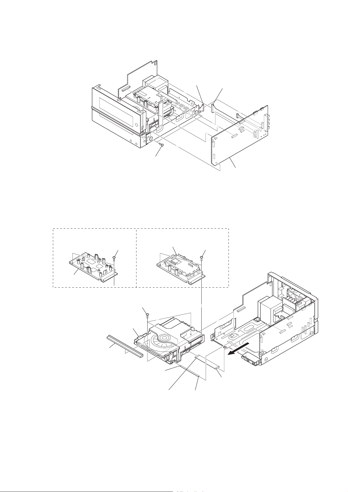
3-11. LOADING MECHANISM BLOCK
(BX50BTi)(BX20i)
two screws
holder (CD)
(BVTP3 × 8)
three screws
(BV3)
loading mechanism block
door CD
flexible flat cable (5 core)
(CN001)
flexible flat cable (21 core)
(CD board: CN201)
BT board block
two screws
(BVTP3 × 8)
flexible flat cable (21 core)
(MAIN Board: CN305)
flexible flat cable (5 core)
(CN311)
15
HCD-BX20i/BX50BTi
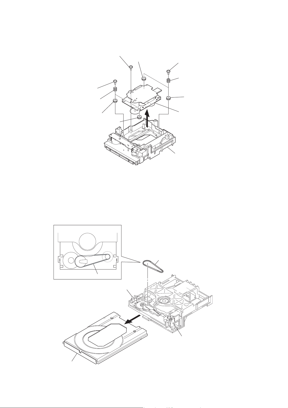
3-12. BASE UNIT
two floating screws
two springs (insulator)
floating screw
insulator
two floating screws
two springs
(insulator)
insulator
3-13. BELT
position of belt
insulator
insulator
– Bottom view –
base unit
loading (BK) assy
tray (AU)
belt
belt
claw
claw
16

3-14. OP BASE ASSY (KSM-213D)
HCD-BX20i/BX50BTi
op base assy
(KSM-213D)
flexible flat cable (16 core)
(CN301)
CD board
Remove four solders.
17

HCD-BX20i/BX50BTi
SECTION 4
TEST MODE
COLD RESET
The cold reset clears all data including preset data stored in the
RAM to initial conditions. Execute this mode when returning the
set to the customer.
Procedure:
1. Press three buttons of [x/CANCEL], [VOL +] and [?/1] simultaneously.
2. The system is reset and becomes standby states.
COMMON TEST MODE
This mode is used to check operations of amplifi er.
Procedure
1. Press the [
2. Press three buttons of [TUNER/BAND], [x/CANCEL] and
[ENTER] simultaneously.
3. When the COMMON test mode is activated, “AUDIO IN” is
displayed on the liquid crystal display and “cPLAY SLEEP”
blink on the fl uorescent indicator tube.
4. Each time [EQ] button on the remote commander is pressed,
the display changes starting “TONE MAX”, “TONE MIN”
and “TONE FLAT” this order.
5. Press the [VOL –] button, “VOLUME MIN” is displayed
on the fl uorescent indicator tube. Press the [VOL +] button,
“VOLUME MAX” is displayed on the fl uorescent indicator
tube.
6. To release this mode, press the [
PANEL TEST MODE
This mode is used to check the liquid crystal display, LED, model,
destination, software version and key.
Procedure
1. Press the [?/1] button to turn the power on.
2. Press three buttons of [TUNER/BAND], [DSGX] and [ENTER] simultaneously.
3. All segments on the fl uorescent indicator tube, [STANDBY]
LED and [BLUETOOTH OPR] LED (BX50BTi only) light
up.
4. Press the [ENTER] button, the model and destination are alternately displayed on the fl uorescent indicator tube.
5. Press the [ENTER] button again, MC version is displayed on
the fl uorescent indicator tube.
6. Each time [ENTER] button is pressed, the display changes
starting from MC version, GC version, BT version (BX50BTi
only), CLA version, CD version, CDD version, CDMA version, CDMB version, BDA version, BDB version, ST version,
TA version and TM version this order, and returns to the MC
version display.
7. When [x/CANCEL] button is pressed while the MC version
is displayed, year, month and day of the software creation is
displayed. When [x/CANCEL] button is pressed again, the
display returns to the MC version display.
8. Press the [DSGX] button, the key test mode is activated and
“K 0” is displayed on the fl uorescent indicator tube.
9. Each time a button is pressed, “K” value increases. However,
once a button is pressed, it is no longer taken into account.
All keys are pressed, display becomes “K19” (BX20i)/“K20”
(BX50BTi).
10. Press the [VOL +] button, the key AD monitor mode is activated and “FFFFFF” is displayed on the fl uorescent indicator
tube.
11. Each time a button is pressed, the AD of each button is displayed on the fl uorescent indicator tube.
12. To release this mode, press three buttons in the same manner as
step 2, or disconnect the power cord.
] button to turn the power on.
?/1
?/1
] button.
TUNER STEP CHANGE
A step of AM tuning interval can be changed over between 9 kHz
or 10 kHz.
Procedure
1. Press the [?/1] button to turn the power on.
2. Press the [TUNER/BAND] button to select “AM” .
3. Press the [?/1] button again to turn the power off.
4. Press two buttons of [ENTER] and [
5. The message “STEP 9” or “STEP 10” is displayed on the fl uo-
rescent indicator tube and thus the tuning interval is changed
over.
CD SHIP MODE
This mode moves the optical pick-up to the position durable to
vibration. Use this mode when returning the set to the customer
after repair.
Procedure
1. Press the [?/1] button to turn the power on.
2. Press the [FUNCTION] button to select “CD”.
3. Press three buttons of [DSGX], [VOL +] and [
ously.
4. After the “STANDBY” display blinks, “LOCK” is displayed
on the fl uorescent indicator tube, the ship mode is set.
CD SHIP MODE & MEMORY CLEAR
This mode is used to perform CD ship mode and cold reset simultaneously.
Procedure
1. Press the [
2. Press three buttons of [
taneously.
3. After the “STANDBY” display blinks, “LOCK” is displayed
on the fl uorescent indicator tube the ship mode is set and the
system is reset.
ANTITHEFT LOCK MODE
This mode is used to unable to take sample disc out of disc tray in
the shop.
Procedure
1. Press the [?/1] button to turn the set on.
2. Press the [A] button to open the disc tray and set the CD disc.
3. Press the [A] button to close the disc tray.
4. Press the [FUNCTION] button to select “CD”.
5. Press two buttons of [x/CANCEL] and [A] for 5 seconds.
6. The message “LOCKED” is displayed on the fl uorescent indi-
cator tube and the disc tray is locked. (Even if pressing the Z
button, the message “LOCKED” is displayed on the fl uores-
cent indicator tube and the disc tray is locked)
7. To release from this mode, press two buttons of [x/CANCEL]
and [A] for 5 seconds.
8. The message “UNLOCKED” is displayed on the fl uorescent
indicator tube and the disc tray is unlocked.
CD POWER MANAGE
This mode is used to changed over CD power on/off for decreasing
of reception noise in the tuner mode.
Procedure
1. Press the [
2. Press the [FUNCTION] button to select “CD”.
3. Press the [
4. Press two buttons of [
5. The message “CD POWER”, “ON” or “CD POWER”, “OFF”is
displayed on the fl uorescent indicator tube, and CD power on/
off is changed over in the tuner mode.
] button to turn the power on.
?/1
/CANCEL], [VOL +] and [A] simul-
x
] button to turn the power on.
?/1
] button again to turn the power off.
?/1
/CANCEL] and [?/1] simultaneously.
x
] simultaneously.
?/1
] simultane-
A
18

CD SERVICE MODE
This mode can run the CD sled motor freely. Use this mode, for
instance, when cleaning the optical pick-up.
Procedure:
1. Press the [?/1] button to turn the power on.
2. Press the [FUNCTION] button to select “CD”.
3. Press three buttons of [x/CANCEL], [VOL –] and [A] simultaneously, the message “SERVICE MO” is displayed on the
fl uorescent indicator tube.
4. Press the [l m TUNE –] button to move the optical pickup to inside track and the message “SLED IN” is displayed on
the fl uorescent indicator tube, or press the [M L TUNE
+] button to outside track and the message “SLED OUT” is
displayed on the fl uorescent indicator tube.
5. Press the [CD u] button, “LD ON” or “LD OFF” is displayed
on the fl uorescent indicator tube. Each time [CD u] button is
pressed, laser diode on/off is changed over.
6. To release this mode, press the [
?/1
] button.
HCD-BX20i/BX50BTi
19

HCD-BX20i/BX50BTi
SECTION 5
ELECTRICAL CHECKS
TUNER SECTION CD SECTION
FM TUNE LEVEL CHECK
signal
generator
set
Procedure:
1. Turn on the set.
2. Input the following signal from signal generator to FM antenna
input directly.
Carrier frequency : A = 87.5 MHz, B = 98 MHz, C = 108 MHz
Deviation :75 kHz
Modulation : 1 kHz
ANT input : 35 dBu (EMF)
Note: Use 75 ohm coaxial cable to connect signal generator and the set.
You cannot use video cable for checking.
Use signal generator whose output impedance is 75 ohm.
3. Set to FM tuner function and tune A, B and C signals.
4. Confi rm “TUNED” is lit on the display for A, B and C sig-
nals.
When the selected station signal is received in good condition,
“TUNED” is displayed.
Note:
1. CD Block is basically constructed to operate without adjustment.
2. Use YEDS-18 disc (3-702-101-01) unless otherwise indicated.
3. Use an oscilloscope with more than 10 MΩ impedance.
4. Clean the object lens by an applicator with neutral detergent
when the signal level is low than specifi ed value with the fol-
lowing checks.
5. Check the focus bias check when optical pick-up block is replaced.
FOCUS BIAS CHECK
oscilloscope
(DC range)
CD board
TP121 (RFI)
TP124 (VC)
+
–
Procedure:
1. Connect oscilloscope to TP121 (RFI) and TP124 (VC) on the
CD board.
2. Press the [
3. Set disc (YEDS-18) on the disc tray and press the [CD
] button to turn the power on.
?/1
u
button to playback.
4. Confi rm that oscilloscope waveform is as shown in the fi gure
below. (eye pattern)
A good eye pattern means that the diamond shape (◊) in the
center of the waveform can be clearly distinguished.
]
Checking Location:
– CD Board (Conductor Side) –
TP124
(VC)
TP121
(RFI)
IC101
VOLT/DIV: 200 mV
TIME/DIV: 500 ns
level:
1.2 ±0.3 Vp-p
20
HCD-BX20i/BX50BTi
HCD-BX20i/BX50BTi
2121
SECTION 6
DIAGRAMS
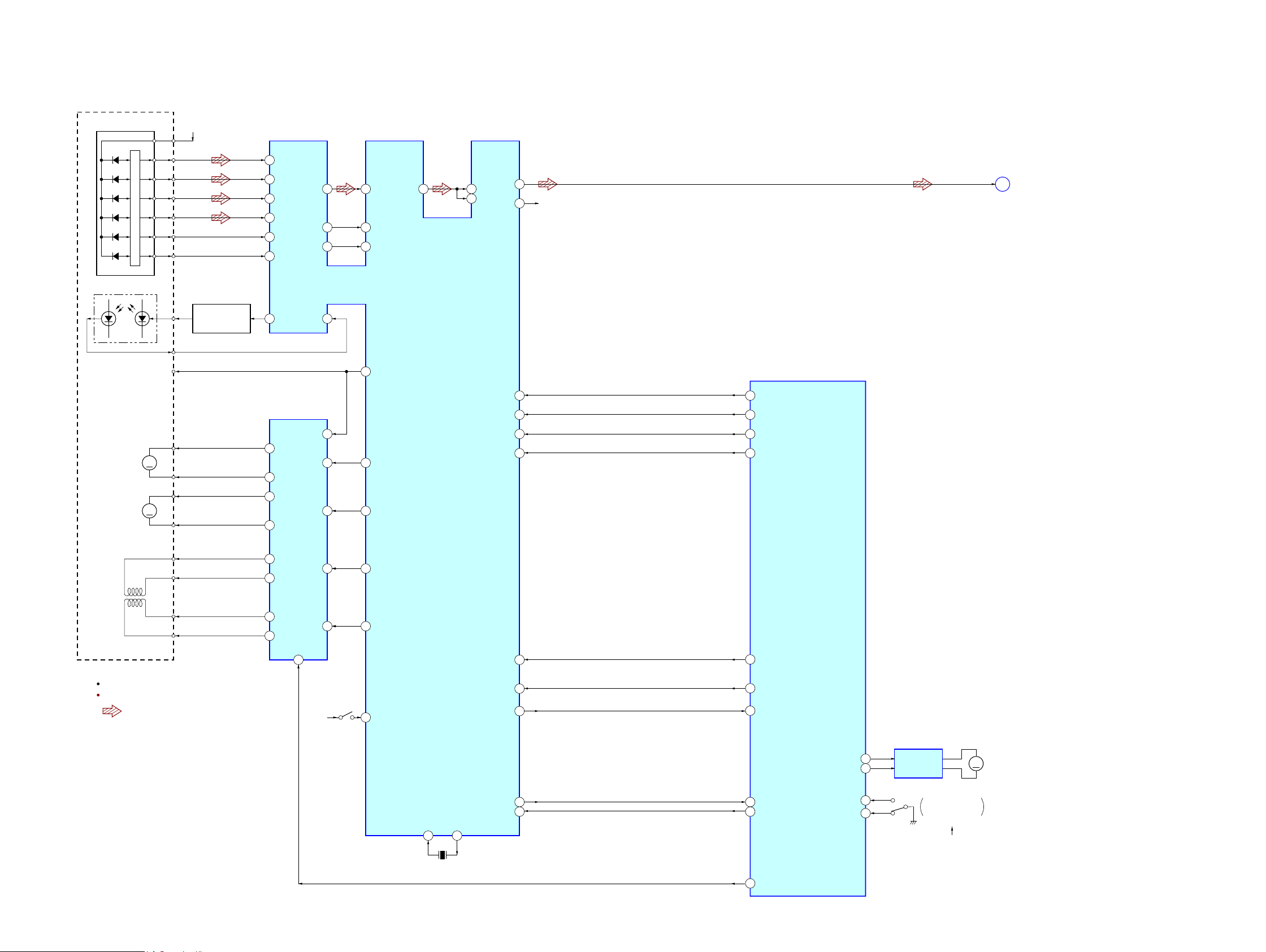
6-1. BLOCK DIAGRAM - CD SERVO Section -
SYSTEM CONTROLLER
IC301 (1/4)
CD-MP3 PROCESSOR
IC101
MUTE
2-AXIS
DEVICE
(TRACKING)(FOCUS)
95
89
A
AVD D
+3.3V
DETECTOR
FNi1 (A)
RFo
97 FPi1 (B)
88
2
AGCi
3RFRP RFZI
76TEi TEZi
83RFEQo 81 RFi
82 RFRPi
30LO
27RO
38BUS0
R-CH
94 FNi2 (C)
96 FPi2 (D)
100 TNi (E)
98 TPi (F)
91 LDo 92MDi
2VO1+
1VO1–
13 DMo
AUTOMATIC
POWER CONTROL
Q301
LD
PD
LASER DIODE
OPTICAL PICK-UP
BLOCK
(KSM-213DCP)
B
C
D
E
F
12 FMo
10 TRO
9FMO
20 IO0 (/HSO)
I-V AMP
M401
(SPINDLE)
M402
(SLED)
12 VO2–
11 V O2+
18 VO3+
17 VO3–
26 VO4+
27
7
IN4’
24
IN3’
20
IN2’
9
IN1
3
BIAS 23
84 VRo
VO4–
M
M
FOCUS/TRACKING COIL DRIVE,
SLED/SPINDLE MOTOR DRIVE
IC401
S201
(LIMIT)
DVDD
+3.3V
24
XO
23
XI
X102
16.9344MHz
60 CD DRIVER MUTE
LOADING
MOTOR DRIVE
IC311
CDM LOAD IN
85
CDM LOAD OUT
CDM SW (OPEN)
CDM SW (CLOSE)
84
88
87
M
A
CD-L
: CD PLAY
SIGNAL PATH
R-ch is omitted due to same as L-ch.
VCC
A
B
C
D
E
F
LD
PD
SP+
VC
SP–
SL+
SL–
T+
T–
F+
F–
3 CD BUS0
39BUS1 2 CD BUS1
40BUS2 (SO) 1 CD BUS2
70 CD CLK
41BUS3 (SI)
100
CD BUS3
42BUCK (CLK)
69 CD CCE
43XCCE
54SBSY
48PIO0
68 MP3 IREQ
19 SBSY
37XRST
59 CD RESET
S001
DISC TRAY
OPEN/CLOSE DETECT
OPEN
CLOSE
M001
(LOADING)
(Page 23)
 Loading...