

Sony HCD-BC150, HCD-BC250 Service Manual

HCD-BC150/BC250
SERVICE MANUAL
Ver 1.4 2004.09
SUPPLEMENT-4
Subject: CDM81 DISASSEMBLY
US Model
Canadian Model
E Model
HCD-BC150/BC250
Australian Model
HCD-BC150
9-877-956-84
HCD-BC150/BC250
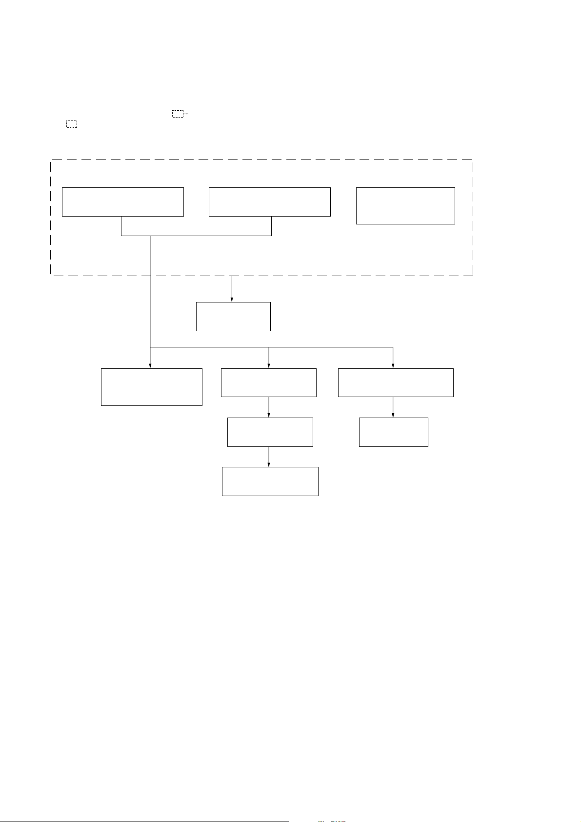
1-1. DISASSEMBLY FLOW
•This set can be disassembled in the order shown below.
•The dotted square with arrow (
) are completed.
(
) prompts you to move to the next job when all of the works within the dotted square
SECTION 1
CDM81 DISASSEMBLY
FORMER TYPE MODELS
(CDM81A-DVBU27)
2-14.BASE UNIT (DVBU27)
(See page 14 of Supplement-3)
1-2.GEAR (SUB TRAY 1),
GEAR (SUB TRAY 2)
(Page 3)
NEW TYPE MODELS
(CDM81C-DVBU100)
2-14.BASE UNIT (DVBU100)
(See page 14 of Supplement-2)
1-3.LEVER ASSY
(Page 3)
1-4.STOCKER SECTION
(Page 4)
1-5.CAM (STOCKER)
(Page 4)
*
2-13. MOTOR BOARD,
M761 (LD/ST MOTOR),
M762 (BU U/D MOTOR)
*
FORMER TYPE MODELS
(See page 13 of Supplement-3)
*
NEW TYPE MODELS
(See page 13 of Supplement-2)
1-7.ROTARY ENCODER (MD)
(Page 5)
1-8.GEAR (BU1)
(Page 6)
1-6.GEAR (STOCKER 3)
(Page 5)
2
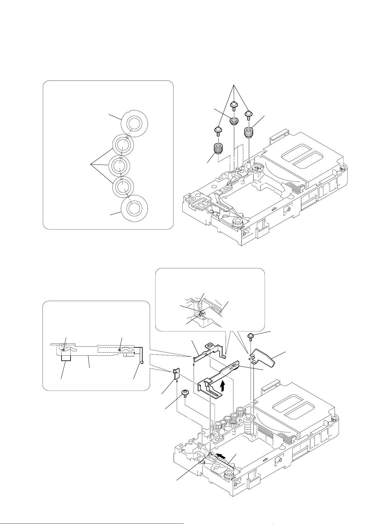
1-2. GEAR (SUB TRAY 1), GEAR (SUB TRAY 2)
HCD-BC150/BC250
PRECAUTION DURING GEAR (SUB TRAY 1/2) INSTALLATION
Align the marks of the gears as shown in the illustration.
4
(sub tray 1)
gear (sub tray 2)
gear (sub tray 1)
gear (sub tray 2)
3
1
(+PTPWH 2.6 × 8)
three gears
gear (sub tray 2)
three screws
2
gear (sub tray 2)
1-3. LEVER ASSY
Before re-assembling, align the lever (release)
and the lever (sub tray) with the lever (mode)
as shown in the illustration.
dowel dowel
lever (mode)
lever (release)
lever (sub tray)
6
lever (release)
3
(+PTPWH M2.6)
When re-assembling, insert the lever (sub tray)
between the bosses of the shutter (tray).
shutter (tray)
lever (sub tray)
boss
boss
5
lever (sub tray)
4
floating screw
1
screw
(+PTPWH 2.6 × 8)
2
shutter (tray)
7
lever (mode)
Before re-assembling, slide the cam (BU)
in the direction of the arrow.
cam (BU)
3
 Loading...