

Sony HBD-E780W, HBD-E985W, HBD-E980W Service Manual
BDV-E780W/E980W/E985W
MANUAL DE SERVIÇO
Ver. 1.2 2011.05
• BDV-E780W/E980W/E985W are composed of following models.
As service manuals are issued for each component model,
please refer to them.
120('202'(/2'2&20321(17(
BDV-E780W BDV-E980W BDV-E985W
BLU-RAY DISC/DVD receiver HBD-E780W HBD-E980W HBD-E985W
Front speaker SS-TSB107 SS-TSB108 SS-TSB108
Center speaker SS-CTB103 SS-CTB103 SS-CTB103
Surround speaker SS-TSB106 SS-TSB109 SS-TSB109
Subwoofer SS-WSB105 SS-WSB105 SS-WSB105
Surround amplifi er TA-SA300WR TA-SA300WR TA-SA300WR
Wireless transceiver EZW-RT50 EZW-RT50 EZW-RT50
Dock for iPod/iPhone TDM-iP30 TDM-iP30 TDM-iP30
Note 1: As for EZW-RT50 and TDM-iP30, the part number has been described to this service manual.
Note 2: TDM-iP30 for BDV-E985W is attached only to Singapore and Thai models.
SPECIFICATIONS
General
Power requirements
US, Canadian models:
Taiwan model:
Other models:
Power consumption On: 125 W (BDV-E985W)
Dimensions (approx.) 430 mm × 75 mm × 320
Mass (approx.) 4.1 kg (9 lb 1 oz)
Wireless transceiver (EZW-RT50)
Communication system Wireless sound
Frequency band
US, Canadian models:
Other models:
Modulation method DSSS
Power requirements DC 3.3 V, 300 mA
Dimensions (approx.) 30 mm × 9 mm × 60 mm
Mass (approx.) 10 g (
Design and specifications are subject to change
without notice.
US, Canadian models:
s Sta ndby power consumption 0 .3W (main unit),
0.13W (surround amplifier).
s Over 85% power efficiency of amplifier block is
achieved with the full digital amplifier, S-M
Other models:
s St andby power consumption 0.3W (main unit),
0.18W (surround amplifier).
s Ove r 85% power efficiency of amplifier block is
achieved with the full digital a mplifier, S-Master.
120 V AC, 60 Hz
120 V AC, 50/60 Hz
220 V - 240 V AC,
50/60 Hz
On: 130 W
(BDV-E780W/E980W)
Standby: 0.3 W (at the
Power Saving mode)
mm (17 in × 3 in ×
5
12
/8 in) (w/h/d) incl.
projecting parts
430 mm × 75 mm × 333
mm (17 in × 3 in ×
1
13
/8 in) (w/h/d) (with the
wireless transceiver
inserted)
Specification version 1.0
5.736 GHz - 5.814 GHz
5.725 GHz - 5.875 GHz
3
(1
/16 in × 3/8 in × 2 3/8 in)
(w/h/d)
1
/2 oz)
aster.
Unpacking
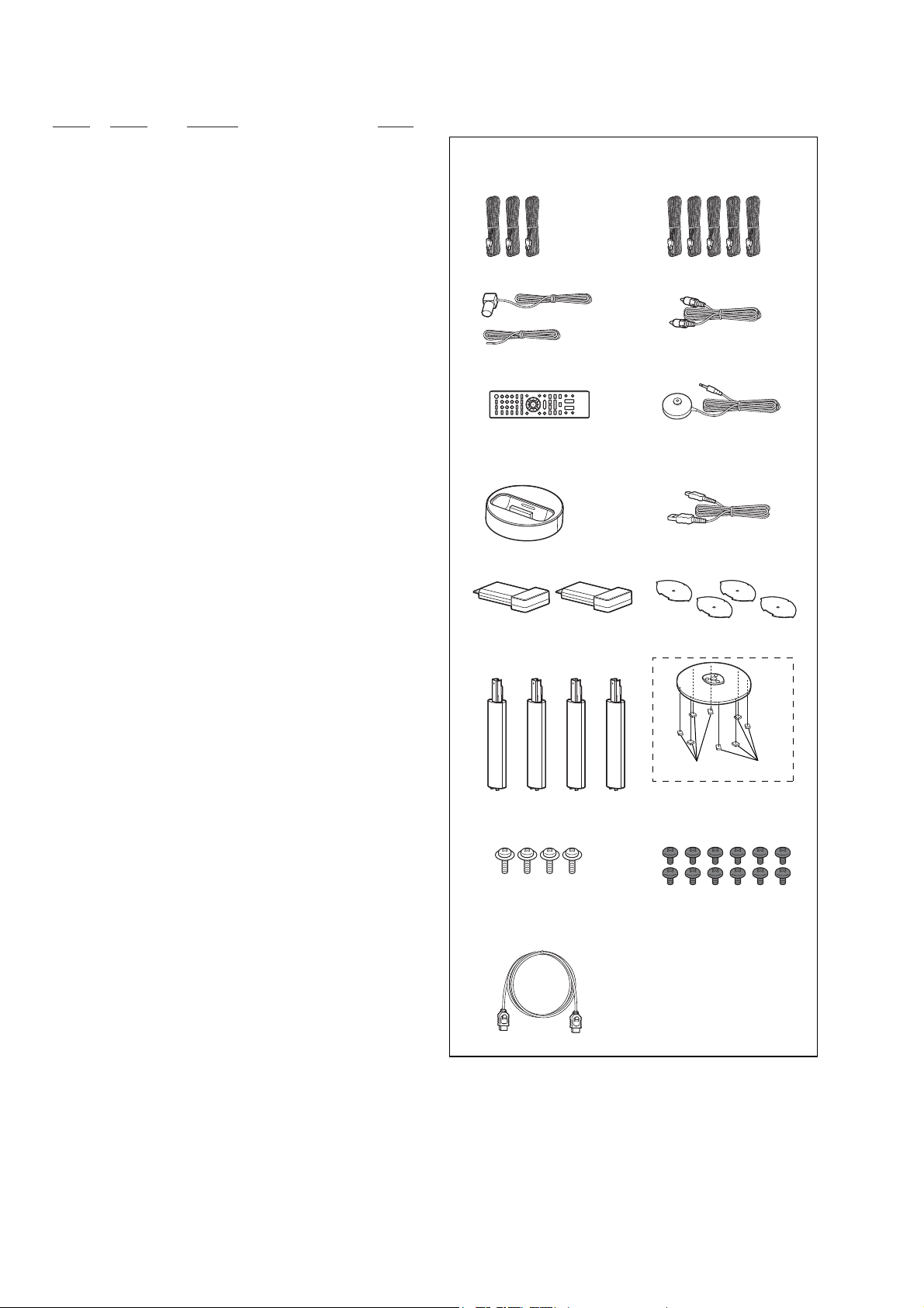
• Front speakers (2)
• Surround speakers (2)
• Center speaker (1)
• Subwoofer (1)
• Speaker cords (3, green/gray/blue) (BDV-E780W)
• Speaker cords (5, red/white/green/gray/blue) (BDV-E980W/E985W)
• Speaker-bottom covers (4) (BDV-E980W/E985W only)
• Bases (4) (BDV-E980W/E985W only)
• Lower parts of the front speakers (4) (BDV-E980W/E985W only)
• Screws (silver) (4) (BDV-E980W/E985W only)
• Screws (black) (12) (BDV-E980W/E985W only)
• FM wire antenna (aerial) (1)
• Video cord (1)
• Remote commander (remote) (1)
• R6 (size AA) batteries (2)
• Calibration mic (1)
• High Speed HDMI cable (1) (BDV-E985W only)
• Dock for iPod/iPhone (TDM-iP30) (1) (Except Saudi Arabian and Taiwan models)
• USB cable (1) (Except Saudi Arabian and Taiwan models)
• Surround amplif er (1)
• Wireless transceivers (4)
• Operating Instructions
• Quick Setup Guide
• Speaker Installation Guide
• Software Licence Information
• Easy Setup Disc (DVD) (US, Canadian models only)
• Wireless Product Compliance Information (AEP, Italian, UK models only)
BLU-RAY DISC/DVD HOME THEATRE SYSTEM
s iPho ne, iPod, iPod classic, iPod
US Model
UK Model
Canadian Model
Australian Model
AEP Model
BDV-E780W/E980W
Saudi Arabia Model
Singapore Model
Taiwan Model
Thai Model
nano, and iPod touch are
trademarks of Apple Inc.,
registered in the U.S. and other
countries.
– Refer to next page for accessories list –
BDV-E780W
BDV-E980W
BDV-E985W
9-893-131-03
2011E05-1
2011.05
©
Sony Corporation
Published by Sony Techno Create Corporation
BDV-E780W/E980W/E985W
Ver. 1.2
ACCESSORIES
Ref. No. Part No. Description Remark
4-261-379-11 MANUAL, INSTRUCTION (ENGLISH) (US, CND)
4-261-379-21 MANUAL, INSTRUCTION (FRENCH) (CND)
4-261-384-11 MANUAL, INSTRUCTION (ENGLISH) (EA, SP)
4-261-384-21 MANUAL, INSTRUCTION
(TRADITIONAL CHINESE) (SP, TW)
4-261-384-61 MANUAL, INSTRUCTION (ARABIC) (EA)
4-261-384-71 MANUAL, INSTRUCTION (THAI) (TH)
4-261-385-11 MANUAL, INSTRUCTION (ENGLISH) (UK, AUS)
4-261-385-21 MANUAL, INSTRUCTION
(FRENCH, SPANISH, GERMAN) (AEP, IT)
4-261-385-31 MANUAL, INSTRUCTION
(DUTCH, ITALIAN, POLISH) (AEP)
4-261-386-11 MANUAL, INSTRUCTION (PORTUGUESE)
(AEP, IT)
4-261-386-21 MANUAL, INSTRUCTION (SWEDISH) (AEP, IT)
4-261-386-31 MANUAL, INSTRUCTION (DANISH, FINNISH)
(AEP, IT)
4-261-386-41 MANUAL, INSTRUCTION (GREEK) (AEP, IT)
4-261-386-51 MANUAL, INSTRUCTION (CZECH, HUNGARIAN)
(AEP, IT)
4-261-386-61 MANUAL, INSTRUCTION (TURKISH) (AEP, IT)
1 Speaker cords (3, green/
gray/blue)
(BDV-E780W)
1 Speaker cords (5, red/white/
green/gray/blue)
(BDV-E980W/E985W)
2 FM wire antenna (aerial) (1) 3 Video cord (1)
or
4 Remote commander
(remote) (1)
6 Dock for iPod/iPhone
(TDM-iP30) (1)
(Except Saudi Arabian
and Taiwan models)
5 Calibration mic (1)
7 USB cable (1)
(Except Saudi Arabian
and Taiwan models)
4-261-386-71 MANUAL, INSTRUCTION (SLOVAKIAN) (AEP, IT)
4-261-885-11 DISC, SETUP (2011) (Easy Setup Disc (DVD))
(US, CND)
4-288-638-11 MANUAL, INSTRUCTION
(DUTCH, ITALIAN, POLISH) (IT)
1 1-842-743-21 CORD WITH CONNECTOR (SPEAKER)
(Speaker cords (3, green/gray/blue)) (E780W)
1 1-842-746-21 CORD WITH CONNECTOR (SPEAKER)
(Speaker cords (5, red/white/green/gray/blue))
(E980W/E985W)
2 1-754-060-21 ANTENNA (FM) (FM wire antenna (aerial))
(EXCEPT US, CND)
2 1-793-184-41 CONNECTOR (F TYPE ADAPTOR)
(FM wire antenna (aerial)) (US, CND)
3 1-838-669-11 CORD, CONNECTION (Video cord)
4 1-489-439-11 REMOTE COMMANDER (RM-ADP060)
(AEP, IT, UK, AUS)
4 1-489-440-11 REMOTE COMMANDER (RM-ADP059) (US, CND)
4 1-489-441-11 REMOTE COMMANDER (RM-ADP058) (E985W)
5 1-542-830-11 MEASUREMENT MIC (MONO)
(Calibration mic: ECM-AC2)
6 A-1797-336-A OVERALL ASSY (Dock for iPod/iPhone: TDM-iP30)
(EXCEPT EA, TW)
7 1-835-329-21 CORD, CONNECTION (USB5P) (USB cable)
(EXCEPT EA, TW)
8 1-489-359-11 RF MODULATOR (EZW-RT50)
(Wireless transceiver) (1 piece) (AEP, IT, UK)
8 1-489-360-11 RF MODULATOR (EZW-RT50)
(Wireless transceiver) (1 piece) (US, CND)
8 1-489-361-11 RF MODULATOR (EZW-RT50)
(Wireless transceiver) (1 piece) (AUS, EA, SP, TH)
8 1-489-368-11 RF MODULATOR (EZW-RT50)
(Wireless transceiver) (1 piece) (TW)
8 Wireless transceivers (2) 9 Speaker-bottom covers (4)
10 Lower parts of the front and
surround speakers (4)
(BDV-E980W/E985W only)
13 Screws (silver) (4)
(BDV-E980W/E985W only)
15 High Speed HDMI cable (1)
(Saudi Arabian, Singapore,
Thai and Taiwan models
only)
(BDV-E980W/E985W only)
11 Bases (4)
(BDV-E980W/E985W only)
12
14 Screws (black) (12)
(BDV-E980W/E985W only)
12
9 4-267-164-01 COVER (TB-EH) (Speaker-bottom cover) (1 piece)
10 A-1801-572-A STAND ASSY (TB)
11 A-1801-578-A STAND BASE ASSY (TB-EH) (Base) (1 piece)
12 4-162-924-11 FOOT (ST) (1 piece) (E980W/E985W)
13 7-682-973-31 SCREW +PSW 5X14 (Screw: silver) (1 piece)
14 7-682-574-09 SCREW +B 5X8 (Screw: black) (1 piece)
15 1-835-855-31 CORD WITH CONNECTOR (HDMI CABLE)
(Lower parts of the front speaker)
(High Speed HDMI cable) (E985W)
(E980W/E985W)
(1 piece) (E980W/E985W)
(E980W/E985W)
(E980W/E985W)
(E980W/E985W)
2
• Abbreviation
AUS : Australian model
CND : Canadian model
EA : Saudi Arabia model
IT : Italian model
SP : Singapore model
TH : Thai model
TW : Taiwan model

MEMO
BDV-E780W/E980W/E985W
3

BDV-E780W/E980W/E985W
REVISION HISTORY
Checking the version allows you to jump to the revised page.
Also, clicking the version at the top of the revised page allows you to jump to the next revised page.
Ver. Date Description of Revision
1.0 2011.03 New
1.1 2011.04 Addition of Italian model
1.2 2011.05 Addition of BDV-E985W
HBD-E780W/E980W/E985W
SERVICE MANUAL
Ver. 1.2 2011.05
Photo: HBD-E980W
• HBD-E780W is the Amplifi er, Video, HDMI, BD/DVD/Super Audio CD/CD System,
USB, LAN, Wireless LAN and FM Tuner section in BDV-E780W.
• HBD-E980W is the Amplifi er, Video, HDMI, BD/DVD/Super Audio CD/CD System,
USB, LAN, Wireless LAN and FM Tuner section in BDV-E980W.
• HBD-E985W pDVHomRGR AmplifiFDGRU, Video, HDMI, BD/DVD/Super Audio CD/CD System,
USB, LAN H 6LQWRQL]DGRUFM GR BDV-E985W.
Model Name Using Similar Mechanism BDP-S380
7LSRGH0HFDQLVPR
1RPHGD8QLGDGHÏWLFD Block Name
SPECIFICATIONS
Amplifier Section
U.S.models:
AUDIO POWER SPECIFICATIONS
POWER OUTPUT AND TOTAL HARMONIC
DISTORTION:
(FTC)
Front L + Front R: With 3 ohms loads , both
Other models:
POWER OUTPUT (rated)
Front L/F ront R: 108 W + 108 W (at 3 ohms,
POWER OUTPUT (reference)
Front L/Front R/Center: 167 W (per channel at
Subwoofer: 165 W (at 3 ohms, 80 Hz)
Inputs (Analog)
AUDIO (AUDIO IN) Sensitivity: 450/250 mV
Inputs (Digital)
SAT/CABLE (COAXIAL)
TV (Audio Return Channel/OPTICAL)
HDMI (IN 1)/HDMI (IN 2)
Video Section
Outputs VIDEO: 1 Vp-p 75 ohms
*For non-European/non-Saudi Arabia models only
channels driven, from 180
- 20,000 Hz; rated 60 watts
per channel minimum
RMS power, with no more
than 1% total harmonic
distortion from 250 milli
watts to rated output.
1 kHz, 1% THD)
3 ohms, 1
kHz)
Supported formats: LPCM
2CH (up to 48 kHz), Dolby
Digital, DTS
Supported formats: LPCM
2CH (up to 96 kHz), Dolby
Digital, DTS
COMPONENT*:
Y: 1 Vp-p 75 ohms
PB, PR: 0.7 Vp-p
75 ohms
HDMI Section
Connector Type A (19pin)
BD/DVD/Super Audio CD/CD System
Signal format system
U.S. and Canada models: NTSC
Other models: NTSC/PAL
USB Section
(USB) port: Type A (For connecting
LAN Section
LAN (100) terminal 100BASE-TX Terminal
Wireless LAN Section (HBD-E780W/E980W only)
Standards Compliance IEEE 802.11 b/g/n
Frequency and Channel 2.4 GHz - 2.4835 GHz
FM Tuner Section
System PLL quartz-locked digital
Tuning range
U.S. and Canada models: 87.5 MHz - 108.0 MHz
Other models: 87.5 MHz
Antenna (aerial) FM wire antenna (aerial)
Antenna (aerial) terminals 75 ohms, unbalanced
USB memory, me mory
card reader, digital still
camera, and digital video
camera)
[CH1 -11]
synthesizer
(100 kHz step)
- 108.0 MHz (50
kHz step)
BLU-RAY DISC/DVD RECEIVER
US Model
UK Model
HBD-E780W
Canadian Model
Australian Model
HBD-E980W
AEP Model
HBD-E780W/E980W
Saudi Arabia Model
Singapore Model
Taiwan Model
Thai Model
HBD-E985W
BPX-6
KEM-470AAA
General
Power requirements
US, Canadian models:
Taiwan model:
Other models:
Power consumption On: 1 30 W (HBD-E780W/E980W)
Dimensions (approx.) 430 mm × 75 mm × 320
Mass (approx.) 4.1 kg (9 lb 1 oz)
Design and specifications are subject to change
without notice.
s Standby power consumptio n 0.3W (main unit).
s Over 85% power efficiency of amplifier block is
achieved with the full digital amplifier, S-Master.
120 V AC, 60 Hz
120 V AC, 50/60 Hz
220 V - 240 V AC,
50/60 Hz
On: 125 W (HBD-E985W)
Standby: 0.3 W (at the
Power Saving mode)
mm (17 in × 3 in ×
5
12
/8 in) (w/h/d) incl.
projecting parts
430 mm × 75 mm × 333
mm (17 in × 3 in ×
1
13
/8 in) (w/h/d) (with the
wireless transceiver
inserted)
9-893-130-03
2011E05-1
2011.05
©
Sony Corporation
Published by Sony Techno Create Corporation
HBD-E780W/E980W/E985W
• This system incorporates with Dolby* Digital and Dolby Pro Logic (II) adaptive matrix surround
decoder and the DTS** Digital Surround System.
* Manufactured under license from Dolby Laboratories.
Dolby, Pro Logic, and the double-D symbol are trademarks of Dolby Laboratories.
** Manufactured under license under U.S. Patent #’s:
5,451,942; 5,956,674; 5,974,380; 5,978,762; 6,226,616; 6,487,535; 7,212,872; 7,333,929;
7,392,195; 7,272,567 & other U.S. and worldwide patents issued & pending.
DTS, DTS-HD and the Symbol are registered trademarks, & DTS-HD Master Audio, and
the DTS logos are trademarks of DTS, Inc. Product includes software. © DTS, Inc. All
Rights Reserved.
• This system incorporates High-Def nition Multimedia Interface (HDMI
the HDMI logo and High-Def nition Multimedia Interface are trademarks or registered trademarks of HDMI Licensing LLC in the United States and other countries.
• Java is a trademark of Oracle and/or its aff liates.
• “BD-LIVE” and “BONUSVIEW” are trademarks of Blu-ray Disc Association.
• “Blu-ray Disc” is a trademark.
• “Blu-ray Disc,” “DVD+RW,” “DVD-RW,” “DVD+R,” “DVDR,” “DVD VIDEO,” and “CD”
logos are trademarks.
• “Blu-ray 3D” and “Blu-ray 3D” logo are trademarks of Blu-ray Disc Association.
• “BRAVIA” is a trademark of Sony Corporation.
• “AVCHD” and the “AVCHD” logo are trademarks of Panasonic Corporation and Sony Corporation.
• , “XMB,” and “xross media bar” are trademarks of Sony Corporation and Sony Computer
Entertainment Inc.
• “PLAYSTATION” is a trademark of Sony Computer Entertainment Inc.
• Music and video recognition technology and related data are provided by Gracenote ®.
Gracenote is the industry standard in music recognition technology and related content delivery.
For more information, please visit www.gracenote.com. CD, DVD, Blu-ray Disc, and music and
video-related data from Gracenote, Inc., copyright © 2000-present Gracenote. Gracenote Software, copyright © 2000-present Gracenote. One or more patents owned by Gracenote apply to
this product and service. See the Gracenote website for a nonexhaustive list of applicable Gracenote patents. Gracenote, CDDB, MusicID, MediaVOCS, the Gracenote logo and logotype, and
the “Powered by Gracenote” logo are either registered trademarks or trademarks of Gracenote in
the United States and/or other countries.
TM
) technology. HDMI,
This appliance is classified as a
CLASS 1 LASER product. This
marking is located on the rear
exterior.
This appliance is classified as a
CLASS 3R LASER product.
Visible and invisible laser radiation
is emitted when the laser protective
housing is opened, so be sure to
avoid direct eye exposure.
This marking is located on the laser
protective housing inside the
enclosure.
SAFETY CHECK-OUT
After correcting the original service problem, perform the following safety check before releasing the set to the customer:
Check the antenna terminals, metal trim, “metallized” knobs,
screws, and all other exposed metal parts for AC leakage.
Check leakage as described below.
• The Wi-Fi CERTIFIEDTM. Logo is a certif cation mark of the Wi-Fi Alliance.
• The Wi-Fi Protected SetupTM. Mark is a mark of the Wi-Fi Alliance.
• “Wi-Fi CERTIFIEDTM.” and “Wi-Fi Protected SetupTM.” are trademarks of the Wi-Fi Alliance.
• “PhotoTV HD” and the “PhotoTV HD” logo are trademarks of Sony Corporation.
• MPEG Layer-3 audio coding technology and patents licensed from Fraunhofer IIS and Thomson.
• iPhone, iPod, iPod classic, iPod nano, and iPod touch are trademarks of Apple Inc., registered in
the U.S. and other countries.
• “Made for iPod,” and “Made for iPhone” mean that an electronic accessory has been designed
to connect specif cally to iPod or iPhone, respectively, and has been certif ed by the developer
to meet Apple performance standards. Apple is not responsible for the operation of this device
or its compliance with safety and regulatory standards. Please note that the use of this accessory
with iPod or iPhone may affect wireless performance.
• Windows Media is either a registered trademark or trademark of Microsoft Corporation in the
United States and/or other countries. This product contains technology subject to certain intellectual property rights of Microsoft. Use or distribution of this technology outside of this
product is prohibited without the appropriate license (s) from Microsoft. Content owners use
Microsoft PlayReady. content access technology to protect their intellectual property, including copyrighted content. This device uses PlayReady technology to access PlayReady-protected
content and/or WMDRMprotected content. If the device fails to properly enforce restrictions
on content usage, content owners may require Microsoft to revoke the device’s ability to consume PlayReadyprotected content. Revocation should not affect unprotected content or content
protected by other content access technologies. Content owners may require you to upgrade
PlayReady to access their content. If you decline an upgrade, you will not be able to access
content that requires the upgrade.
• DLNAR ®, the DLNA Logo and DLNA CERTIFIEDTM. are trademarks, service marks, or certif cation marks of the Digital Living Network Alliance.
• All other trademarks are trademarks of their respective owners.
• Other system and product names are generally trademarks or registered trademarks of the manufacturers. TM and ® marks are not indicated in this document.
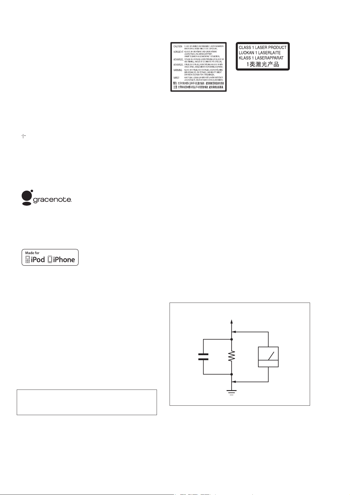
LEAKAGE TEST
The AC leakage from any exposed metal part to earth ground and
from all exposed metal parts to any exposed metal part having a
return to chassis, must not exceed 0.5 mA (500 microamperes.).
Leakage current can be measured by any one of three methods.
1. A commercial leakage tester, such as the Simpson 229 or RCA
WT-540A. Follow the manufacturers’ instructions to use these
instruments.
2. A battery-operated AC milliammeter. The Data Precision 245
digital multimeter is suitable for this job.
3. Measuring the voltage drop across a resistor by means of a
VOM or battery-operated AC voltmeter . The “limit” indication
is 0.75 V, so analog meters must have an accurate low-voltage
scale. The Simpson 250 and Sanwa SH-63Trd are examples
of a passive VOM that is suitable. Nearly all battery operated
digital multimeters that have a 2 V AC range are suitable. (See
Fig. A)
To Exposed Metal
Parts on Set
AC
1.5 kΩ0.15 μF
voltmeter
(0.75 V)
CAUTION
Use of controls or adjustments or performance of procedures
other than those specifi ed herein may result in hazardous radia-
tion exposure.
SAFETY-RELATED COMPONENT WARNING!
COMPONENTS IDENTIFIED BY MARK 0 OR DOTTED LINE
WITH MARK 0 ON THE SCHEMATIC DIAGRAMS AND IN
THE PARTS LIST ARE CRITICAL TO SAFE OPERATION.
REPLACE THESE COMPONENTS WITH SONY PARTS
WHOSE PART NUMBERS APPEAR AS SHOWN IN THIS
MANUAL OR IN SUPPLEMENTS PUBLISHED BY SONY.
2
Earth Ground
Fig. A. Using an AC voltmeter to check AC leakage.
ATTENTION AU COMPOSANT AYANT RAPPORT
À LA SÉCURITÉ!
LES COMPOSANTS IDENTIFIÉS PAR UNE MARQUE 0 SUR
LES DIAGRAMMES SCHÉMATIQUES ET LA LISTE DES
PIÈCES SONT CRITIQUES POUR LA SÉCURITÉ DE FONCTIONNEMENT. NE REMPLACER CES COMPOSANTS QUE
PAR DES PIÈCES SONY DONT LES NUMÉROS SONT DONNÉS DANS CE MANUEL OU DANS LES SUPPLÉMENTS
PUBLIÉS PAR SONY.

Ë1',&(
HBD-E780W/E980W/E985W
Ver. 1.2
1. 127$6'(6(59,d2 ...................................... 4
2. D(60217$*(0
2-1. Fluxo de Desmontagem ................................................. 11
2-2. Left Panel (E1), Right Panel (E1) ................................... 11
2-3. Loading Panel Assy (E1) ................................................ 12
2-4. Top Panel Block .............................................................. 12
2-5. FL Board ......................................................................... 13
2-6. Front Panel Block ........................................................... 13
2-7. Wireless LAN Card (WLC1) (E780W/E980W) ............. 14
2-8. Top Lid Block ................................................................. 14
2-9. BD Drive (BPX-6) .......................................................... 15
2-10. WS Board ........................................................................ 15
2-11. AMP Board ..................................................................... 16
2-12. Switching Regulator (SWR1) ......................................... 17
2-13. MB-141 Board ................................................................ 18
2-14. Optical Pick-up Block (KEM-470AAA),
Wire (Flat Type) .............................................................. 19
2-15. Como dobrar o cabo flat FFC.......................................... 20
3. MODO DE TESTE ................................................... 21
4. VERIFICAÇÃO ELÉTRICA .................................. 30
5. DIAGRAMAS
5-1. Diagrama em Bloco - Seção SERVO - .......................... 31
5-2. Diagrama em Bloco - Seção MEMORY - ...................... 32
5-3. Diagrama em Bloco - Seção HDMI - ................ 33
5-4. Diagrama em Bloco - Seção MAIN -.............................. 34
5-5. Diagrama em Bloco - Seção AMP -............................... 35
5-6. Diagrama em Bloco - Seção POWER SUPPLY ........... 36
5-7. Placa de Circuito Impresso - Placa MB-141 (Lado A) - 38
5-8. Placa de Circuito Impresso - Placa MB-141 (Lado B) - 39
5-9. Diagrama Esquemático - Placa MB-141 (1/12) - ............ 40
5-10. Diagrama Esquemático - Placa MB-141 (2/12) - ........ 41
5-11. Diagrama Esquemático - Placa MB-141 (3/12) - ......... 42
5-12. Diagrama Esquemático - Placa MB-141 (4/12) - ......... 43
5-13. Diagrama Esquemático - Placa MB-141 (5/12) -........... 44
5-14. Diagrama Esquemático - Placa MB-141 (6/12) - ........... 45
5-15. Diagrama Esquemático - Placa MB-141 (7/12) -........... 46
5-16. 'LDJUDPD(VTXHPiWLFR- 3ODFDMB-141 (8/12) -........... 47
5-17. Diagrama Esquemático - Placa MB-141 (9/12) - .......... 48
5-18. Diagrama Esquemático - Placa MB-141 (10/12) -........ 49
5-19. Diagrama Esquemático - Placa MB-141 (11/12) - ....... 50
5-20. Diagrama Esquemático - Placa MB-141 (12/12) - ........ 51
5-21. PODFDGH&LUFXLWR,PSUHVVR
- AMP Board (/DGRComponentH) - ............................... 52
5-22. PODFDGH&LUFXLWR,PSUHVVR
- AMP Board (/DGR6ROGD) - .................................... 53
5-23. 'LDJUDPD(VTXHPiWLFR - 3ODFDAMP (1/2) -................. 54
5-24. Diagrama Esquemático - Placa AMP (2/2) - ................. 55
5-25. Placa de Circuito Impresso - Seção INPUT/OUTPUT - 56
5-26. Diagrama Esquemático - Seção INPUT/OUTPUT - ...... 57
5-27. Placa de Circuito Impresso - Placa WS - ........................ 58
5-28. Diagrama Esquemático - Placa WS - ............................ 59
5-29. Placa de Circuito Impresso - Placas FL, TOUCH -....... 60
5-30. Diagrama Esquemático - Placas FL, TOUCH -.............. 61
5-31. PODFDGH&LUFXLWR,PSUHVVR- 3ODFDTUNER -................ 62
5-32. 'LDJUDPD(VTXHPiWLFR - 3ODFDTUNER - ....................... 62
6. 9,67$(;3/2','$
6-1. Seção Panel ................................................................... 85
6-2. Seção Front Panel ......................................................... 86
6-3. Seção Back Panel ......................................................... 87
6-4. Seção Chassis... ............................................................... 88
6-5. Seção BD Drive (BPX-6) ................................................ 89
7. /,67$'(3(d$6(/e75,&$6........................ 90
NOTES ON CHIP COMPONENT REPLACEMENT
• Never reuse a disconnected chip component.
• Notice that the minus side of a tantalum capacitor may be damaged by heat.
FLEXIBLE CIRCUIT BOARD REPAIRING
• Keep the temperature of soldering iron around 270 °C during
repairing.
• Do not touch the soldering iron on the same conductor of the
circuit board (within 3 times).
• Be careful not to apply force on the conductor when soldering
or unsoldering.
3
HBD-E780W/E980W/E985W
SECTION 1
NOTAS DE SERVIÇO
NOTES ON HANDLING THE OPTICAL PICK-UP
BLOCK OR BASE UNIT
The laser diode in the optical pick-up block may suffer electrostatic break-down because of the potential difference generated by
the charged electrostatic load, etc. on clothing and the human body .
During repair, pay attention to electrostatic break-down and also
use the procedure in the printed matter which is included in the
repair parts.
The f exible board is easily damaged and should be handled with
care.
NOTES ON LASER DIODE EMISSION CHECK
The laser beam on this model is concentrated so as to be focused
on the disc ref ective surface by the objective lens in the optical
pickup block. Therefore, when checking the laser diode emission,
observe from more than 30 cm away from the objective lens.
UNLEADED SOLDER
Boards requiring use of unleaded solder are printed with the leadfree mark (LF) indicating the solder contains no lead.
(Caution: Some printed circuit boards may not come printed with
the lead free mark due to their particular size)
: LEAD FREE MARK
Unleaded solder has the following characteristics.
• Unleaded solder melts at a temperature about 40 °C higher
than ordinary solder.
Ordinary soldering irons can be used but the iron tip has to be
applied to the solder joint for a slightly longer time.
Soldering irons using a temperature regulator should be set to
about 350 °C.
Caution: The printed pattern (copper foil) may peel away if
the heated tip is applied for too long, so be careful!
• Strong viscosity
Unleaded solder is more viscous (sticky, less prone to f ow)
than ordinary solder so use caution not to let solder bridges
occur such as on IC pins, etc.
• Usable with ordinary solder
It is best to use only unleaded solder but unleaded solder may
also be added to ordinary solder.
NOTE OF REPLACING THE IC101, IC304, IC307,
IC501, IC702, IC5301 AND IC5307 ON THE MB-141
BOARD
IC101, IC304, IC307, IC501, IC702, IC5301 and IC5307 on the
MB-141 board cannot exchange with single. When these parts are
damaged, exchange the complete mounted board.
NOTE OF REPLACING THE IC106, IC107, IC206 AND
IC207 ON THE MB-141 BOARD
Replacement of IC106, IC107, IC206 and IC207 on the MB-141
board used in this unit requires a special tool.
TEST DISC
Part No. Description Layer
J-6090-199-A BLX-104 Single Layer
J-6090-200-A BLX-204 Dual Layer
J-2501-307-A CD (HLX-A1)
J-2501-305-A HLX-513 Single Layer (NTSC)
J-2501-306-A HLX-514 Dual Layer (NTSC)
J-6090-077-A HLX-506 Single Layer (PAL)
J-6090-078-A HLX-507 Dual Layer (PAL)
Note: Refer to the service manual of BDP-BX1/S350 (Part No. 9-883-
989-1[]) (page 1-3 to 1-14E) for the use of BLX-104/204.
Operation and Display:
1. BLX-104
Procedure:
1. Select 23.976Hz/1080p.
2. Play “4.Motion picture”.
3. Check whether player can play back or not.
4. Check each outputs.
Video:
Composite/S Video/component/HDMI.
Audio:
Speaker out.
* When 1080/24p monitor is nothing, 1080i (59.94Hz or 50Hz)
can use instead of 1080/24p.
However this is temporary correspondence.
RELEASING THE DISC TRAY LOCK
The disc tray lock function for the antitheft of an demonstration
disc in the store is equipped.
Releasing Procedure:
1. Press the [
2. Touch the [FUNCTION] sensor to select “BD/DVD”.
3. Touch the [x] and [Z] sensors simultaneously and hold down
unit “DEMO OFF” displayed on the fluorescent indicator tube
(around 5 seconds).
Note: When “DEMO LOCK” is displayed, the disc tray lock is not re-
leased by turning power on/off with the [
ABOUT THE LENS CLEANING
Do not do the lens cleaning with the cotton bud etc. It causes the
trouble.
] button to turn on the system.
?/1
?/1
] button.
4
2. BLX-204
Procedure:
1. Select 1080i (59.94Hz or 50Hz).
2. Play “4.Motion picture”.
3. Check whether player can play back or not (Check the picture
and sound output).
3. CD (HLX-A1)
Procedure:
Check whether player can play back or not (Check the sound output).
4. HLX-513/514 (NTSC), HLX-506/507 (PAL)
Procedure:
1. After displayed Main Menu, select “1.Video Signal”.
2. Play “1.Color bar 100%” (Check the picture and sound output).
3. Return to Menu.
4. Play “Demonstration 4:3” or “Demonstration 16:9” (Check the
picture and sound output).

HBD-E780W/E980W/E985W
NOTE OF REPLACING THE OPTICAL DEVICE (KEM470AAA) OR MB-141 BOARD
The password will be supplied to only service HQ, and
service center name, q’ty and all of software registered
information should be maintained by service HQ, and
Audio will ask to report the registration information.
Optical device (KEM-470AAA) for BD requires precise read out
functions and secure contents protection system for more than past
DVD/CD.
Therefore, in the case repaired as follows, the writing work of the
OP data is necessary.
• When the optical device (KEM-470AAA) is replaced (The
MB-141 board doesn’t replace).
• When both the optical device (KEM-470AAA) and MB-141
board are replaced.
• When the MB-141 board is replaced (The optical device
(KEM-470AAA) doesn’t replace) (In this case, do the work of
“3. Optical device (KEM-470AAA) replacement” other than
the replacement of new optical device).
Note: The servo adjustment is done while writing the OP data. The manual
adjustment is unnecessary.
LD ON TIME history doesn’t carry over.
Do not touch any optical block parts, turn table and during replac-
ing. BD laser diode is very sensitive.
1. Preparation
1-1. ESD Countermeasure
It is necessary to conf rm the state of static electricity in the work
space before the repair is started.
The static electricity resistance of the BD laser is weaker than that
of the DVD/CD laser.
Do work space and worker’s ESD countermeasures to prevent destruction by ESD.
1-2. Jig
• Digital camera (Recommend with macro mode)
• USB memory
• PC
• Barcode decoder (Refer to “1-3. Barcode decoder
(BDPRdec)”)
1-3. Barcode decoder (BDPRdec)
Part No. : J-6090-212-A
Jig name : BDPRdec.exe
Release : 2010.11.26
Version : 2.0.0.0
Software contents :
• BDPRdec.exe : Barcode decoder software
• SavePath.ini : Decoded f le destination setting f le (Ini-
tial destination is “C:\BuData.txt”)
• TasmanBars.dll : Decode dll
• Uninst.exe : Uninstall the “BDPRdec.exe” from PC
Install procedure:
1. Unzip the barcode decoder f les to any PC folder.
2. Check the attached 2D code photo (OK_sample.JPG) drag &
drop onto “BDBUDec.exe”.
When the barcode decoder is used for the f rst time, the pass-
word is necessary. It is unnecessary since the second times.
Note 1: The password will be supplied to only service headquarters, and
service center name/q’ty/all of software registered information
should be maintained by service headquarters.
Note 2: Do not change the decoded f le name “BuData.txt”.
3. When “.NET frame work requirements” is displayed, down-
load following applications from Microsoft download site.
• Microsoft .NET Framework Version 2.0 Redistributable Pack-
age (x86)
http://www.microsoft.com/downloads/details.aspx?displaylan
g=en&FamilyID=0856eacb-4362-4b0d-8edd-aab15c5e04f5
• Microsoft .NET Framework 2.0 Service Pack 1 (x86)
http://www.microsoft.com/downloads/details.aspx?displaylan
g=en&FamilyID=79bc3b77-e02c-4ad3-aacf-a7633f706ba5
How to use:
Case 1 Drag & drop 2D code photo onto “BDPRdec.exe”.
Case 2 Drag & drop BU data f le onto “BDPRdec.exe”.
Data f le name be changed to specify format and end of
7 character are def ned.
You can also enter the f le path at the prompt.
5
HBD-E780W/E980W/E985W
2. Pass-fail judgment of the optical device (KEM-470AAA)
Perform pass-fail judgment to judge whether the repair of the optical device (KEM-470AAA) is necessary.
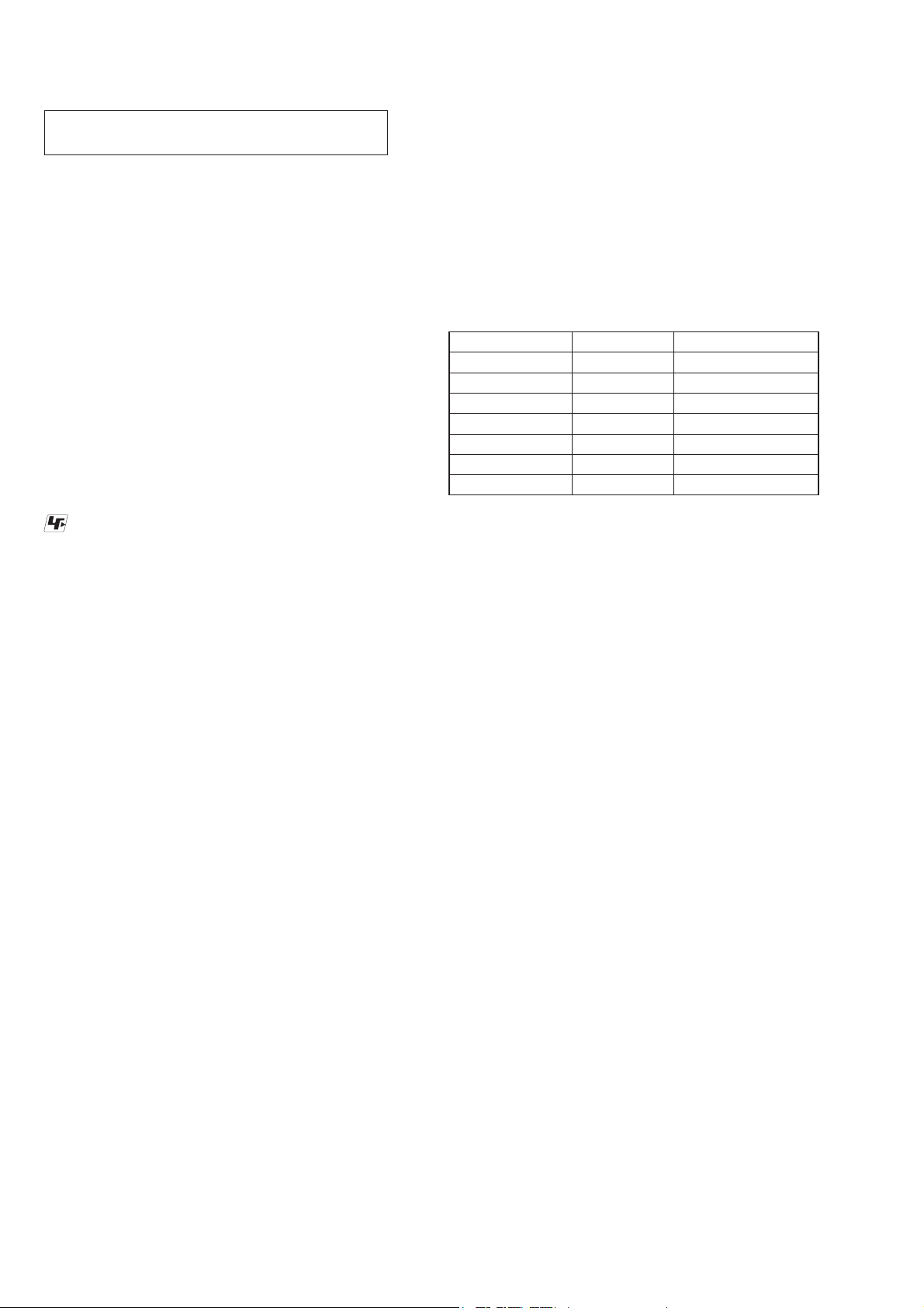
2-1. Flow of drive section check
Confirm whether
BD (BLX-104) can be
reproduced
YES
NO
Confirm whether the
drive voltage is the
CN5301 pin 3 : 12 V
CN309 pin 1 : 5 V
NO
following values
YES
Confirm F5301 to
F5303 and F5305
on the MB-141 board,
and replace it
when it has been
damaged
Confirm OP FFC cable
(Part No. 1-838-615-11)
and SPD FFC cable
(Part No. 1-838-617-11),
and replace it when it
has been damaged
Then, confirm whether
this unit operates
normally
YES
OK
Confirm whether
DVD (HLX-513)/
CD (HLX-A1) can be
reproduced
Note: Refer to “2-14. OPTICAL PICK-UP BLOCK (KEM-470AAA), WIRE (FLAT TYPE)” (page 19) about how to remove the FFC HOLDER (REAR).
NO
NO NO
Confirm whether the
optical device IOP
is normal in the
service mode
(Refer to “2-2. Flow
of optical device
IOP check”)
Repalece the
optical device
(KEM-470AAA)
(Refer to “3. Optical
device (KEM-470AAA)
replacement”)
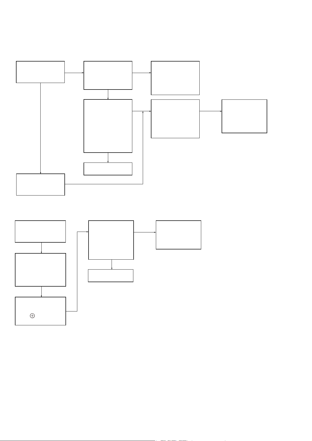
2-2. Flow of optical device IOP check
Turn the power on,
and change function
to “BD/DVD”
Press the buttons on
the remote commander
in order of [DISPLAY],
[0], [2], [1] [SUBTITLE],
and enter the service
mode
Confirm whether
value is the
specification value
Specification value:
BD : ±3 mA
DVD/CD: ±3 mA
YES
OK
NO
Repalece the
optical device
(Refer to “3. Optical
device (KEM-470AA)
replacement”)
Press the buttons on
the remote commander
in order of [8], [7], [3],
[ ], and the
dIOP value is displayed
6
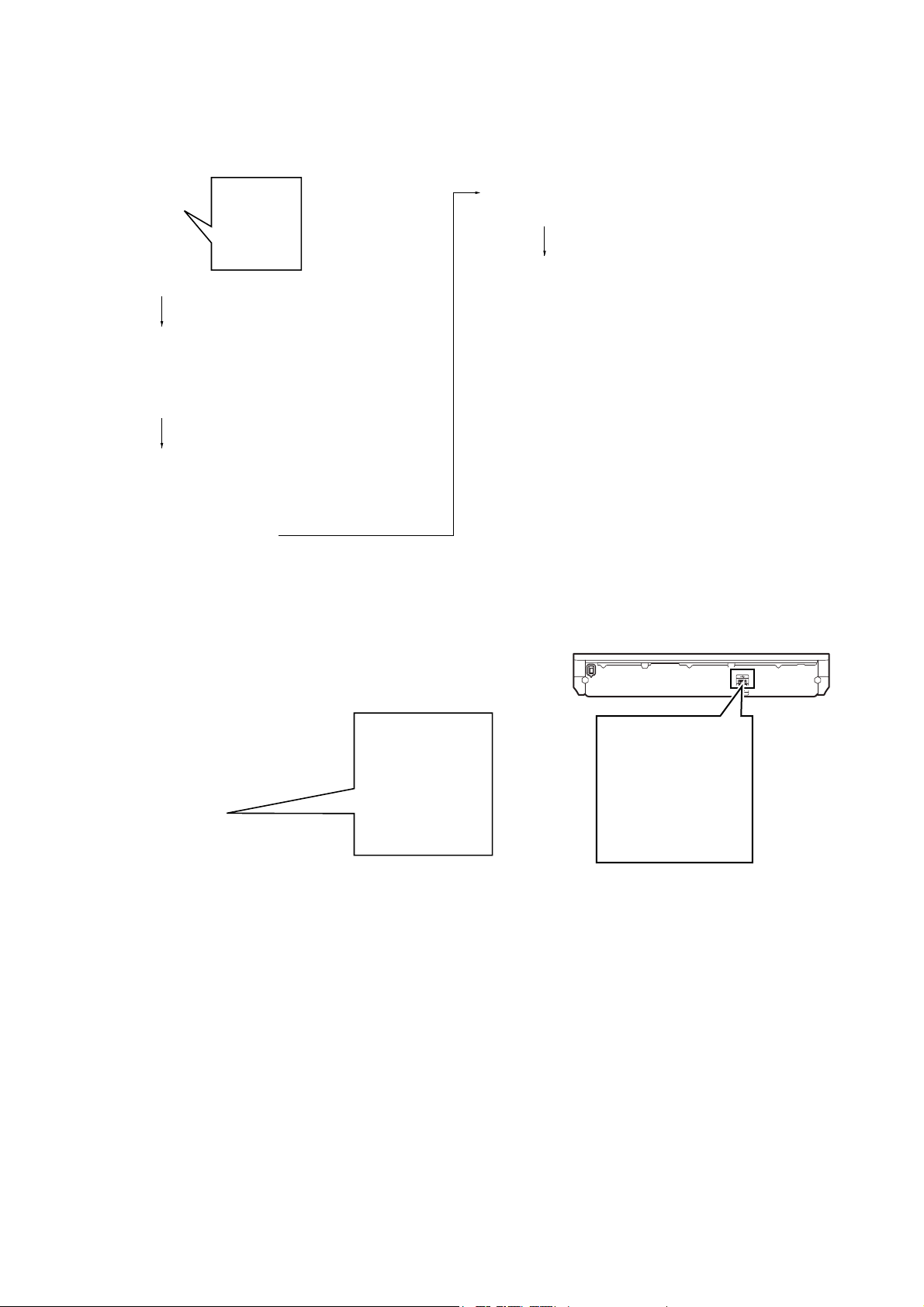
3. Optical device (KEM-460AAA) replacement
Flow of replacement:
Note: The photo in f ow is an image.
Barcode label on
new optical device
(KEM-470AAA)
bottom side
Take photo (JPEG)
by digital camera
Change photo into
the text data with
the barcode decoder
HBD-E780W/E980W/E985W
Save the text data
to USB memory
(memory capacity
need not be 8GB)
Connect USB memory
with rear USB connector
on this unit, and read the
text data by the service mode
Procedure:
1. Remove the INSULATOR (4 pieces) and broken optical device (KEM-470AAA) from LOADING ASSY.
2. Take photo of the barcode on new optical device (KEM470AAA) bottom side by digital camera.
3. Assemble the INSULATOR (4 pieces) to new optical device
(KEM-470AAA), f x (Torque value: 2 kgf) it to LOADING
ASSY with screw, and assemble this unit.
4. Drag & drop the taken photo by step 2 to “BDPRDec.exe”, and
make the text data (File name: BuData.txt).
5. Save the text data to USB memory.
6. Connect USB memory with rear USB connector on this unit,
and turn the power on.
– Rear view –
LAN (100)
Rear USB connector
7. Press the [FUNCTION] button on the remote commander to
select “BD/DVD”.
8. Press the buttons on the remote commander in order of
[DISPLAY], [0], [2], [1], [SUBTITLE], and enter the service
mode.
9. Press the buttons on the remote commander in order of [8], [1],
[ENTER], and execute “[1] Drive OP data Write”.
10. Turn the power off after writing the OP data.
11. Turn the power on, and enter the service mode again.
12. Press the buttons on the remote commander in order of [8], [7],
[3], [ENTER], and the dIOP value is displayed.
13. Conf rm value is the following specif cation value, and turn the
power off.
Specif cation value:
BD : ±3 mA
DVD/CD : ±3 mA
14. Turn the power on, conf rm playback performance of the BD
(BLX-104)/DVD (HLX-513)/CD (HLX-A1).
15. Completely assemble this unit, and complete the repair.
7
HBD-E780W/E980W/E985W
Ver. 1.2
NOTE THE BD DRIVE (BPX-6) PARTS REPLACING
The mechanism blocks except optical device of BD drive (BPX-6)
are chief y composed of the following parts.
• CHUCK HOLDER ASSY
• LOADING ASSY
• HOLDER, FFC (REAR)
These parts are produced by two venders, it is not compatible.
Therefore, CHUCK HOLDER ASSY and LOADING ASSY are
supplied by one pair as repair parts. Please exchange both CHUCK
HOLDER ASSY and LOADING ASSY at the same time.
HOLDER FFC (REAR) need not be exchanged at the same time.
Note 1: The laser caution label is not pasted to LOADING FOR SER-
VICE. Please peel off an original laser caution label, and paste
it to LOADING FOR SERVICE when you use LOADING FOR
SERVICE.
LASER CAUTION LABEL
LOADING FOR SERVICE
CHUCK HOLDER ASSY
MODEL IDENTIFICATION
- Rear view -
Part No.
Model Part No.
E780W: AEP, Italian and UK models
E980W: Australian/
E985W: Singapore, Taiwan and Thai models
E980W: AEP, Italian/
E985W: Saudi Arabia models
E780W: US model
E980W: Canadian model
4-256-820-3[]
4-256-820-7[]
4-256-820-8[]
4-257-163-1[]
4-257-163-3[]
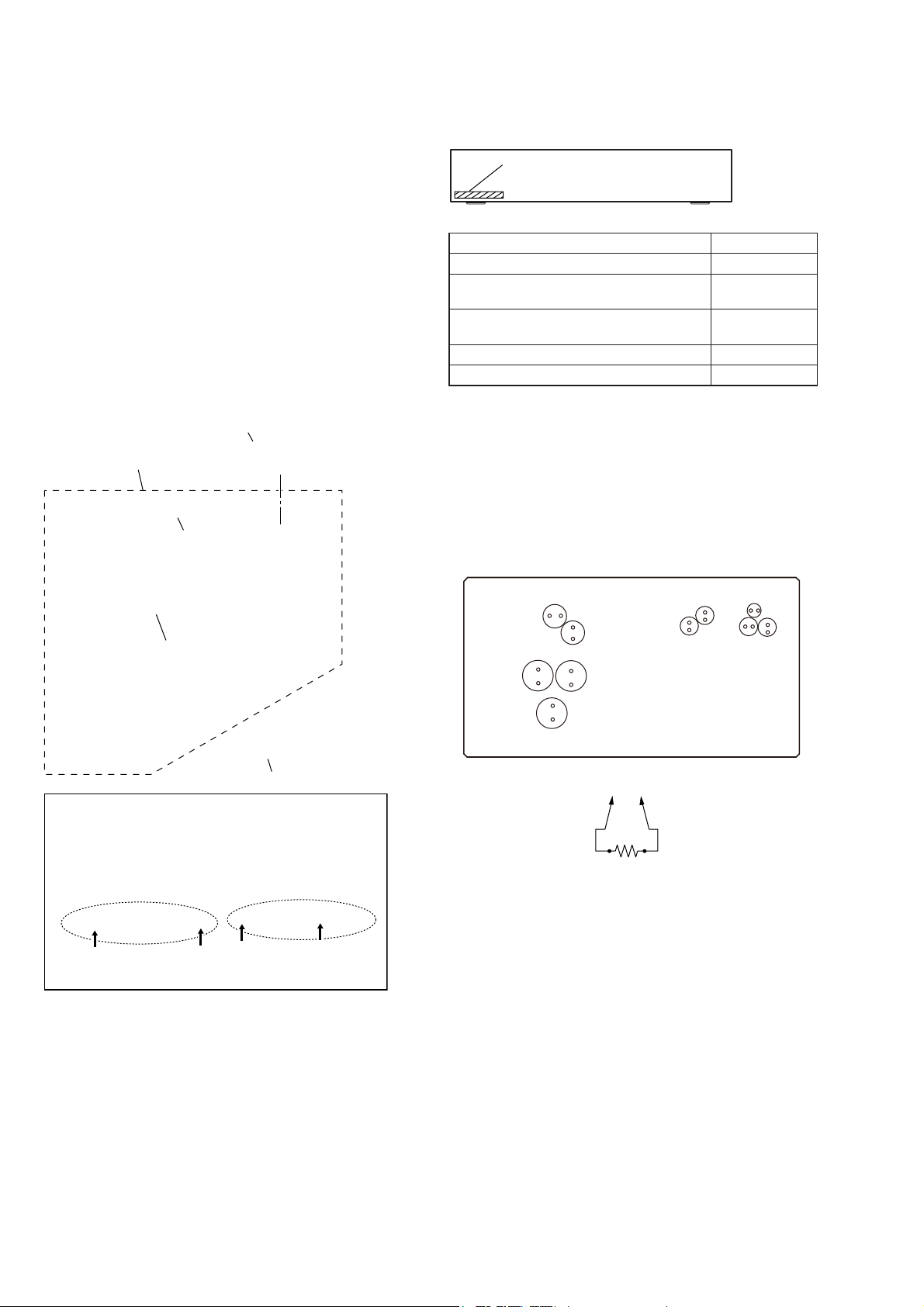
CAPACITOR ELECTRICAL DISCHARGE PROCESSING
When checking the board, the electrical discharge is necessary for
the electric shock prevention.
Connect the resistor to both ends of respective capacitors.
• Switching regulator
C1, C3, C4, C101, C102, C305, C306, C309, C310, C313
– SWICTHING REGULATOR (Conductor Side) –
LOADING ASSY
HOLDER, FFC (REAR)
/LPLWVDPSOHLQVWDWHRIODVHUFDXWLRQODEHO
If laser caution label is a condition of the figure below,
Note 2:
it is acceptable.
C102
C101
C3
C4
C1
(To both ends of each capacitor)
800 :/2 W
C313
C310
C306
C305
C309
8
HBD-E780W/E980W/E985W
Ver. 1.2
NOTE OF REPLACING THE IC3100 AND IC3200 ON
THE AMP BOARD AND THE COMPLETE AMP BOARD
When IC3100 and IC3200 on the AMP board and the complete
AMP board are replaced, it is necessary to spread the compound
(THERMAL COMPOUND (G747)) (Part No. J-2501-221-A ) between parts and heat sink.
Spread the compound referring to the f gure below.
– AMP Board (Component Side) –
IC3100
IC3200
CHECKING METHOD OF NETWORK OPERATION
It is necessary to check the network operation, when replacing the
MB-141 board. Check the operation of wireless and wired LAN,
according to the following method.
1. Checking Method of Wireless LAN Operation
(HBD-E780W/E980W only)
Check that access point is recognized surely.
Necessary Equipment:
Wireless access point with router function (AP)
Procedure:
1. Press the [HOME] button on the remote commander to enter
the home menu.
2. Press the [m]/[M]/[<]/[,] buttons on the remote commander to select “Network Settings”→“Internet Settings”, and press
the [ ] button on the remote commander.
3. Press the [m]/[M] buttons on the remote commander to select
“Wireless Setup (built-in)”, and press the [ ] button on the
remote commander.
4. Press the [m]/[M] buttons on the remote commander to select
“Scan”, and press the [ ] button on the remote commander.
5. The system starts searching for access points, and displays a
list of up available network name (SSID).
6. Check that access point (SSID) is displayed on the searching
result.
Note: Refer to the instruction manual about details of the setting method.
IC3100 IC3200
2. Checking method of wired LAN operation
Check that access point is recognized surely.
Procedure:
1. Connect the main unit to the router or the hub, etc. with the
LAN cable.
2. Press the [HOME] button on the remote commander to enter
the home menu.
3. Press the [m]/[M]/[<]/[,] buttons on the remote commander to select “Network Settings”→“Internet Settings”, and press
the [ ] button on the remote commander.
4. Press the [m]/[M] buttons on the remote commander to select
“Wired Setup”, and press the [ ] button on the remote commander.
5. Press the [m]/[M]/[<]/[,] buttons on the remote commander to select “Auto”, and press the [ ] button on the remote
commander.
6. Press the [,] button on the remote commander.
7. Press the [m]/[M] buttons on the remote commander to select
“Save & Connect”, and press the [ ] button on the remote
commander.
8. When “Internet Settings is now complete.” appears, then press
the [ ] button on the remote commander.
9. Press the [HOME] button on the remote commander to enter
the home menu.
10. Press the [m]/[M]/[<]/[,] buttons on the remote commander to select “Network Settings”→“Internet Settings”, and press
the [ ] button on the remote commander.
11. Press the [m]/[M] buttons on the remote commander to select
“Network Connection Diagnostics”, and press the [ ] button
on the remote commander.
12. Press the [<]/[,] buttons on the remote commander to
select “Start”, and press the [ ] button on the remote commander.
13. Check that IP address can be acquired.
Note: Refer to the instruction manual about details of the setting method.
9
HBD-E780W/E980W/E985W
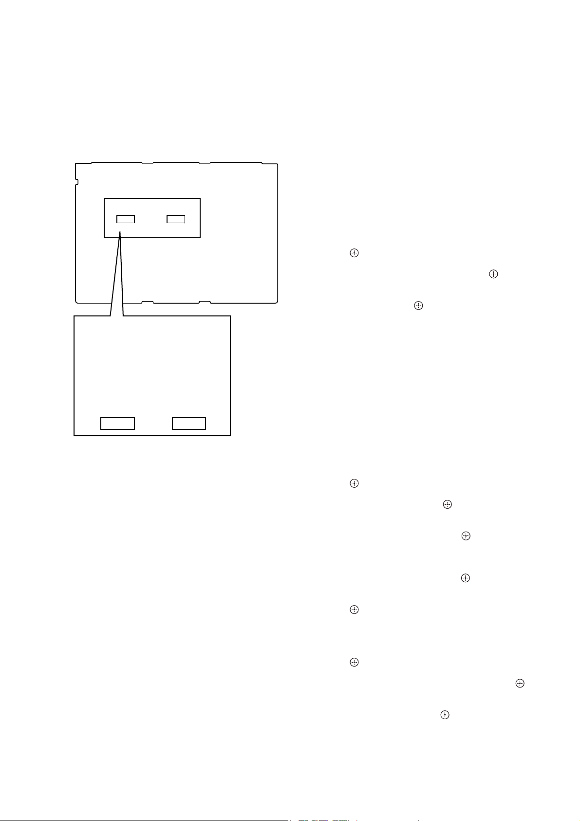
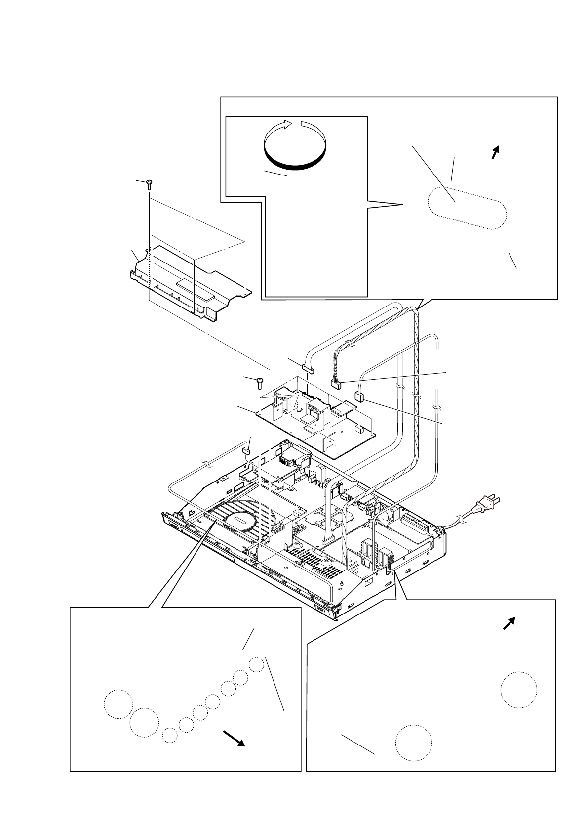
HOW TO OPEN THE TRAY WHEN POWER SWITCH TURN OFF
Note 1: After the left panel (E1) is removed, this work is done.
Note 2: Please prepare the thin wire (clip etc. processed to the length of 8 cm or more).
1 Remove the left panel (E1).
(Illustration of disassembly is omitted.)
hole
– Side view –
Insert the clip etc.
processed to the
length of 8 cm or
more in the hole
on the side of the
chassis and push.
8 cm or more
Push after it inserts it in this hole well.
Note:
SERVICE POSITION
POWER_SIRCS board
FL board
BD drive
tray
– Top view –
tray
3
2 Insert the clip etc.
10
MB-141 board
BD drive
(BPX-6)
AMP board
switching regulator
(SWR1)
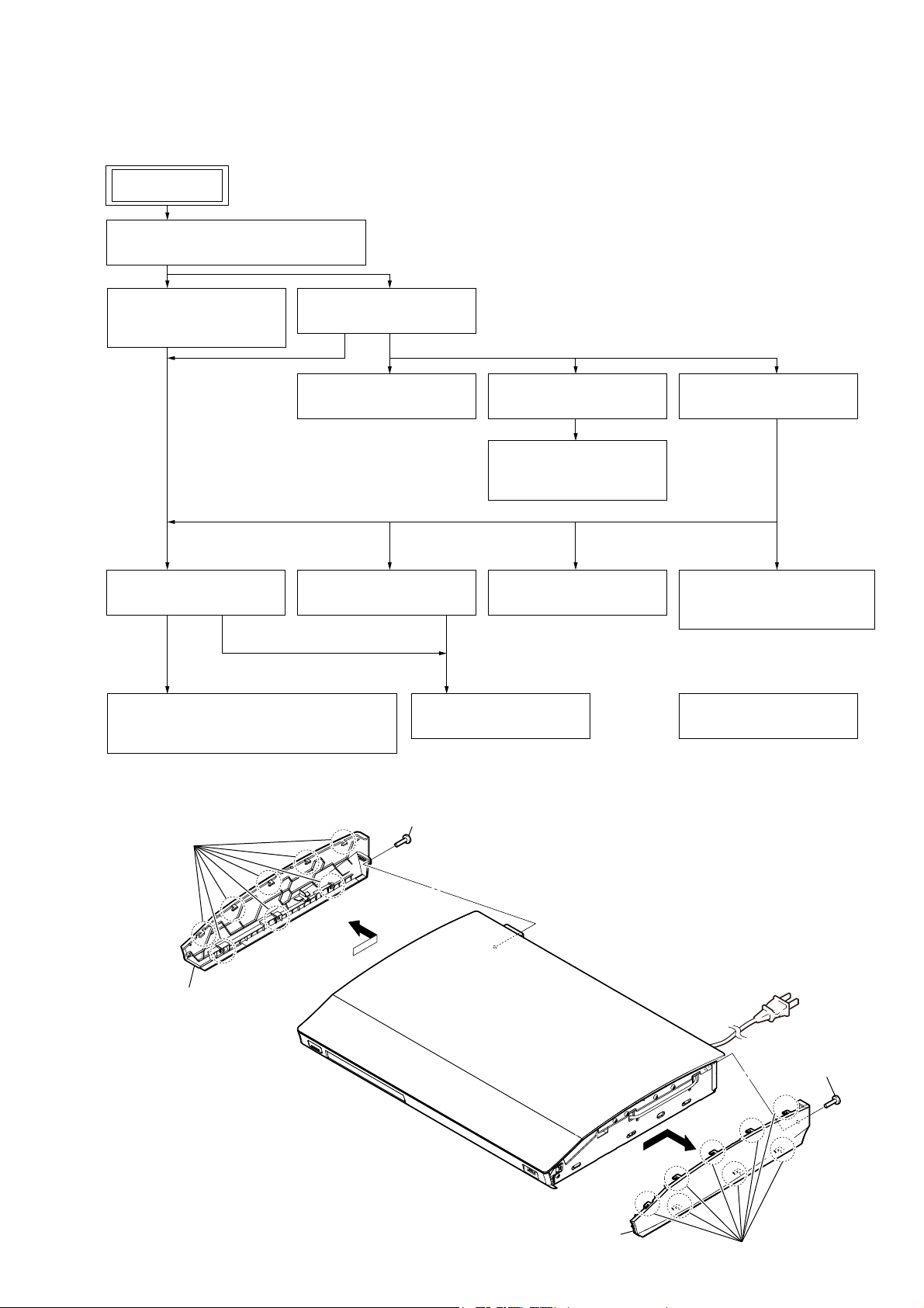
DESMONTAGEM
• This set can be disassembled in the order shown below.
2-1. FLUXO DE DESMONTAGEM
SET
2-2. LEFT PANEL (E1), RIGHT PANEL (E1)
(Page 11)
SECTION 2
HBD-E780W/E980W/E985W
Ver. 1.2
2-3. LOADING PANEL ASSY
(E1)
(Page 12)
2-9. BD DRIVE (BPX-6)
(Page 15)
2-14. OPTICAL PICK-UP BLOCK (KEM-470AAA),
WIRE (FLAT TYPE)
(Page 19)
2-4. TOP PANEL BLOCK
(Page 12)
2-5. FL BOARD
(Page 13)
2-10. WS BOARD
(Page 15)
2-6. FRONT PANEL BLOCK
(Page 13)
2-7. WIRELESS LAN CARD
(WLC1) (E780W/E980W)
(Page 14)
2-11. AMP BOARD
(Page 16)
2-13. MB-141 BOARD
(Page 18)
2-8. TOP LID BLOCK
(Page 14)
2-12. SWITCHING REGULATOR
(SWR1)
(Page 17)
2-15. HOW TO BEND FFC
(Page 20)
Note: Follow the disassembly procedure in the numerical order given.
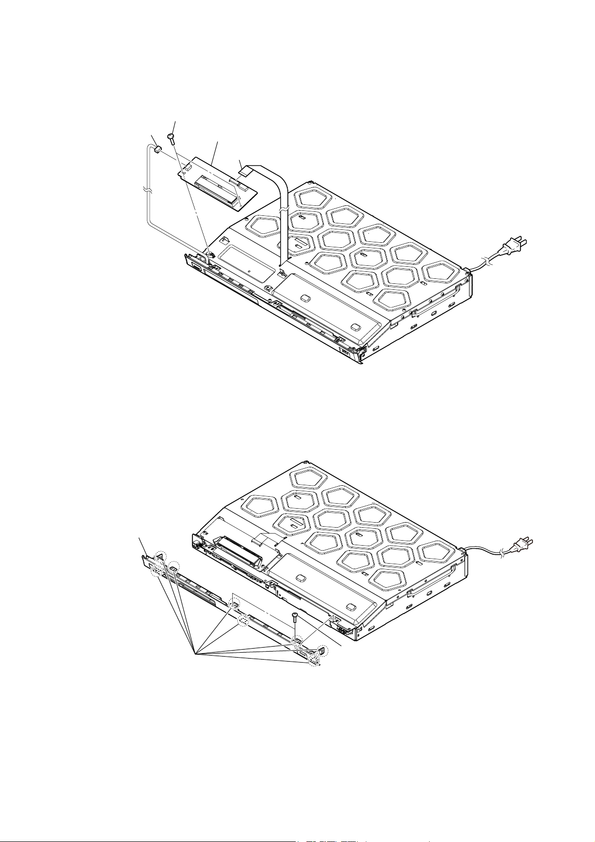
2-2. LEFT PANEL (E1), RIGHT PANEL (E1)
1 screw (BV3)
2 eight claws
3
4 left panel (E1)
1 screw (BV3)
3
4 right panel (E1)
2 eight claws
11
HBD-E780W/E980W/E985W
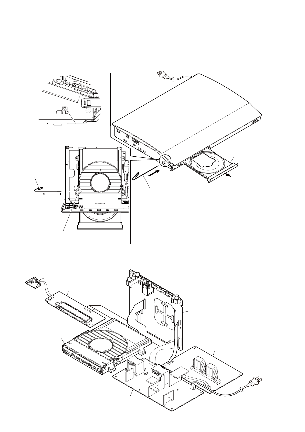
2-3. LOADING PANEL ASSY (E1)
hole
– Side view –
4 loading panel
assy (E1)
Insert the clip etc.
processed to the
length of 8 cm or
more in the hole
on the side of the
chassis and push.
8 cm or more
Push after it inserts it in this hole well.
Note:
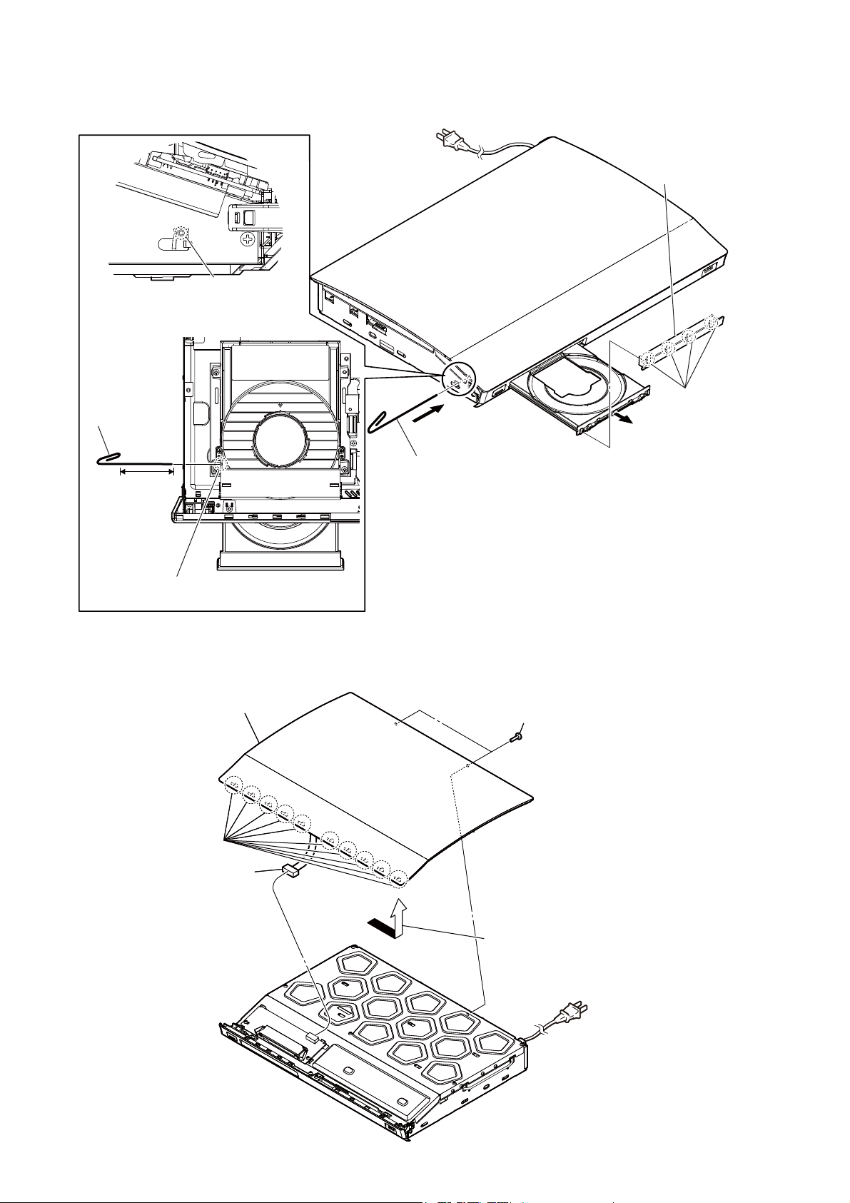
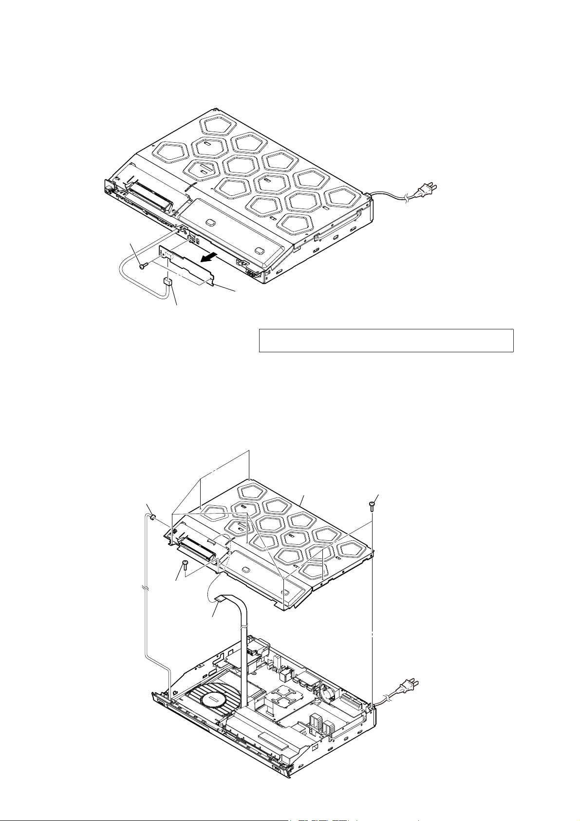
2-4. TOP PANEL BLOCK
5 top panel block
5 top panel block
BD drive
tray
– Top view –
1 Insert the clip etc.
1 two screws (BV3)
1 two screws (BV3)
3 four claws
2
12
2 ten claws
2 ten claws
4 connector
4 connector
(CN03)
(CN03)
3 Lift after doing the slide in
the direction of the arrow.
2-5. FL BOARD
2 connector
(CN01)
HBD-E780W/E980W/E985W
3 two screws
(BV3)
4 FL board
1 wire (flat type) (19 core) (CN02)
2-6. FRONT PANEL BLOCK
3 front panel block
2 eight claws
1 two screws
(BV3)
13
HBD-E780W/E980W/E985W
Ver. 1.2
2-7. WIRELESS LAN CARD (WLC1) (E780W/E980W)
1 two screws
(BV3)
2
4 wireless LAN card
3 harness (USB)
(WLC1)
2-8. TOP LID BLOCK
2 connector
(CN01)
3 screw
(BV3)
Note: When replacing the wireless LAN card (WLC1), refer to “CHECKING
METHOD OF NETWORK OPERATION” (page 9).
5 top lid block
4 seven screws
(BV3)
14
1 wire (flat type)
(19 core) (CN02)
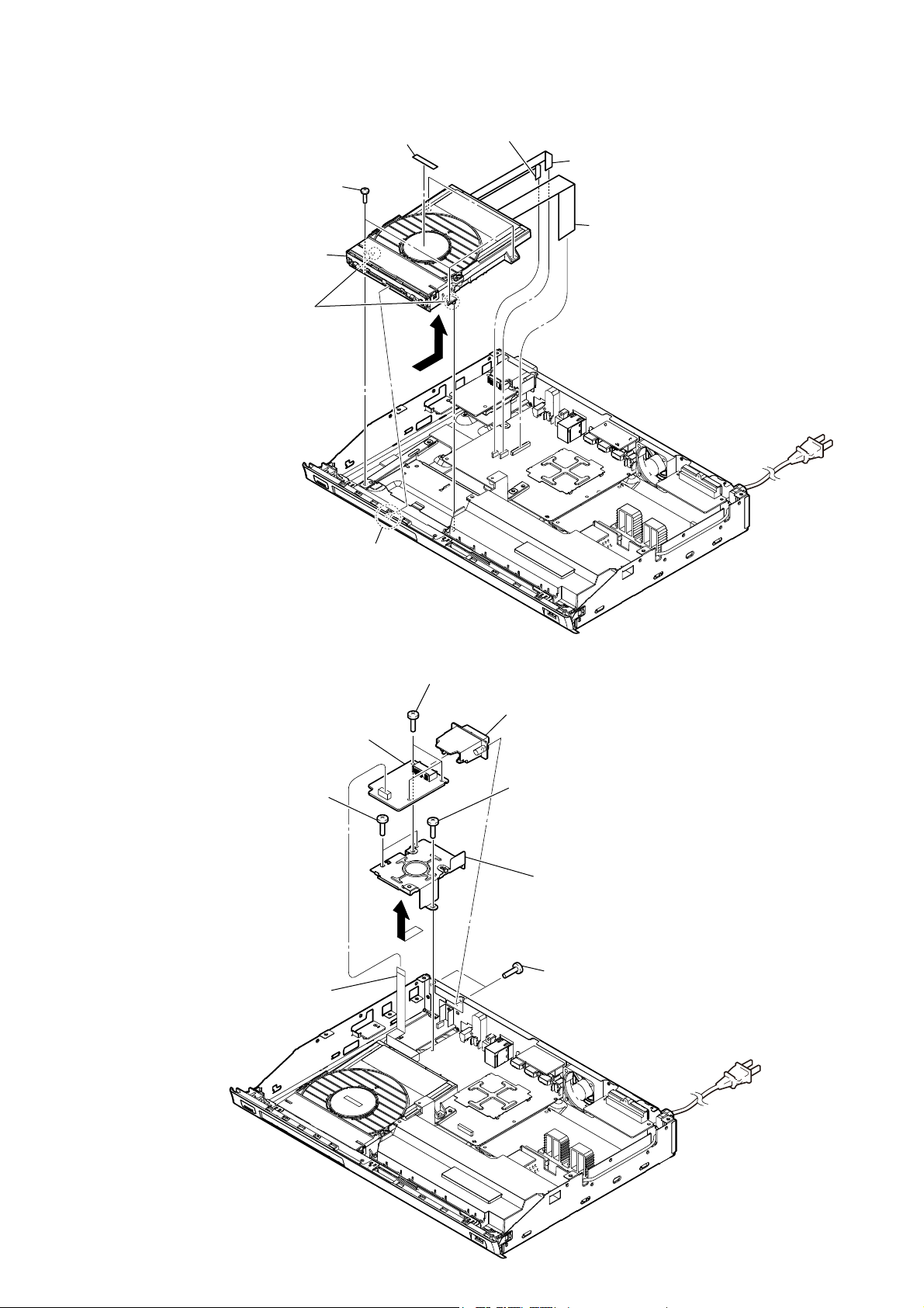
2-9. BD DRIVE (BPX-6)
4 four screws
(BV3)
8 BD drive (BPX-6)
When you install the BD
Note:
drive (BPX-6), please match
the position of the boss two
places.
7 sound sheet
6
HBD-E780W/E980W/E985W
3 wire (flat type) (5 core) (CN2470)
2 wire (flat type) (9 core) (CN2460)
1 wire (flat type) (45 core) (CN1301)
2-10. WS BOARD
1 wire (flat type) (13 core)
(CN55)
8 WS board
3 two screws
(BV3)
5 boss
6 three screws
(BV3)
5 slot card (WS)
3 screw (BV3)
7 bracket (WS)
4
2 two screws
(BV3)
15
HBD-E780W/E980W/E985W
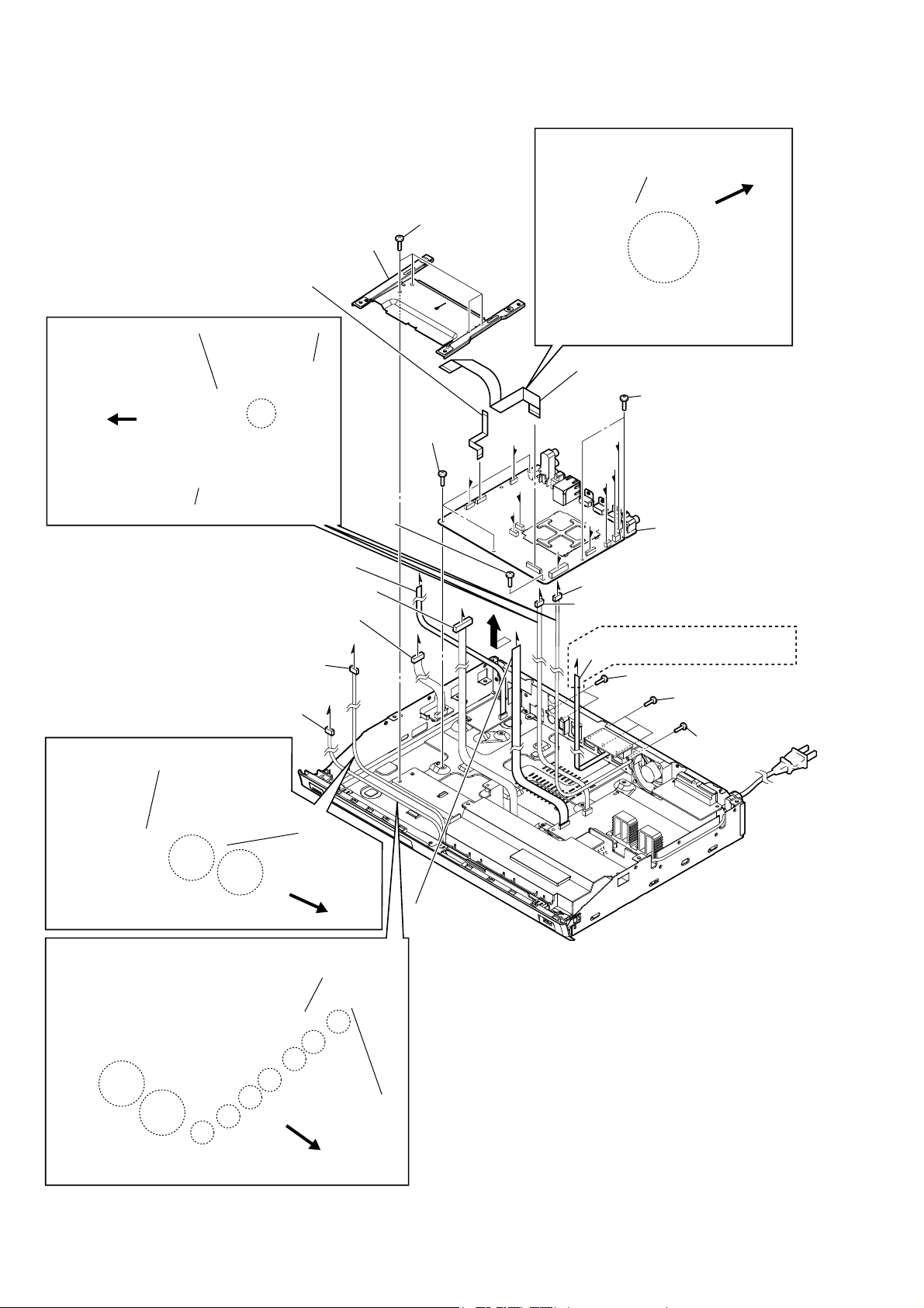
2-11. AMP BOARD
:LUHVHWWLQJ
:LUHVHWWLQJ
rear side
power insulated
(lower-E1)
fan cable
MB-141 board
front side
switching
regulator
(SWR1)
AMP board
4 connector
(CN5302)
3 wire (flat type)
(24 core) (CN3004)
7 screw (BV3)
2 connector
(CN101)
5 three screws
(BV3)
8 four screws
(BV3)
6 heat sink
(S-master DDV)
1 connector
(CN451)
Twist wire
three times.
AMP board
9 AMP board
16
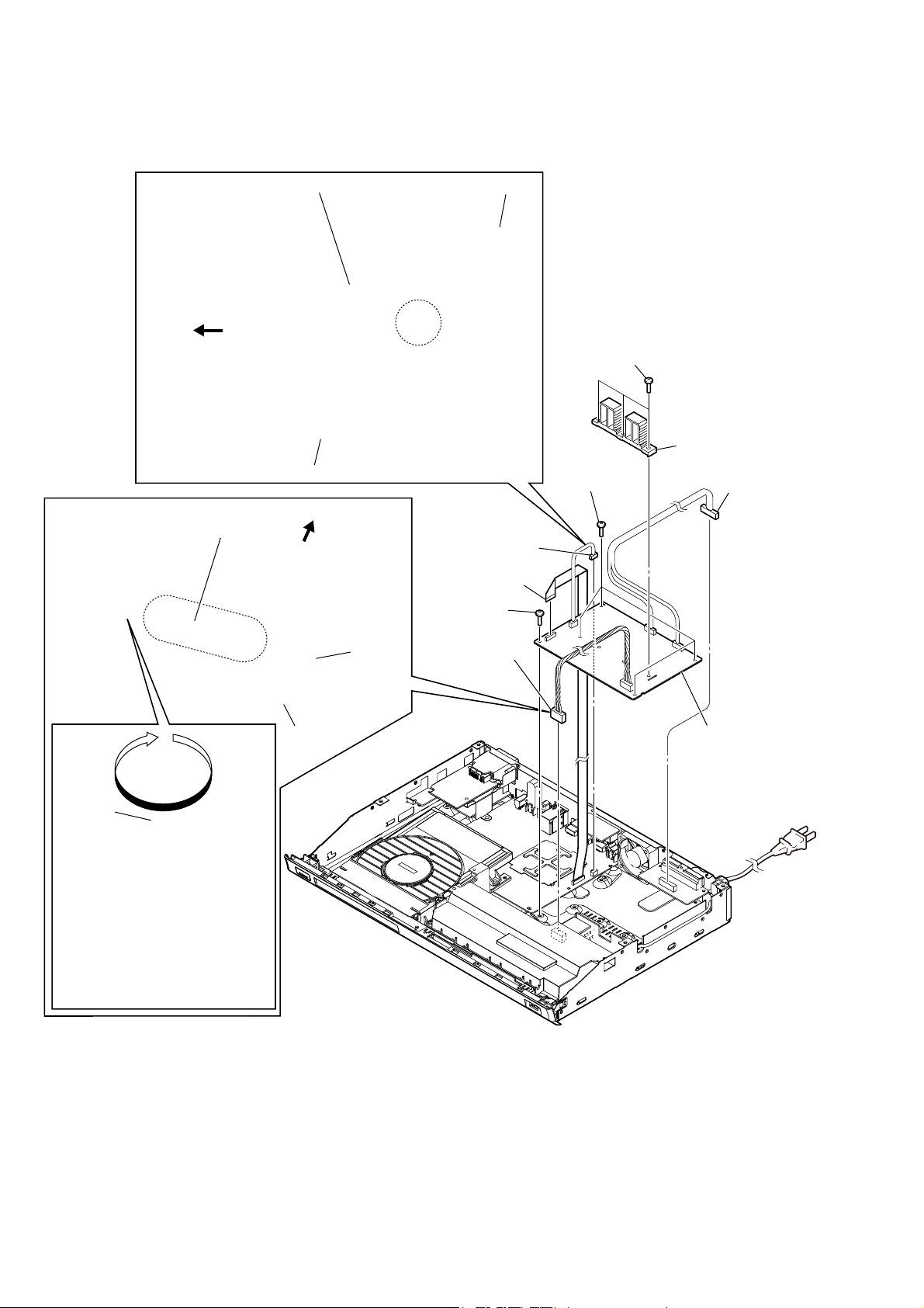
2-12. SWITCHING REGULATOR (SWR1)
:LUHVHWWLQJ
HBD-E780W/E980W/E985W
2 four screws
(BV3)
3 power insulated
(upper-E1)
Twist wire
three times.
7 seven screws
(BV3)
8 switching regulator
(SWR1)
1 harness (USB) (CN602)
6 connector
(CN301)
power insulated
(lower-E1)
switching
regulator
(SWR1)
5 connector
(CN101)
4 power cord connector
(CN1)
front side
AMP board
:LUHVHWWLQJ
power insulated
(upper-E1)
harness (USB)
front side
rear side
3RZHUFRUGVHWWLQJ
switching
regulator
(SWR1)
17
HBD-E780W/E980W/E985W
Ver. 1.2
2-13. MB-141 BOARD
WLUH VHWWLQJ
power
insulated
(lower-E1)
WLUH VHWWLQJ
rear side
WLUH VHWWLQJ
qk wire (flat type)
(13 core) (CN5904)
fan cable
MB-141 board
3 harness (USB)
(CN602)
harness (USB)
2 drive bracket
AMP board
8 wire (flat type)
(7 core) (CN5909)
qa connector (CN5301)
7 connector
(CN5102)
4 harness (USB)
(CN603)
A
qf screw
(BV3)
B
1 four screws
(BV3)
qg six screws
(BV3)
E
F
I
E
qh
A
B
F
G
H
qj wire (flat type) (19 core) (CN6201)
qg two screws
(BV3)
C
D
H
G
I
6 fan connector (CN6501)
D
0 connector (CN5302)
C
5 wire (flat type) (5 core) (CN6001)
ql MB-141 board
(US, CND, AUS, SP, TW, TH)
qd two screws (BV3)
qs three screws
(B3 u 5)
qd screw (BV3)
front side
WLUH VHWWLQJ
18
power
insulated
(lower-E1)
front
side
power insulated
(upper-E1)
harness (USB)
front side
9 wire (flat type)
(24 core) (CN5907)
• Abbreviation
AUS : Australian model
CND : Canadian model
SP : Singapore model
TH : Thai model
TW : Taiwan model
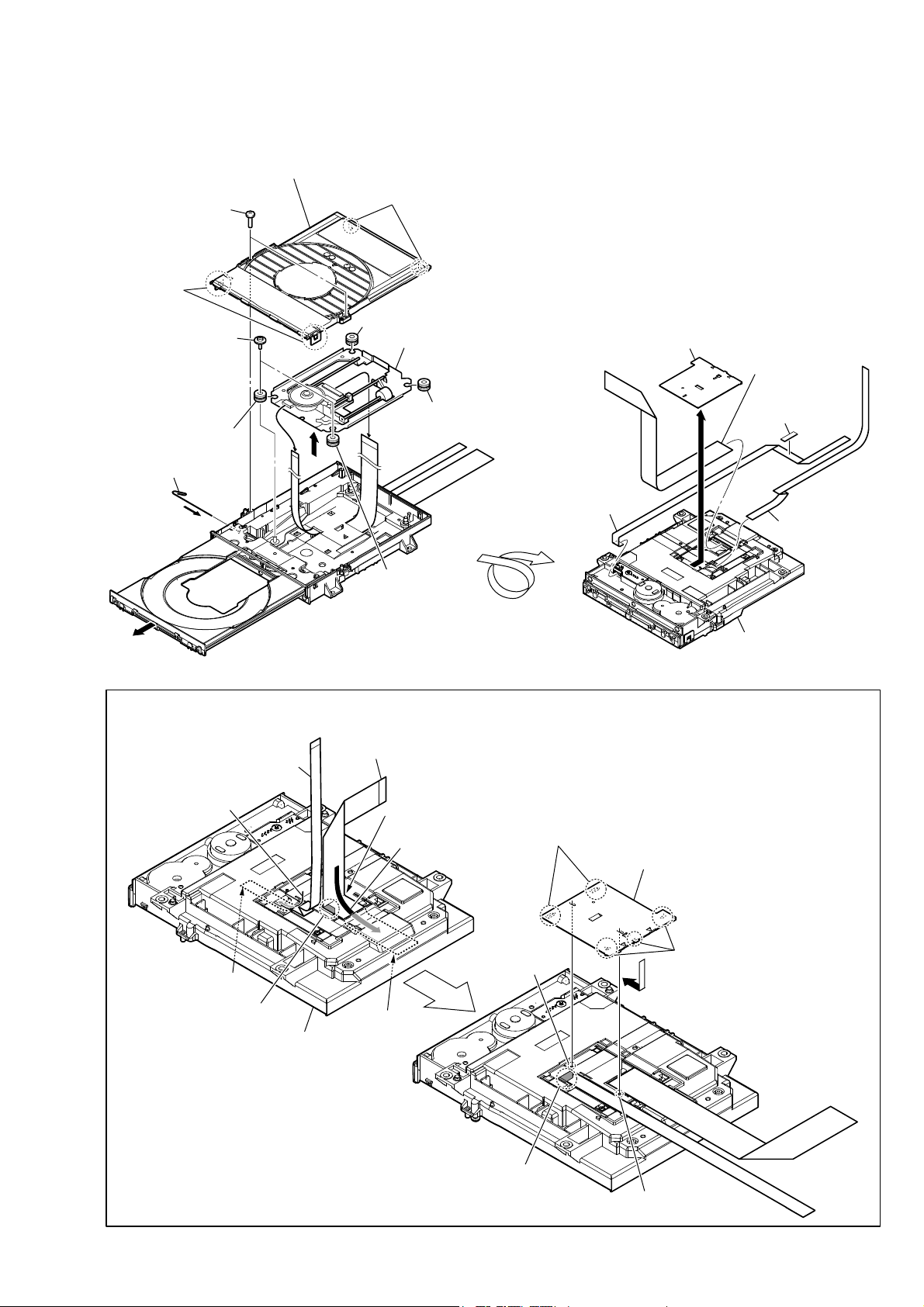
2-14. OPTICAL PICK-UP BLOCK (KEM-470AAA), WIRE (FLAT TYPE)
4 chuck holder assy (D)
1 two screws
(BVTP 2.6)
2 two claws
7 two float screws (S)
qa insulator
5 Insert the thin
wire (clip etc.).
8
0
3 two claws
qa insulator
qs optical device
(KEM-470AAA)
qa insulator
9
HBD-E780W/E980W/E985W
qh FFC holder (rear)
qk wire (flat type)
(45 core)
qd non-halogene
tape
qg
qf wire (flat type) (5 core)
qa insulator
6
,QVWDOODWLRQRIZLUHIODWW\SHFRUHDQGZLUHIODWW\SHFRUH
This illustration sees the loading assy (D) from bottom side.
Note:
3 wire (flat type) (9 core)
4 Through the hole.
terminal face
1 wire (flat type) (45 core)
Fold
2 Through the hole.
boss
qj wire (flat type)
(9 core)
loading assy (D)
– Bottom view –
7 two claws
5 FFC holder (rear)
7 three claws
6
Under the guide.
loading assy (D)
terminal face
Under the guide.
(Fold area)
boss
19
HBD-E780W/E980W/E985W
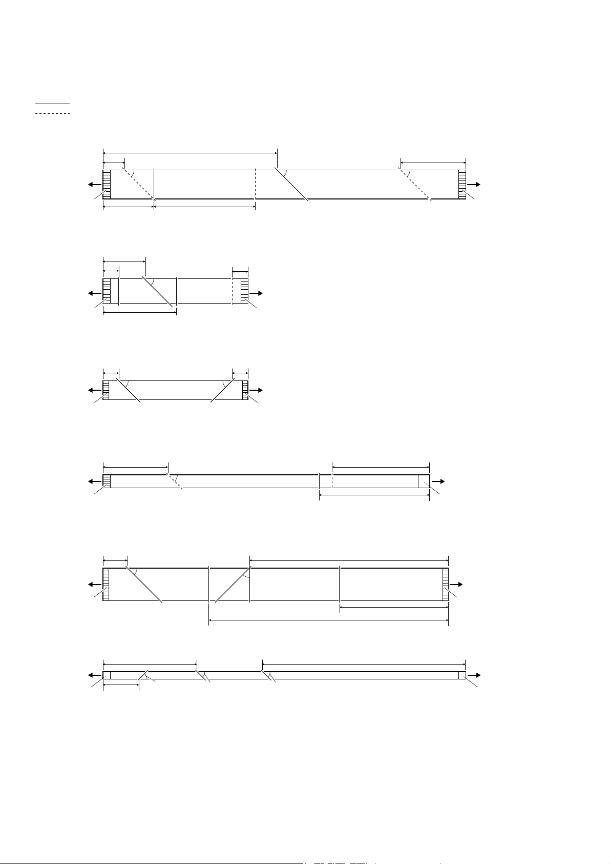
2-15. COMO DOBRAR O CABO FLAT FFC
: Mountain fold
: Valley fold
ZLUHIODWW\SHFRUHOHQJWKPP5HI1R
120 mm
15 mm
MB-141 board
(CN6201)
The upper side
is contact side.
ZLUHIODWW\SHFRUHOHQJWKPP5HI1R
MB-141 board
(CN5904)
The upper side
is contact side.
45º
35 mm 70 mm
35 mm
11 mm
45º
50 mm
11 mm
45º 45º
WS board
(CN55)
The upper side
is contact side.
45 mm
FL board
(CN02)
The upper side
is contact side.
ZLUHIODWW\SHFRUHOHQJWKPP5HI1R
MB-141 board
(CN5907)
The upper side
is contact side.
ZLUHIODWW\SHFRUHOHQJWKPP5HI1R
MB-141 board
(CN2460)
The upper side
is contact side.
ZLUHIODWW\SHFRUHOHQJWKPP5HI1R
MB-141 board
(CN1301)
The upper side
is contact side.
ZLUHIODWW\SHFRUHOHQJWKPP5HI1R
MB-141 board
(CN2470)
The lower side
is contact side.
11 mm 11 mm
45º
45 mm 67 mm
17 mm
45º
65 mm 140 mm
25 mm
45º
45º
45º
45º
45º
AMP board
(CN3004)
The upper side
is contact side.
45º
137 mm
165 mm
76 mm
75 mm
BD drive
(BPX-6)
The lower side
is contact side.
BD drive
(BPX-6)
The upper side
is contact side.
BD drive
(BPX-6)
The lower side
is contact side.
20
SECTION 3
MODO DE TESTE
HBD-E780W/E980W/E985W
COLD RESET
The cold reset clears data except BD/DVD data stored in the RAM
to initial conditions. Execute this mode when returning the unit to
the customers.
Procedure:
1. Press the [
] button to turn the power on.
?/1
2. Touch the [x] and [VOL –] sensors simultaneously and hold
down (around 5 seconds).
3. The message “RESET” appears on f uorescent indicator tube,
then becomes standby states.
DEMO MODE
This mode let you lock the disc tray. When this mode is activated,
the disc will not eject when the [
] sensor is touched. The mes-
Z
sage “DEMO LOCK” will be displayed on the fluorescent indicator tube.
Procedure:
1. Press the [
] button to turn the power on.
?/1
2. Touch the [FUNCTION] sensor to select the “BD/DVD”.
3. Touch the [x] and [Z] sensors simultaneously and hold down
until “DEMO LOCK” or “DEMO OFF” displayed on the fluorescent indicator tube (around 5 seconds).
Releasing method:
Touch the [x] and [Z] sensors simultaneously and hold down until
“DEMO OFF” displayed on the f uorescent indicator tube (around
5 seconds).
FACTORY INITIALIZE
Return all of the unit setting to their factory defaults.
Note 1: Disconnect the following connections when you use this mode.
• Front USB
• Rear USB
• LAN
• HDMI IN 1
• HDMI IN 2
Note 2: The operation in this mode must use a remote commander and TV
monitor.
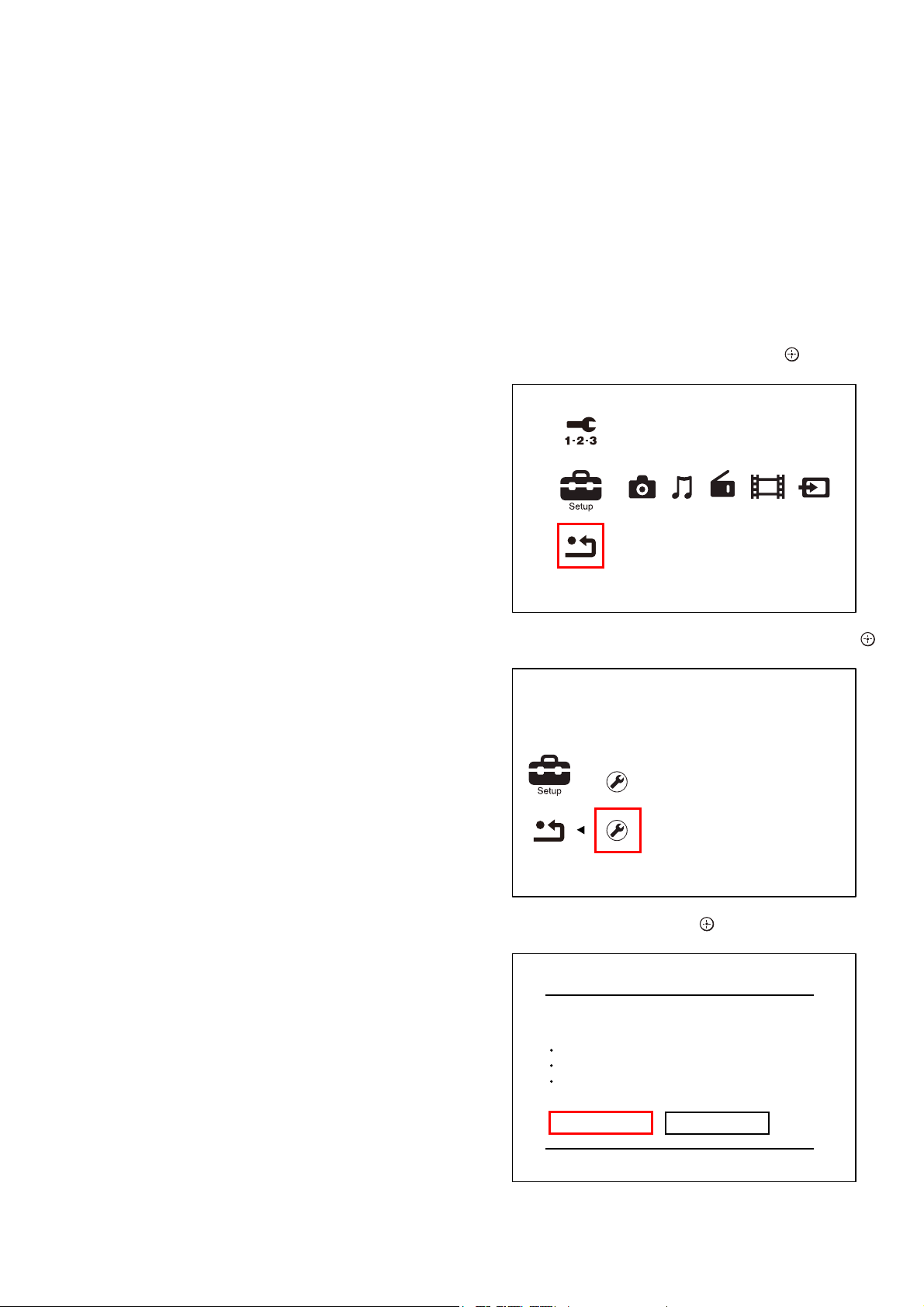
Procedure:
1. Press the [
] button to turn the power on.
?/1
2. Press the [HOME] button on the remote commander, and the
home menu is displayed.
3. Select “Setup” → “Resetting”, and press the [
] button on the
remote commander.
Easy Setup
Resetting
PANEL TEST
Procedure:
1. Press the [
] button to turn the power on.
?/1
2. Press button in order of the [DISPLAY] → [0] → [0] → [1]
→ [SUBTITLE] on the remote commander (Make the interval
when each button is pressed within two seconds).
3. All segments in f uorescent indicator tube are lighted up. And
half segments in f uorescent indicator tube are lighted up, others half segments in f uorescent indicator tube are lighted up,
then all segments in f uorescent indicator tube are lighted up.
This operation is repeated.
4. When all segments in f uorescent indicator tube are lighted up
in the state of step 3, press the [VOL +] button on the remote
commander and model information is displayed on the f uorescent indicator tube.
Each time the [VOL +] button on the remote commander is
pressed, the display changes from destination information,
STR version in this order, and returns to the model information display.
Each time the [VOL –] button on the remote commander is
pressed, the version and date are switched.
5. In the state of step 3, press the [FUNCTION] button on the
remote commander and “K 0” is displayed on the fluorescent
indicator tube.
“K 0” value increases whenever a button or sensor on the unit
is pressed. However, once a button or sensor has been pressed,
it is no longed taken into account.
All button and sensors on the unit are pressed, “OK” and “K 7”
are alternately displayed on the fluorescent indicator tube.
Releasing method:
To release from this mode, press the [
?/1
] button.
4. Select “Initialize Personal Information”, and press the [ ]
button on the remote commander.
Reset to Factory Default Settings
Initialize Personal Information
Erase personal data when disposing
5. Select “OK”, and press the [ ] button on the remote commander.
Initialize Personal Information
The information below will be deleted.
Do you want to proceed?
Playback history
Internet video utilization information
Internet content registered as Favorites
OK
Cancel
21
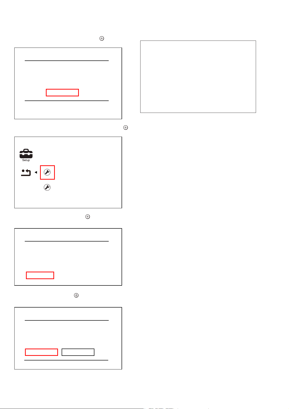
HBD-E780W/E980W/E985W
6. The message “Close” appears, and press the [
] button on the
remote commander.
Initialize Personal Information
Initialization complete.
Close
7. Select “Reset to Factory Default Settings”, and press the [ ]
button on the remote commander.
Reset to Factory Default Settings
Restore each setting to the factory d
Initialize Personal Information
8. Select “All Settings”, and press the [ ] button on the remote
commander.
Reset to Factory Default Settings
BD/DVD Viewing Settings
Personal Control Settings
Music Settings
System Settings
Network Settings
All Settings
BD SERVICE MODE
[Wireless checking fail on M07.R.179]
Due to software bug in M07.R.179, currently Service mode do not support wireless checking features this version of software.
For service to conf rm the wireless checking, please update customer
sets to latest version of software. By using network upgrade method
or Disc upgrade method. After f nish upgraded, Service member can
perform wireless checking as mention in wireless LAN checking pages.
Or
Conf rm wireless LAN connection from customer mode, in case of
Wireless connection successfully establish. The wireless Lan network
connection will be judge as OK.
Date: 26 January 2011
Note: The operation in this mode must use a remote commander and TV
monitor.
Setting method of the BD service mode:
1. Connect this unit with TV monitor.
2. Press the [
] button to turn the power on.
?/1
3. Press button in order of the [DISPLA Y] → [0] → [2] → [1] →
[SUBTITLE] on the remote commander. (Make the interval
when each button is pressed within two seconds)
4. Enter the BD service mode. The OSD menu on TV monitor
can be operated by remote commander.
1. Main Functions
• Diag
Performs unit test of devices installed on the board.
• Display Error Log
Error log is displayed. Displayed contents can also be saved in
an USB memory device.
• Factory Initialize
Restores the unit to its factory settings.
• Network
Checks the wired network connection.
• Version Up
Not used.
• System Information
Displays the system information of the unit.
Displays information such as the software version, drive infor -
mation, etc.
• EMC Test Mode
Not used.
• Drive
Write drive OP data and check drive.
9. Select “Start”, and press the [ ] button on the remote commander.
All Settings
Restore all settings to the factory default
settings. The system will turn off after
reset.
Start
Cancel
10. Initialization ends when the message “WELCOME” on the
f uorescent indicator tube disappears.
22
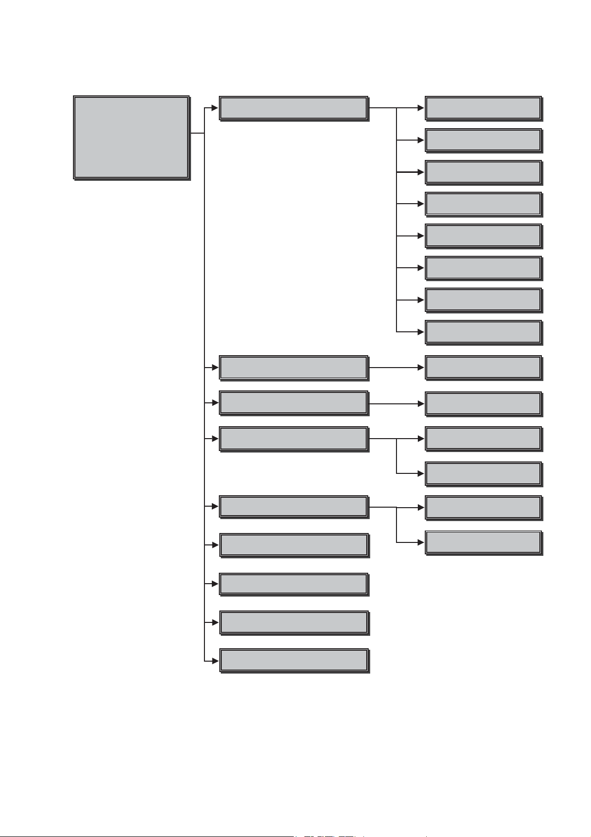
2. Menu Tree
HBD-E780W/E980W/E985W
Service Mode Menu
Service Mode Menu
[1] Diag
[1] Diag
[2] Log
[2] Log
[3] Factory Initialize
[3] Factory Initialize
[4] Network
[4] Network
[5] Version Up
[5] Version Up
[6] System Information
[6] System Information
[7] EMC Test Mode
[8] Drive
[9] HDD Mode
Diag
Diag Test
Log
Displays Error Log
Device Test
US%D$CIFcon test
Video Test
Video output test
$udio Test
$udio output test
$udio Input Test
$udio Input Test
:ireless L$N Test
Not used
Mic Test
Not used
HDMI Input Test
HDMI Input Test
Transcoder Test
Not used
Error Log
Displays error log
Factory Initialize
Initialize default setting
Network
Network diagnosis for wired
Version Up
Not used
System Information
Displays system information
EMC Test Mode
Not used
Drive
Write drive OP data and check drive
HDD Mode
Not used
Start Initialize
Initialize default setting for the unit
Ifconfig
View network status
Ping
Confirm network connection
Start Update for %DP
Not used
Start Update for %DV
Not used
23
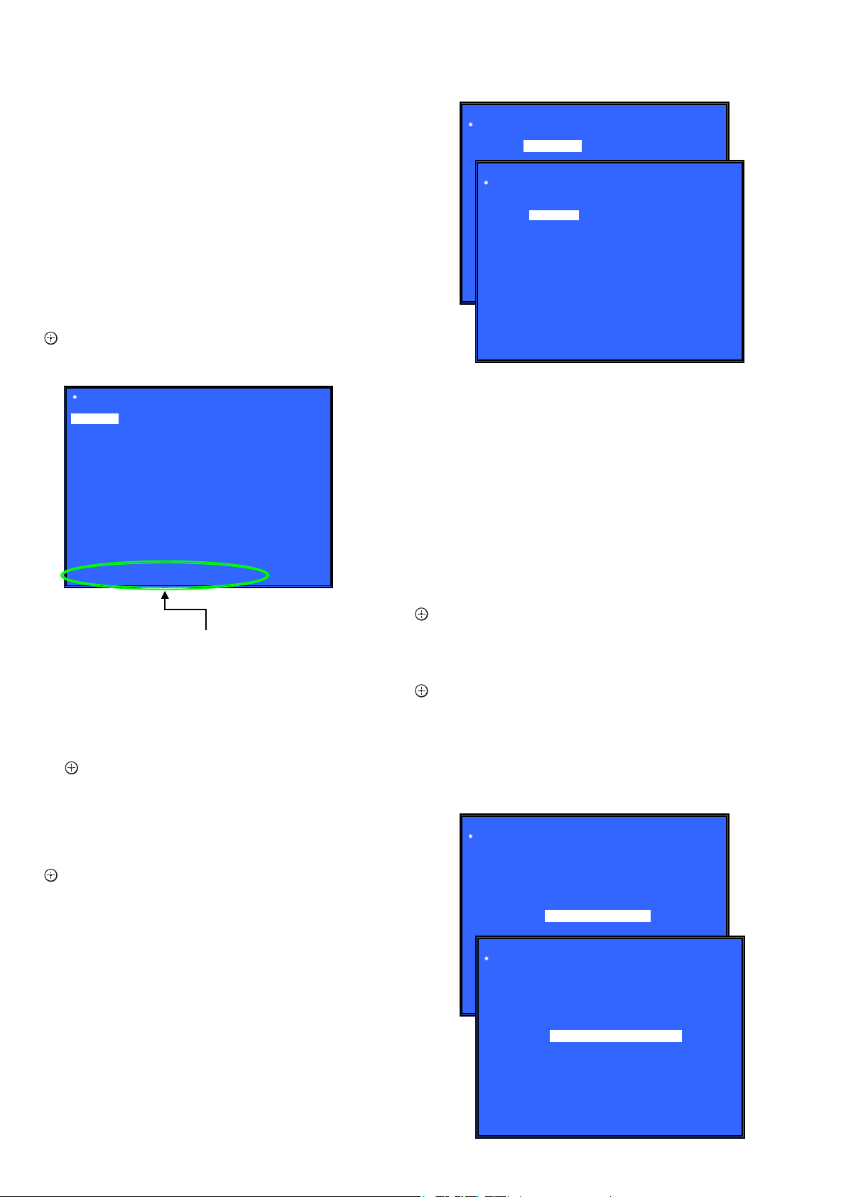
HBD-E780W/E980W/E985W
3. Service Mode Menu (Top Menu)
This is the top menu of service mode.
Each function is accessed from this screen.
Operation:
[1] Moves to Diag screen
[2] Moves to Log screen
[3] Moves to Factory Initialize screen
[4] Moves to Network screen
[5] Moves to Version Up (DISC version update) screen (Not
used)
[6] Moves to System Information screen
[7] Moves to EMC test mode screen (Not used)
[8] Moves to Drive screen
[9] Moves to HDD mode (Not used)
[M]/[m] Moves the cursor
[ ] Moves to the screen of the item selected with the cursor
* Cursor is not displayed when the menu is f rst displayed.
Service Mode Menu
[1] Diag
[1] Diag
[2] Log
[3] Factory Initialize
[4] Network
[5] Version Up
[6] System Information
[7] EMC Test Mode
[8] Drive
[9] HDD mode
Diag
Device Test
Category: Device Test
USB Host
Device:
Rear USB Media check ... OK
Front USB Media check ... OK
Checking...
(Screen 1)
(Screen 2)
Category:
Diag
HELP: [RIGHT] [UP] [ENT] [RET]
• Device Test: List of devices
USB Host : USB media check (front and rear). Only one time.
D/A Converter : DAC write check (non-verif cation).
Ifcon : Not used in this unit.
MIC : Not used in this unit.
MFI : MFI read/write Check
IPC : Device ID check
External HDMI : Revision check
Transcorder : Not used
HELP : [DOWN] [ENT] [(NUM)]
HELP (currently available keys, etc.) is displayed
4. Diag (Device Test)
This screen is used to test devices mounted on the board.
Screen 1: Selects the test category
Operation:
[<]/[,] Selects the category
[m]/[ ] Moves to the selected category
[RETURN] Returns to the service top menu
Screen 2: Device test
Selects the device to test after selecting Device Test in screen 1.
Operation:
[<]/[,] Selects the device to test
[ ] Executes the test
[M] Returns to selection of test category
[RETURN] Returns to selection of test category
• List of test categories
Device Test
Video Test
Audio Test
Audio Input Test
Wireless LAN Test (not used)
Mic Test (not used)
HDMI Input Test
Transcoder Test (not used)
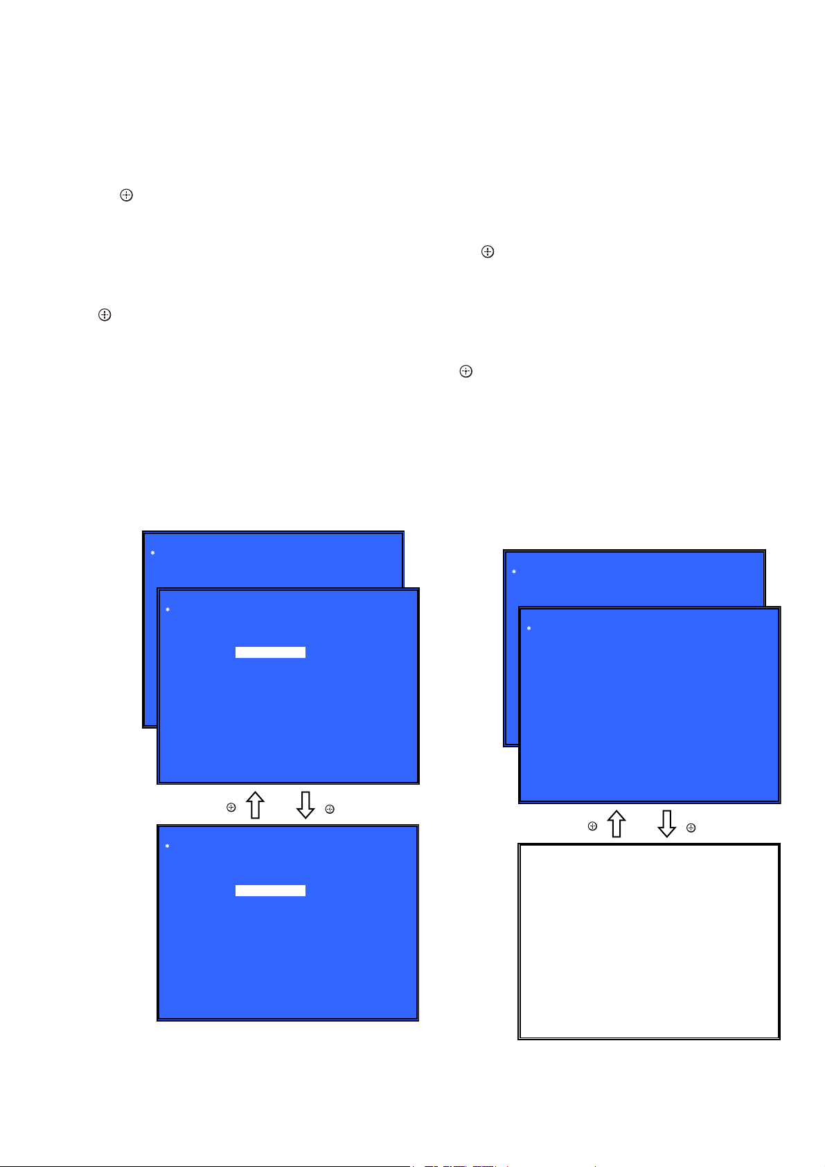
5. Diag (Video/Audio Test)
This screen performs video and audio tests.
Screen 1: When video test category is selected
Operation:
[ ] Shows/hides the color bar
]/[RETURN] Returns to the selection of test category
[
M
Screen 2: When audio test category is selected
Operation:
[
] Plays back/stops the tone sound
]/[RETURN] Returns to the selection of test category
[
M
• Video test:
Outputs a color bar (composite & component & HDMI).
• Audio test:
TONE sound output (speaker & HDMI).
Diag
Category: Video Test
[ENT] Show Color Bar
Diag
Category: Audio Test
(Screen 1)
HELP: [UP][ENT][RET]
[ENT] Generate TONE Sound
24
(Screen 2)
HELP: [UP] [ENT] [RET]
HBD-E780W/E980W/E985W
Ver. 1.2
6. Diag (Audio Input Test)
This screen performs audio input test.
Screen 1: Select Audio Input Test Category
Operation:
[<]/[,] Selects the category
[m]/[ ] Activate the selected category
[RETURN] Returns to the service top menu
Screen 2: Select Input Device
After “Audio Input Test” selects in Screen 1, the device to test is
chosen.
Operation:
[M]/[m] Selects Device
[ ] Activate and Start Test/Stop
[RETURN] Returns to the selection of test category
• Device Test : Device List
Digital Input1 : CXD9998 is inputted from ARC
Digital Input2 : CXD9998 is inputted from Optical
Analog Input : CXD9998 is inputted from AUDIO
• Audio Input Test
CXD9998 is inputted from DIR/analog and outputs LineOut (8ch)
L and R.
Check tone sound by speaker connected with LineOut (8ch) L and
R.
(Input; LPCM 48kHz 2ch)
Diag
Category:
Diag
(Screen 1)
Audio Input Test
Category: Audio Input Test
Device:
[ENT] Start Input Sound
Digital Input 1
Digital Input 2
Analog Input
8. Diag (MIC Input Test)
This screen performs MIC input test.
Note: Not used for the servicing.
9. Diag (HDMI Input Test)
This screen performs HDMI input test.
Screen 1: Select HDMI Input Test Category
Operation:
[<]/[,] Selects the category
] Activate the selected category
[m]/[
[RETURN] Returns to the service top menu
Screen 2: Select Input Device
After “HDMI Input Test” selects in Screen 1, the device to test is
chosen.
Operation:
[M]/[m] Selects Device
] Activate and Start Test/Stop
[
[RETURN] Returns to the selection of test category
• Device Test : Device List
HDMI Input1 : CXD9998 is inputted from HDMI1
HDMI Input2 : CXD9998 is inputted from HDMI2
• HDMI Input Test
Path test from HDMI to HDMI through CXD9998.
CXD9998 is selected and inputted HDMI IN and outputs HDMI
OUT.
Check Video and Audio by TV/AMP connected with HDMI.
Diag
Category:
(Screen 1)
HDMI Input Test
Diag
Category: HDMI Input Test
[1] HDMI Input1 Test
[2] HDMI Input2 Test
(Screen 2)
HELP: [LEFT] [RIGHT] [UP] [DOWN] [ENT] [RET]
[ ]
Diag
Category: Audio Input Test
Device:
[ENT] Stop Input Sound
HELP: [LEFT] [RIGHT] [UP] [DOWN] [ENT] [RET]
Digital Input 1
Digital Input 2
Analog Input
[ ]
7. Diag (Wireless LAN Test) (HBD-E780W/E980W only)
This screen performs wireless LAN test.
Note: This mode doesn’t operate correctly. Never use this mode. Refer to
“CHECKING METHOD OF NETWORK OPERATION” on page
9 when you conf rm the wireless LAN operation.
(Screen 2)
HELP: [UP] [ENT] [RET]
[ ]
The video and audio connected with
HDMI1 or HDMI2 are outputted to TV monitor
HELP: [LEFT] [RIGHT] [UP] [DOWN] [ENT] [RET]
10. Diag (Transcoder Test)
Note: Not used for the servicing.
[ ]
25

HBD-E780W/E980W/E985W
11. Log: Error Log (Output of each Log)
This screen displays the contents of each log.
Note: Do not refer to the displayed date.
Screen 1: Selects log
Operation:
[1]/[ ] Moves to the Error Log output screen
[RETURN] Returns to the top menu of the service mode
Screen 2: Displays the Error Log
Operation:
[
] Returns to the previous page
<
[,] Moves to the next page
[RETURN] Returns to the screen (Screen 1) that selects the log
type
[RED] Writes the log contents to an USB memory device
• Viewing the log display
Error Log:
08/01/01 00: 53: 19: [ErrCode: 080400000000]
[Date] [Time] [Error code]
About copying log to USB memory device:
Press the [RED] button in each log display screen with the USB
memory device inserted into the unit.
Note: Please do not press the [RED] button immediately after USB mem-
ory is inserted.
Please do not pull out USB memory immediately after the [RED]
button was pressed.
Error Log:
When “getErrLogFile.trm f le” exists in the USB memory de-
vice, errlog.log f le is output.
Select Log
[1] Error Log
13. Network (Network Test Diagnosis Screen: Ifconf g)
Network menu for the wired ethernet.
Screen 1: Ifconf g Test
Operation:
] Activate Ifconf g (Display network setting)
[
[,] Select ping test
[RETURN] Returns to the top menu of the service mode
Screen 2: Ping Test
Operation:
[<] Select Ifconf g test
[RETURN] Returns to the top menu of the service mode
(The details of a Ping test are “14. Network (Network T est Diagnosis Screen: Ping)”)
Screen 3: Ifconf g Test Active
Display Ifconf g command results.
Operation:
[ ] Ifconf g retry
[,] Select Ping Test
[RETURN] Returns to the top menu of the service mode
Network
Test: Ifconfig Ping
Network
Test: Ifconfig Ping
Ping To:
[START]
Network
(Screen 1)
HELP : [DOWN][ENT][(NUM)]
Test: Ifconfig Ping
IP 192. 168. 11. 2 MAC 00-16-01-85-21-A3
Error Log
08/01/01 00: 53: 19: [ErrCode: 080400000000]
08/01/01 00: 53: 45: [ErrCode: 080400252100]
(Screen 1)
(Screen 2)
08/01/01 00: 54: 00: [ErrCode: 080400005555]
HELP : [DOWN][ENT][(NUM)]
:
:
12. Factory Initialize (Factory Settings)
There is a possibility that this mode cannot be correctly executed. Never use this mode.
(Screen 2)
(Screen 3)
HELP : [DOWN][ENT][(NUM)]
HELP : [ENT]: Re/Exe [RIGHT]
26
 Loading...