

Sony HBDE-770-W Service manual
HBD-E770W
SERVICE MANUAL
Ver. 1.0 2010.02
• HBD-E770W is the amplifi er, video, BD/DVD/Super Audio
CD/CD system, USB, LAN and tuner section in BDV-E770W.
• This product incorporates copyright
protection technology that is protected by
U.S. patents and other intellectual property
rights.
Use of this copyright protection technology
must be authorized by Macrovision, and is
intended for home and other limited viewing uses only unless otherwise authorized
by Macrovision.
Reverse engineering or disassembly is
prohibited.
• This system incorporates with Dolby*
Digital and Dolby Pro Logic (II) adaptive
matrix surround decoder and the DTS**
Digital Surround System.
* Manufactured under license from
Dolby Laboratories.
Dolby, Pro Logic, and the double-D
symbol are trademarks of Dolby
Laboratories.
** Manufactured under license under
U.S. Patent #’s:
5,451,942; 5,956,674; 5,974,380;
5,978,762; 6,226,616; 6,487,535;
7,212,872; 7,333,929; 7,392,195;
7,272,567 & other U.S. and worldwide
patents issued & pending. DTS is a
registered trademark and the DTS
logos, Symbol, DTS-HD and DTSHD Master Audio are trademarks of
DTS, Inc. © 1996-2008 DTS, Inc. All
Rights Reserved.
• This system incorporates High-Defi nition
Multimedia Interface (HDMI™) technology.
HDMI, the HDMI logo and High-Defi ni-
tion Multimedia Interface are trademarks
or registered trademarks of HDMI Licensing LLC.
• Java and all Java-based trademarks and
logos are trademarks or registered trademarks of Sun Microsystems, Inc.
• “BD-LIVE” and “BONUSVIEW” are
trademarks of Blu-ray Disc Association.
• “Blu-ray Disc” is a trademark.
• “Blu-ray Disc,” “DVD+RW,” “DVD-RW,”
“DVD+R,” “DVD-R,” “DVD VIDEO,”
and “CD” logos are trademarks.
• “BRAVIA” is a trademark of Sony Corporation.
• “AVCHD” and the “AVCHD” logo are
trademarks of Matsushita Electric Industrial Co., Ltd. and Sony Corporation.
• “S-AIR” and its logo are trademarks of
Sony Corporation.
•
, “XMB,” and “xross media bar” are
trademarks of Sony Corporation and Sony
Computer Entertainment Inc.
• “PLAYSTATION” is a trademark of Sony
Computer Entertainment Inc.
• Music and video recognition technology
and related data are provided by Gracenote®.
Gracenote is the industry standard in music
recognition technology and related content
delivery. For more information, please visit
www.gracenote.com.
CD, DVD, Blu-ray Disc, and music and
video-related data from Gracenote, Inc.,
copyright © 2000-present Gracenote.
Gracenote Software, copyright ©
2000-present Gracenote. One or more
patents owned by Gracenote apply to this
product and service. See the Gracenote
website for a nonexhaustive list of applicable Gracenote patents. Gracenote,
CDDB, MusicID, MediaVOCS, the Gracenote logo and logotype, and the “Powered
by Gracenote” logo are either registered
trademarks or trademarks of Gracenote in
the United States and/or other countries.
Model Name Using Similar Mechanism BDP-S370
Mechanism Type
Optical Pick-up Block Name KEM-460AAA
SPECIFICATIONS
Amplifier Section
POWER OUTPUT AND TOTAL HARMONIC
DISTORTION:
(FTC)
Front L + Front R: With 3 ohms loads, both
POWER OUTPUT (reference)
Front L/Front R/Center: 167 W (per channel at 3
Subwoofer: 165 W (at 3 ohms, 80 Hz)
Inputs (Analog)
AUDIO (AUDIO IN) Sensitivity: 450/250 mV
Inputs (Digital)
SAT/CABLE (COAXIAL), TV (OPTIC
Video Section
Outputs VIDEO: 1 Vp-p 75 ohms
channels driven, from 180
- 20,000 Hz; rated 60 watts
per channel minimum
RMS power, with no more
than 1% total harm onic
distortion from 250 milli
watts to rated output.
ohms, 1 kHz)
AL)
Supported formats: LPCM
2CH (up to 48 kHz), Dolby
Digital, DTS
COMPONENT:
Y: 1 Vp-p 75 ohms
PB/CB, PR/CR: 0.7 V p-p
75 ohms
HDMI OUT: Type A (19
pin)
US Model
BPX-5
BD/DVD/Super Audio CD/CD System
Signal form at system NTSC
USB Section
(USB) port: Type A (For connecting
Maximum current: 500 mA
LAN Section
LAN (100) terminal 100BASE-TX Terminal
Tuner Section
System PLL quartz-locked digital
FM tuner section
Tuning range 87.5 MHz - 108.0 MHz
Antenna (aerial) FM wire antenna (aerial)
Antenna (aerial) terminals 75 ohms, unbalanced
Intermediate frequency 10.7 MHz
General
Power requirements 120 V AC, 60 Hz
Power consumption On: 130 W
Dimensions (approx.) 430 mm × 85 mm × 335
Mass (approx.) 4.7 kg (10 lb 6 oz)
Design and specifications are subject to change
without notice.
USB memory, memo ry
card reader, digi tal still
camera, and digital video
camera)
synthesizer
(100 kHz step)
Standby: 0.3 W (at the
Power Saving mode)
mm (17 in × 3
13
projecting parts
430 mm × 85 mm × 365
mm (17 in × 3
14
wireless transceiver)
3
/8 in ×
1
/4 in) (w/h/d) incl.
3
/8 in ×
3
/8 in) (w/h/d) (incl.
9-889-767-01
2010B05-1
2010.02
©
BLU-RAY DISC/DVD RECEIVER
Sony Corporation
Audio&Video Business Group
Published by Sony Techno Create Corporation
HBD-E770W
This appliance is classifi ed as
a CLASS 1 LASER product.
This marking is located on the
rear or bottom exterior.
NOTES ON CHIP COMPONENT REPLACEMENT
• Never reuse a disconnected chip component.
• Notice that the minus side of a tantalum capacitor may be damaged by heat.
FLEXIBLE CIRCUIT BOARD REPAIRING
• Keep the temperature of soldering iron around 270 °C during
repairing.
• Do not touch the soldering iron on the same conductor of the
circuit board (within 3 times).
• Be careful not to apply force on the conductor when soldering
or unsoldering.
CAUTION
Use of controls or adjustments or performance of procedures
other than those specifi ed herein may result in hazardous radia-
tion exposure.
SAFETY CHECK-OUT
After correcting the original service problem, perform the following safety check before releasing the set to the customer:
Check the antenna terminals, metal trim, “metallized” knobs,
screws, and all other exposed metal parts for AC leakage.
Check leakage as described below.
LEAKAGE TEST
The AC leakage from any exposed metal part to earth ground and
from all exposed metal parts to any exposed metal part having a
return to chassis, must not exceed 0.5 mA (500 microamperes.).
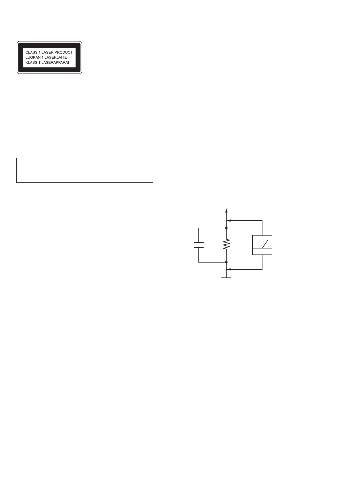
Leakage current can be measured by any one of three methods.
1. A commercial leakage tester, such as the Simpson 229 or RCA
WT-540A. Follow the manufacturers’ instructions to use these
instruments.
2. A battery-operated AC milliammeter. The Data Precision 245
digital multimeter is suitable for this job.
3. Measuring the voltage drop across a resistor by means of a
VOM or battery-operated AC voltmeter. The “limit” indication
is 0.75 V, so analog meters must have an accurate low-voltage
scale. The Simpson 250 and Sanwa SH-63Trd are examples
of a passive VOM that is suitable. Nearly all battery operated
digital multimeters that have a 2 V AC range are suitable. (See
Fig. A)
To Exposed Metal
Parts on Set
AC
1.5 kΩ0.15 μF
Earth Ground
voltmeter
(0.75 V)
Fig. A. Using an AC voltmeter to check AC leakage.
SAFETY-RELATED COMPONENT WARNING!
COMPONENTS IDENTIFIED BY MARK 0 OR DOTTED LINE
WITH MARK 0 ON THE SCHEMATIC DIAGRAMS AND IN
THE PARTS LIST ARE CRITICAL TO SAFE OPERATION.
REPLACE THESE COMPONENTS WITH SONY PARTS
WHOSE PART NUMBERS APPEAR AS SHOWN IN THIS
MANUAL OR IN SUPPLEMENTS PUBLISHED BY SONY.
2

TABLE OF CONTENTS
HBD-E770W
1. SERVICING NOTES ............................................. 4
2. DISASSEMBLY
2-1. Disassembly Flow ........................................................... 11
2-2. Case (EZ) ........................................................................ 11
2-3. MB-134 Board ................................................................ 12
2-4. Bracket (MB) Block ........................................................ 13
2-5. Fuse (F901), POWER Board .......................................... 13
2-6. Front Panel Block ........................................................... 14
2-7. BD Drive (BPX-5) .......................................................... 14
2-8. INCLUDE Board ............................................................ 15
2-9. Back Panel Block ............................................................ 15
2-10. MAIN Board ................................................................... 16
2-11. AUDIO Board ................................................................. 16
2-12. Optical Device (KEM-460AAA), Wire (Flat Type) ....... 17
3. TEST MODE ............................................................ 18
4. ELECTRICAL CHECK ......................................... 27
5. DIAGRAMS
5-1. Block Diagram - SERVO Section - ................................ 28
5-2. Block Diagram - MEMORY Section - ............................ 29
5-3. Block Diagram - TUNER, S-AIR Section - .................... 30
5-4. Block Diagram - AUDIO Section - ................................. 31
5-5. Block Diagram - REGULATOR Section - ...................... 32
5-6. Block Diagram
- PANEL, POWER SUPPLY Section - ........................... 33
5-7. Schematic Diagram - MB-134 Board (1/13) - ................ 35
5-8. Schematic Diagram - MB-134 Board (2/13) - ................ 36
5-9. Schematic Diagram - MB-134 Board (3/13) - ................ 37
5-10. Schematic Diagram - MB-134 Board (4/13) - ................ 38
5-11. Schematic Diagram - MB-134 Board (5/13) - ................ 39
5-12. Schematic Diagram - MB-134 Board (6/13) - ................ 40
5-13. Schematic Diagram - MB-134 Board (7/13) - ................ 41
5-14. Schematic Diagram - MB-134 Board (8/13) - ................ 42
5-15. Schematic Diagram - MB-134 Board (9/13) - ................ 43
5-16. Schematic Diagram - MB-134 Board (10/13) - .............. 44
5-17. Schematic Diagram - MB-134 Board (11/13) - .............. 45
5-18. Schematic Diagram - MB-134 Board (12/13) - .............. 46
5-19. Schematic Diagram - MB-134 Board (13/13) - .............. 47
5-20. Printed Wiring Board
- MB-134 Board (Component Side) - ............................. 48
5-21. Printed Wiring Board
- MB-134 Board (Conductor Side) - ............................... 49
5-22. Printed Wiring Board - AUDIO Board - ......................... 50
5-23. Schematic Diagram - AUDIO Board - ............................ 51
5-24. Printed Wiring Board
- MAIN Board (Component Side) - ................................ 52
5-25. Printed Wiring Board
- MAIN Board (Conductor Side) - .................................. 53
5-26. Schematic Diagram - MAIN Board (1/5) - ..................... 54
5-27. Schematic Diagram - MAIN Board (2/5) - ..................... 55
5-28. Schematic Diagram - MAIN Board (3/5) - ..................... 56
5-29. Schematic Diagram - MAIN Board (4/5) - ..................... 57
5-30. Schematic Diagram - MAIN Board (5/5) - ..................... 58
5-31. Printed Wiring Boards - KEY Section - .......................... 59
5-32. Schematic Diagram - KEY Section - .............................. 59
5-33. Printed Wiring Board - REG Board - .............................. 60
5-34. Schematic Diagram - REG Board - ................................ 61
5-35. Printed Wiring Board - INCLUDE Board - .................... 62
5-36. Schematic Diagram - INCLUDE Board - ....................... 63
5-37. Printed Wiring Board - FL Board - ................................. 64
5-38. Schematic Diagram - FL Board - .................................... 65
5-39. Printed Wiring Board - POWER Board - ........................ 66
5-40. Schematic Diagram - POWER Board - .......................... 67
6. EXPLODED VIEWS
6-1. Case, Front Panel Section ............................................... 92
6-2. MB-134 Board Section ................................................... 93
6-3. Back Panel Section ......................................................... 94
6-4. MAIN Board Section ...................................................... 95
6-5. BD Drive Section (BPX-5) ............................................. 96
7. ELECTRICAL PARTS LIST .............................. 97
3

HBD-E770W
SECTION 1
SERVICING NOTES
NOTES ON HANDLING THE OPTICAL PICK-UP
BLOCK OR BASE UNIT
The laser diode in the optical pick-up block may suffer electrostatic break-down because of the potential difference generated by
the charged electrostatic load, etc. on clothing and the human body.
During repair, pay attention to electrostatic break-down and also
use the procedure in the printed matter which is included in the
repair parts.
The fl exible board is easily damaged and should be handled with
care.
NOTES ON LASER DIODE EMISSION CHECK
The laser beam on this model is concentrated so as to be focused
on the disc refl ective surface by the objective lens in the optical
pickup block. Therefore, when checking the laser diode emission,
observe from more than 30 cm away from the objective lens.
UNLEADED SOLDER
Boards requiring use of unleaded solder are printed with the leadfree mark (LF) indicating the solder contains no lead.
(Caution: Some printed circuit boards may not come printed with
the lead free mark due to their particular size)
: LEAD FREE MARK
Unleaded solder has the following characteristics.
• Unleaded solder melts at a temperature about 40 °C higher
than ordinary solder.
Ordinary soldering irons can be used but the iron tip has to be
applied to the solder joint for a slightly longer time.
Soldering irons using a temperature regulator should be set to
about 350 °C.
Caution: The printed pattern (copper foil) may peel away if
the heated tip is applied for too long, so be careful!
• Strong viscosity
Unleaded solder is more viscous (sticky, less prone to fl ow)
than ordinary solder so use caution not to let solder bridges
occur such as on IC pins, etc.
• Usable with ordinary solder
It is best to use only unleaded solder but unleaded solder may
also be added to ordinary solder.
RELEASING THE DISC TRAY LOCK
The disc tray lock function for the antitheft of an demonstration
disc in the store is equipped.
Releasing Procedure:
1. Press the [
2. Press the [FUNCTION] button to select “BD/DVD”.
3. Press the [x] and [Z] buttons simultaneously and hold down
unit “DEMO OFF” displayed on the fluorescent indicator tube
(around 5 seconds).
Note: When “DEMO ON” is displayed, the disc tray lock is not released
by turning power on/off with the [
ABOUT THE LENS CLEANING
Do not do the lens cleaning with the cotton bud etc. It causes the
trouble.
] button to turn on the system.
?/1
?/1
] button.
NOTE THE IC101, IC104, IC105, IC204, IC205, IC307,
IC311, IC501 AND IC502 ON THE MB-134 BOARD
REPLACING
IC101, IC104, IC105, IC204, IC205, IC307, IC311, IC501 and
IC502 on the MB-134 board cannot exchange with single. When
these parts are damaged, exchange the entire mounted board.
TEST DISC
Part No. Description Layer
J-6090-199-A BLX-104 Single Layer
J-6090-200-A BLX-204 Dual Layer
J-2501-307-A CD (HLX-A1)
J-2501-305-A HLX-513 Single Layer (NTSC)
J-2501-306-A HLX-514 Dual Layer (NTSC)
J-6090-077-A HLX-506 Single Layer (PAL)
J-6090-078-A HLX-507 Dual Layer (PAL)
Note: Refer to the service manual of BDP-BX1/S350 (Part No. 9-883-
989-1[]) (page 1-3 to 1-14E) for the use of BLX-104/204.
Operation and Display:
1. BLX-104
Procedure:
1. Select 23.976Hz/1080p.
2. Play “4.Motion picture”.
3. Check whether player can play back or not.
4. Check each outputs.
Video:
Composite/S Video/component/HDMI.
Audio:
Speaker out.
* When 1080/24p monitor is nothing, 1080i (59.94Hz or 50Hz)
can use instead of 1080/24p.
However this is temporary correspondence.
2. BLX-204
Procedure:
1. Select 1080i (59.94Hz or 50Hz).
2. Play “4.Motion picture”.
3. Check whether player can play back or not (Check the picture
and sound output).
3. CD (HLX-A1)
Procedure:
Check whether player can play back or not (Check the sound output).
4. HLX-513/514 (NTSC), HLX-506/507 (PAL)
Procedure:
1. After displayed Main Menu, select “1.Video Signal”.
2. Play “1.Color bar 100%” (Check the picture and sound output).
3. Return to Menu.
4. Play “Demonstration 4:3” or “Demonstration 16:9” (Check the
picture and sound output).
4
HBD-E770W
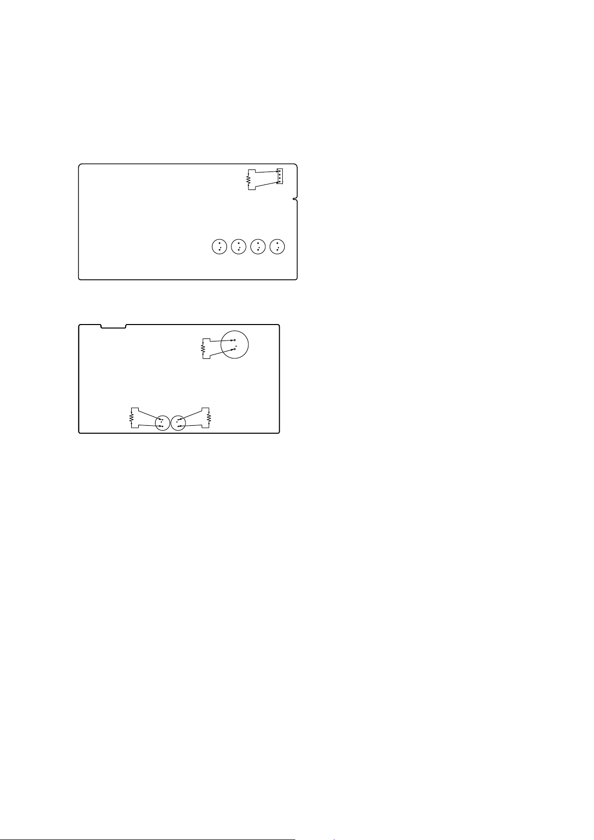
CAPACITOR ELECTRICAL DISCHARGE PROCESSING
When checking the board, the electrical discharge is necessary for
the electric shock prevention.
Connect the resistors referring to the fi gure below.
• MAIN board (C3115, C3125, C3215, C3315)
Both ends of CN3001.
– MAIN Board (Conductor Side) –
800 :/2 W
C3215
C3315
C3125
4
1
CN3001
C3115
• POWER board (C903, C932, C933)
Both ends of respective capacitors.
– POWER Board (Conductor Side) –
800 :/2 W
C903
C933
800 :/2 W
C932
800 :/2 W
1. Preparation
1-1. ESD Countermeasure
It is necessary to confi rm the state of static electricity in the work
space before the repair is started.
The static electricity resistance of the BD laser is weaker than that
of the DVD/CD laser.
Do work space and worker’s ESD countermeasures to prevent destruction by ESD.
1-2. Jig
• Digital camera (Recommend with macro mode)
• USB memory
• PC
• Barcode decoder (Refer to “1-3. Barcode decoder
(BDBUDEC)”)
1-3. Barcode decoder (BDBUDEC)
Part No. : J-6090-212-A
Jig name : BDBUDec.exe
Release : 2009.02.19
Version : 1.0.0.0
Software contents :
• BDBUDec.exe : Barcode decoder software
• SavePath.ini : Decoded fi le destination setting fi le (Ini-
tial destination is “C:\BuData.txt”)
• TasmanBars.dll : Decode dll
• Uninst.exe : Uninstall the “BDBUDec.exe” from PC
Install procedure:
1. Unzip the barcode decoder fi les to any PC folder.
2. Check the taken barcode photo click & drop onto “BDBUDec.
exe”.
When the barcode decoder is used for the fi rst time, the pass-
word is necessary. It is unnecessary since the second times.
NOTE OF REPLACING THE OPTICAL DEVICE (KEM460AAA) OR MB-134 BOARD
Optical device (KEM-460AAA) for BD requires precise read out
functions and secure contents protection system for more than past
DVD/CD.
Therefore, in the case repaired as follows, the writing work of the
OP data is necessary.
• When the optical device (KEM-460AAA) is replaced (The
MB-134 board doesn’t replace).
• When both the optical device (KEM-460AAA) and MB-134
board are replaced.
• When the MB-134 board is replaced (The optical device
(KEM-460AAA) doesn’t replace) (In this case, do the work of
“3. Optical device (KEM-460AAA) replacement” other than
the replacement of new optical device).
Note: The servo adjustment is done while writing the OP data. The manual
adjustment is unnecessary.
LD ON TIME history doesn’t carry over.
Do not touch any optical block parts, turn table and during replac-
ing. BD laser diode is very sensitive.
Note 1: The password will be supplied to only service headquarters, and
service center name/q’ty/all of software registered information
should be maintained by service headquarters.
Note 2: Do not change the decoded fi le name “BuData.txt”.
3. When “.NET frame work requirements” is displayed, download following applications from Microsoft download site.
• Microsoft .NET Framework Version 2.0 Redistributable Package (x86)
http://www.microsoft.com/downloads/details.aspx?displaylan
g=en&FamilyID=0856eacb-4362-4b0d-8edd-aab15c5e04f5
• Microsoft .NET Framework 2.0 Service Pack 1 (x86)
http://www.microsoft.com/downloads/details.aspx?displaylan
g=en&FamilyID=79bc3b77-e02c-4ad3-aacf-a7633f706ba5
5

HBD-E770W
2. Pass-fail judgment of the optical device (KEM-460AAA)
Perform pass-fail judgment to judge whether the repair of the optical device (KEM-460AAA) is necessary.
2-1. Flow of drive section check
Confirm whether
BD (BLX-104) can be
reproduced
YES
Confirm whether
DVD (HLX-513)/
CD (HLX-A1) can be
reproduced
Note: Refer to “2-12. OPTICAL DEVICE (KEM-460AAA), WIRE (FLAT TYPE)” (page 17) about how to remove the FFC HOLDER (REAR).
NO
NO
Confirm whether the
drive voltage is the
following values
CN301 pin 2 : 12 V
CN301 pin 6 : 5 V
YES
Confirm OP FFC cable
(Part No. 1-837-494-11)
and SPDL FFC cable
(Part No. 1-837-495-11),
and replace it when it
has been damaged
Then, confirm whether
this set operates
normally
YES
OK
NO
NO NO
Confirm PS301 to
PS304 on the MB-134
board, and replace it
when it has been
damaged
Confirm whether the
optical device IOP
is normal in the
service mode
(Refer to “2-2. Flow
of optical device
IOP check”)
Repalece the
optical device
(KEM-460AAA)
(Refer to “3. Optical
device (KEM-460AAA)
replacement”)
2-2. Flow of optical device IOP check
Turn the power on,
and change function
to “BD/DVD”
Press the buttons on
the remote commander
in order of [RETURN],
[0], [2], [1] [SUBTITLE],
and enter the service
mode
Confirm whether
value is the
specification value
Specification value:
BD : 6 mA
DVD/CD: 9 mA
YES
OK
NO
Repalece the
optical device
(Refer to “3. Optical
device (KEM-460AA)
replacement”)
Press the buttons on
the remote commander
in order of [8], [7], [3],
[ENTER], and the
dIOP value is displayed
6

3. Optical device (KEM-460AAA) replacement
Flow of replacement:
Note: The photo in fl ow is an image.
Barcode label on
new optical device
(KEM-460AAA)
bottom side
Take photo (JPEG)
by digital camera
Change photo into
the text data with
the barcode decoder
HBD-E770W
Save the text data
to USB memory
(memory capacity
need not be 8GB)
Connect USB memory
with rear USB connector
on this set, and read the
text data by the service mode
Procedure:
1. Remove the INSULATOR (4 pieces) and broken optical device (KEM-460AAA) from LOADING ASSY.
2. Take photo of the barcode on new optical device (KEM460AAA) bottom side by digital camera.
3. Assemble the INSULATOR (4 pieces) to new optical device
(KEM-460AAA), fi x (Torque value: 2 kgf) it to LOADING
ASSY with screw, and assemble this set.
4. Drag & drop the taken photo by step 2 to “BDBUDec.exe”,
and make the text data (File name: BuData.txt).
5. Save the text data to USB memory.
6. Connect USB memory with rear USB connector on this set,
and turn the power on.
7. Press the [FUNCTION] button to select “BD/DVD”.
8. Press the buttons on the remote commander in order of
[RETURN], [0], [2], [1], [SUBTITLE], and enter the service
mode.
9. Press the buttons on the remote commander in order of [8], [1],
[ENTER], and execute “[1] Drive OP data Write”.
10. Turn the power off after writing the OP data.
11. Turn the power on, and enter the service mode again.
12. Press the buttons on the remote commander in order of [8], [7],
[3], [ENTER], and the dIOP value is displayed.
13. Confi rm value is the following specifi cation value, and turn the
power off.
Specifi cation value:
BD : 6 mA
DVD/CD : 9 mA
14. Turn the power on, confi rm playback performance of the BD
(BLX-104)/DVD (HLX-513)/CD (HLX-A1).
15. Completely assemble this set, and complete the repair.
Rear USB connector
7
HBD-E770W
NOTE THE BD DRIVE (BPX-5) PARTS REPLACING
The mechanism blocks except optical device of BD drive (BPX-5)
are chiefl y composed of the following parts.
• CHUCK HOLDER ASSY
• LOADING ASSY
• HOLDER, FFC (REAR)
These parts are produced by two venders, it is not compatible.
Therefore, CHUCK HOLDER ASSY and LOADING ASSY are
supplied by one pair as repair parts. Please exchange both CHUCK
HOLDER ASSY and LOADING ASSY at the same time.
HOLDER FFC (REAR) need not be exchanged at the same time.
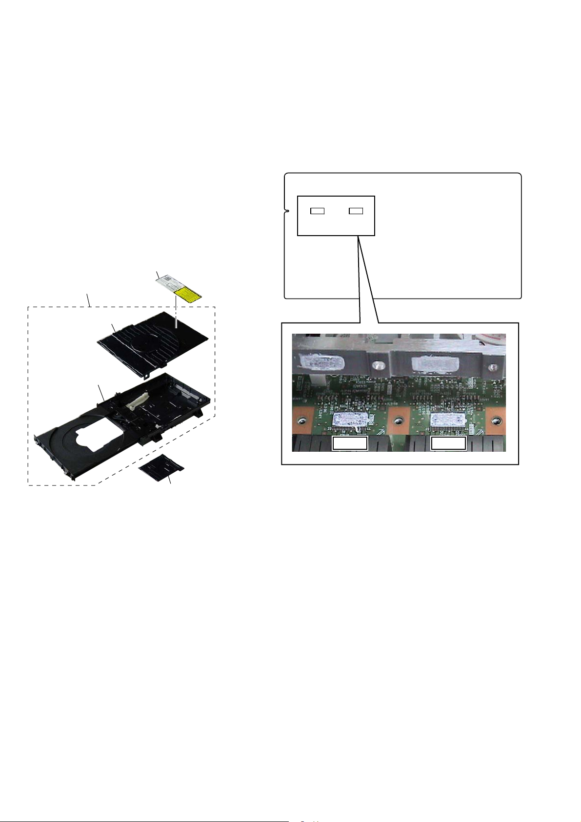
Note: The laser caution label is not pasted to LOADING FOR SERVICE
(Part No. A-1750-926-A). Please peel off an original laser caution
label, and paste it to LOADING FOR SERVICE when you use
LOADING FOR SERVICE.
LASER CAUTION LABEL
LOADING FOR SERVICE
CHUCK HOLDER ASSY
NOTE OF REPLACING THE THE IC3100 AND IC3200
ON THE MAIN BOARD AND THE COMPLETE MAIN
BOARD
When IC3100 and IC3200 on the MAIN board and the complete
MAIN board are replaced, it is necessary to spread the compound
(THERMAL COMPOUND (G747)) (Part No. J-2501-221-A ) between parts and heat sink.
Spread the compound referring to the fi gure below.
– MAIN Board (Component Side) –
IC3200IC3100
LOADING ASSY
IC3100 IC3200
HOLDER, FFC (REAR)
8
HBD-E770W
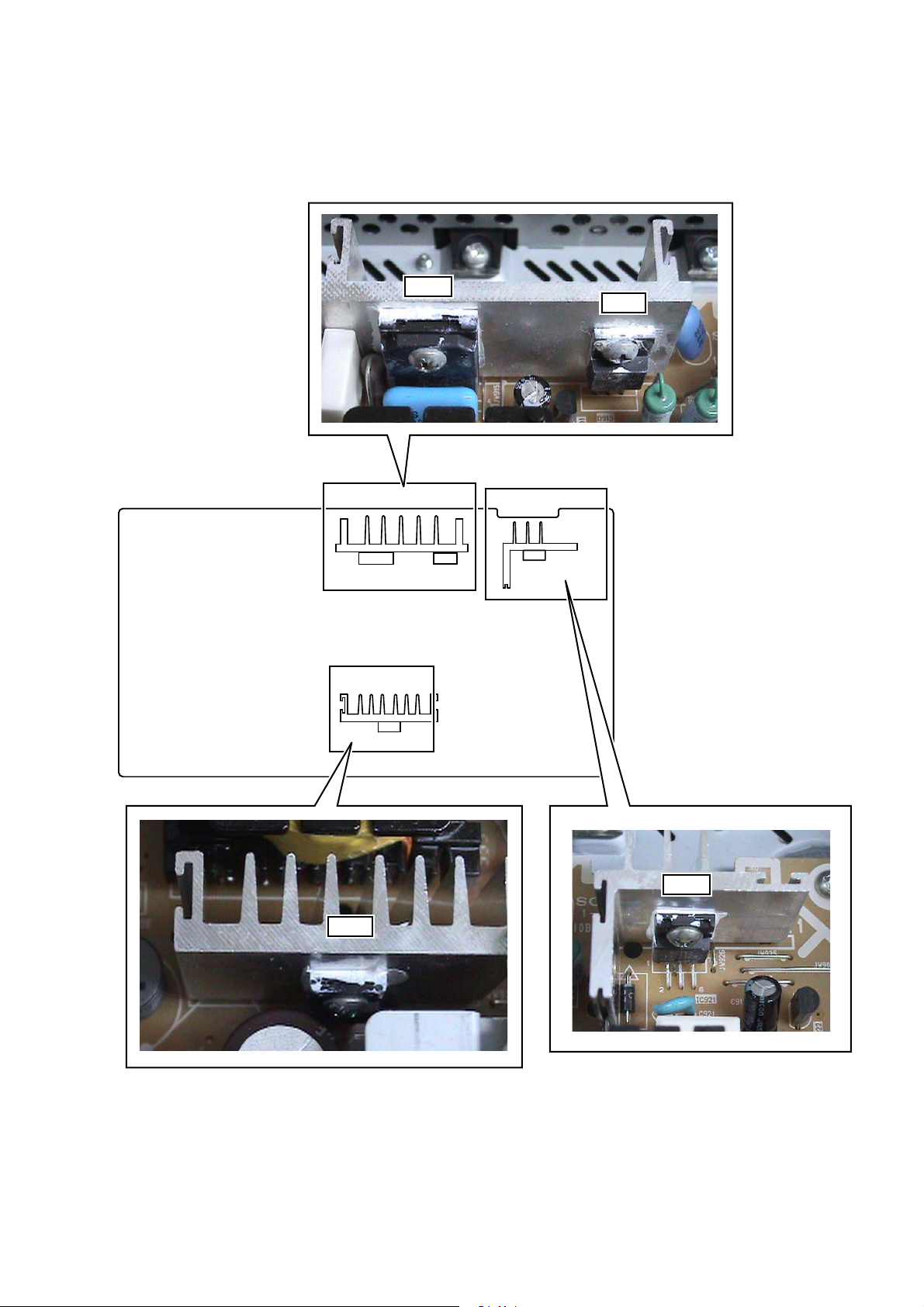
NOTE OF REPLACING THE D913, D931, IC901 AND IC921 ON THE POWER BOARD AND THE COMPLETE
POWER BOARD
When D913, D931, IC901 and IC921 on the POWER board and the complete POWER board are replaced, it is necessary to spread the
compound (THERMAL COMPOUND (G747)) (Part No. J-2501-221-A) between parts and heat sink.
Spread the compound referring to the fi gure below.
IC901
D913
– POWER Board
(Component Side) –
HS901
D931
IC901
HS931
D931
D913
HS921
IC921
IC921
9

HBD-E770W
HOW TO OPEN THE TRAY WHEN POWER SWITCH TURN OFF
Note 1: After the case is removed, this work is done.
Note 2: Please prepare the thin wire (clip etc.).
1 Remove the case.
(Illustration of disassembly is omitted.)
2
clip etc.
PROCESSING OF HARNESS (USB)
tray
3
– Top view –
10
DISASSEMBLY
• This set can be disassembled in the order shown below.
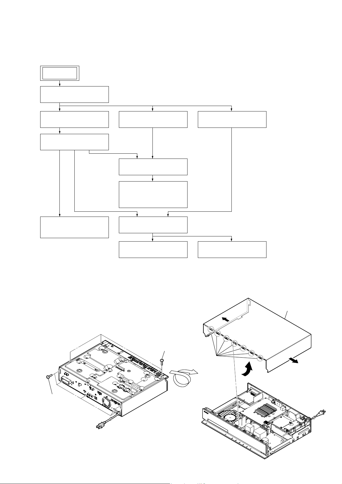
2-1. DISASSEMBLY FLOW
SET
2-2. CASE (EZ)
(Page 11)
HBD-E770W
SECTION 2
2-3. MB-134 BOARD
(Page 12)
2-4. BRACKET (MB) BLOCK
(Page 13)
2-5. FUSE (F901),
POWER BOARD
(Page 13)
Note: Follow the disassembly procedure in the numerical order given.
2-6. FRONT PANEL BLOCK
(Page 14)
2-7. BD DRIVE (BPX-5)
(Page 14)
2-12. OPTICAL DEVICE
(KEM-460AAA),
WIRE (FLAT TYPE)
(Page 17)
2-9. BACK PANEL BLOCK
(Page 15)
2-10. MAIN BOARD
(Page 16)
2-8. INCLUDE BOARD
(Page 15)
2-11. AUDIO BOARD
(Page 16)
2-2. CASE (EZ)
2 five screws
(BV/RING)
– Bottom view –
1 four screws
(BV3)
5 seven hooks
6 case (EZ)
3
3
4
11

HBD-E770W
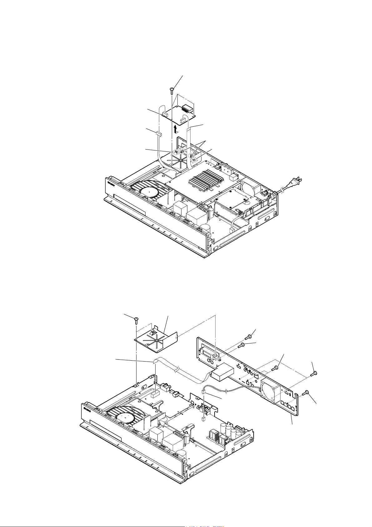
2-3. MB-134 BOARD
9 screw (BV3)
6 wire (flat type) (45 core)
(CN1401)
7 wire (flat type) (9 core)
(CN2460)
8 wire (flat type) (5 core)
(CN2470)
2 two connectors
(CN601, CN602)
q; clamp
9 four screws (BV3)
qd MB-134 board
4 wire (flat type) (18 core)
(CN902)
5 wire (flat type) (16 core)
(CN901)
qa screw (B3 u 5)
qs two screws (BV3)
1 connector (CN303)
3 wire (flat type) (27 core)
(CN1505)
12

2-4. BRACKET (MB) BLOCK
HBD-E770W
8 three screws (BV3)
5 connector (CN400)
1 power cord connector
(CN901)
7 screw
(BV3)
4 connector (CN403)
3 power-supply cord
8 two screws (BV3)
9 bracket (MB) block
2 cord bush (2104)
6 screw (P3 u 6)
2-5. FUSE (F901), POWER BOARD
9 POWER board
4 bracket R (MB foot)
6 connector
(CN17)
7 eight screws
(BV3)
1 glass fuse (DIA. 5) (8A/125V)
(F901)
2 screw (BV3)
5 connector
(CN904)
3
8 Remove the POWER board from
PC board holder.
13

HBD-E770W
2-6. FRONT PANEL BLOCK
Note: Please prepare the thin wire (clip etc.).
2
5 three screws
(BV3)
6 three ground plates (front)
7 three screws
(BV3)
q; connector
(CN700)
9
8 three claws
qa front panel block
8 two claws
1
clip etc.
2-7. BD DRIVE (BPX-5)
7 BD drive (BPX-5)
6 sound sheet
5
8 three claws
4 four screws (BV3)
1 screw (BV3)
3 bracket L (MB foot)
2
3 claw
7 three screws
(BV3)
3 three claws
4 loading panel assy
(10EZ)
14
2-8. INCLUDE BOARD
5 INCLUDE board
HBD-E770W
3 three screws
(BV3)
1 connector (CN204)
2-9. BACK PANEL BLOCK
guide rib
4
2 wire (flat type) (15 core)
(CN200)
two claws
guide rib
2 two screws
(BV3)
4 wire (flat type) (9 core)
(CN10)
3 bracket (S-AIR TAKE)
7 screw (BV3)
5 fan connector
(CN3000)
1 screw (BV3)
7 two screws (BV3)
6 two screws (BV3)
7 screw (BV3)
8 back panel block
15

HBD-E770W
2-10. MAIN BOARD
9 wire (flat type) (18 core)
(CN701)
7 wire (flat type) (17 core)
(CN503)
qd seven screws
(BV3)
8 wire (flat type) (15 core)
(CN702)
q; wire (flat type) (16 core)
(CN703)
qa three screws
(BV3)
qs heat sink
(S-master DDV)
5 wire (flat type) (27 core)
(CN505)
2-11. AUDIO BOARD
6 wire (flat type) (15 core)
(CN508)
1 screw
(BV3)
2
qd two screws
(BV3)
qf MAIN board
4 connector
(CN904)
3 bracket R
(MB foot)
6 three screws (BV3)
1 screw (BV3)
3 bracket L
(MB foot)
7 AUDIO board
2
4 connector
(CN17)
5 wire (flat type) (17 core)
(CN14)
16

2-12. OPTICAL DEVICE (KEM-460AAA), WIRE (FLAT TYPE)
Note: Please prepare the thin wire (clip etc.).
4 chuck holder assy (D)
1 two screws
(BVTP 2.6)
2 two claws
7 two float screws (S)
qa insulator
5 Insert the thin
wire (clip etc.).
8
0
3 two claws
qa insulator
qs optical device
(KEM-460AAA)
qa insulator
9
qd non-halogene tape
qf wire (flat type) (5 core)
HBD-E770W
qh ffc holder (rear)
qk wire (flat type)
(45 core)
qg
qj wire (flat type)
(9 core)
qa insulator
6
,QVWDOODWLRQRIZLUHIODWW\SHFRUHDQGZLUHIODWW\SHFRUH
This illustration sees the loading assy (D) from bottom side.
Note:
3 wire (flat type) (9 core)
4 Through the hole.
terminal face
Under the guide.
loading assy (D)
1 wire (flat type) (45 core)
Fold
2 Through the hole.
terminal face
boss
loading assy (D)
– Bottom view –
7 two claws
5 ffc holder (rear)
7 three claws
6
Under the guide.
(Fold area)
boss
17

HBD-E770W
SECTION 3
TEST MODE
COLD RESET
The cold reset clears data except BD/DVD data stored in the RAM
to initial conditions. Execute this mode when returning the set to
the customers.
Procedure:
1. Press the [
2. Press the [x] and [VOLUME –] buttons simultaneously and
hold down (around 5 seconds).
3. The message “COLD RESET” appears on fl uorescent indica-
tor tube, then becomes standby states.
DEMO MODE
This mode let you lock the disc tray. When this mode is activated,
the disc will not eject when the [
“LOCKED” will be displayed on the fluorescent indicator tube.
Procedure:
1. Press the [
2. Press the [FUNCTION] button to select the “BD/DVD”.
3. Press the [
until “DEMO ON” or “DEMO OFF” displayed on the fluorescent indicator tube (around 5 seconds).
S-AIR ID SETTING DISPLAY
Procedure:
1. Press the [
2. Press the [FUNCTION] and [VOLUME +] buttons simultaneously and hold down (around 5 seconds).
3. S-AIR ID setting is displayed on the fl uorescent indicator tube.
] button to turn the power on.
?/1
] button is pressed. The message
Z
] button to turn the power on.
?/1
] and [Z] buttons simultaneously and hold down
x
] button to turn the power on.
?/1
AMP TEST
Procedure:
1. Press the [
2. Press button in order of the [RETURN] → [0] → [1] → [1]
→ [SUBTITLE] on the remote commander (Make the interval
when each button is pressed within two seconds).
3. The message “MEASURE” appears on the fluorescent indicator tube and enter the AMP test mode.
4. Press the [BLUE] button on the remote commander, the state
of D.C.A.C. microphone is displayed on the fl uorescent indica-
tor tube.
*** @@ $$$
*** : Either of “IN”/“NON” is displayed by the state of
@@ : Either of “OK”/“NG” is displayed by the state of
$$$ : Microphone input audio data A/D value (0 – 255).
5. Press the [MUTING] button on the remote commander, “VOL
N” (The change in the volume is usual)/“VOL MSM” (The
change in the volume is a switch of MIN/1/20/MAX) can be
switched.
6. Press the [SUBTITLE] button on the remote commander, the
message “VACS ON” or “VACS OFF” appears on the fl uores-
cent indicator tube and thus the VACS on/off are changed.
7. To release from this mode, press the [
] button to turn the power on.
?/1
detection of the microphone.
digital audio data input.
?/1
] button.
PANEL TEST
Procedure:
1. Press the [
2. Press button in order of the [RETURN] → [0] → [0] → [1]
→ [SUBTITLE] on the remote commander (Make the interval
when each button is pressed within two seconds).
3. All segments in fl uorescent indicator tube are lighted up. And
half segments in fl uorescent indicator tube are lighted up, oth-
ers half segments in fl uorescent indicator tube are lighted up,
then LEDs and all segments in fl uorescent indicator tube are
lighted up. This operation is repeated.
4. When all segments in fl uorescent indicator tube are lighted up
in the state of step 3, press the [VOLUME +] button on the
remote commander and model information is displayed on the
fl uorescent indicator tube.
Each time the [VOLUME +] button on the remote commander
is pressed, the display changes from destination information,
STR version, SYS version, UI version, BDLIB version, ST
version, TA version, DSP version, TM version, CEC version,
SAIR version, PF version in this order, and returns to the model information display.
Each time the [VOLUME –] button on the remote commander
is pressed, the version and date are switched.
5. In the state of step 3, press the [FUNCTION] button on the
remote commander and “K 0” is displayed on the fluorescent
indicator tube.
“K 0” value increases whenever a button on the set is pressed.
However, once a button has been pressed, it is no longed taken
into account.
All buttons on the set are pressed, “OK” and “K 7” are alter-
nately displayed on the fluorescent indicator tube.
6. To release from this mode, press the [
] button to turn the power on.
?/1
?/1
] button.
BD SERVICE MODE
Note: The operation in this mode must use a remote commander.
Setting method of the BD service mode:
1. Press the [
2. Press button in order of the [RETURN] → [0] → [2] → [1] →
[SUBTITLE] on the remote commander. (Make the interval
when each button is pressed within two seconds)
3. Enter the BD service mode.
1. Main Functions
• ErrorLog display
Display the error log. Displayed contents can also be saved in
an USB memory device.
• Diag
Performs unit test of devices installed on the board.
• Factory Initialize
Restores the set to its factory settings.
• Network
Checks the wired network connection.
• Version Up (version update)
Not used.
• System Information
Displays the system information of the set.
Displays information such as the software version, drive infor-
mation, etc.
• EMC Test Mode
Not used.
• Drive
Write drive OP data and check drive.
] button to turn the power on.
?/1
18
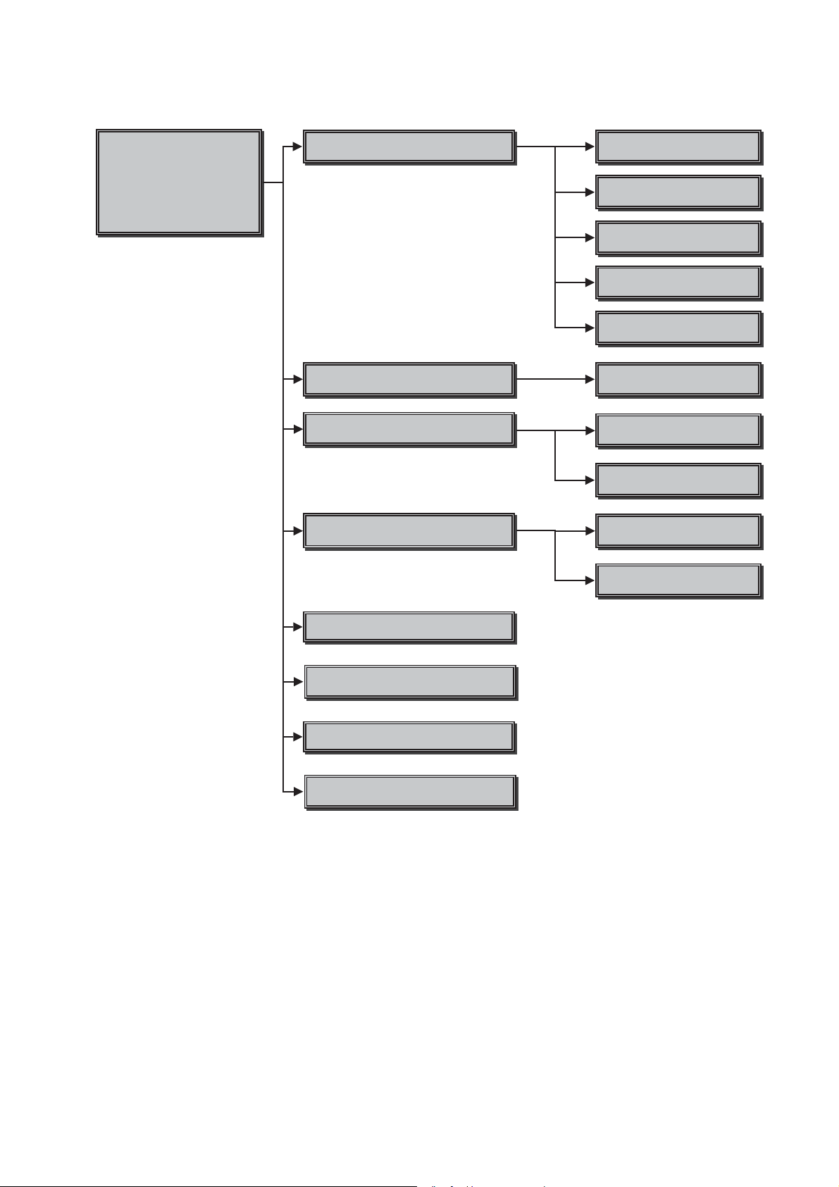
2. Menu Tree
HBD-E770W
Service Mode Menu
Service Mode Menu
[1] Diag
[1] Diag
[2] Log
[2] Log
[3] Factory Initialize
[3] Factory Initialize
[4] Network
[4] Network
[5] Version Up
[5] Version Up
[6] System Information
[6] System Information
[7] EMC Test Mode
[8] Drive
Diag
Diag Test
Log
Displays Error Log
Factory Initialize
5estores set to factory settings
Network
Network diagnosis for wired
Device Test
US%D$CIFcon test
Video Test
Video output test
$udio Test
$udio output test
$udio Input Test
$udio Input Test
:ireless L$N Test
Not used
Error Log
Displays error log
Start Initialize
Initialize default setting for %Dplayer
Start Initialize for TV
Not used
Ifconfig
View network status
Version Up
Not used
System Information
Displays system information
EMC Test Mode
Not used
Drive
Write drive OP data and check drive
Ping
Confirm network connection
19
HBD-E770W
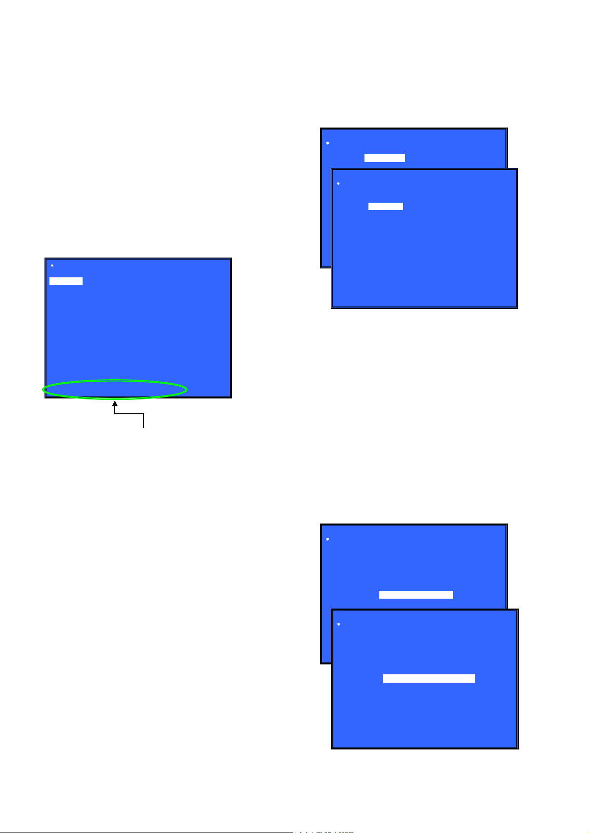
3. Service Mode Menu (Top Menu)
This is the top menu of service mode.
Each function is accessed from this screen.
Operation:
[1] Moves to Diag screen
[2] Moves to Log screen
[3] Moves to Factory Initialize screen
[4] Moves to Network screen
[5] Moves to Version Up (DISC version update) screen (Not
used)
[6] Moves to System Information screen
[7] Moves to EMC test mode screen (Not used)
[8] Moves to Drive screen
[
]/[m] Moves the cursor
M
3] Moves to the screen of the item selected with the cursor
[
* Cursor is not displayed when the menu is fi rst displayed.
Service Mode Menu
[1] Diag
[1] Diag
[2] Log
[3] Factory Initialize
[4] Network
[5] Version Up
[6] System Information
[7] EMC Test Mode
[8] Drive
• Device Test: List of devices
USB Host (*1)
*1) USB media check (front and rear). Only one time.
* For details concerning device test, see the Diag reference.
Diag
Device Test
Category: Device Test
USB Host
Device:
Rear USB Media check ... OK
Front USB Media check ... OK
Checking...
(Screen 1)
(Screen 2)
Category:
Diag
HELP: [RIGHT] [UP] [ENT] [RET]
5. Diag (Video/Audio Test)
This screen performs video and audio tests.
HELP : [DOWN] [ENT] [(NUM)]
HELP (currently available keys, etc.) is displayed
4. Diag (Device Test)
This screen is used to test devices mounted on the board.
Screen 1: Selects the test category
Operation:
[<]/[,] Selects the category
[m]/[3] Moves to the selected category
Screen 2: Device test
Selects the device to test after selecting Device Test in screen 1.
Operation:
[<]/[,] Selects the device to test
[3] Executes the test
[M] Returns to selection of test category
Selects the cursor during IFCon and D terminal tests
[m] Selects the cursor during IFCon and D terminal tests
• List of test categories
Device Test
Video Test
Audio Test
Audio Input Test
Wireless LAN Test (not used)
Screen 1: When video test category is selected
Operation:
[3] Shows/hides the color bar
[M]/[RETURN] Returns to the selection of test category
Screen 2: When audio test category is selected
Operation:
[3] Plays back/stops the tone sound
[M]/[RETURN] Returns to the selection of test category
• Video test:
Outputs a color bar (composite & component & HDMI).
• Audio test:
TONE sound output (speaker (8 ch) & HDMI (2 ch)).
Diag
Category: Video Test
[ENT] Show Color Bar
Diag
Category: Audio Test
(Screen 1)
HELP: [UP][ENT][RET]
[ENT] Generate TONE Sound
20
(Screen 2)
HELP: [UP] [ENT] [RET]

HBD-E770W
6. Diag (Audio Input Test)
This screen performs audio input test.
Screen 1: Selects the test category
Operation:
[<]/[,] Selects the category
[m]/[3] Moves to the selected category
Screen 2: Select Audio Input Test
Operation:
[M]/[m] Select test
[3] Start/stop input sound
[RETURN] Returns to the selection of test category
• Digital Input
Input : SPDIF (optical, 48 kHz, 2 ch only).
Sound output : Speaker (2 ch).
• Analog Input
Input : Line In (2 ch).
Sound output : Speaker (2 ch).
Diag
Category: Audio Input Test
Diag
Category: Audio Input Test
Device: Digital Input
Analog Input
[ENT] Start Input Sound
8. Log: Error Log (Output of each Log)
This screen displays the contents of each log.
Note: Do not refer to the displayed date.
Screen 1: Selects log
Operation:
[1]/[
3] Moves to the Error Log output screen
[RETURN] Returns to the top menu of the service mode
Screen 2: Displays the Error Log
Operation:
[<] Returns to the previous page
[,] Moves to the next page
[RETURN] Returns to the screen (screen 1) that selects the log
type
[RED] Writes the log contents to an USB memory device
• Viewing the log display
Error Log:
001 08/01/01 00: 53: 19: [ErrCode: 080400000000]
[Number (starting from old log) ] [date] [time] [error code]
About copying log to USB memory device:
Press the [RED] button in each log display screen with the USB
memory device inserted into the set
Note: Please do not press the [RED] button immediately after USB mem-
ory is inserted.
Please do not pull out USB memory immediately after the [RED]
button was pressed.
Error Log:
When “getErrLogFile.trm fi le” exists in the USB memory de-
vice, errlog.log fi le is output.
(Screen 1)
(Screen 2)
HELP: [UP][ENT][RET]
HELP: [UP] [ENT] [RET]
7. Diag (Wireless LAN Test)
This screen performs wireless LAN test.
Note: Not used for the servicing.
(Screen 1)
(Screen 2)
Select Log
[1] Error Log
Error Log
001 08/01/01 00: 53: 19: [ErrCode: 080400000000]
002 08/01/01 00: 53: 45: [ErrCode: 080400252100]
003 08/01/01 00: 54: 00: [ErrCode: 080400005555]
HELP : [DOWN][ENT][(NUM)]
:
:
21

HBD-E770W
9. Factory Initialize (Factory Settings)
Return all of the player setting to their factory defaults.
Operation:
Screen 1
Press the [1] button in this screen when restoring the set to its factory settings.
All saved titles will also be deleted.
[1] Start Factory Initialize
[2] Start Factory Initialize for TV (Not used)
[M]/[m] Moves the cursor
[3] Activate the selected cursor
[RETURN] Returns to the top menu of the service mode
Screen 2
It is a screen of the end of initialization.
[RETURN] Returns to the top menu of the service mode
To complete factory initialize, process COLD RESET subsequently.
Please disconnect AC power cord, and connect AC again. Then
press the [
] button to turn the power on, and press the [x] and
?/1
[VOLUME –] buttons simultaneously and hold down (around 5
seconds) to execute COLD RESET.
Remove the AC power cord and insert the AC power cord again.
* Operations in other service menus can also be performed.
Factory Initialize
[1] Start Initialize
[2] Start Initialize for TV
10. Network (Network Test Diagnosis Screen: Ifconfi g)
Network menu for the wired ethernet.
Screen 1: Ifconfi g Test
Operation:
[3] Activate Ifconfi g (Display network setting)
[,] Select ping test
[RETURN] Returns to the top menu of the service mode
Screen 2: Ping Test
Operation:
[<] Select Ifconfi g test
[RETURN] Returns to the top menu of the service mode
(The details of a Ping test are “11. Network (Network Test Diagnosis Screen: Ping)”)
Screen 3: Ifconfi g Test Active
Display Ifconfi g command results.
Operation:
[3] Ifconfi g retry
[,] Select Ping Test
[RETURN] Returns to the top menu of the service mode
Network
Test: Ifconfig Ping
Network
Test: Ifconfig Ping
Ping To:
[START]
(Screen 1)
(Screen 2)
[RET] Return to Top Menu
Factory Initialize
Reboot to complete.
[RET] Return to Top Menu
HELP: [RET]
(Screen 1)
(Screen 2)
Network
HELP : [DOWN][ENT][(NUM)]
(Screen 3)
Test: Ifconfig Ping
IP 192. 168. 11. 2 MAC 00-16-01-85-21-A3
HELP : [DOWN][ENT][(NUM)]
HELP : [ENT]: Re/Exe [RIGHT]
22

HBD-E770W
11. Network (Network Test Diagnosis Screen: Ping)
Ping test for the wired ethernet.
Screen 1: Ping Test
Operation:
[<] Select Ifconfi g test
[m] Ping execution preparation
[RETURN] Returns to the top menu of the service mode
Screen 2: The IP address of the Ping point is set up
(IP address input mode)
When “Ping to :>” is reversed, the [3] button is pressed and IP is
inputted.
Operation:
[3] Finish to input
[RETURN] Finish to input
[<] Finish to input and Select Ifconfi g Test
[0] to [9] Input Character sting ‘0-9’
[TIME] Input Character sting ‘.’
[CLEAR] Backspace
Screen 3: Ping Test Active
When [START] is reversed, the [
3] button is pressed and execute
ping.
Operation:
3] Activate ping test
[
[M] The IP address of the ping point is set up
[RETURN] Returns to the top menu of the service mode
Network
Ifconfig
(Screen 1)
(Screen 2)
Test:
(Screen 3)
Ping To :
Network
Test: Ifconfig
Ping
[START]
Ping to :> 192. 168. 200. 13
Network
Test: Ifconfig
PING 192. 168. 200. 13 OK!
HELP: [ENT] : Start [UP] [LEFT]
Ping
[ENT] : Release
[RET] : Release
Ping
Ping to : 192. 168. 200. 13
[START]
12. System Information (System Information Display)
This screen displays system information.
Screen 2: Drive Information Menu
Operation:
[
] Basic Information displayed (go to screen 1)
<
[RETURN] Returns to the top menu of the service mode
When delta IOP is measured, it becomes impossible to use the Version Up function.
Contents List:
Model
Destination
Sequence Number
MAC
IP
IFCON IFCON Version
Bootloader Bootloader Version
Host Main Host Main Version
Host Sub Host Sub Version
Middleware Middleware Version
ADSP ADSP Version
IF Model
IF Dest
Drive Firm Revision
CD DIOP Delta IOP
DVD DIOP Delta IOP
BD DIOP Delta IOP
CD LD TIME LD Time
DVD LD TIME LD Time
BD LD TIME LD Time
(Screen 1)
System Information
Model :
Destination :
Sequence Number :
MAC :
IP :
IF-con Block0 Version : Block1 Version :
Bootloader Version :
Host Main Version :
Host Sub Version :
Middleware Version :
ADSP Version :
IF_MODEL :
IF_DEST :
HELP: [RET] [RIGHT]
(Screen 2)
System Information
Drive Firm Revision :
CD DIOP :
DVD DIOP :
BD DIOP :
CD LD TIME :
DVD LD TIME :
BD LD TIME :
Screen 1: Basic Information
Operation:
] Drive information (delta IOP of a drive is measured)
[
,
displayed (go to screen 2)
[RETURN] Returns to the top menu of the service mode
HELP: [RET] [LEFT]
23

HBD-E770W
13. Drive
This menu is used to operate the drive using drive-related diagnostic and tools.
Screen 1: Selecting items under *Service Menu
(Screen 1)
Service Menu
[1] Diag
[2] Log
[3] Factory Initialize
[4] Network
[5] Version Up
[6] System Information
[7] EMC Test Mode
[8] Drive
Screen 2: Selecting items under *Drive
(Screen 2)
Drive
[1]Drive OP data Write
[2]Servo Parameter Check Menu
[3]Servo Signal Check Menu
[4]S -Curve Check Menu
[5]Readability Check Menu
[6]OP Position Check Menu
[7]OP Check Menu
[8]Load Eject Aging
[9]Spindle Control Check Menu
[10]FA Test Mode
Screen 3: *Drive OP data Write
Purpose: Write OP data into fl ash IC
[
]/[m] Move the cursor up and down
M
3] Start the selected cursor item
[
[RETURN] Returns to the top menu of the service mode
(Screen 3)
Drive OP data Write
Insert USB StorageDevice ...
Remove DISC and Close tray.
[1]Disc: Eject
[ENT] Start
Screen 4: *Servo Parameter Check Menu (Not Used)
(Screen 4)
Servo Parameter Check Menu
[1] Disc: Eject
[2] Show Parameters
Operation:
[M]/[m] Move the cursor up and down
[3] Open the selected cursor item
[RETURN] Returns to the top menu of the service mode
• Test item list
[1] Drive OP data Write
[2] Servo Parameter Check Menu
[3] Servo Signal Check Menu
[4] S-Curve Check Menu
[5] Readability Check Menu
[6] OP Position Check Menu
[7] OP Check Menu
[8] Load Eject Aging
[9] Spindle Control Check Menu
[10] FA Test Mode
Not used for the servicing.
Press the [RETURN] button if having entered this mode.
Screen 5: *Servo Signal Check Menu (Not Used)
(Screen 5)
Servo Signal Check Menu
[1] Disc: Eject
[2] Servo Signal Monitor out: OFF
[3] RTADJ: OFF
[4] FocusBias: 0000
[5] SA -Act.move: FWD 00 step
[6] Pl Level: 0000
[7] RF Level: 0000
[8] TRV Level: 0000
[9] Current FB: 0000 SA: 0000
Not used for the servicing.
Press the [RETURN] button if having entered this mode.
24

HBD-E770W
Screen 6: *S-Curve Check Menu (Not Used)
(Screen 6)
S - Curve Check Menu
[1] Disc: Eject
[2] Media Type: BD - ROM SL
[3] Layer: L0
[4] SLD move to Home
[5] SLD move: FWD 00 step
[6] FCS Search start
Not used for the servicing.
Press the [RETURN] button if having entered this mode.
Screen 7: *Readability Check Menu (Not Used)
(Screen 7)
Readability Check Menu
[1] Disc: Eject
[2] Address: 00000000
[3] Length: 0000
[4] Execute
Jitter P: 0000
Jitter PR: 0000
Jitter DC: 0000
SER: 0000 0000
Screen 9: *OP Check Menu
Purpose: Verify OP related such as delta IOP and LD time
[
]/[m] Move the cursor up and down
M
3] Start the selected cursor item
[
[RETURN] Returns to the top menu of the service mode
(Screen 9)
OP Check Menu
Remove DISC and Close tray
[1] Disc Eject
[2] OP Serial: xxxxxxxxxxxxxx
[3] dIOP
BD: x[xx]
DVD: x[xx]
CD: x[xx]
TEMP: xx.x deg
[4] LD ON Time
BD: xxxxh xxm
DVD: xxxxh xxm
CD: xxxxh xxm
Screen 10: *Load Eject Aging (Not Used)
(Screen 10)
Load Eject Aging
[1] Disc: Eject
[2] Repeat set: 00000
[3] Mecha type: Tray mecha
[4] Aging type: Normal
[5] Start
Not used for the servicing.
Press the [RETURN] button if having entered this mode.
Screen 8: *OP Position Check Menu (Not Used)
(Screen 8)
OP Position Check Menu
[1] Disc: Eject
[2] OP Position Check
Not used for the servicing.
Press the [RETURN] button if having entered this mode.
Not used for the servicing.
Press the [RETURN] button if having entered this mode.
Screen 11: *Spindle Control Check Menu (Not Used)
(Screen 11)
Spindle Control Check Menu
[1] Disc : Eject
[2] rpm: 0000 rpm
[3] Spindle: OFF
Not used for the servicing.
Press the [RETURN] button if having entered this mode.
25

HBD-E770W
Screen 12: *FA Mode Test (Not Used)
(Screen 12)
FA Mode Test
[1] Enter Repeat FA mode
Repeat number: 0000
[2] Save FE log to USB
Not used for the servicing.
Press the [RETURN] button if having entered this mode.
CONFIRMATION ITEM
1. Playback Operation Confi rmation
1-1. Test Disc
Part No. Description Layer
J-6090-199-A BLX-104 Single Layer
J-6090-200-A BLX-204 Dual Layer
J-2501-307-A CD (HLX-A1)
J-2501-305-A HLX-513 Single Layer (NTSC)
J-2501-306-A HLX-514 Dual Layer (NTSC)
J-6090-077-A HLX-506 Single Layer (PAL)
J-6090-078-A HLX-507 Dual Layer (PAL)
Note: Refer to the service manual of BDP-BX1/S350 (Part No. 9-883-
989-1[]) (page 1-3 to 1-14E) for the use of BLX-104/204.
Operation and Display:
1. BLX-104
Procedure:
1. Select 23.976Hz/1080p.
2. Play “4.Motion picture”.
3. Check whether player can play back or not.
4. Check each outputs.
Video:
Composite/S Video/component/HDMI.
Audio:
Speaker out.
* When 1080/24p monitor is nothing, 1080i (59.94Hz or 50Hz)
can use instead of 1080/24p.
However this is temporary correspondence.
* When the output of HDMI is 1080p, the signal of Composite/S
Video/Component are not output.
It is necessary to lower the output of HDMI to 1080i or less.
3. CD (HLX-A1)
Procedure:
Check whether player can play back or not.
(Check the sound output)
4. HLX-513/514 (NTSC), HLX-506/507 (PAL)
Procedure:
1. After displayed Main Menu, select “1.Video Signal”.
2. Play “1.Color bar 100%”.
(Check the picture and sound output)
3. Return to Menu.
4. Play “Demonstration 4:3” or “Demonstration 16:9”.
(Check the picture and sound output)
1-2. Playback operation confi rmation
Confi rm operation in each signal/output mode of test disc (BLX-
104/204) according to the content of the repair.
Note: “AV Sync.” doesn’t operate.
2. Networking Confi rmation
Confi rm it according to the following procedure when you confi rm
the connection of the network.
Note: Do not execute “Network Connection Diagnostics” of “Network
Settings” of the home menu with only the router connected.
Procedure:
1. Connect the router with the set with LAN cable.
2. Turn on the power of the set and the router.
3. Press the [HOME] button on the remote commander, and the
home menu is displayed.
4. Select “Setup” → “Network Settings” → “Internet Settings”,
and press the [3] button on the remote commander.
5. Select “View Networks Status” and press the [3] button on the
remote commander.
6. Confi rm IP address are displayed in “IP Address”, “Subnet
Mask” and “Default Gateway”.
Physical Connection: XXXX
Internet Access: XXXX
IP Address Setting: XXXX
IP Address: XXX.XXX.XXX.XXX
Subnet Mask: XXX.XXX.XXX.XXX
Default Gateway: XXX.XXX.XXX.XXX
DNS Settings: XXXX
Primary DNS: XXX.XXX.XXX.XXX
Secondary DNS: XXX.XXX.XXX.XXX
MAC Address: XXX.XXX.XXX.XXX
2. BLX-204
Procedure:
1. Select 1080i (59.94Hz or 50Hz).
2. Play “4.Motion picture”.
3. Check whether player can play back or not.
(Check the picture and sound output)
26

HBD-E770W
HBD-E770W
2727
SECTION 4
ELECTRICAL CHECK
FM TUNER LEVEL CHECK
Procedure:
1. Turn on the set.
2. Input the following signal from Signal Generator to FM antenna
input directly.
Carrier frequency : A = 87.5 MHz, B = 98 MHz, C = 108 MHz
Deviation : 75 kHz
Modulation : 1 kHz
ANT input : 35 dBu (EMF)
Note: Use 75 ohm coaxial cable to connect signal generator and the set.
You cannot use video cable for checking.
Use signal generator whose output impedance is 75 ohm.
3. Set to FM tuner function and tune A, B and C signals.
4. Confi rm “TUNED” is lit on the display for A, B and C signals.
When the selected station signal is received in good condition,
“TUNED” is displayed.
signal
generator
set

HBD-E770W
HBD-E770W
2828
SECTION 5
DIAGRAMS
5-1. BLOCK DIAGRAM - SERVO Section -
X1201
25MHz
6,*1$/3$7+
$8',2
9,'(2
',6&3/$<
86%
/$1
(7+(51(7,17(5)$&(
,&
7;' 23 (77;'
&
7;'
5;' 18
5;' 17
0',2
0'& 2
(77;'
'
(75;'
$
(75;'
%
6 7;128
5
2
1
7;3
29
5;1
31
5;3
32
;7$/13
&/.,1
(70',2
%
(70'&
)
7;&/.
22 (77;&/.
&
5;B&/.
20
Q567
5
(75;&/.
$
7;B(5
1 (77;(5
(
5;B(5 21
7;B(1 6
(75;(5
%
(77;(1
'
&2/
36 (7&2/
&
&56
3 (7&56
+
5;B'9
19 (75;'9
)
$
%
%''(&2'(5
,&
%''5,9(
%3;
)(B5),3<%'B5)
)(B5),1<
W1
W3
%'B5)
)(B,1$3%
)(B,1%1$
)(B,1&5'
)(B,1'7&
)(B,1(V6*
)(B,1)8H
)(B,1*5(
)(B,1+7)
)(B75$<,1
$-
75$<,1
)(B75$<287
$.
75$<287
)(B&)5(4
$'
6',2
)(B262(1
$(
6&/.
)(B&02'
$)
6(1B/''
)(B)3'2'9'77(67B9
)(B*,2-02'(B$
)(B*,2-02'(B%
)(B*,2*02'(B&
)(B*,2*/'(1
%
%
$
$
)(B+$9&-9&B3'
)(B$8;07+(502
)(B9'$&/6$B,1,7
)(B75$<3:0
$(
)(B752
$+
)(B)22
$'
)(B7/2
$0
)(B)02
$)
)(B)02
$(
)(B'02
$)
)(B/,0,7
$*
)(B*,2
$'
)(B*,2
$*
)(B*$,16:
$'
)(B)**
)(B5),3'9'B5)
)(B5),1'9'B5)
16B5),3.
16B5),1+
16B&.,1)
)(B03;287
.
)(B*,2
(
)(B03;287
/
86%B'3
$/
86%B'0
$.
&1
3
2
86%B'3
$0
86%B'0
$/
&1
3
2
&+B3
'
&+B0
%
&+B3
&
&+B0
$
&+B3
'
&+B0
%
&/.B3
&
&/.B0
$
+'0,6'
(
+'0,6&.
)
+73/*
&(&
$5&B63',)
'$7$B,
*
%8))(5
4
70'6'$7$
70'6'$7$±
70'6'$7$
70'6'$7$±
70'6'$7$
70'6'$7$±
70'6&/2&.
70'6&/2&.±
9,1'
*
9,1'
+
&(&
6&/
6'$
+3'
1
3
5(6(59('$5&
6
7
9
10
12
15
16
19
13
&1
+'0,
$5&287
:$9(
6+$3(5
,&
0&,1
)
,5
9,1'
%
(
9,1'
9,1'
$
*
63'$7$
*
630&/.
63%&.
&
$
63/5&.
63B'$7$
63B0&.
63B%&.
63B/5&.
%
9,1'
'
9,1'
$
9,1'
)
9,1'
',5B(5525
&6,B'$7$,1
',5B&6)/$*
',5B$8',2
&6,B'$7$287
&6,B&/.
&6,B;&6B',5
',5B;67$7(
(
$26'$7$
&
$26'$7$
*
$26'$7$
H22
$26'$7$
$26'$7$
$26'$7$
$26'$7$
)
$26'$7$
(
$20&/.
'
$26'$7$
$26'$7$
$20&.
$2%&.
%
$2/5&.
(
$2%&.
$2/5&.
6<6&21B567
9,1' ',5B;567
%
-
3%&%
35&5
<
&20321(17
9,'(2287
133URXW
103<RXW
113ERXW
9,'(2$03
,&
3<LQ
3ELQ
5
3ULQ
6'+'
3
0XWH
8
7
9LQ
1
'$&287
'$&287
%
'$&287
$
&
'$&287
'
159RXW
9,'(2287
5;' 16
5;' 15
(75;'
&
(75;'
$
7;' 26 (77;'
'
7;' 27
02725'5,9(5
,&
;)*
11
021,725 12
96/('
16
96/('
17
6/('B3
52
6/('B153
6/('B3
55
6/('B1
56
W
V
8
&20021
8
V
W
0&20
/2$'
/2$'
/2$'B332
/2$'B1
33
75
7'
75.B329
75.B1
30
)'
)5
)&6B327
)&6B1
28
)'
)5
7/7B3
7/7B1
25
963,1
18
9/2$'
19
*&
15
975.
6$B%
6$B%
6$B$
6$B$
)(B*$,16:
$(
)(B)02
$)
)(B)02
$*
02725'5,9(55(*8/$725
,&
673B,1
8
673B,1
9
673
16
67317
673
18
673
19
)(9
)(9
5(*39
5(*3[9
22
67(3B(1$
7
20
9)&6
21
97/7
22
;087(
13
;087(
(77;'
(
&1
(7+(51(7
&211(&725
/$1
(Page 31)
(Page 30)
HBD-E770W
HBD-E770W
2929
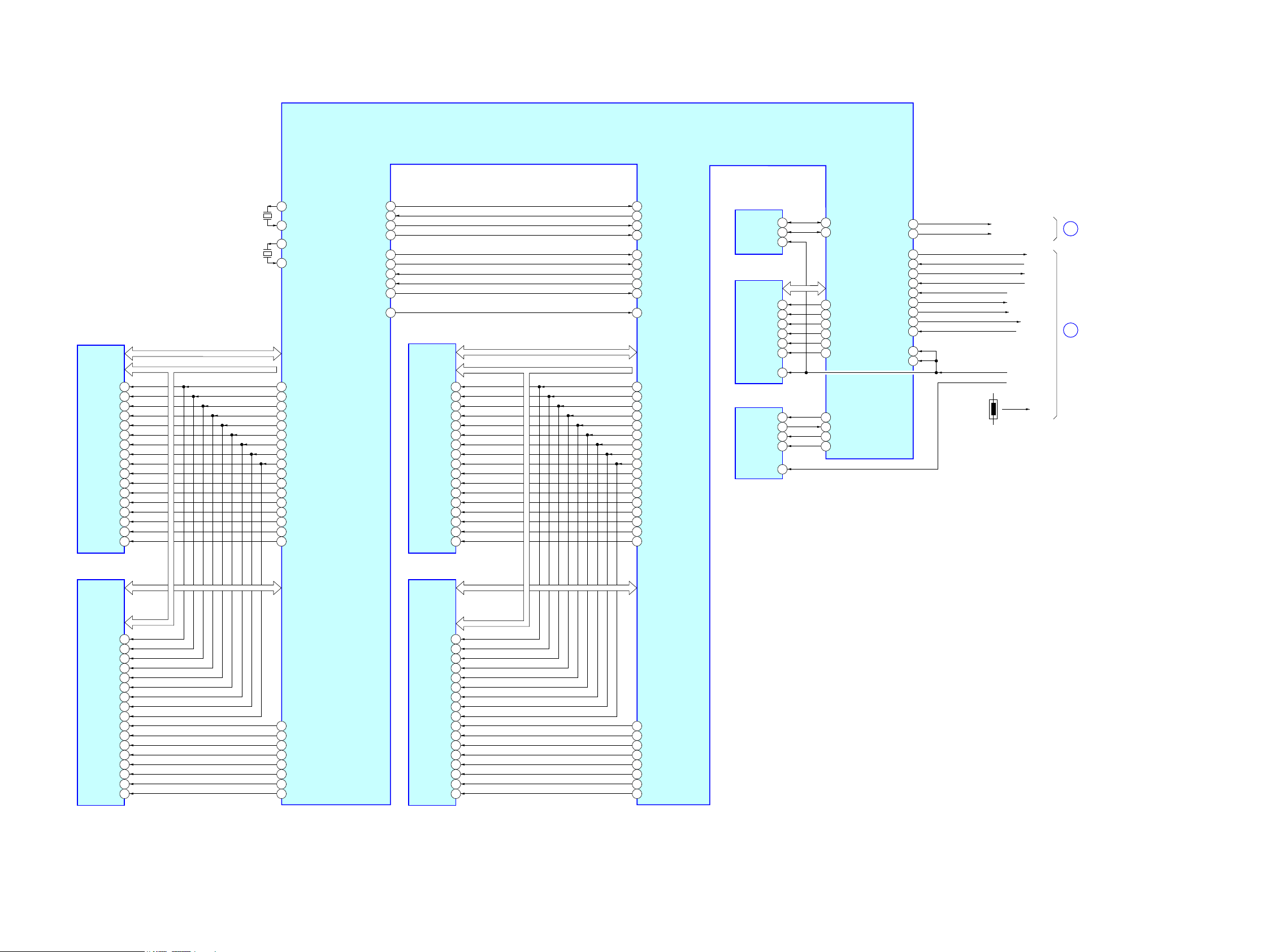
5-2. BLOCK DIAGRAM - MEMORY Section -
SD-RAM
IC104
A_RWEB
A_RA0 - A_RA13
A_RDQ0 - A_RDQ15
A_RCSB
BC29
AV2 4
K3
L8
/WE
A_RBA0
BB28
L2
BA0
A_RBA1
AU27
L3
BA1
A_RBA2
AT2 8
L1
BA2
/CS
A_RCASB
A_RRASB
AU23
BB24
L7
K7
/CAS
/RAS
A_RCKE
BA29
K2
CKE
A_RCLK0
BC21
J8
CK
A_RCLK0B
BA21
K8
/CK
A_RDQM1
A_RDQS1
AV1 8
BC17
B3
B7
UDM
UDQS
A_RDQS1B
A_RDQM0
BA17
AT1 8
A8
F3
/UDQS
LDM
A_RODT
AW23
K9
ODT
A_RDQS0
AY1 6
F7
LDQS
A_RDQS0B
BB16
E8
/LDQS
A0 - A12, NC
DQ0 - DQ15
SD-RAM
IC105
A_RDQ16 - A_RDQ31
K3
L8
/WE
L2
BA0
L3
BA1
L1
BA2
/CS
L7
K7
/CAS
/RAS
K2
CKE
A_RCLK1
BA39
J8
CK
A_RCLK1B
BC39
K8
/CK
A_RDQM3
A_RDQS3
AU35
BC35
B3
B7
UDM
UDQS
A_RDQS3B
A_RDQM2
BA35
AV3 4
A8
F3
/UDQS
LDM
K9
ODT
A_RDQS2
BA33
F7
LDQS
A_RDQS2B
BC33
B_RWEB
B_RA0 - B_RA13
B_RDQ0 - B_RDQ15
B_RCSB
AC43
AD42
B_RBA0
AD40
B_RBA1
AD36
B_RBA2
AC39
B_RCASB
B_RRASB
AH40
AJ41
B_RCKE
AC41
B_RCLK0
AL43
B_RCLK0B
AL41
B_RDQM1
B_RDQS1
AM36
AR43
B_RDQS1B
B_RDQM0
AR41
AP38
B_RODT
AG41
B_RDQS0
AT4 0
B_RDQS0B
AT4 2
B_RDQ16 - B_RDQ31
B_RCLK1
N41
B_RCLK1B
N43
B_RDQM3
B_RDQS3
V36
U43
B_RDQS3B
B_RDQM2
U41
V38
B_RDQS2
W41
B_RDQS2B
W43
E8
/LDQS
A0 - A12, NC
DQ0 - DQ15
SD-RAM
IC204
K3
L8
/WE
L2
BA0
L3
BA1
L1
BA2
/CS
L7
K7
/CAS
/RAS
K2
CKE
J8
CK
K8
/CK
B3
B7
UDM
UDQS
A8
F3
/UDQS
LDM
K9
ODT
F7
LDQS
E8
/LDQS
A0 - A12, NC
DQ0 - DQ15
SD-RAM
IC205
K3
L8
/WE
L2
BA0
L3
BA1
L1
BA2
/CS
L7
K7
/CAS
/RAS
K2
CKE
J8
CK
K8
/CK
B3
B7
UDM
UDQS
A8
F3
/UDQS
LDM
K9
ODT
F7
LDQS
E8
/LDQS
A0 - A12, NC
DQ0 - DQ15
NAND FLASH
IC501
BD DECODER
IC101 (2/2)
NFD0 - NFD7
B_RA0 - B_RA13
A_RA0 - A_RA13
A_RA0 A_RA13
B_RA0 - B_RA13
NFWEN
G43
18
XWE
NFREN
M36
8
XRE
NFCEN
NFRBN
M38
P38
9
7
XCE
RY/XBY
NFALE
NFCLE
L37
K38
17
16
ALE
CLE
EEPROM
IC1101
SDA
AV1 4
13
I2C_SDA
SCL
AT1 2
12
I2C_SCL
4
RESET
FESFDO
A1
FESFDI
C3
FESFCK
FESFCS
D4
B2
FE_SFDO
E1
FE_SFDI
F2
FE_SFCLK
FE_SFCS#
C1
K6
FE_SRXP
AR1
FE_SRXN
AR3
FE_STXP
FE_STXN
AN1
AP2
STXP_1
BC3
FE_XTAL25MI
AJ3
VCLK25MI
AJ9
FE_RSTI
M6
MRESET_
C35
STXN_1
BA3
SRXP_1
SRXN_1
BC1
BB2
SERIAL FLASH
IC502
SFDO
SFDI
F42
H40
5
2
D
Q
SFCK
SFCS
G41
J39
6
1
C
S
19
XWP
IO1 - IO8
X802
25MHz
XTAL25MO
XTAL25MI
BA9
BB8
X401
27MHz
NS_XTALO
NS_XTALI
C25
A25
VIND5
F14
USB_VBUS_PCONT1
GPIO3
B18
USB_VBUS_PCONT2
LCDRD
G33
VDATA
B34
VCLK
A35
GPIO2
C19
GPIO1
A17
GPIO0
C17
IF_SDI
IF_SDO
OPWRSB
F34
FE_EJECT#
AH4
OPWRSB
FE_EJECT
IF_SCK
XIF_CS
IF_START_BIT
SYSCON_REQ
GPIO6
AV1 2
UPG_STATUS
TEMP
RESET_
SYSCON_RST
CPU_PRERST
E35
CORE_RESETB
AP4
TH1501
D
C
7
HOLD
(Page 32)
(Page 30)
HBD-E770W
HBD-E770W
3030
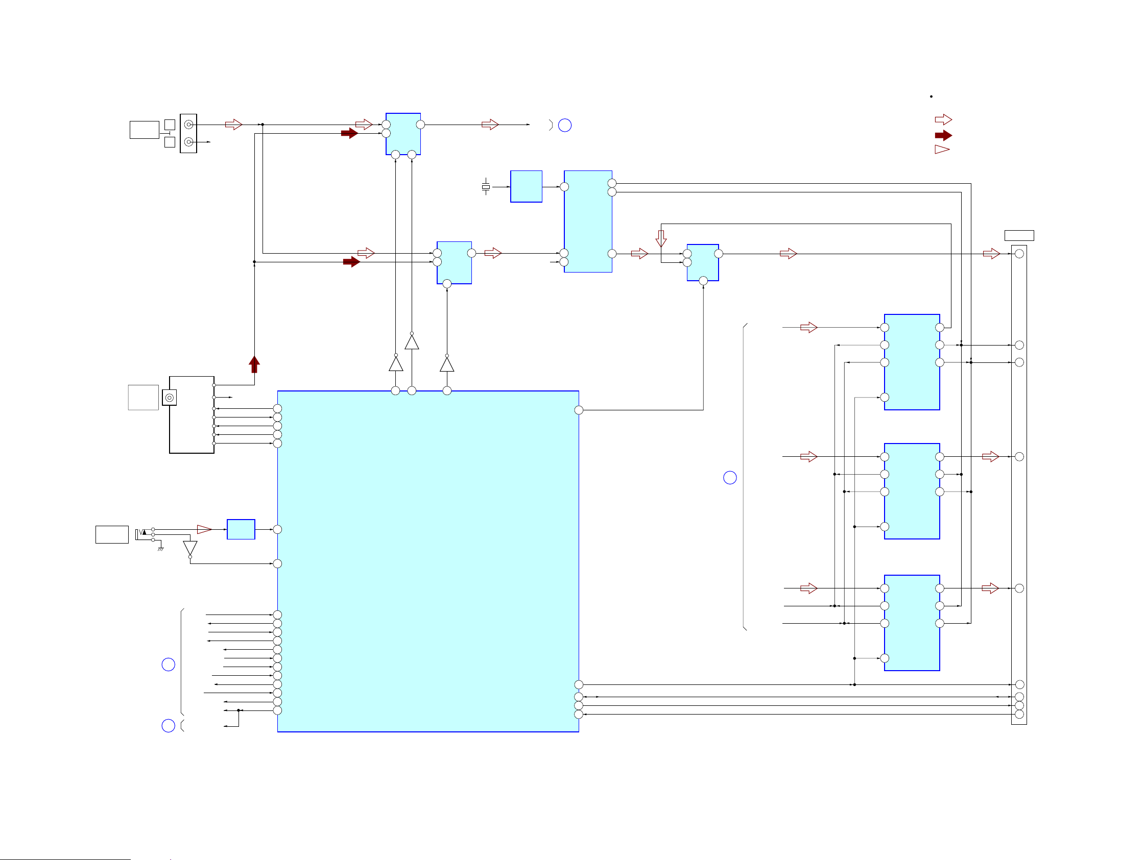
5-3. BLOCK DIAGRAM - TUNER, S-AIR Section -
6,*1$/3$7+
$8',2
781(5
0,&
5Y1
Y0
10
$
$8',26(/(&7
,&
3Y
5&+
/
5
$8',2
$8',2,1
J11
$&$/0,&
(&0$&
Q10
J10
0,&$03
,&
$17(11$
)0:
&2$;,$/
78
781(5)0
/&+
'2
&(
781('
',
&/
5&+ 5&+
$6(/B
9
B
$6(/B
Q14
Q13
Q13
$6(/B
6<67(0&21752//(5
,&
67B&(
67B&/.
67B'2
67B',
781('
$8/
(
5FKLVRPLWWHGGXHWRVDPHDV/FK
%'B5(6(7
35
6<6&21B567
&38B35(567
&38B35(567
,)B6',
,)B6'2
,)B6&.
;,)B&6
,)B67$57B%,7
6<6&21B5(4
7(03
'
6<6&21B567
B
%'B6'2
%'B6%,
%'B6&/.
49
%'B&6
%'B7(03
91
83*B67$786
83*B67$786
23:56%
23:56%
%'B,)B67$57
)(B(-(&7
)(B(-(&7
%'B,)B5(4
0,&B'(7
$FDOB/Y
1Y0
5Y1
$8',26(/(&7
,&
Y
10
$
1
6$,5B$'&B6(/
&1
(=:57
13
6',1B$QG
6',1B%6XUU
,17
14
,&B6'$
5(6(7
15
%&.
/5&.
11
,&B6&/
19
6',1B&6XUUEDFN
6$,5B'
6$,5B'
6$,5B'
6$,5B%&.
6$,5B/5&.
5&+
13
9,1/
9,15
%&.
/5&.
6&.,
14
$'
&219(57(5
,&
'287
9
'$7$6(/(&7
,&
1
$
B
5
Y
&/2&.
%8))(5
,&
6$03/(5$7(&219(57(5
,&
6$03/(5$7(&219(57(5
,&
9
3
6'7,
3'1
,%,&.
6'72
2%,&.
,/5&.2/5&.
9
3
6'7,
3'1
,%,&.
6'72
2%,&.
,/5&.2/5&.
F
6(/
;
0+]
6$03/(5$7(&219(57(5
,&
9
3
6'7,
3'1
,%,&.
6'72
2%,&.
,/5&.2/5&.
3
34
6$,5B*3,2
33
6$,5B6'$
30
6$,5B65&B567
6$,5B6&/
(Page 28)
(Page 29)
(Page 31)
(Page 31)
 Loading...