


FD Triniton KV-29FQ75A
Sony FD Triniton KV-29FQ75A, FD Triniton KV-29FQ75D, FD Triniton KV-29FQ75E, FD Triniton KV-29FQ75K Service Manual
SERVICE MANUAL
AE-5A
CHASSIS
MODEL
KV-29FQ75A
KV-29FQ75D
COMMANDER DEST CHASSIS NO.
RM-893 ET SCC-Q45A-A
RM-893 AE P SCC-Q41D-A
MODEL
KV-29FQ75E
KV-29FQ75K
COMMANDER DEST CHASSIS NO.
RM-893 ES P SCC-Q43A-A
RM-893 OIRT SCC-Q42B-A
1

TABLE OF CONTENTS
Section Title Page Section Title Page
Specifications .................... 3
Connectors .................... 4
Self Diagnostic Software .................... 5
1. GENERAL
Tuning your TV .................... 8
Finding your V ideo Channel .................... 8
NexT V iew .................... 8
T eletext .................... 9
Using the TV menu system .................... 10
Specifications .................... 14
Troubleshooting .................... 14
2. DISASSEMBLY
2-1. Rear Cover Removal .................... 15
2-2. Speaker Connector .................... 15
2-3. Chassis Removal .................... 15
2-4. Service Position .................... 16
2-5. D1 Board Removal .................... 16
2-6. J Board Removal .................... 16
2-7. B3 Board Removal .................... 16
2-8. Front Control Removal .................... 17
2-9. H3 and H6 Board Removal .................... 17
2-10. H5 Board Removal .................... 17
2-11. Service Connector .................... 17
2-12. Picture Tube Removal .................... 18
Bottom Plates .................... 19
3. SET-UP ADJUSTMENTS
3-1. Beam Landing .................... 20
3-2. Convergence .................... 21
3-3. Focus Adjustment .................... 23
3-4. Screen [G2], White Balance .................... 23
5. DIAGRAMS
5-1. Block Diagram (1) .................... 31
Block Diagram (2) .................... 35
Block Diagram (3) .................... 39
Block Diagram (4) .................... 43
5-2. Circuit Board Location .................... 46
5-3. Schematic Diagrams and
Printed Wiring Boards .................... 47
* H5 Board .................... 47
* F3 Board .................... 48
* F1 Board .................... 48
* H6 Board .................... 48
* E Board .................... 49
* M1 Board .................... 53
* D1 Board .................... 56
* D Board .................... 63
* A Board .................... 66
* J Board .................... 75
* C Board .................... 81
* BL Board .................... 85
* B3 Board .................... 88
* VM Board .................... 106
5-4. Semiconductors .................... 106
5-5. IC Blocks .................... 106
6. EXPLODED VIEWS
6-1. Chassis .................... 109
6-2. Picture Tube .................... 111
7. ELECTRICAL P ARTS LIST .................... 112
4. CIRCUIT ADJUSTMENTS
4-1. Electrical Adjustments .................... 24
4-2. V olume Electrical Adjustments .................... 28
4-3. T est Mode 2 .................... 29
CAUTION
SHORT CIRCUIT THE ANODE OF THE PICTURE TUBE AND THE
ANODE CAP TO THE METAL CHASSIS, CRT SHIELD, OR THE
CARBON PAINTED ON THE CRT, AFTER REMOVAL OF THE
ANODE CAP.
WARNING !!
AN ISOLATION TRANSFORMER SHOULD BE USED DURING ANY
SERVICE WORK TO AVOID POSSIBLE SHOCK HAZARD DUE TO
LIVE CHASSIS, THE CHASSIS OF THIS RECEIVER IS DIRECTLY
CONNECTED TO THE POWER LINE.
SAFETY-RELATED COMPONENT WARNING !!
COMPONENTS IDENTIFIED BY SHADING AND MARKED
THE SCHEMATIC DIAGRAMS, EXPLODED VIEWS AND IN THE
PARTS LIST ARE CRITICAL FOR SAFE OPERATION. REPLACE
THESE COMPONENTS WITH SONY PARTS WHOSE PART
NUMBERS APPEAR AS SHOWN IN THIS MANUAL OR IN
SUPPLEMENTS PUBLISHED BY SONY.
£
ON
ATTENTION
APRES AVOIR DECONNECTE LE CAP DE’LANODE,
COURT-CIRCUITER L’ANODE DU TUBE CATHODIQUE ET CELUI
DE L’ANODE DU CAP AU CHASSIS METALLIQUE DE L’APPAREIL,
OU AU COUCHE DE CARBONE PEINTE SUR LE TUBE
CATHODIQUE OU AU BLINDAGE DU TUBE CATHODIQUE.
ATTENTION !!
AFIN D’EVITER TOUT RISQUE D’ELECTROCUTION PROVENANT
D’UN CHÁSSIS SOUS TENTION, UN TRANSFORMATEUR
D’ISOLEMENT DOIT ETRE UTILISÈ LORS DE TOUT DÈPANNAGE
LE CHÁSSIS DE CE RÈCEPTEUR EST DIRECTMENT RACCORDÈ
Á L’ALIMENTATION SECTEUR.
ATTENTION AUX COMPOSANTS RELATIFS Á
LES COMPOSANTS IDENTIFIÈS PAR UNE TRAME ET PAR UNE
MARQUE
EXPLOSÈES ET LES LISTES DE PIECES SONT D’UNE IMPOR-
TANCE CRITIQUE POUR LA SÈCURITÈ DU FONCTIONNEMENT,
NE LES REMPLACER QUE PAR DES COMPSANTS SONY DONT LE
NUMÈRO DE PIÈCE EST INDIQUÈ DANS LE PRÈSENT MANUEL
OU DANS DES SUPPLÈMENTS PUBLIÈS PAR SONY.
£
SUR LES SCHÈMAS DE PRINCIPE, LES VUES
LA SECURITÈ!!
2
LEDOMMETI metsySnoisiveleT metsySoeretS egarevoClennahC metsySroloC
nailatIK/D,H/G/BoeretSNAMREG
PEAK/D,H/G/BoeretSNAMREG
hsinapSK/D,H/G/B
oeretS
MACIN/NAMREG
TRIOK/D,H/G/BoeretSNAMREG
ledoM A57QF92-VK
noitpmusnoCrewoPW431W851W851W851
ediWnortinirTDF
D57QF92-VK E57QF92-VK K57QF92-VK
tuptuodnuoS
)sehcni92(mc27xorppA
ebuTerutciP
derusaemerutcipmc86xorppA(
)yllanogaid
noitcelfedeerged401
refoowbuS
]RAER[slanimreTtuptuO/tupnI
.slangisoediVdnaoiduArofstupnI
rotcennocoruEnip-12:1
)dradnatsCELENEC(
.BGRrofstupnI
oiduAdnaoediVVTfostuptuO
snoisnemiDmm075x536x567xorppA
.slangis
.slangisoediVdnaoiduArofstupnI
rotcennocoruEnip-12:2
.oediVSrofstupnI
.slangisoiduAdnaoediVVTfostuptuO
thgieWgk95xorppA
)elbatceles(
.slangisoediVdnaoiduArofstupnI
rotcennocoruEnip-12:3
.oediVSrofstupnI
slangisoiduAdnaoediVrofstuptuO
)tuorotinom(
skcaJonohPoiduArofelbairavsrotcennoCtuptuO
serutaeFrehtO
slangiS
]TNORF[slanimreTtuptuO/tupnI
kcajenohpdaeHkcajinimoerets stnemeriuqerrewoP
stupnioiduAskcajonohp snoisnemiD)d/h/w(mm32x55x012xorppA
stupnioediVskcajonohp thgieW)yrettabgnidulcniton(g011xorppA
tupnioediVSNIDnip4
50S-10S,96R-12R,21R-10R:KD
50S-10S,96R-12R,21R-10R:KD
50S-10S,96R-12R,21R-10R:KD
50S-10S,96R-12R,21R-10R:KD
stnemeriuqeRrewoPV042-022
seirosseccAdeilppuS
metsyslortnocetomeRlortnocderarfnI
96E-12E:FHU21E-2E:FHVH/G/B
MACES,LAP
85.3CSTN,34.4CSTN
)NIOEDIV(
96E-12E:FHU21E-2E:FHVH/G/B
MACES,LAP
85.3CSTN,34.4CSTN
)NIOEDIV(
96E-12E:FHU21E-2E:FHVH/G/B
MACES,LAP
85.3CSTN,34.4CSTN
)NIOEDIV(
96E-12E:FHU21E-2E:FHVH/G/B
MACES,LAP
85.3CSTN,34.4CSTN
)NIOEDIV(
rekaepstfeLdnathgiR
)rewoPcisuM(W02x2
)SMR(W01x2
)SMR(W51x1)rewoPcisuM(W03x1
)1(rednammoCetomeR398-MR
)2(yrettab6RdetangisedCEI
esioN,retliFbmoClatigiD,weiVTxeN
CRD,erutciPzH001CRD,noitcudeR
resilauqEcihparG,erutciPzH05
cdV3
noitangisedCEIseirettab2
)AAezis(6R
.ecitontuohtiwegnahcottcejbuserasnoitacificepsdnangiseD
metI
emaNledoM
bmoClaPNONONONO
PIPFFOFFOFFOFFO
ytiroirPBGRNONONONO
xoBrefooWNONONONO
1tracSNONONONO
2tracSNONONONO
)3(nitnorFNONONONO
4tracSNONONONO
rotcejorPFFOFFOFFOFFO
edom9:61niBKANONONONO
G/BmroNNONONONO
ImroNFFOFFOFFOFFO
K/DmroNNONONONO
SUAmroNFFOFFOFFOFFO
LmroNFFOFFOFFOFFO
TASmroNFFOFFOFFOFFO
MmroNFFOFFOFFOFFO
txeteleTNONONONO
oeretSmaciNFFOFFONOFFO
A57QF92-VK D57QF92-VK E57QF92-VK K57QF92-VK
3
21 pin connector
21
19
17
15
13
11
9
7
5
3
1
20
18
16
14
12
10
8
6
4
2
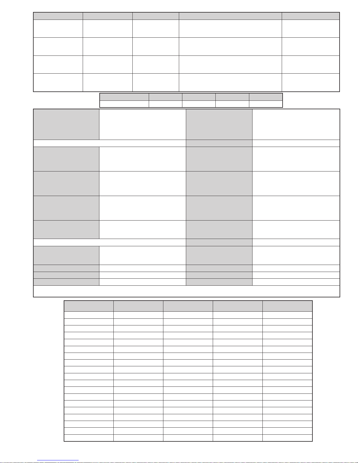
Pin No 1 2 4 Signal Signal level
1 Audio output B
2
3
4 Ground (audio)
5 Ground (blue)
6 Audio input A
7 Blue input 0.7 +/- 3dB, 75 ohms positive
8 Function select
9 Ground (green)
10 Open
11 Green Green signal : 0.7 +/- 3dB, 75 ohms,
12 Open
13 Ground (red)
14 Ground (blanking)
15
_ (S signal Chroma
16 Blanking input
17 Ground (video
18 Ground (video
19 Video output 1V +/- 3dB, 75ohms, positive sync 0.3V
20
_ Video input
21 Common ground
(right)
Audio output B
(right)
Audio output A
(left)
(left)
(AV control)
_ _ Red input 0.7 +/- 3dB, 75 ohms, positive
input)
(Ys signal)
output)
input)
_ _ Video input 1V +/- 3dB, 75ohms, positive sync 0.3V
Y (S signal)
(plug, shield)
Standard level : 0.5V rms
Output impedence : Less than 1kohm*
Standard level : 0.5V rms
Output impedence : More than 10kohm*
Standard level : 0.5V rms
Output impedence : Less than 1kohm*
Standard level : 0.5V rms
Output impedence : More than 10kohm*
High state (9.5-12V) : Part mode
Low state (0-2V) : TV mode
Input impedence : More than 10K ohms
Input capacitance : Less than 2nF
positive
0.3 +/- 3dB, 75 ohms, positive
High state (1-3V) Low state (0-0.4V)
Input impedence : 75 ohms
(-3+10dB)
(-3+10dB)
1V +/- 3dB, 75ohms, positive sync 0.3V
(-3+10dB)
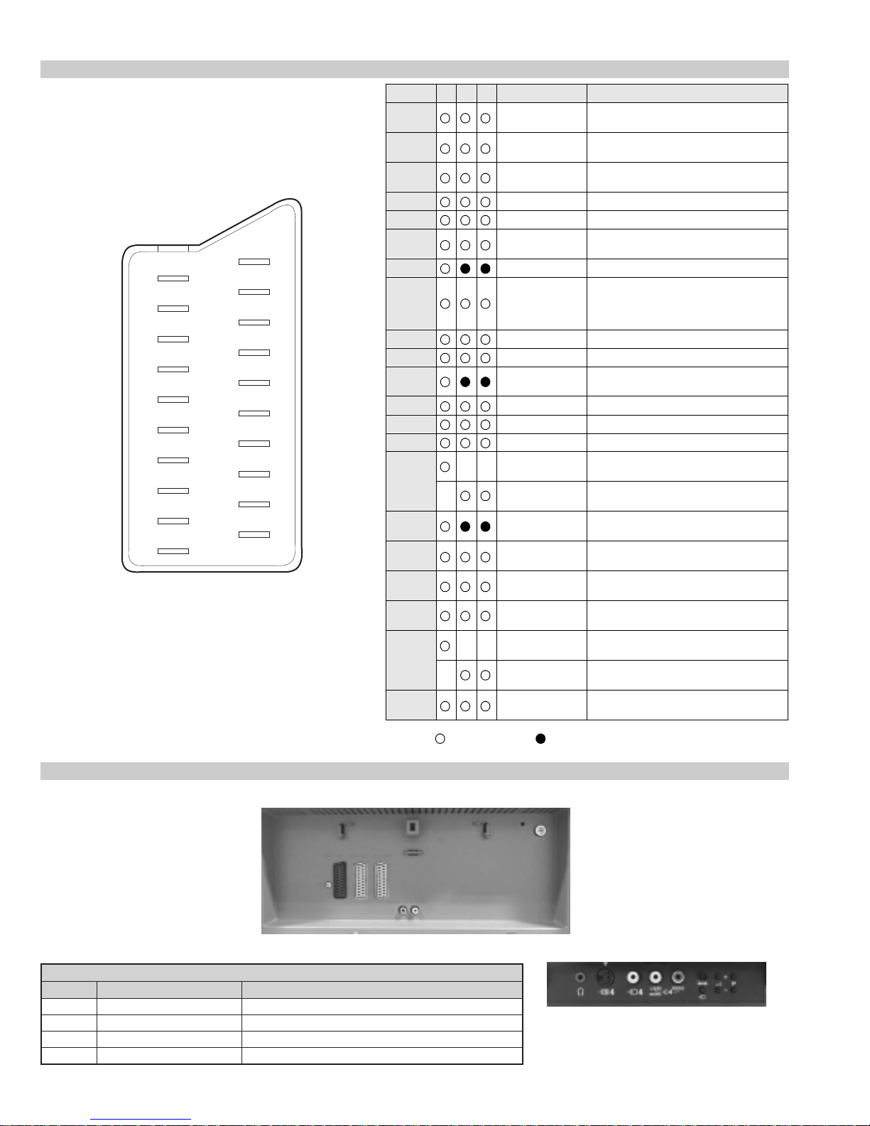
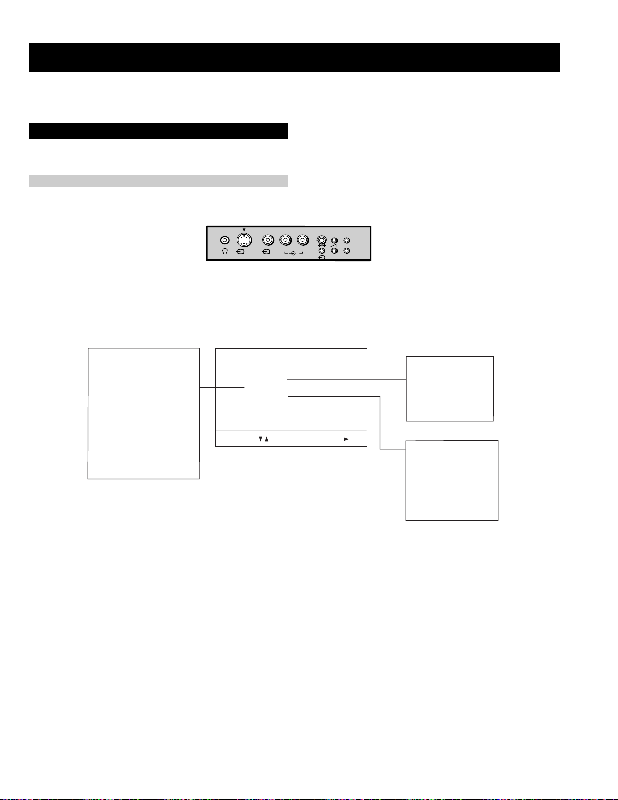
Rear Connection Panel
oNniP langiS leveLlangiS
1dnuorG2dnuorG3tupni)langisS(Y Bd01+3-V3.0.cnySevitisop,mho57Bd3-/+V1
4tupni)langisS(C.cnySevitisop,mho57Bd3-/+V3.0
Connected Not Connected (open) * at 20Hz - 20kHz
noitarugifnocniptekcosoediVS
S-Video
socket
4
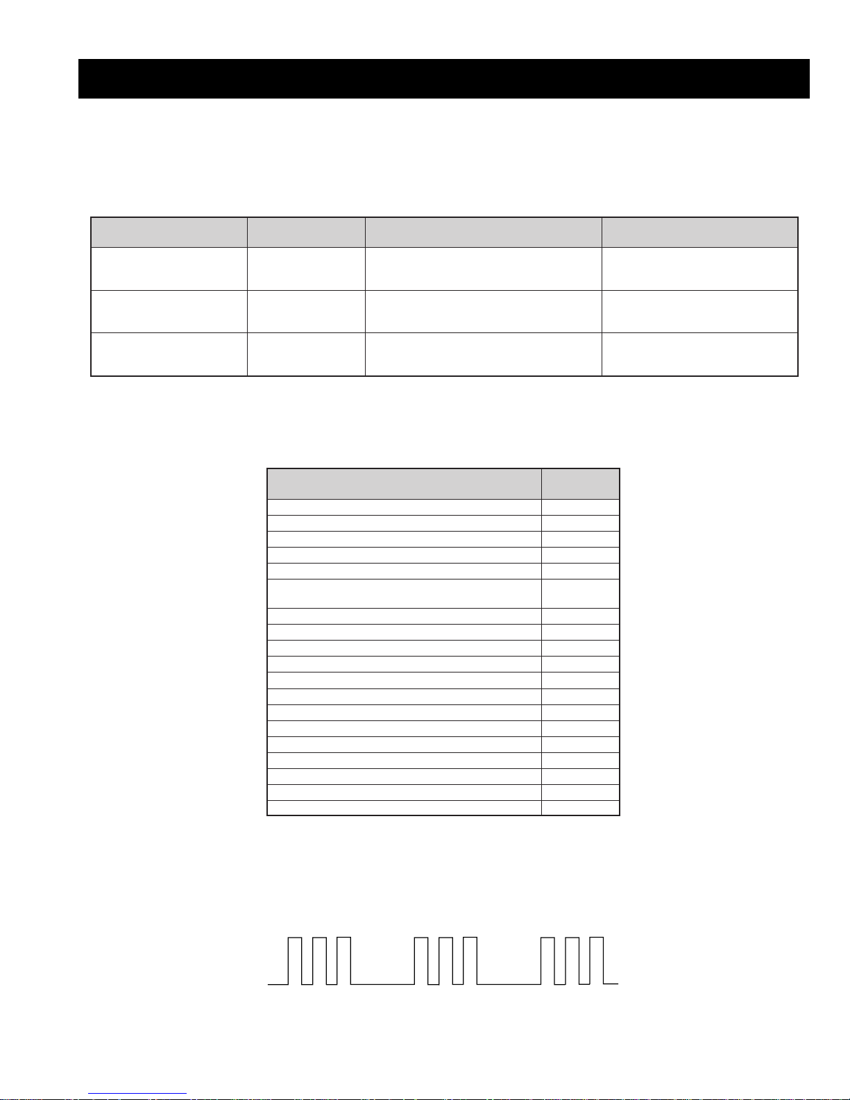
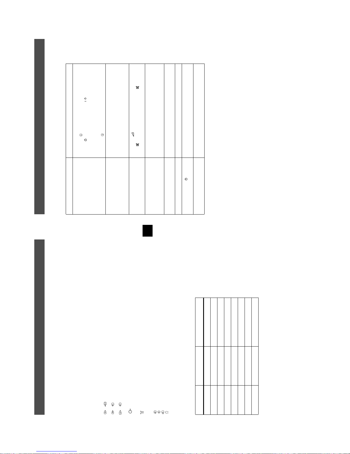
AE-5A SELF DIAGNOSTIC SOFTWARE
The identification of errors within the AE-5A chassis is triggered in one of two ways :- 1: Busy or 2: Device failure to respond to IIC. In the event of
one of these situations arising the software will first try to release the bus if busy (Failure to do so will report with a continuous flashing LED) and
then communicate with each device in turn to establish if a device is faulty. If a device is found to be faulty the relevant device number will be
displayed through the LED (Series of flashes which must be counted) See table 1., non fatal errors are reported using this method.
metIcitsongaiD
noitpircseD
nonruttonseodrewoPthgiltonseoD
)PCO(tnerrucrevOB+semit2
deppotsnoitcelfeDlacitreVsemit4
ybdnatSsemitfooN
sehsalFDEL
.tiucricneposiesuF
egasseMrorrE
rorreoN00
devreseR10
)noitcetorPtnerruCrevO(PCO20
)noitcetorPegatloVrevO(PVO30
noitcetorPlacitreV40
)26TTelbasid
noitcetorPlatnoziroH60
noitcetorPrekaepS70
rorre0subC2I80
redoceD-txeT-eleTB-M90
MVN,23C42TSB-M01
redoceDruoloCniaM,0239ADTB-J11
xoBerutaeFB-2B/1B21
retrevnoC-A/DB-1B31
dnekcaBB-E41
rossecorPdnuoS,D0143PSMB-J51
ediWotuA,7502DXCB-J61
MARlanretxE71
esuacelbaborP
noitacoL
.nideggulptonsidrocrewoP
)draoBD(.detrohssiCIrewoP4066CI
)draoBD(detrohssi0076CI
16TTelbane,s'03retfastratskcehc(BKAelbatsnU
smotpmySdetceteD
noemoctonseodrewoP
VTehtotdeilppussirewopoN
ytluafsiylppusrewopCA
)draoBD(.detrohssi)4086/3086Q(TUO.H
)draoBD(.detrohssi)6086Q(TEFytiraeniL
)draoBD(nepo5386RdeilppustonsiV51+
)draoBD(nepo4386RdeilppustonsiV51-
DEL
edoC
50
noemoctonseodrewoP
detrohssahenilrewopnodaoL
deppotssaheslupnoitcelfedlacitreV
detrohssahenilrewoP
Flash Timing Example : e.g. error number 3
StBy LED
ON ON ON
OFF
OFF
5

Error Detection Monitor
Device acknowledge is used to check IIC errors. Device acknowledge is checked by sending an IIC start sequence during CRT power on. Each
device is checked three times, if there is no acknowledge after each attempt, it will be regarded as an error.
There are three steps to check for errors.
1. IIC line 0
If all devices except the NVM have errors, IIC line 0 error is displayed.
2. Board check
If all devices mounted on one board have errors, board error is displayed.
3. Each device check
If IIC line error and board error are not detected then the device with the error is displayed.
The detected errors can be displayed as follows :
1. Error Monitor Menu.
2. Error Reader .
1. Error Monitor Menu
ERROR MONITOR
1. IGNORE ERRORS OFF ON OFF
Operating Time : 000075 h 15 min
Stored Errors :
1. D1 - B CXA1875 or MB88141
2. No Error Occured
3. No Error Occured
4. No Error Occured
5. No Error Occured
Current Error :
Start Error Sequence
Last menu Enter Item
6

2. Error Reader Display
The error reader display is connected to the service connector to read actual error codes. The part number for the error reader display is
S-188-900-10. Once an error has been detected it will then be displayed on the two digit error reader. The errors displayed refer to the following
table.
edoCrorrE egasseMrorrE
h000derruccororreoN
h1000CII,rorresuB
h2001CII,rorresuB
h001 draoB-A
h101rednapxEtroP,5781AXCB-A
h201renuTniaM,6231UTB-A
h301renuTbuS,0531UTB-A
h002 draoB-1B
h102,0829ADS.B-1BxoBerutaeF,456C38PB-1B
h202B-1B
h003 draoB-2B
h103CISEB,7794AAS.B-2B
h203yromeMdleiF,X594AAS.B-2B
h004 draoB-3B
h104X-DIM.B-3B
h204amaronaP.B-3B
h304CRD.B-3B
h404retsooBerutciP.B-KB
h005 draoB-1D
h105rotrevnoCcimanyD,0708AXCB-1D
h205rednapxEtroP,5781AXCB-1D
h006 draoB-E
h106dnekcaB,0012DXCB-E
h007 draoB-J
h107ediWotuA,7502DXCB-J
h207PIP,8829ADSB-J
h307redoceDruoloCbuS,0239ADTB-J
h407redoceDruoloCniaM,0239ADTB-J
h507dnuoS-buS,5781AXCB-J
h607reifilpmA-PH,9037ADTB-J
h707hctiwSoiduA,TD2246AETB-J
h807rossecorPdnuoS,D0143PSMB-J
h907PSDdnuoS,F7339CTB-J
hA07hctiwSVA,96X12AXCB-J
h008 draoB-M
h108MVN,23C42TSB-M
0829ADS.B-1BxoBerutaeF,456C38P
rotrevnoCA/D
rotrevnoCA/D,
7
SECTION 1 GENERAL
8
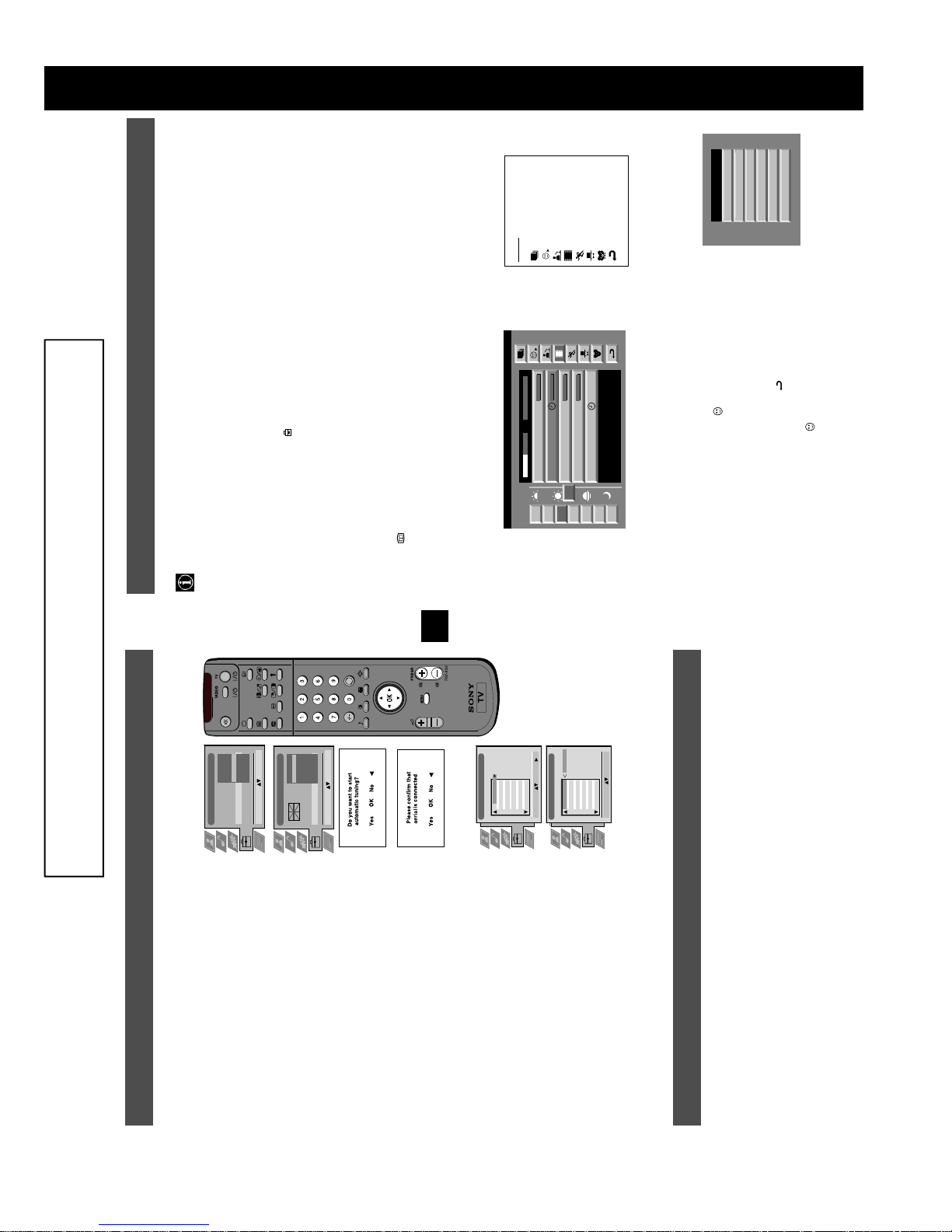
Operation
NexTView is an on-screen electronic programme guide, providing you with programme information for different
broadcasters.
NexTView*
Selecting your NexTView provider
Your TV set automatically selects the best NexTView provider for you. This provider is available about 30 minutes after the
channel tuning. You can however change this selection of provider if you wish.
1. Press the MENU button on the remote control to display the menu on the TV screen.
2. Press the v or V buttons to select the symbol on the menu screen then press B to enter the ‘Set Up’ menu.
3. Press v or V to highlight ‘Select NexTView’ then press B to confirm. A list is displayed containing all available
NexTView providers.
4. Press v or V to select the desired NexTView provider then press the OK button to store.
5. Press the MENU button to remove the menu from the TV screen.
7
Tue
07 Tue
12:38
8
Wed
10
Fri
11
Sat
12
Sun
13
Mon
9
Thu
12
SWISS
Star Wars
Super RTL
Fantasy film, USA, 1996
Werner - Beinhart
Pro 7
Flui grüsst den Rest der Welt
Kabel 1
Once upon a time in the West
Euronews
International News
RTL Plus
10:35 - 12:45
10:20 - 12:00
10:45 - 10:50
11:00 - 11:20
11:45 - 12:50
TXT TPS / RINGIER
Tue 07. 04 .98
Displaying NexTView
1. Press the button repeatedly on the remote control to switch NexTView on and off.
* In some cases, you may also need to press the b button to display the Sony electronic programme guide.
2. Press the v, V, b or B buttons to move the cursor around the screen.
3. Press the OK button to confirm a selection.
a. If you press the OK button in the date, time or icon (themes) columns, you change the programme list according to the
selection.
b. If you press the OK button in the programme list, you directly display the channel if the broadcast is currently running,
or, you display the ‘Long Info’ menu if the broadcast is running at some future time.
Index
full selection list
personal selection
news broadcasts
movies
sports
entertainment
children
return to last menu
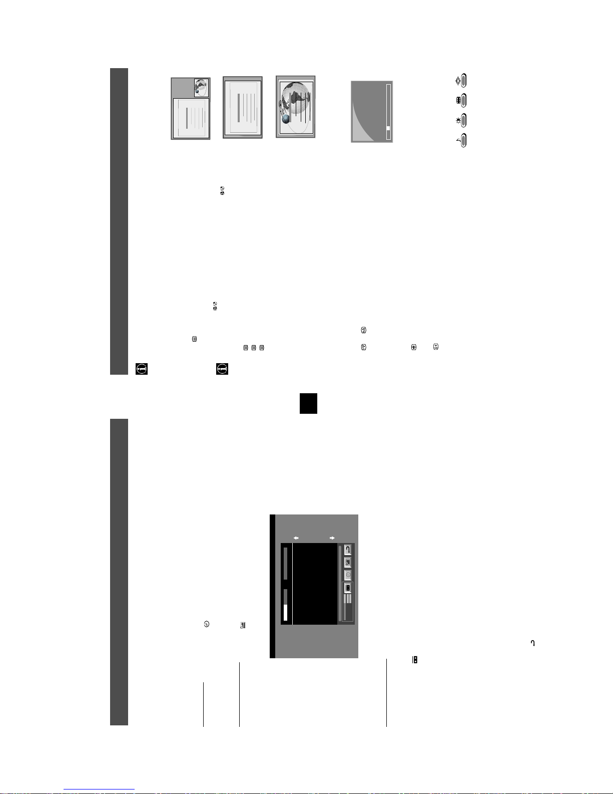
Using the ‘Individual Setting’ menu
You can make a personal list of the types of programmes you wish to view on the
programme guide.
1. Press the v or V buttons to select the icon then press B to display the
‘Individual Setting’ menu.
2. Press v or V to select your chosen item on the screen then press the OK button to
confirm your choice.
3. Repeat step 2 for all the items you wish to have in your list.
4. When you have finished the list, press
B
to select on the menu screen.
5. Press the OK button to return to the previous menu.
6. Press the v or V buttons to select the icon then press the OK button again to
activate your ‘Individual Setting’ filter.
Movie
Individual Setting
Comedy
Adult
News
Interview
Entertainment
* depending on availability of service
The operating instructions mentioned here are partial abstracts from the ‘Operating
Instruction Manual’. The page numbers of the ‘Operating Instruction Manual’ remain
as in the manual.
Installation
6. Tuning your TV
Before you tune your TV, you will be asked to set your language and coun try.
5
eština
Dansk
Italiano
English
Español
Deutsch
Français
Language
Country
Language/Country
chosen language then press the OK button to confirm. The
word ‘English’ highlighted.
1. The Language/Country menu appears on the TV screen with the
2. Press the v or V buttons on the remote control to select your
Confirm: OK
Language/Country
Select Language:
country menu appears on screen with the word ‘OFF’ highlighted.
Select ‘OFF’ if you do not want your channels stored in a given
France
Greece
Finland
Denmark
Germany
Czech Rep.
Confirm: OK
Great Britain
Language
Country
:
:
Select Country:
:
:
TV 5
PRO 7
EU-SP
SWF
RTL
SAT
MDR
DDI
C03
C05
C07
C08
C09
C11
C12
C13
1 2 3 4 5 6 7 8 91011
PROG CH LABEL
Programme Sorting
C03 TV 5
DSF
RTL 2
KAB 1
TV 5
PRO 7
EU-SP
SWF
RTL
SAT
MDR
DDI
DSF
RTL 2
KAB 1
C14
C15
C16
C03
C05
C07
C08
C09
C11
C12
C13
C14
1 2 3 4 5 6 7 8 91011
PROG CH LABEL
Programme Sorting
Select Prog: Confirm:
C15
C16
Select Position: Move: OK
channel sequence starting from programme position 1.
the TV then press the OK button to confirm your choice.
language. Press the OK button to confirm.
button to confirm. The TV starts to automatically search and store
3. Press v or V to select the country in which you wish to operate
4. The ‘autotune’ menu appears on the TV screen in your selected
all available channels for you. This may take a few minutes -
5. Ensure the aerial is connected as instructed, then press the OK
please be patient and do not press any buttons.
Sorting’ menu appears on the TV screen enabling you to change
the order of the channel s on your TV. If you wish to change the
6. Once the TV has tuned all available channels the ‘Programme
channel order, press the v or V buttons to select the channel you
new programme number position for your selected channel then
press the OK button to confirm. The selected channel now moves
to its new programme position and the other channels move
accordingly. Repeat this procedure if you wish to sort the order of
want to move then press B. Press the v or V buttons to select the
other channels on your TV.
7. Press the MENU button to remove the menu from the TV screen.
channels.
8. Press the PROGR+/- or the numbered buttons to view the TV
press the OK button.
Note: If you would like to stop the autotune process at any stage,
7. Finding your video channel
section of this instruction manual.
If you have connected a VCR to your TV, you now need to find your video channel.
1. Press the PROGR+/- buttons on the TV remote control until your video picture appears on the TV screen.
Note: If you wish to move your video channel to a different programme position, refer to the ‘Re-arranging TV channels’
8
25
153
101
25
153
101
98
25
153
101
98
m
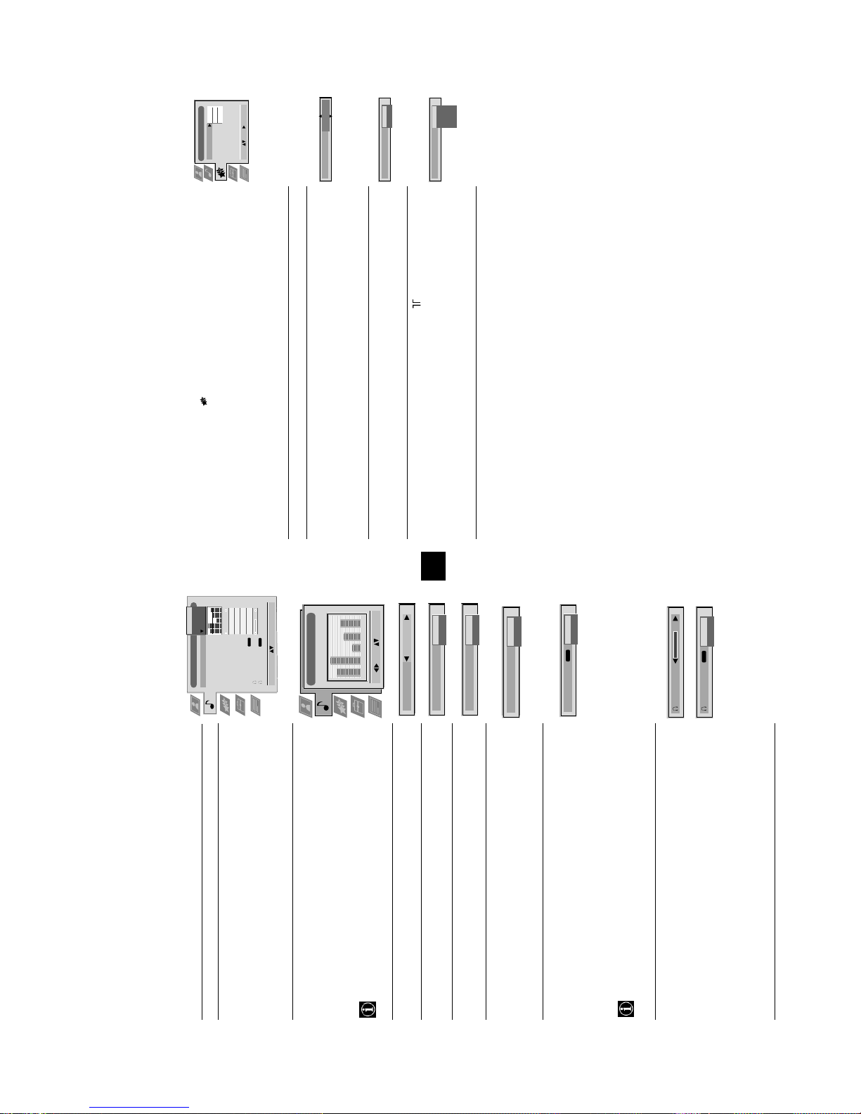
TELETEXT
In P&T mode press then press PROGR+/- to change the channel of the TV
Index
screen. Press b or B to change the size of the TV screen then press again to
resume normal teletext reception.
TELETEXT
Index
Programme
News
Sport
Weather
Most TV channels broadcast information via Teletext. The index page of the teletext service (usually page 100) gives you
information on how to use the service. Please use a TV channel with a strong signal, otherwise there may be Teletext errors.
Teletext
Operation
Switching Teletext on and off
with the TV channel in the right corner and the Teletext display on the left.
1. Select the TV channel which carries the teletext service you want to view.
2. Press the button once for Picture and Teletext (P&T). The screen is divided in two,
Programme
m
News
Sport
Weather
3. Press twice to get Teletext only.
4. Press three times for Mix mode.
5. Press a fourth time to switch off Teletext.
98
TELETEXT
Index
Programme
News
Sport
Weather
Selecting a Teletext page
Input three digits for the page number using the numbered buttons on the remote control. If
Press the or buttons on the remote control to select the previous or next p age.
01 03 04 05 06 07 0802
Selecting a sub page
A teletext page may consist of several su b pages. In this case an information line is displayed,
showing the number of subpages. Select the sub page by pressing v or V.
To freeze a Teletext page
Press the button to freeze the page. Press again to cancel the freeze.
Revealing the index page
several page numbers on it (eg the index page).
Using the feature ‘Page Catching’
page is displayed after s ome seconds.
1. Press the numbered buttons on the remote control to select a teletext page which has
2. Press the OK button.
Press the button to reveal the index page (normally page 100).
Using colour buttons to access pages (Fastext)
(only available if the TV station broadcasts Fastext signals)
When the colour coded menu appears at the bottom of a page, press a coloured button on the
remote control (green, red, yellow or blue) to access the corresponding page.
3. Press v or V to select the desired page number then press the OK button. The requested
10
216-02
you make a mistake, type in any three digits then re-enter the correct page number.
Using Other Teletext Functions
Selecting the next or preceding page
Tue 07. 04 .98
SWISS TXT TPS / RINGIER nexTView
First nextTView/EPG-Providers in Europe
07 Tue
12:38
Address Mapping
The position of the addresses in the
OSDA is shown in the following diagram.
The position values of the DPW are set
to '0'.
If other values are set, the complete
combination will be scrolled.
SP
On
VCR1
This channel has been set for a timer
Speed
Timer Prog
VPS/PDC
Example:
if the DPWC is set to '63', the char-
9
NexTView
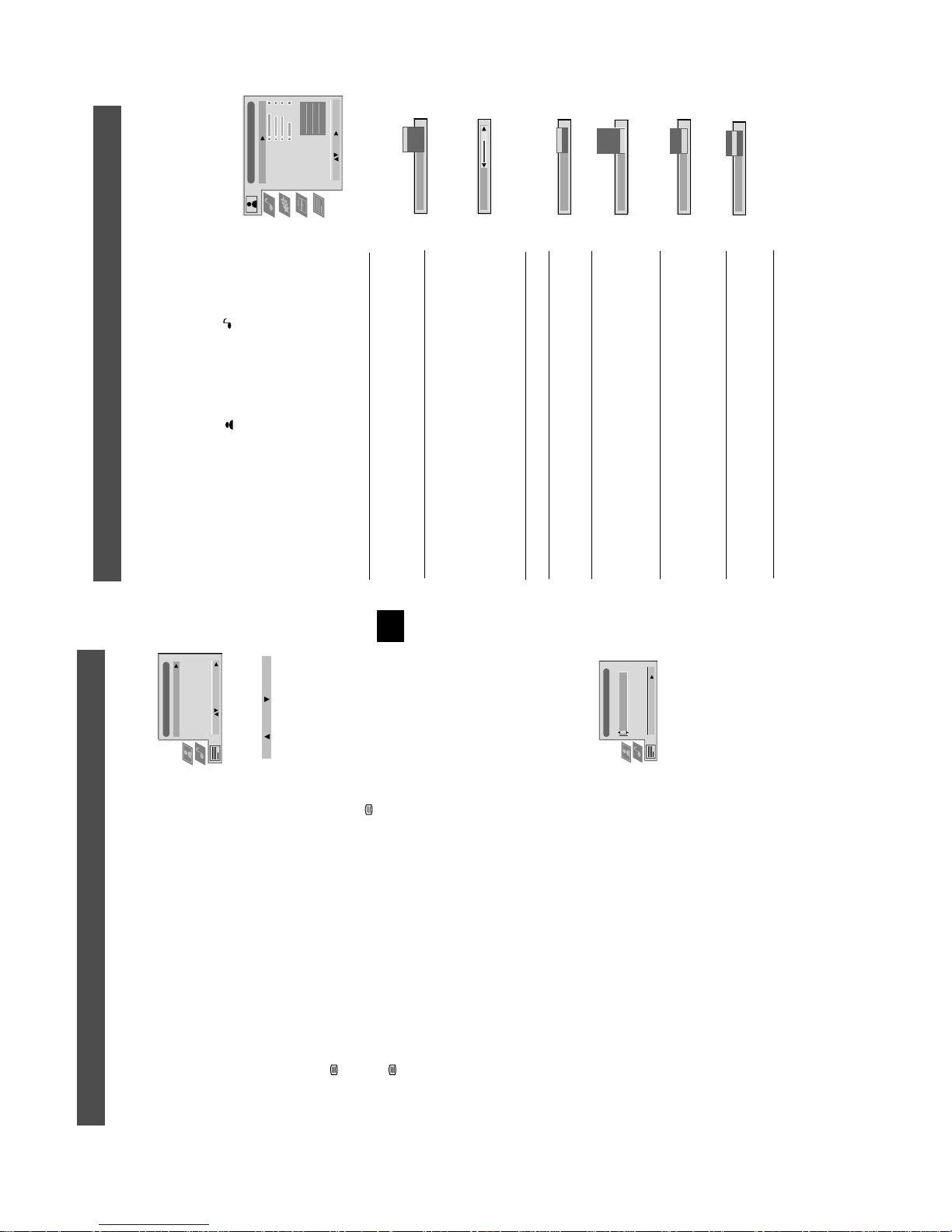
Operation
Using the ‘Long Info’ menu
With this ‘Long Info’ menu screen, you can set timers or record selected programmes.
1. Press v or V to select a future programme in the programme list column.
2. Press the OK button to display the ‘Long Info’ menu on the TV screen.
To set the timer
With longplay you can record twice as much on a videotape. The picture quality however may suffer.
VCR Setup
guaranteed recording of the whole broadcast should there be a change in the TV programme. This only works if the selected
channel broadcasts a VPS/PDC signal.
To view the timer table
Press the b or B buttons to highlight the icon then press the OK button repeatedly to ‘set the timer’ or ‘cancel the timer’. If
Press the b or B buttons to highlight the icon then press the OK button repeatedly to switch on/off the timer table. This tab le
shows the programmes on which you have already set a timer. (You can set a timer on up to 5 programmes).
To record programmes*
* (only with Smartlink VCRs)
3. To set up the VCR:
1. Connect your Smartlink VCR.
2. Press b or B to select then press the OK button to download the information to your VCR.
you choose to set the timer, the programme is marked with a clock symbol and a message appears on the screen shortly before
VPS/PDC
the programme is due to start asking whether you wish to still view this programme.
Speed
Press b to select VPS/P DC then press the OK button repeatedly to select ‘On’ or ‘Off’. With this setting on you hav e the
Press V to select ‘VCR Setup’ then press the OK button repeatedly to select which VCR you wish to programme, namely
Press V to select ‘Speed’ the press the OK button repeatedly to select between ‘SP’ for standard play or ‘LP’ for longplay.
‘VCR1’ or ‘VCR2’.
4. Finally, press B to select the icon then press the OK button to remove the menu from the TV screen.
9
Personal
Picture Adjustment
Picture Mode
Contrast
Brightness
Colour
On
On
Normal
DRC 100
Sharpness
ResetAINoise Reduction
Digital Mode
Colour Tone
Live
Movie
Game
Personal
Select: Enter:
Picture Mode
Contrast
On
Off
AI
Mid
High
Off
Low
Auto
Noise Reduction
Normal
DRC 50
DRC 100
Digital Mode
scrolling characters
Cool
Warm
Normal
Colour Tone
flicker-free pictures
according to the TV signal.
Using the TV menu system
Operation
The TV consists of a menu system which is based on a series of user friendly on-screen displays and menus. These displays will
help you get the most from your TV, helping you to change picture and sound settings, to alter the size of the TV picture and to
rearrange the TV channels etc.
Teletext
Top / Bottom / Full
Adjusting the picture and sound
Text Clear
v DRC 100: Optimum picture resolution creating
Normal: Normal.
v Cool: Gives a cool tint to the picture.
Colour Tone V Warm: Gives a warm tint to the picture.
12
Mid: Medium noise reduction.
Personal (for individual settings)
Movie (for movie broadcasts)
Low: Low noise reduction.
v Game (for computer games)
confirm. For a description of the menu items and their effects, see the table below.
press B to enter either the ‘Picture Adjustment’ menu or the ‘Audio Adjustment’ menu.
4. Press the v, V, B or b buttons to adjust your selected item.
5. As soon as you have adjusted the item, press the OK button to store the new setting.
6. Repeat steps 3-5 if you wish to adjust any of the other items.
1. Press the MENU button on the remote control to display the menu on the TV screen.
2. Press the v or V buttons to select for picture settings or for sound settings then
The picture and sound are preset at the factory. You can however adjust them to suit your own taste.
3. Press the v or V buttons to select the item on the screen you wish to adjust then press B to
7. Press the MENU button to remove the menu from the TV screen.
Picture Control
Item Effect/Operation
Picture Mode V Live (for live broadcasts)
Contrast Less bB More
Brightness* Darker bB Brighter
Colour* Less bB More
Hue** Reddish bB Greenish
Sharpness* Softer bB Sharper
*Only available if ’Personal’ is selected in ‘Picture Mode’
**Only available for NTSC colour signal (eg. US video tapes)
Reset Resets picture to the factory preset levels
(Artificial Intelligence) v On: Automatic optimization of contrast level
AI V Off: Normal
Noise Reduction V High: High noise reduction.
DRC 50: Improved picture resolution for viewing
Auto: Optimum noise reduction automatically selected.
v Off: No noise reduction.
Digital Mode V Normal: Basic 100Hz picture quality
11
- - : - -– – –
Select: Enter Menu:
Reveal
Time Page
Page Overview
Top: Bottom: Full: OK
Time Page
PAGE TIME
Select Page: 0-9 Next:
menu on the TV screen.
Teletext
Operation
Using the Teletext menu
sub menu.
Text Clear*
*available on Teletext Only and Mix modes (Refer to ‘Switching Teletext on and off’)
1. With Teletext switched on, press the MENU button on the remote control to display the
2. Press v or V to select your chosen item on the screen then press B to display the relevant
3. To remove the Teletext menu from the screen, press the MENU button.
button to restore the page to normal size. Press b to return to the Teletext menu screen.
Top/Bottom/Full
The Top/Bottom/Full sub menu allows you to enlarge different sections of the Teletext page.
Press v to enlarge the upper half of the screen, Press V to enlarge the lower half. Press the OK
symbol will appear in the top left hand corner of the screen.
3. Press v or V to highlight ‘Text Clear’ and press B to select.
4. The current TV channel is displayed. Once the text page has been found a blue
1. Press the button on the remote control twice to select full screen text.
2. Press the MENU button to display the ‘Teletext’ menu.
Text Clear is a function that displays a TV channel while a Teletext page is being searched for.
5. Press the button on the remote control to view the page.
Reveal
Some Teletext pages contain hidden information (eg for a quiz), which can be revealed.
1. In text mode press the MENU button on the remote control to access the ‘Teletext’
menu.
2. Press v or V to highlight ‘Reveal’ and press B to select. The hidden information is
displayed on the screen.
Time Page*
displayed.
displayed in the top left hand corner of the screen. At the requested time the desired p age
2. Press v or V to highlight ‘Time Pa ge’ and press B to select. The ‘Time Page’ sub menu is
is displayed.
1. In Text mode press the MENU button on the remote control to access the ‘Teletext’ menu.
3. Enter the desired page number using the numbered buttons on the remote control.
4. Enter the desired time using the remote control.
*depending on availability of service,Time Page is available on Teletext Only and Mix modes
Time Page allows a time-coded Teletext page (such as an alarm page), to be displayed at a set
time.
5. Press OK to confirm the settings. The TV will exit Teletext mode and the time will be
Page Overview*
*only available if TOP-Text is transmitted by the TV station.
In this menu the TOP-Text pages are divided into two columns, the first column showing
3. Press the OK button to display the chosen pages.
2. Press v or V to select the relevant ‘group’ or ‘block’ of pages.
1. Press b or B to select the first or second column.
‘blocks’ of pages and the second showing ‘groups’ of pages.
10
TV
Off
Off
10 min
Off
On
TV
AV 2
AV 3
AV 4
AV 1
Features
Sleep Timer
Parental Lock
AV 2 Output
Select: Enter:
Sleep Timer
Parental Look
AV 2 Output
standby mode. The buttons on the TV do not work.
AV1 audio/video signa l from scart 1
AV2 audio/video signa l from scart 2
standby mode.
V Off
v 90 min
v On: Press the buttons on the remote control to switch the TV out of
menu.
1. Press the MENU button on the remote control to display the menu on the TV screen.
Using the TV menu system:
Using the Features menu
of the menu items and their effects, see the table below.
2. Press the v or V buttons to select for the ‘Features’ menu then press B to enter the ‘Features’
3. Press the v or V buttons to select the desired menu item then press B to confirm. For a description
4. Press the v, V, B or b buttons to select the desired setting.
5. Press the OK button to confirm your choice of setting.
6. Repeat steps 3-5 if you wish to select any of the other items.
7. Press the MENU button to remove the menu from the TV screen.
Item Effect/Operation
Sleep Timer You can select a time after which the TV switches itself into
Parental Lock V Off: Normal
AV3 audio/video signal from scart 3
v AV4 audio/video signal from connectors on front of TV
14
AV2 Output V TV audio/video signal from the aerial
13
Off
Off
Off
Jazz
Rock
Vocal
Personal
Audio Adjustment
Equaliser Mode
Using the TV menu system:
Sound Control
Equaliser
Adjustment
Item Effect/Operation
0
Balance
Equaliser Mode V Personal
Loudness
Space
Vocal
Auto Vol. Control
Stereo
Stereo
Confirm: OK
NICAM
NICAM
Select Mode :
Dual Sound
Volume
Dual Sound
Jazz
Rock
Pop
v Flat (fixed setting, cannot be adjusted)
(Personal)
Equaliser Adjustment
+
adjust the frequency. Finally, press the OK button to store
the new adjustment.
cutting and boosting the 5 selected frequency bands.
Press b or B to select the frequency band then V or v to
Equaliser adjustment You can adjust the mode selected in Equaliser mode by
Off
On
Off
On
Off
On
120 500 1,5K 5 K 10 K
Sel: Adjust: Confirm:OK
0
–
If you want to store the new setting, you need to set the Equaliser mode to
‘Personal’. Personal mode permanently stores the setting, all other modes (Vocal,
Jazz, Rock, Pop) store only until the next mode change.
Balance0Loudness
B More right
Balance b More left
Loudness V Off: Normal
Space
Auto Vol. Control
independent of the broadcast signal (eg in the case of
advertisements)
v On: For music broadcasts
v On: Special acoustic effect
Space V Off: Normal
v Off: Volume level changes according to the broadcast
Auto Vol. Control V On: Volume level of the channels will stay the same
Mono
Stereo
NICAM
Dual Sound
signal.
V A for channel 1
v B for channel 2
For a stereo broadcast:
V Mono
v Stereo
When NICAM stereo is being broadcast, the indication NICAM appears briefly
on the screen.
Dual Sound For a bilingual broadcast:
Headphones
Volume
i Volume Less bBMore
i Dual Sound Only available when PAP feature is selected:
PAP
Stereo
NICAM
Dual Sound
the TV loadspeakers and the headphones.
V Stereo: The sound of one screen comes through both
the TV loudspeakers, the sound of the right
screen is selectable via headphones.
v PAP: The sound of the left screen comes through
For more detail on PAP, refer to the ‘Operating PAP’ section of this manual.
11
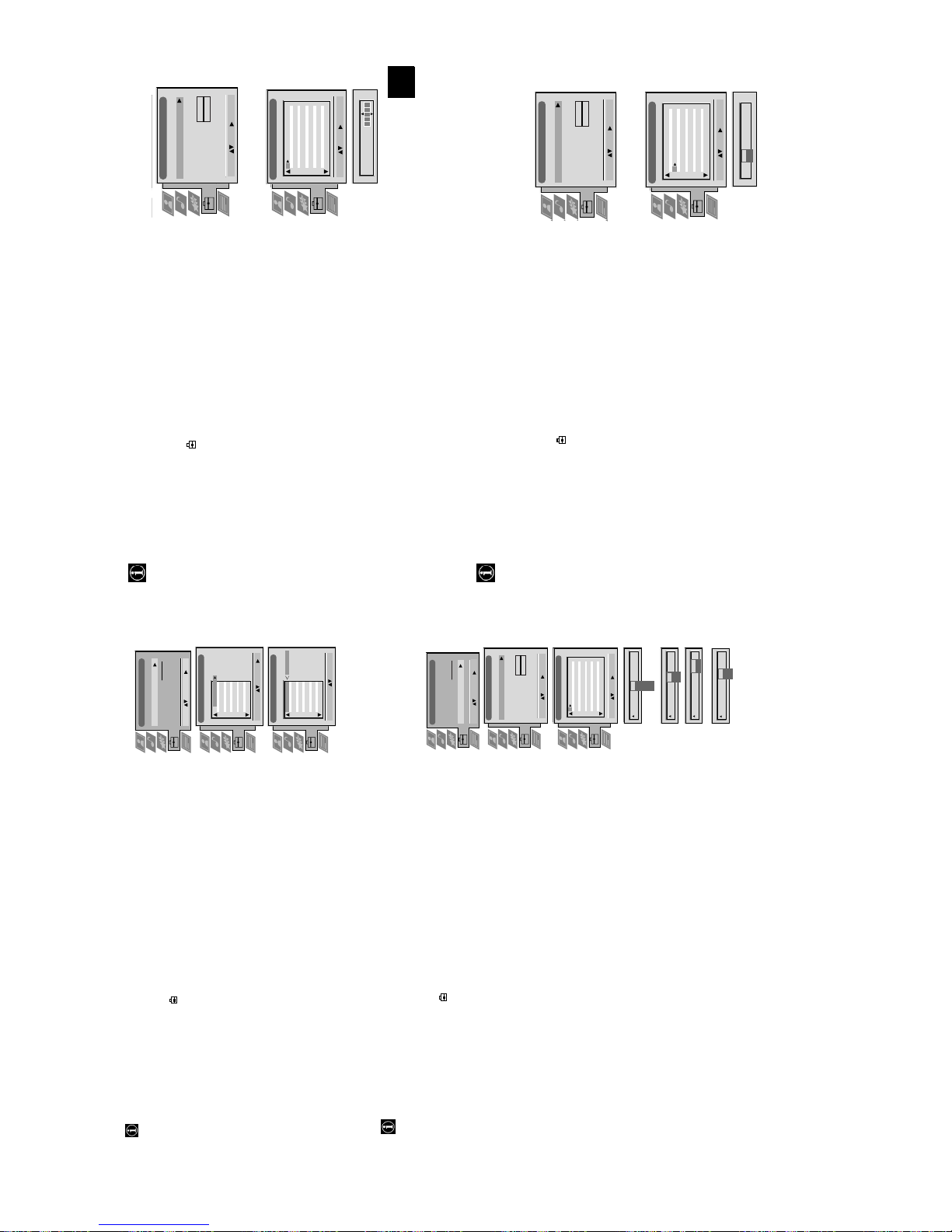
Manual Set Up
Manual Set Up
Language/Country
Language/Country
Manual Programme Preset
Manual Programme Preset
Further Programme Preset
O
O
RGB Set Up
Picture Rotation
Further Programme Preset
RGB Set Up
Picture Rotation
- - - - - - -
- - - - - - -
Personal ID
Demo
Personal ID
Demo
O
Manual Set Up
Language/Country
Manual Set Up
Language/Country
Manual Programme Preset
Manual Programme Preset
O
Further Programme Preset
RGB Set Up
Picture Rotation
Further Programme Preset
RGB Set Up
Picture Rotation
- - - - - - -
- - - - - - -
Personal ID
Demo
Personal ID
Demo
BBC1
BBC
C09
C10
I
I
Off
Off
Off
Off
Off
Off
Off
Off
Select: Enter:
Select: Enter:
5152535455565758596061
Manual Programme Preset
PROG CHSYSSKIP LABEL
F189 - - - Off
Off
Off
On
Off
53 I
Select: Enter:
PROG CHSYSSKIP LABEL
17
ARD
BBC
C09
C10
B/G
B/G
Off
Off
Off
Off
Off
Off
Off
Off
Off
Select: Enter:
Select: Enter:
1 2 3 4 5 6 7 8 91011
Manual Programme Preset
PROG CHSYSSKIP LABEL
C07 TE
Off
Off
Off
SKIP LABEL
6 I
Select: Enter:
PROG CHSYS
Using the TV menu system:
Naming a channel
Names for channels are usually taken automatically from Teletext if available. You can however name a channel or an input
Set Up
video source using up to five characters (letters or numbers).
Auto Tuning
1. Press the MENU button on the remote control to display the menu on the TV screen.
- - - - -
Programme Sorting
Select NexTView
AV Preset
Manual Set Up
Select: Enter :
2. Press the V button to select the symbol on the menu screen then press B to enter the ‘Set
Up’ menu.
PROG CH LABEL
Programme Sorting
menu.
3. Press the V button to select ‘Manual Set Up’ then press B to enter the ‘Manual Set Up’
TV 5
PRO 7
EU-SP
SWF
RTL
SAT
MDR
DDI
C03
C05
C07
C08
C09
C11
C12
C13
1 2 3 4 5 6 7 8 91011
Programme Preset’ menu.
4. Press the V button to select ‘Manual Programme Preset’ then press B to enter the ‘Manual
5. Press the v or V buttons to select the channel you wish to name.
C03 TV 5
DSF
RTL 2
KAB 1
TV 5
PRO 7
EU-SP
SWF
RTL
C14
C15
C16
SAT
C03
C05
C07
C08
C09
C11
1 2 3 4 5 6 7 8 91011
PROG CH LABEL
Programme Sorting
Select Prog: Confirm:
confirm. Select the other four characters in the same way.
8. After selecting all the characters, press the OK button.
9. Repeat steps 5 to 8 if you wish to label other channels.
6. Press the B button repeatedly until the first element of the ‘LABEL’ column is highlighted.
7. Press the v or V buttons to select a letter or number (select ‘-’ for a blank) then press B to
MDR
DDI
DSF
RTL 2
KAB 1
C12
C13
C14
C15
C16
Select Position: Move: OK
10. Press the MENU button to remove the menu from the TV screen.
Set Up
This function enables you to skip unused programme positions when selecting them with the PROGR+/- buttons.
However, by using the number buttons you can still select the skipped programme position.
Skipping programme positions
O
Manual Set Up
Language/Country
Manual Programme Preset
Further Programme Preset
- - - - - - -
RGB Set Up
Picture Rotation
Personal ID
- - - - -
Select: Enter :
Auto Tuning
Programme Sorting
Select Next View
AV Preset
Manual Set Up
‘Set Up’ menu.
1. Press the MENU button on the remote control to display the menu on the TV screen.
2. Press the V button to select the symbol on the menu screen then press B to enter the
ARD
BBC
TV 5
PRO 7
EU-SP
SWF
RTL
SAT
C03
C05
C07
C08
C09
C11
C09
C10
B/G
B/G
B/G
B/G
B/G
B/G
B/G
B/G
Off
Off
Off
Off
Off
Off
Off
Off
1 2 3 4 5 6 7 8 91011
Select: Enter:
Manual Programme Preset
PROG CHSYSSKIP LABEL
Demo
Programme Preset’ menu.
‘SKIP’ column.
menu.
3. Press the V button to select ‘Manual Set Up’ then press B to enter the ‘Manual Set Up’
4. Press the V button to select ‘Manual Programme Preset’ then press B to enter the ‘Manual
MDR
DDI
DSF
C12
C13
C14
I
L
D/K
B/G
B/G
B/G
B/G
Off
Off
Off
EXT
Off
SKIP LABEL
Select: Enter:
1
PROG CHSYS
position) then press the OK button to store.
5. Press the v or V buttons to select the programme position then press B to highlight the
6. Press the v or V buttons to select ‘Off’ or ‘On’ (if you wish to skip this programme
7. Repeat steps 5 and 6 if you wish to skip or unskip further programme positions.
8. Press the MENU button to remove the menu from the TV screen.
AV1
03
SEARCH
CH
CH
AV1
AV2
F
S
C
Off
SKIP LABEL
1 I
PROG SYS
AV3
Off
SKIP LABEL
Off
SKIP LABEL
1 I
0 EXT
PROG SYS
PROG CHSYS
After tuning the TV, you can use this feature to change the order of the channels on the TV.
Using the TV menu system:
Re-arranging the TV channels
menu.
1. Press the MENU button on the remote control to display the menu on the TV screen.
2. Press the V button to select the symbol on the menu screen then press B to enter the ‘Set Up’
menu.
3. Press the V button to select ‘Programme Sorting’ then press B to enter the ‘Programme Sorting’
4. Press the v or V buttons to select the channel you want to move then press B to confirm.
channel then press the OK button to confirm. The selected channel now moves to its new
programme position and the other channels move accordingly.
5. Press the v or V buttons to select the new programme position (eg PROG 4) for your selected
6. Repeat steps 4 and 5 if you wish to sort the other channels.
Manually tuning the TV
7. Press the MENU button to remove the menu from the TV screen.
You have already tuned the TV automatically using the instructions at the start of this manual. You can however carry out
this operation manually, adding channels to the TV, one at a time.
menu.
1. Press the MENU button on the remote control to display the menu on the TV screen.
Set Up’ menu.
2. Press the V button to select the symbol on the menu screen then press B to enter the ‘Set Up’
3. Press the V button to select ‘Manual Set Up’ on the menu screen then press B to enter the ‘Manual
the ‘Manual Programme Preset’ menu.
4. Press the V button to select ‘Manual Programme Preset’ on the menu screen then press B to enter
then press B to highlight the ‘SKIP’ column.
5. Press the v or V buttons to select a programme number for your channel (eg PROGR 1 for BBC1)
to confirm.
D/K for eastern european countries) or ‘EXT’ for a video input source (AV1, AV2, ...) then press B
7. Press the v or V buttons to select the TV broadcast system (B/G for western european countries or
6. Press v to select ‘OFF’ then press B to highlight the ‘SYS’ column.
8. Press the v or V buttons to select ‘C’ for terrestrial channels, ‘S’ for cable channels, or ‘F’ for
direct frequency inputs then press B to confirm.
number buttons on the remote control or
Press the V button to search for the next available channel.
buttons to continue searching for the desired channel.
10. If you do not wish to store this channel on the programme number you selected, press the v or V
9. Select the first number digit of ‘CH’ (channel) then the second number digit of ‘CH’ with the
menu from the TV screen.
11. If this is the channel you wish to store, press the OK button.
16
12. Repeat steps 5-11 if you wish to store more channels then press the MENU button to remove the
12
- - - - -
O
O
O
19
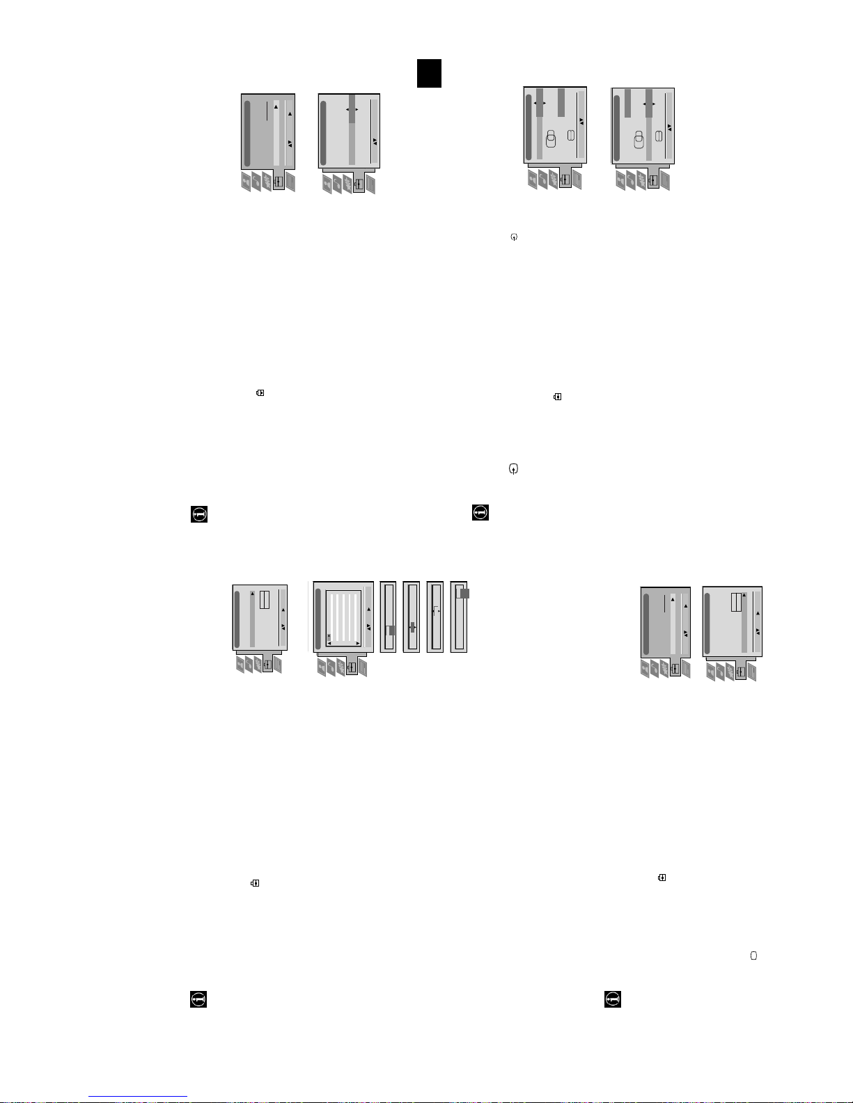
Using the TV menu system:
Because of the earth’s magnetism the picture might slant. In this case you can readjust the picture.
Adjusting the picture rotation
Set Up
RGB Set Up
Manual Programme Preset
Further Programme Preset
RGB Set Up
Picture Rotation
Personal ID
Demo
Rotate: Confirm: OK
Manual Set Up
Language/Country
Select: Enter :
Auto Tuning
Programme Sorting
Select Next View
AV Preset
Manual Set Up
H CentreOH Size
RGB Set Up
Adjust Position: Confirm: OK
H CentreOH Size
Adjust Size: Confirm: OK
1
‘Set Up’ menu
menu.
sub menu.
1. Press the MENU button on the remote control to display the menu on the TV screen.
2. Press the V button to select the symbol on the menu screen then press B to enter the
3. Press the V button to select ‘Manual Set Up’ then press B to enter the ‘Manual Set Up’
button to store.
4. Press the V button to select ‘Picture Rotatio n’ then press B to enter the ‘Picture Rotation’
5. Press the v or V buttons to rotate the picture over a range of -5 to +5 then press the OK
6. Press the MENU button to remove the menu from the TV screen.
When connecting an RGB source such as a Sony Playstation you may need to readjust the geometry of the picture.
Adjusting the picture geometry for an RGB source
1. Press the button on the remote control to select the connected RGB source .
Up’ menu
‘Manual Set Up’ menu
‘RGB Set Up’ sub menu.
of -10 to +10. Store the new range by pressing the OK button.
2. Press the MENU button to display the menu on the TV screen.
3. Press the V button to select the symbol on the menu screen then press B to enter the ‘Set
4. Press the V button to select ‘Manual Set Up’ on the menu screen then press B to enter the
5. Press the V button to select ‘RGB Set Up’ on the menu screen then press B to enter the
of -10 to +10. Store the new range by pressing the OK button.
6. Press B to select H Centre then press v or V to adjust the centre of the picture over a range
7. Press B to select H Size then press v or V to adjust the horizontal coordinates over a range
8. Press the MENU button to remove the menu from the TV screen.
Using the TV menu system:
With this feature you can a) adjust the attenuation of each channel, b) individually adjust the volume level of each channel,
Using the Further Programme Preset feature
Off
AV1
Press the v or V buttons to adjust the volume level (range -7 to +7) of the channel. Store by
PROG AFTVOL DECODER
On
1 -5
pressing the OK button. Repeat steps 5 and 6b if you wish to adju st the volume level of the
AV2
- - - - -
1 -5 On
PROG AFTVOL DECODER
other channels.
c) AFT - Automatic Fine Tuning
Press the v or V buttons to fine tune the channel frequency over a range of -15 to +15. Press
the OK button to confirm. Repeat steps 5 and 6c if you wish to fine tune other channels.
d)DECODER
Press the v or V buttons to select AV1 or AV2 for the programme position then press the OK
button to confirm. You can now attach a decoder to the AV1 or the AV2 socket on the back of
the TV and the picture from that decoder will appear on this programme number. Repeat steps
5 and 6d to preset the AV output for other programme positions.
7. Press the MENU button to remove the menu from the TV screen.
This function provides an overview of some of the features available on the TV.
Selecting the ‘Demo’ feature
1. Press the MENU button on the remote control to display the menu on the TV screen.
Set Up
Auto Tuning
Programme Sorting
Select: Enter:
Select Next View
AV Preset
Manual Set Up
‘Set Up’ menu
2. Press the V button to select the symbol on the menu screen then press B to enter the
O
Start
- - - - - - -
Manual Programme Preset
Further Programme Preset
4. Press the V button to select ‘Demo’ then press B to start the demonstration (which lasts for
RGB Set Up
Picture Rotation
Personal ID
Demo
approximately 5 minutes).
Select: Enter:
5. Press the button to remove the demonstration from the TV screen.
18
Manual Set Up
Language/Country
menu.
3. Press the V button to select ‘Manual Set Up’ then press B to enter the ‘Manual Set Up’
O
- - - - - - -
Manual Set Up
c) manually fine-tune the TV to obtain a better picture reception if the picture is distorted or d) preset the AV output for
the programme positions of channels with scrambled signals (eg from a pay TV decoder). In this way a connected VCR
records the unscrambled signal.
Select: Enter:
Language/Country
Manual Programme Preset
Further Programme Preset
RGB Set Up
Picture Rotation
Personal ID
Demo
Up’ menu
1. Press the MENU button on the remote control to display the menu on the TV screen.
2. Press the V button to select the symbol on the menu screen then press B to enter the ‘Set
3. Press the V button to select ‘Manual Set Up’ then press B to enter the ‘Manual Set Up’ menu.
4. Press the V button to select ‘Further Programme Preset’ then press B to enter the ‘Further
ATT
Further Programme Preset
PROG AFTVOL DECODER
Programme Preset’ menu.
Off
Off
Off
Off
Off
Off
Off
Off
OnOnOnOnOn
OnOnOn
000
000
000
Off
Off
Off
Off
Off
Off
Off
Off
1 2 3 4 5 6 7 8 91011
repeatedly to select a) ATT b) VOL c) AFT or d) DECODER. The selected item changes
5. Press the v or V buttons to select the relevant programme number then press the B button
Off
Off
Off
On
On
On
0
0
Off
Off
Off
Select: Enter:
colour.
PROG AFTVOLATT DECODER
Press the v or V buttons to switch attenuator ‘on’ or ‘off’. Press the OK button to confirm the
0
Off
On
1
1
PROG AFTVOL DECODER
selection. Repeat steps 5 and 6a if you wish to adjust the attenuation of the other channels.
b)VOL - Volume Offset
6. a)ATT - RF Attenuator
13
Troubleshooting
Additional Information
/
button on the remote control.
using the button on the fro nt of the TV.
Adjustment display. Adjust the brightness, picture and colour
balance levels.
to the factory settings.
remote control.
display and adjust the colour setting.
to the factory settings.
• Press the button on the front of the TV.
• If the indicator is on pre ss the button or a numbered
• Check the aerial connection.
• Turn the TV off for 3 or 4 seconds and then turn it on again
• Using the MENU system, select the Picture
• From the Picture Adjustment display select RESET to return
• Press the button on the remote control.
• If is displayed on the screen, press the button on the
Problem Suggested remedy
Here are some simple solutions to problems which may affect the picture and sound.
No picture (screen is dark), no sound • Plug the TV in.
Poor or no picture (screen is dark), but
good sound.
Good picture, no sound
No colour on colour programmes • Using the MENU system, select the Picture Adjustment
the rear of the TV.
• From the Picture Adjustment display select RESET to return
• Turn off any equipment connected to the scart connectors on
Distorted picture when changing
• Contact your nearest Sony service centre.
• Reduce sharpness level.
programmes or selecting Teletext
Remote control does not function • Replace the batteries.
The standby indicator on the TV
flashes
Interferance on picture from external
equipment
• If you continue to have these problems, have your TV serviced by qualified personnel.
• NEVER open the casing yourself.
24
23
2x10W (RMS)
15W (RMS)
Sound output
Left/Right: 2x20W (Music Power)
Sub woofer: 30W (M usic Power)
Power consumption
158W
Dimensions (wxhxd)
Approx. 765x635x570mm
Weight
Approx. 59kg
Accessories supplied
RM-893 remote control (1)
video input, RGB inpu t, TV audio/video output.
video input, S-video input, Monitor audio/ video output.
1
2
s
/ 21-pin Euro connector (CENELEC standard) including audio/
/ 21-pin Euro connector (CENELEC standard) including audio/
2
Specifications
Additional Information
TV system
B/G/H, D/K
Colour system
PAL, SECAM
NTSC 3.58, 4.43 (only Video In )
Channel coverage
See the ‘Channel Display Table’ below.
Picture tube
FD Trinitron, Approx. 72 cm (29 inches), 104° deflection.
Rear Terminals
1
IEC designated size AA batteries (2)
Other features
Flat display Trinitron tube, noise reduction, DRC 50Hz
picture, DRC 100Hz picture, P AP, PAT, M-PIP, graphic
equaliser, 2000 page TEXT memory, personal ID, sleep timer,
NexTView, Digital Comb Filter, second tuner.
Design and specifications are subject to change
without notice.
Receivable Channels Channel Displays
video input, S-video input, Monitor audio/ video output.
RCA connectors, variable output for audio signals
RF In
Video input -phono jacks
Audio inputs - phono jacks
S video input - 4 pin DIN
Headphones jack - minijack stereo
3
s
L/G/S/I
R/D/D/D
/ 21-pin Euro connector (CENELEC standard) including audio/
3
4
4
4
s
Front Terminals
Channel Display Table
B/G/H E2..12, 21..69 C02..C12, C21..69
M1..M10 S01..S10
U1..U10 S11..S20
CABLE TV (1) S1..S41 S01..S41
CABLE TV (2) S01..S05 S42..S46
S01..S05 S42..S46
ITALIA A..H, H1, H2 C13..C20
D/K R01..R12, R21..R69 C01..C12, C21..C69
14
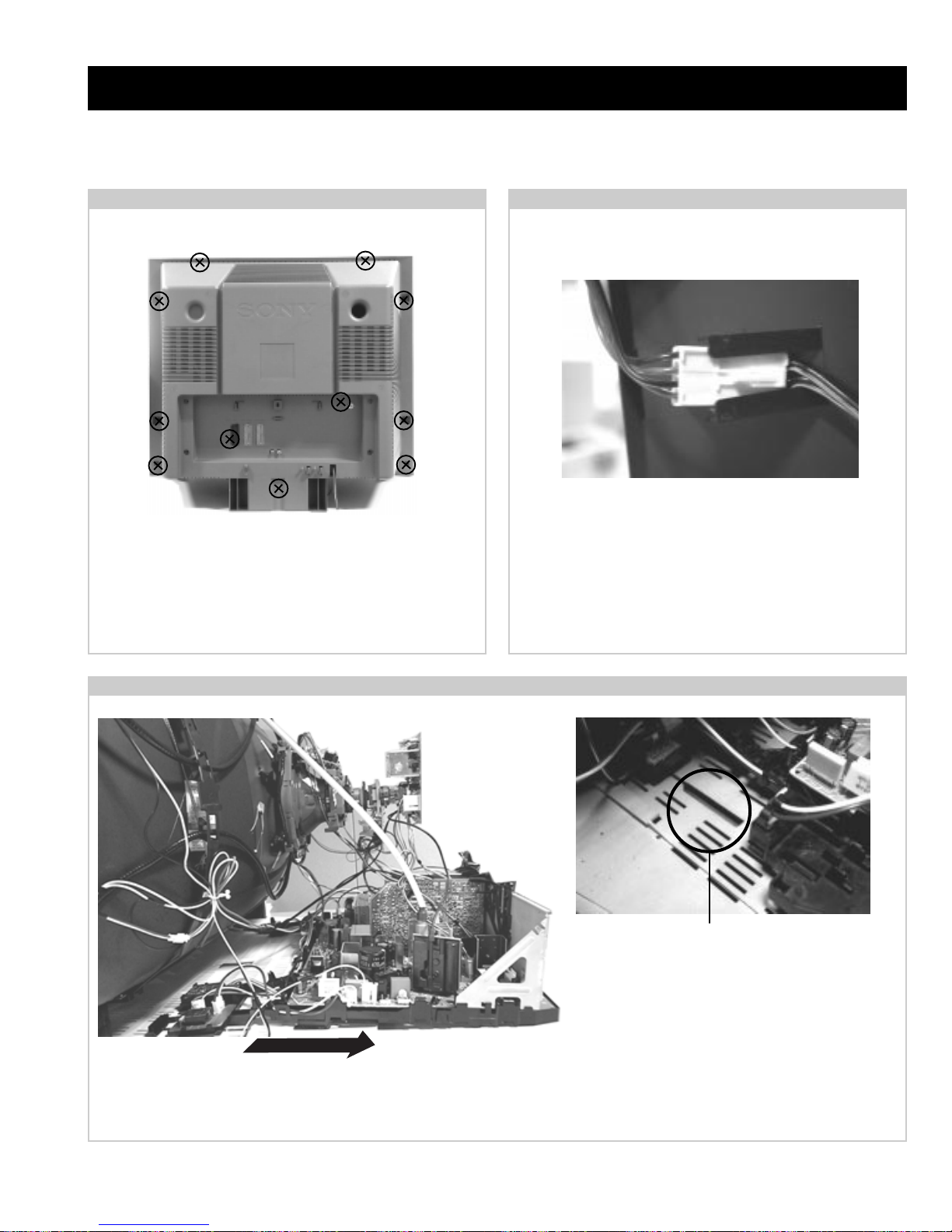
SECTION 2 DISASSEMBLY
2-1. Rear Cover Removal
Remove the rear cover fixing screws indicated. T ake care
when removing the rear cover not to damage the speaker
cables [Disconnect the speaker connector] as speakers are
fitted inside the rear cover.
2-2. Speaker Connector Disconnection
Before completely removing the rear cover disconnect the
speaker connector which is located on the inside.
2-3. Chassis Removal and Refitting
To remove lift the main bracket rear slightly and slide the
chassis away from the beznet. Ensure that the interconnecting
leads are released from their purse locks to prevent damage
being caused.
When refitting the chassis ensure that the main
bracket is located in the beznet guide slots before
sliding the chassis forwards. Refit the
interconnecting leads in their respective purse locks.
15
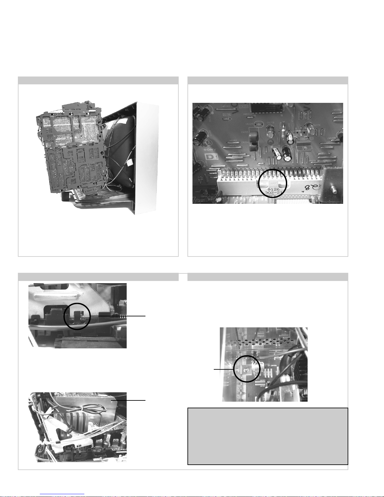
2-4. Service Position 2-5. D1 Board Removal
Position the PWB as indicated to access the solder side.
T o gain access to the D Board follow the instructions on page
19. [Removal and Replacement of the main bracket bottom
plates ].
2-6. J Board Removal
Clip
Release the two metal bracket support clips located on either
side of the chassis. Tilt the bracket very slightly away from the
shield case indicated. Release the J board board socket
retaining clip and carefully lift the complete assembly vertically.
Shield
case
To remove the D1 Board release the clip circled and gently
remove the board in a vertical direction.
2-7. B3 Board Removal
Follow the steps indicated in removal of the J board. With the
assembly removed access to the B3 board shield is possible. T o
remove the shield locate and remove the two screws positioned on
either side and at opposite ends of the shield. Release the B3 board clip
and remove in a vertical direction. Please ensure that the screws are
refitted after service.
Screw
Note :
Removal of the B3, E, and M1 printed circuit boards follows the
same procedure of releasing the securing clips as indicated
in the fig for D1 board removal.
Take care not to apply to great a pressure to the clips as this may
cause damage.
16
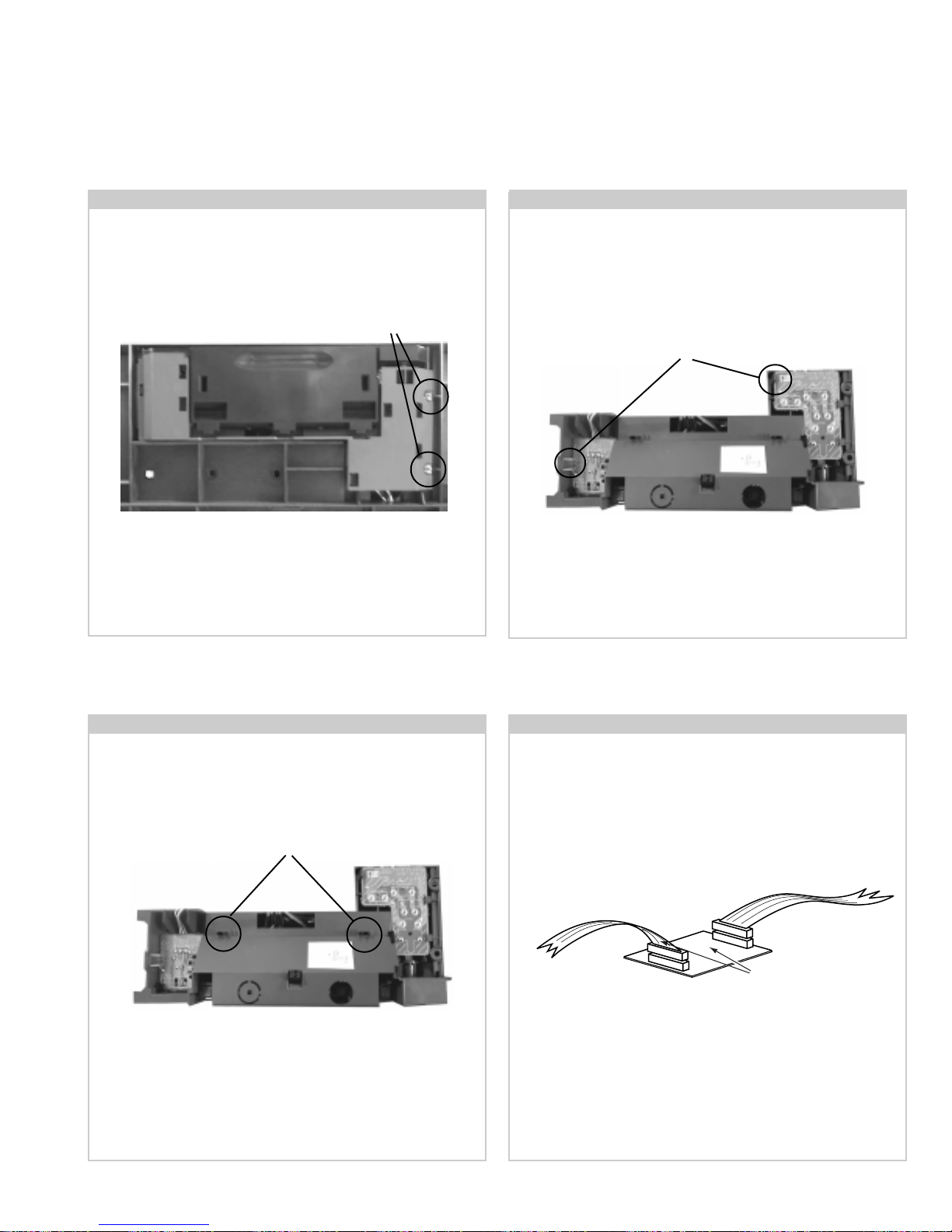
2-8. Front Control Module Removal 2-9. F3 and H6 Board Removal
Remove the two screws fixing the user control module to the
front underside of the set. The control module drops down to
T o remove the F3 and H6 Boards release the clips circled and
ease the boards gently away from the main support bracket.
allow access to the boards.
Screws
Clips
2-10. H5 Board Removal
To remove the H5 Board, first remove the control door from
bracket by releasing the clips circled and pushing them
through the main support bracket.
Clips
Removal of H5 Board follows the same procedure as removal
of the F3 and H6 Boards.
2-11. Service Connector for H5 Board
If there is a requirement to use the front video and audio
sockets when the chassis is placed in its service position, it
would be necessary to use an extender board and extension
cable as indicated below .
From H5 Board
To CN 1703 on
A Board
Extender board assembly A-1647-037-A
The Extender board and extension cable are available as a
service part by ordering the part number as indicated.
17
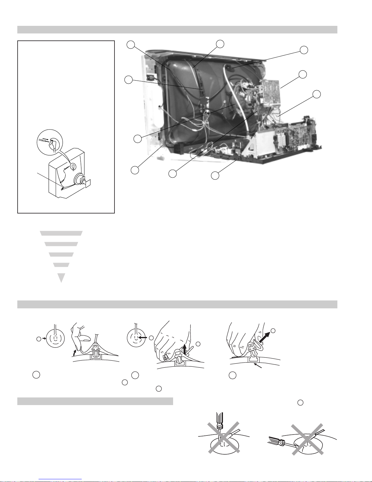
2-12. Picture Tube Removal
WARNING:
BEFORE REMOVING
THE ANODE CAP
High voltage remains in the CRT even
after the power is disconnected. To
avoid electric shock, discharge CRT
before attempting to remove the anode
cap. Short between anode and CRT
coated earth ground strap.
Coated Earth
Ground Strap
8
9
1
3
7
2
6
10
5
4
1. Discharge the anode of the CR T and remove the anode cap.
2. Unplug all interconnecting leads from the Deflection yoke, neck
assy, degaussing coils and CRT grounding strap.
3. Remove the C Board from the CR T .
4. Remove the chassis assembly .
5. Loosen the Neck assembly fixing screw and remove.
6. Loosen the Deflection yoke fixing screw and remove.
7. Place the set with the CRT face down on a cushion and remove
the Degaussing Coil holders.
8. Remove the Degaussing Coils.
9. Remove the CRT grounding strap and spring tentioners.
10. Unscrew the four CRT fixing screws [ located on each CR T
corner ] and remove the CRT .
[T ake care not to handle the CR T by the neck.]
Removal of the Anode-Cap
* REMOVING PROCEDURES.
a
1
Turn up one side of the rubber cap in
the direction indicated by the arrow a
2 Using a thumb pull up the rubber cap
firmly in the direction indicated by the
arrow b
How to handle the Anode-Cap
1. To prevent damaging the surface of the anode-cap do not use
sharp materials.
2. Do not apply too great a pressure on the rubber, as this may cause
damage to the anode connector.
3. A metal fitting called a shatter hook terminal is fitted inside the
rubber cap.
4. Do not turn the rubber foot over excessively, this may cause damage
if the shatter hook sticks out.
c
b
b
Anode button
3 When one side of the rubber cap is
separated from the anode button, the
anode-cap can be removed by turning
up the rubber cap and pulling it up in
the direction of the arrow c
18
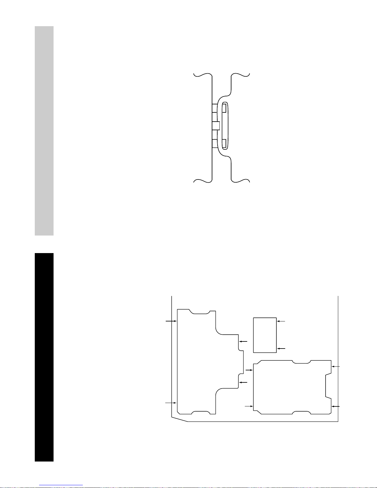
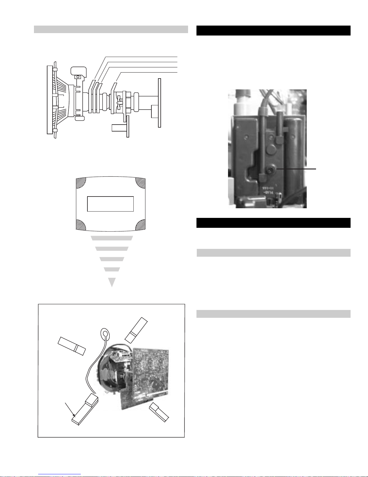
For safety reasons, on no account should the plates be
removed and not refitted after servicing.
£
Because the plates differ in size it is important that the correct plates are refitted in their original
location.
Please note that the plates need to be rotated 180 degrees from their cut position to allow the
(2) REFITTING THE PLATES
tabs to be fitted into their catch positions.
Catch
Tab
Only remove the necessary plate to gain access to the printed wiring board.
REMOV AL AND REPLACEMENT OF THE MAIN-BRACKET
BOTTOM PLA TES.
In the event of servicing being required to the solder side of the D Board printed wiring board,
the bottom plates fitted to the main chassis bracket require to be removed.
This is performed by cutting the gates with a sharp wire cutter at the locations indicated by the
arrows.
(1) REMOVING THE PLATES
Note : There are 3 plates fitted to the main bracket and secured by3 gates.
19
SECTION 3 SET-UP ADJUSTMENTS
• When complete readjustment is necessary or a new picture tube is
installed, carry out the following adjustments.
• Unless there are specific instructions to the contrary, carry out
these adjustments with the rated power supply.
• Unless there are specific instructions to the contrary, set the
controls and switches to the following settings :
Contrast .................................. normal
Brightness .................................. normal
3-1. Beam Landing
Preparation :
1. In order to reduce the influence of geomagnetism on the set’s
picture tube, face it in an easterly or westerly direction.
2. Switch on the TV set’s power and degauss with a degausser.
(1) Adjustment of Correction Magnet for Y-Splitting Axis.
1. Input a crosshatch signal from the pattern generator.
2. Set the Picture control to minimum and confirm that the
Brightness control is set to normal.
3. Position the neck assembly as indicated in Fig.3-2.
4. Loosen the deflection yoke fixing screw .
5. Move the deflection yoke as far forward as is possible.
6. Adjust the upper and lower pin symmetrically by opening or
closing the Y-splitting axis correction magnets located on the neck
assembly. [See Fig 3-3]
7. Return the deflection yoke to its original position and re-tighten its
fixing screw.
Fig.3-1
Y-splitting axis correction magnet
Carry out the adjustments in the following order :
3-1. Beam Landing.
3-2. Convergence.
3-3. Focus.
3-4. White Balance.
Note : T est equipment required.
1. Color bar/pattern generator .
2. Degausser .
3. Oscilloscope.
4. Digital multimeter.
(2) Landing
Note : Before carrying out the following adjustments adjust the
magnets as indicated below [See Fig.3-4].
1. Input a crosshatch signal from the signal generator.
2. Rough-adjust the focus and horizontal convergence.
3. Switch from the crosshatch pattern to an all-red pattern.
4. Move the deflection yoke backwards and adjust with the purity
magnet so that the red is at the centre and it aligns
symmetrically [See Fig.3-5].
5. Move the deflection yoke forward to the point where the entire
screen just becomes red [Mark its position].
6. Move the deflection yoke further forward until the screen just
changes colour at the edges. [Mark its position]
7. Position the deflection yoke between the two marks indicated
above.
8. Input a crosshatch pattern from the pattern generator and rotate the
deflection yoke so that the horizontal lines are parallel with the top
and bottom of the screen.
9. When the position of the deflection yoke has been determined,
fasten it with its fixing screw.
10. Switch the pattern generator to green then blue and confirm the
purity.
11. If the beam does not land correctly in all the corners of the screen,
use disk magnets to correct it. [Confirm the corner landing for
green and blue]
Fig.3-2
Neck assy
Caution :
High voltages are present on the Deflection yoke terminals - take care
when handling the Deflection yoke whilst carrying out adjustments.
20
Fig.3-3
G1
G2
+
G3
Align the edge
of the neck assy with
the edge of the G2 grid
on the G3 side.
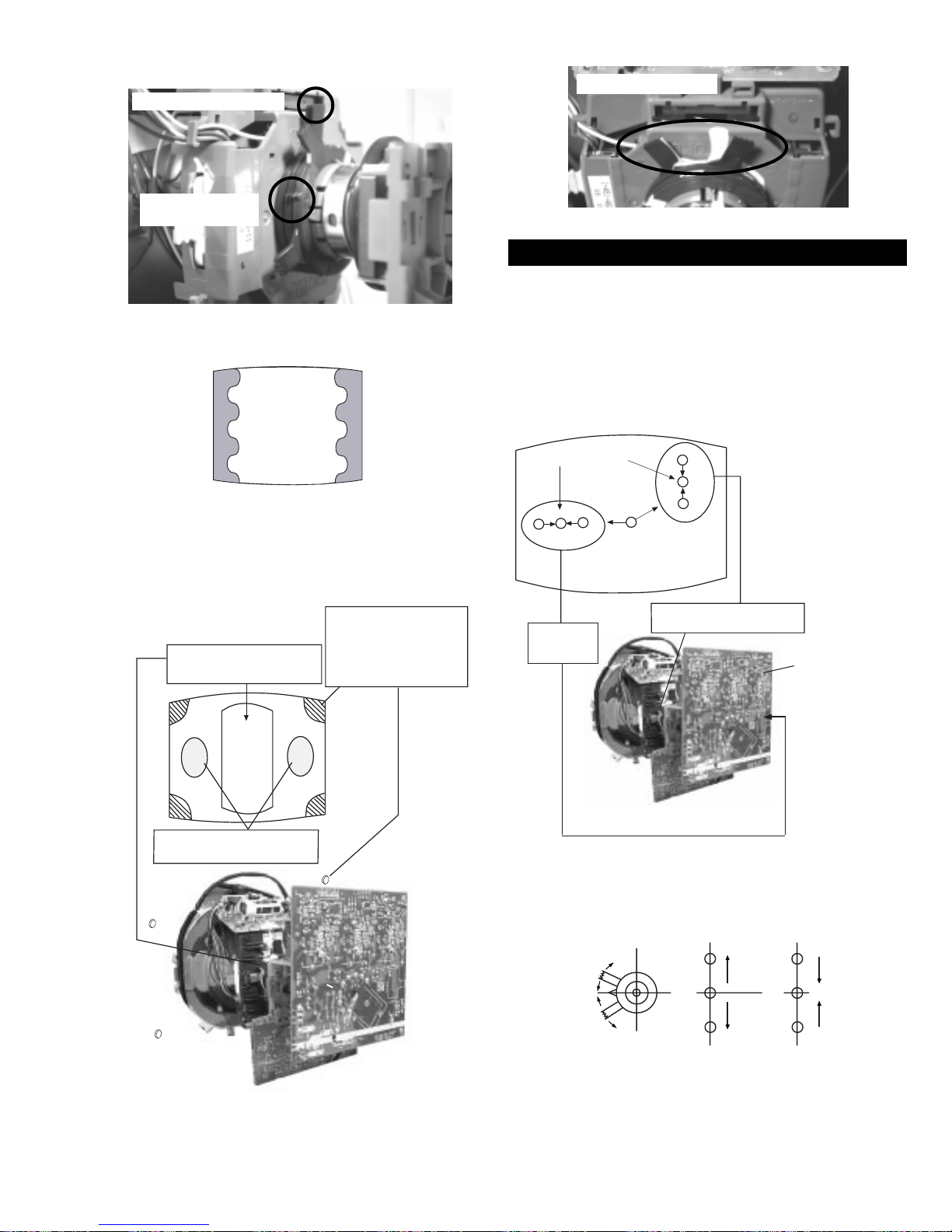
Fig.3-4
Purity magnets
Align pips on
each magnet
GREEN
RED
Align both Purity magnets
to the vertical position
BLUE
Purity control magnets
3-2. Convergence
(1) Screen centre convergence [Static convergence]
1. Input a dot pattern signal from the pattern generator.
2. Normalize the picture setting.
3. [Moving vertically], adjust the V.ST AT magnet so that the
vertical red, green and blue dots coincide at the centre of the
screen.
Center dot
R
G
B
Fig.3-5
Purity control corrects
this area
a
cd
b
Deflection yoke positioning
corrects these areas
Disk magnets or
rotatable disk
magnets correct
these areas (a-d)
R
G
B
H STAT
convergence
control
V.STAT Vertical Static Magnet
C Board
RV5375 (H STAT)
H STAT Convergence
(on mount side)
By opening or closing the V.ST AT magnet, the red green and blue
dots move in the direction indicated below.
B
B
Disk Magnets
G
R
Note: Do not adjust the H.STAT by rotating the V.STAT
magnets as this can affect the focus setting.
21
G
R
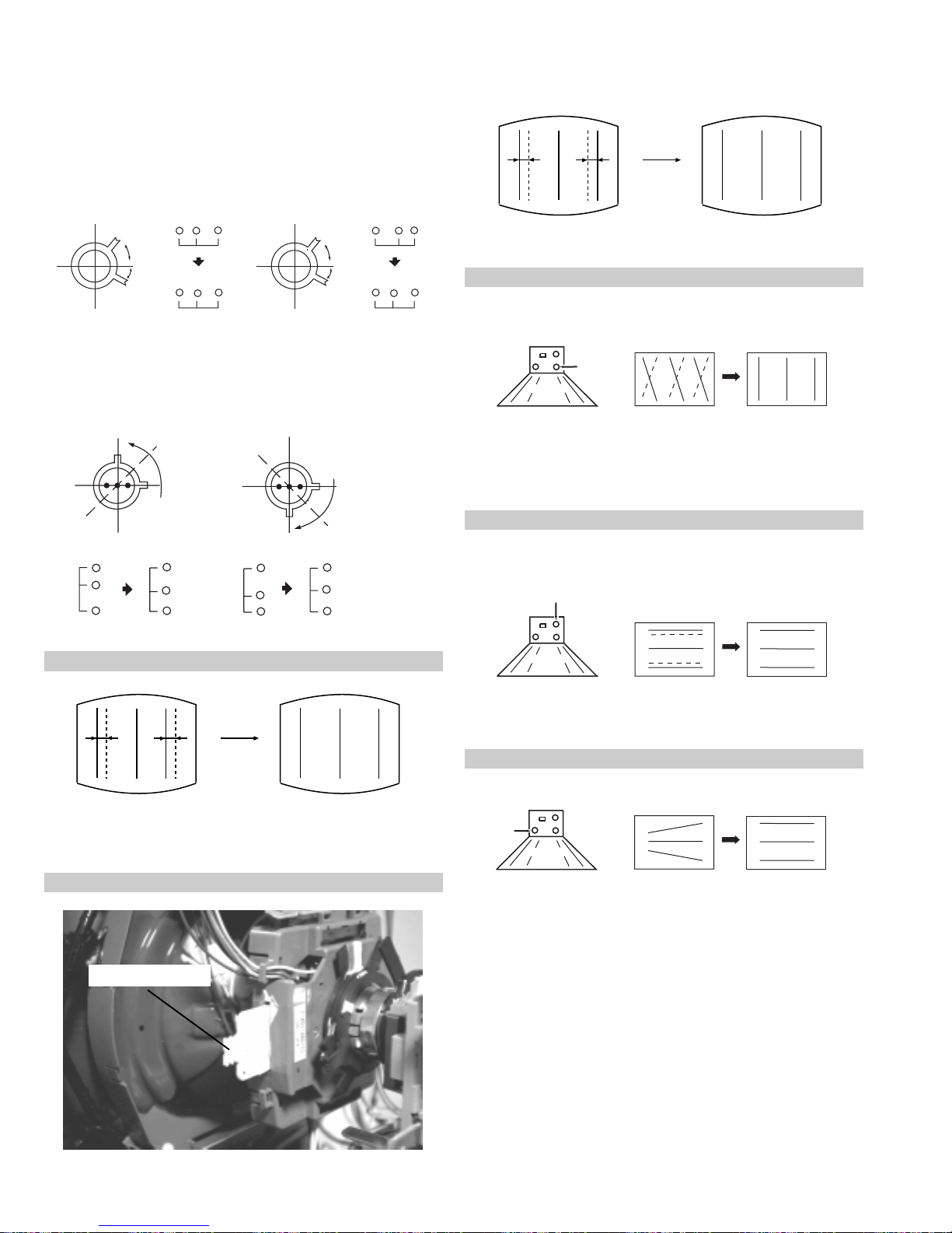
4. Correction for HMC [Horizontal mis-convergence] and VMC
[V ertical mis-convergence] by using the BMC [Hexapole] magnet.
a). HMC correction by BMC [Hexapole] magnet and movement of
the electron beam.
HMC correction(A) HMC correction(B)
A < B
RG B
A > B
RGB
HTIL correction can be performed by adding a THL correction
assembly to the Deflection yoke.
A = B
RG B
A = B
RG B
b). VMC correction by BMC [Hexapole] magnet and movement of
the electron beam.
VMC correction(A) VMC correction(B)
C < D
C
D
C = D C > D C = D
R
G
B
R
C
G
D
B
R
G
B
R
G
B
HAMP Adjustment
YCH Adjustment
+
+
+
YCH VR
Deflection Yoke
TLV Adjustment
TLV VR
+
+
+
Deflection Yoke
Adjust the HAMP using HAMPL and HAMPR registers in the
Dynamic Convergence section of the service menu.
HTIL Adjustment
THL Correction assy
H-TRAP Adjustment
+
+
HTRAP VR
+
Deflection Yoke
The H-TRAP should not be adjusted unless absolutely necessary as it
affects the TL V settings.
22
Layout of each control
Purity magnet
BMC (Hexaploe) magnet
V STAT convergence magnet
Y-splitting axis correction magnet
Note : If you are unable to adjust the corner convergence properly ,
this can be corrected with the use of permalloy magnets.
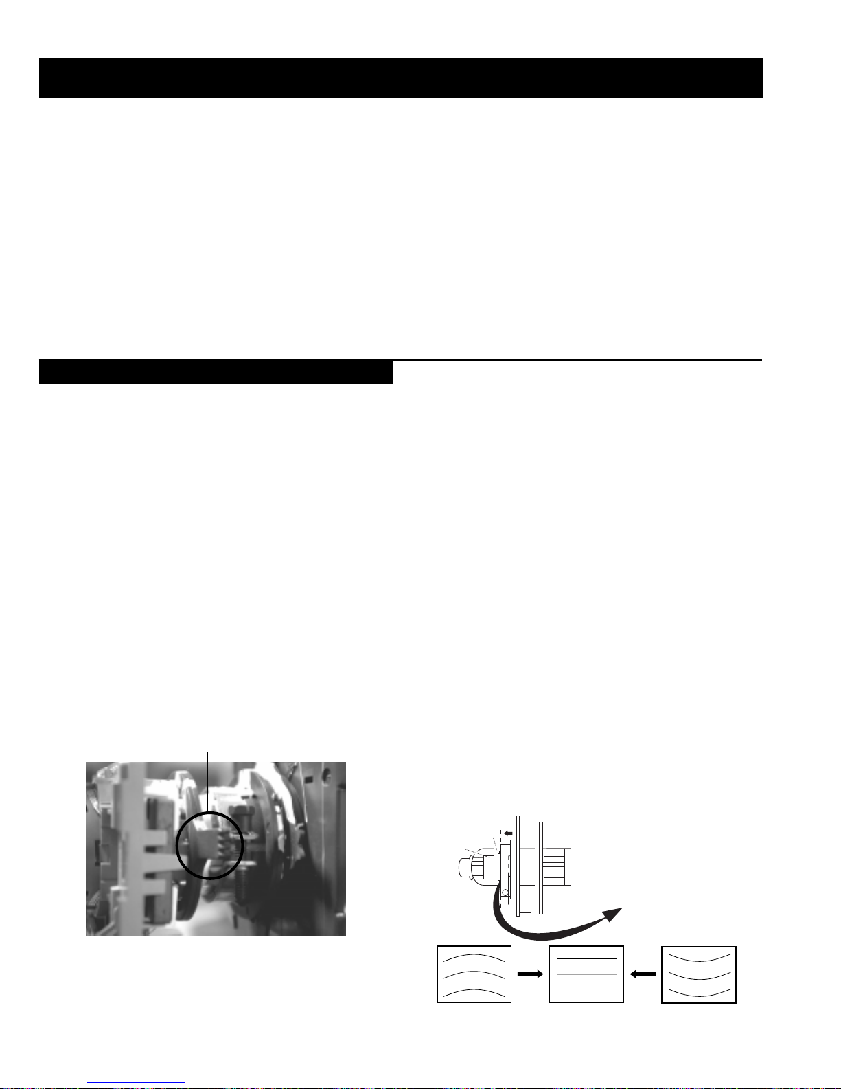
3-3. Focus Adjustment
1. Receive a television broadcast signal.
2. Normalize the picture setting.
3. Adjust the focus control located on the flyback transformer to
obtain the best focus at the centre of the screen.
Bring only the centre area of the screen into focus, the magentaring appears on the screen. In this case, adjust the focus to
optimize the screen uniformly.
Focus
Control
a
a-d: screen-corner
convergence defect
c
Install the permalloy assembly
for the area that needs correcting.
b
Permalloy Assy
X-4387-214-1
d
Convergence adjustment with permalloy
b
d
3-4. Screen (G2), White Balance
[Adjustment in the service mode using the remote
commander]
G2 adjustment [RV5376]
1. Input a dot signal from the pattern generator .
2. Set the Picture, Brightness and Colour to minimum.
3. Apply 170V DC from an external power supply to the R, G and B
cathodes of the CRT.
4. Whilst watching the picture, adjust the G2 control R V5376
[SCREEN] located on the C Board to the point just before the
flyback return lines disappear.
a
White balance adjustment for TV mode
1. Input an all-white signal from the pattern generator .
2. Enter into the ‘Service Mode’ by pressing ‘TEST’, ‘TEST’ and
‘MENU’ ‘MENU’ on the Service Commander.
3. Select ‘Backend’ from the on screen menu display and press
‘OK’.
4. The ‘Backend’ menu will appear on the screen.[See Page 26]
5. Set the ‘Contrast’ to MAX.
6. Set the ‘R-Drive’ to 41.
7. Adjust the ‘G-Drive’ and the ‘B-Drive’ so that the white
balance becomes optimum.
8. Press the ‘OK’ button to write the data for each item.
9. Set the ‘Contrast’ to MIN.
10. Set the ‘R-Cutoff’ to 31.
11. Adjust the ‘G-Cutoff’, and the ‘B-Cutoff’ with the left and
right buttons on the remote commander so that the white balance
c
becomes optimum.
12. Press the ‘OK’ button to write the data for each item.
23
SECTION 4 CIRCUIT ADJUSTMENTS
4-1. Electrical Adjustments
Service adjustments to this model can be performed using the supplied Remote Commander RM-893.
How to enter into the Service Mode
1. Turn on the main power switch of the set while pressing P + (plus) and P - (minus) buttons on the front drop down control panel.
++
s
4
L/G/S/I R/D/D/D
4
MONO
4
2. ‘TT’ will appear in the upper right corner of the screen.
3. Press the ‘MENU’ button twice on the remote commander to obtain the service menu on the screen.
P
__
RESET DEVICES
Backend
Deflection
Ext Deflection
Dynamic Convergence
Colour Decoder 1
Colour Decoder 2
Audio/Video Switch
Mid-X
External PLL Mid-X
Sound
Analog NR
SERVICE MENU
Initialising
Reset Devices
Monitoring
Device Register Setting
Special Adjustment
Select :
Next Menu
4. Push the joystick up or down on the remote commander to select the adjustment item.
5. Push the right button to proceed to the next menu.
6. If the required adjustment item is ‘Deflection’, push the down button to move to ‘Deflection’.
7. Push the joystick to the right to enter into ‘Deflection’.
8. Change the data in order to comply with each standard.
INITIALISING
Model Setting
Destination Setting
Basic Setting
Feature Setting
MONITORING
Device Status monitor
Error Monitor
Production Monitor
NVM Monitor
Format Monitor
CNI Monitor
Note :
• Before performing any adjustments ensure that the correct model has been selected in the ‘Model Setting’ menu.
• After carrying out the service adjustments, to prevent the customer accessing the ‘Service Menu’ switch the TV set OFF and then ON.
24

Initialising Menu
Basic Setting
gnisilaitinI
gnitteSledoM
gnitteSnoitanitseD
gnitteScisaB
gnitteSerutaeF
:tceleS:unemtxeN
Model Setting
The menu contains a list with all the available models of this software to
set up the TV set in an easy way . The selection of a model is setting data
for its features and hardware resources which cannot be detected by the
automatic power on H/W detection as well as a special model byte to get
an unique model identification for models which cannot be differed by
features and hardware resources (e.g. KV -28FC60 and
KV-28FC60Z)
Before data is set, the user will be asked if he really wants to set a new
model. If the user agrees, automatically the destination setting menu is
shown.
gnitteSledoM
eseR
106CF82-VK
2Z06CF82-VK
306CF92-VK
406CF23-VK
5Z06CF23-VK
606CF43-VK
757QF82-VK
8 57QF92-VK
957QF23-VK
0157QF43-VK
1107SF82-VK
2107SF23-VK
3107SF63-VK
KCALBytimrofnoCoN=
NEERGledoMelbitapmoC=
DERatadllarofytimrofnoC=
Table.4-1
Indication of Model Compatibility.
Black:
t
If any data does not match to specific model, the model name is
displayed in black.
Green:
All data which is checked by model setting menu concurs to model
except model byte.
Red:
All data which is checked by model setting menu concurs to model
including model byte.
Note:
After selecting a model, it may be necessary to reset some devices to get
the correct data. (Treble/Bass Offset of Sound, deflection adjustments,
...)
gnittescisaB
oNrcseDniMxaMataD
1G/B.sySFFONONO
2K/D.sySFFONONO
3L.sySFFONOFFO
4)KU(I.sySFFONOFFO
5)LRI(I.sySFFONONO
6noitpo.taNTXT143
7TRC9:61FFONOFFO
8refoow-buSFFONONO
9yb-dnatsotuAFFONONO
01retlif-bmoCFFONONO
11tedCYotuAFFONONO
21tedbmocotuAFFONONO
31elbaliavA2VAFFONONO
41elbaliavA3VAFFONONO
51elbaliavA4VAFFONONO
61raer&rF3VAFFONOFFO
71epaTMACESFFONOFFO
81etuMdnuoS1VAFFONOFFO
Table.4-2
Feature Setting
gnitteserutaeF
oNrcseDniMxaMataD
1PAPFFONONO
2TAPFFONONO
3XEDNIFFONONO
4GPEFFONONO
5GPELLUFFFONONO
Table.4-3
Device Register Setting
dnekcaB
noitcelfeD
noitcelfeDtxE
ecnegrevnoCcimanyD
1redoceDruoloC
2redoceDruoloC
hctiwSoediV/oiduA
X-diM
X-diMLLPlanretxE
dnuoS
RNgolanA
Table.4-4
25

hctiwSoediV/oiduA
dnekcaB
oNrcseDfeDniMxaMataD
11TUOVC0090
22TUOVC2092
3WS1DGFFOFFONONO
4WS2DGFFOFFONONO
51TUOCY0070
62TUOCY1071
7LRTC0OLFFOFFONOFFO
8LRTC1OLFFOFFONOFFO
91TUOA3073
012TUOA3073
11ETUM3TUOAFFOFFONOFFO
21WSDCZNOFFONONO
313TUOA3073
41LEDPUORG5101351
51R/L3TUOA0030
61FLOV3TUOA0070
71CLOV3TUOA3073
811CNYS1011
912CNYS1011
Table.4-5
tnemtsujdAlaicepS
oNrcseDniMxaMataD
1levelBGR070
2niaGBGR0138
3leveLtaPBGR070
4niagtaPBGR01351
5noitisoP-HBGR01-01+0
6wFartxE0552552
7kcehCskhCGPEFFONONO
8hgiHrecilSFFONONO
9ediWWCFFFONONO
01RNgepMFFONOFFO
11retliFhctoNFFONOFFO
21petSDLN7-0131petSDKP51-0541petSDRC0517
51petSPHS01-0361petSLOC01-0171petSniagPHS5-00
81petSlevelMV3-00
912VACYotuACSTNFFONOFFO
023VACYotuACSTNFFONOFFO
12DGnretnIFFONONO
Table.4-6
oNrcseDfeDniMxaMataD
1no-RNOFFONONO
2no-GNOFFONONO
3no-BNOFFONONO
4loc-DFFOFFONOFFO
5sixa-roloC2032
6tsartnoC0403604
7vuL-timiL3033
8euH1303613
9ruoloC1303682
01leveL-ITC2032
11ssenthgirB1303613
21ammaG2032
31ssenprahS0303682
41evirD-R1403614
51evirD-G1403673
61evirD-B1403662
71edoM-LBA0032
81thgirBbuS1303631
91leveL-MV2031
02ffotuC-R1303613
12revoerP2032
22ffotuC-G1303614
32leveL-CIPD1032
42ffotuC-B1303674
52narT-CD0031
62tnoC-buS70517
72lvL-2BGRL80518
82lbA-P5105151
92oF.prahSNOFFONONO
03W-gnigAFFOFFONOFFO
13B-gnigAFFOFFONOFFO
231tesffo-BC1105111
331tesffo-RC1105111
432tesffo-BC70517
532tesffo-RC70517
63roloCbuS08-80
Table.4-7
oNrcseDfeDniMxaMataD
1tniT1303613
2wGN/PFFOFFONOFFO
3DIN/PFFOFFONOFFO
4ruoloCbuS70517
5rtnoCbuS80518
6OFprahS1031
7QEprahS2032
8niaGprahS80518
9veLtuO-Y5303653
01tnioPSB0030
11veLtuO-C5403654
21tseRCD0030
31OFFPB2032
41QFPB1031
51wSretliFFFOFFONOFFO
Table.4-8
1redoceDruoloC
26

)tnoc(1redoceDruoloC
dnuoS
oNrcseDfeDniMxaMataD
1leveL.feR0400204
2niag-otuANOFFONONO
3ni-anA0010
4etum-rraCNOFFONONO
5tuokcolCNOFFONONO
6niag-MANOFFONONO
7edompilC 0020
8loV1TRACS970 72197
9loV2TRACS970 72197
01rPTRACS720 72172
11rp-1S2I610 72161
21rp-2S2I610 72161
31rpMF720 72172
41rp-ciNGB350 72135
51rp-ciNL950 72195
61rp-ciNKD350 72135
71rp-ciNI790 72179
81rp-ciNlrI790 72179
91yaceD-CVA2082
02lov-WbuS0721-0412qerf-WbuS0250402
22ssaPH-WbuSFFOFFONOFFO
32erts-tapS721+01-721
42ffeoC-tapS0080
52sffossaB03-3+0
62sffoelberT2-3-3+172sffonduoL0090
82sffoloV-pH2-5-5+292timiLS-M03+821-721+03
03timiLB-M03-821-721+0313timiLM-S21+821-721+21
23timiLB-S02-821-721+0233timiLM-B21-821-721+2143timiLS-B02+821-721+02
53xaM.rrE040 55204
63niM.rrE810 55281
73sffO.loV06-04-
noitcelfeD.txE
oNrcseDfeDniMxaMataD
1ytiraeniL7210552721
2ertneCH1303613
3parTH1303613
4noitatoR005520
5esahPsucoF7210552721
oNrcseDfeDniMxaMataD
61wSparT-C0010
71parTD-SNOFFONONO
81FPLNOFFONONO
91LD-Y80018
02bmoC-NNOFFONONO
12leSoediV00510
22leSBGR0030
32enotflaHFFOFFONOFFO
421.FFOrC70517
521.FFObC70517
622.FFOrC70517
722.FFObC70517
82qerFDCV3073
92edoMDCV0030
03SNESCFA1031
13MVMFFOFFONOFFO
23jdAY-R-S60514
33jdAY-B-S40516
43FPH/LLEB2032
53OFLLEBFFOFFONOFFO
63PG-S0030
73DISFFOFFONOFFO
83BNE1BGRFFOFFONOFFO
93HP-SH1010
04WSotuA1011
14HP_PV0010
24OITARN/S3033
Table.4-9
oNrcseDfeDniMxaMataD
1egnaR3603636
2tatSV6303671
3tatSH3303613
4LpmaH7303633
5RpmaH6303633
6YpU1303613
7YwoL3303613
8LpuY0303654
9RpuY0303613
01LwolY1303613
11RwolY0303654
21LpUwobM1303613
31RpUwobM2303613
41LwoLwobM2303613
51RwoLwobM2303613
61lrtCProCTFFOFFONOFFO
71niProCpoT1303613
81lrtCProCBFFOFFONOFFO
91niProCtoB3403613
Table.4-10
ecnegrevnoCcimanyD
Table.4-11
Table.4-12
27
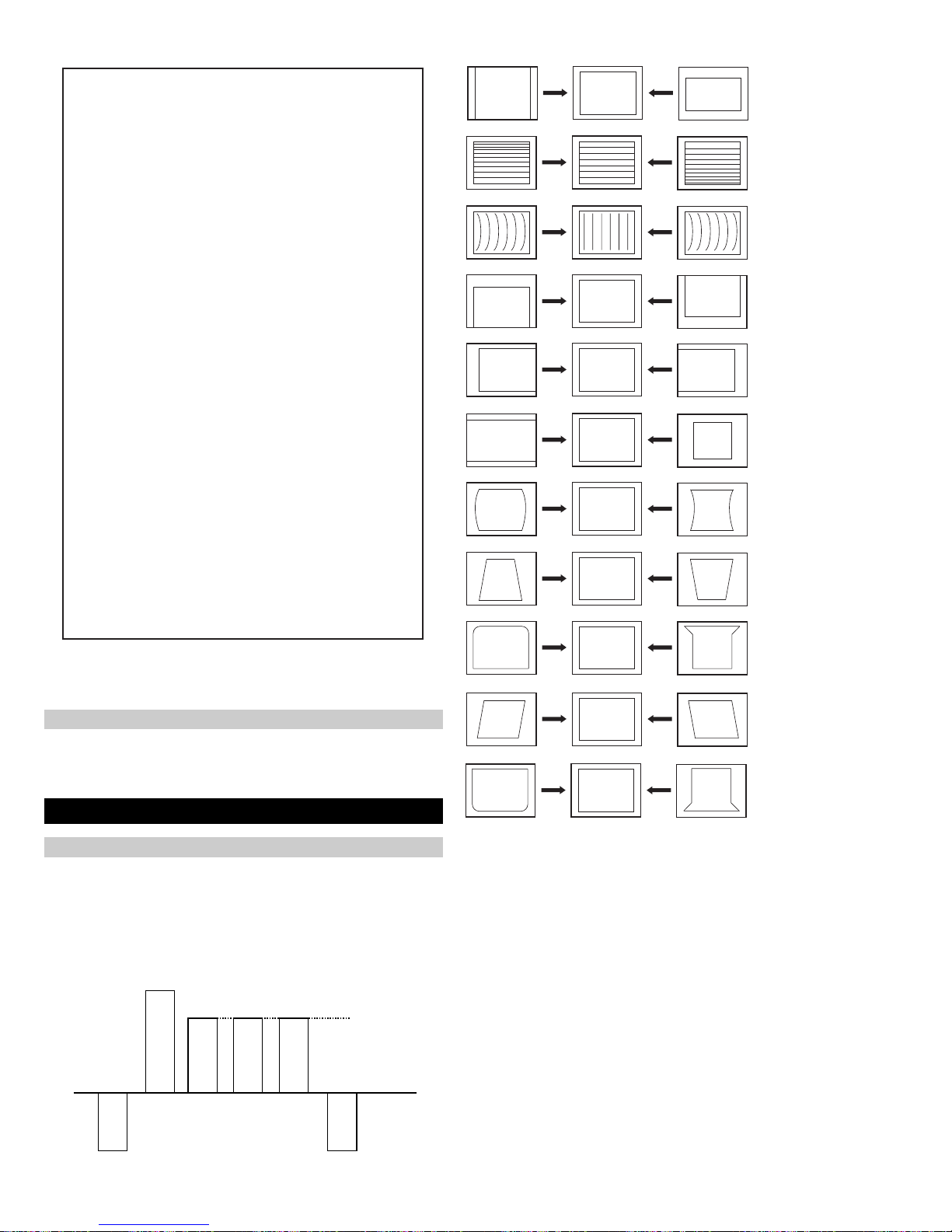
noitcelfeD
oNrcseDfeDniMxaMataD
1eziS-V1303613
2noitisoP-V1303603
3pmoC-V1031
4raeniL-V70517
5rroC-S70517
6eziS-H1303623
7CD-WEFFOFFONOFFO
82miTbkAFFOFFONOFFO
9pmA-niP1303692
01pmoC-H0030
11nipC-pU1303623
21niP-M2032
31niPC-oL1303643
41muizeparT70516
51noitisoP-H1303613
61wKlbV0030
71woB-CFA70517
81elgnA-CFA70518
91klB-tfeL8303683
02klB-thgiR2103621
12nureerF-V0030
22tcepsA-V7403674
32wS-mooZFFOFFONOFFO
42nacS-UFFOFFONOFFO
52llorcS-V4303643
62miT-bkA2032
72nilV-pU00510
82nilV-oL00510
Table.4-13
V SIZE
V LIN
AFC V BOW
V POS
H POS
H SIZE
H PIN CUSH
H TIL T
H UP COR
Deflection System Adjustment
1. Enter into the service mode and select ‘Deflection’ from the
menu. The ‘Deflection’ adjustment menu will be displayed.
2. Select and adjust each item to obtain the optimum image.
4-2. V olume Electrical Adjustments
Sub Colour Adjustment
1. Input a PAL colour bar signal.
2. Connect an oscilloscope to CN5400 pin 5 located on the C Board.
3. Enter into the ‘Service Mode’.
4. Choose ‘Backend’ from the menu.
5. Adjust ‘Sub Colour’ data so that the right sides of the waveform
are of equal height.
Same Level
B-Out Wav ef orm
AFC V ANGLE
H LOWER COR
28

4-3. TEST MODE 2:
Is available by pressing the ‘TEST’ button twice, OSD ‘TT’ appears. The functions described below are available by selecting the two numbers. To
release the ‘T est mode 2’, press 0, 10, 20 ... twice or switch the TV set into Stand-by mode. Pressing the two Local Control buttons (+ and -) during
power ON will also switch into ‘TT’ mode.
In ‘TT’ mode, it is possible to remove the Menu from the screen by pressing the Speaker Off button once. Pressing the Speaker OFF button a
second time will cause the Menu to reappear. The function is kept even when the menu is not displayed on screen !!.
00
10
20
30
40
50
60
70
80
01
11
21
31
41
51
61
71
81
91
02
12
22
32
42
52
62
72
82
03
13
23
33
43
53
63
73
83
93
04
14
24
34
44
54
64
74
84
94
05
15
25
35
ffoedom'TT'
mumixamerutciP
muminimerutciP
%03otemuloVenohpdaeh/rekaepsteS
%05otemuloVenohpdaeh/rekaepsteS
%56otemuloVenohpdaeh/rekaepsteS
%08otemuloVenohpdaeh/rekaepsteS
edomgniegA
noitidnoCgnippihS
noitcnufoN
tnemtsujdaerutcipbuS
tnemtsujdaruolocbuS
noitaregifnoctesVTdnanoisreverawtfosyalpsiD
yalpsiDofnInoitcudorP
noitatoRerutciP
%05levelerutciP
noetumoiduA
noitcnufoN
tnemtsujdassenthgirbbuS
noitcnufoN
sutatsVTyalpsid,sgnittestxetsedulcniAnoitanitseD
sutatsVTyalpsid,sgnittestxetsedulcniLnoitanitseD
sutatsVTyalpsid,sgnittestxetsedulcniEnoitanitseD
sutatsVTyalpsid,sgnittestxetsedulcniUnoitanitseD
sutatsVTyalpsid,sgnittestxetsedulcniDnoitanitseD
sutatsVTyalpsid,sgnittestxetsedulcniBnoitanitseD
sutatsVTyalpsid,sgnittestxetsedulcniKnoitanitseD
sutatsVTyalpsid,sgnittestxetsedulcniRnoitanitseD
noitcnufoN
1tnemtsujdAyrtemoeG
2tnemtsujdAyrtemoeG
rotinomrorrE
noitcnufoN
sutatsVTyalpsiD;9:61><3:4TRC
hctiwsnoitceted32eniL
tset)MV(noitaludoMyticoleV
noitcnufoN
noitcnufoN
noitcnufoN
kcehcedomneercS
yrtemoegesilaitini-eR
noitcnufoN
noitcnufoN
noitcnufoN
rednammocrelaedrofdevreseR
MVNesilaitini-eR
nigrivnonsaMVNteS
nigrivsaMVNteS
noitcnufoN
%09otemulovybloDteS
ylnorekaepstfelnoybloD
ylnorekaepsthgirnoybloD
45
55
06
16
26
36
46
56
86
96
07
17
27
37
47
57
67
77
87
97
08
18
28
38
68
78
88
98
09
19
29
39
49
59
69
79
89
99
noitcnufoN
edomecivreS
MVNfonoitacol
nororreerongI
noitcnufoN
noitcnufoN
noitcnufoN
noitcnufoN
.tnemtsujda
.snottub
.tnemtsujda
noitcnufoN
noitcnufoN
noitcaoN
noitcaoN
ylnoertnectfelnoybloD
ylnorekaepsdnuorrusnoybloD
edomnoitcudorP
erutcipehtotniMORmorfatadtesererutcipehtypoC
MVNfonoitacolteser
teserotMVNmorfataderutcipjdalautcaehtypoC
sedocrorreteseR
ffosrorreerongI
lanretxednapihcAMARONAPfosetadtluafedypoC
MVNotniMORmorfLLP
slebalnoitatslladna5-1tpecxesemmargorpllaraelC
,DIMrofniPrenroCreppU/pmANIProftnemtsujdA
edom10521dnaGPE
,DIMrofdiozeparT/niPrenroCrewoLroftnemtsujdA
edom10521dnaGPE
edom10521rofniPMroftnemtsujdA
kcehcretsooBerutciP
gniknalboedivoN
,edomPAPnierutciptfelroftnemtsujdalatnoziroH
XEDNInierutcipertnecdnaedomTAPnierutciptxet
kcitsyojthgirdnatfelhtiwenodsitnemtsujdA.edom
.snottub"KO"ro"VT"ybdesaeler,nottub
erofebtesebtsumedomgnidnopserrocehT
edomPAPnierutcipthgirroftnemtsujdalatnoziroH
htiwenodsitnemtsujdA.edomTAPnierutcipevildna
"KO"ro"VT"ybdesaeler,nottubkcitsyojthgirdnatfel
erofebtesebtsumedomgnidnopserrocehT
teserDIlanosreP
ffokcoLlatneraP
ffo/noetumDSO
htiw)noitcelfeD.txE/esahPsucoF(tnemtsujdasucoF
.nottubkcitsyojthgirdnatfel
tfelhtiw)noitcelfeD.txE/leveLCD(tnemtsujdasucoF
.nottubkcitsyojthgirdna
ylnopuorgerawtfosrofdevreseR
00roKOybdesaeler,dnammoctsetedomXEDNI
lennahcdnuorrusniNOretliFssaPwoLybloD
lennahcdnuorrusniFFOretliFssaPwoLybloD
00roKOybdesaeler,kcehcrekaepS
29

Memo
30
 Loading...