

Page 1

DIGITAL MOTION PICTURE CAMERA
F65
OPERATION MANUAL [English]
1st Edition
Page 2

Before operating the unit, please read this manual thoroughly
and retain it for future reference.
WARNING
To reduce the risk of fire or electric shock,
do not expose this apparatus to rain or
moisture.
To avoid electrical shock, do not open the
cabinet. Refer servicing to qualified
personnel only.
Egenskaper för intern lasermodul
Våglängd : 850 nm
Strålningens varaktighet : Pulsmodulation
Lasereffekt : 4 mW/kanal (max)
Standard : IEC60825-1 (2007)
Egenskaper for innvendig lasermodul
Bølgelengde : 850 nm
Strålingsvarighet : Pulsmodulasjon
Utgangseffekt for laser : 4 mW / kanal (maks.)
Standard : IEC60825-1 (2007)
Caution
The use of optical instruments with this product will increase
eye hazard.
Caution
Use of controls or adjustments or performance of procedures
other than those specified herein may result in hazardous
radiation exposure. Do not open the outer case and
disassemble or otherwise modify.
This Digital Motion Picture Camera is classified as a CLASS 1
LASER PRODUCT.
Tämä Digital Motion Picture Camera on luokiteltu 1. LUOKAN
LASERTUOTTEEKSI.
Den här Digital Motion Picture Camera klassificeras som en
LASERPRODUKT AV KLASS 1.
VAROITUS!
LAITTEEN KÄYTTÄMINEN MUULLA KUIN TÄSSÄ
KÄYTTÖOHJEESSA MAINITULLA TAVALLA SAATTAA
ALTISTAA KÄYTTÄJÄN TURVALLISUUSLUOKAN 1
YLITTÄVÄLLE NÄKYMÄTTÖMÄLLE LASERSÄTEILYLLE.
For the customers in the U.S.A.
This equipment has been tested and found to comply with the
limits for a Class A digital device, pursuant to Part 15 of the
FCC Rules. These limits are designed to provide reasonable
protection against harmful interference when the equipment is
operated in a commercial environment. This equipment
generates, uses, and can radiate radio frequency energy and,
if not installed and used in accordance with the instruction
manual, may cause harmful interference to radio
communications. Operation of this equipment in a residential
area is likely to cause harmful interference in which case the
user will be required to correct the interference at his own
expense.
You are cautioned that any changes or modifications not
expressly approved in this manual could void your authority to
operate this equipment.
All interface cables used to connect peripherals must be
shielded in order to comply with the limits for a digital device
pursuant to Subpart B of Part 15 of FCC Rules.
This device complies with Part 15 of the FCC Rules. Operation
is subject to the following two conditions: (1) this device may
not cause harmful interference, and (2) this device must
accept any interference received, including interference that
may cause undesired operation.
VARNING
OM APPARATEN ANVÄNDS PÅ ANNAT SÄTT ÄN I DENNA
BRUKSANVISNING SPECIFICERATS, KAN ANVÄNDAREN
UTSÄTTAS FÖR OSYNLIG LASERSTRÅLNING, SOM
ÖVERSKRIDER GRÄNSEN FÖR LASERKLASS 1.
Internal Laser Module Properties
Wavelength : 850 nm
Emission duration : Pulse Modulation
Laser output power : 4 mW/channel (max)
Standard : IEC60825-1 (2007)
Egenskaber for internt lasermodul
Bølgelængde : 850 nm
Strålingsvarighed : Pulsmodulering
Afgivet lasereffekt : 4 mW/kanal (maks.)
Standard : IEC60825-1 (2007)
2
For the customers in Canada
This Class A digital apparatus complies with Canadian ICES-
003.
For the customers in Europe
This product with the CE marking complies with the EMC
Directive issued by the Commission of the European
Community.
Compliance with this directive implies conformity to the
following European standards:
• EN55103-1: Electromagnetic Interference(Emission)
• EN55103-2: Electromagnetic Susceptibility(Immunity)
This product is intended for use in the following
Electromagnetic Environments: E1 (residential), E2
(commercial and light industrial), E3 (urban outdoors), E4
(controlled EMC environment, ex. TV studio).
The manufacturer of this product is Sony Corporation, 1-7-1
Konan, Minato-ku, Tokyo, 108-0075 Japan.
Page 3
The Authorized Representative for EMC and product safety is
Sony Deutschland GmbH, Hedelfinger Strasse 61, 70327
Stuttgart, Germany. For any service or guarantee matters
please refer to the addresses given in separate service or
guarantee documents.
For the State of California, USA only
Perchlorate Material - special handling may apply, See
www.dtsc.ca.gov/hazardouswaste/perchlorate
Perchlorate Material : Lithium battery contains perchlorate.
For the customers in Taiwan only
AVERTISSEMENT
Afin de réduire les risques d’incendie ou
d’électrocution, ne pas exposer cet
appareil à la pluie ou à l’humidité.
Afin d’écarter tout risque d’électrocution,
garder le coffret fermé. Ne confier
l’entretien de l’appareil qu’à un personnel
qualifié.
Digital Motion Picture Camera est classée comme PRODUIT
LASER DE CLASSE 1.
Propriétés du module laser interne
Longueur d’onde : 850 nm
Durée d’émission : Modulation d’impulsion
Puissance du laser : 4 mW/canal (max)
Norme : IEC60825-1 (2007)
Pour les clients au Canada
Cet appareil numérique de la classe A est conforme à la
norme NMB-003 du Canada.
Pour les clients en Europe
Ce produit portant la marque CE est conforme à la Directive
sur la compatibilité électromagnétique (EMC) émise par la
Commission de la Communauté européenne.
La conformité à cette directive implique la conformité aux
normes européennes suivantes :
• EN55103-1 : Interférences électromagnétiques (émission)
• EN55103-2 : Sensibilité électromagnétique (immunité)
Ce produit est prévu pour être utilisé dans les environnements
électromagnétiques suivants : E1 (résidentiel), E2
(commercial et industrie légère), E3 (urbain extérieur) et E4
(environnement EMC contrôlé, ex. studio de télévision).
Le fabricant de ce produit est Sony Corporation, 1-7-1 Konan,
Minato-ku, Tokyo, 108-0075 Japon.
Le représentant autorisé pour EMC et la sécurité des produits
est Sony Deutschland GmbH, Hedelfinger Strasse 61, 70327
Stuttgart, Allemagne. Pour toute question concernant le
service ou la garantie, veuillez consulter les adresses
indiquées dans les documents de service ou de garantie
séparés.
3
Page 4

WARNUNG
Um die Gefahr von Bränden oder
elektrischen Schlägen zu verringern, darf
dieses Gerät nicht Regen oder Feuchtigkeit
ausgesetzt werden.
Um einen elektrischen Schlag zu
vermeiden, darf das Gehäuse nicht
geöffnet werden. Überlassen Sie
Wartungsarbeiten stets nur qualifiziertem
Fachpersonal.
Dieser Digital Motion Picture Camera ist als
LASERPRODUKT DER KLASSE 1 eingestuft.
Eigenschaften des internen Lasermoduls
Wellenlänge : 850 nm
Emissionsdauer : Pulsmodulation
Laser-Ausgangsleistung : 4 mW/Kanal (max.)
Standard : IEC60825-1 (2007)
Für Kunden in Europa
Dieses Produkt besitzt die CE-Kennzeichnung und erfüllt die
EMV-Richtlinie der EG-Kommission.
Angewandte Normen:
• EN55103-1: Elektromagnetische Verträglichkeit
(Störaussendung)
• EN55103-2: Elektromagnetische Verträglichkeit
(Störfestigkeit)
Für die folgenden elektromagnetischen Umgebungen: E1
(Wohnbereich), E2 (kommerzieller und in beschränktem
Maße industrieller Bereich), E3 (Stadtbereich im Freien) und
E4 (kontrollierter EMV-Bereich, z.B. Fernsehstudio).
Der Hersteller dieses Produkts ist Sony Corporation, 1-7-1
Konan, Minato-ku, Tokyo, 108-0075 Japan.
Der autorisierte Repräsentant für EMV und Produktsicherheit
ist Sony Deutschland GmbH, Hedelfinger Strasse 61, 70327
Stuttgart, Deutschland. Bei jeglichen Angelegenheiten in
Bezug auf Kundendienst oder Garantie wenden Sie sich bitte
an die in den separaten Kundendienst- oder
Garantiedokumenten aufgeführten Anschriften.
4
Page 5

Table of Contents
Chapter 1 Overview
1-1 Features ...........................................................................7
1-2 Example of System Configuration ................................9
1-2-1 SR-R4 Docking System .................................................10
1-3 Locations and Functions of Parts ...............................11
Chapter 2 Installation and Preparations
2-1 Mounting the SR-R4 .....................................................16
2-2 Attaching a Lens ...........................................................17
2-3 Attaching a Viewfinder .................................................19
2-4 Mounting the Camera on a Tripod ..............................20
2-5 Mounting the CBK-WA01 .............................................20
2-6 Preparing the Power Supply ........................................21
2-7 Setting the Date and Time ............................................22
Chapter 3 Basic Adjustments and Settings
3-1 Basic Operation of the Camera ...................................23
3-2 Camera Settings ...........................................................23
3-3 Basic Settings using the Subdisplay ..........................24
3-3-1 Basic Operation of the Subdisplay .................................24
3-3-2 Setting the Video Format ...............................................25
3-3-3 Setting the Shutter Value ...............................................26
3-3-4 Selecting an ND Filter ....................................................27
3-3-5 Setting the Sensitivity (EI Value) ..................................28
3-3-6 Checking the Highlight Latitude ....................................28
3-3-7 Setting the Color Temperature .......................................28
3-3-8 Setting the SDI OUT Output LUT .................................29
3-3-9 Selecting the Fan Operating Mode .................................29
3-3-10 Checking the Voltage ...................................................30
3-3-11 Checking the Remaining Media ...................................30
3-3-12 Checking the Timecode ................................................30
3-3-13 Assigning Functions to the ASSIGN Buttons ..............30
3-3-14 Adjusting the Subdisplay Brightness ...........................31
3-4 VF Menu Basic Operation ............................................32
Table of Contents
5
Page 6

3-5 Setting the Output Signal ............................................ 33
3-5-1 Selecting the Output Video Signal ................................. 33
3-6 Viewing and Setting the Viewfinder Display ............. 34
3-6-1 Viewing the Basic Status Display .................................. 34
3-6-2 Setting the Marker Display ............................................34
3-6-3 Setting the Voltage Warning Values .............................35
3-6-4 Magnifying the Viewfinder Display ..............................35
3-7 Restoring the factory default settings ....................... 36
Chapter 4 Menu Configuration and Detailed Settings
4-1 Subdisplay Menu List .................................................. 37
4-2 VF Menu List ................................................................. 38
4-2-1 Camera Menu .................................................................39
4-2-2 VF/SDI Menu ................................................................40
4-2-3 Display Info Menu .........................................................40
4-2-4 Config Menu ..................................................................41
4-2-5 File Menu .......................................................................42
4-2-6 Network Menu ............................................................... 42
4-2-7 Diagnosis Menu ............................................................. 43
Appendix
About Metadata ................................................................... 45
Warning/Error Messages .................................................... 47
Precautions ......................................................................... 49
Cleaning the Recorder Connector ..................................... 50
About “Memory Stick Duo” ................................................ 50
Specifications ...................................................................... 52
Connector Pin Assignments .............................................. 55
Menu Operation using a Web Browser ............................. 57
Menu Operation using an iPad .......................................... 58
Color Space According to the COLOR SPACE
Settings ......................................................................... 58
Notice Concerning Software Governed by the GNU GPL/
LGPL .............................................................................. 60
Table of Contents
6
Page 7

Chapter 1 Overview
Overview
1-1 Features
The F65 is a digital motion picture camera equipped with
a Super 35-mm type CMOS sensor array with a total of 20
Megapixels.
The camera is incorporated with newly developed imagers
and a digital signal-processing LSI that yield images of a
high quality for cinematic, commercial, and dramatic
production applications. The camera also supports the
features of a “production camera” up to details in its shape,
button and indicator layout, and materials of the parts.
The F65 is available in two models: models equipped with
a mechanical rotary shutter (serial numbers 10001 to
19999) and models equipped without a mechanical rotary
shutter (serial numbers 50001 to 59999).
About this document
In this document, the serial numbers are used to indicate
where there are differences between the two models.
Where there are no differences, the model with a
mechanical rotary shutter is described.
Superior picture quality and high
performance
Super 35-mm type CMOS and PL mount
With the F65’s Super 35-mm-type CMOS imagers and PL
mount, most movie lenses designed for conventional 35mm film cameras can be mounted without a converter.
Wide latitude and high-quality pictures
With its newly developed imagers, and unique 16-bit
digital LSI, the camera achieves wide latitude and highgrade picture quality with minimal noise.
RAW image output
Outputs RAW image data, without camera signal
processing or non-linear gamma processing, for increased
convenience during post-production.
Chapter
Multiple frame formats
The camera supports 3840/4096-pixel wide formats for
high-end content creation, including commercial and
broadcasting program production as well as movie
making.
Progressive mode: 23.98p, 24p, 25p, 29.97p, 59.94p
Imaging characteristics with wide color space
Sony’s unique technology color filters allow the camera to
capture images with natural-looking color reproduction
close to those of the actual scene.
S-LOG gamma and 709(800%) gamma for
monitors
The camera is equipped with S-LOG gamma for checking
the entire dynamic range of the image, and 709(800%)
gamma for general monitoring.
Mechanical rotary shutter
The camera is equipped with a mechanical rotary shutter
that eliminates the rolling shutter effect common to
conventional CMOS image sensors.
1) Available on models with serial numbers 10001 to 19999.
Design and shape
New compact design
For a high level of mobility in consideration of various
shooting situations, such as inside a car, the camera is
housed in as compact a body as possible. In addition,
buttons and indicators are laid out to provide a familiar and
intuitive user interface to users of conventional cinema
film cameras.
Dockable system for the SR-R4 Portable Memory
Recorder
A dockable interface system for docking with the SR-R4 is
employed for versatility under shooting conditions and onsite demands.
Compatible with film-camera accessories
The F65 is designed to be compatible with a variety of
film-camera accessories, giving users a broad array of
choices. These include ARRIFLEX-made bridge plates,
1
1)
Features
7
Page 8

matte boxes, follow focus units, lens focus/zoom/iris servo
control units, and more. These film-camera accessories
can be attached to the F65 without modification, enabling
users who principally work with film to fully utilize their
assets.
The F65 is equipped with one 12 V DC and connector one
Chapter 1 Overview
24 V DC
1)
output connector to supply power to accessories
connected to the camera.
1) To supply accessories with 24 V DC power, the camera must have an
external 24 V DC supply and the CAM POWER switch must be turned
ON.
Assignable buttons
The F65 is equipped with assignable buttons on the side of
the camera head.
The operator can assign frequently used functions, such as
magnifying the image in the viewfinder, to assignable
buttons to call these functions rapidly when working in the
field.
Operational versatility
Shooting mode presumes post-production
processing
The F65 does not perform processing of images on-site,
instead you shoot in a mode that presumes images will be
processed in post-production, in much the same way you
would operate a film camera.
subdisplay. However, detailed settings can be performed
from the menu (VF Menu) displayed in the viewfinder or
on a monitor connected to the SDI OUT connector. You
can also make detailed settings by displaying the menu in
a web browser or on a tablet device, such as an iPad.
1) iPad is a trademark of Apple Inc.
2) The items displayed in the menu that can be configured using a web
browser or a tablet device may vary. For details, see “4-2 VF Menu List”
(page 38).
1,2)
Shutter control
The shutter speed is adjustable in terms of shutter angle.
You can also switch between a mechanical rotary shutter
and an electronic shutter.
Monitor output selection
You can select imposition of markers in the monitor
output, and also select a look-up table (LUT) for the
desired tone of the monitor image.
Sensitivity adjustment function
The F65 employs an EI sensitivity indicator for shooting
using a light meter, just as for film cameras, to enable
overexposure/underexposure processing in postproduction.
Other features
USB host connectors
The camera is equipped with USB connectors (host) for
connection with an optional Wi-Fi adapter (CBK-WA01)
to enable wireless camera operation from a tablet or other
Wi-Fi capable device.
Supports various setup methods
The F65 can be configured from a variety of devices. The
basic configuration is performed on the camera’s
Features
8
Page 9
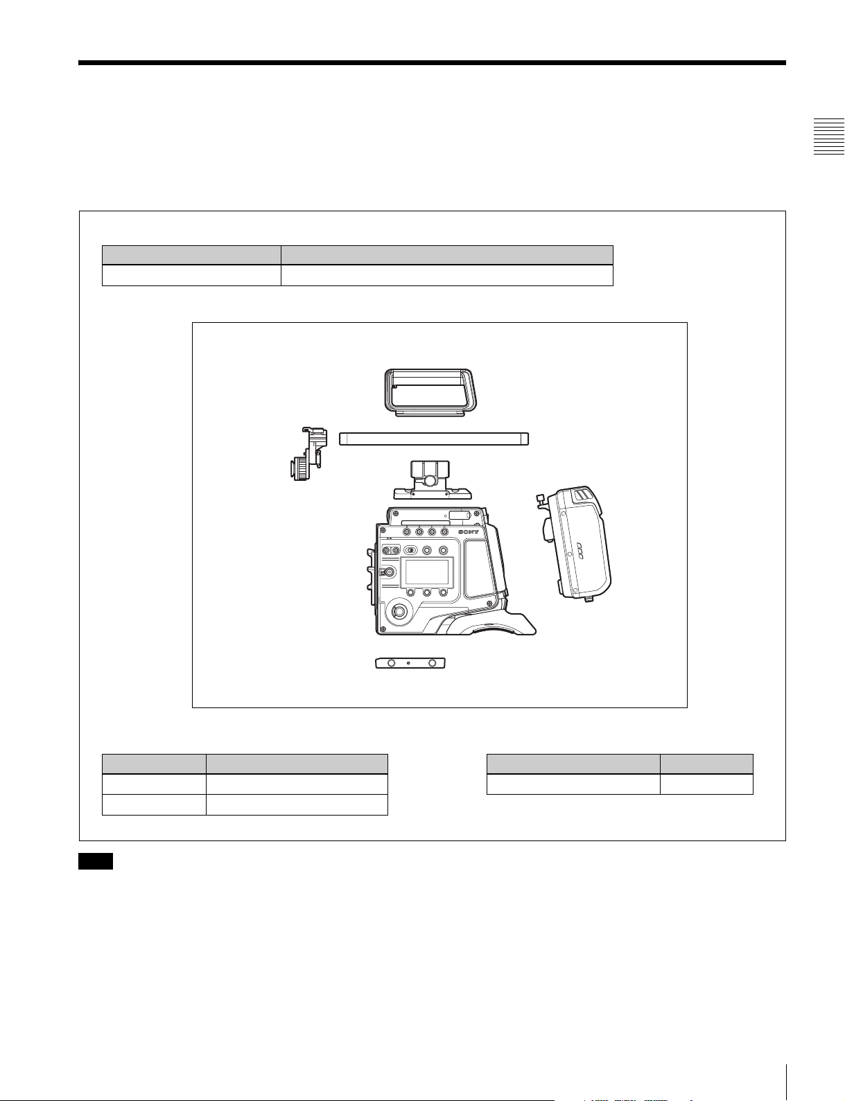
1-2 Example of System Configuration
The diagram below shows a system configuration example
to use of this camera.
This manual assumes the use of an optional Sony HD
Electronic Viewfinder.
Viewfinder
Product Model name
HD Electronic Viewfinder HDVF-C30WR, HDVF-C35W, HDVF-20A, HDVF-200
F65 Product Configuration
Center handle
Viewfinder mounting plate
For more information about the fittings, connections, or
use of additional equipment and accessories, see “Chapter
2 Installation and Preparations” (page 16) as well as the
operation manuals for the connected equipment.
Rod mounting plate
Chapter 1 Overview
19mm DIA carbon rod
Riser plate
Products for tripod mounting
Product Model name
Bridge Plate BP-5 (ARRIFLEX)
Shoulder Set S-1 (ARRIFLEX)
Note
If attaching and using products, such as a shoulder set,
from other manufacturers, check beforehand that the
product can be fitted correctly to the camera.
SR-R4
Video recorder
Product Model name
Portable Memory Recorder SR-R4
Example of System Configuration
9
Page 10
1-2-1 SR-R4 Docking System
An SR-R4 recorder can be docked on the rear of the camera head.
The SR-R4 power source is supplied via the camera’s DC IN connector.
Chapter 1 Overview
HDVF-C30WR
SR-R4
12 V DC power
Example of System Configuration
10
Page 11
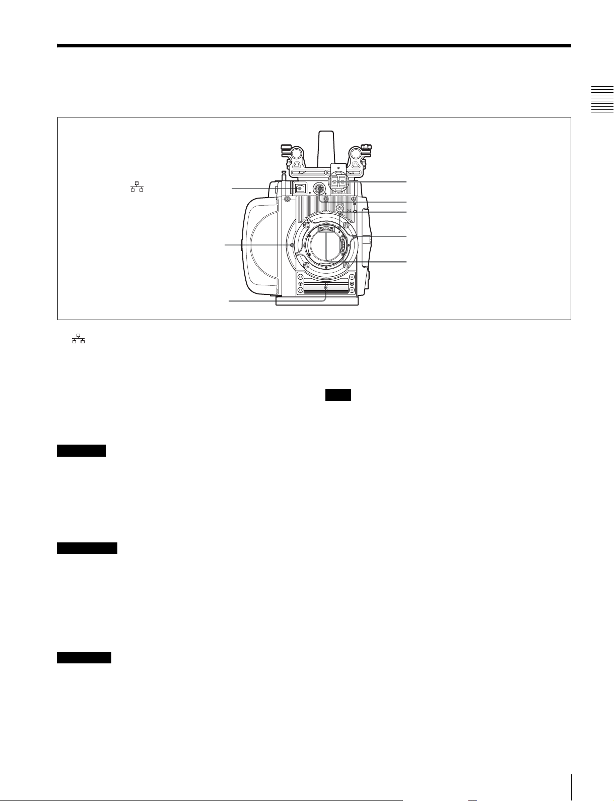
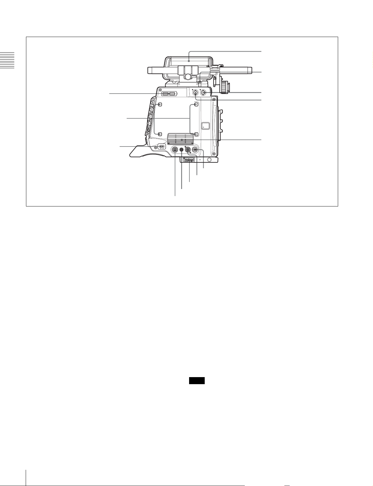
1-3 Locations and Functions of Parts
Front panel
a (Network) connector
Shutter emergency open
screw (page 49)
b Ventilation holes (intake)
a (Network) connector (RJ-45 type, 10BASE-T/
100BASE-TX)
Connects to a network cable when configuring the camera
from a web browser on a computer.
For a network cable connection, the IP address must be
configured in the Network menu in the VF menu.
For details, see “4-2-6 Network Menu” (page 42).
c Viewfinder shoe
d VF connector
Lens mount
e Lens fixing lever
f Hot shoe
Kabel, um Fehlfunktionen aufgrund von Störungen zu
vermeiden.
b Ventilation holes (intake)
Note
Make sure that a gap of about 8 mm (
11
/32 inch) is
maintained in front of the ventilation holes for cooling.
Chapter 1 Overview
CAUTION
• For safety, do not connect the connector for peripheral
device wiring that might have excessive voltage to this
port. Follow the instructions for this port.
• When you connect the network cable of the unit to
peripheral device, use a shielded-type cable to prevent
malfunction due to radiation noise.
ATTENTION
• Par mesure de sécurité, ne raccordez pas le connecteur
pour le câblage de périphériques pouvant avoir une
tension excessive à ce port. Suivez les instructions pour
ce port.
• Lors de la connexion du câble réseau de l’appareil au
périphérique, utilisez un câble blindé afin d’empêcher
tout dysfonctionnement dû au bruit de rayonnement.
VORSICHT
• Aus Sicherheitsgründen nicht mit einem
Peripheriegerät-Anschluss verbinden, der zu starke
Spannung für diese Buchse haben könnte. Folgen Sie
den Anweisungen für diese Buchse.
• Verwenden Sie beim Anschließen des Netzwerkkabels
des Geräts an ein Peripheriegerät ein abgeschirmtes
c Viewfinder shoe
Attach an optional viewfinder.
For details, see “2-3 Attaching a Viewfinder” (page 19).
d VF (viewfinder) connector (20-pin)
Connects to the cable supplied with a viewfinder
(optional).
e Lens fixing lever
When mounting a lens, turn the lever clockwise to secure
the lens. To remove the lens, turn the lever
counterclockwise.
If the lens fixing lever is difficult to operate due to the
shape of the lens or accessory being mounted, you can
remove the lever and attach it in a different orientation.
For details, see “2-2 Attaching a Lens” (page 17).
f Hot shoe
It is not used in this version.
Locations and Functions of Parts
11
Page 12
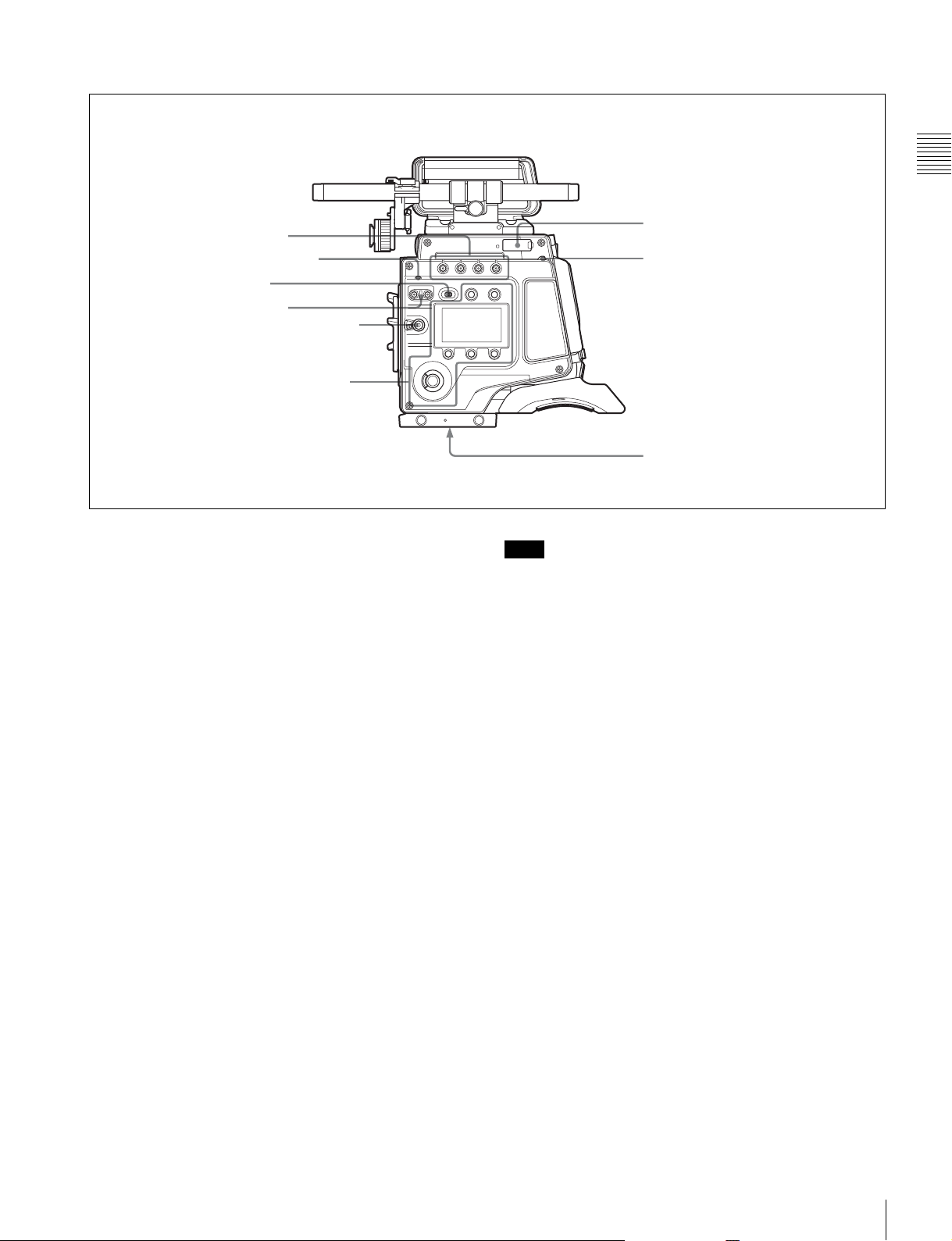
Left panel
i Handle
Chapter 1 Overview
a USB connectors
b Accessory receptacles
c CAM POWER switch
a USB connectors
USB 2.0 standard connector. Connect a CBK-WA01 Wi-Fi
Adapter (optional) to enable communication with wireless
LAN devices.
j Measure hook/
focus reference mark
k SDI OUT2 connector
l AUX
m Ventilation holes (exhaust)
h EXT. I/O connector
g LENS connector
f Wrench box
e DC OUT 24V 4A connector
d DC OUT 12V 4A connector
i Handle
The handle is attached to the top of the camera head at the
factory. It has two sizes of screw holes (
3
/8", 1/4") for
accessories on the upper side.
b Accessory receptacles
For mounting accessories using M3 screws. The depth of
the screws is 5 mm (
7
/32 inch).
c CAM POWER switch
Turns the camera power supply ON/OFF.
d DC OUT 12V 4A (12 V DC supply output)
connector
Supplies 12 V DC power source to accessories, when the
CAM POWER switch is in the ON position.
e DC OUT 24V 4A (24 V DC supply output)
connector
Supplies 24 V DC power source to accessories when there
is a 24 V DC supply connected to the DC IN connector and
the CAM POWER switch is in the ON position.
f Wrench box
Stores a 3 mm (
1
/8 inch) wrench for attaching/detaching
the handle.
g LENS connector (12-pin)
It is not used in this version.
h EXT. I/O (external control) connector (5-pin)
It is not used in this version.
j Measure hook/focus reference mark
Use as reference for focusing.
For actual measurement of the distance from a subject, you
can fix the end of a tape measure to the hook.
When shooting shallow depth-of-field images in high
resolution, it is recommended that you adjust the focus
using the camera or viewfinder magnification function.
k SDI OUT2 connector (BNC type)
Outputs the same signal as the SDI OUT1 connector on the
rear panel.
l AUX (display only)
This connector is for function expansion. It is not used in
this version.
m Ventilation holes (exhaust)
Note
Connectors and other parts positioned near the exhaust
vents may become hot.
Locations and Functions of Parts
12
Page 13
Right panel
Chapter 1 Overview
a ASSIGN buttons
b DIAGNOSIS indicator
c LOCK switch
d SHUTTER button
e REC button and LOCK switch
Display/menu operation block
a ASSIGN (assignable) buttons
You can assign various functions to these buttons, using
the subdisplay or the menu displayed in the viewfinder or
on a monitor.
ASSIGN button 1 is on the far left, and ASSIGN button 4
is on the far right.
For details, see “3-3-13 Assigning Functions to the
ASSIGN Buttons” (page 30).
b DIAGNOSIS indicator
Indicates the diagnostics status.
Lit green: Normal
Lit red: Error
Flashing red: Fatal error
If the red or flashing red indication continues, consult your
local Sony representative.
c LOCK switch
Locks operation of the side panel (excluding the REC and
PAGE buttons).
d SHUTTER button
On models with a mechanical rotary shutter (serial
numbers 10001 to 19999), the button switches between the
electronic shutter and the mechanical rotary shutter.
Press the “M.” button to switch to the mechanical rotary
shutter, or press the “E.” button to switch to the electronic
shutter. The button indicator for the selected shutter is lit.
The shutter indicator flashes when changing shutter.
f “Memory Stick”/
SD memory card section
g DOCK indicator
h Tripod receptacles (bottom)
Note
It takes about 20 to 40 seconds to change shutter.
e REC button and LOCK switch
The REC button starts/stops recording to the SR-R4
docked on the camera. The REC button indicator is lit
while recording. The indicator flashes as a warning if the
connected supply voltage drops.
When the LOCK switch is in the LOCK position, the REC
button cannot be operated.
The REC button cannot be operated during REC REVIEW,
PLAY, F.FWD, or REW mode on the SR-R4 to prevent
overwriting.
For details on warning indications, see “Warning/Error
Messages” (page 47).
f “Memory Stick”/SD memory card section
A slot to accommodate a “Memory Stick PRO Duo” is
provided behind the rubber cap. The access lamp turns red
when a “Memory Stick PRO Duo” is inserted into the slot,
and then turns off. It flashes red when reading to or writing
from the “Memory Stick PRO Duo.”
When the access lamp is flashing red, do not insert/remove
the “Memory Stick PRO Duo” or turn off the power.
g DOCK (docking) indicator
When an SR-R4 is docked, the light reception status of the
recorder connectors is displayed.
Green: Good
Ye l l ow : Caution level
Sensitivity has decreased, but signal can be transferred
Locations and Functions of Parts
13
Page 14
without error. Clean the recorder connector or replace
the connector optical module as soon as practicable.
Red: Light detection error
A light reception problem occurred, and signal cannot
be transferred correctly. Promptly clean the recorder
Chapter 1 Overview
connector or replace the connector optical module.
Off: No signal
For details about cleaning the connectors, see “Cleaning
the Recorder Connector” (page 50). For information
about replacing the optical module, consult your local
Sony representative.
h Tripod receptacles (bottom)
Mounting point for a tripod using
3
/8" tripod screws.
Display/menu operation block
Used to switch the monitor display between the subdisplay
and the viewfinder, and to operate the menus.
For details on menu operations, see “3-3-1 Basic
Operation of the Subdisplay” (page 24) and “3-4 VF Menu
Basic Operation” (page 32).
e PAGE button
Displays the next page when the subdisplay is in Settings
Change mode.
f BACK button
Cancels changes and returns to the previous screen when
the subdisplay is in Settings Change mode or when
displaying the menu in the viewfinder or on a monitor.
g MENU SEL (selection)/ENTER dial
Turn the dial to select items and press to enter when the
subdisplay is in Settings Change mode or when displaying
the menu in the viewfinder or on a monitor.
a VF DISPLAY button
b VF MENU button
c Subdisplay
d SETTING button
e PAGE button
f BACK button
g MENU SEL/ENTER dial
a VF DISPLAY (viewfinder display) button
Displays the status screen on the viewfinder and monitor.
For details about the information displayed, see “3-6
Viewing and Setting the Viewfinder Display” (page 34).
b VF MENU (viewfinder menu) button
Displays the menu screen on the viewfinder and monitor.
c Subdisplay
Displays the camera configuration settings. Press and hold
the SETTING button (1 second or longer) to enter Settings
Change mode.
d SETTING button
Press and hold for 1 second or longer to enter Settings
Change mode to change camera settings using the
subdisplay.
Locations and Functions of Parts
14
Page 15
Rear panel
a Recorder connector
Connects signal and power with the SR-R4 docked on the
camera.
Note
Attach the connector cap on the optical connector when
not connected to an SR-R4 to protect the connector.
b REC (record) indicator
The indicator is lit red while the recorder is recording.
You can slide the cover to hide the indicator.
a Recorder connector
Chapter 1 Overview
b REC indicator
c GENLOCK IN connector
d SHUTTER connector
e HD-Y OUT connector
f SDI OUT1 connector
g REMOTE connector
h DC IN indicator
i DC IN connector
j Cable clamp screw holes
i DC IN connector (LEMO 8-pin)
Connects to a power cable with the supplied power cable
connector.
For details, see “2-6 Preparing the Power Supply” (page
21).
j Cable clamp screw holes
Can be used to attach the supplied cable clamp.
There are also screw holes on the upper surface on the left
panel side.
c GENLOCK IN (external sync signal input)
connector (BNC type)
Used for input of an external gen-lock signal (HD 3-level
sync).
d SHUTTER (external shutter) connector
It is not used in this version.
e HD-Y OUT connector
Outputs the Y-signal for the HD analog component signal.
Used to synchronize external analog equipment.
f SDI OUT1 (SDI output 1) connector (BNC type)
Outputs an HD-SDI signal for connection to a monitor.
g REMOTE connector (8-pin)
It is not used in this version.
h DC IN (DC power input) indicator
A 10.5 V to 17 V indicator and 20 V to 30 V indicator are
provided. When the CAM POWER switch is turned ON,
the corresponding indicator lights up according to the
voltage of the power source.
Locations and Functions of Parts
15
Page 16
Installation and
Preparations
Chapter 2 Installation and Preparations
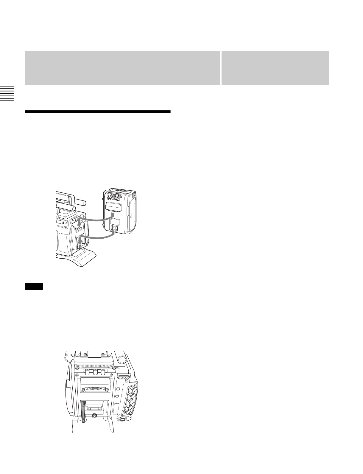
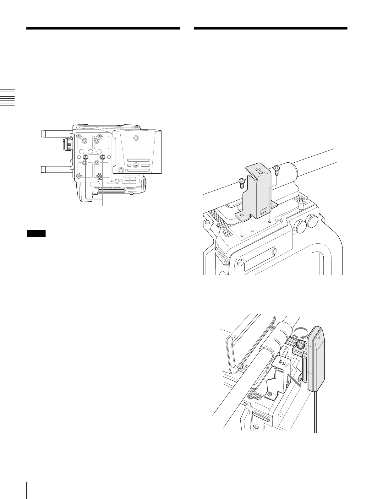
2-1 Mounting the SR-R4
The SR-R4 docks on the rear of the camera head.
For details about mounting the SR-R4, refer to the
Operation Manual of the SR-R4.
SR-R4
Chapter
• When mounting the SR-R4, fix the camera head on a
tripod in advance to keep the camera head stable.
For tripod mounting, see “2-4 Mounting the Camera on
a Tripod” (page 20).
• When the camera is used with the SR-R4 docked, make
sure that the camera is securely fixed and stable so that it
will not fall over.
2
Notes
• Always turn off the camera power supply when
mounting the SR-R4.
• The recorder connector for connecting the SR-R4 is an
optical connector. Attach the connector cap on the
optical connector when not connected to an SR-R4 to
protect the connector. After removing the cap, store it in
the position shown in the following figure for
safekeeping.
Mounting the SR-R4
16
Page 17
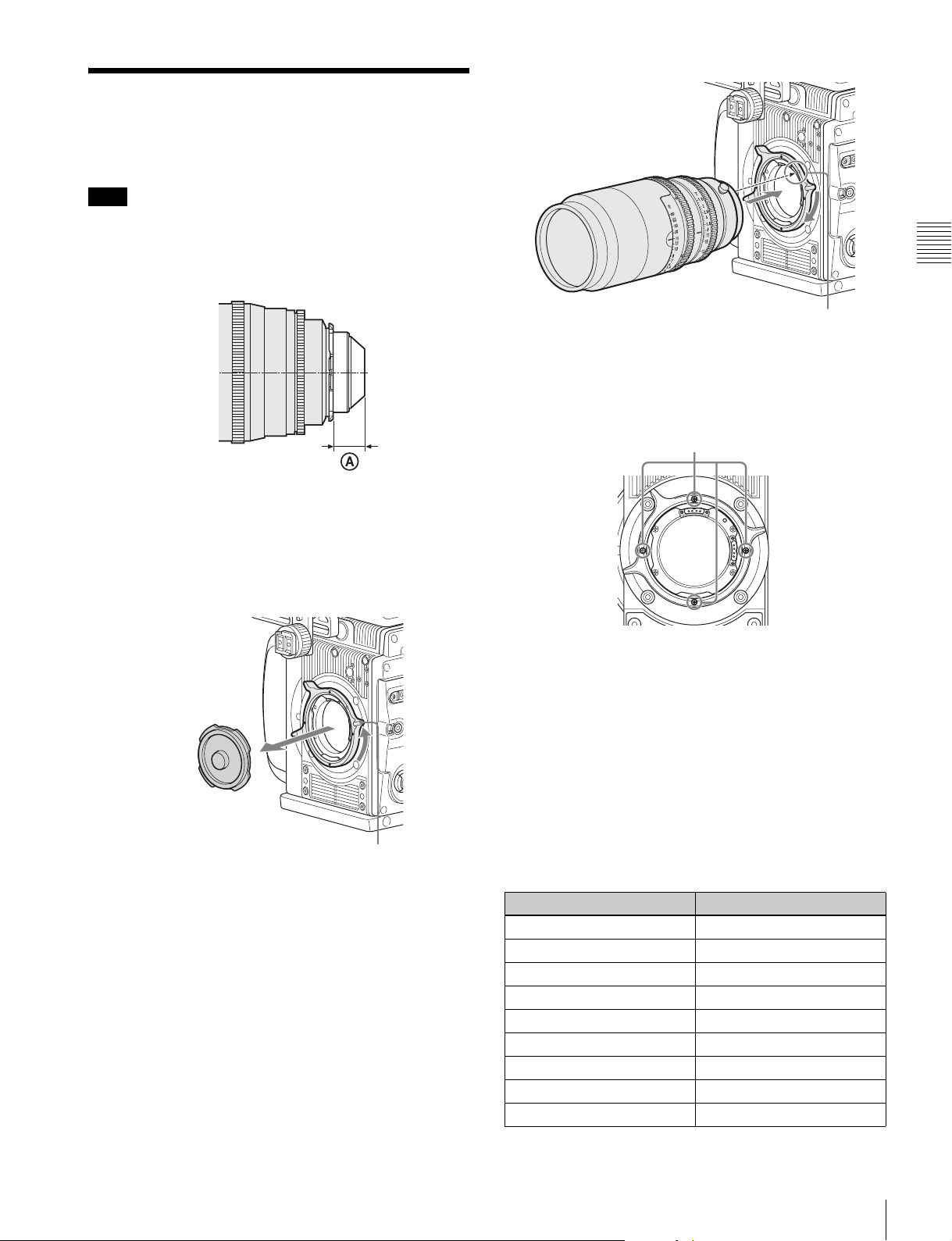
2-2 Attaching a Lens
Attach a lens that conforms to the PL lens mount.
Note
Always use a lens whose projection from the flange (A in
the figure) is less than 31.5 mm (1
that protrudes more than 31.5 mm (1
the internal filter.
For information on handling lenses, refer to the operation
manual for the lens.
1
/4 inch). Use of any lens
1
/4 inch) will damage
Chapter 2 Installation and Preparations
Lens alignment pin
Changing the position of the lens fixing lever
Remove the four screws from the face of the lens fixing
lever indicated in the figure. Change the position of the
fixing lever, reinsert the screws and securely tighten.
Remove screws
1
Rotate the lens fixing lever counterclockwise and
remove the lens mount cap from the lens mount.
Lens fixing lever
2
Align the lens’ alignment pin with the notch in the
upper part of the lens mount and insert the lens into the
mount.
3
While supporting the lens, rotate the lens fixing lever
clockwise to secure the lens.
Adjusting the flange focal length
The optical section uses materials not susceptible to
thermal expansion, so flange back adjustment is generally
not required. However, if you want to make an adjustment,
remove the lens mount and replace the shim with one of the
appropriate thickness. At shipment, a 0.06 mm
(0.0024 inch) shim is installed. The following replacement
shims are available.
For information about obtaining replaceable shims,
consult your local Sony representative.
Part number Thickness
4-260-711-02 0.02 mm (0.0008 inch)
4-260-711-12 0.03 mm (0.0012 inch)
4-260-711-22 0.04 mm (0.0016 inch)
4-260-711-32 0.05 mm (0.0020 inch)
4-260-711-42 (standard) 0.06 mm (0.0024 inch)
4-260-711-52 0.07 mm (0.0028 inch)
4-260-711-62 0.08 mm (0.0032 inch)
4-260-711-72 0.09 mm (0.0036 inch)
4-260-711-82 0.10 mm (0.0040 inch)
Attaching a Lens
17
Page 18
To change a shim
Note
Exercise care not to damage the internal wiring of the
camera when changing the shim. Modifying a shim,
scratching a surface, or introducing dust can change the
flange back distance and damage the camera such that it
cannot be restored to original condition, just as for a film
camera.
Chapter 2 Installation and Preparations
1
Remove the lens mount screws (6).
Lens mount screws
2
Pull the lens mount out by about 10 mm (13/32 inch)
and remove the shim carefully.
Pass the shim slit over the wiring, taking care not to
pull the wiring, when removing the shim.
Shim alignment pins
4
Reattach the lens mount in its original position, and
fasten the screws.
18
Note
Pulling the lens mount out by more than 20 mm
3
(
/4 inch) risks damage to the internal wiring.
3
Insert the replacement shim using the shim slit to clear
the wiring, and align the camera screw holes and shim
alignment pins.
Attaching a Lens
Page 19
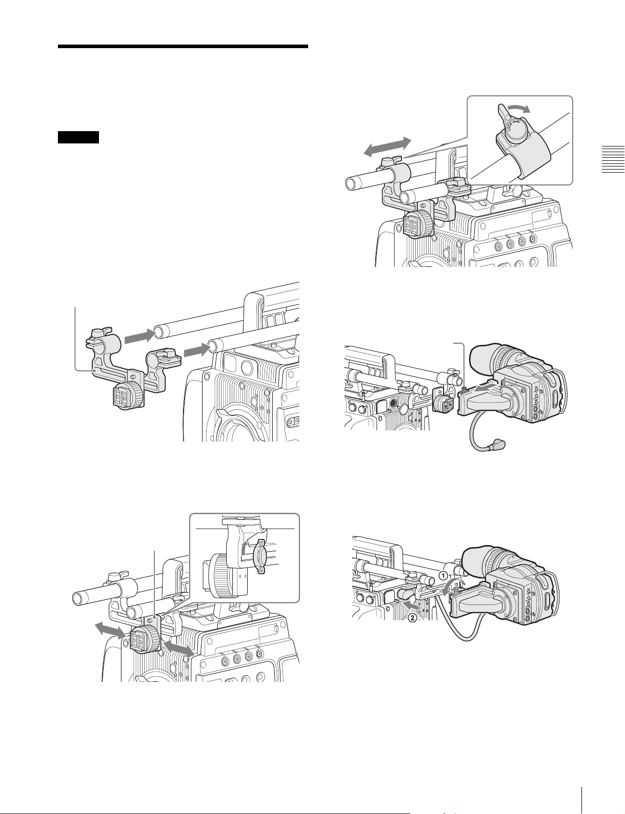
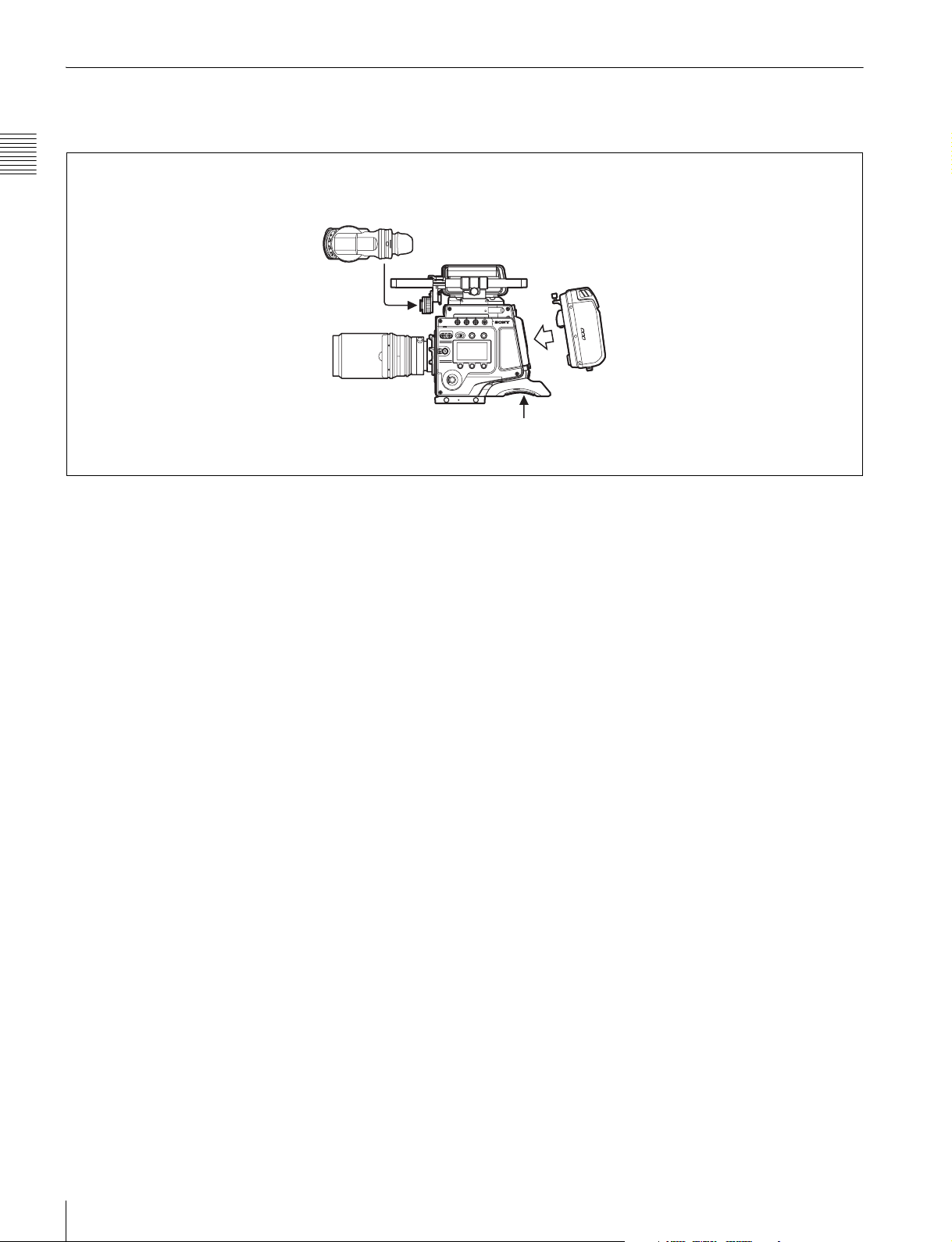
2-3 Attaching a Viewfinder
Caution
When the viewfinder is attached, do not leave the camera
with the eyepiece facing the sun. Direct sunlight can enter
through the eyepiece, be focused in the viewfinder and
cause fire.
For details on the viewfinder, refer to the instruction
manual of the viewfinder.
1
Pass the viewfinder mounting plate over the two rods.
Viewfinder mounting plate
3
Slide the viewfinder mounting plate forward/backward
into position, and then turn the lever to lock it into
position.
4
Fit the viewfinder to the viewfinder shoe and slide the
viewfinder horizontally.
The viewfinder stopper automatically pops down.
Stopper
Chapter 2 Installation and Preparations
2
Slide the slide panel left/right into position, and then
turn the lever on the rear of the slide panel to lock it
into position.
Slide panel
5
Set the viewfinder to the most convenient position,
tighten the viewfinder positioning ring (1 in the
figure below), and connect the viewfinder cable to the
VF connector of the camera (2 in the figure below).
To detach the viewfinder
Loosen the viewfinder positioning ring, pull up the
viewfinder stopper, then pull out the viewfinder by sliding
it in the direction opposite than when attaching.
Attaching a Viewfinder
19
Page 20
2-4 Mounting the Camera
2-5 Mounting the
on a Tripod
The camera mounts on a tripod using two 3/8" tripod
receptacles that fit into the base of the camera head.
For details about mounting on a tripod, refer to the
Chapter 2 Installation and Preparations
operation manual of the tripod.
Tripod receptacles
Notes
• Select an appropriate hole, considering the balance of the
weight of the camera. If an inappropriate hole is selected,
the camera may fall over.
• Check that the size of the selected hole matches that of
the screw of the tripod. If they do not match, the camera
cannot be attached to the tripod securely.
CBK-WA01
A CBK-WA01 Wi-Fi Adapter can be mounted on the
camera using an optional Wi-Fi mounting bracket (part
number: 4-418-596-01) for connecting Wi-Fi capable
devices to the camera.
For information about obtaining the Wi-Fi mounting
bracket, consult your local Sony representative.
1
Attach the Wi-Fi mounting bracket onto the camera.
2
Place the protrusions on the rear of the CBK-WA01
into the holes in the mounting bracket, and fasten the
screw to secure the CBK-WA01 to the bracket.
Mounting the Camera on a Tripod / Mounting the CBK-WA01
20
Page 21
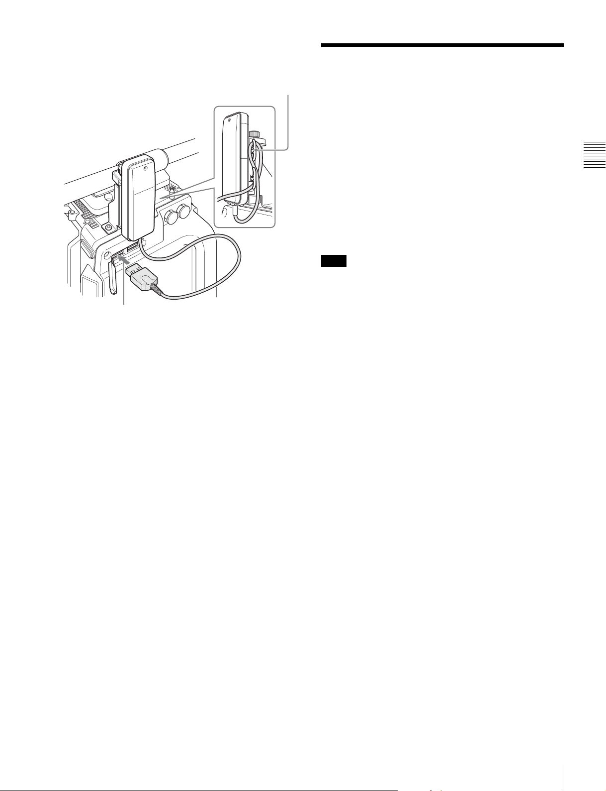
3
Connect the CBK-WA01 cable to a USB connector on
the camera. Wrap excess cable length around the cable
holder.
Cable holder
2-6 Preparing the Power Supply
This camera operates on DC 12 V (10.5 V to 17 V).
To supply power to the camera, attach the supplied 8-pin
power cable connector to a commercially available
shielded cable, and then connect the cable to the DC IN
connector (LEMO 8-pin) on the camera.
For details on connector pin assignments, see “Connector
Pin Assignments” (page 55) in the Appendix. For details
on the pin connections, consult your local Sony
representative.
Note
When using the SR-R4 docked on the camera, supply
DC 11 V to 17 V power source.
To turn on the camera
Set the CAM POWER switch to the ON position, and the
camera is turned on.
Power is also supplied to viewfinder connected to the VF
connector.
12 V or 24 V power can be fed to accessories via the DC
OUT connectors. To supply 24 V power to accessories, a
24 V DC input power supply must be connected to the DC
IN connector of the camera.
Chapter 2 Installation and Preparations
For the pin assignment for the 24 V power supply DC IN
connector, see “Connector Pin Assignments” (page 55) in
the Appendix.
Preparing the Power Supply
21
Page 22
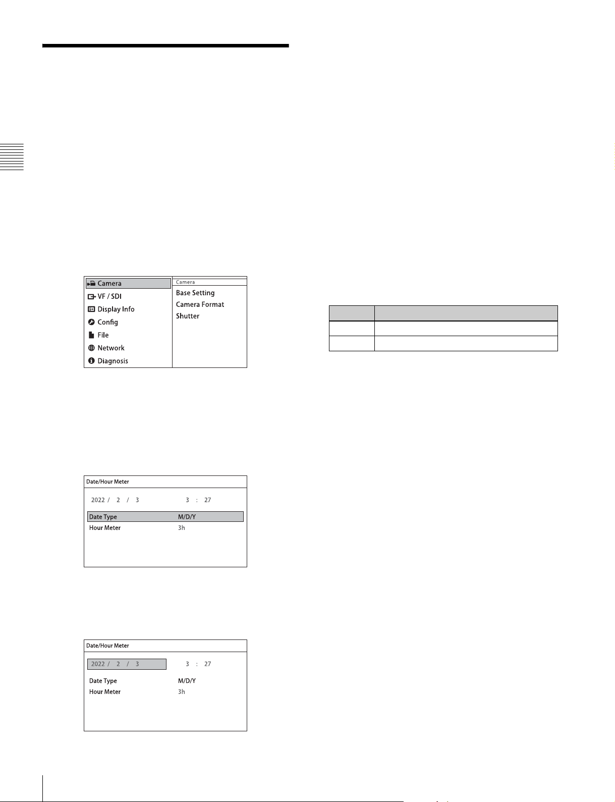
2-7 Setting the Date and Time
When the camera is used for the first time, the menu for
setting the date and time is displayed in the viewfinder. Set
the current date and time on the <Date/Hour Meter> page
in the Config menu.
Chapter 2 Installation and Preparations
To set the menu using a monitor screen, connect a monitor
to an SDI OUT connector.
1
Turn on the camera power supply.
2
Press the VF MENU button.
The menu appears in the viewfinder.
6
Turn the MENU SEL/ENTER dial to set the date (year,
month, day).
Turning the MENU SEL/ENTER dial moves to the
next digit. Select the day, then press the MENU SEL/
ENTER dial to confirm the setting.
7
Turn the MENU SEL/ENTER dial to select Time, then
press the MENU SEL/ENTER dial.
The time becomes editable.
8
Turn the MENU SEL/ENTER dial to set the time, then
press the MENU SEL/ENTER dial.
9
Turn the MENU SEL/ENTER dial to select Date Type,
then press the MENU SEL/ENTER dial.
10
Turn the MENU SEL/ENTER dial to select the date
format, then press the MENU SEL/ENTER dial.
You can select one of the following display formats.
Setting Example display (18th December, 2011)
Y/Mn/D 2011/12/18
Mn/D 12/18
3
Turn the MENU SEL/ENTER dial to select Config,
then press the MENU SEL/ENTER dial.
4
Turn the MENU SEL/ENTER dial to select Date/Hour
Meter, then press the MENU SEL/ENTER dial.
The <Date/Hour Meter> page appears.
5
Turn the MENU SEL/ENTER dial to select Date, then
press the MENU SEL/ENTER dial.
The date becomes editable.
11
When finished, press the VF MENU button to exit
menu operation.
Setting the Date and Time
22
Page 23

Basic Adjustments and
Settings
3-1 Basic Operation of the Camera
The F65 does not perform processing of images on-site,
instead you shoot in a mode that presumes images will be
processed in post-production, in much the same way you
would operate a film camera.
When shooting, the camera gain is fixed and the sensitivity
is set using a light meter. The base sensitivity is EI 800, and
can be adjusted over a range of ± 2 stops in 1/3 stop
increments. When the sensitivity is set to a value higher
than the base EI 800, the main camera output signal
becomes darker. However, the gain of the images in the
viewfinder and on the monitor connected to the SDI OUT
connector are automatically adjusted in response to the
sensitivity setting to provide appropriate monitoring
capability while shooting.
The full latitude does not change when the sensitivity
setting is changed, but the dynamic range and noise floor
changes in post-production with suitable processing.
When the sensitivity is set high, the dynamic range
increases on one hand, while the noise in dark areas also
increases. Conversely, when the sensitivity is set low, the
dynamic range decreases but the noise in the dark areas
also decreases.
Chapter
3
3-2 Camera Settings
The camera can be configured from the following devices.
Subdisplay
You perform the basic setup configuration using the
subdisplay on the side of the camera head.
The basic settings (settings page) is displayed on the
subdisplay when power is applied to the camera. Press and
hold the SETTING button for 1 second or longer to switch
to Settings Change mode. The MENU SEL/ENTER dial,
SETTING button and BACK button are used for Settings
Change mode operation.
For details about settings on the subdisplay, see “3-3 Basic
Settings using the Subdisplay” (page 24). For details about
the subdisplay menu list, see “4-1 Subdisplay Menu List”
(page 37).
Viewfinder or monitor
Detailed settings can be performed by displaying the menu
(VF menu) in the viewfinder or on a monitor connected to
an SDI OUT connector.
Press the VF MENU button on the side of the camera to
display the VF menu in the viewfinder or on a monitor. The
VF MENU button, MENU SEL/ENTER dial, and BACK
button are used for VF menu operation.
Chapter 3 Basic Adjustments and Settings
The white balance can be set to 3200K (tungsten), 4300K
(tungsten), or 5500K (daylight).
For details about VF menu operations, see “3-4 VF Menu
Basic Operation” (page 32). For details about the VF
menu list, see “4-2 VF Menu List” (page 38).
Web browser
If the camera is connected to a network, the menus can be
displayed in a web browser on a computer. The settings
displayed are almost identical to the display in the
viewfinder or on a monitor.
For details about web browser operations, see “Menu
Operation using a Web Browser” (page 57).
Basic Operation of the Camera / Camera Settings
23
Page 24
Tablet device
1
If the camera is used with the optional Wi-Fi adapter
(CBK-WA01), the menus can be displayed on a tablet
device, such as an iPad, via a wireless LAN. The settings
displayed are almost identical to the display in the
viewfinder or on a monitor.
3-3 Basic Settings using the Subdisplay
For details about tablet device operations, see “Menu
Operation using an iPad” (page 58).
Chapter 3 Basic Adjustments and Settings
Basic settings of the camera can be easily performed using
the subdisplay. The items set on the subdisplay can also be
set using the VF menu.
3-3-1 Basic Operation of the Subdisplay
The buttons and dial shown below are used for operation of
the subdisplay.
Side panel of the camera head
Subdisplay
SETTING button
PAGE button
BACK button
MENU SEL/ENTER dial
To display the settings pages
After the camera is turned on, the startup screen is
displayed on the subdisplay for several seconds, after
which the settings page is displayed.
Pressing the PAGE button advances to the next page.
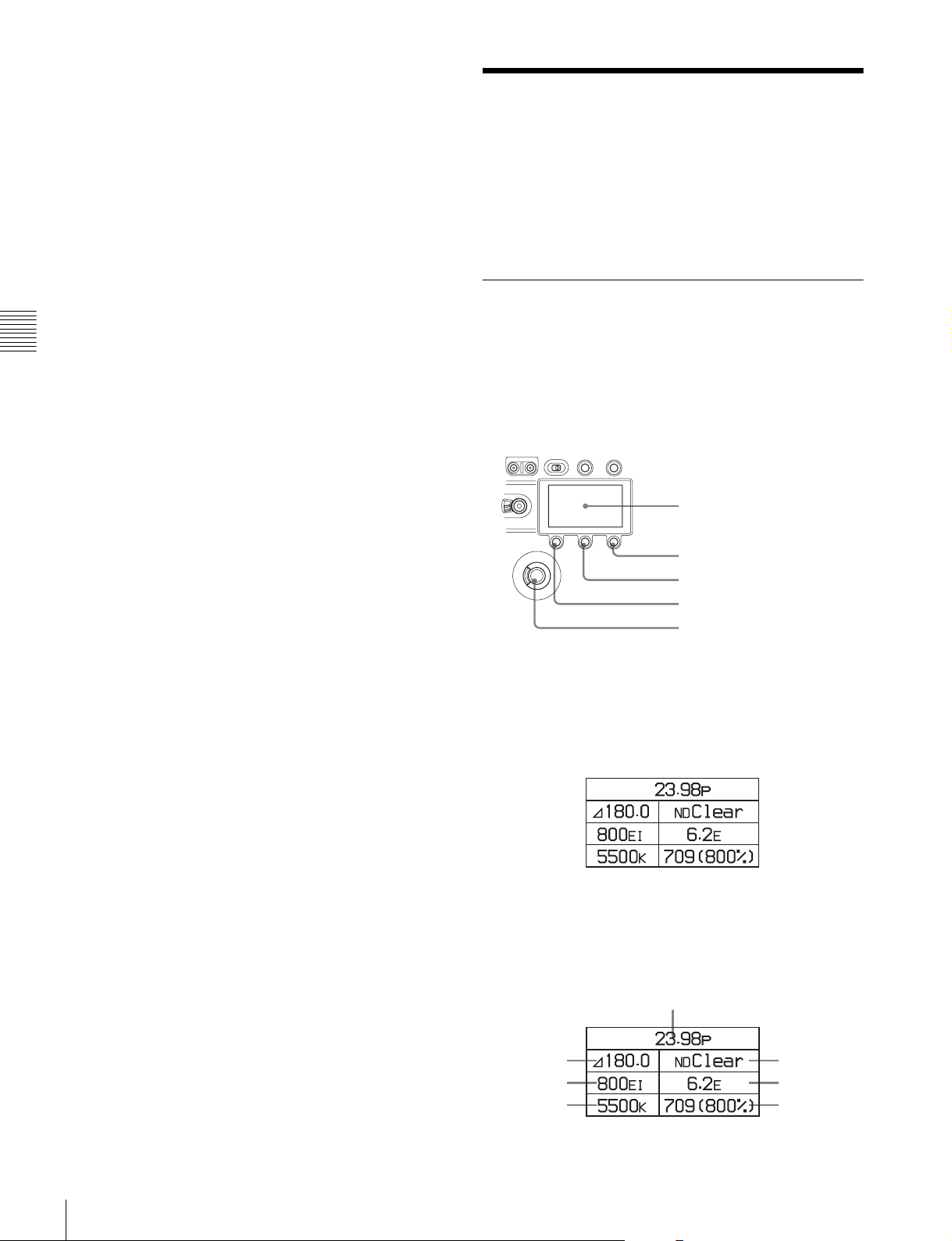
The following items can be set or checked on each settings
page.
Settings page 1
23
4
6
5
7
Basic Settings using the Subdisplay
24
Page 25
1 Video format
2 Shutter value
3 ND filter
4 Sensitivity (EI value)
5 Highlight latitude
6 Color temperature
7 Look-up table (LUT)
Select screen (e.g. shutter value)
Settings page 2
23
1 Fan operating mode
2 Vo l t a g e s
3 Media remaining
4 Timecode
Settings page 3
12
34
56
1 ASSIGN button 1
2 ASSIGN button 2
3 ASSIGN button 3
4 ASSIGN button 4
5 Subdisplay brightness
6 Self diagnostics
4
1
On this screen, turn the MENU SEL/ENTER dial to select
an item. Press the MENU SEL/ENTER dial to display the
change screen for the item.
Change screen (e.g. shutter value)
Chapter 3 Basic Adjustments and Settings
The current value of the setting is displayed at the top right
of the screen. Turn the MENU SEL/ENTER dial to select
the value, then press the MENU SEL/ENTER dial.
The value for the selected item is entered, and the display
returns to the previous page.
To cancel a changed setting
Press the BACK button before confirming the changed
setting.
The setting is restored to the original value, and the display
returns to the previous page.
Note
Pressing the VF MENU button enables menu operation in
the viewfinder or on a monitor, and disables operation
using the subdisplay.
To change a setting
Press and hold the SETTING button for 1 second or longer.
The screen changes to Settings Change mode, and the
selected item is displayed in inverse text.
In this mode, the item you want to set is selected by turning
the MENU SEL/ENTER dial. When the item you want to
set is shown in inverse text, press the MENU SEL/ENTER
dial.
Where there are multiple configuration items, the select
screen is displayed.
Subdisplay when VF MENU button is pressed
3-3-2 Setting the Video Format
The camera supports the following video format settings.
Setting Frame rate (fps) Scan mode
23.98p 23.98 Progressive
29.97p 29.97 Progressive
59.94p 59.94 Progressive
24p 24 Progressive
25p 25 Progressive
Basic Settings using the Subdisplay
25
Page 26
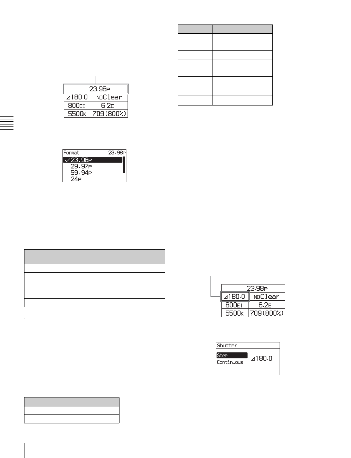
Changing the video format
1
Select the video format on settings page 1, then press
the MENU SEL/ENTER dial.
Settings page 1
Video format
Step No. Shutter angle
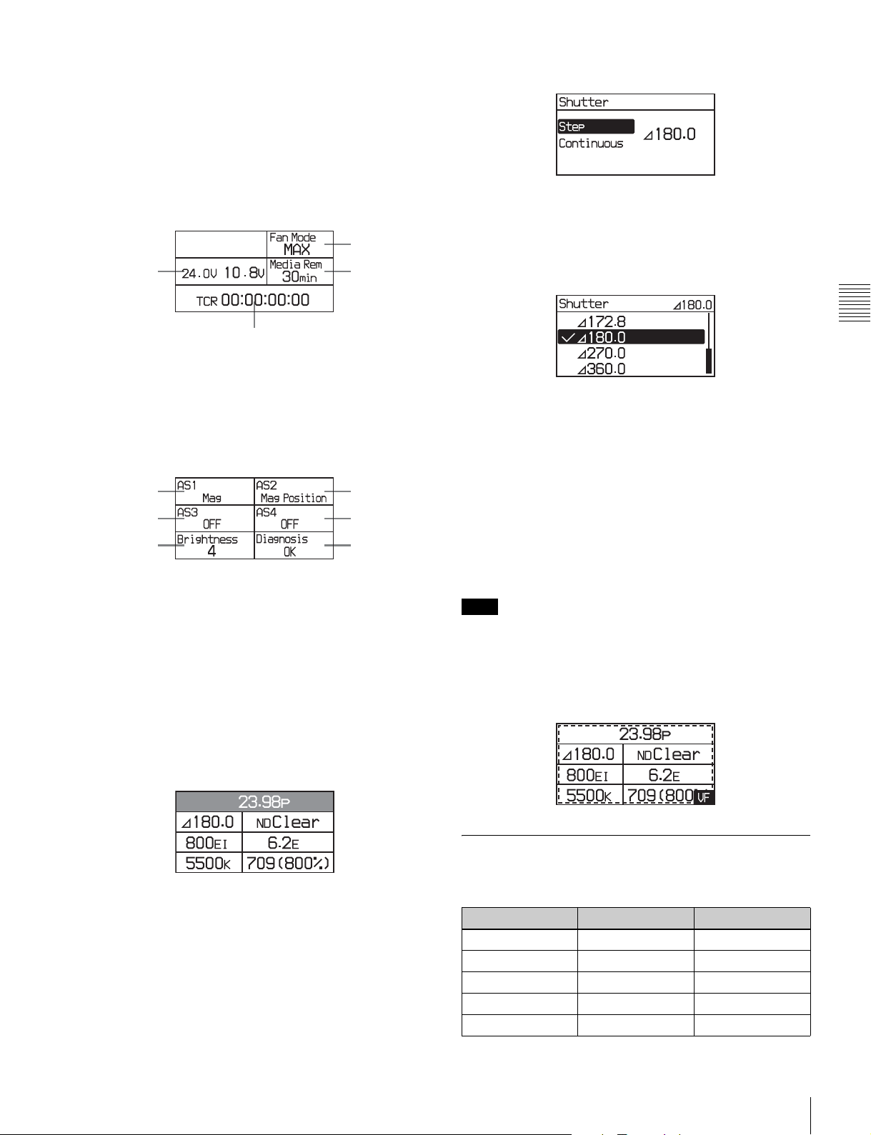
345.0
490.0
5 144.0
6 150.0
7 172.8
8 180.0
9
10
a) Selectable for the electronic shutter only.
270.0
360.0
a)
a)
2
Chapter 3 Basic Adjustments and Settings
Turn the MENU SEL/ENTER dial to select the video
format, and press the MENU SEL/ENTER dial.
To set using the VF menu
Set on the <Format> page in the Camera menu (page 39).
VF and SDI OUT connectors output format
Setting the camera main video format automatically
determines the signal format that is output on the VF and
SDI OUT connectors.
Camera image VF connector
output
23.98p 23.98PsF 23.98PsF
29.97p 29.97PsF 29.97PsF
59.94p 59.94i 59.94i
24p 24PsF 24PsF
25p 25PsF 25PsF
SDI OUT connector
output
The corresponding shutter speeds vary according to the
frame frequency and frame rate of the selected video
format.
Continuous mode (ECS)
The shutter value can be changed smoothly in continuous
mode in the range 4.2° to 360.0° (electronic shutter) or
11.2° to 180.0° (mechanical rotary shutter).
To obtain your desired shutter value quickly, select a value
nearest your desired one in Step mode, then switch to
Continuous mode and adjust the shutter value.
Changing the shutter value in Step mode
In Step mode, one of the registered shutter values can be
selected.
1
Select the shutter value on settings page 1, then press
the MENU SEL/ENTER dial.
Settings page 1
Shutter value
3-3-3 Setting the Shutter Value
The shutter of the camera can be viewed and adjusted, with
settings displayed as shutter angles, just as for a film
camera. Two operation methods are available for the
adjustment: stepwise and continuous.
Step mode
Frequently-used shutter angle values can be selected,
enabling step selection of the shutter values.
Step No. Shutter angle
111.2
222.5
Basic Settings using the Subdisplay
26
2
Select [Step], then press the MENU SEL/ENTER dial.
Page 27
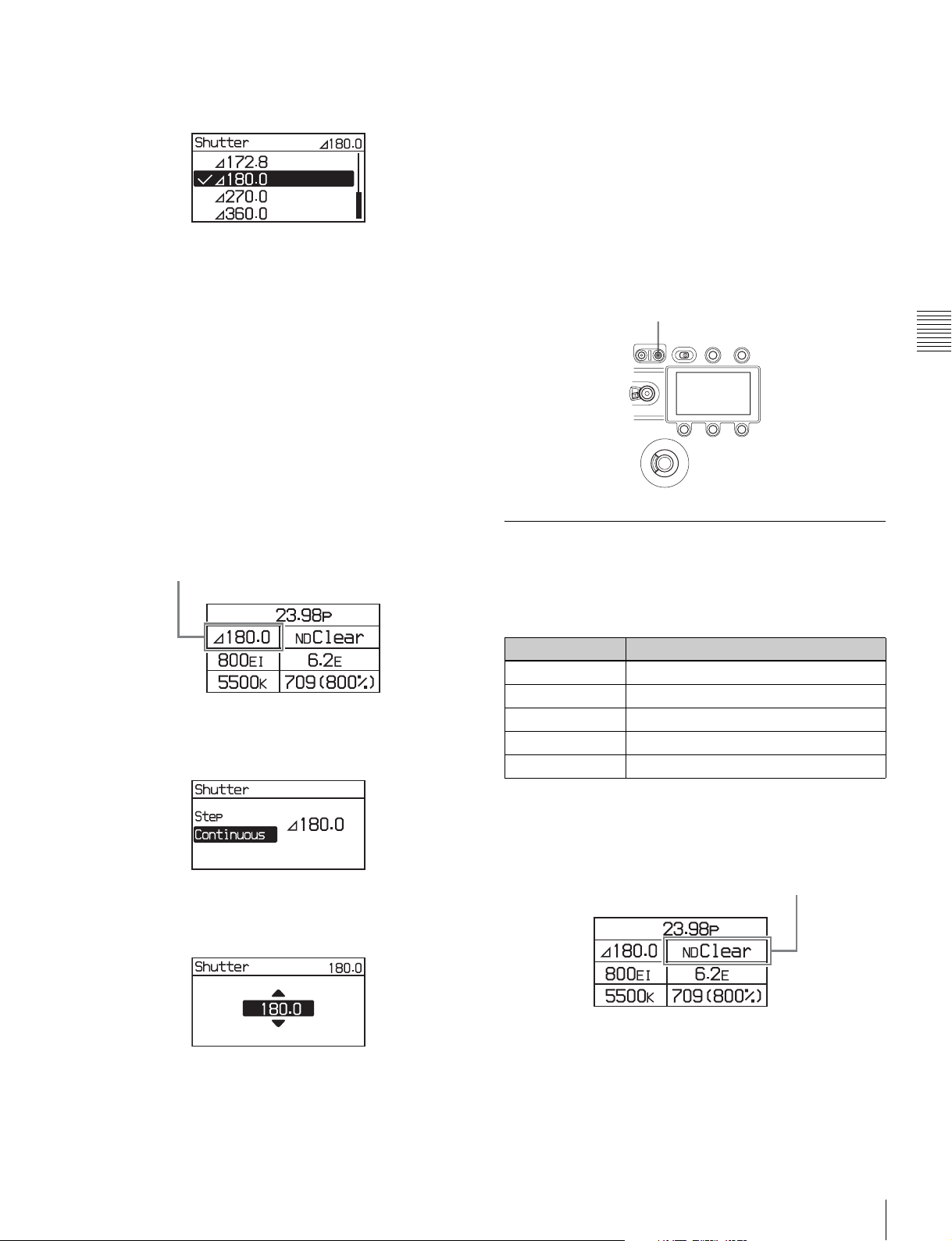
3
Turn the MENU SEL/ENTER dial to select the shutter
value.
You do not need to press the MENU SEL/ENTER dial to
set a value. The shutter value changes are reflected on the
camera as the MENU SEL/ENTER dial is turned. Pressing
the BACK button cancels the shutter setting, and restores
the previous value.
To set using the VF menu
Set on the <Shutter> page in the Camera menu (page 39).
Selecting an arbitrary shutter value
In Continuous mode, an arbitrary shutter value can be set.
1
Select the shutter value on settings page 1, then press
the MENU SEL/ENTER dial.
the BACK button cancels the shutter setting, and restores
the previous value.
To set using the VF menu
Set on the <Shutter> page in the Camera menu (page 39).
When not using the shutter
Press the “E.” button if the E. button indicator on the
SHUTTER button is on.
The shutter is switched off, and the E. button indicator
turns off.
E. button
Chapter 3 Basic Adjustments and Settings
Settings page 1
Shutter value
2
Select [Continuous], then press the MENU SEL/
ENTER dial.
3
Turn the MENU SEL/ENTER dial to select the shutter
value.
3-3-4 Selecting an ND Filter
The camera has built-in optical ND filters that can be used
to match the illumination and natural lighting conditions.
The following filters can be selected.
Filter density Description
Clear No filter is used.
0.9 1/8 optical transmittance
1.2 1/16 optical transmittance
1.5 1/32 optical transmittance
1.8 1/64 optical transmittance
1
Select the ND filter on settings page 1, and press the
MENU SEL/ENTER dial.
Settings page 1
ND filter
23.98p
180.0 Clear
800EI
5500K
ND
6.2 E
709(800%)
You do not need to press the MENU SEL/ENTER dial to
set a value. The shutter value changes are reflected on the
camera as the MENU SEL/ENTER dial is turned. Pressing
2
Turn the MENU SEL/ENTER dial to select the ND
filter, then press the MENU SEL/ENTER dial.
Basic Settings using the Subdisplay
27
Page 28

To set using the VF menu
Set the ND Filter on the <Base Setting> page in the
Camera menu (page 39).
3-3-5 Setting the Sensitivity (EI Value)
Chapter 3 Basic Adjustments and Settings
The sensitivity is determined by the EI value (Exposure
Index). The viewfinder and monitor image brightness
changes to match the EI value. But it has no affect on the
recorded image.
The camera supports the following sensitivity settings:
200EI, 250EI, 320EI, 400EI, 500EI, 640EI, 800EI,
1000EI, 1250EI, 1600EI, 2000EI, 2500EI, and 3200EI.
1
Select the sensitivity on settings page 1, then press the
MENU SEL/ENTER dial.
Settings page 1
The latitude is automatically assigned one of the following
values, depending on the sensitivity (EI value) setting.
Sensitivity (EI value) Latitude
200EI 4.2E
250EI 4.5E
320EI 4.9E
400EI 5.2E
500EI 5.5E
640EI 5.9E
800EI 6.2E
1000EI 6.5E
1250EI 6.9E
1600EI 7.2E
2000EI 7.5E
2500EI 7.9E
3200EI 8.2E
The value is displayed in “xx E” format and represents the
highlight latitude displayed as a lens aperture value (fstop) for key light from a gray chart with 18% reflectivity.
Settings page 1
Sensitivity
2
Turn the MENU SEL/ENTER dial to select the EI
value, then press the MENU SEL/ENTER dial.
To set using the VF menu
Set the Exposure Index on the <Base Setting> page in the
Camera menu (page 39).
3-3-6 Checking the Highlight Latitude
The highlight latitude can be checked on settings page 1 on
the subdisplay.
Highlight latitude
3-3-7 Setting the Color Temperature
The color temperature can be set to 3200K (tungsten),
4300K (tungsten), or 5500K (daylight) to match the
shooting environment.
1
Select the color temperature on settings page 1, then
press the MENU SEL/ENTER dial.
Settings page 1
23.98p
180.0 Clear
800EI
5500K
Color temperature
2
Turn the MENU SEL/ENTER dial to select the color
temperature, then press the MENU SEL/ENTER dial.
ND
6.2 E
709(800%)
Basic Settings using the Subdisplay
28
Page 29

To set using the VF menu
Set the Color Temperature on the <Base Setting> page in
the Camera menu (page 39).
3-3-8 Setting the SDI OUT Output
To set using the VF menu
Set on the <LUT> page in the VF/SDI menu (page 40).
3-3-9 Selecting the Fan Operating Mode
You can set the operating mode of the camera’s built-in
fans. The mode can be set to silence the fan speed noise or
to provided maximum cooling to suit the shooting
environment. You can select one of the following operating
modes.
LUT
The image output from the SDI OUT connectors is
configured using a Look-up table (LUT). The images shot
with the camera are intended for processing in postproduction, and are not suitable for checking the results of
shooting as-is on the scene. Setting a LUT changes the
tone of the image displayed on a monitor connected to an
SDI OUT connector, without affecting the main RAW
image output, for ease of monitoring. The following LUTs
can be configured.
Setting Description
709(800%) (default) Outputs a signal that extends the
S-Log Outputs a non-adjustable signal that
1
Select the monitor look-up table on settings page 1,
then press the MENU SEL/ENTER dial.
Settings page 1
dynamic range by up to 800% in
video terms based on ITU-R709 with
conventional monitor gamma.
uses S-Log gamma.
Setting Fan operation
Auto1 The fans are automatically controlled
Auto2 The fans are automatically controlled
Min In this mode, quiet fan operation is
Max (default) Fan rotation set at the maximum speed
a) The coupling of the fan control with recording is available only when an
SR-R4 is docked on the camera.
Note
according to the internal temperature,
regardless of whether recording or not.
according to the internal temperature.
When recording, the fans are controlled
to maintain quiet operation.
maintained regardless of whether
recording or not. This is the best mode if
recording for more than 30 minutes in a
quiet environment, such as a concert
hall. Use this mode in environments with
ambient temperature of less than 30°C
(86°F).
to lower the internal temperature.
a)
Even when Min mode is selected, the speed of the fans
automatically increases if the internal temperature rises.
Chapter 3 Basic Adjustments and Settings
LUT
2
Turn the MENU SEL/ENTER dial to select the lookup table to apply, then press the MENU SEL/ENTER
dial.
1
Select the fan operating mode on settings page 2, then
press the MENU SEL/ENTER dial.
Settings page 2
Fan operating mode
Fan Mode
MAX
24.
OV
10.8
Media Rem
V
30min
0 0:0 0:0 0:0 0TCR
Basic Settings using the Subdisplay
29
Page 30

2
Turn the MENU SEL/ENTER dial to select the
operating mode, then press the MENU SEL/ENTER
dial.
Settings page 2
Media remaining
To set using the VF menu
Set on the <Fan Mode> page in the Config menu (page 41).
Chapter 3 Basic Adjustments and Settings
3-3-10 Checking the Voltage
The voltage of the power supplies connected to the camera
can be checked on settings page 2 on the subdisplay.
Settings page 2
Voltages
Fan Mode
MAX
24.
OV
10.8
Media Rem
V
30min
0 0:0 0:0 0:0 0TCR
The voltage of the 24 V supply is displayed on the left, and
the voltage of the 12 V supply on the right. If power is not
supplied, “- -” is displayed.
If the voltage falls to the Near End level, the voltage
indicator starts flashing. If the voltage falls to the End
level, the indicator starts flashing rapidly.
Fan Mode
MAX
24.
OV
10.8
Media Rem
V
30min
0 0:0 0:0 0:0 0TCR
3-3-12 Checking the Timecode
When the SR-R4 recorder is docked with the camera, the
SR-R4 timecode can be checked on settings page 2 on the
subdisplay.
Settings page 2
Timecode
3-3-13 Assigning Functions to the ASSIGN Buttons
Separate functions can be assigned to each of the ASSIGN
buttons 1 to 4 on the side of the camera body.
The following functions are assigned to the buttons by
factory default.
The voltage Near End and End levels can be set on the
<Battery Alarm> page in the Config menu (page 41).
For details, see “3-6-3 Setting the Voltage Warning
Values” (page 35).
3-3-11 Checking the Remaining Media
When the SR-R4 recorder is docked with the camera, an
estimate of the remaining recording time (in minutes) on
the memory card can be checked on settings page 2 on the
subdisplay.
Basic Settings using the Subdisplay
30
Button Function
ASSIGN 1 Mag
ASSIGN 2 Mag Position
ASSIGN 3 Hi/Lo Key
ASSIGN 4 Off
Page 31

Functions that can be allocated to the ASSIGN
buttons
Menu indication Function
OFF No function is allocated.
Mag Displays a magnified image in the
viewfinder and on the SDI OUT
connectors.
Each time the button is pressed, the
magnification changes between 2times, 4-times, and Off. When the
magnification is 2-times or 4-times, the
ASSIGN button allocated with the Mag
function is lit.
The display returns to normal after
about 30 seconds.
Mag Position Selects the position of the image that
is magnified by the Mag function.
There are nine points on the screen
that can act as the center point of the
magnified image. This function sets
the position of the magnified image as
an area centered on one of these
points. Each time the button is
pressed, the area moves one position
from top left to bottom right. When the
display is magnified, the ASSIGN
button allocated with the Mag Position
function is lit.
Hi/Lo Key Temporarily changes LUT for checking
the high-luminance brightness and
low-luminance darkness of the image
in the viewfinder and from the SDI
OUT connectors. The button toggles
between high-luminance check (gain
reduction), low-luminance check (gain
amplification), and normal.
The display returns to normal after
about 30 seconds.
Fan Mode Switches the fan operating mode.
For details on the fan operating mode,
see “3-3-9 Selecting the Fan
Operating Mode” (page 29).
2
Turn the MENU SEL/ENTER dial to select the
function to assign, then press the MENU SEL/ENTER
dial.
To set using the VF menu
Set on the <Switch Assign> page in the Config menu (page
41).
3-3-14 Adjusting the Subdisplay Brightness
The brightness of the subdisplay can be adjusted to one of
four levels.
1
Select Brightness on settings page 3, then press the
MENU SEL/ENTER dial.
Settings page 3
AS1
Mag
AS3
Brightness
4
Brightness
2
Turn the MENU SEL/ENTER dial to adjust the
brightness, then press the MENU SEL/ENTER dial.
The higher the value, the brighter the subdisplay.
AS2
Mag Position
AS4
OFFOFF
Diagnosis
OK
Chapter 3 Basic Adjustments and Settings
1
Select AS1 to AS4 for the button you wish to assign on
settings page 3, then press the MENU SEL/ENTER
dial.
Settings page 3
ASSIGN buttons
Basic Settings using the Subdisplay
31
Page 32

3-4 VF Menu Basic Operation
Detailed settings that cannot be configured on the
subdisplay are set in the VF menu displayed in the
viewfinder or on a monitor.
The VF MENU button, MENU SEL/ENTER dial, and
BACK button on the side panel of the camera head are used
to operate the VF menus.
The MENU SEL/ENTER dial has a knob that you turn to
select items (MENU SEL) and a button you press to
confirm values for items (ENTER).
Chapter 3 Basic Adjustments and Settings
Side panel of the camera head
VF MENU button
2
Turn the MENU SEL/ENTER dial to select a category,
then press the MENU SEL/ENTER dial.
The page select screen appears. Items within the
selected page and the current values of those items are
displayed. You can check the items and their values on
each page by turning the MENU SEL/ENTER dial.
Pressing the BACK button returns to the top menu
screen.
Page select screen
12 3 4 5
Subdisplay
BACK button
MENU SEL/ENTER dial
While the subdisplay is in Change mode, menu operations
in the viewfinder or on a monitor cannot be performed.
For more information about settings on the subdisplay, see
“3-3 Basic Settings using the Subdisplay” (page 24).
To display the settings screen
1
Press the VF MENU button.
The top menu screen appears. Categories are displayed
on the left, and pages contained within that category
are displayed on the right.
Top menu screen
Category name Page name
1 Category icon
2 Category name
3 Page name
4 Configuration item
5 Current value
3
Turn the MENU SEL/ENTER dial to select a page,
then press the MENU SEL/ENTER dial.
The settings screen appears. Pressing the BACK
button returns to the Page select screen.
Settings screen
To change a setting
1
Turn the MENU SEL/ENTER dial to move to the
desired item.
VF Menu Basic Operation
32
2
Press the MENU SEL/ENTER dial.
The list or spin box corresponding to the selected item
is displayed.
Page 33

Screen Example (List)
3-5 Setting the Output Signal
3-5-1 Selecting the Output Video Signal
Screen Example (Spin box)
3
Turn the MENU SEL/ENTER dial to select a value for
the item.
To cancel a setting
Pressing the BACK button while the operating screen
is displayed cancels the operation and restores the
current value.
4
Press the MENU SEL/ENTER dial to confirm the
setting.
To enter a character string
You use a keyboard displayed on the screen to enter file
names, passwords, and other text.
The type of video signals to be output on the SDI OUT and
VF connectors can be selected. The settings are common
to each connector.
You select the signal on the <Signal Select> page in the
VF/SDI menu (page 40).
Output signal when connected to SR-R4
The SR-R4 playback image is automatically output when
playback is started on the SR-R4. When playback is
stopped on the SR-R4, the output reverts to the camera
image.
<Signal Select> page
Color
Selects the output channel.
Color: Outputs all RGB channels.
R: Outputs the R channel only.
G: Outputs the G channel only.
B: Outputs the B channel only.
Chapter 3 Basic Adjustments and Settings
The string is displayed in the upper text box as you enter
each character.
Turn the MENU SEL/ENTER dial to select the Done
button, then press the MENU SEL/ENTER dial to confirm
the entered character string.
To exit the menu
Press the VF MENU button.
Setting the Output Signal
33
Page 34

3-6 Viewing and Setting
1234567
890
the Viewfinder Display
Besides the video image, the viewfinder can display text
and messages showing the camera settings and operation
status.
The same information can be displayed on a monitor
connected to the SDI OUT connector.
3-6-1 Viewing the Basic Status
Chapter 3 Basic Adjustments and Settings
Display
The following status information is displayed in the
viewfinder when you press the VF DISPLAY button.
The display status can be specified on the <Status1> and
<Status2> pages in the Display Info menu (page 40).
g Look-up table (LUT)
Displays the file name of the look-up table currently
selected.
h Recording status indicator
Displays “REC” when the SR-R4 docked on the camera is
recording.
i Media remaining
Displays the approximate number of minutes remaining
for the recording media in the SR-R4 docked on the
camera.
j Power supply voltages
Displays the state of the output voltages. The output from
DC 12 V OUT is displayed on the left, and DC 24 V OUT
on the right.
The voltage readout begins to flash if the corresponding
input voltage falls to the Near End value specified on the
<Battery Alarm> page in the Config menu. The indicator
flashes more rapidly if the voltage falls to the End value.
k Message area
Displays “Warning” if an error occurs. The error details are
displayed in the self diagnostics field in settings page 3 on
the subdisplay.
a Frame rate
Displays the current frame rate.
b Shutter angle
Displays the shutter value as a shutter angle.
When using an electronic shutter, “E” is displayed before
the angle. When using a mechanical rotary shutter, “R” is
displayed.
c ND filter
Displays the type of ND filter currently selected.
d Sensitivity
Displays the currently set sensitivity as an EI value.
e Highlight latitude
Displays the latitude for highlights relative to an 18% gray
chart.
f Color temperature filter mode
Indicates the state of the electrical filter.
qa
For details, see “Warning/Error Messages” (page 47).
3-6-2 Setting the Marker Display
Various markers can be displayed in the viewfinder and on
the monitor.
Turning status/marker display On/Off for
each output
You can set whether to display status information and
markers in the signal output from the VF and SDI OUT
connectors on the <Mix> page in the Display Info menu
(page 40).
<Mix> page
The default setting is to display status information and
markers in the signals from the VF and SDI OUT
connectors.
Viewing and Setting the Viewfinder Display
34
Page 35

Item Setting
[Status/Menu] VF Sets whether to display status
information in the VF connector
signal.
SDI Sets whether to display status
information in the SDI OUT
connector signal.
[Marker] VF Sets whether to display markers in
the VF connector signal.
SDI Sets whether to display markers in
the SDI OUT connector signal.
Specifying the markers to display
When the marker display is turned On on the <Mix> page,
you select the markers for display on the <Marker> page in
the Display Info menu.
<Marker> page
The default setting for all markers is “Off.”
<Battery Alarm> page
Item Setting
DC IN (24V) Selects the name (Type1, Type2) for saving
the warning values for the 24 V power
supply.
After setting values for both types, this
toggles the selection between types.
Near End Sets the 24 V power supply Near End value
(11.0 V to 30.0 V). The default is 22.2 V.
End Sets the 24 V power supply End value
(10.5 V to 24.0 V). The default is 21.6 V.
DC IN (12V) Selects the name (Type1, Type2) for saving
the warning values for the 12 V power
supply.
After setting values for both types, this
toggles the selection between types.
Near End Sets the 12 V power supply Near End value
(11.0 V to 17.0 V). The default is 11.1 V.
End Sets the 12 V power supply End value
(10.5 V to 14.0 V). The default is 10.8 V.
Chapter 3 Basic Adjustments and Settings
Item Setting
Center Marker Sets whether to display the center
marker.
Effective Sets whether to display the effective pixel
area marker.
Ratio Selects the effective pixel area (70%,
80%, 90%, 100%) as a proportion of the
full screen when Effective is set to On.
3-6-3 Setting the Voltage Warning Values
The Near End and End values used to issue battery voltage
warnings when the supply voltage drops are set on the
<Battery Alarm> page in the Config menu.
Two Near End and End values can be saved, and you can
switch between them as required.
3-6-4 Magnifying the Viewfinder Display
The image displayed in the viewfinder can be magnified by
assigning the Mag function to an ASSIGN button. The
magnification changes between 2-times, 4-times, and Off
each time the ASSIGN button is pressed.
The position of the magnified image displayed in the
viewfinder can be adjusted by assigning the Mag Position
function to another ASSIGN button. The position of the
magnified image moves one step from top left to bottom
right each time the ASSIGN button is pressed.
Note
The magnified display returns to normal 30 seconds after
pressing the ASSIGN button. Also, the display returns to
normal when power is applied and when recording starts.
When the image is magnified, the following information is
displayed in the viewfinder.
Viewing and Setting the Viewfinder Display
35
Page 36

12
a Magnification
When the image is magnified by 2, “Mag x 2” is displayed;
when magnified by 4, “Mag x 4” is displayed.
Chapter 3 Basic Adjustments and Settings
b Magnification position
Displays the position of the magnified image.
3-7 Restoring the factory default settings
All camera settings can be restored to their factory default
settings by executing the All File Preset command on the
<File Preset> page in the File menu (page 42).
<File Preset> page
Restoring the factory default settings
36
Page 37

Menu Configuration and
Detailed Settings
Chapter
4
4-1 Subdisplay Menu List
This section describes the menu list displayed on the
subdisplay.
Item Default Set or display value Remarks
Settings page 1
Video format 23.98p 23.98p, 29.97p, 59.94p, 24p, 25p
Electronic shutter 180.0 Step: 11.2, 22.5, 45.0, 90.0,
ND filter Clear Clear, 0.9, 1.2, 1.5, 1.8, Close Close: Filter closed (display only)
Sensitivity (EI value) 800EI 200EI, 250EI, 320EI, 400EI,
Highlight latitude (display only) 6.2E 4.2E, 4.5E, 4.9E, 5.2E, .5.5E,
Color temperature 5500K 3200K, 4300K, 5500K
LUT 709(800%) 709(800%), S-Log
Settings page 2
Fan operating mode Max Auto1, Auto2, Min, Max
Voltage (display only) N/A 0.1 V increments Displays the voltages of the 12 V and
Media remaining (display only) N/A 0 to 999min, --min Displays the remaining recording time
Timecode (display only) N/A TCR 00:00:00:00, TCR --:--:--:-- Displays the SR-R4 timecode.
Settings page 3
ASSIGN button 1 Mag Mag, Mag Position, Hi/Lo Key,
ASSIGN button 2 Mag Position
ASSIGN button 3 Hi/Lo Key
ASSIGN button 4 Off
Subdisplay brightness 4 1 to 4
Self diagnostics (display only) N/A OK, Warning/error message Displays self-diagnostics results. A
144.0, 150.0, 172.8, 180.0, 270.0,
360.0
Continuous: 4.2 to 360.0
500EI, 640EI, 800EI, 1000EI,
1250EI, 1600EI, 2000EI, 2500EI,
3200EI
5.9E, 6.2E, 6.5E, 6.9E, 7.2E,
7.5E, 7.9E, 8.2E
Fan Mode, Off
Automatically changes according to the
sensitivity (EI value) setting.
24 V system power supplies.
for SR-R4 media.
message is displayed if an error occurs.
For details, see “Warning/Error
Messages” (page 47).
Chapter 4 Menu Configuration and Detailed Settings
Subdisplay Menu List
37
Page 38

4-2 VF Menu List
This section describes the VF menu items displayed in the
viewfinder or on a monitor.
Note
The items displayed in a web browser or on a tablet device
are basically the same as the VF menu, with one exception.
The item not displayed on these devices is noted in the
following table.
The VF menu has the following structure.
Menu Setting
Camera Sets the camera’s basic functions and image recording settings.
VF/SDI Sets the monitor signal settings for output on the VF and SDI OUT connectors.
Display Info Sets the display of status information and marker display in the viewfinder and on a monitor.
Chapter 4 Menu Configuration and Detailed Settings
Config Sets the ASSIGN buttons, warning voltage values, and cameras settings not related to output image
File Restores the menu settings to their factory default values.
Network Sets wired/wireless LAN networks settings for connecting a camera. Not displayed in web browsers or
Diagnosis Displays self-diagnostics information.
signals.
on tablet devices.
38
VF Menu List
Page 39

4-2-1 Camera Menu
Page Configuration
<Base Setting>
Basic settings
<Camera
Format>
Signal format
settings
<Shutter>
Shutter settings
item
Color Temperature 5500K 3200K, 4300K, 5500K 3200K, 4300K: Tungsten
ND Filter Clear Clear, 0.9, 1.2, 1.5, 1.8,
Exposure Index 800EI 200EI, 250EI, 320EI,
Highlight Latitude 6.2E 4.2E, 4.5E, 4.9E, 5.2E,
Signal F65RAW -- Displays the output signal.
Format 23.98p 23.98p, 29.97p, 59.94p,
Shutter Electronic Electronic, M-Rotary, Off Models with mechanical rotary shutter
Degree 180.0 -- Displays the shutter angle (4.2 to 360.0).
Step 180.0 360.0, 270.0, 180.0, 172.8,
Continuous 180.0 4.2 to 360.0 (Electric)
Default Settings Remarks
5500K: Daylight
Models with mechanical rotary shutter
Close
Clear Clear, Close Models without mechanical rotary
400EI, 500EI, 640EI,
800EI, 1000EI, 1250EI,
1600EI, 2000EI, 2500EI,
3200EI
5.5E, 5.9E, 6.2E, 6.5E,
6.9E, 7.2E, 7.5E, 7.9E,
8.2E
24p, 25p
On On, Off Models without mechanical rotary
150.0, 144.0, 90.0, 45.0,
22.5, 11.2
11.2 to 180.0 (M-Rotary)
(serial numbers 10001 to 19999):
Clear: No filter is used.
0.9: 1/8 optical transmittance
1.2: 1/16 optical transmittance
1.5: 1/32 optical transmittance
1.8: 1/64 optical transmittance
Close: Filter closed (Display only)
shutter (serial numbers 50001 to 59999):
Clear: No filter is used.
Close: Shutter closed (Display only)
Sets the sensitivity as an EI value.
Display only. Display changes in
response to EI value.
4.2E: 200EI
4.5E: 250EI
4.9E: 320EI
5.2E: 400EI
5.5E: 500EI
5.9E: 640EI
6.2E: 800EI
6.5E: 1000EI
6.9E: 1250EI
7.2E: 1600EI
7.5E: 2000EI
7.9E: 2500EI
8.2E: 3200EI
(serial numbers 10001 to 19999):
When set to Electronic, the current
shutter value is displayed in units of
degrees.
shutter (serial numbers 50001 to 59999):
When set to On, the current shutter
value is displayed in units of degrees.
(Display only)
Changes the shutter value in step mode.
Changes the shutter value in continuous
variable mode.
Chapter 4 Menu Configuration and Detailed Settings
VF Menu List
39
Page 40

4-2-2 VF/SDI Menu
Page Configuration
<Signal Select>
Output signal
settings
<LUT>
Look-up table
settings
item
Color Color Color, R, G, B Selects the output RGB channels.
LUT Select 709(800%) 709(800%), S-Log Selects the LUT (look-up table).
Hi/Lo Key Mark On On, Off Selects whether to apply the LUT.
4-2-3 Display Info Menu
Chapter 4 Menu Configuration and Detailed Settings
Page Configuration
item
<Mix>
Status, marker
display settings
<Status1>
Status indicator
display item
settings
<Status2>
Status indicator
display item
settings
<Marker>
Marker indicator
display item
settings
[Status/Menu] VF On On, Off Displays the status/menu in the
SDI On On, Off Displays the status/menu on the monitor.
[Marker] VF On On, Off Displays markers in the viewfinder.
SDI On On, Off Displays markers on the monitor.
FPS Off On, Off Turns the frame rate display On/Off.
ND Filter Off On, Off Turns the ND filter display On/Off.
Color Temperature Off On, Off Turns the color temperature display On/
Exposure Index Off On, Off Turns the EI value display On/Off.
Electronic Shutter Off On, Off Turns the shutter angle display On/Off
Rotary Shutter Off On, Off Turns the shutter angle display On/Off
Media Remain Off On, Off Turns the media remaining display On/
Battery DC IN 12V Off On, Off Turns the 12 V supply voltage display
Battery DC IN 24V Off On, Off Turns the 24V supply voltage display On/
Message Off On, Off Turns the message display On/Off.
LUT On On, Off Turns the LUT file name display On/Off.
Rec On On, Off Turns the recording indicator On/Off.
Center Off On, Off Turns the center marker On/Off.
Effective Off On, Off Turns the effective pixel area marker
Ratio 90% 70%, 80%, 90%, 100% When Effective is set to On, this sets the
Default Settings Remarks
709(800%): Signal extending the
dynamic range up to 800% based on
ITU-R709.
S-Log: Non-adjustable signal for
intended post-production processing.
Default Settings Remarks
viewfinder.
Off.
for the electronic shutter.
for the mechanical rotary shutter.
Off.
On/Off.
Off.
display On/Off.
effective range from all pixels.
40
VF Menu List
Page 41

4-2-4 Config Menu
Page Configuration
<Switch Assign>
ASSIGN button
function
assignment
<Fan Mode>
Fan operating
mode select
<Date/Hour
Meter>
Date/Time
settings and
accumulated ON
time display
<Sync>
Sync signal
status display
item
Assign 1 Mag Off, Mag, Mag Position,
Assign 2 Mag Position
Assign 3 Hi/Lo Key
Assign 4 Off
Fan Mode Max Auto1, Auto2, Min, Max Auto1: Automatic control, according to
Date -- yyyy/mm/dd Sets the current date.
Time -- hh:mm Sets the current time.
Hour Meter -- 0H to 99999H Displays the accumulated powered-ON
Date Type Y/Mn/D Y/Mn/D, Mn/D Selects the date display format.
Genlock Status -- Locked, Not Locked,
Default Settings Remarks
Hi/Lo Key, Fan Mode
No Signal
Off: No function is allocated.
Mag: Displays a magnified image in the
viewfinder and on the SDI OUT
connectors.
Each time the button is pressed, the
magnification changes between 2times, 4-times, and Off. When the
magnification is 2-times or 4-times,
the ASSIGN button allocated with the
Mag function is lit.
Mag Position: Selects the position of the
image that is magnified by the Mag
function.
Each time the button is pressed, the
position moves from top left to
bottom right. When the display is
magnified, the ASSIGN button
allocated with the Mag Position
function is lit.
Hi/Lo Key: Temporarily changes LUT for
checking the high-luminance
brightness and low-luminance
darkness of the image in the
viewfinder and from the SDI OUT
connectors. The button toggles
between high-luminance check (gain
reduction), low-luminance check
(gain amplification), and normal.
Fan Mode: Switches the fan operating
mode
For details on the fan operating mode,
see “3-3-9 Selecting the Fan Operating
Mode” (page 29).
the internal temperature.
Auto2: Automatic control, according to
the internal temperature, and
maintains quiet operation when
recording.
Min: Quiet mode, without
synchronization with recording (can
be used at ambient temperatures of
less than 30°C (86°F)).
Max: High-speed mode, fan rotates at
maximum speed.
time since reset from the Service menu.
Display only. Locked: Synchronized
successfully.
Not Locked: Not synchronized.
No Signal: There is no input signal.
Chapter 4 Menu Configuration and Detailed Settings
VF Menu List
41
Page 42

Page Configuration
item
<Battery Alarm>
Supply voltage
settings
DC IN (24V) Type1 Type1, Type2 Selects the name for saved settings for
Near End 22.2 V 11.0 V to 30.0 V Sets the power supply voltage drop
End 21.6 V 10.5 V to 24.0 V Sets the power supply exhausted
DC IN (12V) Type1 Type1, Type2 Selects the name for saved settings for
Near End 11.1 V 11.0 V to 17.0 V Sets the power supply voltage drop
End 10.8 V 10.5 V to 14.0 V Sets the power supply exhausted
4-2-5 File Menu
Default Settings Remarks
the 24 V supply.
warning level for the 24 V supply.
warning level for the 24 V supply.
the 12 V supply.
warning level for the 12 V supply.
warning level for the 12 V supply.
Page Configuration
Chapter 4 Menu Configuration and Detailed Settings
<File Preset> All File Preset -- Execute by ENTER. Restores all settings to the factory
item
Default Settings Remarks
default values.
4-2-6 Network Menu
This menu is not displayed in web browsers or on tablet
devices.
Page Configuration
item
<LAN Setting>
IP address
settings
DHCP Disabled Enabled, Disabled Sets whether to automatically obtain an
IP Address 192.168.1.1 0.0.0.0 to 255.255.255.255 If DHCP is enabled, displays the IP
Subnet Mask 255.255.255.0 0.0.0.0 to 255.255.255.255
Default Gateway 0.0.0.0 0.0.0.0 to 255.255.255.255
Set -- Execute by ENTER.
Default Settings Remarks
IP address from a DHCP server.
address obtained from the DHCP server.
42
VF Menu List
Page 43

Page Configuration
item
<Wi-Fi Setting>
Wi-Fi settings
<Remote
Setting>
Remote control
settings
<Network
Reset>
Network settings
reset
Wi-Fi Disabled Enabled, Disabled Enables/disables the Wi-Fi settings.
Wi-Fi Status No connectivity Excellent, Good, Weak,
SSID (Blank) (Blank), String of up to 32
IP Address 192.168.1.2 0.0.0.0 to 255.255.255.255 Displays the value obtained from the
Subnet Mask 255.255.255.0 0.0.0.0 to 255.255.255.255
Default Gateway 0.0.0.0 0.0.0.0 to 255.255.255.255
Scan Network -- Execute by ENTER. Scans the network access point.
Connect Manually
SSID (Blank) (Blank), String of up to 32
Network Type INFRA -- Displays the connection mode.
Authentication WPA2PSK WPAPSK, WPA2PSK Sets the network authentication method.
Encryption AES TKIP, AES Sets the data encryption method.
Input Select ASCII8-63 ASCII8-63, HEX64 Selects the network encryption key
Key (Blank) 63-character ASCII or 64-
Set -- Execute by ENTER.
Control Enabled Enabled, Disabled Sets access permissions for remote
Access Password sonyf65 (Blank), String of up to 32
Network Settings -- Execute by ENTER. Resets the network settings.
Default Settings Remarks
Enable for connection.
No connectivity
characters
-- Execute by ENTER. Used to enter the network access point.
characters
digit hexadecimal
characters
Displays the communication/connection
status.
Displays the network name.
DHCP server.
Sets the network name. Displayed only
when Scan Network is executed.
Displayed only when Scan Network is
executed.
Displayed only when Scan Network is
executed.
format.
ASCII8-63: 63 characters in 8-bit ASCII
format.
HEX64: 64 digits in hexadecimal format.
Sets the network encryption key.
control over a network.
Sets the password for access via a
network.
Chapter 4 Menu Configuration and Detailed Settings
4-2-7 Diagnosis Menu
Page Configuration
item
<PLD Version> DIF -- V X.xxy-yy Displays the version of the integrated
DIF_CONF -- V X.xxy-yy
VDA -- V X.xxy-yy
VDA_CONF -- V X.xxy-yy
SY -- V X.xxy-yy
AT -- V X.xxy-yy
Update -- Execute by ENTER. Updates the integrated circuit version
Default Settings Remarks
circuit on the circuit board.
information.
If a version update is necessary, consult
your local Sony representative.
VF Menu List
43
Page 44

Page Configuration
item
<ROM Version> SY MAIN -- V X.xxy-yy Displays the software ROM version of
AT MAIN -- V X.xxy-yy
DIF SW -- V X.xxy-yy
Update -- Execute by ENTER. Updates the ROM.
Chapter 4 Menu Configuration and Detailed Settings
Default Settings Remarks
the camera.
If a version update is necessary, consult
your local Sony representative.
44
VF Menu List
Page 45

Appendix
About Metadata
The camera and lens metadata is output in auxiliary data
packets on the main camera output and SDI OUT outputs,
and is recorded on the SR-R4. The output metadata is in a
format defined by the SMPTE RDD18 document.
The following metadata items are output.
Camera unit metadata set
Item name Data type Length (bytes) Local tag Meaning
Camera Unit
Metadata
Length BER Length 4 – Metadata set length.
Exposure Index
of Photo Meter
ISO Sensitivity UInt16 2 81.0B Sensitivity to light in ISO exposure index.
White Balance UInt16 2 81.0E White Balance value defined by the temperature in
Gamma for CDL UInt8 1 81.16 Label of working data space which is applied the
ASC CDL V1.2 Array 8+2×10 81.17 ASC Color Decision List V1.2. 10 parameters are
Camera
Attributes
Set Key (UL) 16 – Camera Unit Metadata Set Key.
06.0E.2B.34.02.53.01.01.0C.02.01.01.02.01.00.00
UInt16 2 81.15 Setting of the photo meter in ISO exposure index.
Kelvin.
ASC Color Decision List transform.
included.
UTF8 String Variable 81.14 Informative description of the camera in use (as a
text string). The string length is less than 64 bytes.
Sony F65 camera metadata set
Item name Data type Length (bytes) Local tag Meaning
User Defined
Acquisition
Metadata
Length BER Length 4 – Metadata set length.
UDAM Set
Identifier
Effective Marker
Coverage
Set Key (UL) 16 – User Defined Acquisition Metadata Set Key.
06.0E.2B.34.02.53.01.01. 0C.02.01.01.7F.01.00.00
AUID 16 E0.00 Sony F65 metadata set identifier.
20500000-f0c0-1181-9669-08004678031c
Rational 8 E1.01 Shrink ratio of the effective frame to the payload
picture frame expressed as pixels along the short
edges.
For example, the coverage value for 90% area of
4096 × 2160 is expressed as 1944/2160.
Appendix
About Metadata
45
Page 46

Item name Data type Length (bytes) Local tag Meaning
Effective Marker
Aspect Ratio
Camera Process
Discrimination
Code
Rotary Shutter
Mode
Raw Black Code
Value
Raw Gray Code
Value
Raw White Code
Value
Appendix
Rational 8 E1.02 Aspect ratio of the effective frame.
Uint16 2 E1.03 For F65 internal use only.
Boolean 1 E1.04 Mechanical rotary shutter mode.
Uint16 2 E1.05 Black level reference value.
Uint16 2 E1.06 Gray level reference value.
Uint16 2 E1.07 White level reference value.
For example, the aspect ratio for 90% area of 4096 ×
2160 is expressed as 3686/1944.
TRUE: Mechanical rotary shutter is in use.
FALSE: Electronic shutter only is in use or shutter is
off.
46
About Metadata
Page 47

Warning/Error Messages
If the battery voltage drops or an error is detected when
power is applied or during operation, the corresponding
indicator lights up/flashes and a message appears on the
subdisplay. The error details are displayed in the self
diagnostics field in settings page 3 on the subdisplay. Also,
a “Warning” message is displayed in the viewfinder.
Indicator Subdisplay Self diagnostics
REC: Flashing red 12 V power supply
REC: Flashing red
rapidly
REC: Flashing red 24 V power supply
REC: Flashing red
rapidly
REC: Flashing when
synced with SR-R4.
REC: Flashing when
synced with SR-R4.
DIAGNOSIS:
Flashing red rapidly
DIAGNOSIS:
Flashing red rapidly
DIAGNOSIS:
Flashing red rapidly
DIAGNOSIS:
Flashing red
DIAGNOSIS: Lit red
DOCK: Lit yellow
DIAGNOSIS: Lit red
DOCK: Lit red
DIAGNOSIS: Lit red
DOCK: Not lit
DIAGNOSIS: Lit red – CRCC Error occurred A Cyclic Redundancy Check Code (CRCC) error
voltage indicator
flashing
12 V power supply
voltage indicator
flashing rapidly
voltage indicator
flashing
24 V power supply
voltage indicator
flashing rapidly
– Media Remain (Near
– Media Remain (End) The remaining media on the SR-R4 has reduced to the
Displays same
message as self
diagnostics field in a
dialog.
– Fan1 NG! Fan 1 near the top panel stopped.
– Fan2 NG! Fan 2 near the top panel stopped.
– Sync Error A sync error occurred.
– Optical Level Care The optical level of the Recorder connector has reduced
– Optical Level NG A light reception error occurred with the Recorder
– Optical Level No Input No signal is input on the Recorder connector.
field indication
12V Battery (Near
End)
12V Battery (End) The voltage of the 12 V power supply has fallen to the
24V Battery (Near
End)
24V Battery (End) The voltage of the 24 V power supply has fallen to the
End)
Temperature NG!
Shutdown Camera
Meaning
The voltage of the 12 V power supply has fallen to the
Near End value setting.
End value setting.
The voltage of the 24 V power supply has fallen to the
Near End value setting.
End value setting.
The remaining media on the SR-R4 has reduced to the
Near End value setting.
End value setting.
The internal camera temperature has reached its limit.
Turn off the camera power supply.
Consult your local Sony representative.
Consult your local Sony representative.
Consult your local Sony representative.
If the error continues, consult your local Sony
representative.
to caution level.
Clean the Recorder connector or replace the optical
module.
connector.
Immediately, clean the Recorder connector or replace
the optical module.
occurred with the Recorder connector.
If the error continues, consult your local Sony
representative.
Appendix
Warning/Error Messages
47
Page 48

Indicator Subdisplay Self diagnostics
field indication
–Displays same
message as self
diagnostics field in a
dialog.
–Displays same
message as self
diagnostics field in a
dialog.
Appendix
Unsupported device Unsupported USB device is connected to the USB
Hubs not supported The camera does not support USB hubs.
Meaning
connector.
Warning/Error Messages
48
Page 49

Precautions
Use and storage
Do not subject the unit to severe shocks
The internal mechanism may be damaged or the body
warped.
Do not block the ventilation holes
If the ventilation holes are blocked, not only are the
characteristics not guaranteed, but also extreme
degradation of the internal parts will likely result, causing
defects of the camera.
For the locations of the ventilation holes, see the figures in
“1-3 Locations and Functions of Parts” (page 11).
Image sensor phenomena
The following phenomena that may appear in images are
specific to image sensors. They do not indicate
malfunctions.
White flecks
Although the image sensors are produced with highprecision technologies, fine white flecks may be generated
on the screen in rare cases, caused by cosmic rays.
This is related to the principle of image sensors and is not
a malfunction.
The white flecks especially tend to be seen
• when operating at a high environmental temperature
Aliasing
When fine patterns, stripes, or lines are shot, they may
appear jagged or flicker.
After use
Always turn off the power.
Use and storage locations
Store in a level, ventilated place. Avoid using or storing the
unit in the following places:
• Places subject to temperature extremes
• Very damp places
• Places subject to severe vibration
• Near strong magnetic fields
• In direct sunlight or close to heaters for extended periods
To prevent electromagnetic interference
from portable communications devices
The use of portable telephones and other communications
devices near this unit can result in malfunctions and
interference with audio and video signals.
It is recommended that the portable communications
devices near this unit be powered off.
Note on laser beams
Laser beams may damage the image sensor device. If you
shoot a scene that includes a laser beam, be careful not to
let the laser beam be directed into the lens of the camera.
To forcibly open the shutter
Should the shutter to control incoming light to the image
sensor not open, immediately consult your local Sony
representative.
If you want to continue shooting urgently, you can use the
shutter emergency open screw (page 11) to forcibly open
the shutter to a position that ensures an optical light path.
For information about using the shutter emergency open
screw, consult your local Sony representative.
Appendix
Condensation
If you move the camera from a very cold place to a warm
place, or use it in a damp location, condensation may form
on the lens or inside the camera.
The camera has no built-in condensation indicator. If you
find condensation on the body or lens, switch the camera
off and wait for the condensation to disappear for about
one hour.
Precautions
49
Page 50

Cleaning the Recorder
About “Memory Stick
Connector
If the recorder connector is dirty, there is increased risk of
transmission error between the camera and the SR-R4. If
the DOCK indicator turns on yellow or red, clean the
connector using the following procedure.
You will need the following items in order to clean the
recorder connector:
• Commercially available optical fiber cleaning swabs
• 99.5% (or higher) pure alcohol
1
Remove the SR-R4. If the SR-R4 was not connected,
remove the connector cap from the recorder connector.
2
Press the recorder connector using your finger 1, and
open the protective shutter to expose the optical
contacts.
Optical contacts
Appendix
Duo”
Supported types of “Memory Stick”
You can use “Memory Stick Duo” or “Memory Stick PRO
Duo.”
The camera operations have been checked using “Memory
Stick” media up to 32 GB.
This camera is not compliant with high-speed data transfer
with this type of “Memory Stick.”
Operations checked with:
MSX-M2GN
MSX-M1GST
MSX-M2GST
MS-HX8
MS-HX32
MS-MT2G
MS-MT4G
MS-MT16G
MS-MT32G
Note on data read/write speed
Data read/write speed may vary depending on the
combination of the “Memory Stick” and “Memory Stick”
compliant product you use.
3
Dip an optical fiber cleaning swab in alcohol and
gently wipe the whole optical contacts area about five
times.
Notes
• Always use alcohol only in well-ventilated areas
away from heat or flame.
• Wiping firmly may damage the optical fiber
contacts.
4
Release the connector’s protective shutter, and connect
the SR-R4. If not connecting the SR-R4, reattach the
connector cap.
Inserting a “Memory Stick Duo”
Insert a “Memory Stick Duo” with the label side facing left
into the “Memory Stick Duo” slot until it clicks and the
access lamp lights in red. Check that the access lamp then
goes off.
Access lamp
Note
If it does not fit into the slot properly or if there is some
resistance when you insert it, the “Memory Stick Duo”
may be turned around or upside-down. Do not force the
“Memory Stick Duo” into the slot. Confirm the direction
of the notch and arrow on the “Memory Stick Duo” before
Cleaning the Recorder Connector / About “Memory Stick Duo”
50
Page 51

inserting the “Memory Stick Duo,” and then try inserting it
again.
To remove a “Memory Stick Duo”
Confirm that the access lamp is not flashing red, then
lightly push in the “Memory Stick Duo” to release the
lock.
Note
If the access lamp is flashing red, data is being read from
or written to the “Memory Stick Duo” At this time, do not
shake the product or subject it to shock. Do not turn off the
power to the product or remove the “Memory Stick Duo.”
Doing so may damage the data.
Protecting saved data
To prevent accidental erasure of important setup data, use
the LOCK switch on the “Memory Stick Duo.”
Slide the switch upward to the write protect position.
This ensures that you cannot inadvertently overwrite data
on the “Memory Stick Duo.”
• “Memory Stick” and are trademarks of Sony Corporation.
• “Memory Stick Duo” and are trademarks of Sony
Corporation.
• “Memory Stick PRO Duo” and are
trademarks of Sony Corporation.
LOCK switch
Note
The “Memory Stick Duo” does not have a LOCK switch.
When using “Memory Stick Duo” media, be careful not to
inadvertently overwrite or erase your data.
Precautions
• Do not attach anything other than the supplied label to
the “Memory Stick Duo” labeling position.
• Attach the label so that it does not stick out beyond the
labeling position.
• Carry and store the “Memory Stick Duo” in its case.
• Do not touch the connector of the “Memory Stick Duo”
with anything, including your finger or metallic objects.
• Do not strike, bend, or drop the “Memory Stick Duo.”
• Do not disassemble or modify the “Memory Stick Duo.”
• Do not allow the “Memory Stick Duo” to get wet.
• Do not use or store the “Memory Stick Duo” in a
location that is:
—Extremely hot, such as in a car parked in the sun
—Under direct sunlight
—Very humid or subject to corrosive substances
• To prevent data loss, make backups of data frequently. In
no event will Sony be liable for any loss of data.
• Unauthorized recording may be contrary to the
provisions of copyright law. When you use a “Memory
Stick Duo” that has been pre-recorded, be sure that the
material has been recorded in accordance with copyright
and other applicable laws.
Appendix
About “Memory Stick Duo”
51
Page 52

Specifications
General
Power requirements
DC 10.5 V to 17 V
Power consumption
Approx. 65 W with 23.98 PsF
(Mechanical rotary shutter operating.
not including lens, viewfinder)
Operating temperature
0°C to +40°C (32°F to 104°F)
Storage temperature
–20°C to +60°C (–4°F to +140°F)
Imagers
Imagers Super 35-mm CMOS image sensor
Method Single sensor
Aspect ratio 17:9
Effective resolution
8192 (horizontal) × 2160 (vertical)
Appendix
Electrical characteristics
Latitude 14-stop
Registration Within 0.02% (not including lens
distortion)
Geometric distortion
Negligible (not including lens
distortion)
Optical system specifications
Lens mount PL Mount
Flange focal length
52.00 mm (±0.04 mm adjustable in
0.01 mm increments by shim
replacement)
Input/output connectors
DC IN LEMO 8-pin male (1), DC 10.5 V to
17 V, 20 V to 30 V
DC OUT 12 V: 11-pin (1), DC 12 V, 4 A
maximum
24 V: 3-pin (1), DC 24 V, 4 A maximum
(The usable current may be limited
depending on the load and input
conditions.)
VF 20-pin (1)
LENS 12-pin (1)
SDI OUT 4:2:2, BNC type (2), HD-SDI signal,
BTA-S004A-compliant, 75 ohms,
0.8 Vp-p, 1.485 Gbps
HD-Y OUT BNC type (1), 75 ohms, 1.0 Vp-p
GENLOCK IN BNC type (1), 75 ohms, SMPTE 274M
HD 3-level sync, 0.6 Vp-p
REMOTE 8-pin (1)
EXT I/O LEMO 5-pin, female (1)
(network) RJ-45 type (1), 10BASE-T, 100BASE-
TX
Lens mount hot shoe
4-pin (2), conforming to ARRI LDS
(Lens Data System) and Cooke /i
Intelligent Electronic Lens System
USB Type A, USB2.0 Hi-Speed (2)
“Memory Stick” (MS)/SD memory card
Combo-connector (1)
Supports “Memory Stick Duo”,
“Memory Stick PRO Duo”
Supports SD memory cards, SDHC
memory cards up to class 10
Supplied accessories
+B3 × 5 screws (4)
Cable clamp belt (1)
Belt bracket (1)
Power cable connector (LEMO 8-pin) (1)
Operation guide (1)
Operation manual (CD-ROM) (1)
Optional accessories
Portable Memory Recorder SR-R4
HD Electronic Viewfinder
HDVF-C30WR (2.7-inch type, color)
Wi-Fi Adapter CBK-WA01
“Memory Stick Duo”
Design and specifications are subject to change without
notice.
Note
Always verify that the unit is operating properly before
use. SONY WILL NOT BE LIABLE FOR DAMAGES
OF ANY KIND INCLUDING, BUT NOT LIMITED
TO, COMPENSATION OR REIMBURSEMENT ON
ACCOUNT OF THE LOSS OF PRESENT OR
PROSPECTIVE PROFITS DUE TO FAILURE OF
THIS UNIT, EITHER DURING THE WARRANTY
PERIOD OR AFTER EXPIRATION OF THE
WARRANTY, OR FOR ANY OTHER REASON
WHATSOEVER.
52
Specifications
Page 53

Dimensions
Models with serial numbers 10001 to 19999
3
Ø19 (
7
/8)
3
160 (6
/8)
5
1
90 (3
/4)
/8)
199.7 (7
/4)
105 (4
104 (4 1/8)
52 (2 1/8)
304.7 (12)
203 (8)
Unit: mm (inches)
5 (
7
/32)
Appendix
56
1
/4)88 (3 1/2)
(2
147 (5 7/8)
/2)
1
79.7 (3 1/4)
86 (3
104.5 (4 1/8)
Weight: Camera head 5 kg (11 lb)
With accessories 6.5 kg (14 lb 5 oz)
/32)
21
16 (
13.5
9
/16)
(
109.4 (4
32
5
/16)
(1
3
/8)
194.7 (7
254.5 (10
50
(2)
3
/4)
1
/8)
3/8-16UNC
/32)
19
15.0 (
144 (5
226.7 (9)
3
/4)
Specifications
53
Page 54

Models with serial numbers 50001 to 59999
104 (4 1/8)
Appendix
56
1
/4)88 (3 1/2)
(2
147 (5 7/8)
79.7 (3 1/4)
Ø19 (
/8)
3
160 (6
/8)
5
90 (3
3
/4)
/8)
7
199.7 (7
/4)
1
105 (4
13.5
9
/16)
(
52 (2 1/8)
109.4 (4
3
/8)
194.7 (7
254.5 (10
Unit: mm (inches)
7
5 (
/32)
304.7 (12)
203 (8)
/32)
3
/4)
1
/8)
19
15.0 (
144 (5
201.2 (8)
3
/4)
/2)
1
86 (3
104.5 (4 1/8)
Weight: Camera head 4.3 kg (9 lb 8 oz)
With accessories 5.8 kg (12 lb 13 oz)
/32)
21
16 (
(1
32
50
5
(2)
/16)
3/8-16UNC
54
Specifications
Page 55

Connector Pin Assignments
REMOTE (8-pin female)
1
7
2
8
36
54
(External View)
No. Signal I/O Specifications
1TX (+) OUT SERIAL Data out
2TX (–)OUT
3RX (+) IN SERIAL Data in
4RX (–)IN
5 TX-GND — GND for TX
6 UNREG OUT +10.5 to +17 V dc, 200mA
7 UNREG-GND — GND for UNREG
8VIDEO OUT75Ω, 1.0 Vp-p
CHASSIS GND — CHASSIS GND
Lens-mount hot shue (4-pin)
1
23
(max)
4
No. Signal I/O Specifications
5 IRIS CONT OUT +3.4 V (F16) to +6.2 V
(F2.8)
6 UNREG OUT +10.5 V to +17 V
500 mA (MAX)
7IRIS
POSITION
IN +3.4 V (F16) to +6.2 V
(F2.8)
8 IRIS AT/MAN OUT AUTO IRIS: 0 V
MANUAL IRIS: +5 V
9 EXTENDER
ON/OFF
IN EX 2 ON: GND
EX 0.8 ON: GND at 30kΩ
OFF: OPEN
EX 2 ON
EX 0.8 ON
10 ZOOM
POSITION
IN WIDE: 2 V
TELE: 7 V
11 NC No connection
12 NC No connection
VF (20-pin female)
123
45678
9101112
1314151617
181920
(External View)
30 k
Appendix
No. Signal I/O Specifications
1 RX IN SERIAL DATA in
2 TX OUT SERIAL DATA out
3 GND GND for +24 V
4 +24 V OUT +24 V, 200 mA (MAX)
LENS (12-pin female)
19
28
10
7
3
12 11
4
6
5
(External View)
No. Signal I/O Specifications
1RET VIDEO
ENABLE
2 VTR START/
STOP
3 GND — GND for UNREG
4 SERVO AT/
MAN
IN ENABLE: 0 V
DISABLE: +5 V or OPEN
IN ENABLE: 0 V
DISABLE: +5 V or OPEN
OUT AUTO: +5 V
MANU: 0 V or OPEN
No. Signal I/O Specifications
1 S-DATA IN/OUT TTL level
2 NC No connection
3 NC No connection
4 SCK OUT TTL level
5 NC No connection
6 NC No connection
7 NC No connection
8G TALLY OUT ON: 5 V
OFF: GND
9 NC No connection
10 NC No connection
11 NC No connection
12 Y VIDEO OUT 1.0 Vp-p, Zo=75Ω
13 VIDEO GND — GND for VIDEO
14 Pb VIDEO OUT ±0.35 Vp-p, Zo=75Ω
15 Pr VIDEO OUT ±0.35 Vp-p, Zo=75Ω
16 NC No connection
17 R TALLY OUT ON: 5 V
OFF: GND
Connector Pin Assignments
55
Page 56

No. Signal I/O Specifications
18 NC No connection
19 UNREG GND — GND for UNREG
20 UNREG OUT +10.5 V to +17 V
DC IN (8-pin male)
1
8
2
7
3
6
4
5
No. Signal I/O Specifications
1TXD (+)OUT
2TXD (–)OUT
3RXD (+)IN
4NC —
5NC —
6RXD (–)IN
7NC —
8NC —
(External View)
No. Signal I/O Specifications
1 UNREG_GND — GND for +12 V
2 UNREG_GND — GND for +12 V
3 UNREG_GND (24 V)— GND for +24 V
4 UNREG_24 V_IN IN +20 to +30 V
5 UNREG_12 V_IN IN +10.5 to +17 V
6 UNREG_12 V_IN IN +10.5 to +17 V
Appendix
7 UNREG_12 V_IN IN +10.5 to +17 V
8 UNREG_GND — GND for +12 V
EXT I/O (5-pin female)
1
2
(External View)
5
4
3
No. Signal I/O Specifications
1 EXT_CMD1_OUT OUT RS-232C
2 EXT_CMD0_OUT OUT
3 EXT_CMD1_IN IN
4 EXT_CMD0_IN IN
5GND —
(Modular jack)
Conforming to IEEE 802.3u (100BASE-TX), IEEE802.3
(10BASE-T)
18
USB
1234
(External View)
No. Signal I/O Specifications
1 VBUS OUT 5 V dc, 500 mA (max)
2D- IN/OUT
3D+ IN/OUT
4GND —
DC OUT 12 V (11-pin female)
10
9
11
2
3
8
4
1
5
7
6
(External View)
No. Signal I/O Specifications
1NC
2NC
3NC
4NC
5NC
6NC
7NC
8NC
9 UNREG_GND —
10 NC
11 UNREG_12
V_OUT
OUT +10.5 to +17 V dc
5.0 A (MAX)
Connector Pin Assignments
56
(External View)
Page 57

DC OUT 24 V (3-pin female)
Menu Operation using a
1
2
3
(External View)
No. Signal I/O Specifications
1 U NREG_GND (24 V)—
2 UNREG_24
V_OUT
3 REC trigger IN OPEN or +5 V: Normal
OUT +20 to +30 V dc
5.0 A (MAX)
GND: Active
Web Browser
The settings menus of this camera can be controlled from
a computer using a Web browser.
Supported OS
Windows XP, Windows Vista, Windows 7
Mac OS X
Supported browsers
Firefox 6
Google Chrome 13
To display the menu
1
Set the IP address in the IP Address field on the <IP
Address Setting> page in the Network menu.
Example: 192.168.0.1
2
Connect a computer to the camera via a hub or directly
using a cross cable.
Appendix
3
Launch the web browser on the computer and enter
http:// then the IP address you set on the <IP Address
Setting> page.
Example: http://192.168.0.1
The following menu screen appears.
• Windows and Windows Vista are registered trademarks of Microsoft
Corporation in the United States and other countries.
• Mac OS is a registered trademark of Apple Inc.
• Firefox is a registered trademark of the Mozilla Foundation in the United
States and other countries.
• Google Chrome is a trademark of Google Inc.
Menu Operation using a Web Browser
57
Page 58

Menu Operation using an
Color Space According to
iPad
The settings menus of this camera can be controlled from
an iPad using an iPad application.
Supported devices
iPad, iPad2
Supported OS
iOS 4
To display the menu
1
Mount the CBK-WA01 Wi-Fi Adapter on the camera.
For details, see “2-5 Mounting the CBK-WA01” (page
20).
2
Establish a network connection between the camera
Appendix
(Wi-Fi adapter) and a wireless LAN access point using
the Scan Network command on the <Wi-Fi Setting>
page in the Network menu.
3
Launch the application on the iPad.
the COLOR SPACE
Settings
The color space of the camera main signal, recorded by the
SR-R4 when connected, is S-GAMUT mode. The color
space of the output signal for the viewfinder and SDI OUT
connectors is converted to ITU-R BT.709 color space.
Colorimetry
1
0.8
0.6
y
0.4
0.2
S-GAMUT
Film
DCDM REF PJ
CRT
4
Enter the IP address in the application’s IP Address
input field on the <Wi-Fi Setting> page in the Network
menu.
Example: http://192.168.0.1
The following menu screen appears.
Notes
• You must install the dedicated application on the iPad
beforehand.
• You can connect more than one iPad to a single camera.
However, only one iPad can obtain active status to
modify settings. All other iPads can only monitor the
settings.
-
0.2
- 0.2
1. Virtual chromaticity points at S-GAMUT
The virtual color space at S-GAMUT is shown in the above
chart. The virtual chromaticity points are as follows:
xy
R 0.73 0.28
G 0.14 0.855
B 0.1 –0.05
When converting the color space of a video source shot
with this camera in S-GAMUT mode, use these virtual
chromaticity points.
These chromaticity points are “virtual” because they do
not represent the actual, accurate color space but are the
calculated values for calculation of color space conversion.
These virtual chromaticity points have been introduced
because the actual color space cannot be represented as a
triangle in this colorimetry.
The following equation provides a simple conversion from
the color space for S-GAMUT to that for conventional
cameras (HDC-F950, HDW-F900R, etc.):
x
0.8 10.60.40.2
Menu Operation using an iPad / Color Space According to the COLOR SPACE Settings
58
Page 59

(Rw, Gw, Bw): RGB values for the original color space for S-GAMUT
(R, G, B): Values after being converted to the color space for
conventional cameras
Use the following equations to convert from S-GAMUT to
another color gamut.
Converting to ITU-R.BT709/sRGB
(Rw, Gw, Bw): RGB values for the original color space for S-GAMUT
(R, G, B): RGB values after conversion
Converting to ACES-GAMUT (American Color
Encoding Space)
(Rw, Gw, Bw): RGB values for the original color space for S-GAMUT
(R, G, B): RGB values after conversion
Appendix
Use the following equation to express the S-GAMUT as an
XYZ color space.
(Rw, Gw, Bw): RGB values for the original color space for S-GAMUT
(X, Y, Z): Values after conversion to XYZ color space
2. Color space for film
The color space for film shown in the above chart
represents measurements from VISION Premier Film EK
2393.
Color Space According to the COLOR SPACE Settings
59
Page 60

Notice Concerning Software Governed by the GNU GPL/LGPL
This product includes software to which the GNU General Public License (“GPL”) or GNU Lesser General Public License
(“LGPL”) applies.
Under the terms of the GPL/LGPL, of which a copy is attached, you have the right to obtain, modify, and distribute copies
of the source code
of this software.
Package list
lzo
blktrace
compcache
directfb
e2fsprogs
net-tools
gawk
gdisk
gpm
iputils
Appendix
libtool
libcap
memstat
mkcramfs
nfs-utils
procinfo
pump
time
util-linux-ng
vsftpd
wireless-tools
acl
glibc
bash
busybox
coreutils
diffutils
dosfstools
ethtool
findutils
fuse
glib
grep
ksymoops
less
libusb
minicom
oprofile
procps
setserial
tar
tofrodos
vim
Notice Concerning Software Governed by the GNU GPL/LGPL
60
Page 61

which
xz
iptables
mtd-utils
glibc-libpthread_ptt
module-init-tools
netbase
linux-kernel
To obtain information on the source code and/or the source code for this software. Consult your nearest Sony Service.
The GNU General Public License (GPL)
Version 2, June 1991
Copyright (C) 1989, 1991 Free Software Foundation, Inc.
59 Temple Place, Suite 330, Boston, MA 02111-1307 USA
Everyone is permitted to copy and distribute verbatim copies
of this license document, but changing it is not allowed.
Preamble
The licenses for most software are designed to take away your freedom to share and change it. By contrast, the GNU
General Public License is intended to guarantee your freedom to share and change free software-to make sure the software
is free for all its users. This General Public License applies to most of the Free Software Foundation’s software and to any
other program whose authors commit to using it. (Some other Free Software Foundation software is covered by the GNU
Library General Public License instead.) You can apply it to your programs, too.
Appendix
When we speak of free software, we are referring to freedom, not price. Our General Public Licenses are designed to make
sure that you have the freedom to distribute copies of free software (and charge for this service if you wish), that you receive
source code or can get it if you want it, that you can change the software or use pieces of it in new free programs; and that
you know you can do these things.
To protect your rights, we need to make restrictions that forbid anyone to deny you these rights or to ask you to surrender
the rights. These restrictions translate to certain responsibilities for you if you distribute copies of the software, or if you
modify it.
For example, if you distribute copies of such a program, whether gratis or for a fee, you must give the recipients all the
rights that you have. You must make sure that they, too, receive or can get the source code. And you must show them these
terms so they know their rights.
We protect your rights with two steps: (1) copyright the software, and (2) offer you this license which gives you legal
permission to copy, distribute and/or modify the software.
Also, for each author’s protection and ours, we want to make certain that everyone understands that there is no warranty
for this free software. If the software is modified by someone else and passed on, we want its recipients to know that what
they have is not the original, so that any problems introduced by others will not reflect on the original authors’ reputations.
Finally, any free program is threatened constantly by software patents. We wish to avoid the danger that redistributors of a
free program will individually obtain patent licenses, in effect making the program proprietary. To prevent this, we have
made it clear that any patent must be licensed for everyone’s free use or not licensed at all.
The precise terms and conditions for copying, distribution and modification follow.
TERMS AND CONDITIONS FOR COPYING, DISTRIBUTION AND MODIFICATION
0. This License applies to any program or other work which contains a notice placed by the copyright holder saying it
may be distributed under the terms of this General Public License. The “Program”, below, refers to any such program
or work, and a “work based on the Program” means either the Program or any derivative work under copyright law:
Notice Concerning Software Governed by the GNU GPL/LGPL
61
Page 62

that is to say, a work containing the Program or a portion of it, either verbatim or with modifications and/or translated
into another language. (Hereinafter, translation is included without limitation in the term “modification”.) Each
licensee is addressed as “you”.
Activities other than copying, distribution and modification are not covered by this License; they are outside its scope.
The act of running the Program is not restricted, and the output from the Program is covered only if its contents
constitute a work based on the Program (independent of having been made by running the Program). Whether that is
true depends on what the Program does.
1. You may copy and distribute verbatim copies of the Program’s source code as you receive it, in any medium, provided
that you conspicuously and appropriately publish on each copy an appropriate copyright notice and disclaimer of
warranty; keep intact all the notices that refer to this License and to the absence of any warranty; and give any other
recipients of the Program a copy of this License along with the Program.
You may charge a fee for the physical act of transferring a copy, and you may at your option offer warranty protection
in exchange for a fee.
2. You may modify your copy or copies of the Program or any portion of it, thus forming a work based on the Program,
and copy and distribute such modifications or work under the terms of Section 1 above, provided that you also meet all
of these conditions:
a) You must cause the modified files to carry prominent notices stating that you changed the files and the date of any
change.
Appendix
b) You must cause any work that you distribute or publish, that in whole or in part contains or is derived from the
Program or any part thereof, to be licensed as a whole at no charge to all third parties under the terms of this
License.
c) If the modified program normally reads commands interactively when run, you must cause it, when started running
for such interactive use in the most ordinary way, to print or display an announcement including an appropriate
copyright notice and a notice that there is no warranty (or else, saying that you provide a warranty) and that users
may redistribute the program under these conditions, and telling the user how to view a copy of this License.
(Exception: if the Program itself is interactive but does not normally print such an announcement, your work based
on the Program is not required to print an announcement.)
These requirements apply to the modified work as a whole. If identifiable sections of that work are not derived from
the Program, and can be reasonably considered independent and separate works in themselves, then this License, and
its terms, do not apply to those sections when you distribute them as separate works. But when you distribute the same
sections as part of a whole which is a work based on the Program, the distribution of the whole must be on the terms
of this License, whose permissions for other licensees extend to the entire whole, and thus to each and every part
regardless of who wrote it.
Thus, it is not the intent of this section to claim rights or contest your rights to work written entirely by you; rather, the
intent is to exercise the right to control the distribution of derivative or collective works based on the Program.
In addition, mere aggregation of another work not based on the Program with the Program (or with a work based on
the Program) on a volume of a storage or distribution medium does not bring the other work under the scope of this
License.
3. You may copy and distribute the Program (or a work based on it, under Section 2) in object code or executable form
under the terms of Sections 1 and 2 above provided that you also do one of the following:
a) Accompany it with the complete corresponding machine-readable source code, which must be distributed under
the terms of Sections 1 and 2 above on a medium customarily used for software interchange; or,
b) Accompany it with a written offer, valid for at least three years, to give any third party, for a charge no more than
your cost of physically performing source distribution, a complete machine-readable copy of the corresponding
Notice Concerning Software Governed by the GNU GPL/LGPL
62
Page 63

source code, to be distributed under the terms of Sections 1 and 2 above on a medium customarily used for software
interchange; or,
c) Accompany it with the information you received as to the offer to distribute corresponding source code. (This
alternative is allowed only for noncommercial distribution and only if you received the program in object code or
executable form with such an offer, in accord with Subsection b above.)
The source code for a work means the preferred form of the work for making modifications to it. For an executable
work, complete source code means all the source code for all modules it contains, plus any associated interface
definition files, plus the scripts used to control compilation and installation of the executable. However, as a special
exception, the source code distributed need not include anything that is normally distributed (in either source or binary
form) with the major components (compiler, kernel, and so on) of the operating system on which the executable runs,
unless that component itself accompanies the executable.
If distribution of executable or object code is made by offering access to copy from a designated place, then offering
equivalent access to copy the source code from the same place counts as distribution of the source code, even though
third parties are not compelled to copy the source along with the object code.
4. You may not copy, modify, sublicense, or distribute the Program except as expressly provided under this License. Any
attempt otherwise to copy, modify, sublicense or distribute the Program is void, and will automatically terminate your
rights under this License. However, parties who have received copies, or rights, from you under this License will not
have their licenses terminated so long as such parties remain in full compliance.
5. You are not required to accept this License, since you have not signed it. However, nothing else grants you permission
to modify or distribute the Program or its derivative works. These actions are prohibited by law if you do not accept
this License. Therefore, by modifying or distributing the Program (or any work based on the Program), you indicate
your acceptance of this License to do so, and all its terms and conditions for copying, distributing or modifying the
Program or works based on it.
Appendix
6. Each time you redistribute the Program (or any work based on the Program), the recipient automatically receives a
license from the original licensor to copy, distribute or modify the Program subject to these terms and conditions. You
may not impose any further restrictions on the recipients’ exercise of the rights granted herein. You are not responsible
for enforcing compliance by third parties to this License.
7. If, as a consequence of a court judgment or allegation of patent infringement or for any other reason (not limited to
patent issues), conditions are imposed on you (whether by court order, agreement or otherwise) that contradict the
conditions of this License, they do not excuse you from the conditions of this License. If you cannot distribute so as to
satisfy simultaneously your obligations under this License and any other pertinent obligations, then as a consequence
you may not distribute the Program at all. For example, if a patent license would not permit royalty-free redistribution
of the Program by all those who receive copies directly or indirectly through you, then the only way you could satisfy
both it and this License would be to refrain entirely from distribution of the Program.
If any portion of this section is held invalid or unenforceable under any particular circumstance, the balance of the
section is intended to apply and the section as a whole is intended to apply in other circumstances.
It is not the purpose of this section to induce you to infringe any patents or other property right claims or to contest
validity of any such claims; this section has the sole purpose of protecting the integrity of the free software distribution
system, which is implemented by public license practices. Many people have made generous contributions to the wide
range of software distributed through that system in reliance on consistent application of that system; it is up to the
author/donor to decide if he or she is willing to distribute software through any other system and a licensee cannot
impose that choice.
This section is intended to make thoroughly clear what is believed to be a consequence of the rest of this License.
8. If the distribution and/or use of the Program is restricted in certain countries either by patents or by copyrighted
interfaces, the original copyright holder who places the Program under this License may add an explicit geographical
Notice Concerning Software Governed by the GNU GPL/LGPL
63
Page 64

distribution limitation excluding those countries, so that distribution is permitted only in or among countries not thus
excluded. In such case, this License incorporates the limitation as if written in the body of this License.
9. The Free Software Foundation may publish revised and/or new versions of the General Public License from time to
time. Such new versions will be similar in spirit to the present version, but may differ in detail to address new problems
or concerns.
Each version is given a distinguishing version number. If the Program specifies a version number of this License which
applies to it and “any later version”, you have the option of following the terms and conditions either of that version or
of any later version published by the Free Software Foundation. If the Program does not specify a version number of
this License, you may choose any version ever published by the Free Software Foundation.
10. If you wish to incorporate parts of the Program into other free programs whose distribution conditions are different,
write to the author to ask for permission. For software which is copyrighted by the Free Software Foundation, write to
the Free Software Foundation; we sometimes make exceptions for this. Our decision will be guided by the two goals
of preserving the free status of all derivatives of our free software and of promoting the sharing and reuse of software
generally.
NO WARRANTY
11. BECAUSE THE PROGRAM IS LICENSED FREE OF CHARGE, THERE IS NO WARRANTY FOR THE
PROGRAM, TO THE EXTENT PERMITTED BY APPLICABLE LAW. EXCEPT WHEN OTHERWISE STATED
IN WRITING THE COPYRIGHT HOLDERS AND/OR OTHER PARTIES PROVIDE THE PROGRAM “AS IS”
WITHOUT WARRANTY OF ANY KIND, EITHER EXPRESSED OR IMPLIED, INCLUDING, BUT NOT
Appendix
LIMITED TO, THE IMPLIED WARRANTIES OF MERCHANTABILITY AND FITNESS FOR A PARTICULAR
PURPOSE. THE ENTIRE RISK AS TO THE QUALITY AND PERFORMANCE OF THE PROGRAM IS WITH
YOU. SHOULD THE PROGRAM PROVE DEFECTIVE, YOU ASSUME THE COST OF ALL NECESSARY
SERVICING, REPAIR OR CORRECTION.
12. IN NO EVENT UNLESS REQUIRED BY APPLICABLE LAW OR AGREED TO IN WRITING WILL ANY
COPYRIGHT HOLDER, OR ANY OTHER PARTY WHO MAY MODIFY AND/OR REDISTRIBUTE THE
PROGRAM AS PERMITTED ABOVE, BE LIABLE TO YOU FOR DAMAGES, INCLUDING ANY GENERAL,
SPECIAL, INCIDENTAL OR CONSEQUENTIAL DAMAGES ARISING OUT OF THE USE OR INABILITY TO
USE THE PROGRAM (INCLUDING BUT NOT LIMITED TO LOSS OF DATA OR DATA BEING RENDERED
INACCURATE OR LOSSES SUSTAINED BY YOU OR THIRD PARTIES OR A FAILURE OF THE PROGRAM
TO OPERATE WITH ANY OTHER PROGRAMS), EVEN IF SUCH HOLDER OR OTHER PARTY HAS BEEN
ADVISED OF THE POSSIBILITY OF SUCH DAMAGES.
END OF TERMS AND CONDITIONS
How to Apply These Terms to Your New Programs
If you develop a new program, and you want it to be of the greatest possible use to the public, the best way to achieve this
is to make it free software which everyone can redistribute and change under these terms.
To do so, attach the following notices to the program. It is safest to attach them to the start of each source file to most
effectively convey the exclusion of warranty; and each file should have at least the “copyright” line and a pointer to where
the full notice is found.
One line to give the program’s name and a brief idea of what it does.
Copyright (C) <year> <name of author>
This program is free software; you can redistribute it and/or modify it under the terms of the GNU General Public License
as published by the Free Software Foundation; either version 2 of the License, or (at your option) any later version.
This program is distributed in the hope that it will be useful, but WITHOUT ANY WARRANTY; without even the implied
warranty of MERCHANTABILITY or FITNESS FOR A PARTICULAR PURPOSE. See the GNU General Public License
for more details.
Notice Concerning Software Governed by the GNU GPL/LGPL
64
Page 65

You should have received a copy of the GNU General Public License along with this program; if not, write to the Free
Software Foundation, Inc., 59 Temple Place, Suite 330, Boston, MA 02111-1307 USA
Also add information on how to contact you by electronic and paper mail.
If the program is interactive, make it output a short notice like this when it starts in an interactive mode:
Gnomovision version 69, Copyright (C) year name of author Gnomovision comes with ABSOLUTELY NO WARRANTY;
for details type ‘show w’. This is free software, and you are welcome to redistribute it under certain conditions; type ‘show
c’ for details.
The hypothetical commands ‘show w’ and ‘show c’ should show the appropriate parts of the General Public License. Of
course, the commands you use may be called something other than ‘show w’ and ‘show c’; they could even be mouse-clicks
or menu items--whatever suits your program.
You should also get your employer (if you work as a programmer) or your school, if any, to sign a “copyright disclaimer”
for the program, if necessary. Here is a sample; alter the names:
Yoyodyne, Inc., hereby disclaims all copyright interest in the program ‘Gnomovision’ (which makes passes at compilers)
written by James Hacker.
signature of Ty Coon, 1 April 1989
Ty Coon, President of Vice
This General Public License does not permit incorporating your program into proprietary programs. If your program is a
subroutine library, you may consider it more useful to permit linking proprietary applications with the library. If this is what
you want to do, use the GNU Library General Public License instead of this License.
Appendix
GNU Lesser General Public License
Version 2.1, February 1999
Copyright (C) 1991, 1999 Free Software Foundation, Inc.
59 Temple Place, Suite 330, Boston, MA 02111-1307 USA
Everyone is permitted to copy and distribute verbatim copies of this license document, but changing it is not allowed.
[This is the first released version of the Lesser GPL. It also counts as the successor of the GNU Library Public License,
version 2, hence the version number 2.1.]
Preamble
The licenses for most software are designed to take away your freedom to share and change it. By contrast, the GNU
General Public Licenses are intended to guarantee your freedom to share and change free software--to make sure the
software is free for all its users.
This license, the Lesser General Public License, applies to some specially designated software packages-typically libraries-
-of the Free Software Foundation and other authors who decide to use it. You can use it too, but we suggest you first think
carefully about whether this license or the ordinary General Public License is the better strategy to use in any particular
case, based on the explanations below.
When we speak of free software, we are referring to freedom of use, not price. Our General Public Licenses are designed
to make sure that you have the freedom to distribute copies of free software (and charge for this service if you wish); that
you receive source code or can get it if you want it; that you can change the software and use pieces of it in new free
programs; and that you are informed that you can do these things.
To protect your rights, we need to make restrictions that forbid distributors to deny you these rights or to ask you to
surrender these rights. These restrictions translate to certain responsibilities for you if you distribute copies of the library
or if you modify it.
Notice Concerning Software Governed by the GNU GPL/LGPL
65
Page 66

For example, if you distribute copies of the library, whether gratis or for a fee, you must give the recipients all the rights
that we gave you. You must make sure that they, too, receive or can get the source code. If you link other code with the
library, you must provide complete object files to the recipients, so that they can relink them with the library after making
changes to the library and recompiling it. And you must show them these terms so they know their rights.
We protect your rights with a two-step method: (1) we copyright the library, and (2) we offer you this license, which gives
you legal permission to copy, distribute and/or modify the library.
To protect each distributor, we want to make it very clear that there is no warranty for the free library. Also, if the library
is modified by someone else and passed on, the recipients should know that what they have is not the original version, so
that the original author’s reputation will not be affected by problems that might be introduced by others.
Finally, software patents pose a constant threat to the existence of any free program. We wish to make sure that a company
cannot effectively restrict the users of a free program by obtaining a restrictive license from a patent holder. Therefore, we
insist that any patent license obtained for a version of the library must be consistent with the full freedom of use specified
in this license.
Most GNU software, including some libraries, is covered by the ordinary GNU General Public License. This license, the
GNU Lesser General Public License, applies to certain designated libraries, and is quite different from the ordinary General
Public License. We use this license for certain libraries in order to permit linking those libraries into non-free programs.
When a program is linked with a library, whether statically or using a shared library, the combination of the two is legally
speaking a combined work, a derivative of the original library. The ordinary General Public License therefore permits such
linking only if the entire combination fits its criteria of freedom. The Lesser General Public License permits more lax
Appendix
criteria for linking other code with the library.
We call this license the “Lesser” General Public License because it does Less to protect the user’s freedom than the ordinary
General Public License. It also provides other free software developers Less of an advantage over competing non-free
programs. These disadvantages are the reason we use the ordinary General Public License for many libraries. However, the
Lesser license provides advantages in certain special circumstances.
For example, on rare occasions, there may be a special need to encourage the widest possible use of a certain library, so
that it becomes a defacto standard. To achieve this, non-free programs must be allowed to use the library. A more frequent
case is that a free library does the same job as widely used non-free libraries. In this case, there is little to gain by limiting
the free library to free software only, so we use the Lesser General Public License.
In other cases, permission to use a particular library in non-free programs enables a greater number of people to use a large
body of free software. For example, permission to use the GNU C Library in non-free programs enables many more people
to use the whole GNU operating system, as well as its variant, the GNU/Linux operating system.
Although the Lesser General Public License is Less protective of the users’ freedom, it does ensure that the user of a
program that is linked with the Library has the freedom and the wherewithal to run that program using a modified version
of the Library.
The precise terms and conditions for copying, distribution and modification follow. Pay close attention to the difference
between a “work based on the library” and a “work that uses the library”. The former contains code derived from the library,
whereas the latter must be combined with the library in order to run.
TERMS AND CONDITIONS FOR COPYING, DISTRIBUTION AND MODIFICATION
0. This License Agreement applies to any software library or other program which contains a notice placed by the
copyright holder or other authorized party saying it may be distributed under the terms of this Lesser General Public
License (also called “this License”). Each licensee is addressed as “you”.
A “library” means a collection of software functions and/or data prepared so as to be conveniently linked with
application programs (which use some of those functions and data) to form executables.
Notice Concerning Software Governed by the GNU GPL/LGPL
66
Page 67

The “Library”, below, refers to any such software library or work which has been distributed under these terms. A
“work based on the Library” means either the Library or any derivative work under copyright law: that is to say, a work
containing the Library or a portion of it, either verbatim or with modifications and/or translated straightforwardly into
another language. (Hereinafter, translation is included without limitation in the term “modification”.)
“Source code” for a work means the preferred form of the work for making modifications to it. For a library, complete
source code means all the source code for all modules it contains, plus any associated interface definition files, plus the
scripts used to control compilation and installation of the library.
Activities other than copying, distribution and modification are not covered by this License; they are outside its scope.
The act of running a program using the Library is not restricted, and output from such a program is covered only if its
contents constitute a work based on the Library (independent of the use of the Library in a tool for writing it). Whether
that is true depends on what the Library does and what the program that uses the Library does.
1. You may copy and distribute verbatim copies of the Library’s complete source code as you receive it, in any medium,
provided that you conspicuously and appropriately publish on each copy an appropriate copyright notice and disclaimer
of warranty; keep intact all the notices that refer to this License and to the absence of any warranty; and distribute a
copy of this License along with the Library.
You may charge a fee for the physical act of transferring a copy, and you may at your option offer warranty protection
in exchange for a fee.
2. You may modify your copy or copies of the Library or any portion of it, thus forming a work based on the Library, and
copy and distribute such modifications or work under the terms of Section 1 above, provided that you also meet all of
these conditions:
Appendix
a) The modified work must itself be a software library.
b) You must cause the files modified to carry prominent notices stating that you changed the files and the date of any
change.
c) You must cause the whole of the work to be licensed at no charge to all third parties under the terms of this License.
d) If a facility in the modified Library refers to a function or a table of data to be supplied by an application program
that uses the facility, other than as an argument passed when the facility is invoked, then you must make a good
faith effort to ensure that, in the event an application does not supply such function or table, the facility still
operates, and performs whatever part of its purpose remains meaningful.
(For example, a function in a library to compute square roots has a purpose that is entirely well-defined independent of
the application. Therefore, Subsection 2d requires that any application-supplied function or table used by this function
must be optional: if the application does not supply it, the square root function must still compute square roots.)
These requirements apply to the modified work as a whole. If identifiable sections of that work are not derived from
the Library, and can be reasonably considered independent and separate works in themselves, then this License, and its
terms, do not apply to those sections when you distribute them as separate works. But when you distribute the same
sections as part of a whole which is a work based on the Library, the distribution of the whole must be on the terms of
this License, whose permissions for other licensees extend to the entire whole, and thus to each and every part
regardless of who wrote it.
Thus, it is not the intent of this section to claim rights or contest your rights to work written entirely by you; rather, the
intent is to exercise the right to control the distribution of derivative or collective works based on the Library.
In addition, mere aggregation of another work not based on the Library with the Library (or with a work based on the
Library) on a volume of a storage or distribution medium does not bring the other work under the scope of this License.
3. You may opt to apply the terms of the ordinary GNU General Public License instead of this License to a given copy of
the Library. To do this, you must alter all the notices that refer to this License, so that they refer to the ordinary GNU
Notice Concerning Software Governed by the GNU GPL/LGPL
67
Page 68

General Public License, version 2, instead of to this License. (If a newer version than version 2 of the ordinary GNU
General Public License has appeared, then you can specify that version instead if you wish.) Do not make any other
change in these notices.
Once this change is made in a given copy, it is irreversible for that copy, so the ordinary GNU General Public License
applies to all subsequent copies and derivative works made from that copy.
This option is useful when you wish to copy part of the code of the Library into a program that is not a library.
4. You may copy and distribute the Library (or a portion or derivative of it, under Section 2) in object code or executable
form under the terms of Sections 1 and 2 above provided that you accompany it with the complete corresponding
machine-readable source code, which must be distributed under the terms of Sections 1 and 2 above on a medium
customarily used for software interchange.
If distribution of object code is made by offering access to copy from a designated place, then offering equivalent access
to copy the source code from the same place satisfies the requirement to distribute the source code, even though third
parties are not compelled to copy the source along with the object code.
5. A program that contains no derivative of any portion of the Library, but is designed to work with the Library by being
compiled or linked with it, is called a “work that uses the Library”. Such a work, in isolation, is not a derivative work
of the Library, and therefore falls outside the scope of this License.
However, linking a “work that uses the Library” with the Library creates an executable that is a derivative of the Library
(because it contains portions of the Library), rather than a “work that uses the library”. The executable is therefore
Appendix
covered by this License. Section 6 states terms for distribution of such executables.
When a “work that uses the Library” uses material from a header file that is part of the Library, the object code for the
work may be a derivative work of the Library even though the source code is not. Whether this is true is especially
significant if the work can be linked without the Library, or if the work is itself a library. The threshold for this to be
true is not precisely defined by law.
If such an object file uses only numerical parameters, data structure layouts and accessors, and small macros and small
inline functions (ten lines or less in length), then the use of the object file is unrestricted, regardless of whether it is
legally a derivative work. (Executables containing this object code plus portions of the Library will still fall under
Section 6.)
Otherwise, if the work is a derivative of the Library, you may distribute the object code for the work under the terms of
Section 6. Any executables containing that work also fall under Section 6, whether or not they are linked directly with
the Library itself.
6. As an exception to the Sections above, you may also combine or link a “work that uses the Library” with the Library
to produce a work containing portions of the Library, and distribute that work under terms of your choice, provided that
the terms permit modification of the work for the customer’s own use and reverse engineering for debugging such
modifications.
You must give prominent notice with each copy of the work that the Library is used in it and that the Library and its
use are covered by this License. You must supply a copy of this License. If the work during execution displays
copyright notices, you must include the copyright notice for the Library among them, as well as a reference directing
the user to the copy of this License. Also, you must do one of these things:
a) Accompany the work with the complete corresponding machine-readable source code for the Library including
whatever changes were used in the work (which must be distributed under Sections 1 and 2 above); and, if the work
is an executable linked with the Library, with the complete machine-readable “work that uses the Library”, as
object code and/or source code, so that the user can modify the Library and then relink to produce a modified
executable containing the modified Library. (It is understood that the user who changes the contents of definitions
files in the Library will not necessarily be able to recompile the application to use the modified definitions.)
Notice Concerning Software Governed by the GNU GPL/LGPL
68
Page 69

b) Use a suitable shared library mechanism for linking with the Library. A suitable mechanism is one that (1) uses at
run time a copy of the library already present on the user’s computer system, rather than copying library functions
into the executable, and (2) will operate properly with a modified version of the library, if the user installs one, as
long as the modified version is interface-compatible with the version that the work was made with.
c) Accompany the work with a written offer, valid for at least three years, to give the same user the materials specified
in Subsection 6a, above, for a charge no more than the cost of performing this distribution.
d) If distribution of the work is made by offering access to copy from a designated place, offer equivalent access to
copy the above specified materials from the same place.
e) Verify that the user has already received a copy of these materials or that you have already sent this user a copy.
For an executable, the required form of the “work that uses the Library” must include any data and utility programs
needed for reproducing the executable from it. However, as a special exception, the materials to be distributed need not
include anything that is normally distributed (in either source or binary form) with the major components (compiler,
kernel, and so on) of the operating system on which the executable runs, unless that component itself accompanies the
executable.
It may happen that this requirement contradicts the license restrictions of other proprietary libraries that do not
normally accompany the operating system. Such a contradiction means you cannot use both them and the Library
together in an executable that you distribute.
7. You may place library facilities that are a work based on the Library side-by-side in a single library together with other
library facilities not covered by this License, and distribute such a combined library, provided that the separate
distribution of the work based on the Library and of the other library facilities is otherwise permitted, and provided that
you do these two things:
Appendix
a) Accompany the combined library with a copy of the same work based on the Library, uncombined with any other
library facilities. This must be distributed under the terms of the Sections above.
b) Give prominent notice with the combined library of the fact that part of it is a work based on the Library, and
explaining where to find the accompanying uncombined form of the same work.
8. You may not copy, modify, sublicense, link with, or distribute the Library except as expressly provided under this
License. Any attempt otherwise to copy, modify, sublicense, link with, or distribute the Library is void, and will
automatically terminate your rights under this License. However, parties who have received copies, or rights, from you
under this License will not have their licenses terminated so long as such parties remain in full compliance.
9. You are not required to accept this License, since you have not signed it. However, nothing else grants you permission
to modify or distribute the Library or its derivative works. These actions are prohibited by law if you do not accept this
License. Therefore, by modifying or distributing the Library (or any work based on the Library), you indicate your
acceptance of this License to do so, and all its terms and conditions for copying, distributing or modifying the Library
or works based on it.
10. Each time you redistribute the Library (or any work based on the Library), the recipient automatically receives a license
from the original licensor to copy, distribute, link with or modify the Library subject to these terms and conditions. You
may not impose any further restrictions on the recipients’ exercise of the rights granted herein. You are not responsible
for enforcing compliance by third parties with this License.
11. If, as a consequence of a court judgment or allegation of patent infringement or for any other reason (not limited to
patent issues), conditions are imposed on you (whether by court order, agreement or otherwise) that contradict the
conditions of this License, they do not excuse you from the conditions of this License. If you cannot distribute so as to
satisfy simultaneously your obligations under this License and any other pertinent obligations, then as a consequence
you may not distribute the Library at all. For example, if a patent license would not permit royalty-free redistribution
of the Library by all those who receive copies directly or indirectly through you, then the only way you could satisfy
both it and this License would be to refrain entirely from distribution of the Library.
Notice Concerning Software Governed by the GNU GPL/LGPL
69
Page 70

If any portion of this section is held invalid or unenforceable under any particular circumstance, the balance of the
section is intended to apply, and the section as a whole is intended to apply in other circumstances.
It is not the purpose of this section to induce you to infringe any patents or other property right claims or to contest
validity of any such claims; this section has the sole purpose of protecting the integrity of the free software distribution
system which is implemented by public license practices. Many people have made generous contributions to the wide
range of software distributed through that system in reliance on consistent application of that system; it is up to the
author/donor to decide if he or she is willing to distribute software through any other system and a licensee cannot
impose that choice.
This section is intended to make thoroughly clear what is believed to be a consequence of the rest of this License.
12. If the distribution and/or use of the Library is restricted in certain countries either by patents or by copyrighted
interfaces, the original copyright holder who places the Library under this License may add an explicit geographical
distribution limitation excluding those countries, so that distribution is permitted only in or among countries not thus
excluded. In such case, this License incorporates the limitation as if written in the body of this License.
13. The Free Software Foundation may publish revised and/or new versions of the Lesser General Public License from time
to time. Such new versions will be similar in spirit to the present version, but may differ in detail to address new
problems or concerns.
Each version is given a distinguishing version number. If the Library specifies a version number of this License which
applies to it and “any later version”, you have the option of following the terms and conditions either of that version or
Appendix
of any later version published by the Free Software Foundation. If the Library does not specify a license version
number, you may choose any version ever published by the Free Software Foundation.
14. If you wish to incorporate parts of the Library into other free programs whose distribution conditions are incompatible
with these, write to the author to ask for permission. For software which is copyrighted by the Free Software
Foundation, write to the Free Software Foundation; we sometimes make exceptions for this. Our decision will be
guided by the two goals of preserving the free status of all derivatives of our free software and of promoting the sharing
and reuse of software generally.
NO WARRANTY
15. BECAUSE THE LIBRARY IS LICENSED FREE OF CHARGE, THERE IS NO WARRANTY FOR THE LIBRARY,
TO THE EXTENT PERMITTED BY APPLICABLE LAW. EXCEPT WHEN OTHERWISE STATED IN WRITING
THE COPYRIGHT HOLDERS AND/OR OTHER PARTIES PROVIDE THE LIBRARY “AS IS” WITHOUT
WARRANTY OF ANY KIND, EITHER EXPRESSED OR IMPLIED, INCLUDING, BUT NOT LIMITED TO, THE
IMPLIED WARRANTIES OF MERCHANTABILITY AND FITNESS FOR A PARTICULAR PURPOSE. THE
ENTIRE RISK AS TO THE QUALITY AND PERFORMANCE OF THE LIBRARY IS WITH YOU. SHOULD THE
LIBRARY PROVE DEFECTIVE, YOU ASSUME THE COST OF ALL NECESSARY SERVICING, REPAIR OR
CORRECTION.
16. IN NO EVENT UNLESS REQUIRED BY APPLICABLE LAW OR AGREED TO IN WRITING WILL ANY
COPYRIGHT HOLDER, OR ANY OTHER PARTY WHO MAY MODIFY AND/OR REDISTRIBUTE THE
LIBRARY AS PERMITTED ABOVE, BE LIABLE TO YOU FOR DAMAGES, INCLUDING ANY GENERAL,
SPECIAL, INCIDENTAL OR CONSEQUENTIAL DAMAGES ARISING OUT OF THE USE OR INABILITY TO
USE THE LIBRARY (INCLUDING BUT NOT LIMITED TO LOSS OF DATA OR DATA BEING RENDERED
INACCURATE OR LOSSES SUSTAINED BY YOU OR THIRD PARTIES OR A FAILURE OF THE LIBRARY TO
OPERATE WITH ANY OTHER SOFTWARE), EVEN IF SUCH HOLDER OR OTHER PARTY HAS BEEN
ADVISED OF THE POSSIBILITY OF SUCH DAMAGES.
Notice Concerning Software Governed by the GNU GPL/LGPL
70
Page 71

END OF TERMS AND CONDITIONS
How to Apply These Terms to Your New Libraries
If you develop a new library, and you want it to be of the greatest possible use to the public, we recommend making it free
software that everyone can redistribute and change. You can do so by permitting redistribution under these terms (or,
alternatively, under the terms of the ordinary General Public License).
To apply these terms, attach the following notices to the library. It is safest to attach them to the start of each source file to
most effectively convey the exclusion of warranty; and each file should have at least the “copyright” line and a pointer to
where the full notice is found.
<one line to give the library’s name and an idea of what it does.>
Copyright (C) <year> <name of author>
This library is free software; you can redistribute it and/or modify it under the terms of the GNU Lesser General Public
License as published by the Free Software Foundation; either version 2.1 of the License, or (at your option) any later
version.
This library is distributed in the hope that it will be useful, but WITHOUT ANY WARRANTY; without even the implied
warranty of MERCHANTABILITY or FITNESS FOR A PARTICULAR PURPOSE. See the GNU Lesser General Public
License for more details.
You should have received a copy of the GNU Lesser General Public License along with this library; if not, write to the Free
Software Foundation, Inc., 59 Temple Place, Suite 330, Boston, MA 02111-1307 USA
Also add information on how to contact you by electronic and paper mail.
You should also get your employer (if you work as a programmer) or your school, if any, to sign a “copyright disclaimer”
for the library, if necessary. Here is a sample; alter the names:
Appendix
Yoyodyne, Inc., hereby disclaims all copyright interest in the library `Frob' (a library for tweaking knobs) written by James
Random Hacker.
signature of Ty Coon, 1 April 1990
Ty Coon, President of Vice
That’s all there is to it!
This product includes software portmap to which the license below applies.
Please note that we cannot respond to inquiries regarding the content of the source code.
Copyright (c) 1990 The Regents of the University of California.
All rights reserved.
Redistribution and use in source and binary forms, with or without modification, are permitted provided that the following
conditions are met:
1. Redistributions of source code must retain the above copyright notice, this list of conditions and the following
disclaimer.
2. Redistributions in binary form must reproduce the above copyright notice, this list of conditions and the following
disclaimer in the documentation and/or other materials provided with the distribution.
3. All advertising materials mentioning features or use of this software must display the following acknowledgement:
This product includes software developed by the University of California, Berkeley and its contributors.
Notice Concerning Software Governed by the GNU GPL/LGPL
71
Page 72

4. Neither the name of the University nor the names of its contributors may be used to endorse or promote products
derived from this software without specific prior written permission.
THIS SOFTWARE IS PROVIDED BY THE REGENTS AND CONTRIBUTORS “AS IS” AND ANY EXPRESS OR
IMPLIED WARRANTIES, INCLUDING, BUT NOT LIMITED TO, THE IMPLIED WARRANTIES OF
MERCHANTABILITY AND FITNESS FOR A PARTICULAR PURPOSE ARE DISCLAIMED. IN NO EVENT SHALL
THE REGENTS OR CONTRIBUTORS BE LIABLE FOR ANY DIRECT, INDIRECT, INCIDENTAL, SPECIAL,
EXEMPLARY, OR CONSEQUENTIAL DAMAGES (INCLUDING, BUT NOT LIMITED TO, PROCUREMENT OF
SUBSTITUTE GOODS OR SERVICES; LOSS OF USE, DATA, OR PROFITS; OR BUSINESS INTERRUPTION)
HOWEVER CAUSED AND ON ANY THEORY OF LIABILITY, WHETHER IN CONTRACT, STRICT LIABILITY,
OR TORT (INCLUDING NEGLIGENCE OR OTHERWISE) ARISING IN ANY WAY OUT OF THE USE OF THIS
SOFTWARE, EVEN IF ADVISED OF THE POSSIBILITY OF SUCH DAMAGE.
This product includes software strace to which the license below applies.
Please note that we cannot respond to inquiries regarding the content of the source code.
Copyright (c) 1991, 1992 Paul Kranenburg <pk@cs.few.eur.nl>
Copyright (c) 1993 Branko Lankester <branko@hacktic.nl>
Copyright (c) 1993 Ulrich Pegelow <pegelow@moorea.uni-muenster.de>
Copyright (c) 1995, 1996 Michael Elizabeth Chastain <mec@duracef.shout.net>
Copyright (c) 1993, 1994, 1995, 1996 Rick Sladkey <jrs@world.std.com>
Copyright (C) 1998-2001 Wichert Akkerman <wakkerma@deephackmode.org>
All rights reserved.
Appendix
Redistribution and use in source and binary forms, with or without modification, are permitted provided that the following
conditions are met:
1. Redistributions of source code must retain the above copyright notice, this list of conditions and the following
disclaimer.
2. Redistributions in binary form must reproduce the above copyright notice, this list of conditions and the following
disclaimer in the documentation and/or other materials provided with the distribution.
3. The name of the author may not be used to endorse or promote products derived from this software without specific
prior written permission.
THIS SOFTWARE IS PROVIDED BY THE AUTHOR “AS IS” AND ANY EXPRESS OR IMPLIED WARRANTIES,
INCLUDING, BUT NOT LIMITED TO, THE IMPLIED WARRANTIES OF MERCHANTABILITY AND FITNESS
FOR A PARTICULAR PURPOSE ARE DISCLAIMED.
IN NO EVENT SHALL THE AUTHOR BE LIABLE FOR ANY DIRECT, INDIRECT, INCIDENTAL, SPECIAL,
EXEMPLARY, OR CONSEQUENTIAL DAMAGES (INCLUDING, BUT NOT LIMITED TO, PROCUREMENT OF
SUBSTITUTE GOODS OR SERVICES; LOSS OF USE, DATA, OR PROFITS; OR BUSINESS INTERRUPTION)
HOWEVER CAUSED AND ON ANY THEORY OF LIABILITY, WHETHER IN CONTRACT, STRICT LIABILITY,
OR TORT (INCLUDING NEGLIGENCE OR OTHERWISE) ARISING IN ANY WAY OUT OF THE USE OF THIS
SOFTWARE, EVEN IF ADVISED OF THE POSSIBILITY OF SUCH DAMAGE.
This product includes software libxml2 to which the license below applies.
Please note that we cannot respond to inquiries regarding the content of the source code.
Copyright (C) 1998-2003 Daniel Veillard. All Rights Reserved.
Permission is hereby granted, free of charge, to any person obtaining a copy of this software and associated documentation
files (the “Software”), to deal in the Software without restriction, including without limitation the rights to use, copy,
modify, merge, publish, distribute, sublicense, and/or sell copies of the Software, and to permit persons to whom the
Software is furnished to do so, subject to the following conditions:
Notice Concerning Software Governed by the GNU GPL/LGPL
72
Page 73

The above copyright notice and this permission notice shall be included in all copies or substantial portions of the Software.
THE SOFTWARE IS PROVIDED “AS IS”, WITHOUT WARRANTY OF ANY KIND, EXPRESS OR IMPLIED,
INCLUDING BUT NOT LIMITED TO THE WARRANTIES OF MERCHANTABILITY, FIT-NESS FOR A
PARTICULAR PURPOSE AND NONINFRINGEMENT. IN NO EVENT SHALL THE DANIEL VEILLARD BE
LIABLE FOR ANY CLAIM, DAMAGES OR OTHER LIABILITY, WHETHER IN AN ACTION OF CONTRACT,
TORT OR OTHERWISE, ARISING FROM, OUT OF OR IN CONNECTION WITH THE SOFTWARE OR THE USE
OR OTHER DEALINGS IN THE SOFTWARE.
Except as contained in this notice, the name of Daniel Veillard shall not be used in advertising or otherwise to promote the
sale, use or other dealings in this Software without prior written authorization from him.
This product includes software developed by the OpenSSL Project for use in the OpenSSL Toolkit.
(http://www.openssl.org/).
Please note that we cannot respond to inquiries regarding the content of the source code.
OpenSSL License
Copyright (c) 1998-2011 The OpenSSL Project. All rights reserved.
Redistribution and use in source and binary forms, with or without modification, are permitted provided that the following
conditions are met:
1. Redistributions of source code must retain the above copyright notice, this list of conditions and the following
disclaimer.
Appendix
2. Redistributions in binary form must reproduce the above copyright notice, this list of conditions and the following
disclaimer in the documentation and/or other materials provided with the distribution.
3. All advertising materials mentioning features or use of this software must display the following acknowledgment:
“This product includes software developed by the OpenSSL Project for use in the OpenSSL Toolkit. (http://
www.openssl.org/)”
4. The names “OpenSSL Toolkit” and “OpenSSL Project” must not be used to endorse or promote products derived from
this software without prior written permission. For written permission, please contact openssl-core@openssl.org.
5. Products derived from this software may not be called “OpenSSL” nor may “OpenSSL” appear in their names without
prior written permission of the OpenSSL Project.
6. Redistributions of any form whatsoever must retain the following acknowledgment:
“This product includes software developed by the OpenSSL Project for use in the OpenSSL Toolkit (http://
www.openssl.org/)”
THIS SOFTWARE IS PROVIDED BY THE OpenSSL PROJECT “AS IS” AND ANY EXPRESSED OR IMPLIED
WARRANTIES, INCLUDING, BUT NOT LIMITED TO, THE IMPLIED WARRANTIES OF MERCHANTABILITY
AND FITNESS FOR A PARTICULAR PURPOSE ARE DISCLAIMED. IN NO EVENT SHALL THE OpenSSL
PROJECT OR ITS CONTRIBUTORS BE LIABLE FOR ANY DIRECT, INDIRECT, INCIDENTAL, SPECIAL,
EXEMPLARY, OR CONSEQUENTIAL DAMAGES (INCLUDING, BUT NOT LIMITED TO, PROCUREMENT OF
SUBSTITUTE GOODS OR SERVICES; LOSS OF USE, DATA, OR PROFITS; OR BUSINESS INTERRUPTION)
HOWEVER CAUSED AND ON ANY THEORY OF LIABILITY, WHETHER IN CONTRACT, STRICT LIABILITY,
OR TORT (INCLUDING NEGLIGENCE OR OTHERWISE) ARISING IN ANY WAY OUT OF THE USE OF THIS
SOFTWARE, EVEN IF ADVISED OF THE POSSIBILITY OF SUCH DAMAGE.
This product includes cryptographic software written by Eric Young (eay@cryptsoft.com). This product includes software
written by Tim Hudson (tjh@cryptsoft.com).
Original SSLeay License
Copyright (C) 1995-1998 Eric Young (eay@cryptsoft.com)
Notice Concerning Software Governed by the GNU GPL/LGPL
73
Page 74

All rights reserved.
This package is an SSL implementation written by Eric Young (eay@cryptsoft.com).
The implementation was written so as to conform with Netscapes SSL.
This library is free for commercial and non-commercial use as long as the following conditions are aheared to. The
following conditions apply to all code found in this distribution, be it the RC4, RSA, lhash, DES, etc., code; not just the
SSL code. The SSL documentation included with this distribution is covered by the same copyright terms except that the
holder is Tim Hudson (tjh@cryptsoft.com).
Copyright remains Eric Young’s, and as such any Copyright notices in the code are not to be removed.
If this package is used in a product, Eric Young should be given attribution as the author of the parts of the library used.
This can be in the form of a textual message at program startup or in documentation (online or textual) provided with the
package.
Redistribution and use in source and binary forms, with or without modification, are permitted provided that the following
conditions are met:
1. Redistributions of source code must retain the copyright notice, this list of conditions and the following disclaimer.
2. Redistributions in binary form must reproduce the above copyright notice, this list of conditions and the following
disclaimer in the documentation and/or other materials provided with the distribution.
3. All advertising materials mentioning features or use of this software must display the following acknowledgement:
Appendix
“This product includes cryptographic software written by Eric Young (eay@cryptsoft.com)”
The word ‘cryptographic’ can be left out if the rouines from the library being used are not cryptographic related :-).
4. If you include any Windows specific code (or a derivative thereof) from the apps directory (application code) you must
include an acknowledgement:
“This product includes software written by Tim Hudson (tjh@cryptsoft.com)”
THIS SOFTWARE IS PROVIDED BY ERIC YOUNG “AS IS” AND ANY EXPRESS OR IMPLIED WARRANTIES,
INCLUDING, BUT NOT LIMITED TO, THE IMPLIED WARRANTIES OF MERCHANTABILITY AND FITNESS
FOR A PARTICULAR PURPOSE ARE DISCLAIMED. IN NO EVENT SHALL THE AUTHOR OR CONTRIBUTORS
BE LIABLE FOR ANY DIRECT, INDIRECT, INCIDENTAL, SPECIAL, EXEMPLARY, OR CONSEQUENTIAL
DAMAGES (INCLUDING, BUT NOT LIMITED TO, PROCUREMENT OF SUBSTITUTE GOODS OR SERVICES;
LOSS OF USE, DATA, OR PROFITS; OR BUSINESS INTERRUPTION) HOWEVER CAUSED AND ON ANY
THEORY OF LIABILITY, WHETHER IN CONTRACT, STRICT LIABILITY, OR TORT (INCLUDING NEGLIGENCE
OR OTHERWISE) ARISING IN ANY WAY OUT OF THE USE OF THIS SOFTWARE, EVEN IF ADVISED OF THE
POSSIBILITY OF SUCH DAMAGE.
The licence and distribution terms for any publically available version or derivative of this code cannot be changed. i.e. this
code cannot simply be copied and put under another distribution licence [including the GNU Public Licence.]
This product includes software dhcpclient to which the license below applies.
Please note that we cannot respond to inquiries regarding the content of the source code.
Copyright © 2004-2011 by Internet Systems Consortium, Inc. (“ISC”)
Copyright © 1995-2003 by Internet Software Consortium
Permission to use, copy, modify, and/or distribute this software for any purpose with or without fee is hereby granted,
provided that the above copyright notice and this permission notice appear in all copies.
THE SOFTWARE IS PROVIDED “AS IS” AND ISC DISCLAIMS ALL WARRANTIES WITH REGARD TO THIS
SOFTWARE INCLUDING ALL IMPLIED WARRANTIES OF MERCHANTABILITY AND FITNESS. IN NO EVENT
SHALL ISC BE LIABLE FOR ANY SPECIAL, DIRECT, INDIRECT, OR CONSEQUENTIAL DAMAGES OR ANY
Notice Concerning Software Governed by the GNU GPL/LGPL
74
Page 75

DAMAGES WHATSOEVER RESULTING FROM LOSS OF USE, DATA OR PROFITS, WHETHER IN AN ACTION
OF CONTRACT, NEGLIGENCE OR OTHER TORTIOUS ACTION, ARISING OUT OF OR IN CONNECTION WITH
THE USE OR PERFORMANCE OF THIS SOFTWARE.
This product includes software openssh to which the license below applies.
Please note that we cannot respond to inquiries regarding the content of the source code.
The licences which components of this software fall under are as follows. First, we will summarize and say that all
components are under a BSD licence, or a licence more free than that.
OpenSSH contains no GPL code.
1)
Copyright (c) 1995 Tatu Ylonen <ylo@cs.hut.fi>, Espoo, Finland
All rights reserved
As far as I am concerned, the code I have written for this software can be used freely for any purpose. Any derived
versions of this software must be clearly marked as such, and if the derived work is incompatible with the protocol
description in the RFC file, it must be called by a name other than “ssh” or “Secure Shell” .
[Tatu continues]
However, I am not implying to give any licenses to any patents or copyrights held by third parties, and the software
includes parts that are not under my direct control. As far as I know, all included source code is used in accordance
with the relevant license agreements and can be used freely for any purpose (the GNU license being the most
restrictive); see below for details.
Appendix
[However, none of that term is relevant at this point in time. All of these restrictively licenced software components
which he talks about have been removed from OpenSSH, i.e.,
- RSA is no longer included, found in the OpenSSL library
- IDEA is no longer included, its use is deprecated
- DES is now external, in the OpenSSL library
- GMP is no longer used, and instead we call BN code from OpenSSL
- Zlib is now external, in a library
- The make-ssh-known-hosts script is no longer included
- TSS has been removed
- MD5 is now external, in the OpenSSL library
- RC4 support has been replaced with ARC4 support from OpenSSL
- Blowfish is now external, in the OpenSSL library
[The licence continues]
Note that any information and cryptographic algorithms used in this software are publicly available on the Internet and
at any major bookstore, scientific library, and patent office worldwide. More information can be found e.g. at “http://
www.cs.hut.fi/crypto”.
The legal status of this program is some combination of all these permissions and restrictions. Use only at your own
responsibility.
You will be responsible for any legal consequences yourself; I am not making any claims whether possessing or using
this is legal or not in your country, and I am not taking any responsibility on your behalf.
NO WARRANTY
BECAUSE THE PROGRAM IS LICENSED FREE OF CHARGE, THERE IS NO WARRANTY FOR THE
PROGRAM, TO THE EXTENT PERMITTED BY APPLICABLE LAW. EXCEPT WHEN OTHERWISE STATED
IN WRITING THE COPYRIGHT HOLDERS AND/OR OTHER PARTIES PROVIDE THE PROGRAM “AS IS”
Notice Concerning Software Governed by the GNU GPL/LGPL
75
Page 76

WITHOUT WARRANTY OF ANY KIND, EITHER EXPRESSED OR IMPLIED, INCLUDING, BUT NOT
LIMITED TO, THE IMPLIED WARRANTIES OF MERCHANTABILITY AND FITNESS FOR A PARTICULAR
PURPOSE. THE ENTIRE RISK AS TO THE QUALITY AND PERFORMANCE OF THE PROGRAM IS WITH
YOU. SHOULD THE PROGRAM PROVE DEFECTIVE, YOU ASSUME THE COST OF ALL NECESSARY
SERVICING, REPAIR OR CORRECTION.
IN NO EVENT UNLESS REQUIRED BY APPLICABLE LAW OR AGREED TO IN WRITING WILL ANY
COPYRIGHT HOLDER, OR ANY OTHER PARTY WHO MAY MODIFY AND/OR REDISTRIBUTE THE
PROGRAM AS PERMITTED ABOVE, BE LIABLE TO YOU FOR DAMAGES, INCLUDING ANY GENERAL,
SPECIAL, INCIDENTAL OR CONSEQUENTIAL DAMAGES ARISING OUT OF THE USE OR INABILITY TO
USE THE PROGRAM (INCLUDING BUT NOT LIMITED TO LOSS OF DATA OR DATA BEING RENDERED
INACCURATE OR LOSSES SUSTAINED BY YOU OR THIRD PARTIES OR A FAILURE OF THE PROGRAM
TO OPERATE WITH ANY OTHER PROGRAMS), EVEN IF SUCH HOLDER OR OTHER PARTY HAS BEEN
ADVISED OF THE POSSIBILITY OF SUCH DAMAGES.
2)
The 32-bit CRC compensation attack detector in deattack.c was
contributed by CORE SDI S.A. under a BSD-style license.
Cryptographic attack detector for ssh - source code
Copyright (c) 1998 CORE SDI S.A., Buenos Aires, Argentina.
All rights reserved. Redistribution and use in source and binary forms, with or without modification, are permitted
Appendix
provided that this copyright notice is retained.
THIS SOFTWARE IS PROVIDED “AS IS” AND ANY EXPRESS OR IMPLIED WARRANTIES ARE
DISCLAIMED. IN NO EVENT SHALL CORE SDI S.A. BE LIABLE FOR ANY DIRECT, INDIRECT,
INCIDENTAL, SPECIAL, EXEMPLARY OR CONSEQUENTIAL DAMAGES RESULTING FROM THE USE
OR MISUSE OF THIS SOFTWARE.
Ariel Futoransky <futo@core-sdi.com>
<http://www.core-sdi.com>
3)
ssh-keyscan was contributed by David Mazieres under a BSD-style license.
Copyright 1995, 1996 by David Mazieres <dm@lcs.mit.edu>.
Modification and redistribution in source and binary forms is permitted provided that due credit is given to the author
and the OpenBSD project by leaving this copyright notice intact.
4)
The Rijndael implementation by Vincent Rijmen, Antoon Bosselaers and Paulo Barreto is in the public domain and
distributed with the following license:
@version 3.0 (December 2000)
Optimised ANSI C code for the Rijndael cipher (now AES)
@author Vincent Rijmen <vincent.rijmen@esat.kuleuven.ac.be>
@author Antoon Bosselaers <antoon.bosselaers@esat.kuleuven.ac.be>
@author Paulo Barreto <paulo.barreto@terra.com.br>
This code is hereby placed in the public domain.
Notice Concerning Software Governed by the GNU GPL/LGPL
76
Page 77

THIS SOFTWARE IS PROVIDED BY THE AUTHORS “AS IS” AND ANY EXPRESS OR IMPLIED
WARRANTIES, INCLUDING, BUT NOT LIMITED TO, THE IMPLIED WARRANTIES OF
MERCHANTABILITY AND FITNESS FOR A PARTICULAR PURPOSE ARE DISCLAIMED. IN NO EVENT
SHALL THE AUTHORS OR CONTRIBUTORS BE LIABLE FOR ANY DIRECT, INDIRECT, INCIDENTAL,
SPECIAL, EXEMPLARY, OR CONSEQUENTIAL DAMAGES (INCLUDING, BUT NOT LIMITED TO,
PROCUREMENT OF SUBSTITUTE GOODS OR SERVICES; LOSS OF USE, DATA, OR PROFITS; OR
BUSINESS INTERRUPTION) HOWEVER CAUSED AND ON ANY THEORY OF LIABILITY, WHETHER IN
CONTRACT, STRICT LIABILITY, OR TORT (INCLUDING NEGLIGENCE OR OTHERWISE) ARISING IN
ANY WAY OUT OF THE USE OF THIS SOFTWARE, EVEN IF ADVISED OF THE POSSIBILITY OF SUCH
DAMAGE.
5)
One component of the ssh source code is under a 3-clause BSD license, held by the University of California, since we
pulled these parts from original Berkeley code.
Copyright (c) 1983, 1990, 1992, 1993, 1995
The Regents of the University of California. All rights reserved.
Redistribution and use in source and binary forms, with or without modification, are permitted provided that the
following conditions are met:
1. Redistributions of source code must retain the above copyright notice, this list of conditions and the following
disclaimer.
2. Redistributions in binary form must reproduce the above copyright notice, this list of conditions and the
following disclaimer in the documentation and/or other materials provided with the distribution.
3. Neither the name of the University nor the names of its contributors may be used to endorse or promote products
derived from this software without specific prior written permission.
Appendix
THIS SOFTWARE IS PROVIDED BY THE REGENTS AND CONTRIBUTORS “AS IS” AND ANY EXPRESS
OR IMPLIED WARRANTIES, INCLUDING, BUT NOT LIMITED TO, THE IMPLIED WARRANTIES OF
MERCHANTABILITY AND FITNESS FOR A PARTICULAR PURPOSE ARE DISCLAIMED. IN NO EVENT
SHALL THE REGENTS OR CONTRIBUTORS BE LIABLE FOR ANY DIRECT, INDIRECT, INCIDENTAL,
SPECIAL, EXEMPLARY, OR CONSEQUENTIAL DAMAGES (INCLUDING, BUT NOT LIMITED TO,
PROCUREMENT OF SUBSTITUTE GOODS OR SERVICES; LOSS OF USE, DATA, OR PROFITS; OR
BUSINESS INTERRUPTION) HOWEVER CAUSED AND ON ANY THEORY OF LIABILITY, WHETHER IN
CONTRACT, STRICT LIABILITY, OR TORT (INCLUDING NEGLIGENCE OR OTHERWISE) ARISING IN
ANY WAY OUT OF THE USE OF THIS SOFTWARE, EVEN IF ADVISED OF THE POSSIBILITY OF SUCH
DAMAGE.
6)
Remaining components of the software are provided under a standard 2-term BSD licence with the following names
as copyright holders:
Markus Friedl
Theo de Raadt
Niels Provos
Dug Song
Aaron Campbell
Damien Miller
Kevin Steves
Daniel Kouril
Wes ley Gr iffin
Per Allansson
Nils Nordman
Simon Wilkinson
Portable OpenSSH additionally includes code from the following copyright holders, also under the 2-term BSD
license:
Notice Concerning Software Governed by the GNU GPL/LGPL
77
Page 78

Ben Lindstrom
Tim Rice
Andre Lucas
Chris Adams
Corinna Vinschen
Cray Inc.
Denis Parker
Gert Doering
Jakob Schlyter
Jason Downs
Juha Yrjölä
Michael Stone
Networks Associates Technology, Inc.
Solar Designer
Todd C. Miller
Wayne Schroeder
William Jones
Darren Tucker
Sun Microsystems
The SCO Group
Daniel Walsh
Redistribution and use in source and binary forms, with or without modification, are permitted provided that the
Appendix
following conditions are met:
1. Redistributions of source code must retain the above copyright notice, this list of conditions and the following
disclaimer.
2. Redistributions in binary form must reproduce the above copyright notice, this list of conditions and the
following disclaimer in the documentation and/or other materials provided with the distribution.
THIS SOFTWARE IS PROVIDED BY THE AUTHOR “AS IS” AND ANY EXPRESS OR IMPLIED
WARRANTIES, INCLUDING, BUT NOT LIMITED TO, THE IMPLIED WARRANTIES OF
MERCHANTABILITY AND FITNESS FOR A PARTICULAR PURPOSE ARE DISCLAIMED.
IN NO EVENT SHALL THE AUTHOR BE LIABLE FOR ANY DIRECT, INDIRECT, INCIDENTAL, SPECIAL,
EXEMPLARY, OR CONSEQUENTIAL DAMAGES (INCLUDING, BUT NOT LIMITED TO, PROCUREMENT
OF SUBSTITUTE GOODS OR SERVICES; LOSS OF USE, DATA, OR PROFITS; OR BUSINESS
INTERRUPTION) HOWEVER CAUSED AND ON ANY THEORY OF LIABILITY, WHETHER IN
CONTRACT, STRICT LIABILITY, OR TORT (INCLUDING NEGLIGENCE OR OTHERWISE) ARISING IN
ANY WAY OUT OF THE USE OF THIS SOFTWARE, EVEN IF ADVISED OF THE POSSIBILITY OF SUCH
DAMAGE.
8) Portable OpenSSH contains the following additional licenses:
a) md5crypt.c, md5crypt.h
“THE BEER-WARE LICENSE” (Revision 42):
<phk@login.dknet.dk> wrote this file. As long as you retain this notice you can do whatever you want with this
stuff. If we meet some day, and you think this stuff is worth it, you can buy me a beer in return. Poul-Henning
Kamp
b) snprintf replacement
Copyright Patrick Powell 1995
This code is based on code written by Patrick Powell (papowell@astart.com) It may be used for any purpose as
long as this notice remains intact on all source code distributions
c) Compatibility code (openbsd-compat)
Notice Concerning Software Governed by the GNU GPL/LGPL
78
Page 79

Apart from the previously mentioned licenses, various pieces of code
in the openbsd-compat/ subdirectory are licensed as follows:
Some code is licensed under a 3-term BSD license, to the following
copyright holders:
Todd C. Miller
Theo de Raadt
Damien Miller
Eric P. Allman
The Regents of the University of California
Constantin S. Svintsoff
Redistribution and use in source and binary forms, with or without
modification, are permitted provided that the following conditions
are met:
1.Redistributions of source code must retain the above copyright notice, this list of conditions and the following
disclaimer.
2.Redistributions in binary form must reproduce the above copyright notice, this list of conditions and the
following disclaimer in the documentation and/or other materials provided with the distribution.
3.Neither the name of the University nor the names of its contributors may be used to endorse or promote
products derived from this software without specific prior written permission.
THIS SOFTWARE IS PROVIDED BY THE REGENTS AND CONTRIBUTORS “AS IS” AND ANY
EXPRESS OR IMPLIED WARRANTIES, INCLUDING, BUT NOT LIMITED TO, THE IMPLIED
WARRANTIES OF MERCHANTABILITY AND FITNESS FOR A PARTICULAR PURPOSE ARE
DISCLAIMED. IN NO EVENT SHALL THE REGENTS OR CONTRIBUTORS BE LIABLE FOR ANY
DIRECT, INDIRECT, INCIDENTAL, SPECIAL, EXEMPLARY, OR CONSEQUENTIAL DAMAGES
(INCLUDING, BUT NOT LIMITED TO, PROCUREMENT OF SUBSTITUTE GOODS OR SERVICES;
LOSS OF USE, DATA, OR PROFITS; OR BUSINESS INTERRUPTION) HOWEVER CAUSED AND ON
ANY THEORY OF LIABILITY, WHETHER IN CONTRACT, STRICT LIABILITY, OR TORT
(INCLUDING NEGLIGENCE OR OTHERWISE) ARISING IN ANY WAY OUT OF THE USE OF THIS
SOFTWARE, EVEN IF ADVISED OF THE POSSIBILITY OF SUCH DAMAGE.
Some code is licensed under an ISC-style license, to the following copyright holders:
Internet Software Consortium.
Todd C. Miller
Reyk Floeter
Chad Mynhier
Permission to use, copy, modify, and distribute this software for any purpose with or without fee is hereby
granted, provided that the above copyright notice and this permission notice appear in all copies.
THE SOFTWARE IS PROVIDED “AS IS” AND TODD C. MILLER DISCLAIMS ALL WARRANTIES
WITH REGARD TO THIS SOFTWARE INCLUDING ALL IMPLIED WARRANTIES OF
MERCHANTABILITY AND FITNESS. IN NO EVENT SHALL TODD C. MILLER BE LIABLE FOR ANY
SPECIAL, DIRECT, INDIRECT, OR CONSEQUENTIAL DAMAGES OR ANY DAMAGES
WHATSOEVER RESULTING FROM LOSS OF USE, DATA OR PROFITS, WHETHER IN AN ACTION
OF CONTRACT, NEGLIGENCE OR OTHER TORTIOUS ACTION, ARISING OUT OF OR IN
CONNECTION WITH THE USE OR PERFORMANCE OF THIS SOFTWARE.
Appendix
Some code is licensed under a MIT-style license to the following copyright holders:
Free Software Foundation, Inc.
Notice Concerning Software Governed by the GNU GPL/LGPL
79
Page 80

Permission is hereby granted, free of charge, to any person obtaining a copy of this software and associated
documentation files (the “Software”), to deal in the Software without restriction, including without limitation
the rights to use, copy, modify, merge, publish, distribute, distribute with modifications, sublicense, and/or sell
copies of the Software, and to permit persons to whom the Software is furnished to do so, subject to the
following conditions:
The above copyright notice and this permission notice shall be included in all copies or substantial portions of
the Software.
THE SOFTWARE IS PROVIDED “AS IS”, WITHOUT WARRANTY OF ANY KIND, EXPRESS OR
IMPLIED, INCLUDING BUT NOT LIMITED TO THE WARRANTIES OF MERCHANTABILITY,
FITNESS FOR A PARTICULAR PURPOSE AND NONINFRINGEMENT.
IN NO EVENT SHALL THE ABOVE COPYRIGHT HOLDERS BE LIABLE FOR ANY CLAIM,
DAMAGES OR OTHER LIABILITY, WHETHER IN AN ACTION OF CONTRACT, TORT OR
OTHERWISE, ARISING FROM, OUT OF OR IN CONNECTION WITH THE SOFTWARE OR THE USE
OR OTHER DEALINGS IN THE SOFTWARE.
Except as contained in this notice, the name(s) of the above copyright holders shall not be used in advertising
or otherwise to promote the sale, use or other dealings in this Software without prior written authorization.
This product includes software libpng to which the license below applies.
Please note that we cannot respond to inquiries regarding the content of the source code.
libpng versions 1.2.6, August 15, 2004, through 1.5.2, March 31, 2011, are Copyright (c) 2004, 2006-2011 Glenn Randers-
Appendix
Pehrson, and are distributed according to the same disclaimer and license as libpng-1.2.5 with the following individual
added to the list of Contributing Authors
Cosmin Truta
libpng versions 1.0.7, July 1, 2000, through 1.2.5 - October 3, 2002, are Copyright (c) 2000-2002 Glenn Randers-Pehrson,
and are distributed according to the same disclaimer and license as libpng-1.0.6 with the following individuals added to the
list of Contributing Authors
Simon-Pierre Cadieux
Eric S. Raymond
Gilles Vollant
and with the following additions to the disclaimer:
There is no warranty against interference with your enjoyment of the library or against infringement. There is no
warranty that our efforts or the library will fulfill any of your particular purposes or needs. This library is provided with
all faults, and the entire risk of satisfactory quality, performance, accuracy, and effort is with the user.
libpng versions 0.97, January 1998, through 1.0.6, March 20, 2000, are Copyright (c) 1998, 1999 Glenn Randers-Pehrson,
and are distributed according to the same disclaimer and license as libpng-0.96, with the following individuals added to the
list of Contributing Authors:
Tom L a ne
Glenn Randers-Pehrson
Willem van Schaik
libpng versions 0.89, June 1996, through 0.96, May 1997, are Copyright (c) 1996, 1997 Andreas Dilger Distributed
according to the same disclaimer and license as libpng-0.88, with the following individuals added to the list of Contributing
Authors:
John Bowler
Kevin Bracey
Notice Concerning Software Governed by the GNU GPL/LGPL
80
Page 81

Sam Bushell
Magnus Holmgren
Greg Roelofs
Tom Tanner
libpng versions 0.5, May 1995, through 0.88, January 1996, are Copyright (c) 1995, 1996 Guy Eric Schalnat, Group 42, Inc.
For the purposes of this copyright and license, “Contributing Authors” is defined as the following set of individuals:
Andreas Dilger
Dave Martindale
Guy Eric Schalnat
Paul Schmidt
Tim Wegner
The PNG Reference Library is supplied “AS IS”. The Contributing Authors and Group 42, Inc. disclaim all warranties,
expressed or implied, including, without limitation, the warranties of merchantability and of fitness for any purpose. The
Contributing Authors and Group 42, Inc. assume no liability for direct, indirect, incidental, special, exemplary, or
consequential damages, which may result from the use of the PNG Reference Library, even if advised of the possibility of
such damage.
Permission is hereby granted to use, copy, modify, and distribute this source code, or portions hereof, for any purpose,
without fee, subject to the following restrictions:
1. The origin of this source code must not be misrepresented.
2. Altered versions must be plainly marked as such and must not be misrepresented as being the original source.
3. This Copyright notice may not be removed or altered from any source or altered source distribution.
The Contributing Authors and Group 42, Inc. specifically permit, without fee, and encourage the use of this source code as
a component to supporting the PNG file format in commercial products. If you use this source code in a product,
acknowledgment is not required but would be appreciated.
A “png_get_copyright” function is available, for convenient use in “about” boxes and the like:
printf("%s",png_get_copyright(NULL));
Also, the PNG logo (in PNG format, of course) is supplied in the files “pngbar.png” and “pngbar.jpg” (88x31) and
“pngnow.png” (98x31).
Libpng is OSI Certified Open Source Software. OSI Certified Open Source is a certification mark of the Open Source
Initiative.
Glenn Randers-Pehrson
glennrp at users.sourceforge.net
Appendix
This product includes software libcurl to which the license below applies.
Please note that we cannot respond to inquiries regarding the content of the source code.
Copyright (c) 1996 - 2010, Daniel Stenberg, <daniel@haxx.se>.
All rights reserved.
Permission to use, copy, modify, and distribute this software for any purpose with or without fee is hereby granted, provided
that the above copyright notice and this permission notice appear in all copies.
Notice Concerning Software Governed by the GNU GPL/LGPL
81
Page 82

THE SOFTWARE IS PROVIDED “AS IS”, WITHOUT WARRANTY OF ANY KIND, EXPRESS OR IMPLIED,
INCLUDING BUT NOT LIMITED TO THE WARRANTIES OF MERCHANTABILITY,FITNESS FOR A
PARTICULAR PURPOSE AND NONINFRINGEMENT OF THIRD PARTY RIGHTS. IN NO EVENT SHALL THE
AUTHORS OR COPYRIGHT HOLDERS BE LIABLE FOR ANY CLAIM, DAMAGES OR OTHER LIABILITY,
WHETHER IN AN ACTION OF CONTRACT, TORT OR OTHERWISE, ARISING FROM, OUT OF OR IN
CONNECTION WITH THE SOFTWARE OR THE USE OR OTHER DEALINGS IN THE SOFTWARE.
Except as contained in this notice, the name of a copyright holder shall not be used in advertising or otherwise to promote
the sale, use or other dealings in this Software without prior written authorization of the copyright holder
This product includes software libexpat to which the license below applies.
Please note that we cannot respond to inquiries regarding the content of the source code.
Copyright (c) 1998, 1999, 2000 Thai Open Source Software Center Ltd and Clark Cooper
Copyright (c) 2001, 2002, 2003, 2004, 2005, 2006 Expat maintainers.
Permission is hereby granted, free of charge, to any person obtaining a copy of this software and associated documentation
files (the Software), to deal in the Software without restriction, including without limitation the rights to use, copy, modify,
merge, publish, distribute, sublicense, and/or sell copies of the Software, and to permit persons to whom the Software is
furnished to do so, subject to the following conditions:
The above copyright notice and this permission notice shall be included in all copies or substantial portions of the Software.
Appendix
THE SOFTWARE IS PROVIDED “AS IS”, WITHOUT WARRANTY OF ANY KIND, EXPRESS OR IMPLIED,
INCLUDING BUT NOT LIMITED TO THE WARRANTIES OF MERCHANTABILITY, FITNESS FOR A
PARTICULAR PURPOSE AND NONINFRINGEMENT.
IN NO EVENT SHALL THE AUTHORS OR COPYRIGHT HOLDERS BE LIABLE FOR ANY CLAIM, DAMAGES
OR OTHER LIABILITY, WHETHER IN AN ACTION OF CONTRACT, TORT OR OTHERWISE, ARISING FROM,
OUT OF OR IN CONNECTION WITH THE SOFTWARE OR THE USE OR OTHER DEALINGS IN THE SOFTWARE.
This product includes software zlib to which the license below applies.
Please note that we cannot respond to inquiries regarding the content of the source code.
(C) 1995-2004 Jean-loup Gailly and Mark Adler
This software is provided ‘as-is’, without any express or implied warranty. In no event will the authors be held liable for
any damages arising from the use of this software.
Permission is granted to anyone to use this software for any purpose, including commercial applications, and to alter it and
redistribute it freely, subject to the following restrictions:
1. The origin of this software must not be misrepresented; you must not claim that you wrote the original software. If you
use this software in a product, an acknowledgment in the product documentation would be appreciated but is not
required.
2. Altered source versions must be plainly marked as such, and must not be misrepresented as being the original software.
3. This notice may not be removed or altered from any source distribution.
Jean-loup Gailly Mark Adler
jloup@gzip.org madler@alumni.caltech.edu
Notice Concerning Software Governed by the GNU GPL/LGPL
82
Page 83

This product includes software lighttpd to which the license below applies.
Please note that we cannot respond to inquiries regarding the content of the source code.
Copyright (c) 2004, Jan Kneschke, incremental
All rights reserved.
Redistribution and use in source and binary forms, with or without modification, are permitted provided that the following
conditions are met:
- Redistributions of source code must retain the above copyright notice, this list of conditions and the following disclaimer.
- Redistributions in binary form must reproduce the above copyright notice, this list of conditions and the following
disclaimer in the documentation and/or other materials provided with the distribution.
- Neither the name of the ‘incremental’ nor the names of its contributors may be used to endorse or promote products
derived from this software without specific prior written permission.
THIS SOFTWARE IS PROVIDED BY THE COPYRIGHT HOLDERS AND CONTRIBUTORS “AS IS” AND ANY
EXPRESS OR IMPLIED WARRANTIES, INCLUDING, BUT NOT LIMITED TO, THE IMPLIED WARRANTIES OF
MERCHANTABILITY AND FITNESS FOR A PARTICULAR PURPOSE ARE DISCLAIMED. IN NO EVENT SHALL
THE COPYRIGHT OWNER OR CONTRIBUTORS BE LIABLE FOR ANY DIRECT, INDIRECT, INCIDENTAL,
SPECIAL, EXEMPLARY, OR CONSEQUENTIAL DAMAGES (INCLUDING, BUT NOT LIMITED TO,
PROCUREMENT OF SUBSTITUTE GOODS OR SERVICES; LOSS OF USE, DATA, OR PROFITS; OR BUSINESS
INTERRUPTION) HOWEVER CAUSED AND ON ANY THEORY OF LIABILITY, WHETHER IN CONTRACT,
STRICT LIABILITY, OR TORT (INCLUDING NEGLIGENCE OR OTHERWISE) ARISING IN ANY WAY OUT OF
THE USE OF THIS SOFTWARE, EVEN IF ADVISED OF THE POSSIBILITY OF SUCH DAMAGE.
Appendix
This product includes software file to which the license below applies.
Please note that we cannot respond to inquiries regarding the content of the source code.
Copyright (c) Ian F. Darwin 1986, 1987, 1989, 1990, 1991, 1992, 1994, 1995.
Software written by Ian F. Darwin and others;
maintained 1994- Christos Zoulas.
This software is not subject to any export provision of the United States Department of Commerce, and may be exported
to any country or planet.
Redistribution and use in source and binary forms, with or without modification, are permitted provided that the following
conditions are met:
1. Redistributions of source code must retain the above copyright notice immediately at the beginning of the file, without
modification, this list of conditions, and the following disclaimer.
2. Redistributions in binary form must reproduce the above copyright notice, this list of conditions and the following
disclaimer in the documentation and/or other materials provided with the distribution.
THIS SOFTWARE IS PROVIDED BY THE AUTHOR AND CONTRIBUTORS “AS IS” AND ANY EXPRESS OR
IMPLIED WARRANTIES, INCLUDING, BUT NOT LIMITED TO, THE IMPLIED WARRANTIES OF
MERCHANTABILITY AND FITNESS FOR A PARTICULAR PURPOSE ARE DISCLAIMED. IN NO EVENT SHALL
THE AUTHOR OR CONTRIBUTORS BE LIABLE FOR ANY DIRECT, INDIRECT, INCIDENTAL, SPECIAL,
EXEMPLARY, OR CONSEQUENTIAL DAMAGES (INCLUDING, BUT NOT LIMITED TO, PROCUREMENT OF
SUBSTITUTE GOODS OR SERVICES; LOSS OF USE, DATA, OR PROFITS; OR BUSINESS INTERRUPTION)
HOWEVER CAUSED AND ON ANY THEORY OF LIABILITY, WHETHER IN CONTRACT, STRICT LIABILITY,
OR TORT (INCLUDING NEGLIGENCE OR OTHERWISE) ARISING IN ANY WAY OUT OF THE USE OF THIS
SOFTWARE, EVEN IF ADVISED OF THE POSSIBILITY OF SUCH DAMAGE.
Notice Concerning Software Governed by the GNU GPL/LGPL
83
Page 84

This product includes software freetype to which the license below applies.
Please note that we cannot respond to inquiries regarding the content of the source code.
The FreeType Project LICENSE
2006-Jan-27
Copyright 1996-2002, 2006 by
David Turner, Robert Wilhelm, and Werner Lemberg
Introduction
The FreeType Project is distributed in several archive packages; some of them may contain, in addition to the FreeType
font engine, various tools and contributions which rely on, or relate to, the FreeType Project.
This license applies to all files found in such packages, and which do not fall under their own explicit license. The
license affects thus the FreeType font engine, the test programs, documentation and makefiles, at the very least.
This license was inspired by the BSD, Artistic, and IJG (Independent JPEG Group) licenses, which all encourage
inclusion and use of free software in commercial and freeware products alike. As a consequence, its main points are
that:
• We don’t promise that this software works. However, we will be interested in any kind of bug reports. (‘as is’
Appendix
distribution)
• You can use this software for whatever you want, in parts or full form, without having to pay us. (‘royalty-free’
usage)
• You may not pretend that you wrote this software. If you use it, or only parts of it, in a program, you must
acknowledge somewhere in your documentation that you have used the FreeType code. (‘credits’)
We specifically permit and encourage the inclusion of this software, with or without modifications, in commercial
products.
We disclaim all warranties covering The FreeType Project and assume no liability related to The FreeType Project.
Finally, many people asked us for a preferred form for a credit/disclaimer to use in compliance with this license. We
thus encourage you to use the following text:
Portions of this software are copyright (C) <year> The FreeType Project (www.freetype.org). All rights reserved.
Please replace <year> with the value from the FreeType version you actually use.
Legal Terms
0. Definitions
Throughout this license, the terms ‘package’, ‘FreeType Project’, and ‘FreeType archive’ refer to the set of files
originally distributed by the authors (David Turner, Robert Wilhelm, and Werner Lemberg) as the ‘FreeType Project’,
be they named as alpha, beta or final release.
‘You’ refers to the licensee, or person using the project, where ‘using’ is a generic term including compiling the
project’s source code as well as linking it to form a ‘program’ or ‘executable’.
This program is referred to as ‘a program using the FreeType engine’.
This license applies to all files distributed in the original FreeType Project, including all source code, binaries and
documentation, unless otherwise stated in the file in its original, unmodified form as distributed in the original archive.
If you are unsure whether or not a particular file is covered by this license, you must contact us to verify this.
Notice Concerning Software Governed by the GNU GPL/LGPL
84
Page 85

The FreeType Project is copyright (C) 1996-2000 by David Turner, Robert Wilhelm, and Werner Lemberg. All rights
reserved except as specified below.
1. No Warranty
THE FREETYPE PROJECT IS PROVIDED ‘AS IS’ WITHOUT WARRANTY OF ANY KIND, EITHER EXPRESS
OR IMPLIED, INCLUDING, BUT NOT LIMITED TO, WARRANTIES OF MERCHANTABILITY AND FITNESS
FOR A PARTICULAR PURPOSE. IN NO EVENT WILL ANY OF THE AUTHORS OR COPYRIGHT HOLDERS
BE LIABLE FOR ANY DAMAGES CAUSED BY THE USE OR THE INABILITY TO USE, OF THE FREETYPE
PROJECT.
2. Redistribution
This license grants a worldwide, royalty-free, perpetual and irrevocable right and license to use, execute, perform,
compile, display, copy, create derivative works of, distribute and sublicense the FreeType Project (in both source and
object code forms) and derivative works thereof for any purpose; and to authorize others to exercise some or all of the
rights granted herein, subject to the following conditions:
• Redistribution of source code must retain this license file (‘FTL.TXT’) unaltered; any additions, deletions or
changes to the original files must be clearly indicated in accompanying documentation. The copyright notices of
the unaltered, original files must be preserved in all copies of source files.
• Redistribution in binary form must provide a disclaimer that states that the software is based in part of the work
of the FreeType Team, in the distribution documentation. We also encourage you to put an URL to the FreeType
web page in your documentation, though this isn’t mandatory.
These conditions apply to any software derived from or based on the FreeType Project, not just the unmodified files. If
you use our work, you must acknowledge us. However, no fee need be paid to us.
Appendix
3. Advertising
Neither the FreeType authors and contributors nor you shall use the name of the other for commercial, advertising, or
promotional purposes without specific prior written permission.
We suggest, but do not require, that you use one or more of the following phrases to refer to this software in your
documentation or advertising materials: ‘FreeType Project’, ‘FreeType Engine’, ‘FreeType library’, or ‘FreeType
Distribution’.
As you have not signed this license, you are not required to accept it. However, as the FreeType Project is copyrighted
material, only this license, or another one contracted with the authors, grants you the right to use, distribute, and modify
it.
Therefore, by using, distributing, or modifying the FreeType Project, you indicate that you understand and accept all
the terms of this license.
4. Contacts
There are two mailing lists related to FreeType:
• freetype@nongnu.org
Discusses general use and applications of FreeType, as well as future and wanted additions to the library and
distribution.
If you are looking for support, start in this list if you haven’t found anything to help you in the documentation.
• freetype-devel@nongnu.org
Discusses bugs, as well as engine internals, design issues, specific licenses, porting, etc.
Notice Concerning Software Governed by the GNU GPL/LGPL
85
Page 86

Our home page can be found at
http://www.freetype.org
This product includes software usagi-tool to which the license below applies.
Please note that we cannot respond to inquiries regarding the content of the source code.
Copyright (C) 2007 USAGI/WIDE Project.
All rights reserved.
Redistribution and use in source and binary forms, with or without modification, are permitted provided that the following
conditions are met:
1. Redistributions of source code must retain the above copyright notice, this list of conditions and the following
disclaimer.
2. Redistributions in binary form must reproduce the above copyright notice, this list of conditions and the following
disclaimer in the documentation and/or other materials provided with the distribution.
3. Neither the name of the project nor the names of its contributors may be used to endorse or promote products derived
from this software without specific prior written permission.
THIS SOFTWARE IS PROVIDED BY THE PROJECT AND CONTRIBUTORS “AS IS” AND ANY EXPRESS OR
IMPLIED WARRANTIES, INCLUDING, BUT NOT LIMITED TO, THE IMPLIED WARRANTIES OF
MERCHANTABILITY AND FITNESS FOR A PARTICULAR PURPOSE ARE DISCLAIMED. IN NO EVENT SHALL
THE PROJECT OR CONTRIBUTORS BE LIABLE FOR ANY DIRECT, INDIRECT, INCIDENTAL, SPECIAL,
Appendix
EXEMPLARY, OR CONSEQUENTIAL DAMAGES (INCLUDING, BUT NOT LIMITED TO, PROCUREMENT OF
SUBSTITUTE GOODS OR SERVICES; LOSS OF USE, DATA, OR PROFITS; OR BUSINESS INTERRUPTION)
HOWEVER CAUSED AND ON ANY THEORY OF LIABILITY, WHETHER IN CONTRACT, STRICT LIABILITY,
OR TORT (INCLUDING NEGLIGENCE OR OTHERWISE) ARISING IN ANY WAY OUT OF THE USE OF THIS
SOFTWARE, EVEN IF ADVISED OF THE POSSIBILITY OF SUCH DAMAGE.
This product includes software Net BSD to which the license below applies.
Please note that we cannot respond to inquiries regarding the content of the source code.
Copyright (c) 1994-2004 The NetBSD Foundation, Inc. All rights reserved.
Redistribution and use in source and binary forms, with or without modification, are permitted provided that the following
conditions are met:
1. Redistributions of source code must retain the above copyright notice, this list of conditions and the following
disclaimer.
2. Redistributions in binary form must reproduce the above copyright notice, this list of conditions and the following
disclaimer in the documentation and/or other materials provided with the distribution.
3. All advertising materials mentioning features or use of this software must display the following acknowledgement:
This product includes software developed by the NetBSD Foundation, Inc. and its contributors.
4. Neither the name of The NetBSD Foundation nor the names of its contributors may be used to endorse or promote
products derived from this software without specific prior written permission.
THIS SOFTWARE IS PROVIDED BY THE REGENTS AND CONTRIBUTORS “AS IS” AND ANY EXPRESS OR
IMPLIED WARRANTIES, INCLUDING, BUT NOT LIMITED TO, THE IMPLIED WARRANTIES OF
MERCHANTABILITY AND FITNESS FOR A PARTICULAR PURPOSE ARE DISCLAIMED. IN NO EVENT
SHALL THE REGENTS OR CONTRIBUTORS BE LIABLE FOR ANY DIRECT, INDIRECT, INCIDENTAL,
SPECIAL, EXEMPLARY, OR CONSEQUENTIAL DAMAGES (INCLUDING, BUT NOT LIMITED TO,
PROCUREMENT OF SUBSTITUTE GOODS OR SERVICES; LOSS OF USE, DATA, OR PROFITS; OR BUSINESS
INTERRUPTION) HOWEVER CAUSED AND ON ANY THEORY OF LIABILITY, WHETHER IN CONTRACT,
STRICT LIABILITY, OR TORT (INCLUDING NEGLIGENCE OR OTHERWISE) ARISING IN ANY WAY OUT OF
THE USE OF THIS SOFTWARE, EVEN IF ADVISED OF THE POSSIBILITY OF SUCH DAMAGE.
Notice Concerning Software Governed by the GNU GPL/LGPL
86
Page 87

The following notices are required to satisfy the license terms of the software that we have mentioned in this document:
This product includes software developed by Adam Glass.
This product includes software developed by Bill Paul.
This product includes software developed by Brini.
This product includes software developed by Causality Limited.
This product includes software developed by Charles M. Hannum.
This product includes software developed by Christian E. Hopps.
This product includes software developed by Christopher G. Demetriou.
This product includes software developed by Christopher G. Demetrioufor the NetBSD Project.
This product includes software developed by Christos Zoulas.
This product includes software developed by Gardner Buchanan.
This product includes software developed by Gordon W. Ross
This product includes software developed by Manuel Bouyer.
This product includes software developed by Mark Brinicombe.
This product includes software developed by Rolf Grossmann.
This product includes software developed by TooLs GmbH.
This product includes software developed by the NetBSD Foundation, Inc. and its contributors.
This product includes software developed by the RiscBSD team.
This product includes software developed by the University of California, Berkeley and its contributors.
This product includes software developed by the University of California, Lawrence Berkeley Laboratory and its
contributors.
This product includes software developed by the University of California, Lawrence Berkeley Laboratory.
This product includes software developed for the NetBSD Project by Wasabi Systems, Inc.
This product includes software developed for the NetBSD Project by Matthias Drochner.
Appendix
This product includes software ncurses to which the license below applies.
Please note that we cannot respond to inquiries regarding the content of the source code.
Copyright (c) 1998-2004,2006 Free Software Foundation, Inc.
Permission is hereby granted, free of charge, to any person obtaining a copy of this software and associated documentation
files (the ““Software””), to deal in the Software without restriction, including without limitation the rights to use, copy,
modify, merge, publish, distribute, distribute with modifications, sublicense, and/or sell copies of the Software, and to
permit persons to whom the Software is furnished to do so, subject to the following conditions:
The above copyright notice and this permission notice shall be included in all copies or substantial portions of the Software.
THE SOFTWARE IS PROVIDED ““AS IS””, WITHOUT WARRANTY OF ANY KIND, EXPRESS OR IMPLIED,
INCLUDING BUT NOT LIMITED TO THE WARRANTIES OF MERCHANTABILITY, FITNESS FOR A
PARTICULAR PURPOSE AND NONINFRINGEMENT.
IN NO EVENT SHALL THE ABOVE COPYRIGHT HOLDERS BE LIABLE FOR ANY CLAIM, DAMAGES OR
OTHER LIABILITY, WHETHER IN AN ACTION OF CONTRACT, TORT OR OTHERWISE, ARISING FROM, OUT
OF OR IN CONNECTION WITH THE SOFTWARE OR THE USE OR OTHER DEALINGS IN THE SOFTWARE.
Except as contained in this notice, the name(s) of the above copyright holders shall not be used in advertising or otherwise
to promote the sale, use or other dealings in this Software without prior written authorization.
This product includes software libjpeg to which the license below applies.
Please note that we cannot respond to inquiries regarding the content of the source code.
This software is based in part on the work of the Independent JPEG Group.
Notice Concerning Software Governed by the GNU GPL/LGPL
87
Page 88

The material contained in this manual consists of information
that is the property of Sony Corporation and is intended solely
for use by the purchasers of the equipment described in this
manual.
Sony Corporation expressly prohibits the duplication of any
portion of this manual or the use thereof for any purpose other
than the operation or maintenance of the equipment described
in this manual without the express written permission of Sony
Corporation.
Page 89

Sony Corporation
F65 (SY)
4-415-383-01(1) © 2011
 Loading...