

Page 1

DIGITAL CINEMATOGRAPHY CAMERA
F35
OPERATION MANUAL [English]
1st Edition (Revised 1)
Page 2

WARNING
To reduce the risk of fire or electric shock,
do not expose this apparatus to rain or
moisture.
To avoid electrical shock, do not open the
cabinet. Refer servicing to qualified
personnel only.
For the customers in the U.S.A.
This equipment has been tested and found to comply with the
limits for a Class A digital device, pursuant to Part 15 of the
FCC Rules. These limits are designed to provide reasonable
protection against harmful interference when the equipment is
operated in a commercial environment. This equipment
generates, uses, and can radiate radio frequency energy and,
if not installed and used in accordance with the instruction
manual, may cause harmful interference to radio
communications. Operation of this equipment in a residential
area is likely to cause harmful interference in which case the
user will be required to correct the interference at his own
expense.
For the State of California, USA only
Perchlorate Material - special handling may apply, See
www.dtsc.ca.gov/hazardouswaste/perchlorate
Perchlorate Material : Lithium battery contains perchlorate.
For the customers in Taiwan only
You are cautioned that any changes or modifications not
expressly approved in this manual could void your authority to
operate this equipment.
All interface cables used to connect peripherals must be
shielded in order to comply with the limits for a digital device
pursuant to Subpart B of Part 15 of FCC Rules.
For the customers in Europe
This product with the CE marking complies with the EMC
Directive issued by the Commission of the European
Community.
Compliance with this directive implies conformity to the
following European standards:
• EN55103-1: Electromagnetic Interference (Emission)
• EN55103-2: Electromagnetic Susceptibility (Immunity)
This product is intended for use in the following
Electromagnetic Environments: E1 (residential), E2
(commercial and light industrial), E3 (urban outdoors), E4
(controlled EMC environment, ex. TV studio).
The manufacturer of this product is Sony Corporation, 1-7-1
Konan, Minato-ku, Tokyo, Japan.
The Authorized Representative for EMC and product safety is
Sony Deutschland GmbH, Hedelfinger Strasse 61, 70327
Stuttgart, Germany. For any service or guarantee matters
please refer to the addresses given in separate service or
guarantee documents.
2
Page 3

AVERTISSEMENT WARNUNG
Afin de réduire les risques d’incendie ou
d’électrocution, ne pas exposer cet
appareil à la pluie ou à l’humidité.
Afin d’écarter tout risque d’électrocution,
garder le coffret fermé. Ne confier
l’entretien de l’appareil qu’à un personnel
qualifié.
Pour les clients en Europe
Ce produit portant la marque CE est conforme à la Directive
sur la compatibilité électromagnétique (EMC) émise par la
Commission de la Communauté européenne.
La conformité à cette directive implique la conformité aux
normes européennes suivantes :
• EN55103-1 : Interférences électromagnétiques (émission)
• EN55103-2 : Sensibilité électromagnétique (immunité)
Ce produit est prévu pour être utilisé dans les environnements
électromagnétiques suivants : E1 (résidentiel), E2
(commercial et industrie légère), E3 (urbain extérieur) et E4
(environnement EMC contrôlé, ex. studio de télévision).
Le fabricant de ce produit est Sony Corporation, 1-7-1 Konan,
Minato-ku, Tokyo, Japon.
Le représentant autorisé pour EMC et la sécurité des produits
est Sony Deutschland GmbH, Hedelfinger Strasse 61, 70327
Stuttgart, Allemagne. Pour toute question concernant le
service ou lagarantie, veuillez consulter les adresses
indiquées dans les documents de service ou de garantie
séparés.
Um die Gefahr von Bränden oder
elektrischen Schlägen zu verringern, darf
dieses Gerät nicht Regen oder Feuchtigkeit
ausgesetzt werden.
Um einen elektrischen Schlag zu
vermeiden, darf das Gehäuse nicht
geöffnet werden. Überlassen Sie
Wartungsarbeiten stets nur qualifiziertem
Fachpersonal.
Für Kunden in Europa
Dieses Produkt besitzt die CE-Kennzeichnung und erfüllt die
EMV-Richtlinie der EG-Kommission.
Angewandte Normen:
• EN55103-1: Elektromagnetische Verträglichkeit
(Störaussendung)
• EN55103-2: Elektromagnetische Verträglichkeit
(Störfestigkeit), für die folgenden elektromagnetischen
Umgebungen: E1 (Wohnbereich), E2 (kommerzieller und in
beschränktem Maße industrieller Bereich), E3 (Stadtbereich
im Freien) und E4 (kontrollierter EMV-Bereich, z.B.
Fernsehstudio).
Der Hersteller dieses Produkts ist Sony Corporation, 1-7-1
Konan, Minato-ku, Tokyo, Japan.
Der autorisierte Repräsentant für EMV und Produktsicherheit
ist Sony Deutschland GmbH, Hedelfinger Strasse 61, 70327
Stuttgart, Deutschland. Bei jeglichen Angelegenheiten in
Bezug auf Kundendienst oder Garantie wenden Sie sich bitte
an die in den separaten Kundendienst- oder
Garantiedokumenten aufgeführten Anschriften.
3
Page 4

Table of Contents
Chapter 1 Overview
1-1 Features .......................................................................... 7
1-2 Example of System Configuration ............................... 9
1-3 Locations and Functions of Parts .............................. 10
1-3-1 Camera Head .................................................................. 10
1-3-2 Assistant Panel (Supplied) .............................................15
1-3-3 Interface Box (Supplied) ................................................15
Chapter 2 Installation and Preparations
2-1 Mounting the Interface Box ......................................... 17
2-2 Mounting the SRW-1 Recorder ................................... 19
2-3 Attaching a Lens .......................................................... 20
2-4 Attaching a Viewfinder ................................................ 21
2-5 Mounting the Camera to a Tripod ............................... 22
2-6 Attaching/Detaching Handles ..................................... 23
2-6-1 L Handle ........................................................................23
2-6-2 Center Handle (Supplied) ..............................................23
2-7 Preparing the Power Supply ....................................... 24
2-8 Setting the Built-in Clock ............................................ 25
Chapter 3 Basic Adjustments and Settings
3-1 Selection of the Basic Operation Modes ................... 27
3-1-1 Overview of the Basic Operation Modes .......................27
3-1-2 Switching of the Basic Operation Modes ......................27
3-2 Basic Settings with the Subdisplay ........................... 29
3-2-1 Basic Operation of the Subdisplay ................................. 29
3-2-2 Shutter Settings ..............................................................30
3-2-3 Selection of Video Formats ...........................................32
3-2-4 Retrieving the ND Offset ...............................................32
3-2-5 Selection of the Gain, Color Temperature, and White
Balance Memory ............................................................33
3-2-6 Selection of a Lens File .................................................34
3-2-7 Confirmation of the Time Code and Tape Remaining ..34
3-2-8 Confirmation of the Power Voltage and Selection of Fan
Operation Mode .............................................................35
Table of Contents
4
Page 5

3-2-9 ON/OFF of the Character Indication ..............................35
3-2-10 Allocation of Functions to the Assignable Buttons and
Switch ............................................................................35
3-2-11 Brightness Adjustment of the Subdisplay ....................36
3-2-12 Selection of Gamma Tables .........................................36
3-2-13 Selection of Color Spaces ............................................36
3-2-14 Limiting Pages that are Displayed on the Subdisplay ..36
3-3 Black Balance Adjustment ...........................................37
3-4 White Balance Adjustment (in Custom mode) ...........38
3-5 Setting the Camera Outputs ........................................39
3-5-1 Selecting a Video Output Signal for Each Connector ....39
3-5-2 Setting the Monitor Picture ............................................40
3-5-3 Outputting Color Bars ....................................................42
3-6 Viewing and Setting the Viewfinder Displays ............43
3-6-1 Viewing the Basic Status Indications .............................43
3-6-2 Viewing the ABNORMAL <!> Display ........................44
3-6-3 Viewing the FUNCTION (Format/Switch Function)
Display ...........................................................................44
3-6-4 Setting the Marker Indications .......................................45
3-6-5 Adjusting the Viewfinder Details ...................................46
3-6-6 Setting the Zebra Indication ...........................................46
3-6-7 Setting the Cursor Indication .........................................46
3-6-8 Checking the Power Voltage ..........................................47
3-7 Detailed Settings of the Switch Functions .................48
3-8 Setting the Gain ............................................................49
3-9 Detailed Shutter Settings .............................................49
3-10 Resuming the Standard Conditions ..........................51
3-11 Selecting the Gamma .................................................51
3-11-1 Using the Standard Gamma .........................................51
3-11-2 Using the Hyper Gamma ..............................................52
3-11-3 Using the S-LOG ..........................................................52
3-11-4 Using the User Gamma ................................................52
3-12 Setting the Fan Operation Mode ...............................53
3-13 Inverting the Camera Picture .....................................54
3-14 Detailed Setting of the Video Format ........................54
Chapter 4 Menu Configuration and Detailed Settings
4-1 Menu Configuration ......................................................56
4-2 Basic Menu Operations ................................................57
4-2-1 Displaying Setting Pages ................................................58
4-2-2 Setting the Menu Items ..................................................59
4-3 Menu List .......................................................................60
4-3-1 OPERATION Menu .......................................................60
Table of Contents
5
Page 6

4-3-2 PAINT Menu .................................................................67
4-3-3 MAINTENANCE Menu ................................................ 73
4-3-4 NETWORK Menu ......................................................... 78
4-3-5 FILE Menu .....................................................................79
4-3-6 DIAGNOSIS Menu ........................................................ 83
4-4 Editing the USER Menu ............................................... 84
Chapter 5 Storage and Retrieval of User Setting Data
5-1 File Configuration ........................................................ 87
5-2 List of Items Stored in Files ........................................ 89
5-3 File Operations ............................................................. 90
5-3-1 Using a “Memory Stick” ................................................ 90
5-3-2 Storage and Retrieval of the Operator File ....................91
5-3-3 Registration and Retrieval of the Lens Files ..................92
5-3-4 Storage and Retrieval of the Scene Files .......................92
5-3-5 Storage and Retrieval of the Reference File ..................93
5-3-6 Reading of the User Gamma ..........................................94
5-3-7 Storage of the OHB File ................................................94
5-3-8 Resetting to the Initial Settings ...................................... 95
Appendixes
Using the RM-B750 ............................................................. 96
Connection ................................................................................96
Operating the Menu of This Camera ........................................96
Monitoring the Camera Image ..................................................97
Using the MSU-900/950 ...................................................... 97
Connections ..............................................................................97
Parameter Settings ....................................................................98
Using the ARRI Remote Control ...................................... 100
About Metadata ................................................................. 101
Warning/Error Messages .................................................. 108
Precautions ....................................................................... 109
About a “Memory Stick” ................................................... 110
Specifications .................................................................... 112
Camera Head ..........................................................................112
Interface Box (Supplied) ........................................................114
Optional Accessories ..............................................................114
Connector Pin Assignments ............................................ 115
Color Space According to the COLOR SPACE Settings 117
Lip Sync Compensation ................................................... 118
Index ................................................................................... 120
Table of Contents
6
Page 7

Chapter 1 Overview
Overview
1-1 Features
The F35 is a 1CCD digital cinematography camera
equipped with Super 35-mm type IT progressive CCD
array with a total of 6,600,000 picture elements (effective
pixel count of 1920 [H] × 1080 [V] RGB).
The camera is incorporated with newly developed imagers
and a digital signal-processing LSI that yield images of a
high quality for cinematic, commercial, and dramatic
production applications. The camera also supports the
features of a “production camera” up to details in its shape,
button and indicator layout, and materials of the parts.
Superior Picture Quality and High
Performance
Super 35-mm type CCD and PL Mount
With the F35’s Super 35-mm-type CCD imagers and PL
Mount, most movie lenses designed for conventional 35mm film cameras can be mounted without a converter.
Wide dynamic range and high-quality digital
pictures
With its newly developed imagers, 14-bit A/D converter,
and unique digital LSI, the camera achieves significant
extension of the dynamic range and picture quality of
optimal grade, minimizing noises.
RGB 4:4:4 image capturing
The RGB 4:4:4 image-capturing capability, having high
affinity with computer graphics, yields significant results,
especially in chroma-keying and color-correction
processes where highly exacting special-effects sequences
and elaborate finishes are required in demanding moviemaking, commercial, and television applications.
Variable-speed recording
When used with a Sony SRW-1 HD Portable Digital
Recorder, the number of frames per second (FPS) for
shooting/recording is selectable in single-frame
increments. This allows users to create slow- or fastmotion effects equivalent to those obtained by
Chapter
“overcranking” or “undercranking” a cinematic film
camera.
Frame-rate settings for this function are variable from 1 to
50 FPS.
Multiple frame formats
The camera covers the1080 formats of different types to
allow it to be used for high-end content creation, including
commercial and broadcasting program production as well
as movie making.
• Progressive mode: 1080/23.98P, 1080/24P, 1080/25P,
1080/29.97P, 1080/50P
• Progressive mode (variable): 1080/S23.98P, 1080/S24P,
1080/S29.97P, 1080/S50P, 1080/S59.94P (MAX50),
1080/S60P (MAX50)
• Interlace mode: 1080/50i, 1080/59.94i
Imaging characteristics with wide color space
Sony’s unique technology allows the camera to capture
images in natural-looking colors closer to those of the
actual scene than with conventional cameras.
S-LOG and Hyper gammas
S-LOG and Hyper gammas, field-proven in Sony’s F23
digital cinematography camera and HDW-F900R HD
digital camcorder, are included among the standard
selections with the F35.
User Gamma
The F35 allows you to customize gamma curves according
to your creative needs, using the CvpFileEditor
application software.
1) You can download the software from the “eCSite,” the site for
downloading business and professional software from Sony Corporation.
Design and Shape
New compact design
For a high level of mobility in consideration of various
shooting situations, such as inside a car, the camera is
housed in as compact a body as possible. In addition,
buttons and indicators are laid out to provide a familiar and
intuitive user interface to users of conventional cinema
film cameras.
1
1)
Features
7
Page 8

Dockable system of the SRW-1 HD Portable
Digital Recorder
A dockable interface system is employed to conform to
versatile shooting conditions and on-site demands.
The SRW-1
the camera, as required for shooting conditions.
Chapter 1 Overview
1)
can be docked directly on the top or rear of
The camera and SRW-1 recorder can also be tethered via
cables to take advantage of the compactness of the camera
for higher mobility.
1) The firmware of the SRW-1 may be required to be updated for use with the
camera. For details, consult your local Sony representative.
Compatible with film-camera accessories
The F35 is designed to be compatible with a variety of
film-camera accessories, giving users a broad array of
choices. These include ARRIFLEX-made bridge plates,
matte boxes, follow focus units, lens focus/zoom/iris servo
control units, and more. These film-camera accessories
can be attached to the F35 without modification, enabling
users who principally work with film to fully utilize their
assets.
Having one 12 V DC output connector and another 24 V
1)
DC
output connector, the F35 can supply power to such
compatible accessories attached to it through these
connectors.
1) To feed 24 V DC power in synchronization with the power switch of the
camera, an independent power supply of 24V DC is required in addition to
the 12 V power.
Assignable switches
Functions frequently used in the field, such as optical filter
switching, can be assigned to three push buttons and one
switch located on the side panel of the camera, allowing
the operator to make rapid changes when working in the
field.
Saving/retrieving settings with a “Memory
Stick”
1)
Using a “Memory Stick,” you can save menu settings for
particular shooting conditions for retrieval when required.
1) Memory Stick and are trademarks of Sony
Corporation.
Monitor output selection
For monitor outputs, the user can select flexibly whether to
mix character information and markers, whether to apply
alternative monitor gamma other than that applied to the
camera signal, or how to mix the playback picture.
Image inversion function
The image inversion function, field-proven in Sony’s F23
digital cinematography camera and HDW-F900R HD
digital camcorder, is included among the standard
functions with the F35.
The delay of video relative to audio may vary according to
the ON/OFF setting of this function (see page 118).
Other Features
Assistant panel
The supplied assistant panel has an identical button and
indicator layout to that of the on-camera control panel and
provides intuitive remote control of basic camera
operations, such as control of frame rate (fps), shutter
(indication in angles enabled), gain, color temperature
(switching between Tungsten and Daylight enabled),
timecode/tape remaining check, character indications, and
function assignment to the assignable buttons.
Down-conversion output
The down-converter built into the camera as standard
equipment enables camera pictures as well as VTR
playback pictures to be monitored using a conventional SD
monitor.
Twin-viewfinder operation
Two viewfinders can be attached to the F35 for
simultaneous monitoring with different settings of
character information and marker indications.
Operational Versatility
Two operation modes: Cine and Custom
The F35 offers two operation modes; “Cine Mode” for
movie-making applications, where image tone is normally
adjusted in post production, and “Custom Mode,” which is
suitable for users who wish to fine-tune camera parameters
to produce their desired look in on-set grading.
Shutter control
When using the electronic shutter, the setting indication
can be switched between the shutter angle (degree) and
shutter speed (second).
Features
8
Page 9

1-2 Example of System Configuration
The diagram below shows a system configuration example
to use of this camera.
In this manual, an optional HDVF-C35W HD Electronic
Viewfinder is used to instruct how to operate the unit.
Viewfinders
HDVF-20A HD Electronic Viewfinder
HDVF-C35W HD Electronic Viewfinder
Viewfinder-related equipment
Name / Purpose Magnification Part No.
Fog-proof filter — 1-547-341-11
Lens assembly –2.8 D to +2.0 D A-8262-537-A
Lens assembly –3.6 D to –0.8 D A-8262-538-A
Lens assembly –3.6 D to +0.4 D A-8267-737-A
Lens assembly
(3 × magnification)
–2.4 D to +0.5 D A-8314-798-A
F35
Product Configuration
For more information about the fittings, connections, or
use of additional equipment and accessories, see “Chapter
2 Installation and Preparations” as well as the operation
manuals for the connected equipment.
Products for battery operation
Product Model name
Rechargeable Battery Pack BP-GL95
Battery Adaptor BKP-L551
Product for AC power supply
Product Model name
AC Adaptor AC-DN2B
Center handle
Chapter 1 Overview
L handle
Camera head
Riser plate
Video recorder
SRW-1 HD Portable Digital Recorder
Products for tripod mounting
Name Model name
Bridge Plate BP-5 (ARRIFLEX made)
Shoulder Set S-1 (ARRIFLEX made)
Assistant panel
L
O
C
K
Interface box
Remote control devices
RM-B750 Remote Control Unit
MSU-900/950 Master Setup Unit
Data storage media
“Memory Stick PRO”
“Memory Stick PRO Duo”
Example of System Configuration
9
Page 10

1-3 Locations and Functions of Parts
Chapter 1 Overview
1-3-1 Camera Head
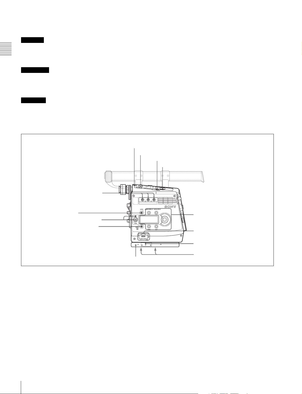
Front panel
a VF1 connector
b CONTROL PANEL connector
c Accessory receptacles
d VF2 connector
a VF1 (viewfinder 1) connector (20-pin)
Connect a viewfinder (optional).
b CONTROL PANEL connector
Connect with the CAMERA connector of the supplied
assistant panel (page 15).
c Accessory receptacles
Using these screw holes in combination with the accessory
pockets (page 11) on the left side, you can fix a certain
accessory to the left side of the camera.
e Viewfinder shoe
f Flange focal length adjustment screw
Lens mount
g Lens fixing lever
h Lens mount cap
i Shutter emergency open screw
f Flange focal length adjustment screw
You can adjust the flange focal length with the screw
behind the cover.
For details, see “Adjusting the flange focal length” (page
20).
g Lens fixing lever
Turn the lever clockwise to secure the lens in the lens
mount. To remove the lens, turn the lever
counterclockwise.
d VF2 (viewfinder 2) connector (20-pin)
Connect a second viewfinder (optional), e.g. for an
assistant.
Note
When two viewfinders are connected at the same time (via
the VF1 and VF2 connectors), if an HDVF-C950W is
connected to either connector, use an HDVF-C35W as the
other viewfinder. Because of a limitation of current
capacity, two HDVF-C950W viewfinders cannot be used
simultaneously.
e Viewfinder shoe
Attach an optional viewfinder.
The height of the attaching position can be adjusted.
For details, see “2-4 Attaching a Viewfinder” (page 21).
Locations and Functions of Parts
10
For details, see “2-3 Attaching a Lens” (page 20).
h Lens mount cap
Cover the lens mount with this cap when a lens is not
attached. The cover may be removed by rotating the lens
fixing lever counterclockwise.
i Shutter emergency opening screw
You can forcibly open the shutter in an emergency.
For details, see “To forcibly open the shutter” on page
109.
Page 11

Left panel
a Level vial
b L handle
c Accessory pockets
d DC IN connector
i DC OUT 12V connector
h (network) connector
g EXT I/O connector
f CAM POWER switch
e Power indicators
k Measure hook/focus
reference mark
j DC OUT 24V connector
Chapter 1 Overview
a Level vial
Used as a reference to check that the camera stands
horizontally. It can be fine-adjusted when required.
If fine-adjustment is required, remove the cover and adjust
it by rotating the three slotted-head screws.
b L handle
The L handle is attached to the top of the camera head at
the factory.
It has three screw holes (
3
/8") for accessories on the upper
side. The assistant panel (page 15) can be mounted on the
outside of the handle by attaching the supplied assistant
panel hanger.
c Accessory pockets
Using these accessory pockets in combination with the
accessory receptacles (page 10) on the front panel, you can
fix a certain accessory to the left side of the camera.
d DC IN connector (LEMO 8-pin)
Power is supplied by using a specified power cord.
e Power indicators
Either of the indicators lights according to the voltage of
the power being supplied.
f CAM POWER switch
CA: The camera is turned on using the power being
supplied via the interface box (page 15).
OFF: The power is cut off.
ON: The camera is turned on using the power being
supplied from the DC IN connector of the camera head.
Note
If you move the switch setting from ON to CA in one
stroke, the power may not be cut off. To turn off the power,
be sure to set the switch to the OFF position.
g EXT I/O (external control) connector (5-pin)
For control via RS-232C.
h (network) connector (RJ-45 type, 10BASE-T,
100BASE-TX)
For control from the MSU-900/950 Master Setup Unit, etc.
via a network cable.
Locations and Functions of Parts
11
Page 12
The necessary settings are made using the NETWORK
menu displayed on the viewfinder or monitor screen.
Buchse haben könnte. Folgen Sie den Anweisungen für
diese Buchse.
CAUTION
For safety, do not connect the connector for peripheral
device wiring that might have excessive voltage to this
Chapter 1 Overview
port. Follow the instructions for this port.
ATTENTION
Par mesure de sécurité, ne raccordez pas le connecteur
pour le câblage de périphériques pouvant avoir une tension
excessive à ce port. Suivez les instructions pour ce port.
ACHTUNG
Aus Sicherheitsgründen nicht mit einem PeripheriegerätAnschluss verbinden, der zu starke Spannung für diese
Right panel
i DC OUT 12V (DC 12V power output) connector
DC 12V power can be fed to an accessory.
j DC OUT 24V (DC 24V power output) connector
DC 24 V power can be fed to an accessory.
k Measure hook/focus reference mark
Use as reference for focusing. The same reference mark is
also provided at the right of the riser plate (page 13).
For actual measurement of the distance from a subject, you
can fix the end of a tape measure to the hook.
e Safety release tab
f Accessory clamp lever
g Lock release knob
h Accessory mount lever
a Assignable buttons 1, 2, 3
b LOCK switch
c RUN button and indicator
d 4/AUTO BLK BAL switch
Riser plate
a Assignable buttons 1, 2, 3
You can assign various functions to these buttons, using
the subdisplay on the left panel or on the assistant panel or
the menu displayed on the viewfinder or monitor screen.
The ND filter selection function is assigned to button 1 and
the CC filter selection function to button 2 at the factory.
(No function is assigned to button 3.)
For details, see “3-2-10 Allocation of Functions to the
Assignable Buttons and Switch” (page 35) and “3-7
Detailed Settings of the Switch Functions” (page 48).
b LOCK switch
To disable operations on the panel.
123
Display/menu operation block
(page 13)
i Memory stick section
j Focus reference mark
k Tripod receptacles (bottom)
You can make a setting to allow the RUN button to be
activated even when the LOCK switch is set to ON on the
<SUBDISPLAY 2> page on the USER (OPERATION)
menu.
c RUN button and indicator
To start/stop recording on the SRW-1 HD Portable Digital
Recorder docked on the camera. The indicator is lit while
the recorder is in Recording mode.
The indicator flashes as a warning in some cases.
For details on warning indication, see “Warning/Error
Messages” (page 108).
Locations and Functions of Parts
12
Page 13
The firmware of the SRW-1 may be required to be updated
for use with this camera. For details, consult your local
Sony representative.
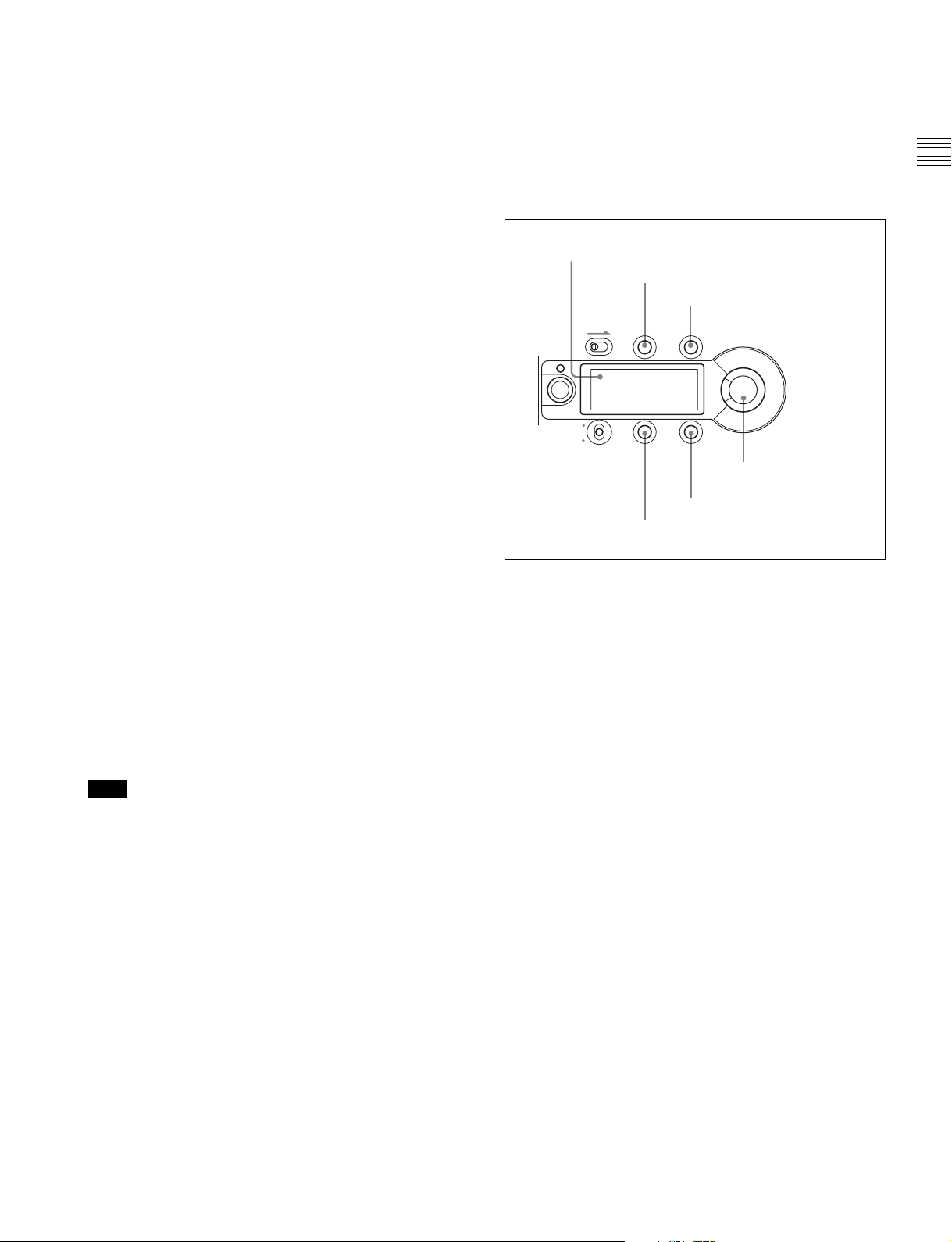
Display/menu operation block
Used to operate displays on the subdisplay and the
viewfinder/monitor screen.
d Assignable 4/AUTO BLK BAL (auto black balance)
switch
Push the switch downward to the AUTO BLK BAL side to
start the auto black balance adjustment.
The function activated by pressing the switch upward to
the 4 side can be selected using the subdisplay on the left
panel or on the assistant panel or the menu displayed on the
viewfinder or monitor screen.
For details, see “3-2-10 Allocation of Functions to the
Assignable Buttons and Switch” (page 35) and “3-7
Detailed Settings of the Switch Functions” (page 48).
e Safety release tab
f Accessory clamp lever
g Lock release knob
h Accessory mount lever
For mounting/unmounting an SRW-1 HD Portable Digital
Recorder or the supplied interface box to the top of the
camera head.
The mounting/unmounting mechanism is the same as that
on the rear panel (page 14).
For details, see “Chapter 2 Installation and
Preparations”.
i Memory Stick section
A slot to accommodate a “Memory Stick” is provided
behind the rubber cap.
The access lamp is lit in red while writing or reading data
to/from a “Memory Stick.”
You can use the “Memory Stick PRO” or “Memory Stick
PRO Duo” with this camera. The “Memory Stick PRO
Duo” media can be used without any adaptor.
Note
When the access lamp is lit in red, do not insert/remove the
“Memory Stick” or turn off the camera.
For details, see “5-3-1 Using a “Memory Stick”” (page
90).
j Focus reference mark
Used as a reference for focusing.
k Tripod receptacles (bottom)
Two screw holes (for
3
/8" camera screws) for tripod
mounting are provided.
For details on menu operations, see “3-2-1 Basic
Operation of the Subdisplay” (page 29) and “4-2 Basic
Menu Operations” (page 57).
a Subdisplay
b VF MENU/DISPLAY button
c CANCEL/STATUS button
LOCK
VF MENU/DISPLAY CANCEL/STATUS
RUN
4
AUTO
BLK
BAL
PAG E
SET
e SET button
d PAGE button
f MENU SEL/ENTER
dial
a Subdisplay
For basic settings of this camera.
When an SRW-1 HD Portable Digital Recorder has been
docked, some statuses of the recorder can also be
displayed.
When the supplied assistant panel is connected, the same
information will be displayed on the assistant panel.
b VF (viewfinder) MENU/DISPLAY button
Press this button to select the display mode of the
subdisplay and the viewfinder (monitor) screen.
c CANCEL/STATUS button
In Menu Operation mode, press this button to cancel your
entry or to resume the previous status.
If you press this button when the menu is not displayed on
the viewfinder (monitor) screen, the status information of
the camera will be displayed.
For the information displayed, see “3-6 Viewing and
Setting the Viewfinder Displays” (page 43).
d PAGE button
Press this button to flip the pages or register the setting on
the subdisplay.
Chapter 1 Overview
e SET button
The subdisplay enters Data Change mode if you hold this
button pressed for more than 1 second. Use this button also
to flip to the previous page on the subdisplay.
Locations and Functions of Parts
13
Page 14
f MENU SEL (selection) /ENTER dial
Used to select or set the items on the subdisplay or the
menu items on the viewfinder (monitor) screen.
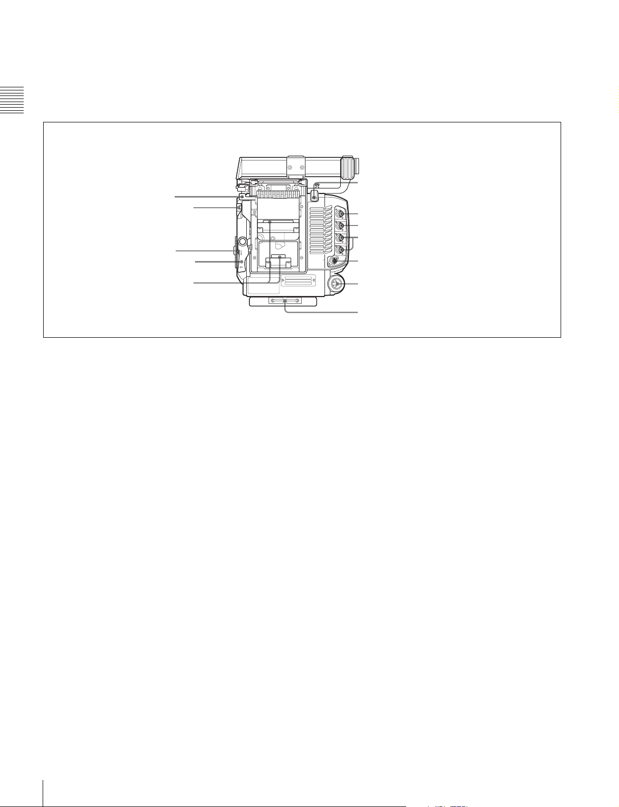
Rear panel
Chapter 1 Overview
a Safety release tab
b Accessory clamp lever
c Lock release knob
d Accessory mount lever
23
OFFON
REMOTE
f RUN indicator and ON/OFF switch
g GENLOCK IN connector
h TEST OUT connector
i MONITOR OUT HD SDI connectors 1/2
j REMOTE connector
e Recorder/interface box
receptacles
a Safety release tab
b Accessory clamp lever
c Lock release knob
d Accessory mount lever
For mounting/unmounting an SRW-1 HD Portable Digital
Recorder or the interface box to/from the rear of the
camera head.
The mounting/unmounting mechanism is the same as that
on the top (page 13).
For details, see “Chapter 2 Installation and
Preparations”.
e Recorder/interface box receptacles
Signals and power are sent/received to/from an SRW-1 HD
Portable Digital Recorder or the supplied interface box
(page 15) mounted on the rear.
The same receptacles are provided on the top to send/
receive signals and power to/from the recorder or the
interface box mounted on the top.
When using a rechargeable battery
Use the receptacles on the rear panel. By attaching the
BKP-L551 to the rear of the interface box, the camera can
be operated on a battery. Note, however, that power will be
fed only to the camera head and viewfinder. Provide
another power source for the recorder.
DC IN connector (see page 11)
k Wrench box
g GENLOCK IN (external sync signal input)
connector (BNC type)
Used for input of an external gen-lock signal (HD 3-level
sync).
h TEST OUT connector (BNC type)
An analog test signal is fed from the connector.
The type of output signal can be set using a menu on the
viewfinder or monitor screen.
i MONITOR OUT HD SDI connectors 1/2 (BNC
type)
An HD SDI signal for monitoring is fed from the
connectors.
The type of output signal can be set using a menu on the
viewfinder or monitor screen.
The same signal is output from connector 1 and 2.
j REMOTE connector (8-pin)
Connect an external control device, such as the RM-B150/
B750 Remote Control Unit.
k Wrench box
A 3-mm wrench for attaching/detaching the handle and a
2.5-mm wrench for attaching/detaching the viewfinder
shoe are accommodated.
f RUN indicator and ON/OFF switch
When the switch is set to ON, the indicator will be lit while
the recorder mounted on the camera is in Recording mode.
Locations and Functions of Parts
14
Page 15
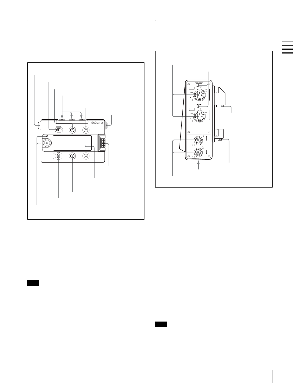
1-3-2 Assistant Panel (Supplied)
1-3-3 Interface Box (Supplied)
The most parts are common to those on the right panel of
the camera head. Connecting the panel to the CONTROL
PANEL connector (page 10) of the camera head permits
the camera and recorder to be operated at hand.
a CAMERA connector
LOCK switch
VF MENU/DISPLAY button
Assignable buttons 1, 2, 3
CANCEL/STATUS button
b AUX connector
LOCK VF MENU/DISPLAY CANCEL/STATUS
MENU SEL/
ENTER
RUN
4
AUTO
BLK BAL
4/AUTO BLK BAL switch
RUN button and indicator
PAG E
SET
SET button
PAG E bu t t on
MENU SEL/ENTER
dial
Subdisplay
Being attached to the top or the rear of the camera head, it
transfers signals and power to/from the camera head.
a AUDIO IN CH-1/CH-2 connectors
b Audio input selection switches
LINE MIC
+48V ON
CH-1
LINE MIC
+48V ON
CH-2
A
B
c HD-SDI A/B connectors
AUDIO IN
e Camera connector 1
HD-SDI
f Camera connector 2
d DC IN connector (bottom)
a AUDIO IN CH-1/CH-2 connectors (XLR 3-pin,
female)
Connect audio signals. Each connector is equipped with an
input selection switch.
Chapter 1 Overview
a CAMERA connector
Using the supplied assistant panel cable, connect to the
CONTROL PANEL connector of the camera head.
b AUX (auxiliary) connector
Connect to an external device as required.
The other parts function the same as those on the right side
panel of the camera head.
Note
If the assistant panel cable is disconnected/connected
while you are operating the subdisplay or a menu on the
viewfinder/monitor screen, the cursor/pointer on the
subdisplay or on the menu page may inadvertently be
moved. If a ? symbol is shown on the display, first register
the setting, then disconnect/connect the cable.
b Audio input selection switches
Set to the appropriate position according to the equipment
connected to the corresponding AUDIO IN connector.
LINE: When a line-level (+4 dBu) signal source is
connected
MIC: When an external microphone is connected (No
power is supplied.)
+48 V ON: To supply power of +48 V to the connected
microphone
c HD-SDI A/B connectors
For Dual Link outputs of an HD-SDI signal.
d DC IN connector (XLR 4-pin)
Connecting the BKP-L551 Battery Adaptor or a specified
power cable, supply power to the interface box. The power
is also fed to the camera head, viewfinder, and lens.
Note
Power is not fed to an SRW-1 recorder.
Locations and Functions of Parts
15
Page 16

e Camera connector 1
When the interface box is mounted on the top or rear of the
camera head, video/audio and control signals are sent/
received to/from the camera head.
f Camera connector 2
Chapter 1 Overview
When the interface box is mounted on rear of the camera
head, power is sent/received to/from the camera head.
Locations and Functions of Parts
16
Page 17
Installation and
Preparations
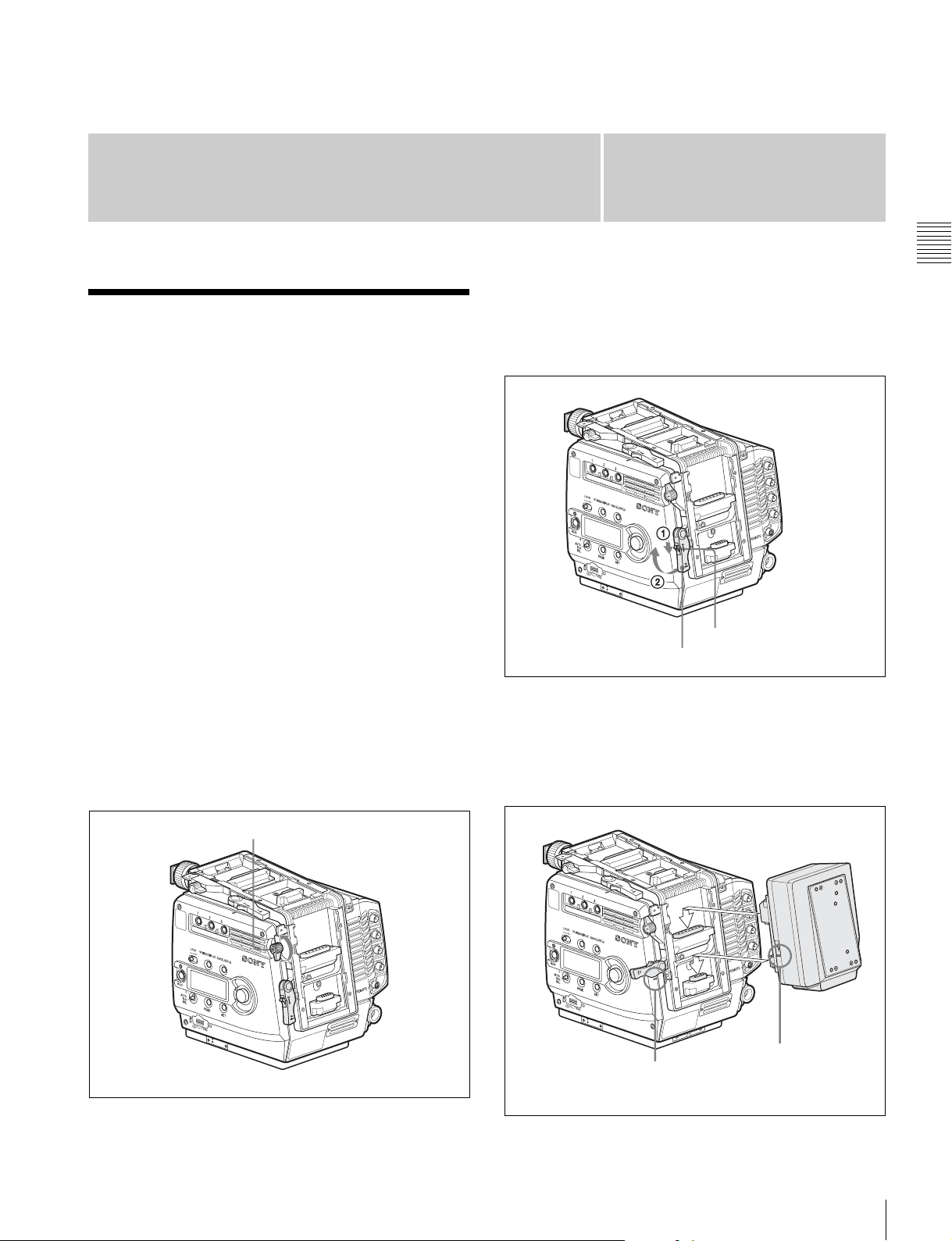
2-1 Mounting the Interface Box
The supplied interface box can be attached to the top or
rear of the camera head.
Connection between the camera head and the interface box
is achieved by mounting, eliminating additional cable
connections.
• The same attaching/detaching system is used both on the
top and the rear.
• The following instructions use the illustrations of
attaching to the rear as examples.
• Although the illustrations show the statuses where the L
handle has been detached, the interface box can be
mounted/unmounted with the L handle attached.
Chapter
3
Release the lock by sliding the lock-release knob in the
direction of the arrow (1 in the figure below) then pull
up the accessory mount lever (pull it toward the lens
when mounting on the top) (2 in the figure below).
Accessory mount lever
2
Lock-release knob
Chapter 2 Installation and Preparations
To attach
1
Place the camera head on a stable, flat surface.
2
Rotate the accessory clamp lever upward (toward the
lens when attaching to the top).
Accessory clamp lever
4
Aligning the matching line on the interface box with
that on the camera head, fit the interface box into the
camera head then push down on the box (slide it in the
opposite direction of the lens when attaching to the
top) so that the connectors engage.
Matching line on
Matching line on
the camera head
the interface box
Mounting the Interface Box
17
Page 18
Chapter 2 Installation and Preparations
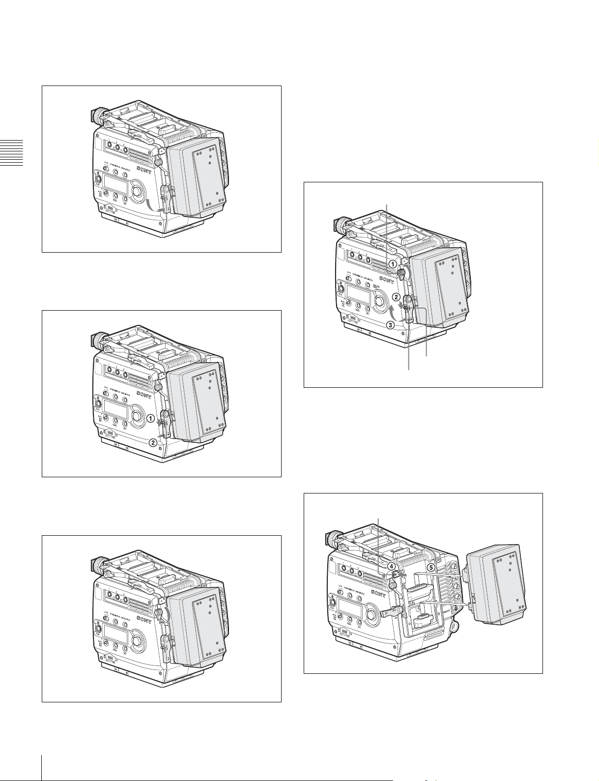
5
Rotate the accessory mount lever downward (pull it in
the opposite direction of the lens when attaching to the
top).
6
While holding the lock-release knob in the direction of
the arrow, fold the accessory mount lever into its home
position.
To detach
1
Rotate the accessory clamp lever upward (toward the
lens when attaching to the top) (1 in the figure
below).
2
Release the lock by sliding the lock-release knob in the
direction of the arrow (2 in the figure below) then pull
up on the accessory mount lever (3 in the figure
below) (pull it toward the lens when mounting on the
top).
Accessory clamp lever
7
Rotate the accessory clamp lever downward (toward
the opposite direction of the lens when attaching to the
top).
Lock-release knob
Accessory mount lever
3
While holding the safety release tab pressed inward,
pull up on the interface box to disengage the
connectors, then pull out the box horizontally.
(When attaching to the top, hold the safety release tab
pressed downward, slide the interface box toward the
lens to disengage the connectors, then pull out the box
vertically).
Safety release tab
Mounting the Interface Box
18
4
Return the accessory mount lever and accessory clamp
lever to their home positions.
Page 19
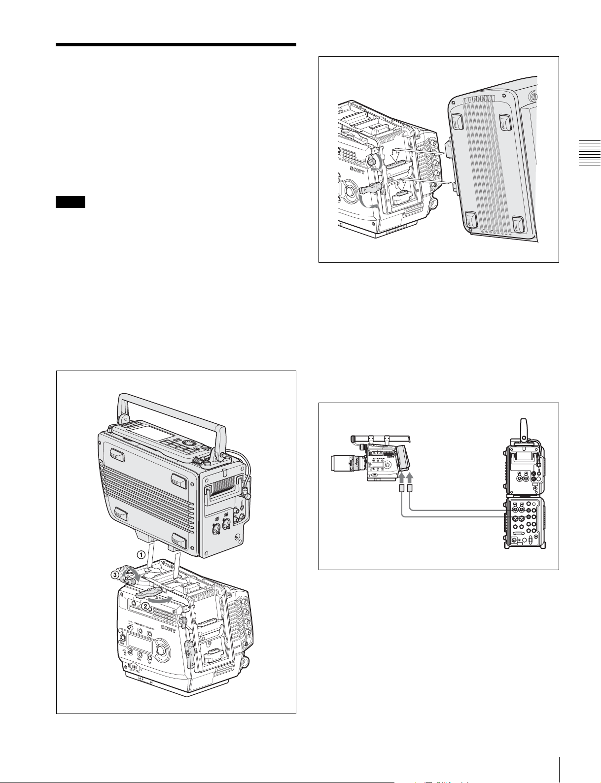
2-2 Mounting the SRW-1 Recorder
Mounting to the rear
SRW-1
In the same manner as the interface box, the SRW-1 HD
Portable Digital Recorder can be mounted on the top or
rear of the camera head.
For handling of the SRW-1 Recorder, refer to the Operation
Manual of the recorder.
Notes
• The firmware of the SRW-1 may be required to be
updated for use with the camera.
For details, consult your Sony representative.
• When mounting the recorder, fix the camera head on a
tripod in advance to keep the camera head stable.
For tripod mounting, see “2-5 Mounting the Camera to
a Tripod” (page 22).
• When the camera is to be used with the recorder
mounted, make sure that the camera is securely fixed and
stable so that it will not topple over or fall.
Mounting to the top
SRW-1
N
O
1
C
K
VF MENU/DISPLAY CANCEL/STA
2
3
3
TUS
P
A
G
E
S
E
T
P
R
O
2
1
OFF
E
T
O
M
E
R
When connecting the SRW-1 recorder
using cables
Attach the SRPC-1 HD Video Processor to the recorder to
permit cable connections to the interface box mounted on
the camera.
Use two coaxial cables for connections. The cable length
can be extended up to 100 m when 5C-FB cables are used.
The camera and recorder must be controlled independently
when connected via cables.
Chapter 2 Installation and Preparations
Coaxial cables
SRW-1
HD SDI AHD SDI B
HD SDI IN A
HD SDI IN B
SRPC-1
Mounting the SRW-1 Recorder
19
Page 20
2-3 Attaching a Lens
60
oo
5
.6
8
11
16
C
L
2.8
2
1.6
T
ff
4
30
20
1
5
1
2
10
Attach an appropriate optional lens that conforms to the PL
lens mount.
Note
Always use a lens whose projection from the flange (A in
the figure) is less than 30 mm. Use of any lens that
Chapter 2 Installation and Preparations
protrudes more tha 30 mm will damage the internal filter.
For information on handling lenses, refer to the lens’
operation manual.
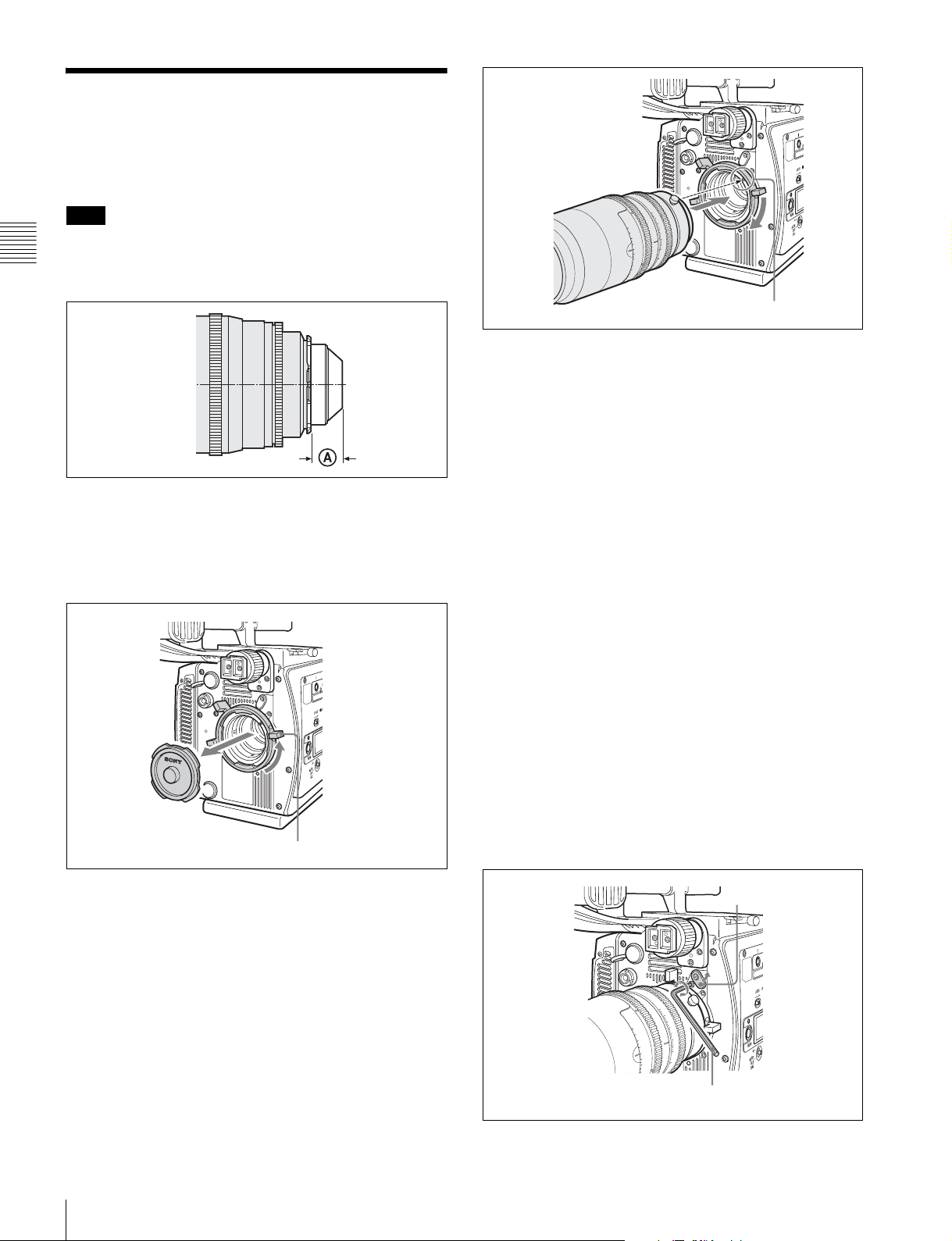
1
Rotate the lens fixing lever counterclockwise and
remove the lens mount cap from the lens mount.
T
1.6
2
ff
2.8
4
oo
60
5.6
0
3
8
0
2
11
15
6
1
12
L
0
C
1
8
7
6
5.6
5
Notch
Selecting a lens file
With this camera, values, such as the compensation values,
which are specific to the mounted lens can be registered in
a lens file. You can perform necessary adjustments upon
replacement of lenses by merely invoking the registered
file.
Select the file using the subdisplay.
For lens file selection on the subdisplay, see “3-2-6
Selection of a Lens File” (page 34).
For details on the lens files, see “5-1 File Configuration”
(page 87).
Lens fixing lever
2
Align the lens’ alignment pin with the notch in the
upper part of the lens mount and insert the lens (sold
separately) into the mount.
3
While supporting the lens, rotate the lens fixing lever
clockwise to secure the lens.
Adjusting the flange focal length
Adjustment of the flange focal length (distance between
the lens mount attachment plane and the imaging plane) is
necessary in the following situations:
• The first time a lens is attached
• When changing lenses
• If the focus is not sharp at both telephoto and wide angle
when zooming
The flange focal length for this camera can be adjusted by
rotating the adjustment screw on the front panel.
Use an Allen wrench (7/64” diagonal):
Cover
20
Attaching a Lens
Allen wrench
Page 21
1
Loosen the fixing screw using a screwdriver, then open
the cover.
2
Rotate the adjustment screw using an Allen wrench.
Clockwise rotation lengthens the flange focal length,
and counterclockwise rotation shortens it.
Remember as a guide that ±3 turns of the screw
correspond to variation of the flange focal length of
±0.15 mm.
When the adjustment is finished, close the cover and
tighten the fixing screw.
2-4 Attaching a Viewfinder
Caution
When the viewfinder is attached, do not leave the camera
with the eyepiece facing the sun. Direct sunlight can enter
through the eyepiece, be focused in the viewfinder and
cause fire.
For details on the viewfinder, refer to the instruction
manual of the viewfinder.
If the viewfinder must be attached lower
Loosen the two screws, using the 2.5-mm wrench stored in
the wrench box (page 14) to detach the viewfinder shoe,
and attach it to the lower position using the lower screw
holes.
Chapter 2 Installation and Preparations
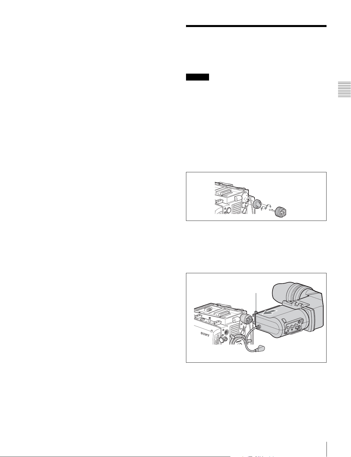
Attaching procedure
1
Fit the viewfinder to the viewfinder shoe and slide the
viewfinder horizontally.
The viewfinder stopper automatically pops down.
Stopper
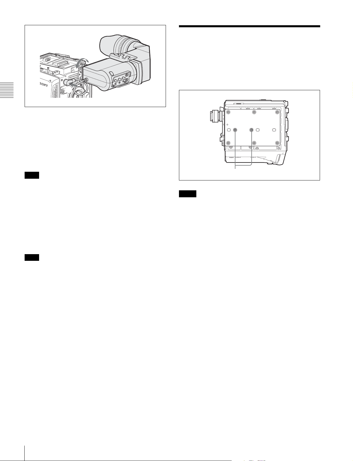
2
Set the viewfinder to the most convenient position,
tighten the viewfinder positioning ring (1 in the
figure below), and connect the viewfinder cable to the
VF1 connector of the camera (2 in the figure below).
Attaching a Viewfinder
21
Page 22
2-5 Mounting the Camera
1
1
F
V
L
R
2
T
C
Chapter 2 Installation and Preparations
When the supplied center handle is attached to the top of
the camera head, you can attach the viewfinder to the
viewfinder shoe of the center handle. In this case, first
remove the viewfinder shoe from the camera head.
For details on the center handle, see “2-6-2 Center Handle
(Supplied)” (page 23).
Note
When the L handle is attached to the camera head, the
attaching condition may be limited, owing to the
viewfinder position and the rotating position of the hood.
When the second viewfinder is required
Connect it to the VF2 connector.
Using the menus, you can specify the display condition
independently of the viewfinder connected to the VF1
connector.
to a Tripod
Two tripod receptacles (for 3/8” camera screws) are
provided on the bottom of the camera head.
Tripod receptacles
Notes
• Select an appropriate hole, considering the balance of the
weight of the camera. If an inappropriate hole is selected,
the camera may fall over.
• Check that the size of the selected hole matches that of
the screw of the tripod. If they do not match, the camera
cannot be attached to the tripod securely.
Note
When two viewfinders are connected at the same time (via
the VF1 and VF2 connectors), if an HDVF-C950W is
connected to either connector, use an HDVF-C35W as the
other viewfinder. Because of a limitation of current
capacity, two HDVF-C950W viewfinders cannot be used
simultaneously.
To detach the viewfinder
Loosen the viewfinder positioning ring, pull on the
viewfinder stopper, then pull out the viewfinder by sliding
it in the direction opposite that when attaching.
Mounting the Camera to a Tripod
22
Page 23
2-6 Attaching/Detaching Handles
2-6-1 L Handle
The L handle is attached to the top of the camera head at
the factory.
Three screw holes (for
the upper side of the L handle can be used for fixing
various accessories.
Mounting the assistant panel
By attaching the supplied assistant panel hanger, you can
mount the assistant panel on the outside of the handle.
3
/8” camera screws for a tripod) on
Assistant panel
hanger (supplied)
2
3
R
U
N
O
F
F
O
N
N
I
K
C
O
L
N
E
2
G
T
U
O
T
S
E
T
Hex-head screws
To attach the handle in the original position, reverse the
procedure for detaching.
2-6-2 Center Handle (Supplied)
The supplied center handle can be attached to the top or
rear of the camera head.
Attach it so that the slanting side faces the back (or
bottom).
The screw holes on the upper side of the handle can be used
for fixing various accessories.
Chapter 2 Installation and Preparations
four +B4×8 screws (supplied)
2
3
R
U
N
O
F
F
O
N
N
I
K
C
O
L
N
E
2
G
T
U
O
T
S
E
T
Assistant panel
Detaching the L handle
If the L handle is not necessary or to be replaced with the
supplied center handle, remove it by loosening the two
screws, using the 3-mm wrench stored in the wrench box
(page 14).
Attaching the handle directly to the camera
head
The handle can be attached/detached in the same manner
as the interface box (see page 17).
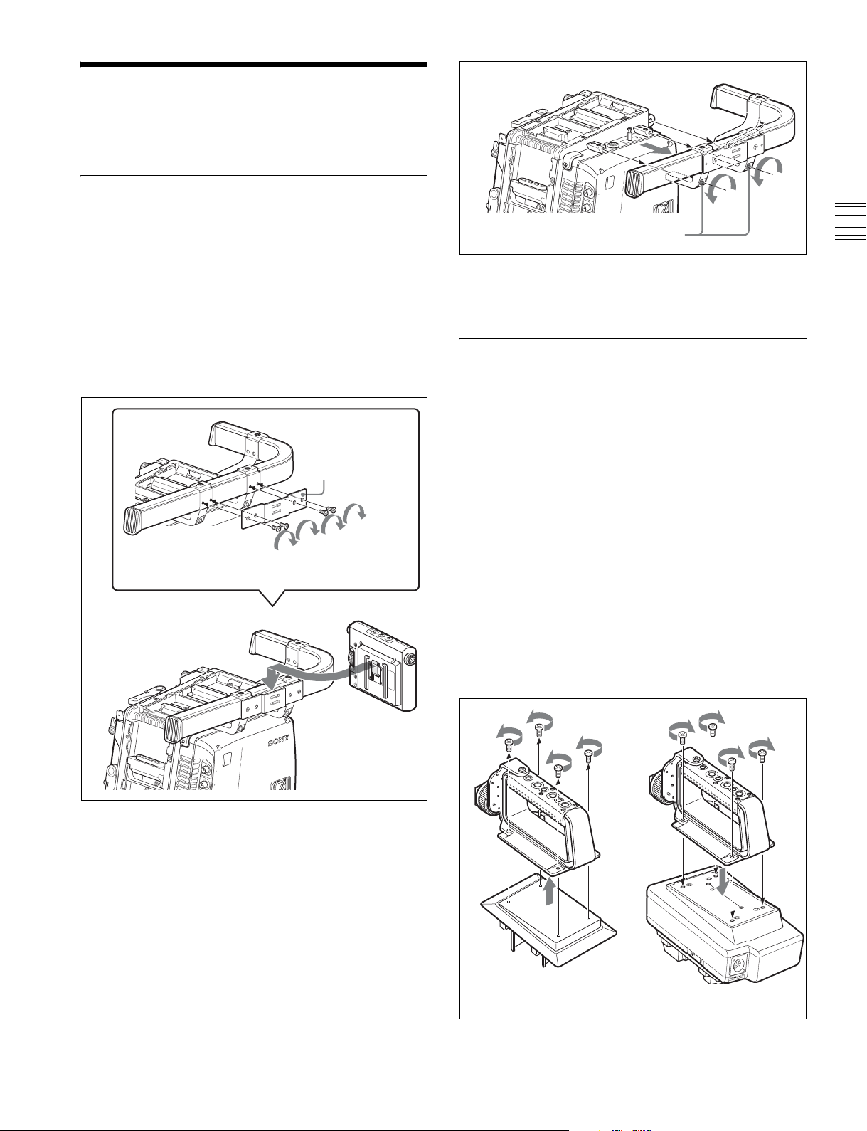
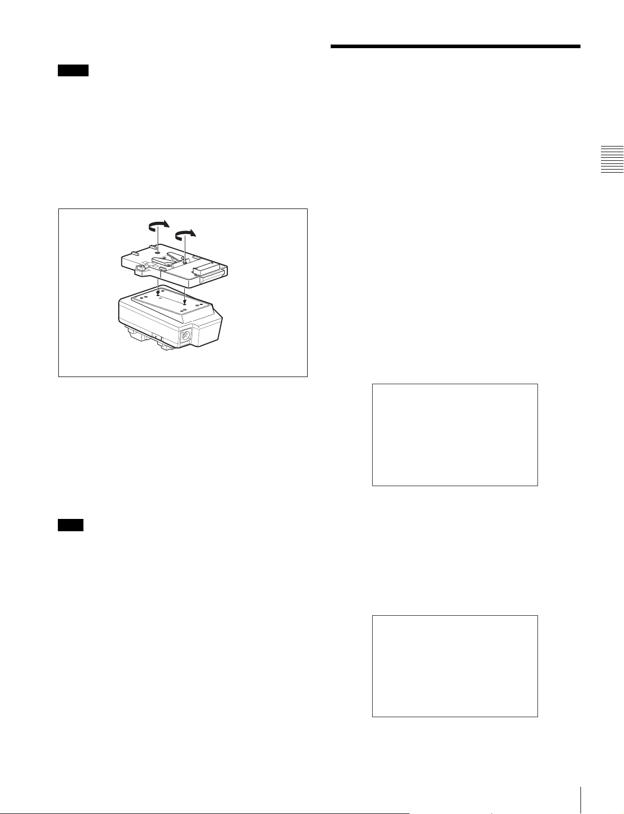
Attaching the handle to the interface box
mounted on the camera head
First remove the base plate from the handle by loosening
the four screws, then attach it to the interface box.
12
Base plate
Interface box
Attaching/Detaching Handles
23
Page 24

Attaching a viewfinder
When the supplied center handle is attached to the top of
the camera head, you can attach the viewfinder to the
viewfinder shoe of the center handle after removing the
viewfinder shoe from the camera head.
The procedure for attaching the viewfinder is the same as
when attaching it to the viewfinder shoe of the camera head
(see page 21).
Chapter 2 Installation and Preparations
2-7 Preparing the Power Supply
This camera operates on DC 12 V (10.5 to 17 V).
Supplying power directly to the camera
head
Connect a power supply to the DC IN connector of the
camera head.
Use a commercially available shielded cable by attaching
the supplied 8-pin connector for a power cable.
For details on the connection, consult your local Sony
representative.
To turn on the camera
Set the CAM POWER switch of the camera head to the ON
side, and the camera is turned on.
Power is also supplied to the viewfinder and lens mounted
on the camera head.
Power of 12 V or 24 V can be fed to accessories via the DC
OUT connectors.
Supplying power via the interface box
To supply power via the interface box, mount the interface
box to the rear of the camera head. If the interface box is
mounted on the top, the power is not fed to the camera
head.
Connect a power supply to the DC IN connector (XLR 4pin) of the interface box.
To turn on the camera
Set the CAM POWER switch of the camera head to the CA
side, and the camera is turned on.
The power is also supplied to the viewfinder and lens
mounted on the camera head.
To use an AC power source
An AC power source can be connected, by using the ACDN2B AC Adaptor.
1
Attach the AC-DN2B to the interface box.
2
Connect the DC power cord supplied with the ACDN2B to the DC IN connector of the interface box.
3
Connect the AC-DN2B to an AC power source.
Preparing the Power Supply
24
To use a battery pack
The BP-GL95 Lithium-ion Battery Pack can be used.
By attaching the BKP-L551 Battery Adaptor to the
interface box, connect the BP-GL95 Lithium-ion Battery
Page 25
Pack to the interface box.
Notes
• Remove the battery pack if the camera will be out of use
for an extended period.
• Charge the battery, using the specified battery charger,
before use.
For charging, refer to the instructions for the battery
charger.
1
Attach the BKP-L551 Battery Adaptor to the interface
box.
BKP-L551
LO
C
K
Interface box
V
7
-1
V
.5
0
1
IN
C
D
2-8 Setting the Built-in Clock
When using the camera for the first time, set the built-in
clock to the local time, using the <DATE> page of the
MAINTENANCE menu displayed on the viewfinder
screen.
To set the menu on monitor screen, connect a monitor to
either of the MONITOR OUT HD SDI connectors.
Setting procedure
1
Turn on the camera.
2
While holding the MENU SEL/ENTER dial pressed,
press the VF MENU/DISPLAY button.
The camera enters Menu Operation mode, and “TOP”
is displayed at the upper-right corner of the screen.
3
Rotate the MENU SEL/ENTER dial to set the pointer
to “TOP” and push on the MENU SEL/ENTER dial.
The TOP MENU screen is displayed.
Chapter 2 Installation and Preparations
2
Aligning the groove on the BP-GL95 with the
projection on the BKP-L551, slide the BP-GL95 so
that the connectors engage.
3
Connect the DC cable of the BKP-L551 to the DC IN
connector of the interface box.
When the battery is connected to the DC IN connector of
the interface box, power is fed to the camera head,
viewfinder, and lens.
Note
Power is not supplied to the recorder mounted on the
camera head. To supply power to the recorder, connect a
power supply to the DC IN connector on the camera head.
<TOP MENU>
B
USER
USER MENU CUSTOMIZE
ALL
z
OPERATION
z
PAINT
z
MAINTENANCE
z
NETWORK
z
FILE
z
DIAGNOSIS
4
Rotate the MENU SEL/ENTER dial to position the
pointer to MAINTENANCE and push on the MENU
SEL/ENTER dial.
The CONTENTS page of the MAINTENANCE menu
is displayed.
(The following display examples are those in Custom
mode. They include some items not displayed in Cine
mode.)
CONTENTS M00
xx
B
01.<BASE SETTING>
02.<AUTO SETUP>
03.<WHITE SHADING>
04.<BLACK SHADING>
05.<OHB MATRIX>
06.<AUDIO>
07.<OUTPUT FORMAT>
08.<DOWN CONVERTER>
09.<POWER SAVE>
10.<BATTERY ALARM SET>
5
Turn the MENU SEL/ENTER dial to scroll the page
and position the pointer to <DATE>.
Setting the Built-in Clock
25
Page 26

Chapter 2 Installation and Preparations
CONTENTS M00
xx
02.<AUTO SETUP>
03.<WHITE SHADING>
04.<BLACK SHADING>
05.<OHB MATRIX>
06.<AUDIO>
07.<OUTPUT FORMAT>
08.<DOWN CONVERTER>
09.<POWER SAVE>
10.<BATTERY ALARM SET>
B
11.<DATE>
6
Push on the MENU SEL/ENTER dial.
The <DATE> page is displayed.
<DATE> M12 TOP
DATE/TIME
x
2008/3/22 16:53
7
Turn the MENU SEL/ENTER dial and set the date and
time.
Push on the MENU SEL/ENTER dial to shift to the
next digit.
8
When the date/time setting is completed, press the VF
MENU/DISPLAY button to exit Menu Operation
mode.
For details on menu operations, see “4-2 Basic Menu
Operations” (page 57).
Setting the Built-in Clock
26
Page 27

Basic Adjustments and
Settings
3-1 Selection of the Basic Operation Modes
3-1-1 Overview of the Basic Operation Modes
With this camera, Cine mode and Custom mode can be
switched. Cine mode is designed for shooting the materials
that will undergo post-production editing and that do not
need on-set grading, as with shooting with a film camera.
Custom mode is designed for shooting with all the setting
items of the camera set as you wish.
The items that can be set and the selectable values on the
menus and from the remote control unit are different in
Cine mode and Custom mode.
Chapter
Custom mode
• This mode is designed for shooting with detailed settings
on the menus or with operations from the remote control
unit.
• The reference file, which stores the values to be used as
reference for adjustments, and the scene files, which
store the adjustment values specific to a particular scene,
are available in this mode.
• User Gamma can be installed.
• Modification and storage of the lens files are possible.
Note
The settings for the file items adjusted in Custom mode are
maintained when the camera is switched back to Cine
mode. However, the video adjustment values that are
temporarily changed and not stored in any file will be
cleared upon mode switching.
For details on different items and values that can be set in
each mode, see “4-3 Menu List” (page 60).
3
Chapter 3 Basic Adjustments and Settings
Cine mode (default mode)
• The subdisplay and the USER menu are mainly used.
• The items related to image creation are fixed at the
factory-set values, and menu displays are simplified.
• Only auto black balance (ABB) can be activated as auto
setup.
The white balance level is fixed at the preset value
(3200K), and auto white balance (AWB) and WHITE R/
G/B settings are not operative.
• On a remote control unit connected to the REMOTE
connector of the camera, the values for the adjustment
items whose settings fixed in Cine mode are not
displayed. However, data for the ON/OFF setting items
and selectable items are displayed although they are
fixed in Cine mode.
• Reading/writing of files from/to a “Memory Stick” and
data presetting are enabled only for the operator file that
is included in the USER menu.
• Only retrieval by specifying a file number is allowed
among the lens file operations.
• The reference file items are fixed to the default values set
at the factory even if you have changed the values in
Custom mode.
3-1-2 Switching of the Basic Operation Modes
At shipment, Cine mode is selected.
To switch to Custom mode
Referring to the procedures described in “2-8 Setting the
Built-in Clock” (page 25), call up the <BASE SETTING>
page of the MAINTENANCE menu on the viewfinder
screen or the monitor screen and switch the modes.
On the same page, making settings for dynamic range and
color space is also possible.
Selection of the Basic Operation Modes
27
Page 28

<BASE SETTING> page of the MAINTENANCE
menu
<BASE SETTING> M01 TOP
B
SHOOT MODE :
D-RANGE : EXTEND
COLOR SPACE: S-GAMUT
CUSTOM
SHOOT MODE
Switch between CINE and CUSTOM on this line.
Chapter 3 Basic Adjustments and Settings
D-RANGE
With EXTEND, the dynamic range and sensitivity are
improved. The S/N ratio is improved with NORMAL.
COLOR SPACE
Select color reproducibility:
S-GAMUT: This mode enables you to record with wider
color space than with the conventional cameras (HDCF950, HDW-F900R, etc.) whose color space is
equivalent to that available with film cameras.
With postproduction processes, color expression can be
substantially extended.
For details on reproducible gamuts, see “Color Space
According to the COLOR SPACE Settings” (page 117).
Note
Images shot with the S-GAMUT setting will be seen in
somewhat pale colors if they are reproduced on a
conventional narrow color-space display, such as a
CRT display.
F900: This mode enables you to shoot with color space
equivalent to that available with conventional cameras.
This facilitates color matching with conventional
cameras. Furthermore, as wider color-space data
available with this camera can be used without
restriction, distinguishability of images with higher
color saturation will be improved over that with
conventional cameras.
F900R: This mode enables you to shoot with color space
as close as possible to that of the HDW-F900R, by
limiting the color space to that of the HDW-F900R.
When using this camera in combination with the HDWF900R, use this mode for easy color matching.
Note
This mode can be selected only when “COLOR
F900R” is set to “ENABLE” on the <OTHERS 2> page
of the MAINTENANCE menu.
DCDM REF PJ: This mode enables color reproducibility
that is recommended by the Digital Cinema Initiatives
(DCI). The camera can output signals for display
devices that can reproduce this color space, such as a
DLP projector.
If a video production is to be displayed on a device that
complies with the DCI standards, shooting in this mode
will minimize the necessity for postproduction
processes, such as color correction.
For details on menu operations, see “4-2 Basic Menu
Operations” (page 57).
Selection of the Basic Operation Modes
28
Page 29
3-2 Basic Settings with the Subdisplay
However, the LOCK switches disable the buttons and dial
on their own sides. To inhibit operations on either side, set
the LOCK switch on the side to be inhibited to ON.
Turning the MENU SEL/ENTER dial can change a setting,
and pressing on it can register (ENTER) a setting.
Basic settings of the camera can be easily performed, using
the subdisplay located on the side of the camera or that of
the assistant panel if connected via the CONTROL PANEL
connector of the camera.
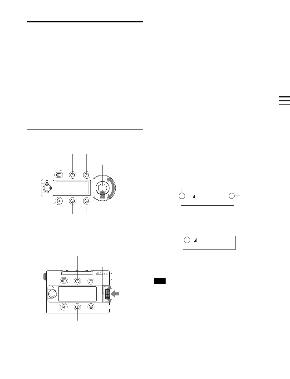
3-2-1 Basic Operation of the Subdisplay
For operation of the subdisplay, the buttons and dial shown
in the figures below are used:
Side panel of the camera head
VF MENU/DISPLAY button
(For registering a setting)
LOCK
VF MENU/DISPLAY CANCEL/STATUS
RUN
4
AUTO
BLK
BAL
PAGE button
(For advancing
pages/registering a
setting)
CANCEL/STATUS button
(For canceling of a setting)
MENU SEL/ENTER dial
PAG E
Press
SET
(For determining a setting)
SET button
(For reversing pages/entering
Data Change mode by holding
the button pressed for 1 sec)
Tu r n
(For changing
a setting)
To display the Setting pages
After the camera is turned on, the selected operation mode
(CINE or CUSTOM) is displayed on the subdisplay for
several seconds, after which the Setting page that was
operated last time is displayed.
To advance to the next page
Press the PAGE button.
To go back to the previous page
Press the SET button (press and release the button within 1
second).
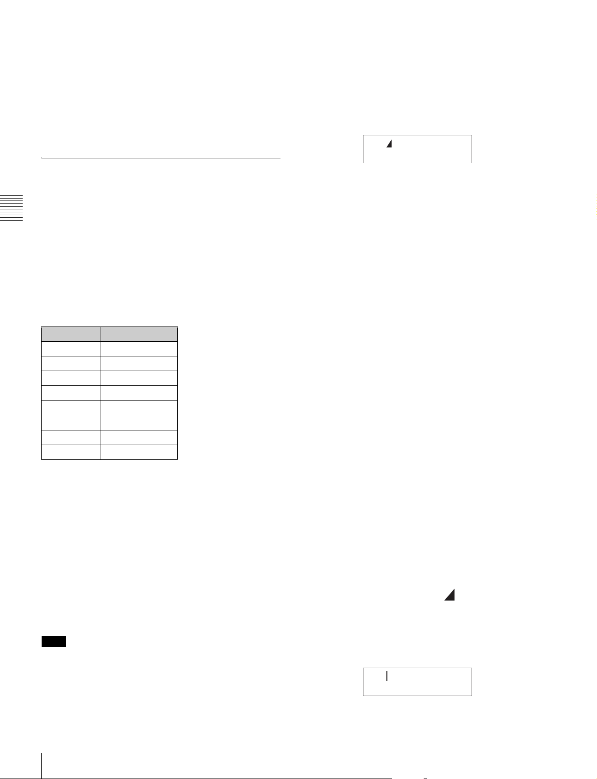
To change a setting
Press and hold the SET button for more than 1 second.
Data Change mode is entered, the cursor ( | ) starts
flashing, and the question mark (? symbol) appears at the
rightmost position on the first line.
Cursor (flashing)
S C 3 6 0 . 0 O N ?
2
4 F P S C M P : O F
On a page with two or more setting items, each time the
SET button is pressed, the cursor moves to the next item.
Cursor
Question mark
F
Chapter 3 Basic Adjustments and Settings
Assistant panel
VF MENU/DISPLAY button CANCEL/STATUS button
MENU SEL/
ENTER dial
LOCK VF MENU/DISPLAY CANCEL/STATUS
MENU SEL/
ENTER
Press
RUN
4
AUTO
BLK BAL
PAGE button
PAG E
SET
SET button
Tu r n.
Operations of the subdisplay are possible with the buttons
and dial both sides of the camera and assistant panel.
S C 3 6 0 . 0 O N ?
2
4 F P S C M P : O F
F
Move the cursor to the item you wish to modify then
change the setting by turning the MENU SEL/ENTER
dial.
Note
While the subdisplay is in Data Change mode, menu
operations on the viewfinder cannot be performed.
To determine a changed setting
Perform one of the following:
• Press the PAGE button.
• Exit Data Change mode by pressing the MENU SEL/
ENTER dial (the cursor and question mark disappear).
• Terminate the subdisplay operation by pressing the VF
MENU/DISPLAY button.
Basic Settings with the Subdisplay
29
Page 30
To cancel a change on a setting
Without registering a change of a setting, press the
CANCEL/STATUS button. The question mark disappears,
and the original setting is restored.
To terminate subdisplay operation
Press the VF MENU/DISPLAY button.
3-2-2 Shutter Settings
the remote control unit correctly, upgrading of the version
is required.
For details, consult your local Sony representative.
Shutter setting page
123
S C 3 6 0 . 0 O N
2
4 F P S C M P : O F
45
F
The electronic shutter of this camera can be adjusted, with
settings displayed in shutter angles, as with a film camera,
in addition to exposure time.
Chapter 3 Basic Adjustments and Settings
Two operation methods are available for the adjustment:
stepwise and continuous.
Step mode
Your frequently used shutter values (8 values at maximum)
can be registered, enabling stepwise selection of the
shutter values.
At shipment, the following values are registered:
STEP No. Shutter angle
1 216.0º
2 180.0º
3 172.8º
4 150.0º
5 144.0º
6 90.0º
7 45.0º
8 22.5º
To select a shutter value step by step
In Step mode, one of the registered shutter values (8 values
at maximum) can be selected, as follows:
1
Move the cursor to the left of “S” at 1.
(Immediately after the shutter setting page is switched
to Setting Change mode, the cursor is always
displayed at the left of “S”.)
2
Display the shutter angle you wish to use at 2 by
turning the MENU SEL/ENTER dial.
The eight registered values for shutter angle will be
displayed one after another as the MENU SEL/
ENTER dial is turned.
To select an arbitrary shutter value
To use a shutter value that is not registered as a step shutter
value, use Continuous mode.
1
Press the SET button to move the cursor to the left of
“C” at
1.
The corresponding shutter speeds vary according to the
frame frequency and frame rate of the selected video
format. The step shutter values can be changed and reregistered on the <SHUTTER ASSIGN> page of the
USER (OPERATION) menu or the <SHUTTER/FPS>
page of the USER (PAINT) menu.
Continuous mode (ECS)
The shutter values can be continuously changed in a range
from 360.0 to 4.3 degrees.
To obtain your desired shutter value quickly, assign a value
nearest your desired one in Step mode, switch to
Continuous mode, then adjust the shutter value.
Note
In a case where a remote control unit connected to the
REMOTE connector of the camera is used, adjustment in
Step mode is enabled with SHUTTER and adjustment in
Continuous mode is enabled with ECS (there is no need to
set to ECS ON). However, to display the shutter values on
Basic Settings with the Subdisplay
30
2
Display the shutter angle you wish to use at 2 by
turning the MENU SEL/ENTER dial.
The shutter value changes continuously as the MENU
SEL/ENTER dial is turned.
To change the units
You can change the displayed units for the shutter values
from shutter angle (deg) to speed (sec).
1
Move the cursor to the left of at 2.
2
Turn the MENU SEL/ENTER dial.
The display at
value.
2 changes to the corresponding speed
S C 1 / 2 4 . 0 0 O N ?
2
4 F P S C M P : O F
F
Page 31

The speed value for the shutter angle varies depending on
the selected video format and frame rate.
To select the frame rate (number of frames
per second)
When a video format of “Select FPS” is selected, the frame
rate (number of frames per second) can be selected.
1
Move the cursor to 4.
2
Display the frame rate (number of frames per second)
you wish to use by turning the MENU SEL/ENTER
dial.
If a format other than those of “Select FPS” is selected, the
frame rate cannot be changed.
<SHUTTER ASSIGN> page
<SHUTTER ASSIGN> 10 TOP
STEP [deg] [sec]
1:
2: 180.0 (1/48.00)
3: 172.8 (1/50.05)
4: 150.0 (1/57.63)
5: 144.0 (1/60.07)
6: 90.0 (1/95.92)
7: 45.0 (1/192.2)
8: 22.5 (1/383.0)
ADD:
216.0 (1/39.97)
B
---.- DEL PRESET
STEP 1-8
In the [deg] column on each line, the registered shutter
angle is indicated. In the [sec] column, the shutter speed
value converted according to the currently selected frame
rate is displayed.
Chapter 3 Basic Adjustments and Settings
To use Compensation mode
This camera enables you to compensate for changes in the
video level when the FPS value is changed.
Two compensation modes are provided: one that depends
on shutter angles and another that depends on electric gain.
1
Move the cursor to 5.
2
Select the compensation mode you wish to use by
turning the MENU SEL/ENTER dial.
AC: Angle Compensation mode
When you change the frame rate, the shutter angle is
automatically corrected, retaining the video level.
GC: Gain Compensation mode
When you change the frame rate, the electric gain is
automatically corrected, retaining the video level.
The current shutter angle setting is maintained.
For details on switching of the compensation modes with
the menu, see “3-9 Detailed Shutter Settings” (page 49).
When shutter is not used
Select OFF at 3.
The shutter value indication at
2 becomes “----”.
To change the registered values for the
step shutter
Call up the <SHUTTER ASSIGN> page of the USER
(OPERATION) menu on the viewfinder.
For details on how to operate the menu, see “4-2 Basic
Menu Operations” (page 57).
ADD
For newly registering a step shutter value.
Display a shutter angle you wish to register then push on
the MENU SEL/ENTER dial. The selectable angle values
are from 360.0 to 4.3 degrees. The Step shutter values are
automatically sorted in descending order.
If eight values have been already registered, the message
“STEPS FULL” is displayed, and a new value will not be
added. In such a case, delete an unneeded value
beforehand, using DEL.
DEL
For deleting registered step shutter values.
When the pointer is positioned at DEL, an asterisk (*) is
displayed at the left of STEP 1.
Move the asterisk to the left of the value you wish to delete
then push on the MENU SEL/ENTER dial. That value is
deleted, and the items after the deleted one will be
automatically renumbered.
Example: When deleting 90.0
3: 172.8 (1/50.05)
4: 150.0 (1/57.63)
5: 144.0 (1/60.07)
*6: 90.0 (1/95.92)
7: 45.0 (1/192.2)
8: 22.5 (1/383.0)
ADD: ---.-
B
DEL PRESET
v
3: 172.8 (1/50.05)
4: 150.0 (1/57.63)
5: 144.0 (1/60.07)
6: 45.0 (1/192.2)
7: 22.5 (1/383.0)
8: ---.- (-/---.-)
ADD: ---.-
B
DEL PRESET
As the numbers for which no value is registered are
skipped during a selection operation, deleting step shutter
values with lower frequency of use will improve the
operation speed.
At maximum, numbers 2 to 8 can be left unregistered.
Basic Settings with the Subdisplay
31
Page 32

PRESET
For resetting all step shutter values to default.
2
Move the cursor to the left of “M” and turn the MENU
SEL/ENTER dial.
Addition and deletion of step shutter values can be
performed on the <SHUTTER/FPS> page of the USER
(PAINT) menu.
For information on the <SHUTTER/FPS> page, see “3-9
Detailed Shutter Settings” (page 49).
3-2-3 Selection of Video Formats
On the subdisplay, the video format can be selected from
among the eight registered formats.
Chapter 3 Basic Adjustments and Settings
At shipment, the following four formats are registered, and
numbers 5 to 8 are not used:
No. Registered format Indication on the
1 (default) 23.98P 4:4:4 _23.98P 444
2 S23.98P 4:4:4 S23.98P 444
3 S59.94P 4:2:2 S59.94P 422
4 23.98P 4:2:2 _23.98P 422
Video-format selection page
_23.98P 444
subdisplay
The selectable formats are displayed in sequence as
you turn the dial.
3
When the format you wish to register is displayed,
press the MENU SEL/ENTER dial.
The registration is updated, and the camera starts to
operate with the selected format.
To change the registered formats using the menu
The registered formats can also be changed on the
<SUBDISPLAY 1> page of the USER (OPERATION)
menu.
For details on how to operate the menu, see “4-2 Basic
Menu Operations” (page 57).
<SUBDISPLAY 1> page
<SUBDISPLAY 1> 11
FORMAT MEMORY
B
_23.98P 444
1:
2: S29.97P 444
3: S59.94P 422
4: _23.98P 422
5: NO ASSIGN
6: NO ASSIGN
7: NO ASSIGN
8: NO ASSIGN
On the first line, the currently selected format is displayed.
Data-set mode enables you to select the desired format
from among the registered formats.
_23.98P 444 ?
1:_23.98P 444 M
Turn the MENU SEL/ENTER dial until the desired format
is displayed on the second line.
The unused numbers are skipped.
You can select unregistered video formats from among
available ones, using the <OUTPUT FORMAT> page of
the MAINTENANCE menu.
For details on how to select a video format, see “3-14
Detailed Setting of the Video Format” (page 54).
Changing the registered formats
The registered formats (eight at maximum) can be changed
with the following procedure:
1
Display the number of the registered format you wish
to change on the second line.
Position the pointer on the line you wish to change and
push on the MENU SEL/ENTER dial. The <FORMAT
MEMORY> subpage for format selection will be
displayed.
<FORMAT MEMORY> page
<FORMAT MEMORY> ESC
xx
B
00:NO ASSIGN
01:_23.98P 444
02:S23.98P 444
03:_29.97P 444
04:S29.97P 444
05:S59.94P 444
06:_23.98P 422
07:S23.98P 422
08:_29.97P 422
09:S29.97P 422
Position the pointer to the format you wish to select and
push on the MENU SEL/ENTER dial. The registered
format will be changed.
If NO ASSIGN is selected, selection with that number
becomes invalid.
3-2-4 Retrieving the ND Offset
If an ND filter is attached to the matte box, etc., the white
balance may be in variance. In such a case, you can retrieve
Basic Settings with the Subdisplay
32
Page 33

an appropriate ND offset value from a previous adjustment
you made. Use the ND filter selection page on the
subdisplay.
The offset values ND: 2 to 5 are stored with respect to the
white balance stored for ND: 1 as the reference.
In Custom mode: Selecting the gain, color
temperature, and white balance memory
Gain setting page
For the ND offset adjustment, see “5-3-7 Storage of the
OHB File” (page 94).
ND filter selection page
ND:1
3-2-5 Selection of the Gain, Color Temperature, and White Balance Memory
The setting items and values in Cine mode and Custom
mode are different.
In Cine mode: Selecting the gain and color
temperature
Gain setting page
12
0dB(450) 800%
TUNGSTEN
1 on the first line, the gain value is selected from
At
among the following: –6 dB, –3 dB, 0 dB, 3 dB, 6 dB, 9
dB, and 12 dB. The corresponding ISO sensitivity is
displayed in parentheses. For
select either dynamic range or latitude for the indication
(see “Indications of the ISO sensitivity and dynamic
range” mentioned later).
On the second line, the color temperature is selected from
TUNGSTEN or DAYLIGHT.
With DAYLIGHT, electrical gain of 5600K is ON.
At shipment, the gain is set to 0 dB, and the color
temperature is set to TUNGSTEN.
The white balance adjustment value is fixed at the preset
value (3200K).
2 on the first line, you can
0dB(450) 800%
5600K-ON W:P
34
The first line is in common with Cine mode.
At
3 on the second line, electrical gain of 5600K can be
switched ON or OFF.
At
4 on the second line, the white balance adjustment
value can be selected.
Setting Adjustment value
W:P Preset value (3200K)
W:A The value stored in memory A
W:B The value stored in memory B
At shipment, the gain is set to 0 dB, color temperature is
set to 5600K-OFF, and the white balance memory is set to
W:P.
For details on white balance adjustment, see “3-4 White
Balance Adjustment (in Custom mode)” (page 38).
Indications of the ISO sensitivity and
dynamic range
The ISO sensitivity value displayed on the Gain setting
page is defined as “the value with which the video input
becomes 20% when shooting a gray-scale chart of 18%
reflection rate.”
Note that the video output value with respect to this input
will vary depending on the selected gamma.
Either dynamic range or latitude can be selected for the
indication.
The value displayed with % as a dynamic range shows the
limit on the high-luminance side in percentage (100%=
input level) in a case where the white of the gray scale
provides 100% (700 mV) output with the ITU-R709
gamma (standard gamma).
The value displayed with E as a latitude shows the latitude
on the high-luminance side by an f-stop value, using a
gray-scale chart of 18% reflection rate as the key light.
The latitude at the low-luminance side can be reproduced
up to approx. –6.5 stop at 0 dB.
Chapter 3 Basic Adjustments and Settings
Note
As the dynamic range indication shows a value for the
input video, the dynamic range of the output video is
limited by the output settings as follows:
Basic Settings with the Subdisplay
33
Page 34

• If a gamma other than S-LOG is selected
The upper limit is clipped according to the output video
limitation specified by the gamma setting.
When you select a curve as Hyper Gamma No. 4, which
compresses 460% input to 109%, the output video is fed
within the range up to 460% of input video even if 800%
is displayed on the subdisplay as the dynamic range as the
output video is limited to 109%.
Using CvpFileEditor V4.0, you can change the dynamic
range of Hyper Gamma and create a user gamma curve
having no dynamic range limitation.
• If the white clip function is in use
As the white clip function limits the level of output video,
the dynamic range specified for the input video may not be
Chapter 3 Basic Adjustments and Settings
obtained for video output.
• If “Select FPS” is ON and Compensation is in Gain
mode
The value of the dynamic range may decrease by up to half
at maximum, depending on the FPS settings.
Memo
Note
All the lens files are named “No Offset,” with all zero
settings at shipment. File registration and modification of
data in a lens file must be performed in Custom mode.
For details on the lens files, see “Chapter 5 Storage and
Retrieval of User Setting Data”.
3-2-7 Confirmation of the Time Code and Tape Remaining
When the SRW-1 HD Portable Digital Recorder is attached
to this camera, the time code of the recorder and
approximate tape remaining (unit: minutes) can be
confirmed on the subdisplay.
Time code/tape remaining display page
TCR 00:00:00:00
20min
Why the ISO sensitivity is defined for 20% input
Defining the level of gray scale of 18% reflection rate for
the ISO sensitivity on the linear curve (defining with input
signal) permits you to use the values as the absolute
reference for proper gamma conversion in postproduction.
In addition, defining the output for 20% input with ITUR709 so that it becomes the reference code for Cineon
curve allows high compatibility.
3-2-6 Selection of a Lens File
With this camera, the compensation data for the mounted
lens can be adjusted in Custom mode and registered in the
built-in memory in lens files (max. 32 files).
You can invoke the compensation data for the mounted
lens by merely selecting the corresponding file.
Lens file selection page
LENS:1
No Offset
On the first line, select the number of the lens file.
On the second line, the lens-file name corresponding to the
selected file is displayed.
The selected lens file will be retained until a new lens file
is selected. As long as the same lens is used, further
selection of the lens file is not required.
The time code is displayed on the first line, and the
approximate tape remaining is displayed on the second
line, in the range of 1 to 99 min.
Time code that is displayed on the first line
Indication Meaning
TCR 00:00:00:00 Time code data of the LTC reader
TCR 00:00.00:00 Time code data of the LTC reader (DF)
TCR.00:00:00:00 Time code data of the VITC reader
UBR 00 00 00 00 User bit data of the LTC reader
UBR.00 00 00 00 User bit data of the VITC reader
TCG 00:00:00:00 Time code data of the time code
generator
TCG 00:00:00.00 Time code data of the time code
generator (DF)
UBG 00 00 00 00 User bit data of the time code
generator
CTL -0:00:00:00 Data of the CTL counter
T*R 00:00:00:00 Time code cannot be read with the
LTC reader.
U*R 00 00 00 00 User bit cannot be read with the LTC
reader.
T*R.00:00:00:00 Time code cannot be read with the
VITC reader.
U*R.00 00 00 00 User bit cannot be read with the VITC
reader.
The type of the displayed time code data is linked with the
SRW-1. Select the type of the displayed time code data on
the SRW-1.
Basic Settings with the Subdisplay
34
Page 35

3-2-8 Confirmation of the Power
Character indication setting page
Voltage and Selection of Fan
Operation Mode
The values in voltage of the power sources connected to
the camera can be confirmed on the subdisplay.
On the same page, the operation mode of the built-in fans
can also be selected.
Voltage confirmation/Fan Operation mode select
page
12
11.4V 24.1V
FAN:AUTO1
At
1 and 2 on the first line, the values in voltage of the
12-V and 24-V power systems are displayed, respectively.
If power is not supplied, “- -” is displayed.
If the voltage falls to the NEAR END level, the indication
starts flashing. If the voltage falls further down to the END
level, the indication flashes rapidly.
The NEAR END and END levels can be set on the <BATT
ALARM SET> page of the MAINTENANCE menu.
On the second line, Fan Operation mode can be changed.
VF1:ON VF2:ON
MON:ON VBS:ON
VF1
Viewfinder connected via the VF1 connector (default: ON)
VF2
Viewfinder connected via the VF2 connector (default: ON)
MON
Monitors connected via the MONITOR OUT HD SDI
connectors (default: ON)
VBS
Monitors connected via the TEST OUT and REMOTE
connectors (default: ON)
3-2-10 Allocation of Functions to the Assignable Buttons and Switch
Various functions can be allocated to assignable buttons 1
to 3 and assignable switch 4 (the upper position of the 4/
AUTO BLK BAL switch) that are located on the side of the
camera and on the assistant panel.
Chapter 3 Basic Adjustments and Settings
Setting Operation of the fans
AUTO1 (default) The fans are automatically controlled
according to the internal temperature.
Normally use this mode.
AUTO2 In synchronization with recording, the
fans are controlled for the quietest
condition.
As the rotation speed will increase if the
internal temperature rises, use other
modes for recording that may continue
several tens of minutes.
MIN The quietest fan operation is
maintained.
Use this mode for long recording at
ordinary temperatures.
MAX The fans rotate at the maximum speed
to lower the internal temperature.
3-2-9 ON/OFF of the Character Indication
Superimposition of character data onto camera images can
be activated or deactivated by output destination.
At shipment, no function is allocated to these buttons.
Functions that can be allocated to assignable
buttons 1 to 3
Menu
indication
ND Selection of the ND filter
REC REVIEW With REC REVIEW set to NORM on the
PB(VF) The video signals being played back on
VF709GAM ON/OFF of the fixed ITU-R709 gamma of
MONI709GAM ON/OFF of the fixed ITU-R709 gamma of
FAN MODE Switching of Fan Operation mode
Function
SRW-1, the last part of the recorded tape
is normally rewound for 3 seconds
(maximum: 10 seconds) then played
back.
With REC REVIEW set to ALL on the
SRW-1, the tape is rewound to the
recording start position then played back.
the SRW-1 are output to the viewfinder.
the viewfinder
the monitor
Basic Settings with the Subdisplay
35
Page 36

Menu
indication
GAIN –9/–18 dB If the picture becomes too bright when
Chapter 3 Basic Adjustments and Settings
OFF None
Function
you set the lens iris to its open end to
assist the focus adjustment, the electric
gain can be temporarily decreased to
resume the proper picture level by using
this function.
Each push on the assignable button
changes the setting in the sequence of
OFF, –9 dB, –18 dB, OFF, and so on.
Notes
• The gain-decreased condition is
automatically released in approx. 1
minute.
• Do not perform recording in the
condtion where the gain is decreased
with this function.
Subdisplay brightness adjustment page
BRIGHT:1
The higher the value, the brighter the display.
3-2-12 Selection of Gamma Tables
The gamma curves can be selected on the gamma table
selection page of the subdisplay.
Gamma table selection page
GAMMA:STANDARD
5 ITU-R709
Functions that can be allocated to assignable
switch 4
Menu
indication
AWB Automatic white balance adjustment
BARS Color-bar indication
TEST1 Test signal output
OFF None
Note
Function
Even if AWB is allocated to assignable switch 4, AWB
does not function in Cine mode.
Assignable buttons 1/2 setting page
AS1:OFF
AS2:OFF
The functions of buttons 1 and 2 can be assigned on the
first and second line, respectively.
Assignable button 3/switch 4 setting page
AS3:OFF
AS4:OFF
The functions of button 3 and switch 4 can be assigned on
the first and second line, respectively.
3-2-11 Brightness Adjustment of the Subdisplay
The brightness of the subdisplay can be adjusted, in eight
levels.
Select the gamma table on the first line (STANDARD,
HYPER, SPECIAL, or USER) and the gamma curve on
the second line.
For details on the available gamma curves, see “3-11
Selecting the Gamma” on page 51.
3-2-13 Selection of Color Spaces
Color reproducibility can be selected on the color space
selection page of the subdisplay.
Color space selection page
COLOR SPACE
F900
Select the color space mode (S-GAMUT, F900, F900R, or
DCDM REF PJ) on the second line.
For information on color space modes, see “3-1-2
Switching of the Basic Operation Modes” (page 27) and
“Color Space According to the COLOR SPACE Settings”
(page 117).
3-2-14 Limiting Pages that are Displayed on the Subdisplay
You can limit pages that are displayed on the subdisplay,
using the <PAGE SELECT> subpage that can be accessed
from the <SUBDISPLAY 2> page of the USER
(OPERATION) menu.
For details on how to operate the menu, see “4-2 Basic
Menu Operations” (page 57).
Basic Settings with the Subdisplay
36
Page 37

<SUBDISPLAY 2> page
<SUBDISPLAY 2> 12
LOCK SW MODE
CAMERA : -RUN
PANEL : FULL
B
PAGE SELECT
Move the pointer to PAGE SELECT then push on the
MENU SEL/ENTER dial to jump to the <PAGE
SELECT> subpage, where limitation of display pages can
be assigned.
<PAGE SELECT> page
<PAGE SELECT> ESC
xx
SHUTTER :
FORMAT : ON
ND : ON
GAIN/WHITE/5600K : ON
LENS FILE : ON
TIME CODE : ON
VOLTAGE/FAN MODE : ON
CHARACTER MIX : ON
ASSIGNABLE SW1/SW2 : ON
ASSIGNABLE SW3/SW4 : ON
B
ON
To switch ON/OFF, move the pointer to an item whose
setting you wish to change and push on the MENU SEL/
ENTER dial. Any page with an OFF setting will not be
displayed on the subdisplay.
Menu
indication
SHUTTER Shutter setting page
FORMAT Video-format selection page
ND Optical filter selection page
GAIN/WHITE/
5600K
LENS FILE Lens file selection page
TIME CODE Time code/tape remaining display page
VOLTAGE/FAN
MODE
CHARACTER
MIX
ASSIGNABLE
SW1/SW2
ASSIGNABLE
SW3/SW4
BRIGHT Subdisplay brightness adjustment page
GAMMA
TABLE
COLOR
SPACE
Targ e t p age
Gain setting page
Voltage confirmation/Fan Operation mode
select page
Character indication setting page
Assignable buttons 1/2 setting page
Assignable button 3/switch 4 setting page
Gamma table selection page
Color space selection page
3-3 Black Balance Adjustment
In order to maintain high picture quality when using the
camera, it is necessary to set the black balance
appropriately. After turning on the camera, apply power to
the camera for several minutes, then be sure to perform the
black balance adjustment before starting any picture
adjustment.
Automatic black balance adjustment
Push the assignable switch 4/AUTO BLK BAL switch on
the side of the camera or on the assistant panel down to the
position AUTO BLK BAL then release it.
Automatic black balance adjustment is performed.
LOCK
VF MENU/DISPLAY CANCEL/STATUS
RUN
4
AUTO
BLK
BAL
AUTO BLK BAL switch
During adjustment, “ABB: EXECUTING” is displayed on
the viewfinder screen. When the adjustment process is
completed successfully, the message “ABB: OK” is
displayed.
Notes
• During black balance adjustment, ND is automatically
set to 5 (CAP), and the iris is closed.
• During black balance adjustment, the gain switching
circuit will work automatically, and the viewfinder
screen will flicker several times. This is not a
malfunction.
When automatic black balance adjustment fails
If the automatic black balance adjustment process does not
end successfully, the error message “ABB: NG” will be
displayed on the viewfinder screen for approximately three
seconds.
If this error message is displayed, try black balance
adjustment again.
If the error message continues to be displayed after several
attempts, the camera requires internal inspection.
PAG E
SET
Chapter 3 Basic Adjustments and Settings
Black Balance Adjustment
37
Page 38

3-4 White Balance Adjustment (in Custom mode)
When the camera is used in Custom mode, if the lighting
conditions change, readjust the white balance.
When adjusting the white balance, select the white balance
memory. The adjustment value is fixed to 3200K when the
preset memory is selected.
The selected memory can be confirmed with the status
display on the viewfinder screen (page 43).
Chapter 3 Basic Adjustments and Settings
The memory selection can be made on the subdisplay or
from a connected RM-B750 Remote Control Unit.
Automatic white balance adjustment
1
Select the memory A or B, using the subdisplay or the
remote control unit (default: preset memory).
For details on how to select on the subdisplay, see “32-5 Selection of the Gain, Color Temperature, and
White Balance Memory” (page 33).
2
Select the appropriate filter according to the lighting
conditions, using the subdisplay or the assignable
buttons.
Note
Be careful not to have any spots of high illumination in
the rectangle.
4
Adjust the lens iris opening or set the shutter to ON.
With a manually adjusted lens: Set the opening to an
appropriate value.
With a lens that has automatic iris control: Set the
lens' automatic/manual iris control switch to
automatic.
Or, set the video level to an appropriate value, using
the shutter setting.
5
Perform automatic white balance adjustment.
To perform adjustment on the <AUTO SETUP>
page of the MAINTENANCE menu
Referring to the procedure mentioned in “2-8 Setting the
Built-in Clock” (page 25), select MAINTENANCE menu
on the TOP MENU screen and call up the <AUTO
SETUP> page.
<AUTO SETUP> M02 TOP
AUTO BLACK
c
AUTO WHITE
AUTO LEVEL
AUTO WHITE SHADING
AUTO BLACK SHADING
See “3-2-4 Retrieving the ND Offset” (page 32).
3
Place a white pattern in the same lighting conditions as
the subject and zoom in on it so that a white area is
obtained in the screen.
A white object (white cloth, a white wall, etc.) near the
subject may be used in place of a white pattern.
The minimum white area required for adjustment is as
illustrated below:
A rectangle centered in
the screen. The length of
the sides must be at least
70% of the height and
width of the screen.
Within this rectangle,
there must be an area
of white greater than
10% of the entire
screen.
TEST : OFF
Position the pointer to AUTO WHITE then push on the
MENU SEL/ENTER dial.
Select “EXEC” when a confirmation message is displayed.
For details on the menu operations, see “4-2 Basic Menu
Operations” (page 57).
To perform adjustment with the assignable
switch
If AWB is allocated to assignable switch 4, push the switch
up toward “4” then release it.
For the procedure for assigning a function to the switch,
see “3-2-10 Allocation of Functions to the Assignable
Buttons and Switch” (page 35) or “3-7 Detailed Settings
of the Switch Functions” (page 48).
To perform adjustment from the remote control
unit
When the RM-B750 or RM-B150 remote control unit that
is connected to the REMOTE connector is used, press the
AWB b u tt o n.
White Balance Adjustment (in Custom mode)
38
Page 39

During adjustment
The message “AWB EXECUTING” is displayed on the
viewfinder screen. When the adjustment process is
completed successfully, the message “AWB: OK” is
displayed.
When automatic white balance adjustment fails
If the automatic white balance adjustment process does not
end successfully, the error message “AWB: NG” will be
displayed on the viewfinder screen for approximately three
seconds.
If this error message is displayed, try white balance
adjustment again.
If the subject has a higher color temperature, use an optical
filter or set 5600K to ON, then try white balance
adjustment again.
If the error message continues to be displayed after several
attempts, the camera requires internal inspection.
3-5 Setting the Camera Outputs
3-5-1 Selecting a Video Output Signal for Each Connector
The type of video signals to be output to the MONITOR
OUT HD SDI 1/2, TEST OUT, and REMOTE connectors
can be selected.
For selection, use the <MONITOR OUTPUT> page of the
USER (OPERATION) menu that is displayed on the
viewfinder screen.
Chapter 3 Basic Adjustments and Settings
Note
If the automatic white balance adjustment is performed on
a system where the Select FPS function (see page 55) is
available, set a value that is greater than half the maximum
FPS value as the FPS value. If you do not, the error
message “AWB: LOW FPS” will be displayed, and
automatic white balance adjustment will not be available.
Example: With S23.98PsF, as the maximum FPS value is
24 FPS, set it to 13 FPS or greater before the automatic
white balance adjustment is to be performed. Although
the maximum FPS value is 50 FPS with S59.94PsF, set
it to 31 FPS or greater.
<MONITOR OUTPUT> page
<MONITOR OUTPUT> 07
B
COLOR :
OUTPUT
MONI HD-SDI: MONI
TEST OUT : VBS
RM VIDEO : VBS
COLOR
COLOR
With COLOR, all R, G, and B channels will be output.
Single-channel output of R, G, or B is also possible.
MONI HD-SDI
The signals to be monitored with video monitors
connected to the MONITOR OUT HD SDI 1/ 2 connectors
can be selected.
Setting Signal
MONI Regardless of the VF1/VF2 settings,
VF1 Video signals that are output to the VF1
VF2 Video signals that are output to the VF2
characters or the marker can be added
independently to the video output signals.
(Default)
connector (camera images with character data
for the setting menus and status display)
connector
TEST OUT
The signals to be output to a video monitor or waveform
monitor connected via the TEST OUT connector can be
selected.
Setting the Camera Outputs
39
Page 40

Setting Signal
VBS The VBS signals are output. (Default)
VF2 The HD-Y signals are output.
REF-THRU The reference signal that is input to the
FRAME A pulse is output per frame (in a case of
GENLOCK IN connector is output as-is.
1 FPS, one pulse per second).
Timing of the pulse signal
Example 1: SHUTTER OFF
1 frame
CCD exposure
Chapter 3 Basic Adjustments and Settings
Frame pulse
Example 2: SHUTTER ON, shutter angle 180º
1 frame
CCD exposure
Frame pulse
Exposure
ExposureExposure
Exposure
To apply monitor gamma to the monitor
picture
MONI GAMMA ENABLE
If this is set to ON, the monitor gamma (ITU-R709)
appropriate for monitoring
output from the VF1, VF2, MONITOR OUT HD SDI 1/2,
or REMOTE connector. The video output signals from
those connectors are selected on the <MONITOR
OUTPUT> page.
This setting is effective when S-LOG gamma is applied to
the video output signals for recording intended for postproduction editing.
1) The VBS output signal always becomes the camera image to which ITUR709 gamma is applied.
Notes
• If the monitor gamma is activated with 23.98PsF/
S23.98PsF, the output for viewfinders and monitors is
switched to 59.94i. In the case of 24PsF/S24PsF, the
output is switched to 50i. To eliminate this phenomena,
change the DOWN CONVERTER setting on the
<POWER SAVE> page of the MAINTENANCE menu
from ACTIVE to PWR SAVE.
• Some of the paint settings (such as black gamma, knee,
detail, matrix, etc.) for the main line are not applied to
monitor gamma.
1)
is applied to the video signals
RM VIDEO
The video signals to be output to equipment connected via
the REMOTE connector can be selected.
Setting Signal
VBS The VBS signals are output. (Default)
VF2 The HD-Y signals are output.
3-5-2 Setting the Monitor Picture
Using the <PB/MONI GAMMA> page of the USER
(OPERATION) menu displayed on the viewfinder screen,
the gamma setting of the monitor picture and the playbackpicture monitor mode can be selected.
<PB/MONI GAMMA> page
<PB/MONI GAMMA> 08
MONI GAMMA ENABLE: OFF
VF MONI VBS
PB :
PB MIX: OFF OFF OFF
MONITOR GAMMA
VF : OFF
MONI : OFF
VBS : R709
GAMMA MARK SETTING
B
OFF OFF OFF
To monitor the playback picture
The playback picture of the recorder can be confirmed with
a monitor connected to the camera or on the viewfinder
2)
screen.
2) When MONI GAMMA ENABLE is set to OFF, the same gamma as that
applied to the main line is applied to all the outputs. However, the PB and
PB MIX modes can be independently selected for the VF, MONI, and VBS
signals.
PB
The playback-signal output mode can be selected for each
VF, MONI, or VBS signal.
Setting Signal
ON The playback picture of the recorder is always
AUTO Normally, the camera image is output. When
OFF The camera image is always output. (Default)
Note
If the recorder is turned off with PB ON, the picture on the
viewfinder/monitor screen is distorted. The normal picture
is restored by turning the recorder on or setting PB to
AUTO or OF F.
output.
the recorder enters playback mode (PLAY, FF,
REW, or REC REVIEW,) the playback picture
is automatically selected.
Setting the Camera Outputs
40
Page 41

To compare the playback picture and
camera image
The playback picture and camera image can be displayed
on the same screen when the playback-signal output mode
is set to ON or AUTO for the item PB on the <PB/MONI
GAMMA> page and if PB MIX is set to ON.
PB MIX
The playback-signal mix mode can be independently set to
ON or OFF for each VF, MONI, or VBS signal. When set
to ON, the playback picture and camera image are mixed.
How this is to be displayed can be set on the <PB MIX
SETTING> page of the USER (OPERATION) menu.
<PB MIX SETTING> page
<PB MIX SETTING> U08
B
MIX TYPE :
MIX
DIRECTION : PB
MODE : Y-MIX
LEVEL : 80%
WIPE
LAYOUT : HOR
PB POSITION : RIGHT
BOUNDARY : 960
MIX
WIPE
When MIX TYPE is set to WIPE, how pictures are to be
wiped can be selected.
Item Setting Content
LAYOUT HOR Horizontally split (Default)
VERT Vertically split
PB
POSITION
BOUNDARY With HOR:
RIGHT With HOR, the playback picture
LEFT With HOR, the playback picture
BOTTOM With VERT, the playback picture
TOP With VERT, the playback picture
0-1920
With VERT:
0-1080
is displayed on the right and the
camera image on the left.
(Default when HOR is selected)
is displayed on the left and the
camera image on the right.
is displayed in the lower part
and the camera image in the
upper part. (Default when VERT
is selected)
is displayed in the upper part
and the camera image in the
lower part.
The boundary position can be
changed. (Default: with HOR:
960, with VERT: 540)
Chapter 3 Basic Adjustments and Settings
MIX TYPE
How the picture is to be displayed can be selected.
Setting How to display
MIX The playback picture and camera image are
overlapped. (Default)
WIPE The screen is horizontally or vertically split in
two, and two pictures are displayed
simultaneously.
MIX
When MIX TYPE is set to MIX, how to mix the pictures
can be selected.
Item Setting Content
DIRECTION CAM The playback picture is gradually
mixed into the camera image.
(Default)
PB The camera image is gradually
mixed into the playback picture.
MODE Y-MIX The Y signals are mixed. (Default)
WIRE(W) Only the outline components are
mixed and displayed with white
lines.
WIRE(B) Only the outline components are
mixed and displayed with black
lines.
LEVEL 0 to 80% The mix level can be adjusted.
(Default: 80%)
To display the gamma mark
GAMMA MARK SETTING
When monitor gamma (ITU-R709) is applied to the SDI
output at the MONITOR OUT connectors and the
viewfinder images, you can set the camera to display the
gamma mark (709 ) to indicate that gamma that is
different from that used for recording is applied. (The mark
is not recorded with the docked recorder.)
Select GAMMA MARK SETTING on the <PB/MONI
GAMMA> page to jump to the subpage for setting the
gamma mark.
<GAMMA MARK> page
<GAMMA MARK> ESC
B
MONI GAMMA MARK:
MARK LEVEL : 3
H POSITION : 0
V POSITION : 0
Set MONI GAMMA MARK to ON then set the brightness
and position of the indication.
ON
Setting the Camera Outputs
41
Page 42

Item Function
MARK LEVEL For selecting the brightness of the gamma
H POSITION For setting the horizontal position of the
V POSITION For setting the vertical position of the
mark among 1–4 (4 for the maximum
brightness)
indication in the range of 0–99 (0 for the
leftmost)
indication in the range of 0–99 (0 for the
uppermost)
3-5-3 Outputting Color Bars
The color-bar signal can be output by setting the color-bar
Chapter 3 Basic Adjustments and Settings
generator built in the camera to ON.
The color-bar generator can be turned ON or OFF on the
<OTHERS 1> page of the USER (MAINTENANCE)
menu.
<OTHERS 1> page
<OTHERS 1> U20
FAN MODE : AUTO1
CAM BARS :
HD-BAR(VF/MONI)
BAR 16:9(100%)
SD-BAR
SMPTE
IMAGE INVERT : OFF
B
ON
Item Selectable color-bar formats
HD-BAR (VF/
MONI)
SD-BAR SMPTE, EIA, FULL (EBU), 95%,
Note
BAR 16:9 (100%), BAR 16:9 (75%),
SMPTE 16:9 (BLACK), SMPTE 16:9 (–I/Q),
BAR 4:3 (100%), BAR 4:3 (75%), SMPTE
4:3 (BLACK), SMPTE 4:3 (–I/Q), MF-ARIB
(75%), MF-ARIB (100%), MF-ARIB (+I),
MF-SMPTE (–I, Q), MF-SMPTE (75%, Q),
MF-SMPTE (100%, Q), MF-SMPTE (+I, Q),
HD-CUSTOM, HD-CUSTOM2
NTSC100% (PAL100%)
The color-bar signal is not output with the video output
from the VF1, VF2, MONITOR OUT HD SDI 1/2, and
REMOTE connectors if the monitor gamma (R709) is
selected for MONITOR GAMMA of the respective output
on the <PB/MONI GAMMA> page (except when a VBS
signal is output).
When CAM BARS is set to ON, the color-bar generator is
turned ON, and the color-bar signal is output.
As the HD and SD (VBS) outputs for the viewfinders and
monitors, the format of the color-bar signals can be
independently selected.
The color-bar signal format for the camera output of the
main line is fixed at 16:9 (100%), regardless of the settings
of the above outputs.
HD-BAR (VF MONI)
The format of the color-bar signals sent to the VF1, VF2,
and MONITOR OUT HD-SDI connectors can be selected
from among the 17 types.
SD-BAR
The format of the color-bar signals to the TEST OUT and
REMOTE connectors can be selected from among the 5
types.
Setting the Camera Outputs
42
Page 43

3-6 Viewing and Setting
12
56 7
89
the Viewfinder Displays
Besides the video image, the viewfinder can display text
and messages showing the camera settings and operation
status.
The same information can be displayed on monitors
connected to the MONITOR OUT HD SDI connectors.
The set NEAR END and END values can be checked on
the <BATTERY ALARM> page of the USER
(OPERATION) menu.
c White balance memory
Displays the currently selected white balance memory.
W:A: Memory A
W:B: Memory B
W:P: Preset memory
The setting is fixed at W:P in Cine mode.
In Custom mode, you can change the setting using the
subdisplay or from a remote control unit.
Note
This information is not displayed when the camera is in
Menu Operation mode. Exit Menu Operation mode to
view the information.
3-6-1 Viewing the Basic Status Indications
The following status indications can be superimposed on
the camera picture when you press the VF MENU/
DISPLAY button.
The display conditions can be specified on the <VF
DISPLAY> page of the USER (OPERATION) menu.
24FPS 12.8V 24.8V
CAM?
3
4
5600 W:
A TCR 00:00:00:00
dB
1 0
172.5 99M REC
q;
qa
qs
d Color temperature filter mode
Indicates the condition of the electrical filter.
In Cine mode, “5600” is displayed when the daylight filter
is selected. When the tungsten filter is selected, this
column becomes blank.
In Custom mode, “5600” is displayed when 5600K is set
to ON.
e Optical filters
Displays the types of filters currently selected.
f Gain value
Displays the video gain value (dB) of the video amplifier.
g Shutter
The shutter setting is displayed with the shutter angle or
frequency. For a shutter angle, is displayed at the left.
The type of the display, angle (deg) or speed (sec), can also
be switched on the <VF DISPLAY> page of the USER
(OPERATION) menu (default: deg).
h Tape remaining
The remaining time of the tape of the recorder docked on
the camera is roughly indicated in minutes.
i Recording mode
“REC” is displayed when the recorder docked on the
camera is in REC mode.
Chapter 3 Basic Adjustments and Settings
a Frame rate
The frame rate selected is displayed.
(This indication is not available if the Select FPS function
is not active.)
b Battery indications
The conditions of output power are indicated. The left
column is for DC 12V OUT power and the right column is
for DC 24 V OUT power.
Each indication begins to flash if the corresponding input
voltage decreases to the NEAR END value specified on the
<BATT ALARM SET> page of the MAINTENANCE
menu.
Flashing becomes quicker as the voltage decreases further
toward the END value.
j Self-diagnosis information
“CAM?” is displayed if an error is generated, e.g., on an
internal board, and an error message appears in the
message area.
This indication cannot be set to OFF.
For the error messages, see “Warning/Error Messages”
(page 108).
k Message area
Displays the status of auto setup, error messages, etc.
l Time code area
Displays the same time codes as those on the subdisplay.
For details, see “3-2-7 Confirmation of the Time Code and
Tape Remaining” (page 34).
Viewing and Setting the Viewfinder Displays
43
Page 44

Setting the basic status indications
The conditions for displaying the basic status indications
can be set on the <VF DISPLAY> page of the USER
(OPERATION) menu.
<VF DISPLAY> page
<VF DISPLAY> U01
B
FPS :
ND : ON SHUTT : ON
5600K : ON UNIT : deg
WHITE : OFF BATT12: OFF
BATT24: OFF
REC : OFF
TAPE : OFF
TC : OFF
Chapter 3 Basic Adjustments and Settings
MESSAG: ALL
ON GAIN : ON
The display conditions can be set using the < ' ! ' IND>
page of the USER (OPERATION) menu.
ABNORMAL<!>
!ND :1
!WHITE :A
!5600K :OFF
!SHUTT :360.0deg
!FAN : MAX
!G-COMP :ON
Setting the ABNORMAL<!> indications
Set the conditions for the abnormal indications on the
< ' ! ' IND> page of the USER (OPERATION) menu.
Item Setting
FPS Set to ON to obtain the frame rate indication
1.
ND Set to ON to obtain the optical filter
indications 5.
5600K Set to ON to obtain the 5600 indication 4.
WHITE Set to ON to obtain the white balance
memory indication 3.
GAIN Set to ON to obtain the gain value indication
6.
SHUTT Set to ON to obtain the shutter indication 7.
UNIT Select the unit for the shutter indication.
deg: Shutter angle (Default)
sec: Shutter speed
BATT12 Set to ON to obtain the battery indications 2.
BATT24
REC Set to ON to obtain the recording mode
indication 9.
TAPE Set to ON to obtain the tape remaining
indication 8.
TC Set to ON to obtain the time code indication
qs.
MESSAG Select the type of messages to be displayed
in the message area qa.
ALL: To display all messages
AT: To display Auto Setup information and
higher
WRN: To display warning messages and
higher
OFF: To display warning messages of the
highest level only
<' ! ' IND> page
<'!'IND> U02
[IND] [NORMAL]
ND :
WHITE : ON P-5600K : ON OFF
SHUTT : ON OFF
FAN : ON AUTO1
G-COMP: ON
B
ON 1----
Indication of each item on the ABNORMAL< ! > display
is turned on or off in the [IND] column.
Set the normal condition for each item in the [NORMAL]
column.
If an item for which [IND] is set to ON becomes a
condition other than that specified in the [NORMAL]
column, the condition is indicated on the < ' ! ' IND> page.
Item Setting
ND ND filter selection:
1, 2, 3, 4, 5 (combination allowed)
WHITE White balance memory selection:
5600K Custom mode: 5600K ON/OFF
SHUTT Shutter mode ON/OFF
FAN Fan rotation mode selection:
G-COMP Gain compensation mode (normal: OFF)
P, A, B (combination allowed)
Cine mode: ON for Daylight, OFF for Tungsten
AUTO1, AU TO2, MIN or MAX
3-6-2 Viewing the ABNORMAL <!> Display
Pressing the CANCEL/STATUS button calls the following
ABNORMAL< ! > display, permitting you to check the
items for which the setting is not in the normal condition.
Viewing and Setting the Viewfinder Displays
44
3-6-3 Viewing the FUNCTION (Format/Switch Function) Display
If you press the CANCEL/STATUS button with the
ABNORMAL< ! > display on the screen, the display
changes to the following FUNCTION display:
Page 45

FUNCTION
1
FORMAT: 23.98PsF 4:4:4
(24)FPS
AS1:OFF
AS2:OFF
2
AS3:OFF
AS4:OFF
<CHAR/MARK MIX> page
<CHAR/MARK MIX> U09
VF1 VF2 MON1 VBS
CHAR : ON ON ON ON
MARKER :
CURSOR : OFF OFF OFF
ZEBRA : OFF OFF OFF OFF
VF GATE MARKER: OFF
B
ON ON ON ON
a Format indication
The current video format is displayed.
For details on the formats, see “3-14 Detailed Setting of
the Video Format” (page 54).
b Assignable switch indication
The functions assigned to the assignable buttons and
switch are indicated.
For functions that can be assigned, see “3-2-10 Allocation
of Functions to the Assignable Buttons and Switch” (page
35).
3-6-4 Setting the Marker Indications
The various markers, such as the center marker and safety
zone marker, can be displayed on the viewfinder and
monitor screens.
Example: Center marker (entire cross)
Example: Safety zone marker (90%)
The MARKER indications are activated for all the outputs
at the factory.
Item Setting
VF1 Turn all the markers on or off on the
viewfinder connected to the VF1 connector.
VF2 Turn all the markers on or off on the
MONITOR Turn all the markers on or off on the monitors
VBS Turn all the markers on or off on the monitors
viewfinder connected to the VF2 connector.
connected via the MONITOR OUT
connectors.
connected via the TEST OUT and REMOTE
connectors.
Specifying the markers to be displayed
For the outputs for the total marker indication is activated
on the <CHAR/MARK MIX> page, select and adjust the
marker(s) to be displayed on the next <MARKER
SETTING> page.
<MARKER SETTING> page
<MARKER SETTING> U03
B
CENTER :
SAFETY : OFF 90.0%
EFFECTIVE : OFF
ASPECT : OFF 4:3
VARIABLE : - SAFETY : OFF 90.0%
MASK : OFF 12
CURSOR : BOX
POSI H/V : 0 0
SIZE W/H : 960 540
OFF 1
Chapter 3 Basic Adjustments and Settings
The <CHAR/MARK MIX> page and <MARKER
SETTING> page of the USER (OPERATION) menu allow
you to switch the display of the markers on or off and to set
the display conditions of the markers.
Activating/deactivating all the marker
indications for each output
The <CHAR/MARK MIX> page permits you to activate
and deactivate the marker indications for each output.
All the markers have been set to OFF at the factory.
Item Setting
CENTER Set to ON to display the center marker and
select the type of the center marker.
1: Entire cross
2: Entire cross with a hole
3: Center
4: Center with a hole
SAFETY Set to ON to display the safety zone marker
and specify the range (80%, 90%, 92.5%, or
95%).
EFFECTIVE Set to ON to display the effective pixel area.
Viewing and Setting the Viewfinder Displays
45
Page 46

Item Setting
ASPECT Set to ON to display the aspect marker and
specify the aspect:
2.40:1, 2.35:1, 1.85:1, 1.66:1, 16:9, 15:9,
14:9, 13:9, 4:3, VAR H, VAR V
VARIABLE If you select VAR H or VAR V for ASPECT,
set the H or V value.
VAR H: 12 to 1920
VAR V: 12 to 1080
SAFETY Set to ON to display the safety zone for the
MASK Set to ON to make the areas outside the
Chapter 3 Basic Adjustments and Settings
selected aspect marker, and specify the
range.
selected aspect marker dimmer, and select
the mask level (0 to 15).
3-6-5 Adjusting the Viewfinder Details
You can adjust the image on the viewfinder screen to
obtain a clearer view, using the <VF DETAIL> page of the
USER (OPERATION) menu. This adjustment does not
affect the image being recorded.
<VF DETAIL> page
<VF DETAIL> U04
B
VF 1 :
VF 2 : OFF
LEVEL : 25%
CRISP : 0
Item Function
VF1 Turn the VF detail adjustment function on or
off for the viewfinder connected to the VF1
connector.
VF2 Turn the VF detail adjustment function on or
LEVEL Set the level (0 to 100%) of the VF detail
CRISP Set the noise crispening level (–99 to 99).
off for the viewfinder connected to the VF2
connector.
adjustment function.
OFF
Zebra (default settings)
1 (70%) 2 (100%)
Setting the zebra indication is performed on the <ZEBRA>
page of the USER (OPERATION) menu.
<ZEBRA> page
<ZEBRA> U05
B
VF1 :
VF2 : OFF
MONITOR : OFF
VBS : OFF
ZEBRA TYPE : 1
ZEBRA1 LEVEL: 70%
WIDTH: 10%
ZEBRA2 : 100%
Item Function
1)
VF1
1)
VF2
MONITOR
VBS
ZEBRA TYPE Select the zebra(s) to be displayed:
ZEBRA1 LEVEL Adjust the level (0 to 109%) of the zebra
WIDTH Adjust the width (0 to 30%) of the zebra 1
ZEBRA2 Adjust the level (50 to 109%) of the zebra
1) These items can also be set on the <CHAR/MARK MIX> page.
1)
1)
Turn the zebra indication on the
viewfinder connected to the VF1
connector on/off.
Turn the zebra indication on the
viewfinder connected to the VF2
connector on/off.
Turn the zebra indication on the monitors
connected to the MONITOR OUT
connectors on/off.
Turn the zebra indication on a device
connected via the REMOTE connector
on/off.
1, 2, or 1&2
1 indication (factory setting: 70%).
indication (factory setting: 10%).
2 indication (factory setting: 100%).
OFF
3-6-6 Setting the Zebra Indication
You can display a zebra pattern(s) on the viewfinder and
monitor screen.
Viewing and Setting the Viewfinder Displays
46
3-6-7 Setting the Cursor Indication
You can display a cursor on the viewfinder and monitor
screen.
Page 47

Example: Box cursor
Activating/deactivating the cursor
indication
The <CHAR/MARK MIX> page of the USER
(OPERATION) menu permits you to activate/deactivate
the cursor indication for each output.
Menu item Function
CURSOR Select the type (BOX/CROSS) of the cursor
to be displayed.
POSI H/V Adjust the H (horizontal) position (–958 to
956) and the V (vertical) position (–538 to
536) of the center.
SIZE W/H Adjust the width (from the center to right or
left side) (16 to 1920) and the height (from
the center to top or bottom) (16 to 1080) of
the cursor.
3-6-8 Checking the Power Voltage
<CHAR/MARK MIX> page
<CHAR/MARK MIX> U09
VF1 VF2 MON1 VBS
CHAR : ON ON ON ON
MARKER : ON ON ON ON
CURSOR :
ZEBRA : OFF OFF OFF OFF
VF GATE MARKER: OFF
B
OFF OFF OFF
The CURSOR indication is deactivated for all the outputs
at the factory.
Menu item Function
VF1 Turn the cursor indication on the viewfinder
VF2 Turn the cursor indication on the viewfinder
MONITOR Turn the cursor indication on the monitors
connected to the VF1 connector on/off.
connected to the VF2 connector on/off.
connected to the MONITOR OUT
connectors on/off.
Setting the type and size of the cursor
For the outputs for which you activate the cursor indication
on the <CHAR/MARK MIX> page, select and adjust the
cursor to be displayed on the next <MARKER SETTING>
page.
<MARKER SETTING> page
The settings of the NEAR END and END values to warn
of low voltage of a power supply can be checked on the
<BATTERY ALARM> page of the USER (OPERATION)
menu.
<BATTERY ALARM> page
<BATTERY ALARM> U15
DC IN (24V) 24.2V
TYPE:
NEAR END : (22.2)
END : (21.6)
DC IN (12V) 12.8V
TYPE:
NEAR END : (11.1)
END : (10.8)
Menu item Indication
DC IN (24V) Voltage of the 24-V power
TYPE Select the type of the 24-V power source.
NEAR END NEAR END value specified for the 24-V
END END value specified for the 24-V power
DC IN (12V) Voltage of the 12-V power
TYPE Select the type of the 12-V power source.
NEAR END NEAR END value specified for the 12-V
END END value specified for the 12-V power
B
AC ADP
AC ADP
power source of the selected type
source of the selected type
power source of the selected type
source of the selected type
Chapter 3 Basic Adjustments and Settings
<MARKER SETTING> U03
CENTER : OFF 1
SAFETY : OFF 90.0%
EFFECTIVE : OFF
ASPECT : OFF 4:3
VARIABLE : - SAFETY : OFF 90.0%
MASK : OFF 12
CURSOR :
POSI H/V : 0 0
SIZE W/H : 960 540
B
BOX
This page is intended for display only. You can only switch
the type. If you want to change the values, use the <BATT
ALARM SET> page of the MAINTENANCE menu.
Viewing and Setting the Viewfinder Displays
47
Page 48

Setting subpage for assignable switch 4
3-7 Detailed Settings of the Switch Functions
By using the <SWITCH ASSIGN> page of the USER
(OPERATION) menu displayed on the viewfinder/monitor
screen, the operation mode of the MENU SEL/ENTER
dial in addition to function assignment to the assignable
buttons/switch that can also be made on the subdisplay.
<SWITCH ASSIGN> page
Chapter 3 Basic Adjustments and Settings
Assigning functions to the assignable
buttons/switch
When you position the pointer to any of the ASSIGN SW1
to ASSIGN SW4 lines and push on the MENU SEL/
ENTER dial, the subpage to set the corresponding button/
switch is displayed.
You can assign the same functions as those when you
operate the subdisplay.
<SWITCH ASSIGN> U13
B
ASSIGN SW1 :
ASSIGN SW2 : OFF
ASSIGN SW3 : OFF
ASSIGN SW4 : OFF
RE_ROTATION: STD
OFF
ASSIGN SW4 ESC
B
OFF
AWB
BARS
TEST1
Position the pointer to the function to be assigned and push
on the MENU SEL/ENTER dial.
Setting the operation mode of the MENU
SEL/ENTER dial
You can reverse the operation corresponding to the
directions of rotation of the MENU SEL/ENTER dial on
the camera head and that on the assistant panel.
Setting Operation
STD (default) Clockwise rotation moves the pointer/
RVS Clockwise rotation moves the pointer/
cursor down or increases values on a
menu/subdisplay page.
cursor up or decreases values on a menu/
subdisplay page.
For the assignable functions, see “3-2-10 Allocation of
Functions to the Assignable Buttons and Switch” (page
35).
Setting subpage for assignable button 1
ASSIGN SW1 ESC
B
OFF
ND
REC REVIEW
PB(VF)
VF709GAM
MONI709GAM
FAN MODE
GAIN -9/-18dB
The setting subpages for button 2 and 3 have the same
layout as that for button 1.
Detailed Settings of the Switch Functions
48
Page 49

3-8 Setting the Gain
If the gain of the video amplifier of this camera is to be
switched using the gain switch of the RM-B150 Remote
Control Unit, the gain values for the corresponding switch
positions must be specified in advance.
Use the <GAIN ASSIGN> page of the USER
(OPERATION) menu.
<GAIN ASSIGN> page
<GAIN ASSIGN> U14
B
GAIN [L]:
[M]: 6 dB
[H]: 12 dB
Menu item Setting
GAIN [L] Gain value corresponding to the L position
GAIN [M] Gain value corresponding to the M position
GAIN [H] Gain value corresponding to the H position
of the gain switch
of the gain switch
of the gain switch
Any of –6, –3, 0, 3, 6, 9, or 12 dB can be set for each of the
L, M, and H positions, in any sequence.
0 dB
3-9 Detailed Shutter Settings
The Electronic Shutter function of this camera enables
shooting with various shutter angles and shutter speeds
(sec).
While the basic settings of the shutter can be made on the
subdisplay, the <SHUTTER/FPS> page of the USER
(PAINT) menu permits you to set the shutter while
observing the shutter angle, the shutter speed (sec), and the
frame rates at a glance.
<SHUTTER/FPS> page
<SHUTTER/FPS> U19
B
SHUTTER :
[deg] [sec]
180.0 (1/47.96)
STEP
CONTINUOUS
STEP ASSIGN
ADD DELETE
FRAME RATE: (24)FPS
COMP MODE : OFF
SHUTTER
To activate the electronic shutter, set this to ON.
The currently selected shutter angle is displayed in the
[deg] column. In the [sec] column, the speed (sec)
converted according to the selected frame rate is displayed.
STEP (Step mode)
To select a value registered as a step shutter, move the
cursor on this line.
Turn the MENU SEL/ENTER dial to display a registered
shutter value in the [deg] and [sec] columns one after
another in order.
ON
Chapter 3 Basic Adjustments and Settings
CONTINUOUS (Continuous mode)
To fine-adjust the selected step shutter value or use a value
that has not been registered as a step shutter, move the
cursor on this line.
The values in the [deg] and [sec] columns will change
continuously when the MENU SEL/ENTER dial is turned.
STEP ASSIGN
Addition and deletion of step shutter values can be
performed in the same way as with the SHUTTER
ASSIGN page (see page 31) of the USER (OPERATION)
menu.
• ADD
For registering a shutter value displayed in the [deg]
column in Continuous mode as a new step shutter value. If
eight step shutter values have been already registered,
Setting the Gain / Detailed Shutter Settings
49
Page 50

“STEPS FULL” will be displayed, and the value will not
be added. In such a case, delete an unneeded step shutter
value beforehand, using DELETE.
• DELETE
For deleting the step shutter value displayed in the [deg]
column in Step mode.
For additional information of the step shutter, see “3-2-2
Shutter Settings” on page 30.
FRAME RATE
Select the frame rate (number of frames per second) if a
format of “Select FPS” is selected.
The selecting range depends on the formats, as follows:
Chapter 3 Basic Adjustments and Settings
Selected format Selectable frame rates
S23.98PsF/S24PsF 1 to 24 FPS (frames per second)
S25PsF 1 to 25 FPS
S29.97PsF/S30PsF 1 to 30 FPS
S50P/S59.94P/S60P 1 to 50 FPS
If a format other than formats of “Select FPS” has been
selected, the value is indicated in parentheses and cannot
be changed.
function (see page 55) is limited. With COMP MODE
set to OFF or ANGLE, frame frequencies of 8 FPS or
less are not available to minimize picture degradation.
Usage under FPS will increase noise on the picture.
To lift this limitation, change the FPS LIMITER setting
on the <OTHERS 2> page of the MAINTENANCE
menu from LIMIT to FREE.
If the setting is changed from FREE to LIMIT, COMP
MODE will be forcibly set to OFF.
COMP MODE
This camera enables you to compensate for changes in the
video level when the FPS value is changed.
Two compensation modes are provided: one that depends
on shutter angles and another that depends on electric gain.
• ANGLE: Angle Compensation mode
When you change the frame rate, the shutter angle is
automatically corrected, retaining the video level.
Notes
• In Angle Compensation mode, the frame rate cannot be
changed to a lower value if the shutter angle comes to
near 0º, and it cannot be changed to a higher value if the
shutter angle comes to near 360º.
• When you activate Angle Compensation mode, the
shutter setting is automatically set to ON.
• GAIN: Gain Compensation mode
When you change the frame rate, the electric gain is
automatically corrected, retaining the video level.
The current shutter angle setting is maintained.
Notes
• Care must be taken when shooting a high-contrast
subject, as the dynamic range (latitude) may be degraded
1
to
/2 at maximum, depending on the selected video
format or FPS.
• With the default settings, the range of the frame
frequencies that can be selected with the Select FPS
Detailed Shutter Settings
50
Page 51

3-10 Resuming the
t
t
3-11 Selecting the
Standard Conditions
The <OPERATOR FILE> page of the USER
(OPERATION) menu permits you to return the operation
items (those contained on pages U02 to U14 of the factorypreset USER menu) you changed to the factory-set
statuses.
<OPERATOR FILE> page
<OPERATOR FILE> U16
READ (MS CAM)
WRITE (CAM MS )
B
PRESET
FILE ID:
CAM CODE
DATE
Position the pointer to PRESET and push on the MENU
SEL/ENTER dial. The operation items return to the
statuses stored in the operator file.
For details on the operator file, see “Chapter 5 Storage
and Retrieval of User Setting Data”.
Gamma
You can use User gamma you create in addition to the
built-in Standard gamma and Hyper gamma.
Use the <GAMMA> page of the USER (PAINT) menu for
gamma operations.
<GAMMA> page
<GAMMA> U18
B
TABLE :
: 1 S-LOG A
TEST : OFF
Gamma selection is also possible on the gamma-table
selection page of the subdisplay.
3-11-1 Using the Standard Gamma
Standard Gamma is for video and intended to be used
mainly for creating broadcast contents. It is used in
combination with the Knee function that adjusts the
dynamic range of high-luminance areas.
When STANDARD is selected on the first line of TABLE
of the <GAMMA> page, you can select from among the
following standard gamma curves:
USER
Chapter 3 Basic Adjustments and Settings
Gamma table No. Gamma curve
1 equivalent to SD ENG camcorder
2 equivalent to 4.5-times gain
3 equivalent to 3.5-times gain
4 equivalent to SMPTE-240M
5 equivalent to ITU-R709
6 equivalent to 5.0-times gain
It is recommended to use the No. 5 (ITU-R709) curve in
normal use.
As ITU-R709 provides 4.5-times gain around the black,
select the No. 6 (×5) curve when you need higher contrast
around the black.
Resuming the Standard Conditions
51
Page 52

3-11-2 Using the Hyper Gamma
Hyper Gamma enables the wide dynamic range of the
CCD sensors to be reproduced in smooth contrast without
using the knee function.
You can easily adjust whether to widely reproduce high
contrast or to brightly reproduce the luminance of the
intermediate tones by selecting an appropriate curve.
Settings assuming usage of postproduction devices having
a white limit of 100% are also provided.
1
Select HYPER on the first line of TABLE on the
<GAMMA> page, and select the hyper gamma table
most suitable to the shooting conditions and purpose.
Chapter 3 Basic Adjustments and Settings
Effective for shooting for
brighter tonal reproduction
around the skin of the
subject
Hyper Gamma 3 (HG3)
Compressing 325% to 109%
Hyper Gamma 1 (HG1)
Compressing 325% to 100%
109
100
ITU-R709 HG3 HG4
Effective for shooting a
high-contrast subject
Hyper Gamma 4 (HG4)
Compressing 460% to 109%
Hyper Gamma 2 (HG2)
Compressing 460% to 100%
2
Call the <WHITE CLIP> page of the PAINT menu and
adjust the white clip level to fit the selected hyper
gamma.
3-11-3 Using the S-LOG
When SPECIAL is selected on the first line of TABLE on
the <GAMMA> page, the second line indicates S-LOG
(Sony Log).
Sony Log (S-LOG in subsequent texts) is a gamma which
assumes use in the DI workflow (capturing filmed negative
images and creating a digital master through digital
processing for screening) in cinema production.
S-LOG enables you to monitor the latitude close to
negative film and perform the timing (color correction)
with a Sony digital cinema camera, achieving “Digital
Negative” that is the optimum negative film work flow for
digital processing.
With this “Digital Negative” you can have the conventional
shooting style, using ISO sensitivity, luminometer and the
wide latitude of negative film, enabling smooth transition
from film production to digital cinema production.
Detailed information of S-LOG is described in the “SONYLOG Whitepaper.”
For the “SONY-LOG Whitepaper,” consult your local Sony
representative.
80
60
40
Video Output [%]
20
100
109
100
80
60
40
Video Output [%]
20
100
200 300
Video Input [%]
HG1
200 300
Video Input [%]
400 500 600
HG2
400 500 600
S-LOG
800
800
3-11-4 Using the User Gamma
You can also create a desired gamma table, using a
personal computer on which software CvpFileEditor™
has been installed and load the table into the camera via a
“Memory Stick.”
When a user gamma table is selected, control of gamma
(LEVEL or ON/OFF) may become disabled, depending on
data of the table. This is because the gamma and knee are
compulsorily fixed when creating the gamma curve.
User gamma curves are initialized with S-LOG at the
factory. (The characteristic data of S-LOG can be output in
files, using the CvpFileEditor.)
1) CvpFileEditor is a trademark of Sony Corporation.
To select the user gamma
1
To use the gamma table you have created, load it into
the camera.
Load the gamma table data via a “Memory Stick”
using the <USER GAMMA> page of the FILE menu
in Custom mode.
1)
Selecting the Gamma
52
These curves are equivalent to those built into the HDW-F900R HD
Camcorder.
Page 53

<USER GAMMA> page
<USER GAMMA> F04 TOP
c
READ (MS tCAM)
FILE ID
CAM CODE
DATE
For details on file operations, see “Chapter 5 Storage
and Retrieval of User Setting Data”.
2
Select the user gamma.
Select USER on the first line of TABLE on the
<GAMMA> page of the USER (PAINT) menu and
display the desired user gamma.
A user gamma for which the black level has been set to “0”
using CvpFileEditor V4.0, the master black (BLACK [M])
setting is fixed to “0” (factory setting), and “- -” is
displayed.
CvpFileEditor
The F35 supports CvpFileEditor Version 3.0 or later.
If the version of your CvpFileEditor is an earlier version,
you can download the software from the “eCSite,” the site
for downloading business and professional software from
Sony Corporation.
If you have not registered at “eCSite,” access the following
URL and register.
https://www.ecspert.sony.biz/ecsite/center/
registUserInfo?action=regulationsDirect
For detailed information on how to install the software,
refer to the manual for CvpFileEditor, available from the
above site.
3-12 Setting the Fan Operation Mode
The operation mode of the built-in fans can be changed
according to the ambient temperature or the operation
mode of the recorder.
Using the <OTHERS 1> page on the USER
(MAINTENANCE) menu, you can select the same modes
as those selectable on the subdisplay (page 35).
<OTHERS 1> page
<OTHERS 1> U20
B
FAN MODE :
CAM BARS : OFF
HD-BAR(VF/MONI)
BAR 16:9(100%)
SD-BAR
SMPTE
IMAGE INVERT : OFF
Select the FAN MODE setting.
Setting Operation of the fans
AUTO1 (default) The fans are automatically controlled
according to the internal temperature.
Normally use this mode.
AUTO2 In synchronization with recording, the
MIN The quietest fan operation is
MAX The fans rotate at the maximum speed
fans are controlled for the quietest
condition.
As the rotation speed will increase if the
internal temperature rises, use other
modes for recording that may continue
several tens of minutes.
maintained.
Use this mode for long recording at
ordinary temperatures.
to lower the internal temperature.
AUTO1
Chapter 3 Basic Adjustments and Settings
Setting the Fan Operation Mode
53
Page 54

3-13 Inverting the
3-14 Detailed Setting of
Camera Picture
The image-inversion function allows you to cancel the
image inversion phenomena that occurs when a cine-lens
converter is used.
Use the <OTHERS 1> page on the USER
(MAINTENANCE) menu to access to this function.
<OTHERS 1> page
Chapter 3 Basic Adjustments and Settings
Set IMAGE INVERT to ON to activate the imageinversion function. The upside of the picture comes down,
swapping the right and left.
<OTHERS 1> U20
FAN MODE : AUTO1
CAM BARS : OFF
HD-BAR(VF/MONI)
BAR 16:9(100%)
SD-BAR
SMPTE
IMAGE INVERT :
B
OFF
the Video Format
You can select various video formats according to that of
the video recorder used in combination.
Available formats
Frame rate Signal
format
23.98PsF 4:2:2 YCbCr S29.97PsF 4:2:2 YCbCr
4:4:4 RGB 4:4:4 RGB
S23.98PsF 4:2:2 YCbCr 50P 4:2:2 YCbCr
4:4:4 RGB S50P 4:2:2 YCbCr
24PsF 4:2:2 YCbCr
4:4:4 RGB S59.94P 4:2:2 YCbCr
S24PsF 4:2:2 YCbCr
4:4:4 RGB 59.94I
25PsF 4:2:2 YCbCr 4:4:4 RGB
4:4:4 RGB 50I 4:2:2 YCbCr
S25PsF 4:2:2 YCbCr 4:4:4 RGB
4:4:4 RGB S60P 4:2:2 YCbCr
S30PsF 4:2:2 YCbCr
4:4:4 RGB
29.97PsF 4:2:2 YCbCr
4:4:4 RGB
1) Selectable only when the HKSR-102 Picture Cache Board and the HKSR103 RGB 60P Processor Board are mounted in the SRW-1. Outputs from
the HD-SDI A/B connectors of the interface box are turned off.
Frame rate Signal
format
4:4:4 RGB
4:4:4 RGB
4:2:2 YCbCr
4:4:4 RGB
1)
1)
1)
Inverting the Camera Picture / Detailed Setting of the Video Format
54
You can confirm the format being selected on the
FUNCTION display (page 44).
Any eight of above formats of highest need can be
registered to be selected on the subdisplay.
For format selection on the subdisplay, see “3-2-3
Selection of Video Formats” (page 32).
Using the <OUTPUT FORMAT> page of the
MAINTENANCE menu enables selection of the mainly
used format in interface with the SRW-1 HD Portable
Digital Recorder.
Frame frequency of 23.98PsF and signal format of 4:4:4
RGB have been selected at the factory.
Changing the format
Referring to the procedure mentioned in “2-8 Setting the
Built-in Clock” (page 25), select MAINTENANCE menu
Page 55

on the TOP MENU screen and call up the <OUTPUT
FORMAT> page.
For details on menu operations, see “4-2 Basic Menu
Operations” (page 57).
<OUTPUT FORMAT> page of MAINTENANCE
menu
<OUTPUT FORMAT> M07 TOP
CURRENT 23.98PsF 4:4:4
NEXT
SCAN :
FRAME : 23.98
SIGNAL : 4:4:4 RGB
SELECT FPS: OFF
SET RORMAT
c
PROGRESSIVE
CURRENT
The current format is displayed.
Specify the desired format, using the lines under NEXT.
SCAN
Select the scan mode: PROGRESSIVE or INTERLACE.
Chapter 3 Basic Adjustments and Settings
FRAME
Select the frame rate. When you select INTERLACE for
the scan mode, select 29.97 to specify 59.94I or select 25
to specify 50I.
SIGNAL
Select the signal format.
SELECT FPS
Set to ON to use the Select FPS function.
For details on the Select FPS function, refer to the
Operation Manual of the SRW-1 HD Portable Digital
Recorder.
When the settings are completed, position the pointer at
SET FORMAT and push on the MENU SEL/ENTER dial.
The format is changed, and the new format is displayed on
the CURRENT line.
Notes
• If you select the format in invalid combination (e.g., 60P
and 4:4:4), SET FORMAT is displayed in parentheses,
and the format cannot be changed.
• If the recorder refuses the format change by the above
procedure, the message “UNSUPPORTED FORMAT”
is displayed for three seconds.
Detailed Setting of the Video Format
55
Page 56

Menu Configuration and
Detailed Settings
4-1 Menu Configuration
In addition to the subdisplay pages, the menus displayed
on the viewfinder enable various detailed settings of the
camera.
Chapter 4 Menu Configuration and Detailed Settings
The available menus are:
USER menu
This menu can include menu pages selected from among
the OPERATION, PAINT, MAINTENANCE,
NETWORK, FILE, and DIAGNOSIS menus, for your
convenience. Changing, adding, and deleting pages can be
performed with the USER MENU CUSTOMIZE menu.
The following pages are included on the factory-set USER
menu:
Menu page title USER
menu
<VF DISPLAY> U01 OPERATION 01
<'!' IND> U02 OPERATION 02
<MARKER SETTING> U03 OPERATION 04
<VF DETAIL> U04 OPERATION 05
<ZEBRA> U05 OPERATION 06
<MONITOR OUTPUT> U06 OPERATION 07
<PB MONI GAMMA> U07 OPERATION 08
<PB MIX SETTING> U08 OPERATION 09
<CHAR/MARK MIX> U09 OPERATION 03
<SHUTTER ASSIGN> U10 OPERATION 10
<SUBDISPLAY 1> U11 OPERATION 11
<SUBDISPLAY 2> U12 OPERATION 12
<SWITCH ASSIGN> U13 OPERATION 13
<GAIN ASSIGN> U14 OPERATION 14
<BATTERY ALARM> U15 OPERATION 15
<OPERATOR FILE> U16 OPERATION 16
<LENS FILE> U17 OPERATION 17
<GAMMA> U18 PAINT P03 [P02]
Source menu/Page No.
No.
Chapter
Menu page title USER
menu
No.
<SHUTTER/FPS> U19 PAINT P13 [P03]
<OTHERS 1> U20
1) in Cine mode
For the items on each page, see the corresponding source
menu page in the table in “4-3 Menu List” (page 60).
4
Source menu/Page No.
MAINTENANCE
M14 [M10]
1)
1)
USER MENU CUSTOMIZE menu
This menu allows you to edit the USER menu.
For details, see “4-4 Editing the USER Menu” (page 84).
ALL menu
This menu permits you to control all items of the
OPERATION, PAINT, MAINTENANCE, NETWORK,
FILE, and DIAGNOSIS menus as a single menu.
OPERATION menu
This menu contains items for camera operators to operate
the camera. It mainly permits viewfinder and switch
settings.
For the pages and included items of the OPERATION
menu, see “4-3-1 OPERATION Menu” (page 60).
PAI NT menu
This menu contains items for making detailed image
adjustments while using a waveform monitor to monitor
the waveforms output from the camera.
For the pages and included items of the PAINT menu, see
“4-3-2 PAINT Menu” (page 67).
MAINTENANCE menu
This menu contains items for performing camera
maintenance operations, such as changing the system or
setting infrequently used “paint” items.
1)
For the pages and included items of the MAINTENANCE
menu, see “4-3-3 MAINTENANCE Menu” (page 73).
Menu Configuration
56
Page 57

NETWORK menu
This menu is for enabling the camera to be operated from
a distance via a network cable, e.g., using the MSU-900/
950 Master Setup Unit.
For the pages and included items of the NETWORK menu,
see “4-3-4 NETWORK Menu” (page 78).
For the settings to use the MSU-900/950, see “Using the
MSU-900/950” (page 97).
FILE menu
This menu is for performing file operations, such as
storing/retrieving various menu setting data.
For the pages and included items of the FILE menu, see
“4-3-5 FILE Menu” (page 79).
For details on files and file operations, see “Chapter 5
Storage and Retrieval of User Setting Data”.
4-2 Basic Menu Operations
For menu operations, use the VF MENU/DISPLAY
button, MENU SEL/ENTER dial, and CANCEL/STATUS
button on the side panel of the camera head or those on the
assistant panel connected to the CONTROL PANEL
connector.
Turn the MENU SEL/ENTER dials for MENU SEL, or
push on it for ENTER.
Operations are possible both on the side panel of the
camera head and on the assistant panel.
However, the LOCK switches are active only on the
corresponding panels. If you wish to inhibit operations
from either panel, set the LOCK switch of that panel to
ON.
Chapter 4 Menu Configuration and Detailed Settings
DIAGNOSIS menu
This menu enables you to confirm the self-diagnostic
information.
For the pages and included items of the DIAGNOSIS menu,
see “4-3-6 DIAGNOSIS Menu” (page 83).
Side panel of the camera head
VF MENU/
DISPLAY button
LOCK
VF MENU/DISPLAY CANCEL/STATUS
RUN
4
AUTO
BLK
BAL
Assistant panel
DISPLAY button
VF MENU/
LOCK VF MENU/DISPLAY CANCEL/STATUS
PAG E
CANCEL/STATUS
button
MENU SEL/ENTER
dial
SET
CANCEL/STATUS
button
Press
MENU SEL/ENTER
dial
MENU SEL/
ENTER
Tu r n
Press
RUN
AUTO
BLK BAL
4
PAG E
SET
Tu r n
Note
When the subdisplay is in Data Change mode (? symbol
shown at the right corner), menu operations on the
viewfinder or monitor screen are disabled.
Basic Menu Operations
57
Page 58

For settings on the subdisplay, see“3-2 Basic Settings with
the Subdisplay” (page 29).
4-2-1 Displaying Setting Pages
Press the VF MENU/DISPLAYbutton.
The last operated menu page is displayed. (If this is your
first menu operation, the CONTENTS page of the USER
menu is displayed.)
The pointer on the menu screen is B in Cine mode and c
in Custom mode.
To disable the “TOP” indication
Turn the power once off then on again, or push on the
MENU SEL/ENTER dial while holding the CANCEL/
STATUS button pressed. This disables the TOP selection.
Each time you turn the power off, the TOP selection is
disabled, setting the camera to a state where only the
USER menu (page 56) can be accessed.
You can arrange the USER menu so that it includes pages
and items you use most frequently.
See “4-4 Editing the USER Menu” (page 84).
Selecting a page from a CONTENTS page
Selecting menu pages from the TOP MENU
screen
If you press the VF MENU/DISPLAY button while
holding the MENU SEL/ENTER dial pressed, “TOP” is
displayed at the upper right corner of the screen.
Chapter 4 Menu Configuration and Detailed Settings
Example
<VF DETAIL> 05cTOP
VF 1 : OFF
VF 2 : OFF
LEVEL : 25%
Press the CANCEL/STATUS button, or move the pointer
to “TOP” and push on the MENU SEL/ENTER dial. This
displays the TOP MENU screen, which lists the available
menus, and you can select the menus on this screen.
TOP MENU screen
<TOP MENU>
B
USER
USER MENU CUSTOMIZE
ALL
z
OPERATION
z
PAINT
z
MAINTENANCE
z
NETWORK
z
FILE
z
DIAGNOSIS
CONTENTS page (e.g.: USER menu)
Pointer
If the screen can be scrolled, arrows
will indicate the direction of scrolling.
CONTENTS U00
xx
01.<VF DISPLAY>
02.<'!' IND>
03.<MARKER SETTING>
04.<VF DETAIL>
c
05.<ZEBRA>
06.<MONITOR OUTPUT>
07.<PB/MONI GAMMA>
08.<PB MIX SETTING>
09.<CHAR/MARK MIX>
10.<SHUTTER ASSIGN>
Turn the MENU SEL/ENTER dial to align the pointer with
the desired page indication then push on the MENU SEL/
ENTER dial.
The selected page is displayed.
Page number
<VF DETAIL> c04
VF 1 : OFF
VF 2 : OFF
LEVEL : 25%
CRISP : 0
1
Turn the MENU SEL/ENTER dial to align the pointer
with the desired menu indication.
2
Push on the MENU SEL/ENTER dial.
The CONTENTS page or the last operated page of the
selected menu is displayed.
To return to the TOP MENU screen
Press the CANCEL/STATUS button, or move the pointer
to “TOP” and press the MENU SEL/ENTER dial.
The TOP MENU screen is restored.
Basic Menu Operations
58
Changing the displayed page
1
Check that the pointer is located at the left of the page
number then push on the MENU SEL/ENTER dial.
The pointer changes to a flashing question mark (?
symbol).
Page 59

flash
<VF DETAIL> ?04
VF 1 : OFF
VF 2 : OFF
LEVEL : 25%
CRISP : 0
2
Turn the MENU SEL/ENTER dial to flip through the
pages.
3
When the desired page is displayed, push on the
MENU SEL/ENTER dial.
The “?” symbol will change back to the pointer (c or
B), and the new setting will be registered.
5
To change other setting items on the same menu page,
repeat steps 1 through 4.
Specifying a character string
When you push on the MENU SEL/ENTER dial with the
pointer pointing to an item for which a character string,
such as a file ID, is to be specified, a cursor and the list of
selectable characters are displayed.
The displayed cursor can be moved by rotating the MENU
SEL/ENTER dial.
1
Move the cursor to the position where you wish enter
a character then push on the MENU SEL/ENTER dial.
The “?” symbol will change back to the pointer (c or
B), and operations with the displayed page will be
enabled.
4-2-2 Setting the Menu Items
If a “?” symbol is flashing at the left of the page number,
push on the MENU SEL/ENTER dial to change it to the
pointer (c or B). Making settings on the displayed page is
then enabled.
Changing the setting
1
Turn the MENU SEL/ENTER dial to align the pointer
with the desired item.
2
Push on the MENU SEL/ENTER dial.
The pointer will change to a flashing “?” symbol.
3
Turn the MENU SEL/ENTER dial to change the
setting value.
When the knob is rotated quickly, the values will
change quickly; when rotated slowly, the values will
change slowly.
To reset a changed value
If you press the CANCEL/STATUS button before
pushing on the MENU SEL/ENTER dial, the setting
will be returned to its previous value.
Another cursor appears on the character list.
2
Position the cursor to the character to be entered and
push on the MENU SEL/ENTER dial.
Repeat steps 1 and 2.
By selecting INS on the line below the character list,
you can enter a space at the cursor position.
Selecting DEL deletes the character at the cursor
position.
You can return to step 1 without changing the
character by selecting RET.
If you enter the permitted maximum number of
characters (up to the stop mark at the right end of the
line), the cursor moves to ESC on the line below the
character list.
To register the new string you have set, select END and
push on the MENU SEL/ENTER dial.
To restore the previous string, select ESC and push on
the MENU SEL/ENTER dial.
Ending menu operations
Press the VF MENU/DISPLAY button.
Chapter 4 Menu Configuration and Detailed Settings
To interrupt settings
Press the VF MENU/DISPLAY button to turn off the
menu screen display.
The setting operation can be restarted by setting the
VF MENU/DISPLAY button again.
4
Push on the MENU SEL/ENTER dial.
Basic Menu Operations
59
Page 60

4-3 Menu List
This section shows the menus to be displayed on the
viewfinder in tables.
• For the pages that have been registered in the USER
menu at the factory, the USER menu page numbers are
indicated in parentheses in the No. column of the tables.
4-3-1 OPERATION Menu
The OPERATION menu items can be set in both Cine and Custom modes.
Execute by ENTER. : Execute by pushing on the MENU SEL/ENTER dial.
OPERATION menu
Chapter 4 Menu Configuration and Detailed Settings
Page title &
purpose
<VF DISPLAY>
Setting the basic
status indications
(page 43)
No. Item Default Settings Remarks
01
FPS ON ON, OFF
(U01)
ND ON ON, OFF
5600K OFF ON, OFF
WHITE OFF ON, OFF
GAIN ON ON, OFF
SHUTT ON ON, OFF
UNIT deg deg, sec
BATT12 ON ON, OFF
BATT24 OFF ON, OFF
REC ON ON, OFF
TAPE OFF ON, OFF
TC OFF ON, OFF
MESSAG ALL ALL, AT, WRN, OFF ALL: To display all messages
• A CONTENTS page (numbered 00) is also provided for
each menu.
AT: To display Auto Setup
information and higher
WRN: To display warning
messages and higher
OFF: To display warning
messages of the highest
level only
60
Menu List
Page 61

OPERATION menu
Page title &
purpose
<‘!’ IND>
Setting the
ABNORMAL < ! >
display
<CHAR/MARK
MIX>
Turning the
character/marker
ON/OFF
No. Item Default Settings Remarks
02
ND [IND] ON ON, OFF [IND]: Set whether to be
(U02)
WHITE [IND] ON ON, OFF
5600K [IND] ON ON, OFF
SHUTT [IND] ON ON, OFF
FAN [IND] ON ON, OFF
G-COMP [IND] ON ON, OFF
03
CHAR VF1 ON ON, OFF Character superimposing ON/
(U09)
MARKER VF1 ON ON, OFF Markers ON/OFF
CURSOR VF1 OFF ON, OFF Cursor ON/OFF
ZEBRA VF1 OFF ON, OFF Zebra ON/OFF
VF GATE
MARKER
[NORMAL] 1 – – – – 1, 2, 3, 4, 5
(combination allowed)
[NORMAL] P – – P, A, B (combination
allowed)
[NORMAL] OFF ON, OFF
[NORMAL] OFF ON, OFF
[NORMAL] AUTO1 AUTO 1, AUTO2, MIN,
MAX
The normal condition is
fixed to OFF.
VF2 ON ON, OFF
MONI ON ON, OFF
VBS OFF ON, OFF
VF2 ON ON, OFF
MONI ON ON, OFF
VBS ON ON, OFF
VF2 OFF ON, OFF
MONI OFF ON, OFF
VF2 OFF ON, OFF
MONI OFF ON, OFF
VBS OFF ON, OFF
OFF ON, OFF For SKIN GATE and MULTI
included in the ‘!’
indications on the
ABNORMAL < ! > display
[NORMAL]: Specify the
conditions under which the
‘!’ indication is not to be
displayed even if [IND] is
ON. (By specifying the
standard or normal
conditions here, nonstandard or abnormal
conditions can be found
with the ‘!’ indication.)
e.g.: With the default setting of
ND, the ‘!’ indication is
displayed when an ND
filter other than 1 is
selected.
OFF
MATRIX GATE on the
viewfinder
Chapter 4 Menu Configuration and Detailed Settings
Menu List
61
Page 62

OPERATION menu
Page title &
purpose
<MARKER
SETTING>
Specifying markers
Chapter 4 Menu Configuration and Detailed Settings
<VF DETAIL>
Adjusting the detail
on the viewfinders
<ZEBRA>
Setting the zebra
<MONITOR
OUTPUT>
Setting the monitor
output
No. Item Default Settings Remarks
04
CENTER OFF ON, OFF
(U03)
SAFETY OFF ON, OFF
EFFECTIVE OFF ON, OFF
ASPECT OFF ON, OFF
VARIABLE 1440 12 to 1920
SAFETY OFF ON, OFF For the safety marker in
MASK OFF ON, OFF
CURSOR BOX BOX, CROSS
POSI H/V 0/0 –958 to 956/–538 to 536
SIZE W/H 960/540 16 to 1920/16 to 1080
05
VF1 ON ON, OFF
(U04)
VF2 ON ON, OFF
LEVEL 25% 0 to 100%
CRISP 0 –99 to +99
06
VF1 OFF ON, OFF
(U05)
VF2 OFF ON, OFF
MONITOR OFF ON, OFF
VBS OFF ON, OFF
ZEBRA TYPE 1 1, 2, 1&2
ZEBRA1 LEVEL 70% 0 to 109%
WIDTH 10% 0 to 30%
ZEBRA2 100% 50 to 109%
07
COLOR COLOR COLOR, R, G, B
(U06)
OUTPUT
MONI HD-SDI MONI MONI, VF1, VF2
TEST OUT VBS VBS, VF2, REF-THRU,
RM VIDEO VBS VBS, VF2
1 1, 2, 3, 4 1: Entire cross
90.0% 80.0%, 90.0%, 92.5%,
95.0%
4:3 2.40:1, 2.35:1, 1.85:1,
1.66:1, 16:9, 15:9, 14:9,
13:9, 4:3, VAR H, VAR V
1016 12 to 1080
90.0% 80.0%, 90.0%, 92.5%,
95.0%
12 0 to 15 Set the level to darken the
FRAME
2: Entire cross with a hole
3: Center
4: Center with a hole
1.66:1 : VISTA1 equivalent
1.85:1 : VISTA2 equivalent
Aspect mode
areas outside the aspect
marker.
62
Menu List
Page 63

OPERATION menu
Page title &
purpose
<PB/MONI
GAMMA>
Setting the gamma
of the playback
picture/monitor
picture
<GAMMA MARK>
subpage
Setting for the
monitor gamma
mark
<PB MIX
SETTING>
Setting for mixing
the playback picture
No. Item Default Settings Remarks
08
MONI GAMMA
(U07)
ENABLE
PB VF OFF OFF, ON, AUTO
PB MIX VF OFF OFF, ON,
MONITOR
GAMMA
GAMMA MARK
SETTING
MONI GAMMA
MARK
MARK LEVEL 1 1, 2, 3, 4 To set the luminance of the
H POSITION 0 0 to 99 To set the display position of
V POSITION 0 0 to 99
09
MIX TYPE MIX MIX, WIPE
(U08)
MIX
DIRECTION CAM CAM, PB
MODE Y- M I X Y-MIX, WIRE(W),
LEVEL 80% 0 to 80%
WIPE
LAYOU T HOR HOR, VERT
PB POSITION HOR: RIGHT
BOUNDARY HOR: 960
OFF ON, OFF
MONI OFF OFF, ON, AUTO
VBS OFF OFF, ON, AUTO, (OFF) (OFF): If either VF or MONI or
both is/are R709 (cannot
be changed)
MONI OFF OFF, ON,
VBS OFF OFF, ON, (OFF) (OFF): If either VF or MONI or
VF OFF OFF, R709, (OFF) OFF: The same gamma as the
MONI OFF OFF, R709, (OFF)
VBS OFF OFF, (R709), (OFF)
ON ON, OFF To turn the monitor gamma
WIRE(B)
VERT: BOTTOM
VERT: 540
HOR: RIGHT, LEFT
VERT: BOTTOM, TOP
HOR: 0 to 1920
VERT: 0 to 1080
both is/are R709 (cannot
be changed)
main line
R709: ITU-R709
(OFF): If MONI GAMMA
ENABLE OFF (cannot be
changed)
(R709): If MONI GAMMA
ENABLE ON (cannot be
changed)
To jump to the subpage
mark (709 ) on or off
gamma mark
the mark (0 for the leftmost or
uppermost)
Chapter 4 Menu Configuration and Detailed Settings
Menu List
63
Page 64

OPERATION menu
Page title &
purpose
<SHUTTER
ASSIGN>
Setting the step
shutter values
<SUBDISPLAY 1>
Chapter 4 Menu Configuration and Detailed Settings
Registering the
formats to be
selected on the
assistant panel
<SUBDISPLAY 2>
Setting the LOCK
switch mode and
subdisplay
No. Item Default Settings Remarks
10
STEP [deg] column: Shutter angle
(U10)
11
(U11)
12
(U12)
1 216.0 360.0 to 4.3
2 180.0 360.0 to 4.3
3 172.8 360.0 to 4.3
4 150.0 360.0 to 4.3
5 144.0 360.0 to 4.3
6 90.0 360.0 to 4.3
7 45.0 360.0 to 4.3
8 22.5 360.0 to 4.3
ADD Execute by ENTER. To add a step shutter value
DEL Execute by ENTER. To delete a step shutter value
PRESET Execute by ENTER. To resume the factory- set
FORMAT
MEMORY
1 23.98P 444 NO ASSIGN,
23.98P 444, S23.98P
444, 29.97P 444,
S29.97P 444, S59.94P
444, 23.98P 422,
S23.98P 422, 29.97P
422, S29.97P 422,
S59.94P 422, 24P 444,
S24P 444, 25P 444,
S25P 444, S30P 444,
S50P 444, S60P 444,
24P 422, S24P 422,
25P 422, S25P 422,
S30P 422, 50P 422,
S50P 422, S60P 422,
50I 444, 50I 422, 59.94I
444, 59.94I 422
2 S23.97P 444 Same as above
3 S59.94P 422 Same as above
4 23.98P 422 Same as above
5 NO ASSIGN Same as above
6 NO ASSIGN Same as above
7 NO ASSIGN Same as above
8 NO ASSIGN Same as above
LOCK SW MODE
CAMERA FULL FULL, –RUN Set the mode of the LOCK
PA N E L FULL FULL, –RUN Set the mode of the LOCK
PAGE SELECT Execute by ENTER. To jump to the subpage
value settings
[sec] column: The converted
speed values depending
on the selected FPS value
are displayed.
step shutter settings
Register the formats to be
selected on the subdisplay.
Select from among the
formats displayed on the
corresponding <FORMAT
MEMORY> subpage.
switch on the camera.
–RUN: To enable the RUN
button even when the
LOCK switch is set to ON
switch on the assistant panel.
–RUN: To enable the RUN
button even when the
LOCK switch is set to ON
64
Menu List
Page 65

OPERATION menu
Page title &
purpose
<PAGE SELECT>
subpage
Selecting pages to
be displayed on the
subdisplay
<SWITCH
ASSIGN>
Setting the
functions of the
assignable buttons
and switch
<GAIN ASSIGN>
Specifying the gain
switch settings
No. Item Default Settings Remarks
SHUTTER ON ON, OFF
FORMAT ON ON, OFF
ND ON ON, OFF
GAIN/WHITE/
5600K
LENS FILE ON ON, OFF
TIME CODE/TAPE
REM
VOLTAGE/FAN
MODE
CHARACTER MIX ON ON, OFF
ASSIGNABLE
SW1/SW2
ASSIGNABLE
SW3/SW4
BRIGHT ON ON, OFF
GAMMA TABLE ON ON, OFF
COLOR SPACE ON ON, OFF
13
ASSIGN SW1 OFF OFF, ND, REC REVIEW,
(U13)
ASSIGN SW2 OFF
ASSIGN SW3 OFF
ASSIGN SW4 OFF OFF, AWB, BARS,
RE - ROTATION STD STD, RVS Specify operation mode of the
14
GAIN [L] 0 dB –6, –3, 0, 3, 6, 9, 12 dB Assign the values for the gain
(U14)
ON ON, OFF
ON ON, OFF
ON ON, OFF
ON ON, OFF
ON ON, OFF
PB(VF), VF709GAM,
MONI709GAM, FAN
MODE, GAIN –9/–18 dB
TEST1
[M] 6 dB –6, –3, 0, 3, 6, 9, 12 dB
[H] 12 dB –6, –3, 0, 3, 6, 9, 12 dB
Select from among the
functions displayed on the
corresponding subpage.
MENU SEL/ENTER dial.
STD: Clockwise rotation
advances the pointer/
cursor or increases values
on the menu screen.
RVS: Counterclockwise
rotation advances the
pointer/cursor or increases
values on the menu
screen.
switch of the RM-B150.
Chapter 4 Menu Configuration and Detailed Settings
Menu List
65
Page 66

OPERATION menu
Page title &
purpose
<BATTERY
ALARM>
Confirming the
operating power
voltage
Chapter 4 Menu Configuration and Detailed Settings
<OPERATOR
FILE>
Operating the
Operator file
<LENS FILE>
Operating the lens
files
No. Item Default Settings Remarks
15
DC IN (24V)
(U15)
16
(U16)
17
(U17)
TYPE AC ADP BATT1, BATT2, AC ADP
NEAR END (22.2) display only (Setting is
END (21.6) display only (Setting is
DC IN (12 V)
TYPE AC ADP BATT1, BATT2, AC ADP
NEAR END (11.1) display only (Setting is
END (10.8) display only (Setting is
READ
(MStCAM)
WRITE
(CAMtMS)
PRESET Execute by ENTER. To set the operator file items
FILE ID alphanumerics (max.14
CAM CODE Camera code display only
DATE display only
FILE 1 1 to 32
No Offset Lens file name display only
CENTER
MARKER
H POS 0 –96 to 95
V POS 0 –54 to 53
STORE Execute by ENTER.
WHITE R/B ON ON, OFF To turn the WHITE R/B
Execute by ENTER. To read the operator file from
Execute by ENTER. To write the current settings of
characters)
achieved using the
MAINTENANCE menu.)
achieved using the
MAINTENANCE menu.)
achieved using the
MAINTENANCE menu.)
achieved using the
MAINTENANCE menu.)
a “Memory Stick”
the operator file items to a
“Memory Stick”
to the preset values in internal
memory
Enter a comment for the
operator file to be written to a
“Memory Stick.”
See “Specifying a character
string” (page 59).
To set and store the center
marker position:
H POS: Increasing the value
moves it to the right.
V POS: Increasing the value
moves it downwards.
Note
This item is not displayed in
Cine mode.
compensation by the lens file
on or off
66
Menu List
Page 67

4-3-2 PAINT Menu
: Valid in Custom mode only (Switch settings, such as ON/OFF, are fixed to the default statuses in Cine mode.)
: Valid in both Cine and Custom modes
Execute by ENTER. : Execute by pushing on the MENU SEL/ENTER dial.
Notes
• When the setting is in the fixed status, it is displayed in parentheses.
Example: (OFF)
• The markings [P01] to [P03] in the No. column indicate the page numbers in Cine mode.
The pages marked with [ - - ] in the No. column are not displayed in Cine mode.
PAINT m e nu
Page title &
purpose
<SW STATUS>
Glancing and
switching the paint
functions on/off
<VIDEO LEVEL>
Adjusting the
various video
balance
No. Item Default Settings Remarks
P01
FLARE (OFF) ON, OFF Fixed to OFF in Cine mode
[P01]
GAMMA (ON) ON, OFF Fixed to ON in Cine mode
BLK GAM (OFF) ON, OFF Fixed to OFF in Cine mode
KNEE (OFF) ON, OFF Fixed to OFF in Cine mode
WHT CLIP (OFF) ON, OFF Fixed to OFF in Cine mode
DETAIL (OFF) ON, OFF Fixed to OFF in Cine mode
LVL DEP (OFF) ON, OFF Fixed to OFF in Cine mode
SKIN DTL (OFF) ON, OFF Fixed to OFF in Cine mode
MATRIX (OFF) ON, OFF Fixed to OFF in Cine mode
5600K OFF ON, OFF
P02
[ - - ] WHITE
BLACK 0 0 0 0 –99 to +99
FLARE 0 0 0 –99 to +99
GAMMA 0 0 0 0 –99 to +99
FLARE OFF ON, OFF Fixed to OFF in Cine mode
TEST OFF OFF, TEST1, TEST2
[R] [G] [B] [M]
000 –99 to +99
Chapter 4 Menu Configuration and Detailed Settings
R, G, B, and M (master)
values can be independently
set.(M cannot be set for
WHITE or FLARE.)
Menu List
67
Page 68

PAIN T me nu
Page title &
purpose
<GAMMA>
Adjusting the
gamma
Chapter 4 Menu Configuration and Detailed Settings
<BLACK GAMMA>
Adjusting the
contrast near black
<SATURATION>
Adjusting the color
saturation
No. Item Default Settings Remarks
P03
[P02]
LEVEL
(U18)
BLACK 0 –99 to +99 M (master) value only
COARSE 0.45 0.35 to 0.90 (0.05 steps) Fixed to 0.45 when HYPER
TABLE USER STANDARD, HYPER
GAMMA ON ON, OFF Fixed to ON in Cine mode
KNEE (OFF) ON, OFF, (OFF) (OFF): Fixed to OFF with the
TEST OFF OFF, TEST1, TEST2
P04
[ - - ] LEVEL
RANGE HIGH LOW, L.MID, H.MID, HIGH
TEST OFF OFF, TEST1, TEST2
P05
SATURATION 0 –99 to +99
[ - - ]
LOW KEY SAT 0 –99 to +99
RANGE HIGH LOW, L.MID, H.MID, HIGH
TEST OFF OFF, TEST1, TEST2
[R] [G] [B] [M]
0000–99 to +99
GAMMA, SPECIAL, USER
1 STANDARD
[R] [G] [B] [M]
0000–99 to +99
OFF ON, OFF
OFF ON, OFF
OFF ON, OFF
1: CAMCORDER
× 4.5
2:
× 3.5
3:
4: SMPTE-240M
5: ITU-R709
× 5.0
6:
HYPER GAMMA
1: 325% to 100%
2: 460% to 100%
3: 325% to 109%
4: 460% to 109%
SPECIAL
1: S-LOG A
USER
1: S-LOG A
2: S-LOG A
3: S-LOG A
4: S-LOG A
5: S-LOG A
R, G, B, and M (master)
values can be independently
set.
GAMMA SPECIAL or USER
is selected
For details, see “3-11
Selecting the Gamma” (page
51).
gamma setting other than
STANDARD
R, G, B, and M (master)
values can be independently
set.
68
Menu List
Page 69

PAINT m e nu
Page title &
purpose
<KNEE>
Adjusting the
compression for
high-luminance
areas
<WHITE CLIP>
Adjusting the level
to white-clip the
high-luminance
areas
<DETAIL 1>
Adjusting the
emphasis of the
contours in video
No. Item Default Settings Remarks
P06
[ - - ] K POINT
K SLOPE 0 0 0 0 –99 to +99
KNEE OFF ON, OFF
KNEE MAX OFF ON, OFF
KNEE SAT 0 –99 to +99 To adjust the color saturation
AUTO KNEE OFF OFF, AUTO
POINT LIMIT 0 –99 to +99 Absolute value is displayed in
SLOPE 0 –99 to +99 Absolute value is displayed in
ABS Highlighted: ABS (Absolute)
P07
[ - - ] W CLIP
ABS Highlighted: ABS (Absolute)
P08
DETAIL OFF ON, OFF Fixed to OFF in Cine mode
[ - - ]
LEVEL 0 –99 to +99 Absolute value is displayed in
LIMITER [M] 0 –99 to +99 To adjust the level to clip the
CRISP 0 –99 to +99 To adjust the level for noise
LVL DE P 0 –99 to +99 To adjust the emphasis
ABS Highlighted: ABS (Absolute)
[R] [G] [B] [M]
0000–99 to +99
OFF ON, OFF
[R] [G] [B] [M]
0000–99 to +99
OFF ON, OFF Fixed to OFF in Cine mode
[WHT] 0 –99 to +99
[BLK] 0 –99 to +99
OFF ON, OFF
R, G, B, and M (master)
values can be independently
set.
K POINT: To adjust the point
to apply the change
K SLOPE: To adjust the slope
of compression
Absolute values are displayed
in ABS mode except for M
(master).
at high-luminance areas
ABS mode.
ABS mode.
mode
R, G, B, and M (master)
values can be independently
set.
Absolute values are displayed
in ABS mode except for M
(master).
mode
ABS mode.
maximum value of the
emphasis signal
Absolute values are displayed
in ABS mode except for M
(master).
suppression (Absolute values
are displayed in ABS mode)
elements suppressed by
gamma (Absolute values are
displayed in ABS mode.)
mode
Chapter 4 Menu Configuration and Detailed Settings
Menu List
69
Page 70

PAIN T me nu
Page title &
purpose
<DETAIL 2>
Adjusting the
emphasis of the
contours in video
Chapter 4 Menu Configuration and Detailed Settings
<SKIN DETAIL>
Emphasizing the
contours of the
specific color
components
No. Item Default Settings Remarks
P09
H/V RATIO 0 –99 to +99 To specify the vertical factor of
[ - - ]
FREQ 0 –99 to +99 To adjust the video frequency
MIX RATIO 0 –99 to +99 Absolute value is displayed in
KNEE APT 0 –99 to +99 For contour emphasis in high-
OFF ON, OFF
ABS Highlighted: ABS (Absolute)
P10
SKIN DTL OFF ON, OFF Fixed to OFF in Cine mode
[ - - ]
SKIN GATE OFF OFF, 1, 2, 3 1, 2, 3: Skin gate can be set to
ABS Highlighted: ABS (Absolute)
[1] [2] [3]
CH SW
HUE
PHASE 0 0 0 0 to 359
WIDTH 29 29 29 0 to 90
SAT –89 –89 –89 –99 to +99
LEVEL 0 0 0 –99 to +99
(ON) OFF OFF ON, OFF
EXEC EXEC EXEC
Execute by ENTER.
the contour emphasis
(Absolute values are
displayed in ABS mode.)
components to be
emphasized (Absolute values
are displayed in ABS mode.)
ABS mode.
luminance areas compressed
by the KNEE function
(Absolute values are
displayed in ABS mode.)
mode
ON for the specified
channel only.
With the ON setting, a zebra
pattern is displayed for the
color component affected by
the DETAIL function.
mode
The skin tone detail function
can be independently set for
each channel (channel 1 is
always ON).
HUE: For automatic detection
of the target color
Absolute values are indicated
for LEVEL only in ABS mode.
70
Menu List
Page 71

PAINT m e nu
Page title &
purpose
<USER MATRIX>
Adjusting the color
components without
affecting the black
and white
components
<MULTI MATRIX>
Adjusting the color
components
independently by
dividing into 16
axes
No. Item Default Settings Remarks
P11
R-G 0 –99 to +99
[ - - ]
R-B 0 –99 to +99
G-R 0 –99 to +99
G-B 0 –99 to +99
B-R 0 –99 to +99
B-G 0 –99 to +99
MATRIX OFF ON, OFF
PRESET - - ON, OFF, (OFF), - - Invalid when MATRIX is OFF
- - SMPTE-240M, ITU-709,
USER - - ON, OFF, - - Invalid when MATRIX is OFF
MULTI - - ON, OFF, - - Invalid when MATRIX is OFF
P12
PHASE 0 0, 23, 45, 68, 90, 113, 135,
[ - - ]
HUE 0 –99 to +99
SAT 0 –99 to +99
ALL CLEAR Execute by ENTER.
GATE OFF ON, OFF
MATRIX OFF ON, OFF
PRESET - - ON, OFF, (OFF), - - Invalid when MATRIX is OFF
- - SMPTE-240M, ITU-709,
USER - - ON, OFF, - - Invalid when MATRIX is OFF
MULTI - - ON, OFF, - - Invalid when MATRIX is OFF
SMPTE-WIDE, NTSC,
EBU, - -
158, 180, 203, 225, 248,
270, 293, 315, 338
B, B+, MG–, MG, MG+, R,
R+, YL–, YL, YL+, G–, G,
G+, CY, CY+, B–
SMPTE-WIDE, NTSC,
EBU, - -
(- - indication)
(OFF): Fixed to OFF when
MATRIX is ON with
COLOR SPACE set to S-
GAMUT or DCDM REF PJ
Invalid when MATRIX is OFF
(- - indication)
(- - indication)
(- - indication)
Select an axis (angle) at
PHASE for which the
multimatrix adjustment is to
be made, and set HUE and
SAT. (HUE and SAT can be
adjusted independently for 16
axes.)
(- - indication)
(OFF): Fixed to OFF when
MATRIX is ON with
COLOR SPACE set to S-
GAMUT or DCDM REF PJ
Invalid when MATRIX is OFF
(- - indication)
(- - indication)
(- - indication)
Chapter 4 Menu Configuration and Detailed Settings
Menu List
71
Page 72

PAIN T me nu
Page title &
purpose
<SHUTTER/FPS>
Adjusting the
shutter while
observing the
shutter angles and
speeds
Chapter 4 Menu Configuration and Detailed Settings
<SCENE FILE>
Storing and
retrieving scene
files (data set by the
PAINT menu)
No. Item Default Settings Remarks
P13
SHUTTER OFF ON, OFF Setting to ON displays the
[P03]
(U19)
STEP To change the shutter value in
CONTINUOUS To change the shutter value in
STEP ASSIGN
ADD Execute by ENTER. To add a step shutter value
DELETE Execute by ENTER. To delete a step shutter value
FRAME RATE - - For S23.98PsF/S24PsF:
1 to 24
For S25PsF: 1 to 25
For S29.97PsF/S30PsF:
1 to 30
For S50P/S59.94P/S60P:
1 to 50
COMP MODE OFF OFF, ANGLE, GAIN To select Compensation
P14
1 When storing a file in camera
[ - - ]
2
3
4
5
01 01 to 32 To specify the scene file
STORE Execute by ENTER.
STANDARD Execute by ENTER. To read the standard paint
READ (MStCAM) Execute by ENTER. To load scene files from a
WRITE
(CAMtMS)
FILE ID Max.14 characters Enter a comment for the
CAM CODE Camera code display only (When files made
DATE Date of file creation display only
Execute by ENTER. To write scene files in the
current shutter values in the
[deg] and [sec] columns.
[deg]: Shutter angle (360.0 to
4.3)
[sec]: Shutter speed obtained
according to the angle in
[deg] and the FRAME
RATE value
Step mode
Continuous mode
When the video format is
fixed, the value is indicated in
parentheses.
mode
memory, specify the number
before executing STORE.
When reading, only specify
the number.
number 01 to 32 when 32
SCENE FILE of <OTHERS 2>
of the MAINTENANCE menu
is ON.
data
“Memory Stick” to internal
memory
camera’s memory to a
“Memory Stick”
scene files to be written to a
“Memory Stick.”
on are detected, “F35” is
displayed.)
72
Menu List
Page 73

4-3-3 MAINTENANCE Menu
: Valid in Custom mode only
: Valid in both Cine and Custom modes
Execute by ENTER. : Execute by pushing on the MENU SEL/ENTER dial.
Note
The markings [M01] to [M11] in the No. column indicate the page numbers in Cine mode.
The pages marked with [ - - ] in the No. column are not displayed in Cine mode.
MAINTENANCE menu
Page title &
purpose
<BASE SETTING>
Setting the basic
operation mode
<AUTO SETUP>
Var i o us auto
balance adjustments
No. Item Default Settings Remarks
M01
SHOOT MODE CINE CINE, CUSTOM
[M01]
D-RANGE EXTEND EXTEND, NORMAL EXTEND: To improve the
COLOR SPACE S-GAMUT S-GAMUT, F900, F900R,
DCDM REF PJ
M02
AUTO BLACK Execute by ENTER.
[ - - ]
AUTO WHITE Execute by ENTER.
AUTO LEVEL Execute by ENTER.
AUTO WHITE
SHADING
AUTO BLACK
SHADING
TEST OFF OFF, TEST1, TEST2
Execute by ENTER. Do not execute if a flat
Execute by ENTER.
dynamic range and
sensitivity
Fixed to EXTEND in Cine
mode
S-GAMUT: Wide color
space designed for this
camera
F900: Color space
equivalent to other HD
cameras
F900R: Color space
equivalent to HDW-
F900R (only with
<OTHERS 2> COLOR
F900R ENABLED
DCDM REF PJ: COLOR
space of the reference
projector specified by
DC
white subject is not
available.
Chapter 4 Menu Configuration and Detailed Settings
Menu List
73
Page 74

MAINTENANCE menu
Page title &
purpose
<WHITE SHADING>
Adjusting the
shading of white
level
<BLACK
Chapter 4 Menu Configuration and Detailed Settings
SHADING>
Adjusting the
shading of black
level
<OHB MATRIX>
Adjusting the colors
at the CCD block
(OHB) to match the
colors among
multiple cameras
(can be stored in the
OHB file)
<AUDIO>
Selecting the SDI
channels to which
the microphone
inputs are added
No. Item Default Settings Remarks
M03
[ - - ] V SAW
V PARA 0 0 0 –99 to +99
H SAW 0 0 0 –99 to +99
H PARA 0 0 0 –99 to +99
WHITE 0 0 0 –99 to +99
AUTO WHITE
SHADING
WHITE SHAD MODE RB RGB, RB RGB: To adjust the shading
M04
[ - - ] V SAW
V PARA 0 0 0 –99 to +99
H SAW 0 0 0 –99 to +99
H PARA 0 0 0 –99 to +99
BLK SET 0 0 0 –99 to +99
BLACK 0 0 0 0 –99 to +99
MASTER GAIN 0 dB −6, −3, 0, 3, 6, 9, 12 dB
AUTO BLACK
SHADING
M05
PHASE 0 0, 23, 45, 68, 90, 113,
[ - - ]
HUE 0 –99 to +99
SAT 0 –
ALL CLEAR Execute by ENTER. To clear the HUE and SAT
OHB MATRIX ON ON, OFF Always ON in Cine mode
MATRIX OFF ON, OFF Always OFF in Cine mode
M06
CAMERA MIC CH
[M02]
SELECT
IF BOX/CA
[R] [G] [B]
000 –99 to +99
Execute by ENTER.
[R] [G] [B] [M]
000 –99 to +99
Execute by ENTER.
135, 158, 180, 203, 225,
248, 270, 293, 315, 338
99 to +99
CH5/6 CH1/2, CH5,6
R, G, and B values can be
independently set.
V SAW, H SAW: To
vertically or horizontally
adjust the slope of
shading compensation
V PARA, H PARA: To
vertically or horizontally
adjust the irregularity of
shading compensation
independently for R, G,
and B
RB: To adjust R and B
according to G
R, G, and B values can be
independently set.
M (master) value can also
be set for BLACK.
V SAW, H SAW: To
vertically or horizontally
adjust the slope of
shading compensation
V PARA, H PARA: To
vertically or horizontally
adjust the irregularity of
shading compensation
To select an axis (angle) at
PHASE for which the OHB
matrix adjustment is to be
made, and set HUE and
SAT (HUE and SAT can be
adjusted independently for
16 axes).
values for all PHASE
settings
74
Menu List
Page 75

MAINTENANCE menu
Page title &
purpose
<OUTPUT
FORMAT>
Setting the output
video format
<DOWN
CONVERTER>
Setting the aspect
ratio for VBS output
<POWER SAVE>
Selecting the output
power save mode
<BATT ALARM
SET>
Setting the voltage
values to trigger
alarm indications
<GENLOCK>
Adjusting Genlock
with status
indications
<DATE>
Setting the built-in
clock
No. Item Default Settings Remarks
M07
CURRENT 23.98PsF 4:4:4 The current format is
[M03]
SCAN PROGRESSIVE PROGRESSIVE,
FRAME 23.98 23.98, 24, 25, 29.97, 30,
SIGNAL 4:4:4 RGB 4:4:4 RGB, 4:2:2 YCbCr
SELECT FPS OFF ON, OFF
SET FORMAT Execute by ENTER.
M08
ASPECT LB SQ, LB, EC SQ: Squeeze
[M04]
M09
MONITOR OUT ACTIVE PWR SAVE, ACTIVE
[M05]
DOWN CONVERTER ACTIVE PWR SAVE, ACTIVE
M10
DC IN (24 V)
[M06]
M11
[M07]
M12
[M08]
TYPE AC ADP BATT1, BATT2, AC ADP BATT1/BATT2: Batteries
NEAR END 22.2 V 0.1 to 30.0 V Fixed to the default value
END 21.6 V 0 to 29.9 V Fixed to the default value
DC IN (12 V)
TYPE AC ADP BATT1, BATT2, AC ADP BATT1/BATT2: Batteries
NEAR END 11.1 V 11.0 to 17.0 V Fixed to the default value
END 10.8 V 10.5 to 14.0 V Fixed to the default value
REFERENCE INTERNAL, GENLOCK INdisplay only
STATUS OK, NG, NO SIGNAL display only
H PHASE 0 –511 to 511 To adjust the H phase for
DATE/TIME yyyy/mm/dd
INTERLACE
50, 59.94, 60
hh : mm
displayed.
When INTERLACE is
selected for SCAN, select
half the value of the field
frequency in FRAME.
LB: Letter Box
EC: Edge Crop
AC ADP: AC adaptor
for AC ADP
for AC ADP
AC ADP: AC adaptor
for AC ADP
for AC ADP
genlock
Chapter 4 Menu Configuration and Detailed Settings
Menu List
75
Page 76

MAINTENANCE menu
Page title &
purpose
<METADATA>
Recording/
reproducing
metadata
Chapter 4 Menu Configuration and Detailed Settings
<OTHERS 1>
Setting various
subsidiary functions
No. Item Default Settings Remarks
M13
EMBEDDED OFF ON, OFF To turn the function to
[M09]
ANC LINE 9 (9) SDI V ANC LINE number
TYPE USER1 (USER1) Format of items in
REC MS WRITE OFF ON, OFF To turn the function to
PLAY MS WRITE OFF ON, OFF To turn the function to read
M14
FAN MODE AU TO1 AUTO1, AUTO2, MIN,
[M10]
(U20)
CAM BARS OFF ON, OFF To turn the built-in color
HD-BAR (VF/MONI) BAR 16:9
(100%)
SD-BAR SMPTE SMPTE, EIA, FULL
IMAGE INVERT OFF ON, OFF To turn the image-inversion
IRIS CLOSE OFF ON, OFF
MAX
BAR 16:9 (100%), BAR
16:9 (75%), SMPTE 16:9
(BLACK), SMPTE 16:9
(–I/Q), BAR 4:3 (100%),
BAR 4:3 (75%), SMPTE
4:3 (BLACK), SMPTE 4:3
(–I/Q), MF-ARIB (75%),
MF-ARIB (100%), MFARIB (+I), MF-SMPTE
(–I, Q), MF-SMPTE
(75%, Q), MF-SMPTE
(100%, Q), MF-SMPTE
(+I, Q), HD-CUSTOM,
HD-CUSTOM2
(EBU), 95%, NTSC100%
(PAL100%)
embed metadata on tapes
and SDI signals on or off
(currently fixed to 9)
metadata (currently fixed to
USER 1)
simultaneously write
metadata to a “Memory
Stick” while embedding
them to SDI output in
recording on or off
embedded metadata and
write them to a “Memory
Stick” in playback on or off
To select the operation
modes of the fans
AUTO1: Normal
AUTO2: MIN in REC mode,
AUTO1 in other
conditions
generator on or off
To select the color bar
format for HD outputs
To select the color bar
format for SD outputs
EBU, PAL100%: With 1.000
formats
function on or off (ON to set
the camera picture upsidedown)
76
Menu List
Page 77

MAINTENANCE menu
Page title &
purpose
<OTHERS 2>
Setting various
subsidiary functions
No. Item Default Settings Remarks
M15
DATE TYPE 5 M/D/Y 1 Y/Mn/D
[M11]
1)
V DTL CREATION
Y NAM, G, R+G, Y To specify from which
2 Mn/D
3 D/M/Y
4 D/M
5 M/D/Y
6 M/D
To select the date display
mode
Y: Year
Mn: Month (numeric)
M: Month (character string)
D: Day
signal the vertical detail
volume is to be created
NAM: The highest signal
among R, G, and B
G: G signal
R+G: Additional value of
the R signal and G
signal
Y: Y signal
DTL H/V MODE
1)
H/V H/V, V ONLY H/V: To change the H detail
at the same time when
adjusting the V detail
V ONLY: To adjust V detail
while maintaining the H
detail
TEST2 MODE 20% STEP 20% STEP, 10STEP 20% STEP: 20%-steps up
to full scale when
gamma is OFF
10STEP: 10%-steps up to
100% when gamma is
OFF
WHITE SETUP
1)
MODE
A.LVL AWB, A.LVL A.LVL: To return the white
value to “0” when
STANDARD is executed
AWB: To return the white
value to the AWB value
when STANDARD is
executed
FPS LIMITER LIMIT LIMIT, FREE LIMIT: To limit the variable
range of the FPS
setting
FREE: To release the range
limitation of the FPS
setting
EXT I/O MODE ARRI RMT ARRI RMT, LSI,
TERMINAL
To select EXT I/O mode
ARRI RMT: When an ARRI
Remote Control is
connected
LSI: When a jig application
is connected (for
adjustments)
TERMINAL: When a
terminal is connected
(for adjustments)
COLOR F900R ENABLE ENABLE, DISABLE To enable/disable selection
of F900R COLOR SPACE
mode
32 SCENE FILE OFF (5) ON, OFF (5) To turn the function to
expand the number of
scene files to be registered
to 32 on or off
Chapter 4 Menu Configuration and Detailed Settings
1) Not displayed in Cine mode
Menu List
77
Page 78

4-3-4 NETWORK Menu
The NETWORK menu items can be set in both Cine and
For details, see “ Parameter Settings” (page 98).
Custom modes.
Execute by ENTER. Execute by pushing on the MENU SEL/ENTER dial.
NETWORK menu
Page title No. Item Default Settings Remarks
<IP ADDR SET> N01 HOST IP ADDRESS 0.0.0.0 0.0.0.0 to 255.255.255.255
SUBNET MASK 255.255.255.0 0.0.0.0 to 255.255.255.255
DEFAULT GATEWAY 0.0.0.0 0.0.0.0 to 255.255.255.255
SET Execute by ENTER. Power must be turned off
<ETHER I/F CONF> N02 AUTO NEGOTIATION ON
Chapter 4 Menu Configuration and Detailed Settings
<700PTP
SETTING>
<NETWORK
RESET>
CONNECT CONFIGURATION
CONNECT SPEED 100M 10M, 100M
DUPLEX MODE FULL HALF, FULL
SET Execute by ENTER. Power must be turned off
N03 NS MODE LEGACY LEGACY, BRIDGE, MCS
MCS MODE (CLIENT) fixed
CAMERA NO. 0 0 to 24 Select a number other than
MASTER IP ADDRESS 0.0.0.0 0.0.0.0 to 255.255.255.255
SET Execute by ENTER.
N04 ALL RESET Execute by ENTER. To initialize all the
then on again to activate
the execution.
then on again to activate
the execution.
0 when connected.
NETWORK menu settings
78
Menu List
Page 79

4-3-5 FILE Menu
For details on the files, see“Chapter 5 Storage and Retrieval of User Setting Data”.
: Valid in Custom mode only
: Valid in both Cine and Custom modes
Execute by ENTER. : Execute by pushing on the MENU SEL/ENTER dial.
Note
The markings [F01] to [F04] in the No. column indicate the page numbers in Cine mode.
The pages marked with [ - - ] in the No. column are not displayed in Cine mode.
FILE menu
Page title No. Item Default Settings Remarks
<OPERATOR FILE> F01
READ (MStCAM) Execute by ENTER. To read the operator file from
[F01]
WRITE (CAMtMS) Execute by ENTER. To write the current settings
PRESET Execute by ENTER. To set the operator file items
FILE ID max.14 characters Enter a comment for the
CAM CODE F35 Camera code display only
DATE display only
a “Memory Stick”
of the operator file items to a
“Memory Stick”
to the preset values in
internal memory
operator file to be written to
a “Memory Stick.”
See “Specifying a character
string” (page 59).
Chapter 4 Menu Configuration and Detailed Settings
Menu List
79
Page 80

FILE menu
Page title No. Item Default Settings Remarks
<SCENE FILE> F02
Chapter 4 Menu Configuration and Detailed Settings
<REFERENCE> F03
<USER GAMMA> F04
1 To store and load scene files
[ - - ]
2
3
4
5
01 01 to 32 To specify the scene file
STORE Execute by ENTER.
STANDARD Execute by ENTER. To read the standard paint
READ (MStCAM) Execute by ENTER. To load scene files from a
WRITE (CAMtMS) Execute by ENTER. To write scene files in the
FILE ID Max.14 characters Enter a comment for the
CAM CODE F35 Camera code display only
DATE display only
STORE FILE Execute by ENTER. To store the current settings
[ - - ]
STANDARD Execute by ENTER. To read the standard values
READ (MStCAM) Execute by ENTER. To load a reference file from
WRITE (CAMtMS) Execute by ENTER. To write the current settings
FILE ID Max.14 characters Enter a comment for the
CAM CODE F35 Camera code display only
DATE display only
READ (MStCAM) Execute by ENTER. To load user gamma tables
[F02]
FILE ID Max.14 characters display only
CAM CODE F35 Camera code display only
DATE display only
(paint data): When storing a
file in the camera’s memory,
specify the number before
executing STORE.
When reading, only specify
the number.
number 01 to 32 when 32
SCENE FILE of <OTHERS
2> of the MAINTENANCE
menu is ON.
data stored in the reference
file
“Memory Stick” to the
camera’s memory
camera’s memory to a
“Memory Stick”
scene files to be written to a
“Memory Stick.”
See “Specifying a character
string” (page 59).
of the reference file items in
the reference file in the
camera’s memory
in the reference file in the
camera’s memory
a “Memory Stick”
of the reference file items as
a reference file to a “Memory
Stick”
reference file to be written to
a “Memory Stick.”
See “Specifying a character
string” (page 59).
from a “Memory Stick”
80
Menu List
Page 81

FILE menu
Page title No. Item Default Settings Remarks
<LENS FILE> F05
[F03]
STORE FILE
No. 1 1 to 32
1)
Execute by ENTER.
NAME No Offset
CENTER
1)
H
1)
V
STORE
1)
0 –96 to 95
0 –54 to 53
1)
Execute by ENTER.
To set and store the center
marker position:
H: Increasing the value
moves it to the right.
V: Increasing the value
moves it downwards.
WHITE R/B ON ON, OFF To turn the WHITE R/B
compensation by the lens
file ON/OFF
LENS MS READ/
Execute by ENTER. To jump to the subpage
WRITE
<LENS FILE>
subpage
READ (MStCAM) Execute by ENTER. To load a lens file from a
“Memory Stick” (max. 32
files)
WRITE (CAMtMS) Execute by ENTER. To write the current settings
of the lens file items as a
lens file to a “Memory Stick”
FILE ID Max.14 characters Enter a comment for the lens
file to be written to a
“Memory Stick.”
See “Specifying a character
string” (page 59).
CAM CODE F35 Camera code display only
DATE display only
<OHB FILE> F06
STORE FILE Execute by ENTER. To store the offset values of
[ - - ]
the items specific to the
CCD (No repeated store
operation is necessary even
if the CCD is reattached.)
Chapter 4 Menu Configuration and Detailed Settings
Menu List
81
Page 82

FILE menu
Page title No. Item Default Settings Remarks
<FILE PRESET> F07
OPERATOR FILE Execute by ENTER. To resume the factory-set
[F04]
USER GAMMA FILE Execute by ENTER. To resume the factory-set
LENS FILE (ALL)
1)
No.
CLEAR
1)
REFERENCE FILE
10 SEC CLEAR
Chapter 4 Menu Configuration and Detailed Settings
OHB FILE
1)
1)
1)
OFF ON, OFF ON: To return a specific item
1)
Execute by ENTER. To resume the factory-set
1 to 32 To resume the factory-set
Execute by ENTER.
Execute by ENTER. To resume the factory-set
Execute by ENTER. To jump to the <OHB FILE>
USER MENU Execute by ENTER. To resume the factory-set
M. S. FORMAT Execute by ENTER. To initialize a “Memory Stick”
1)
Execute by ENTER. To return all the WHITE
<OHB FILE>
(<FILE PRESET>
FILE PRESET (–OHB)
[ - - ] OHB WHITE SHADE
(ALL)
subpage)
WHITE SHADING
3D
Execute by ENTER. To return only the 3D WHITE
BLACK SHADING Execute by ENTER. To return only the BLACK
BLACK SET Execute by ENTER. To return only the BLACK
ND OFFSET Execute by ENTER. To return only the ND
MATRIX Execute by ENTER. To return only the MATRIX
status
status
status for all lens files
status for a selected lens file
status
in the reference file to
the factory-set value.
For details, see “5-3-8
Resetting to the Initial
Settings” (page 95).
subpage
status
To return all files except the
OHB file to their factory-set
statuses
SHADING data in the OHB
file to their factory-set
statuses.
SHADING setting to its
factory-set status
SHADING setting to its
factory-set status
SET setting to its factory-set
status
OFFSET setting to its
factory-set status
setting to its factory-set
status
1) Not displayed in Cine mode
Menu List
82
Page 83

4-3-6 DIAGNOSIS Menu
This menu is only for viewing and no setting is made using
this menu.
Page title No. Item Indication Remarks
<BOARD STATUS> D01 OHB OK, NG display only (If NG is displayed, consult
AD OK, NG
DPR OK, NG
VDA OK, NG
TR OK, NG
AT OK , N G
<DOCK STATUS> D02 TOP NONE, IF BOX, VTR, OTHERS display only
REAR NONE, IF BOX, VTR, OTHERS display only
<PLD VERSION> D03 TG Vx.xxx display only
AD Vx.xxx display only
PRE Vx.xxx display only
POST Vx.xxx display only
TX Vx.xxx display only
RX Vx.xxx display only
VDA Vx.xxx display only
AT Vx.xxx display only
<ROM VERSION> D04 MAIN x.xx display only
NET x.xx display only
your local Sony representative.)
Chapter 4 Menu Configuration and Detailed Settings
Menu List
83
Page 84

4-4 Editing the USER Menu
You can select desired pages and items from the
OPERATION, PAINT, MAINTENANCE, NETWORK,
FILE, and DIAGNOSIS menus and register them to the
USER menu. If you specify pages or items frequently used
for the USER menu, you can easily call and use them.
The USER MENU CUSTOMIZE menu allows you to
configure a USER menu that consists only of pages and
items that you need, by your adding, deleting or replacing
pages.
Creating a new page
The USER MENU CUSTOMIZE menu allows you to add
Chapter 4 Menu Configuration and Detailed Settings
a new page to the USER menu.
While the EDIT page contains factory-preset items, the
USER 1 EDIT to USER 19 EDIT pages are all blank in
their initial state. You can register up to 10 items, including
blank lines, on each of these pages.
To create a new page, proceed as follows.
If a different page is displayed, turn the MENU SEL/
ENTER dial until the desired page appears, then push
on the MENU SEL/ENTER dial to select the page.
Example: When you select the USER 2 EDIT page
USER 2 EDIT E03 TOP
c
4
Move the pointer to the item to be added (this
operation is unnecessary if no item exists on the page,
as shown in the figure for step 3) then push on the
MENU SEL/ENTER dial.
The EDIT FUNCTION screen appears.
EDIT FUNCTION ESC
c
INSERT
MOVE
DELETE
BLANK
1
While holding the CANCEL/STATUS button pressed,
press the VF MENU/DISPLAY button.
The TOP MENU screen appears.
2
Turn the MENU SEL/ENTER dial to move the pointer
to “USER MENU CUSTOMIZE,” then push on the
MENU SEL/ENTER dial.
If this is the first time the USER MENU CUSTOMIZE
menu has been displayed, the CONTENTS page of the
menu appears.
CONTENTS E00 TOP
xx
01.EDIT PAGE
02.USER 1 EDIT
c
03.USER 2 EDIT
04.USER 3 EDIT
05.USER 4 EDIT
06.USER 5 EDIT
07.USER 6 EDIT
08.USER 7 EDIT
09.USER 8 EDIT
10.USER 9 EDIT
If the USER MENU CUSTOMIZE menu has been
used before, the page last accessed appears.
3
If the CONTENTS page is displayed, turn the MENU
SEL/ENTER dial to move the pointer to any of USER
1 EDIT to USER 19 EDIT then push on the MENU
SEL/ENTER dial to display the page.
5
Move the pointer to “INSERT” and push on the
MENU SEL/ENTER dial.
The page with the last item added appears.
<SW STATUS> P22 ESC
c
ON
6
Add the items.
FLARE :
GAMMA : ON
BLK GAM : OFF
KNEE : ON
WHT CLIP: ON
DETAIL : ON
LVL DEP : ON
SKIN DTL: OFF
MATRIX : OFF
5600K : OFF
1 Turn the MENU SEL/ENTER dial until the page
that has the desired items appears, then push on the
MENU SEL/ENTER dial.
2 Turn the MENU SEL/ENTER dial to move the
pointer to the desired item, then push on the MENU
SEL/ENTER dial.
The USER 2 EDIT page appears again, displaying the
newly added item.
Editing the USER Menu
84
Page 85

7
Add the remaining items by repeating steps 4 to 6.
You can add up to 10 items on one page.
To delete items from a page
Proceed as follows:
1
Move the pointer to the item to be deleted, and push on
the MENU SEL/ENTER dial.
The EDIT FUNCTION screen appears.
2
Select “DELETE,” and push on the MENU SEL/
ENTER dial.
1
Turn the MENU SEL/ENTER dial to move the pointer
to the item above which you wish to insert a blank line.
The EDIT FUNCTION screen appears.
2
Select “BLANK” then push on the MENU SEL/
ENTER dial.
The previously displayed page appears again, and a
blank line is inserted above the specified item.
Note
You cannot insert a blank line on a page where 10 items
have already been registered.
The previously displayed page appears again, and the
message “DELETE OK? Yes cNo” appears at the
upper right.
3
To delete, turn the MENU SEL/ENTER dial to move
the pointer to “YES,” and push on the MENU SEL/
ENTER dial.
To change the order of items on a page
Proceed as follows:
1
Turn the MENU SEL/ENTER dial to move the pointer
to the item to be moved, then push on the MENU SEL/
ENTER dial.
The EDIT FUNCTION screen appears.
2
Select MOVE, then push on the MENU SEL/ENTER
dial.
The previously displayed page appears again.
3
Turn the MENU SEL/ENTER dial to move the pointer
to the position where you wish to move the item, then
push on the MENU SEL/ENTER dial.
Adding/deleting/replacing pages
You can add a new page to the USER menu, delete a page
from the USER menu or replace pages, using the EDIT
PAGE of the USER MENU CUSTOMIZE menu.
To add a page
Proceed as follows:
1
Select “USER MENU CUSTOMIZE” on the TOP
MENU screen.
If this is the first time the USER MENU CUSTOMIZE
menu has been displayed, the CONTENTS page of the
menu appears. If the menu has been used before, the
last accessed page appears.
2
If the CONTENTS page is displayed, turn the MENU
SEL/ENTER dial to move the pointer to “EDIT
PAGE”, then push on the MENU SEL/ENTER dial to
display the EDIT PAGE screen.
If a different page is displayed, turn the MENU SEL/
ENTER dial until the EDIT PAGE screen appears,
then push on the MENU SEL/ENTER dial to select the
page.
Chapter 4 Menu Configuration and Detailed Settings
ITEM MOVE ESC
xx
c
VF OUT : COLOR
VF DETAIL : OFF
MARKER : ON
CURSOR : OFF
ZEBRA SW : OFF
: 1
z
AS1 : OFF
The item selected in step 1 moves to the position that
you selected in step 3.
In the above example, “AS1” is moved to the top and
the other items are moved down one line.
To insert a blank line
Proceed as follows:
EDIT PAGE E01 ESC
xx
c
01.<VF DISPLAY>
02.<'!' IND>
03.<MARKER SETTING>
04.<VF DETAIL>
05.<ZEBRA>
06.<MONITOR OUTPUT>
07.<PB MONI GAMMA>
08.<PB MIX SETTING>
09.<CHAR/MARK MIX>
10.<SHUTTER ASSIGN>
3
Turn the MENU SEL/ENTER dial to move the pointer
to where you wish to add the page, then push on the
MENU SEL/ENTER dial.
The EDIT FUNCTION screen appears.
Editing the USER Menu
85
Page 86

EDIT FUNCTION ESC
c
INSERT
MOVE
DELETE
4
Select INSERT then push on the MENU SEL/ENTER
dial.
The selection screen appears.
CONTENTS ESC
xx
c
01.USER 1
02.USER 2
03.USER 3
04.USER 4
05.USER 5
Chapter 4 Menu Configuration and Detailed Settings
5
06.USER 6
07.USER 7
08.USER 8
09.USER 9
10.USER 10
Turn the MENU SEL/ENTER dial to move the pointer
to the desired page, then push on the MENU SEL/
ENTER dial.
This adds the number and name of the selected page
above the item selected in step 3.
To cancel addition of a page
Before pushing the MENU SEL/ENTER dial in step 5,
turn the MENU SEL/ENTER dial to move the pointer to
“ESC” at the top right of the screen, then push on the
MENU SEL/ENTER dial.
The EDIT PAGE screen appears again.
To delete a page
Proceed as follows:
1
On the EDIT PAGE screen of the USER MENU
CUSTOMIZE menu, move the pointer to the page to
be deleted, and push on the MENU SEL/ENTER dial.
The EDIT FUNCTION screen appears.
2
Select “DELETE” then push on the MENU SEL/
ENTER dial.
ITEM DELETE ESC
DELETE OK? c YES NO
01.<VF DISPLAY>
02.<'!' IND>
z
03.<MARKER SETTING>
04.<VF DETAIL>
05.<ZEBRA>
06.<MONITOR OUTPUT>
07.<PB MONI GAMMA>
08.<PB MIX SETTING>
09.<CHAR/MARK MIX>
10.<SHUTTER ASSIGN>
3
To delete, turn the MENU SEL/ENTER dial to move
the pointer to “YES,” then push on the MENU SEL/
ENTER dial.
To move a page
Proceed as follows:
1
Display the EDIT PAGE screen of the USER MENU
CUSTOMIZE menu. Turn the MENU SEL/ENTER
dial to move the pointer to the page that you wish to
move.
The EDIT FUNCTION screen appears.
2
Select “MOVE” then push on the MENU SEL/ENTER
dial.
The EDIT PAGE screen appears again.
3
Turn MENU SEL/ENTER dial to move the pointer to
the position to which you wish to move the page
selected in step 1.
ITEM MOVE ESC
xx
01.<VF DISPLAY>
02.<'!' IND>
c
03.<MARKER SETTING>
04.<VF DETAIL>
05.<ZEBRA>
06.<MONITOR OUTPUT>
07.<PB MONI GAMMA>
z
08.<PB MIX SETTING>
09.<CHAR/MARK MIX>
10.<SHUTTER ASSIGN>
4
Push on the MENU SEL/ENTER dial.
The page selected in step 1 is moved to the position
selected in step 3.
In the above example, <PB MIX SETTING> moves to
the “03” position, and the <MARKER SETTING> and
following pages move down one line.
The previously displayed page appears again, and the
message “DELETE OK?” appears at the upper right.
Editing the USER Menu
86
Returning the USER menu to the factoryset status
Use the <FILE PRESET> page of the FILE menu.
For details, see “5-3-8 Resetting to the Initial Settings”
(page 95).
Page 87

Storage and Retrieval of
User Setting Data
5-1 File Configuration
This system permits various settings and adjustment data
to be stored as data files in built-in memory or a “Memory
Stick” in order to facilitate later operations or adjustments.
A stored data file can be retrieved, as required, to
reproduce the stored setting statuses.
Note
In Cine mode, some file operations will be limited.
The following six kinds of files are designed for the
system:
Operator file
This file stores operational settings not related to picture
quality. At shipment, the operator file with the default
settings has been stored in built-in memory.
After the default settings are changed, those changed
setting data can be stored as the operator file in a “Memory
Stick” for later use.
For file operation, use the <OPERATOR FILE> page of
the USER (OPERATION) menu or that of the FILE menu.
Items stored
The setting items in the OPERATION menu (page 60) and
the customized USER menu (page 84) can be stored.
Lens files
Names of different lenses and standard values for these
lenses can be registered in lens files in built-in memory of
the camera.
When you remount the lens after using another lens, the
appropriate compensation for the lens can be achieved
easily by reading the file corresponding to the lens.
Creation and modification of lens files are made in Custom
mode.
Adjust necessary items, using the PAINT and
MAINTENANCE menus or using the MSU-900/950
Master Setup Unit, then store the adjustment data, using
Chapter
the <LENS FILE> page of the FILE menu or using the
MSU-900/950.
You can back up the lens files in a “Memory Stick.”
Note
In Cine mode, only retrieval of lens files is possible.
Modification of file data or file creation is not possible.
Items stored
The items that are stored in lens files are marked with “
in the “L” column of the table in “5-2 List of Items Stored
in Files”.
Scene files
Scene files store data adjusted on the PAINT menu for
specific scenes.
For example, if you store data prepared in rehearsal for a
particular scene in a scene file, the data can be retrieved to
reproduce the same camera settings for the actual take.
For file operation, use the <SCENE FILE> page of the
PAINT or FILE menu. You can also use the MSU-900/950
Master Setup Unit for the file operation.
Scene files are stored in built-in memory. You can also
back up the scene files in a “Memory Stick.”
Note
In Cine mode, scene file operation is disabled.
To use 32 scene files
Set 32 SCENE FILE to ON on the <OTHERS 2> page of
the MAINTENANCE menu.
Note
If you return 32 SCENE FILE” to OFF, all scene files No.
6 to 32 are initialized when you next set it to ON. (Scene
files No. 1 to 5 are maintained.)
Items stored
The items that are stored in scene files are marked with
“
a” in the “S” column of the table in “5-2 List of Items
Stored in Files”.
5
a”
Chapter 5 Storage and Retrieval of User Setting Data
File Configuration
87
Page 88

Reference file
This file stores the standard settings of the camera that can
be used as a reference when adjusting the camera.
If STANDARD is executed on the <SCENE FILE> page of
the PAINT menu or the <REFERENCE> page of the FILE
menu, or with the MSU-900/950 Master Setup Unit,
manually adjusted values of the camera will be reset to the
reference values that have been stored in the reference file.
At shipment, the reference file with the initial settings is
stored in built-in memory.
The initial settings can be modified, as required, then
stored as the new reference file.
For file operation, use the <REFERENCE> page of the
FILE menu. You can also use the MSU-900/950 Master
Setup Unit for file operation.
You can back up the reference file in a “Memory Stick.”
Notes
• In Cine mode, the reference file data are fixed as those at
shipment and cannot be modified.
• As relative adjustment values with regard to the
reference file data are stored in a scene file, if data of the
reference file are modified, the scene files also need
Chapter 5 Storage and Retrieval of User Setting Data
modification.
Items stored
The items that are stored in the reference file are marked
with “
a” in the “R” column of the table in “5-2 List of
Items Stored in Files”.
Note
In Cine mode, the OHB file can be retrieved automatically,
but the data in the OHB file cannot be modified.
Items stored
The items that are stored in the OHB file are marked with
“a” in the “O” column of the table in “5-2 List of Items
Stored in Files”.
User-Gamma file
The gamma-curve data (User Gamma) created using
CvpFileEditor application software can be loaded to the
camera via a “Memory Stick.” This enables reproduction
of images closer to those that individual users wish to
reproduce.
For file operation, use the <USER GAMMA> page of the
FILE menu.
The User-Gamma file is stored in built-in memory. Backup
of the User-Gamma file in a “Memory Stick” is not
possible.
Note
In Cine mode, operation of the User-Gamma file via a
“Memory Stick” is not possible.
OHB file
The OHB file stores the offset values of items specific to
the CCD unit.
For file operation, use the <OHB FILE> page of the FILE
menu. You can also use the MSU-900/950 Master Setup
Unit for this operation.
88
File Configuration
Page 89

5-2 List of Items Stored in Files
The items that are stored in scene files, the reference file,
the lens files, and the OHB file are listed in the table below.
For details on setting values, see the corresponding items
in the table in “4-3 Menu List” (page 60).
S: Scene file
R: Reference file
L: Lens file
O: OHB file
Menu page
(No. in Custom
mode)
<VIDEO LEVEL>
(P02)
<GAMMA>
(P03)
<BLACK
GAMMA>
(P04)
<SATURATION>
(P05)
<KNEE>
(P06)
<WHITE CLIP>
(P07)
Item S R L O
WHITE [R] [G] [B] aa
WHITE [R] [B] aaa
BLACK [R] [G] [B] [M]
FLARE [R] [G] [B] aaa
FLARE ON/OFF aa
LEVEL [R] [G] [B] [M]
BLACK [M]
COARSE aa
TABLE aa
GAMMA ON/OFF aa
LEVEL [R] [G] [B] [M]
RANGE aa
RANGE ON/OFF aa
BLACK GAMMA
ON/OFF
SATURATION aa
SATURATION ON/
OFF
LOW KEY SAT aa
RANGE aa
K POINT
[R] [G] [B] [M]
K SLOPE
[R] [G] [B] [M]
KNEE ON/OFF aa
KNEE SAT aa
KNEE SAT ON/OFF aa
AUTO KNEE aa
POINT LIMIT aa
SLOPE aa
W CLIP [R] [G] [B] [M]
W CLIP ON/OFF aa
aa
aa
aa
aa
aa
aa
aa
aa
aa
Menu page
(No. in Custom
mode)
<DETAIL 1>
(P08)
<DETAIL 2>
(P09)
<SKIN DETAIL>
(P10)
<USER
MATRIX>
(P11)
<MULTI
MATRIX>
(P12)
<SHUTTER/
FPS>
(P13)
<WHITE
SHADING>
(M03)
<BLACK
SHADING>
(M04)
Item S R L O
DETAIL ON/OFF aa
LEVEL aa
LIMITER M aa
LIMITER WHT aa
LIMITER BLK aa
CRISP aa
LVL DE P aa
LVL DEP ON/OFF aa
H/V RATIO aa
FREQ aa
MIX RATIO aa
KNEE APT aa
KNEE APT ON/OFF aa
SKIN DTL ON/OFF aa
PHASE aa
WIDTH aa
SAT aa
LEVEL aa
R-G aa
R-B aa
G-R aa
G-B aa
B-R aa
B-G aa
MATRIX ON/OFF aa
USER MATRIX ON/
OFF
MULTI MATRIX ON/
OFF
HUE aa
SAT
SHUTTER aa
VAR
V SAW [R] [G] [B] aa
V PARA [R] [G] [B] aa
H SAW [R] [G] [B] aa
H PARA [R] [G] [B] aa
V SAW [R] [G] [B] a
V PARA [R] [G] [B] a
H SAW [R] [G] [B] a
H PARA [R] [G] [B] a
BLK SET [R] [G] [B]
MASTER GAIN aa
aa
aa
aa
aa
a
Chapter 5 Storage and Retrieval of User Setting Data
List of Items Stored in Files
89
Page 90

Menu page
(No. in Custom
mode)
<OHB MATRIX>
(M05)
ND filter selection a
ND offset a
Item S R L O
HUE a
SAT a
OHB MATRIX a
5-3 File Operations
5-3-1 Using a “Memory Stick”
You can use “Memory Stick PRO” media with this camera.
“Memory Stick PRO Duo” can also be used without using
a Memory Stick Duo adaptor.
The camera operations have been checked using “Memory
Stick PRO” media up to 8GB.
Operations checked with:
MSH-128
MSX-512S
MSX-M2GS
MSX-M4GS
MSX-M8GS
For details on “Memory Stick” media, see“About a
“Memory Stick”” (page 110).
Chapter 5 Storage and Retrieval of User Setting Data
Insert a “Memory Stick” with the label side up into the
“Memory Stick” slot until it clicks and the access lamp
lights in red. When the “Memory Stick” is properly set, the
lamp illumination changes to green.
Access lamp
Label side
PRO
Memory Stick
If it does not fit into the slot properly or if there is some
resistance when you insert it, the “Memory Stick” may be
turned around or upside-down. Do not force the “Memory
Stick” into the slot. Confirm the direction of the notch and
arrow on the “Memory Stick” before inserting the
“Memory Stick,” and then try inserting it again.
Inserting a “Memory Stick”
90
Removing the “Memory Stick”
Confirm that the access lamp is not lit in red, then lightly
push in the “Memory Stick” to release the lock.
Note
If the access lamp is lit in red, data are being read from or
written to the “Memory Stick” At this time, do not shake
File Operations
Page 91

the product or subject it to shock. Do not turn off the power
t
t
to the product or remove the “Memory Stick.” This may
damage the data.
Protecting saved data
To prevent accidental erasure of important setup data, use
the LOCK switch on the “Memory Stick.”
Slide the switch right to the write protect position. This
ensures that you cannot inadvertently overwrite data on the
“Memory Stick.”
LOCK switch
<FILE PRESET> F07 TOP
OPERATOR FILE
USER GAMMA FILE
LENS FILE
REFERENCE FILE
10 SEC CLEAR: OFF
OHB FILE
USER MENU
c
M.S. FORMAT
FILE PRESET (-0HB)
During formatting, “MEMORY STICK ACCESS” is
displayed.
When formatting is completed, “COMPLETE” is
displayed.
5-3-2 Storage and Retrieval of the Operator File
Notes on using and storing the “Memory
Stick”
• Avoid touching the connector of the “Memory Stick” or
contacting it with a metal object.
• When attaching a label to the “Memory Stick,” use only
the label supplied for the “Memory Stick.”
• Do not drop, bend, or submit the “Memory Stick” to
external shock.
• Do not disassemble or modify the “Memory Stick.”
• Avoid getting liquids on the “Memory Stick.”
• Avoid using or storing the “Memory Stick” in a location
subject to:
—extremely high temperature such as the hot inside of a
car or the outdoors exposed to a burning sun, or a
place near a heater
—direct sunlight
• When storing and carrying the “Memory Stick,” keep it
in its original case to ensure protection of important data.
• Do not format the “Memory Stick” using a PC.
Formatting of the “Memory Stick” can be performed on
the <FILE PRESET> page of the FILE menu.
To format a “Memory Stick”
Use the <FILE PRESET> page of the FILE menu.
Use the <OPERATOR FILE> page of the FILE menu.
<OPERATOR FILE> F01 TOP
t
READ (MS
WRITE (CAM
PRESET
FILE ID:
CAM CODE
DATE
CAM)
MS )
The <OPERATOR FILE> page is also included in the
USER (OPERATION) menu (see page 51).
To store the operator file in a “Memory
Stick”
Perform necessary settings for the operation items and the
customized USER menu for the operator file you wish to
store.
1
Insert a “Memory Stick” into the “Memory Stick” slot
of the camera.
2
Position the pointer to WRITE (CAM t MS) and
push on the MENU SEL/ENTER dial.
Chapter 5 Storage and Retrieval of User Setting Data
1
Insert a “Memory Stick” you wish to format into the
“Memory Stick” slot of the camera.
2
Call up the <FILE PRESET> page of the FILE menu.
3
Position the pointer to M.S. FORMAT and push on the
MENU SEL/ENTER dial.
You can add a comment (maximum: 14 characters) to the
operator file to be stored in the “Memory Stick” by
specifying it on the FILE ID line.
For details on how to enter a comment, see “Specifying a
character string” (page 59).
To retrieve the operator file stored in a
“Memory Stick”
The operator file stored in the “Memory Stick” can be read
out into built-in memory of the camera.
File Operations
91
Page 92

1
t
t
Insert the “Memory Stick” into the “Memory Stick”
slot of the camera.
2
Position the pointer to READ (MS t CAM) and push
on the MENU SEL/ENTER dial.
The camera will be set according to the data loaded from
the operator file.
To return the operator file items to the
factory-set values
Position the pointer to PRESET and push on the MENU
SEL/ENTER dial.
You can also use the <FILE PRESET> page (page 95) of
the FILE menu for this purpose.
5-3-3 Registration and Retrieval of the Lens Files
The registered lens files can be retrieved via the subdisplay
or the <LENS FILE> page of the OPERATION menu.
To register the data you adjusted for the mounted lens as a
lens file, or to use a “Memory Stick,” the <LENS FILE>
Chapter 5 Storage and Retrieval of User Setting Data
page of the FILE menu is used.
<LENS FILE> F05 TOP
c
STORE FILE
No. : 1
NAME: No Offset
CENTER H : 0
V : 0 STORE
WHITE R/B: ON
LENS MS READ/WRITE
Note
The WHITE R/B item is provided only for confirming the
effect of compensation (comparison between when the file
is used and not used). The file cannot be stored with
WHITE R/B set to OFF.
To store in or retrieve from a “Memory
Stick”
Position the pointer to LENS MS READ/WRITE and push
on the MENU SEL/ENTER dial. The subpage will be
displayed.
<LENS FILE> ESC
t
READ (MS
WRITE (CAM
FILE ID:
CAM CODE
DATE
To sto re
Position the pointer to WRITE (CAM t MS) then push
on the MENU SEL/ENTER dial.
You can add a comment (maximum: 14 characters) to the
lens file to be stored in the “Memory Stick” by specifying
it on the FILE ID line.
For details on how to enter a comment, see “Specifying a
character string” (page 59).
To retrieve
Position the pointer to READ (MS t CAM) then push on
the MENU SEL/ENTER dial.
CAM)
MS )
To store the data as a lens file in built-in
memory
Perform necessary settings for the items marked with “a”
in the L column of the table in “5-2 List of Items Stored in
Files” for the lens file you wish to store.
1
Select the file number, and set the file name.
For setting of file names, see “Specifying a character
string” (page 59).
2
Position the pointer to STORE FILE and push on the
MENU SEL/ENTER dial.
Storage of the position settings for the center marker can
be independently performed.
You can confirm the effect of the WHITE R/B
compensation that has been set in the file, by changing the
setting for WHITE R/B to OFF.
File Operations
92
5-3-4 Storage and Retrieval of the Scene Files
Use the <SCENE FILE> page of the FILE menu. The
<SCENE FILE> page is also included in the PAINT menu.
The operation method is the same.
<SCENE FILE> F02 TOP
1 2 3 4 5 STORE
- STANDARD
READ (MS p CAM)
WRITE (CAMp MS )
FILE ID:
CAM CODE
DATE
Page 93

To store a scene file in built-in memory
t
t
Perform necessary settings for the items for the scene file
you wish to store.
2
Position the pointer to READ (MS t CAM) and push
on the MENU SEL/ENTER dial.
1
Position the pointer to STORE and push on the MENU
SEL/ENTER dial.
2
Position the pointer to the number of the file in which
you wish to store your settings and push on the MENU
SEL/ENTER dial.
During the storage process, “MEMORY STICK
ACCESS” is displayed.
When storage is completed, “COMPLETE” is displayed.
To retrieve a scene file stored in built-in
memory
Position the pointer to the number of the file that you wish
to retrieve and push on the MENU SEL/ENTER dial.
The statuses specified in the retrieved file will be
reproduced.
Setting 32 SCENE FILE to ON on the <OTHERS 2> page
of the MAINTENANCE menu expands the number of
usable scene files to 32.
Note
If you return 32 SCENE FILE to OFF, all scene files No. 6
to 32 are initialized when you next set it to ON. (Scene files
No. 1 to 5 are maintained.)
To store the scene files in a “Memory
Stick”
Scene files stored in built-in memory of the camera can be
read out to a “Memory Stick.”
1
Insert a “Memory Stick” into the “Memory Stick” slot
of the camera.
2
Position the pointer to WRITE (CAM t MS) and
push on the MENU SEL/ENTER dial.
You can add a comment (maximum: 14 characters) to the
scene files to be stored in the “Memory Stick” by
specifying it on the FILE ID line.
For details on how to enter a comment, see “Specifying a
character string” (page 59).
5-3-5 Storage and Retrieval of the Reference File
Use the <REFERENCE> page of the FILE menu.
<REFERENCE> F03 TOP
STORE FILE
STANDARD
READ (MS
WRITE (CAM
FILE ID:
CAM CODE
DATE
To retrieve the reference file (standard
settings) stored in built-in memory
Position the pointer to STANDARD and push on the
MENU SEL/ENTER dial.
To store the reference file in built-in
memory
Perform necessary settings for the reference-file items you
wish to store.
Position the pointer to STORE FILE and push on the
MENU SEL/ENTER dial.
To store the reference file in a “Memory
Stick”
1
Insert a “Memory Stick” into the “Memory Stick” slot
of the camera.
2
Position the pointer to WRITE (CAM t MS) and
push on the MENU SEL/ENTER dial.
You can add a comment (maximum: 14 characters) to the
reference file to be stored in the “Memory Stick” by
specifying it on the FILE ID line.
For details on how to enter a comment, see “Specifying a
character string” (page 59).
t
CAM)
MS )
Chapter 5 Storage and Retrieval of User Setting Data
To retrieve scene files stored in a “Memory
Stick”
Scene files stored in the “Memory Stick” can be read out
into built-in memory of the camera.
1
Insert the “Memory Stick” into the “Memory Stick”
slot of the camera.
To retrieve the reference file stored in the
“Memory Stick”
The reference file stored in the “Memory Stick” can be
read out into built-in memory of the camera.
1
Insert the “Memory Stick” into the “Memory Stick”
slot of the camera.
File Operations
93
Page 94

2
Position the pointer to READ (MS t CAM) and push
on the MENU SEL/ENTER dial.
The camera will be adjusted according to the data of the
reference file.
5-3-6 Reading of the User Gamma
Adjusting the ND offset values
If an ND filter is attached to the matte box, etc., the white
balance may be in variance. In such a case, adjust the ND
offset so that you can retrieve the white balance
compensation value using the ND filter selection page on
the subdisplay.
The offset values ND: 2 to 5 are stored with respect to the
white balance stored for ND: 1 as the reference.
To read out gamma-curve (User Gamma) data that have
been created using CvpFileEditor application software
from the “Memory Stick,” use the <USER GAMMA>
page of the FILE menu.
<USER GAMMA> F04 TOP
c
READ (MS tCAM)
FILE ID
CAM CODE
DATE
Insert the “Memory Stick” into the “Memory Stick” slot of
the camera. Position the pointer to READ (MS t CAM)
Chapter 5 Storage and Retrieval of User Setting Data
and push on the MENU SEL/ENTER dial.
For details on how to use the User Gamma, see “3-11-4
Using the User Gamma” (page 52).
5-3-7 Storage of the OHB File
Use the <OHB FILE> page of the FILE menu.
Adjustment procedure
1
Switch the camera to Custom mode, referring to “3-12 Switching of the Basic Operation Modes” (page 27).
2
Execute STANDARD on the <REFERENCE> page of
the FILE menu.
3
Execute AUTO BLACK on the <AUTO SETUP> page
of the MAINTENANCE menu.
4
Connect a waveform monitor via the MONITOR OUT
HD SDI connector 1 or 2 of the camera.
5
Attach the ND filter having the lowest permeability
among the ND filters to be used with this camera, and
shoot a gray-scale chart.
Check that the lighting condition permits a video level
in the range of 560 to 630 mV to be obtained and write
down the current video level.
Note
If a video level in the range of 560 to 630 mV cannot
be obtained, do not adjust the ND offsets.
1
Execute STANDARD on the <REFERENCE> page of
the FILE menu.
2
Using the MAINTENANCE menu, perform necessary
settings for the items marked with “a” in the “O”
column of the table in “5-2 List of Items Stored in
Files” for the file you wish to store.
3
Call up the <OHB FILE page of the FILE menu,
position the pointer to STORE FILE then push on the
MENU SEL/ENTER dial.
<OHB FILE> F06 TOP
c
STORE FILE
6
Attach the ND filter to be used as the reference for
white balance adjustment and select ND: 1.
7
Adjust the iris of the lens so that the video level you
wrote down in step 5 is obtained.
8
Perform the auto white balance adjustment.
9
Replace the ND filter, change to ND: 2, and repeat
steps 7 and 8.
10
Replace the ND filter, change to ND: 3 and repeat
steps 7 and 8.
11
Replace the ND filter, change to ND: 4 and repeat
steps 7 and 8.
12
Replace the ND filter, change to ND: 5 and repeat
steps 7 and 8.
94
File Operations
Page 95

13
Store the ND offset values in the OHB file, by
executing STORE FILE on the <OHB FILE> page of
the FILE menu.
Note
Be sure to accurately adjust to the video level you noted in
step 5. If the level is not obtained through the iris
adjustment of the lens, use the shutter function or the
master gain adjustment.
To use the ND offset values
An appropriate offset value is automatically retrieved
when you change the ND filter setting.
To initialize the ND offset values
Perform ND OFFSET on the <OHB FILE> page (subpage
of the <FILE PRESET> page of the FILE menu).
To reset the data of the OHB file
In a case of the OHB file, resetting can be performed by
item.
Position the pointer to OHB FILE then push on the MENU
SEL/ENTER dial. The <OHB FILE PRESET> page will
be displayed.
<OHB FILE PRESET> ESC
c
WHITE SHADING(ALL)
3D WHITE SHADING
BLACK SHADING
BLACK SET
NO OFFSET
MATRIX
Position the pointer to the item you wish to reset then push
on the MENU SEL/ENTER dial.
5-3-8 Resetting to the Initial Settings
With the <FILE PRESET> page of the FILE menu, data in
the modified files or the configuration of the edited USER
menu can be reset to the initial settings, by type of files or
collectively.
<FILE PRESET> F07 TOP
c
OPERATOR FILE
USER GAMMA FILE
LENS FILE(ALL)
No.: 1 CLEAR: EXEC
REFERENCE FILE
10 SEC CLEAR: OFF
OHB FILE
USER MENU
M.S. FORMAT
FILE PRESET (-OHB)
To reset data of files by type of files
To reset data of the operator file, User-Gamma
file, and reference file
Position the pointer to the corresponding line then push on
the MENU SEL/ENTER dial.
The data in the corresponding file in built-in memory will
be reset to the initial settings.
The configuration of the USER menu can be reset in the
same manner.
To reset data of the lens files
• To reset data of all lens files, position the pointer to
LENS FILE (ALL) and push on the MENU SEL/
ENTER dial.
• To reset data of a specific lens file, assign the file number
in the No. column and push on the MENU SEL/ENTER
dial to position the pointer to the CLEAR column. Then
push on the MENU SEL/ENTER dial again.
To reset a specific item in the reference file
to the initial setting
The items in the reference file can be reset individually.
1
On the <FILE PRESET> page, set 10 SEC CLEAR to
ON.
2
Shift to the menu page on which the item you wish to
reset is located. Position the pointer to the item you
wish to reset then hold the MENU SEL/ENTER dial
pressed.
Continue to hold the MENU SEL/ENTER dial pressed
after the pointer changes to a question mark (?).
After about 3 seconds, the current setting of the
corresponding item will be reset to the initial setting,
and “CLEARED” will be displayed.
If the dial is continuously held pressed, after about
additional 7 seconds, the setting of the corresponding
item that is stored in the reference file will be reset to
the initial setting, and “REF CLEARED” will be
displayed.
To reset the files and settings collectively
All files except the OHB file can be reset simultaneously.
Position the pointer to FILE PRESET (–OHB) on the
<FILE PRESET> page then push on the MENU SEL/
ENTER dial. The message “POWER OFF TO SET” will
be displayed. Set the POWER switch of the camera to OFF.
Chapter 5 Storage and Retrieval of User Setting Data
File Operations
95
Page 96

Appendixes
Using the RM-B750
When the RM-B750 Remote Control Unit (optional) is
connected, you can control the menu settings of this
camera and monitor the camera images on the display of
the RM-B750.
Connection
Using the remote control cable supplied with the RMB750, connect the CAMERA connector of the RM-B750
and the REMOTE connector of the camera.
Settings on the RM-B750
MONITOR button
MONITOR
FUNCTION
VF DISP
MAINTENANCE
VF MENU
SCENE
CANCEL
PAI N T
ENTER
MENU SELECT
Maintenance Menu
RM
Config
Auto
Setup
LCD
BRIGHT
Adjusting File
Camera
Config
CONTRAST
Super
Motion
Memory
Stick
Appendixes
CAMERAREMOTE
FUNCTION
MAINTE
NANCE
SCENE
PAINT
ALARM
Operating the Menu of This Camera
The menu of this camera can be displayed on the display
of the RM-B750 and be set from the RM-B750.
Settings on this camera
• Set RM VIDEO to VBS on the <MONITOR OUTPUT>
page of the USER (OPERATION) menu.
• Set VBS of CHAR to ON on the <CHAR/MARK MIX>
page of the USER (OPERATION) menu.
• Set NS MODE to LEGACY on the <700PTP
SETTING> page of the NETWORK menu.
RM-B750
PANEL
STANDARDMONITOR TEST BARS
ACTIVE
MEMORY
5600K AUTO
SKIN
BLACK
STICK
KNEE
DETAIL
GAMMA
KNEE
SATURATION
ABS
AUTO
IRIS
EXT
IRIS
REMOTE CONTROL UNIT
MAINTENANCE menu
CLOSE
VTR
START/STOP
ABB
AWB
WHITE
BLACK
IRIS/MB
MASTER
ACTIVE
BLACK
MAINTENANCE/VF MENU button
1
Press the MAINTENANCE/VF MENU button to
[RM Config]
display the maintenance menu on the LCD/touch
panel.
2
Press [RM Config] on the touch panel to display the RM
configuration menu.
3
Press [Security] to set the unit to Engineering Mode.
4
Press [SW Setting] to change to the SW Setting display
and set the VF Menu to Control Enable.
5
Press [Exit] to cancel the menu mode.
If you press the MONITOR button, a menu page of this
camera will be displayed on the display of the RM-B750.
Pressing the MAINTENANCE/VF MENU button enables
the menus of this camera to be set from the RM-B750.
For details on the operations, refer to the Operation
Manual of the RM-B750.
Using the RM-B750
96
Page 97

Monitoring the Camera Image
Settings on this camera
Set RM VIDEO to VBS on the <MONITOR OUTPUT>
page of the USER (OPERATION) menu.
Settings on the RM-B750
Press the MONITOR button. The camera image will be
displayed on the display of the RM-B750.
VBS signals are fed to an external monitor if connected via
the MONITOR connector of the RM-B750.
Using the MSU-900/950
You can adjust this camera from the MSU-900/950 Master
Setup Unit via an Ethernet cable.
You can use either Bridge mode to control a camera from
an exclusive MSU-900/950 or Multi mode to control
multiple cameras from one MSU-900/950 or from multiple
remote controllers, including the MSU-900/950 via a
HUB.
Connections
Bridge mode
For using one camera on an Ethernet network.
Using an Ethernet cable, connect the MSU-900/950 to the
(network) connector of this camera.
You may use the remote cable connection simultaneously.
Example
MSU-900/950
REMOTE
REMOTE
CLOSE
VTR
PANEL
STANDARDMONITOR TEST BARS
START/STOP
ACTIVE
MEMORY
5600K AUTO
SKIN
BLACK
KNEE
STICK
SATURATION
KNEE
DETAIL
GAMMA
ABB
AWB
FUNCTION
MAINTE
NANCE
SCENE
PAINT
ALARM
ABS
AUTO
IRIS
EXT
IRIS
REMOTE CONTROL UNIT
WHITE
BLACK
IRIS/MB
MASTER
ACTIVE
BLACK
RM-B750
Multi (MCS) mode
Connect the Ethernet cable connected to the (network)
connector of this camera to the HUB.
You may use the remote cable connections simultaneously.
Notes
• Remote cable connections will be invalid if the master
unit is not connected to the same network.
• If the master-specified MSU-900/950 is off, all the
network/remote communications are disabled.
• Do not connect devices having the same IP address to the
network.
• Do not connect cameras having the same ID number to
the network. Communications would be disabled on
both cameras.
Appendixes
Using the MSU-900/950
97
Page 98

Example
MSU-900/950
REMOTE
REMOTE
CLOSE
VTR
PANEL
STANDARDMONITOR TEST BARS
START/STOP
ACTIVE
MEMORY
5600K AUTO
SKIN
BLACK
KNEE
STICK
SATURATION
KNEE
DETAIL
GAMMA
ABB
AWB
FUNCTION
MAINTE
NANCE
SCENE
PAINT
ALARM
WHITE
ABS
BLACK
AUTO
IRIS/MB
MASTER
IRIS
ACTIVE
BLACK
EXT
IRIS
REMOTE CONTROL UNIT
RM-B750
HUB
REMOTE
REMOTE
CLOSE
VTR
STANDARDMONITOR TEST BARS
PANEL
START/STOP
ACTIVE
MEMORY
5600K AUTO
SKIN
BLACK
KNEE
STICK
SATURATION
KNEE
DETAIL
GAMMA
ABB
AWB
FUNCTION
MAINTE
NANCE
SCENE
PAINT
ALARM
ABS
AUTO
IRIS
EXT
IRIS
REMOTE CONTROL UNIT
WHITE
BLACK
IRIS/MB
MASTER
ACTIVE
BLACK
RM-B750
REMOTE
REMOTE
MEMORY
FUNCTION
MAINTE
NANCE
SCENE
PAINT
ALARM
Appendixes
STICK
PANEL
STANDARDMONITOR TEST BARS
ACTIVE
5600K AUTO
KNEE
CLOSE
VTR
START/STOP
SKIN
BLACK
KNEE
SATURATION
DETAIL
GAMMA
ABB
AWB
WHITE
ABS
BLACK
AUTO
IRIS/MB
MASTER
IRIS
ACTIVE
BLACK
EXT
IRIS
REMOTE CONTROL UNIT
RM-B750
Parameter Settings
Settings on the camera
Set the communication parameters using the NETWORK menu.
page Item Setting in Bridge mode Setting in Multi mode
<IP ADDR SET> HOST IP ADDRESS IP address specific to the camera T
SUBNET MASK Value corresponding to the network
environments in use
DEFAULT GATEWAY Value corresponding to the network
environments in use
<ETHER I/F CONF> AUTO NEGOTIATION
ON
1)
or OFF
CONNECT SPEED No setting required if AUTO
NEGOTIATION is set to ON. For the
OFF setting, select 10M or 100M.
DUPLEX MODE Select HALF or FULL. T
<700PTP SETTING> NS MODE BRIDGE MCS
CAMERA NO. No setting required ID number specific to the camera
MASTER IP ADDRESS Set the IP address of the MSU-900/
950 connected.
1) While the connection may be steady with the ON setting, the performances
are improved with an OFF setting for the collateral condition.
Set the IP address of the master
MSU-900/950.
T
T
T
T
Using the MSU-900/950
98
Page 99

Settings on the MSU-900/950
Set the unit to Engineer mode and set the communication
parameters, using the Ethernet Configuration menu.
Menu Item Setting in Bridge mode Setting in Multi mode
Connection Mode selection Bridge MCS
Target IP SET IP addresses of the connected
Master IP SET No setting required IP address of the master
Master/Client
selection
MSU No. No setting required 1 2
Negotiation Negotiation AUTO or OFF TT
Speed No setting required if Negotiation
Duplex No setting required if Negotiation
IP Address
Setting
IP Address IP address specific to the MSU TT
Net Mask Value corresponding to the
Gateway
Address
cameras
No setting required Client T
is AUTO.
For the OFF setting, select 10M or
100M.
is AUTO.
For the OFF setting, select HALF
or FULL.
network environments in use
Value corresponding to the
network environments in use
For details on operations, refer to the Operation Manual of
the MSU-900/950.
Master unit Subordinate unit(s)
No setting required
unit
TT
TT
TT
TT
Appendixes
Notes on Ethernet connection
• For stable operations of the connected devices, use the
system in a local network, without connecting to the
Internet.
• Do not connect any device to the local network other
than the system units for this camera.
Recommended remote control devices for
which operation tests have been made
Sony made
• MSU-900/950
•RM-B750
Equipment from other vendors
HUB CentreCOM FS909M-PS
Using the MSU-900/950
99
Page 100

Using the ARRI Remote Control
You can set the shutter angle, FPS and start/stop recording/
playback from the ARRI-made WRC-2 (Wireless Remote
Control 2).
FPS can be continuously changed even while operation is
in progress (manual Ramp or programmable Ramp).
The system format, input voltage to the camera, and tape
remaining of the recorder can be observed on the WRC-2.
Connection and preparations
Two types of connection are permitted: direct wiring to the
EXT I/O connector of the camera and wireless connection
via the UMC-3 (Universal Motor Controller).
In either case, a special cable is required.
Version updating and modification for 12 V power are also
required on the WRC-2 and UMC-3.
For details on ARRI products, contact ARNOLD &
RICHTER CINE TECHNIK.
Appendixes
100
Using the ARRI Remote Control
 Loading...