

Page 1

SLV-D920 B/D920 E/D920 N/D920 R/D925 E/
D930 D/D930 GI/D960P B/D960P E
RMT-V503C/V503D
SERVICE MANUAL
RMT-V503D
SPECIFICATIONS
SLV-D960P E
AEP Model
SLV-D920 B/D920 E/D920 N/D925 E/
D930 D/D960P B/D960P E
UK Model
SLV-D930 GI
Russian Model
SLV-D920 R
TS-10 MECHANISM
Refer to the SERVICE MANUAL of VHS MECHANICAL ADJUSTMENT MANUAL VII for MECHANICAL
ADJUSTMENTS. (9-921-790-11)
System
Laser
Semiconductor laser
Signal format system
PAL/(NTSC)
SLV-D920 B/D960P B:
SECAM
SLV-D920 B/D920 N/D920 R/D960P B:
MESECAM
Channel coverage
SL V -D920 B/D920 E/D925 E/D930 D/D960P B/
D960P E:
PAL (B/G):
VHF E2 to E12
VHF Italian channel A to H
UHF E21 to E69
CATV S01 to S05, S1 to S20
HYPER S21 to S41
PAL
SLV-D930 GI:
PAL (I):
VHF IA to IJ, SA10 to SA13
UHF B21 to B69
CATV S01 to S05, S1 to S20
HYPER S21 to S41
SLV-D920 B/D960P B:
SECAM (L):
VHF F2 to F10
UHF F21 to F69
CATV B to Q
HYPER S21 to S41
SLV-D920 N/D920 R:
PAL (B/G, D/K):
VHF E2 to E12, R1–R12
UHF E21 to E69, R21–R69
CATV S01 to S05, S1 to S41
RF output signal
SL V -D920 E/D920 N/D920 R/D930 D/D930 GI/
D960P E:
UHF channels 21 to 69
Aerial out
75-ohm asymmetrical aerial socket
Tape speed
SP: PAL 23.39 mm/s
(recording/playback)
NTSC 33.35 mm/s
(playback only)
SLV-D920 B/D960P B:
SECAM 23.39 mm/s
(recording/playback)
MESECAM 23.39 mm/s
(playback only)
SLV-D920 N/D920 R:
MESECAM 23.39 mm/s
(recording/playback)
— Continued on next page —
DVD PLAYER/
VIDEO CASSETTE RECORDER
Page 2

3. Block Diagram
DECK ASS'Y (DP-15)
SLV-D920 B/D920 E/D920 N/D920 R/D925 E/
D930 D/D930 GI/D960P B/D960P E
A/V Common
Disk Motor
DRIC1
(FAN8004)
Motor Driver
Pick-up & I/V Amp
Feed Motor
RF/LD Control
Optical
Coaxial
DIC1
MN20S0005
A/V Decoder
Super
AIC2
(PCM1752KE)
2CH Audio DAC
SCART JACK
(LA73054)
Video Amp 6CH S/W
DIC5 64MB SD RAM
VIC1
Y
AUDIO L/R
Pb COMPONENT
Pr
IC802
(Bu4053)
output signal switch
VIDEO
AUDIO L
AUDIO R
AUDIO L/R
IC501
(LA72646)
Hi-FI Audio Processor
IC301
(LA71750EM)
Video Signal Processor
DIC3 (24C02)
EPROM
DIC2
AM26LV160B
IMB Flash Memory
DIC4
(TC74VHCT125)
Level Shifter
IC601
(uPD7B4928GF)
VCR Main Micom
IC701
(PT6961)
LED Drive
(DT701)
IC605 EEPROM
Front A/V Jack
STEREO
3-23-1
Page 3

5-1 S.M.P.S.
5-45-3
Page 4

5-2 Power Drive
5-65-5
Page 5
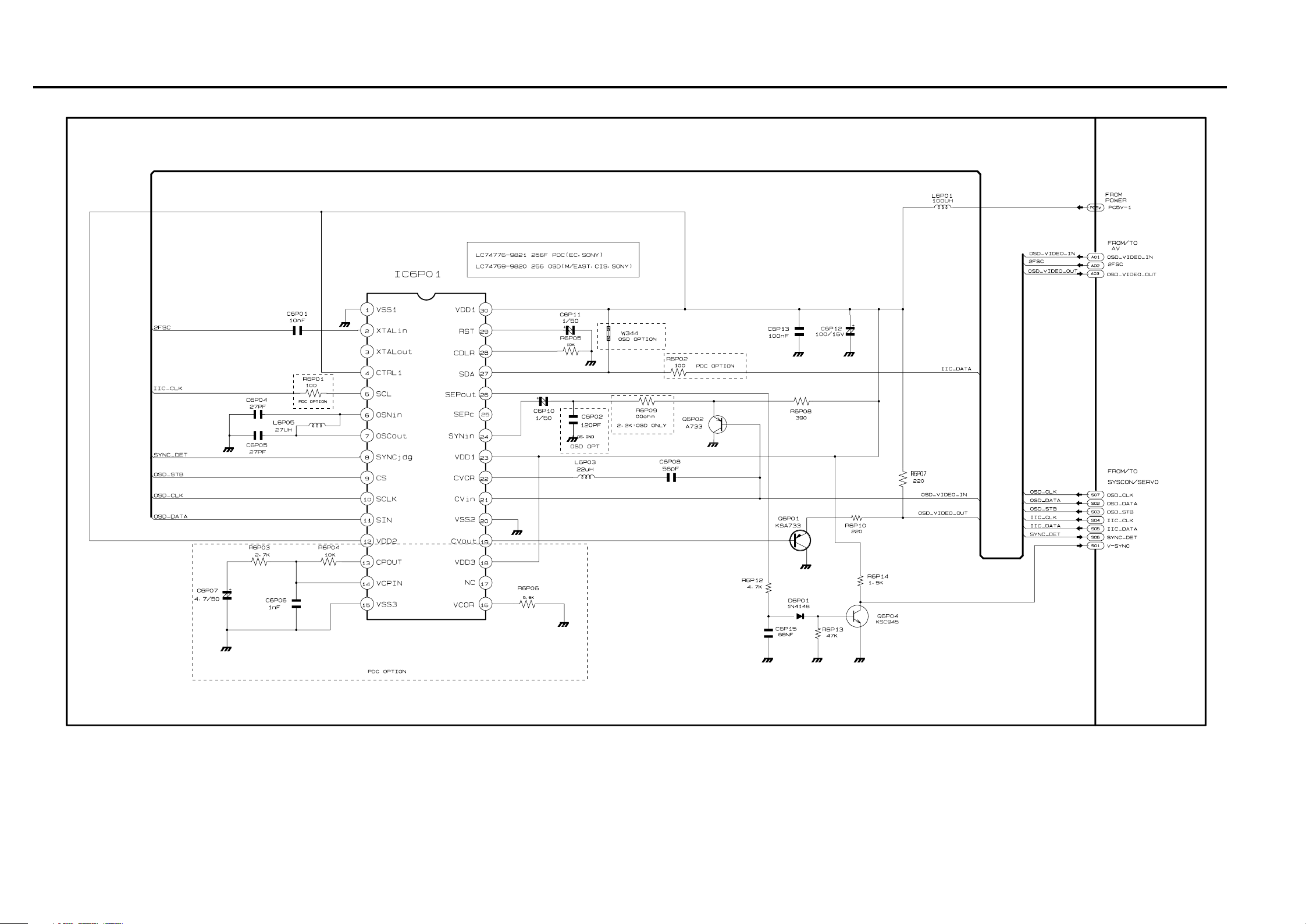
5-3 OSD/VPS/PDS
5-85-7
Page 6

5-4 A2/NICAM
5-105-9
Page 7

5-5 A/V
5-125-11
Page 8

5-6 Hi-Fi
5-145-13
Page 9

5-7 Input-Output (2 Scart Jack)
5-165-15
Page 10
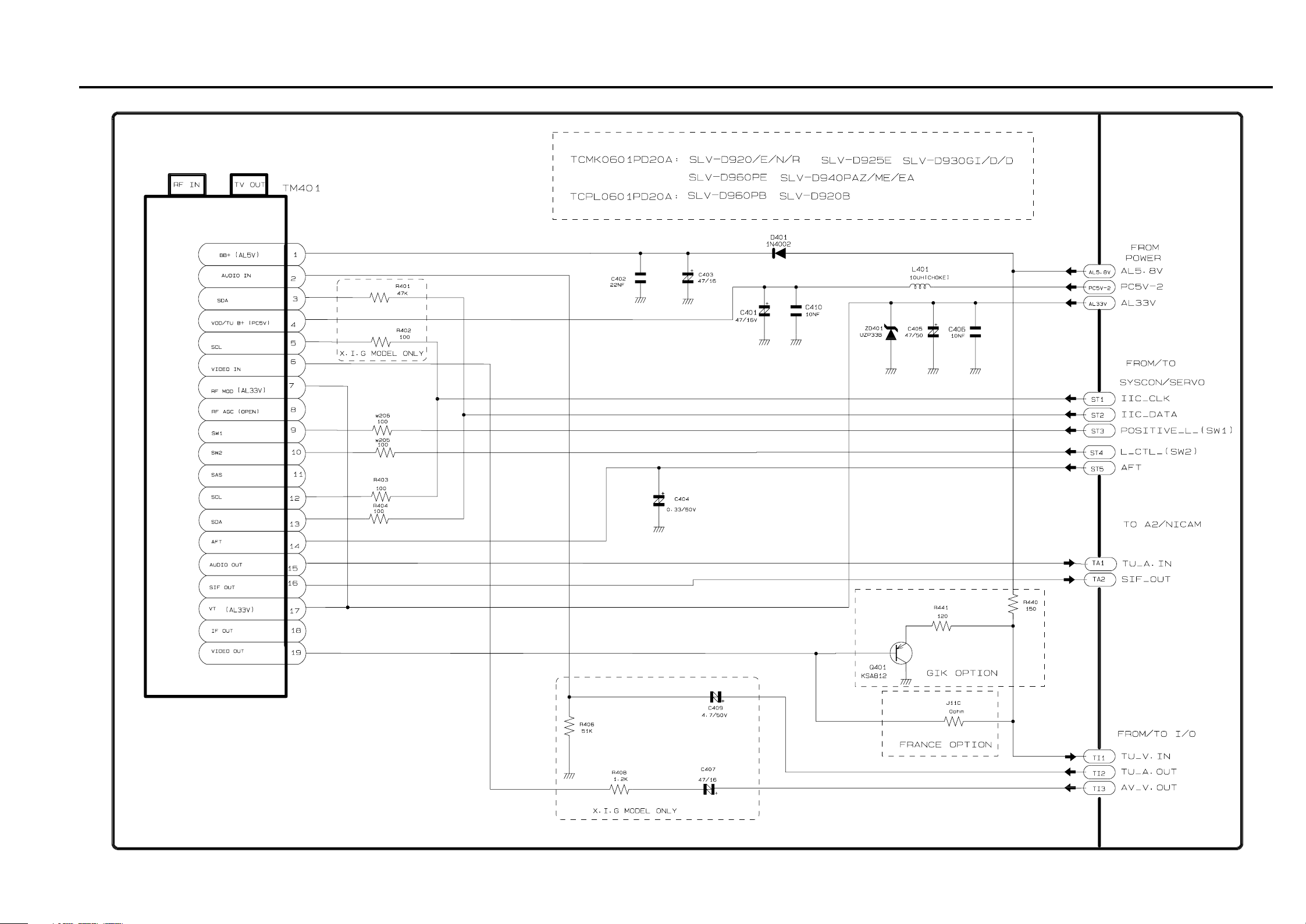
5-8 TM
5-185-17
Page 11
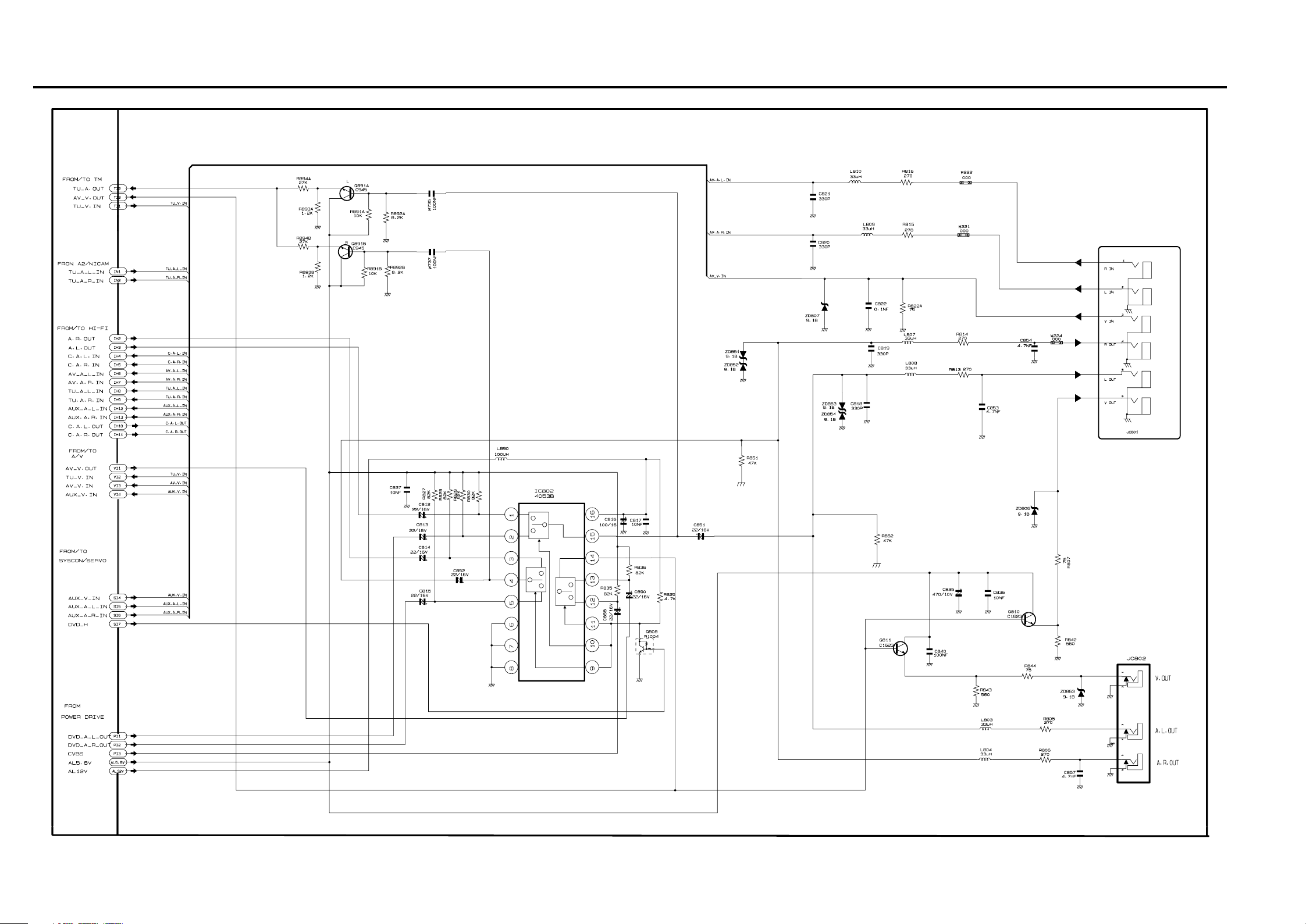
5-9 I/O (RCA)
5-205-19
Page 12
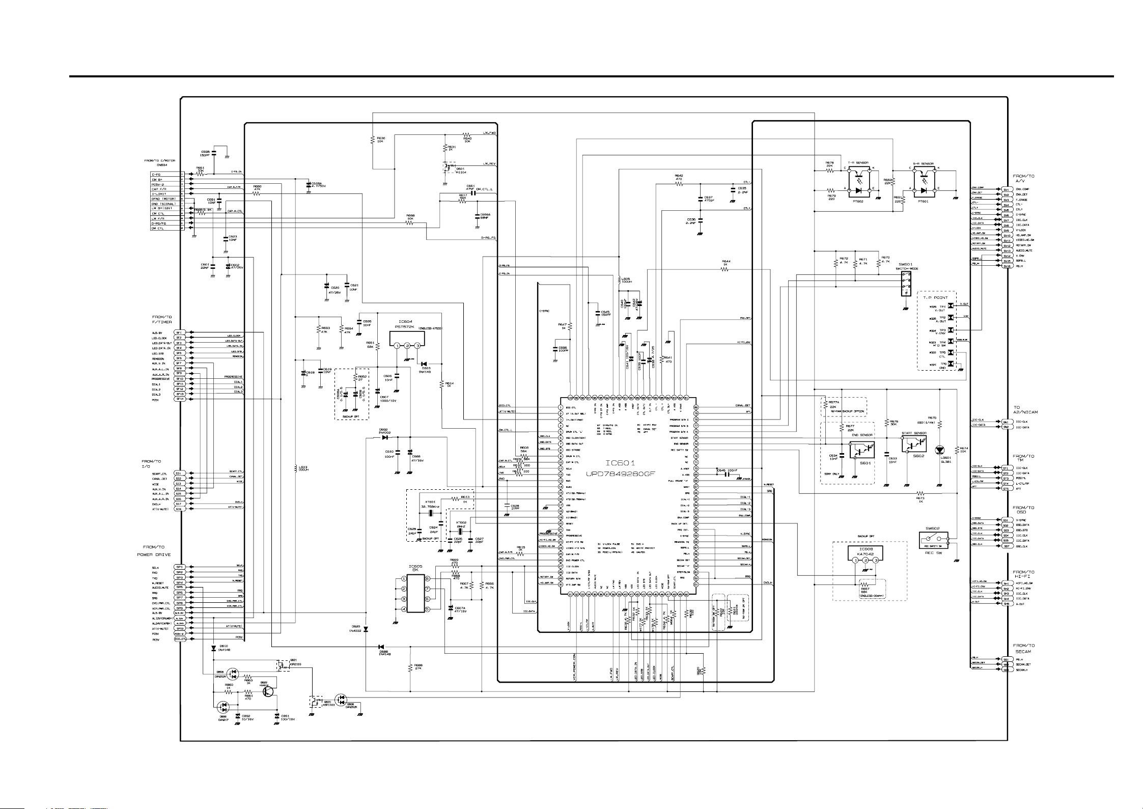
5-10 SYSCON
5-225-21
Page 13
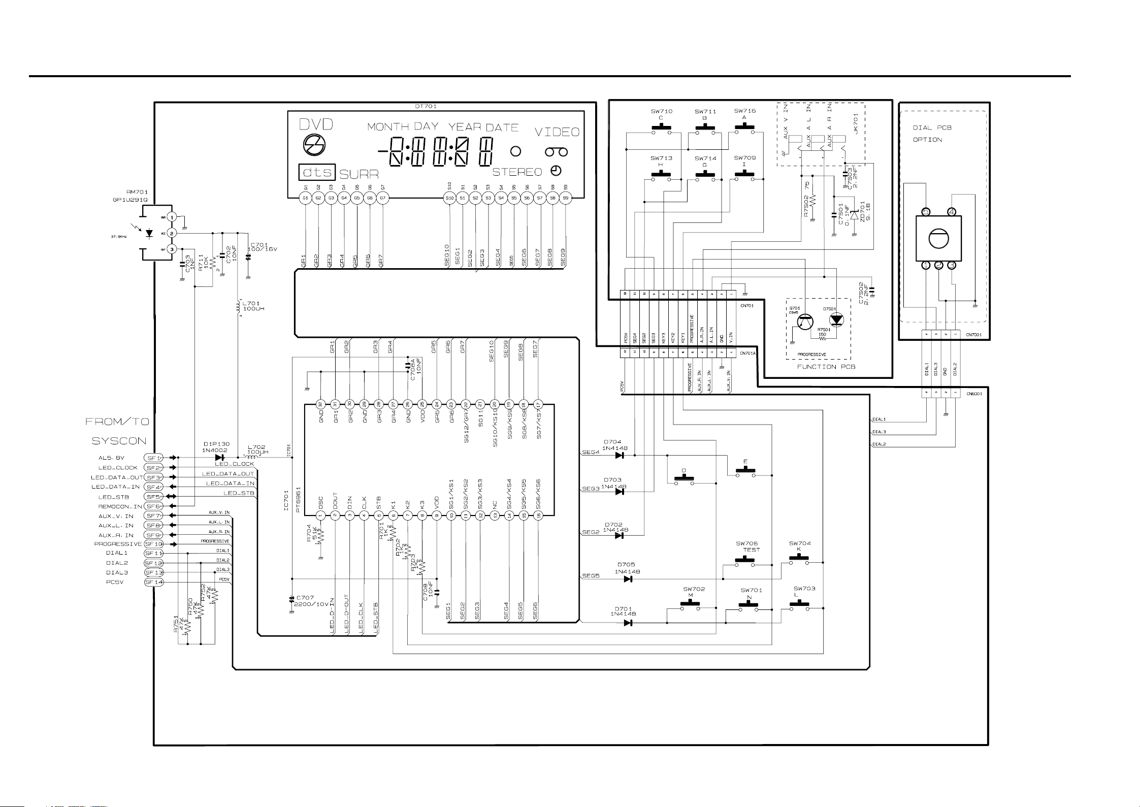
5-11 Logic/Function
5-245-23
Page 14
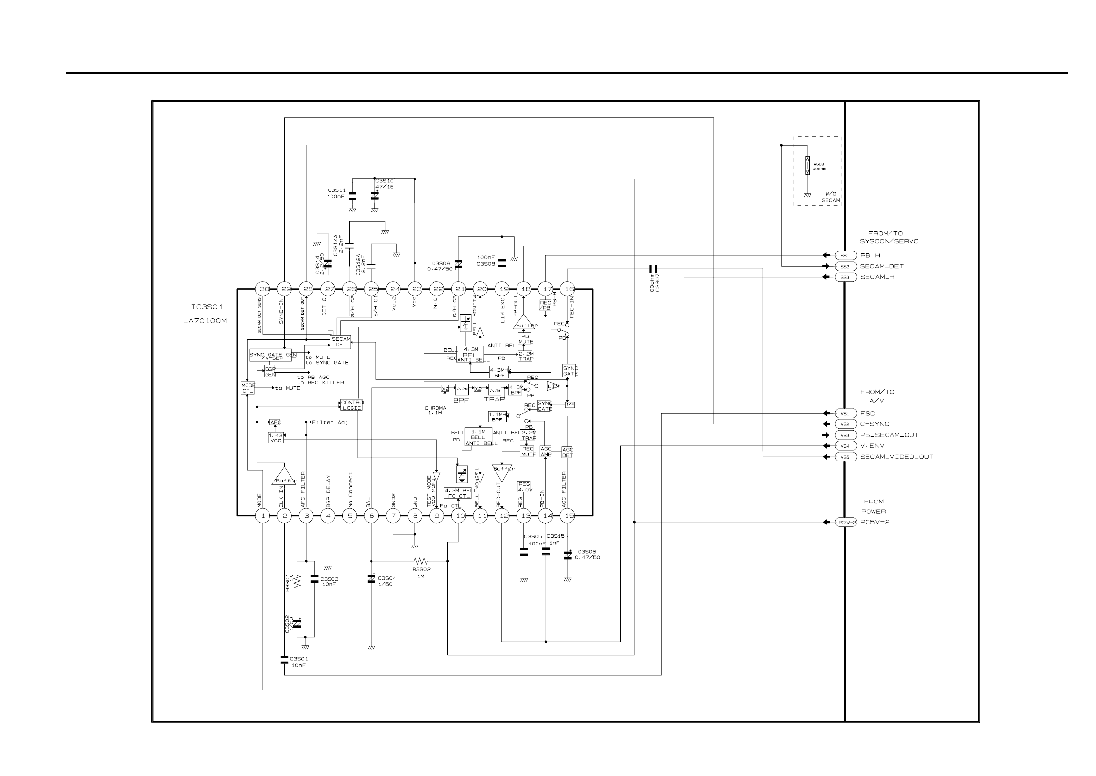
5-12 SECAM (SLV-D920 B/D960P B)
5-265-25
Page 15
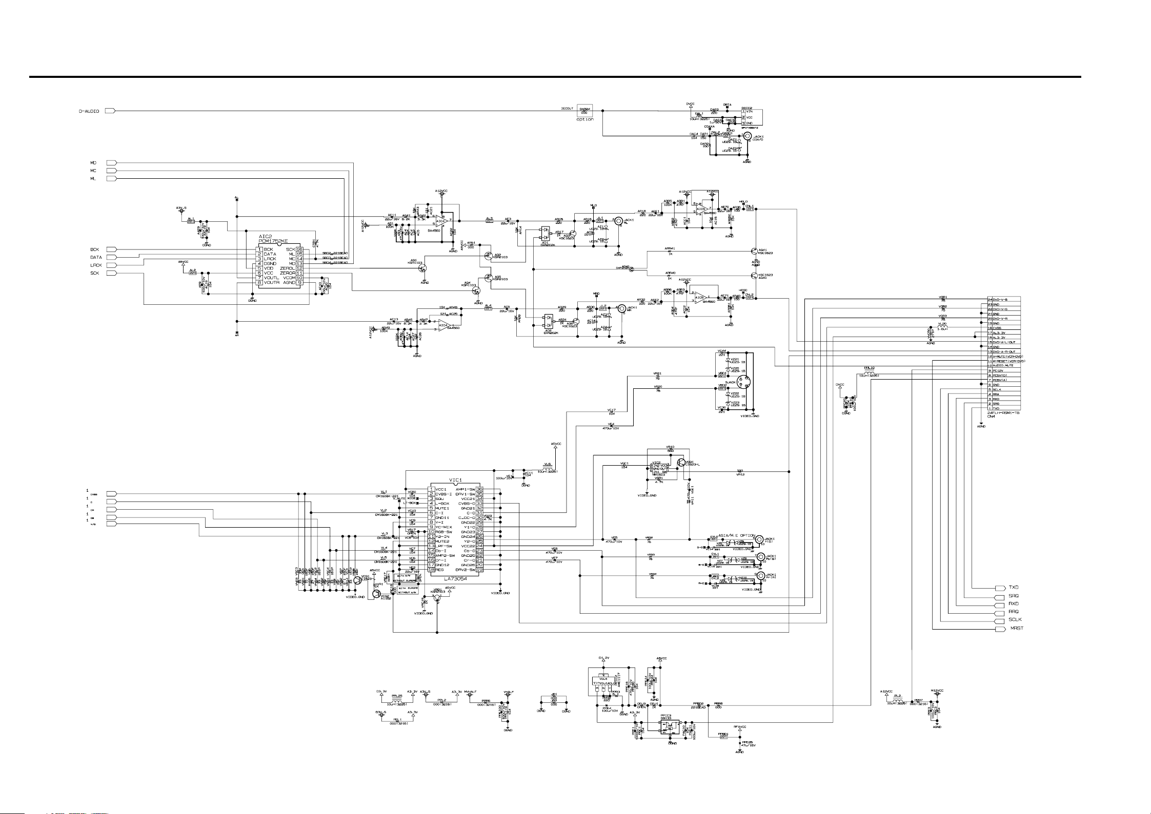
5-13 DVD A/V
5-285-27
Page 16
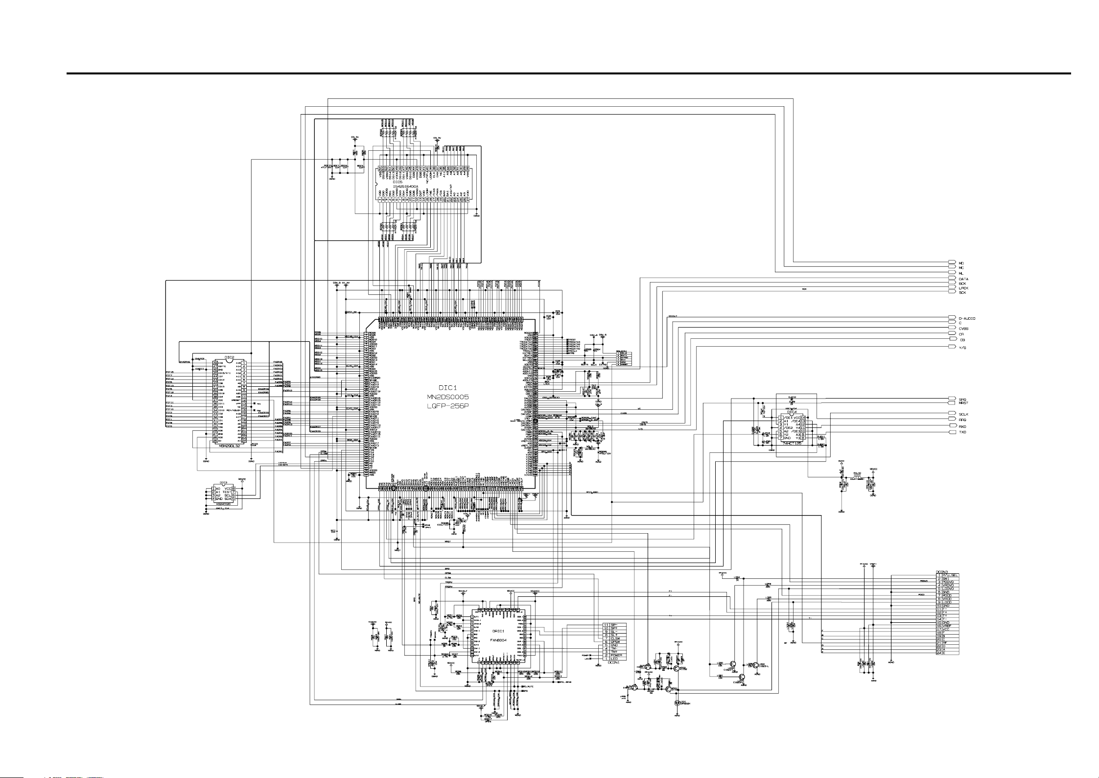
5-14 DVD Decoder Servo
5-305-29
Page 17
SLV-D920 B/D920 E/D920 N/D920 R/D925 E/
D930 D/D930 GI/D960P B/D960P E
6. ALIGNMENT AND ADJUSTMENTS
6-1 VCR ADJUSTMENT
6-1-1 Reference
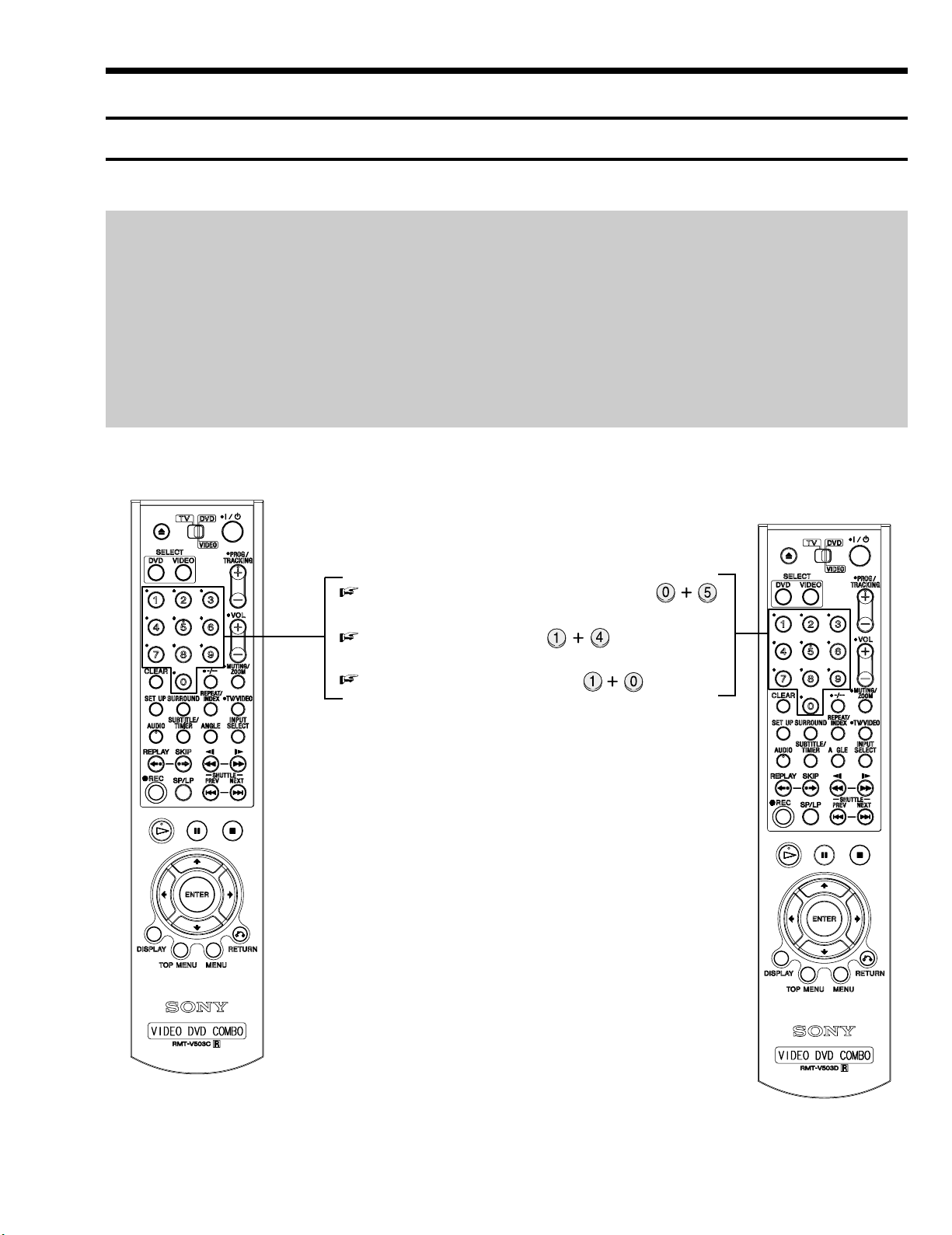
1) X-Point (Tracking center) adjustment, “Head switching adjustment” and “NVRAM option setting” can be adjusted with remote control.
2) When replacing the Main PCB Micom (IC601) and NVRAM (IC605: EEPROM) be sure to adjust the “Head switching adjustment” and
“NVRAM option setting”.
3) When replacing the cylinder ass’y, be sure to adjust the “X-Point” and “Head switching adjustment”.
4) How to adjustment.
- Intermittently short-circuit the Test Point on Main PCB with pincers to the adjustment mode.
- If the corresponding adjustment button is pressed, the adjustment is performed automatically.
- When the adjustment is completed, be sure to turn the power off.
6-1-1(a) Location of adjustment button of remote control
X-Point (Tracking Center) Adjustment ;
NVRAM Option Setting ;
Head Switching Adjustment ;
Fig. 6-1
6-1
Page 18
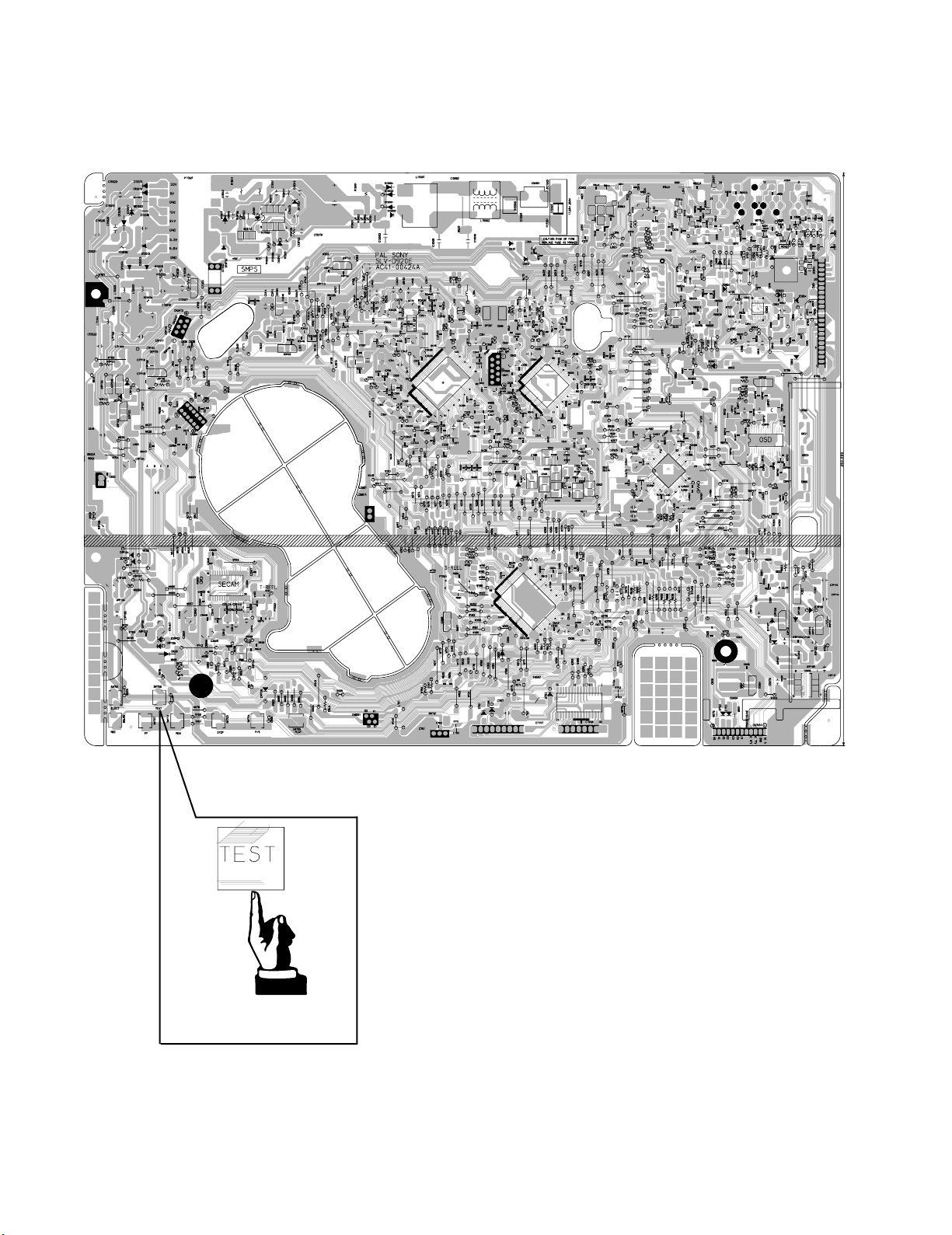
6-1-1(b) TEST location for adjustment mode setting
TEST
TEST BUTTON
Fig. 6-2 VCR Main PCB (Top View)
6-2
Page 19
6-1-2 Head Switching Point Adjustment
1) Playback the alignment tape.
2) Press the “TEST” botton on VCR MAIN PCB to set the adjustment mode. (See Fig. 6-2)
3) Press the “1, 0” buttons ; remote control adjustment operates automatically. (See Fig. 6-1)
6-1-3 NVRAM Option Setting
1) NVRAM Option is adjusted in the factory.
2) In case Main PCB Micom (IC601) and NVRAM (IC605 ; EEPROM) are replaced, be sure to set the corresponding option number of the
required model. (If the option is not set, the unit will operate.)
1) Press the “TEST” botton on VCR MAIN PCB to set the adjustment mode.
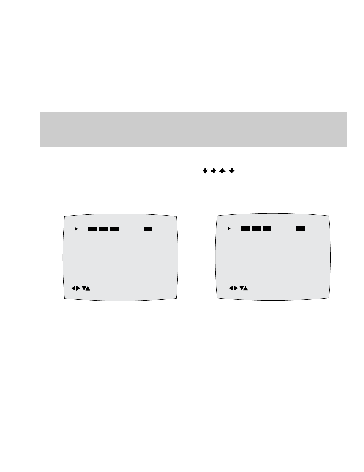
2) Press the “1, 4” buttons on the remote control. The option setting is appears. (See Fig. 6-3)
3) Select the option number (See table 6-1) of corresponding model with “
4) After selecting the option number is completed, press the “ENTER” button of remote control.
(If “ENTER” button is pressed, the selected number is changescolor. ; See Fig. 6-4)
5) Press the “RETURN” button of remote control again to store the option number.
6) Turn the Power off.
, , , ” buttons on the remote control.
01 02 03 04 05 06 07 08
09 10 11 12 13 14 15 16
17 18 19 20 21 22 23 24
25 26 27 28 29 30 31 32
33 34 35 36 37 38 39 40
41 42 43 44 45 46 47 48
49 50 51 52 53 54 55 56
57 58 59 60 61 62 63 64
65 66 67 68 69 70 71 72
CHG : OK SAVE : RETURN
Fig. 6-3 Fig. 6-4
01 02 03 04 05 06 07 08
09 10 11 12 13 14 15 16
17 18 19 20 21 22 23 24
25 26 27 28 29 30 31 32
33 34 35 36 37 38 39 40
41 42 43 44 45 46 47 48
49 50 51 52 53 54 55 56
57 58 59 60 61 62 63 64
65 66 67 68 69 70 71 72
CHG : OK SAVE : RETURN
6-3
Page 20

< Table 6-1 NVRAM Option Table >
MODELS OPTION NUMBER
SLV-D920 E1 4, 5, 6, 7, 8, 9, 10, 11, 12, 13, 15, 16, 32, 34, 35, 38, 40, 42, 45, 47, 50, 60, 61, 63, 68, 69, 70, 71, 72
SLV-D920 E2 4, 5, 6, 7, 8, 9, 10, 11, 12, 13, 15, 16, 32, 34, 35, 38, 40, 42, 45, 47, 50, 60, 61, 63, 68, 69, 70, 71, 72
SLV-D920 B 4, 5, 6, 7, 8, 9, 10, 11, 12, 13, 15, 16, 20, 21, 26, 32, 33, 34, 35, 36, 38, 40, 45, 47, 50, 60, 61, 63, 68, 69, 70, 71, 72
SLV-D925 E 4, 5, 6, 7, 8, 9, 10, 11, 12, 13, 15, 16, 32, 34, 35, 38, 40, 42, 45, 47, 50, 60, 61, 63, 68, 69, 70, 71, 72
SLV-D930 GI 3, 4, 5, 6, 8, 9, 10, 11, 12, 13, 15, 25, 26, 32, 33, 34, 35, 38, 40, 41, 45, 47, 50, 60, 61, 63, 68, 69, 70, 71
SLV-D930 D 2, 4, 5, 6, 7, 9, 10, 11, 12, 13, 15, 16, 32, 34, 35, 38, 40, 42, 45, 47, 50, 60, 61, 63, 68, 69, 70, 71, 72
SLV-D920 N 4, 5, 6, 7, 8, 9, 10, 11, 12, 13, 15, 16, 20, 32, 36, 38, 42, 45, 47, 50, 60, 61, 63, 68, 69, 70, 71, 72
SLV-D920 R 6, 7, 8, 9, 10, 11, 12, 13, 15, 20, 32, 36, 37, 39, 42, 43, 45, 47, 50, 54, 60, 61, 63, 68, 69, 70, 71
SLV-D960P E1 2, 4, 5, 6, 7, 8, 9, 10, 11, 12, 13, 15, 16, 32, 34, 35, 38, 40, 42, 45, 47, 48, 49, 60, 61, 63, 64, 67, 68, 69, 70, 71, 72
SLV-D960P E2 2, 4, 5, 6, 7, 8, 9, 10, 11, 12, 13, 15, 16, 32, 34, 35, 38, 40, 42, 45, 47, 48, 49, 60, 61, 63, 64, 67, 68, 69, 70, 71, 72
SLV-D960P B 2, 4, 5, 6, 7, 8, 9, 10, 11, 12, 13, 15, 16, 20, 21, 26, 32, 33, 34, 35, 36, 38, 40, 45, 47, 48, 49, 60, 61, 63, 64, 67, 68, 69, 70, 71, 72
6-4
Page 21
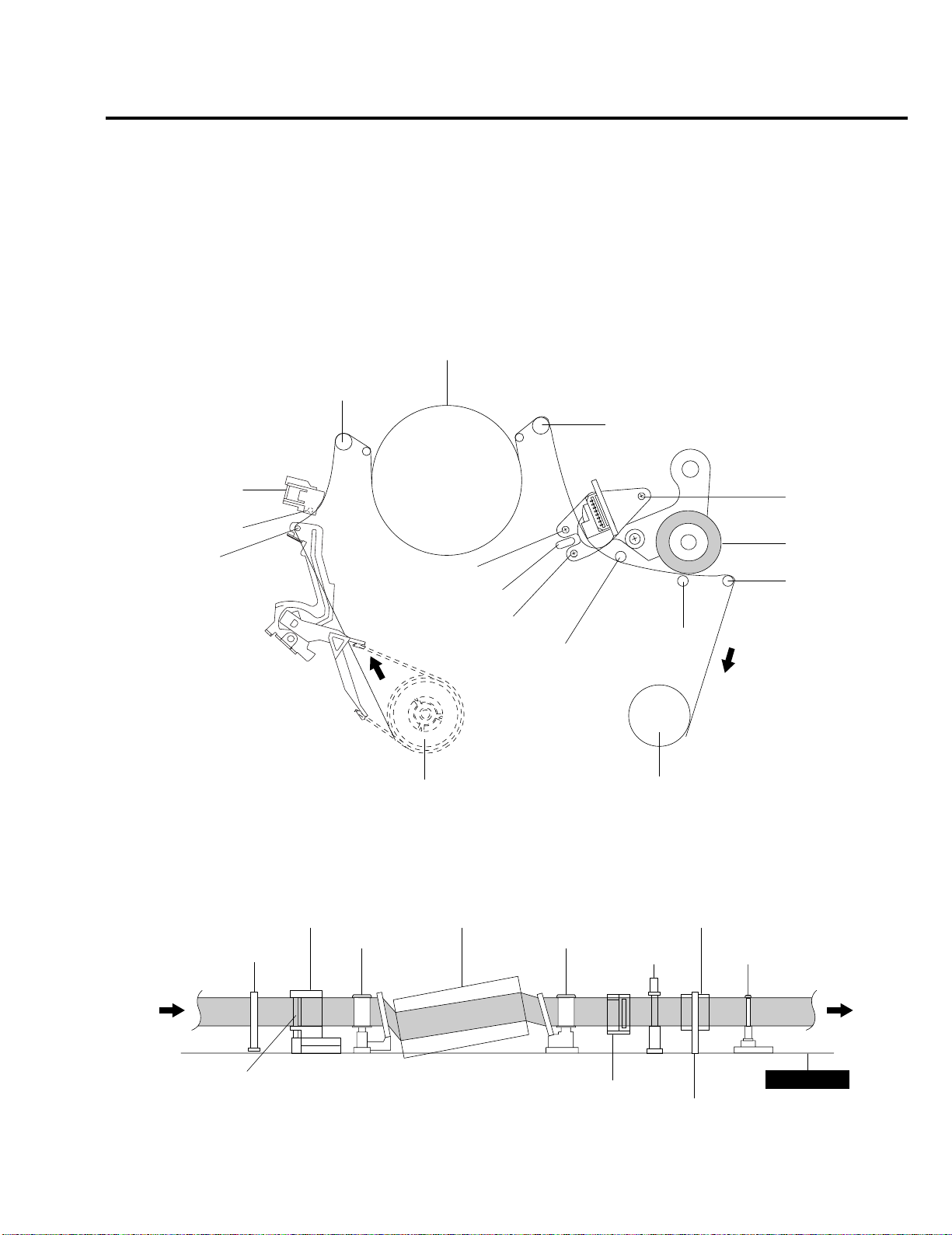
6-2 VCR MECHANICAL ADJUSTMENT
6-2-1 Tape Transport System and Adjustment Locations
The tape transport system has been adjusted precisely in the factory. Alignment is not necessary except for the
following :
1) Noise observed on the screen.
2) Tape damage.
3) Parts replacement in the tape transport system.
Lower flange height of tape guide is used as the reference for the transport adjustment.
To maintain the height of the tape guide and prevent damage, do not apply excessive force onto the main base.
CYLINDER ASS'Y
GUIDE ROLLER "S"
GUIDE ROLLER "T"
FULL ERASE HEAD
#3 GUIDE POST
TENSION POST
POST TENSION
TILT SCREW
X - POSITION
ADJUST SILT
AZIMUTH SCREW
#8 GUIDE POST
SUPPLY REEL DISK
Fig. 6-5 Location of Tape Transport Adjustment
FE HEAD CYLINDER ASS'Y
GUIDE ROLLER "S" GUIDE ROLLER "T"
HEIGHT SCREW
PINCH ROLLER
#9 GUIDE POST
CAPSTAN
TAKE UP REEL DISK
PINCH ROLLER
#8 GUIDE POST #9 GUIDE POST
#3 GUIDE POST
Fig. 6-6 Tape Travel Diagram
6-5
ACE HEAD
MAIN BASE
CAPSTAN SHAFT
Page 22
6-2-2 Tape Transport System Adjustment
When parts are replaced, perform the required adjustments by referring to procedures for the tape transport
system. If there are any changes to the tape path, first run a T-120 tape and make sure excessive tape wrinkle does not occur at the tape guides.
◆ If tape wrinkle is observed at the guide roller S, T, turn the guide roller S, T until wrinkle disappears.
◆ If the tape wrinkle is still observed at the tape guide, perform the tilt adjustment of the ACE head.
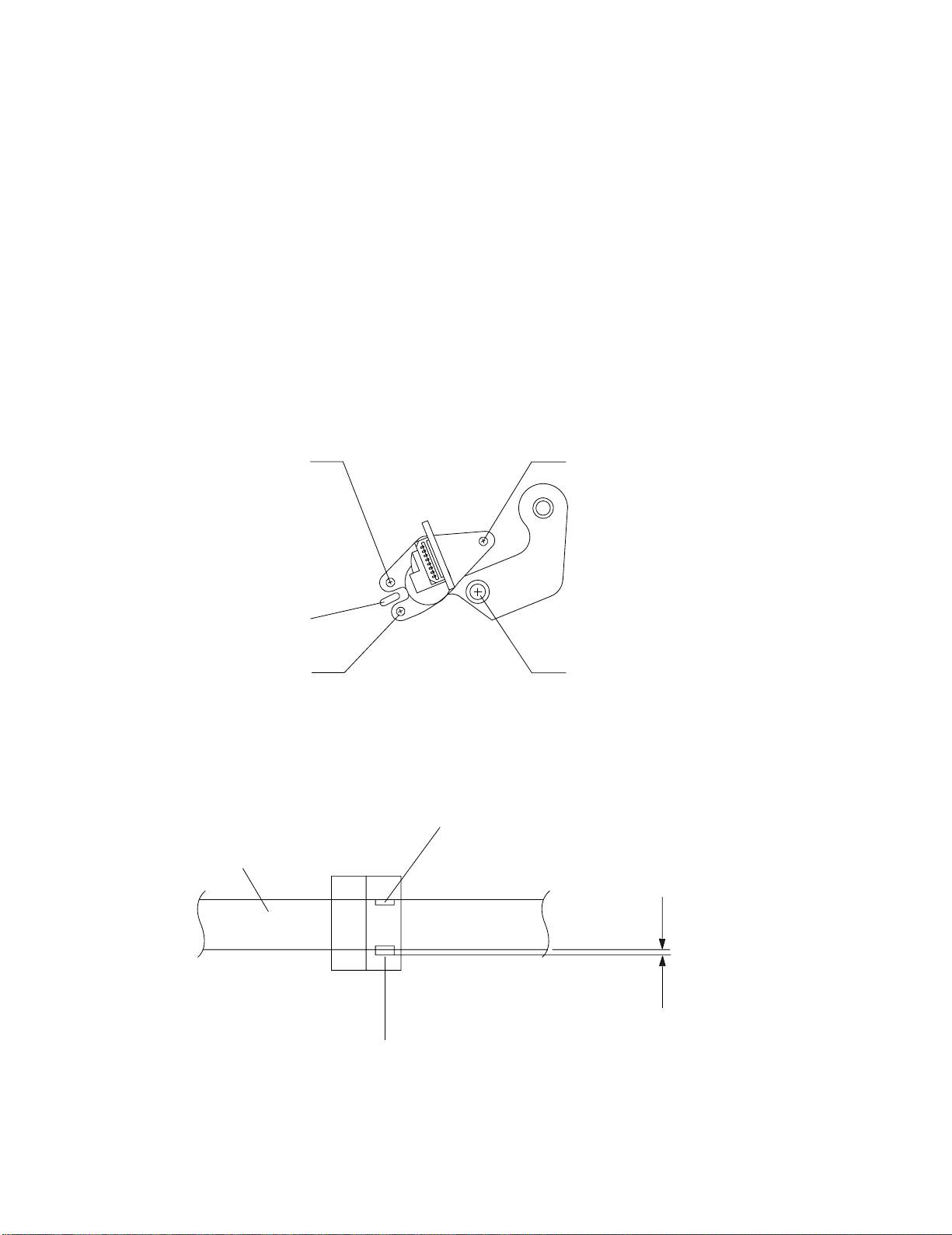
(1) ACE Head Assembly Adjustment
a. ACE HEAD HEIGHT ADJUSTMENT
1) Run the alignment tape (Color bar) in the playback mode.
2) Observe surface of the audio head using a dental mirror.
3) Turn screw (C) c lockwise or counterclockwise until the gap of lower tape edge and the lo wer edge of the control head is about 0.25mm. (Refer
to Fig. 6-7 and 6-8)
SCREW (A)
TLIT ADJUST
X-POSITION
ADJUSTING SLIT
SCREW (B)
AZIMUTH ADJUST
VIDEO HEAD
SCREW (C)
HEIGHT ADJUST
SCREW (D)
X-POSITION LOCKING
Fig. 6-7 Location of ACE Head Adjustment Screw
AUDIO HEAD
CONTROL HEAD
Fig. 6-8 ACE Head Height Adjustment
6-6
0 ~ 0 .25 mm
Page 23
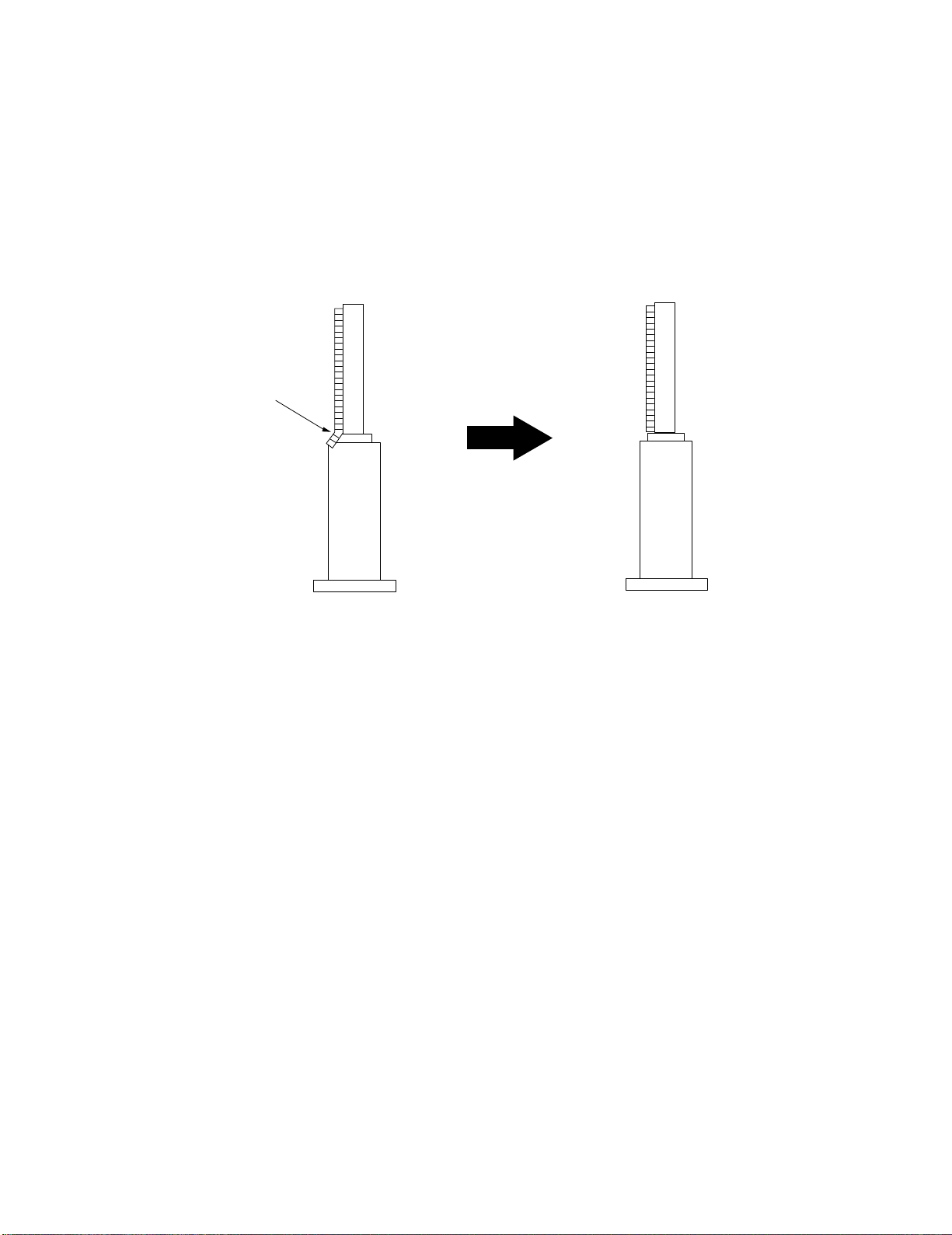
b. ACE HEAD TILT ADJUSTMENT
1) Playback a blank tape and observe the position of the tape at the lower flange of tape guide.
2) Confirm that there is no curl or wrinkle at the lower flange of tape guide as shown in Fig. 6-9 (B).
3) If a curl or wrinkle of the tape occurs, slightly turn the screw (A) tilt adjust on the ACE head ass’y.
4) Reconfirm the ACE head height.
(A) (B)
WRINKLE
(BAD)
Fig. 6-9 Tape Guide Check
c. AUDIO AZIMUTH ADJUSTMENT
1) Load alignment tape (Mono scope) and playback the 6KHz signal.
2) Connect channel-1 scope probe to audio output.
3) Adjust screw (B) to achieve maximum audio level. (See Fig. 6-7)
(GOOD)
6-7
Page 24
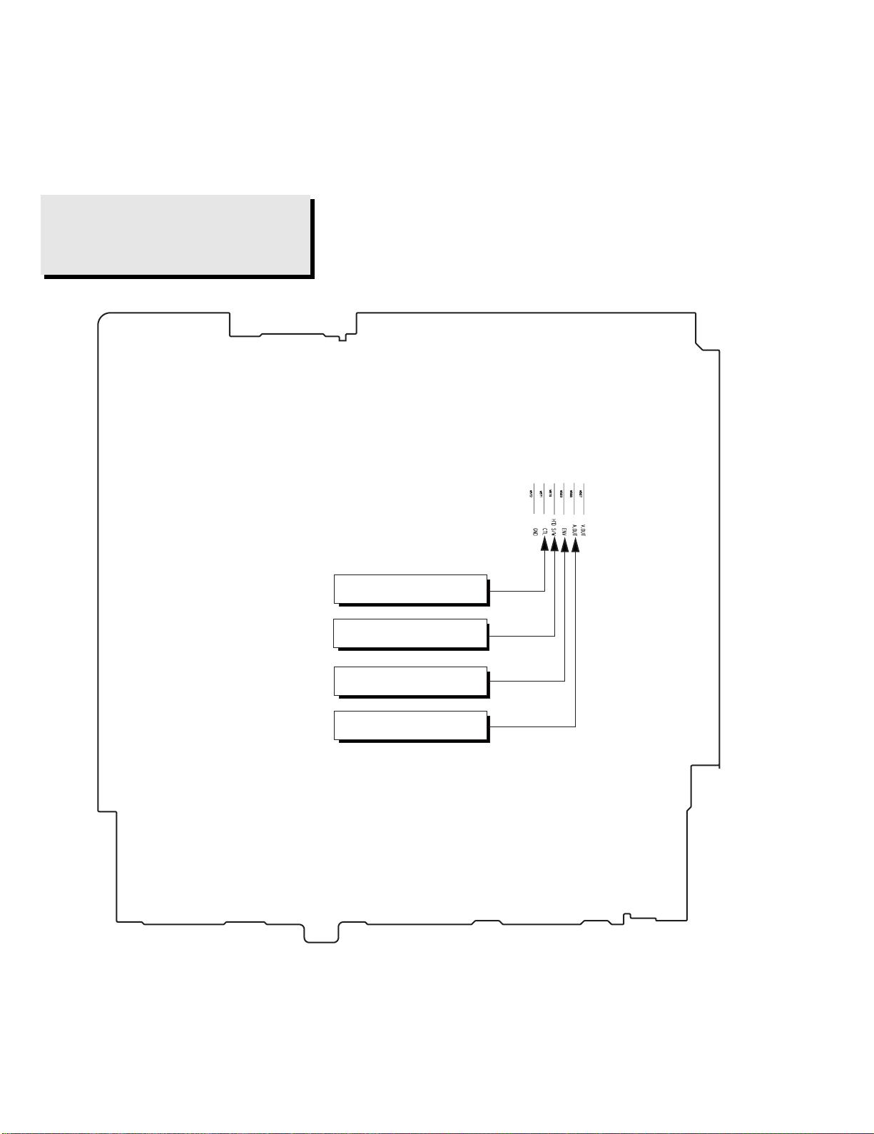
d. ACE HEAD POSITION (X-POINT) ADJUSTMENT
1) Playback the alignment tape (Color bar)
2) Press the “TEST” botton on VCR MAIN PCB to set the adjustment mode. (See Fig. 6-2)
3) Press the “0, 5” remote control buttons, then adjustment is operates automatically. (See Fig. 6-1)
4) Connect the CH-1 probe to “Envelope” the CH-2 probe to “H’D switching pulse” and then trigger to CH-1.
5) Insert the (-) driver into the X-Point adjustment hole and adjust it so that envelope waveform is maximum.
Test point: W568 (Audio Output)
W569 (Envelope)
W570 (H’D S/W -Trigger)
W571 (Control Pulse)
CONTROL PULSE
HEAD SWITCHING
ENVELOPE
AUDIO OUTPUT
Fig. 6-10 Location of Test point (VCR Main PCB-Top View)
6-8
Page 25
(2) Linearity adjustment (Guide roller S, T adjustment)
1) Playback the Mono Scope alignment tape (SP mode).
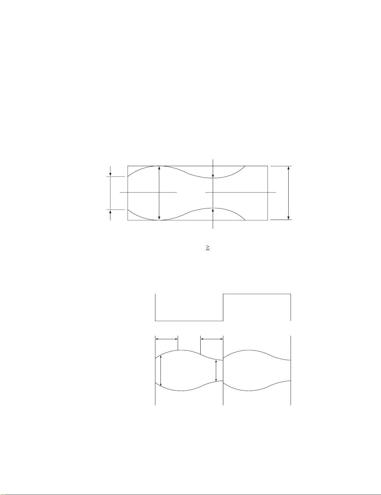
2) Observe the video envelope signal on an oscilloscope (triggered by the video switching pulse).
3) Make sure the video envelope waveform (at its minimum) meets the specification shown in Fig. 6-11.
If it does not, adjust as follows :
Note:
a=Maximum output of the video RF envelope.
b=Minimum output of the video RF envelope at the entrance side.
c=Minimum output of the video RF envelope at the center point.
d=Maximum output of the video RF envelope at the exit side.
4) If the section A in Fig. 6-12 does not meet the specification, adjust the guide roller S up or down.
5) If the section B in Fig. 6-12 does not meet the specification, adjust the guide roller T up or down.
b
H'D SWITCHING PULSE
a
a b c d
c,b,d/a
c
63%
Fig. 6-11 Envelope Waveform Adjustment
A B
d
ENVELOPE
AB
Fig. 6-12 Adjustment Points
6-9
Page 26
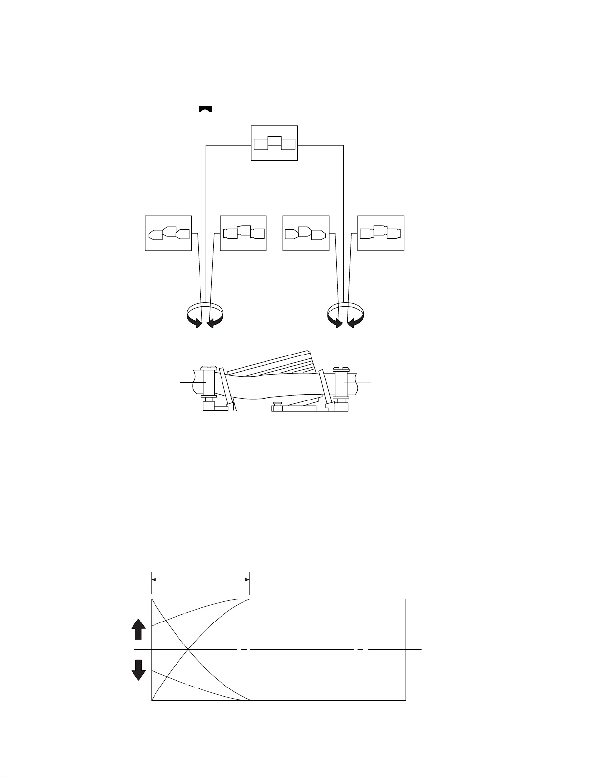
6) Play back the Mono Scope alignment tape (SP mode).
7) Connect an oscilloscope CH-1 to the “Envelope” and CH-2 to the “H’D SW Pulse” for triggering.
8) Turn the guide roller heads with a flat head (
) driver to obtain a flat video RF envelope as shown in Fig. 6-13.
IDEAL ENVELOPE
S HEIGHT TOO HIGH
GUIDE ROLLER S
S HEIGHT TOO LOW
T HEIGHT TOO HIGH
T HEIGHT TOO LOW
GUIDE ROLLER T
Fig. 6-13 Guide Roller S, T Height Adjustment
(3) Check Transitional Operation from RPS to Play
Check transition from RPS mode to play mode : Using a pre-recorded SP tape, make sure the entry side of envelope comes to an appropriate
steady state within 3 seconds (as shown in Fig. 6-14).
If the envelope waveform does not reach specified peak-to peak amplitude within 3 seconds, adjust as follows :
1) Make sure there is no gap between the supply roller lower flange and the tape.
If there is a gap, adjust the supply guide roller again.
2) Change operation mode from the RPS to the play mode (again) and make sure the entry side of envelope rises within 3 second.
ENTRANCE SIDE ENVELOPE
Fig. 6-14 Video Envelope Rising when Operation mode Changes from RPS to Play Mode
6-10
Page 27

(4) Envelope Check
1) Make recordings on T-120 (E-120) and T-160 (E-180) tape.
Make sure the playback output envelope meets the specification as shown in Fig. 6-15.
2) Play back a self recorded tape (recording made on the unit using with T-120 (E-120).
The video envelope should meet the specification as shown in Fig. 6-15.
In SP mode, (A) should equal (B).
If the head gap is wide, upper cylinder should be checked.
A
Fig. 6-15 Envelope Input and Output Level
(5) T ape Wrinkle Check
1) Run the T-160 (E-180) tape in the playback, FPS, RPS and Pause modes and observe tape wrinkle at each guide.
2) If excessive tape wrinkle is observed, perform the following adjustments in Playback mode :
◆ Tape wrinkle at the guide roller S, T section : Linearity adjustment.
◆ Tape wrinkle at tape guide flange : ACE head assembly coarse adjustment.
B
6-2-3 Reel Torque
1) The rotation of the capstan motor causes the holder clutch ass’y to rotate through the belt pulley.
2) The spring wrap PLAY/REV of holder clutch ass’y drives the disk reel S, T through gear idler by rotation of gear center ass’y.
3) Brake is operated by slider cam at FF/REW mode.
4) Transportation of accurate driving force is done by gears. (Gear Center Ass’y)
Note: If the spec. does not meet the followings specifications, replace the holder clutch ass’y and then recheck.
< Table 6-2 >
MODE TORQUE g/cm GAUGE
PB 42 ± 11 Cassette T orquemeter
RPS 145 ± 30 Cassette T orquemeter
6-11
 Loading...