

Page 1
ELECTRET CONDENSER STEREO
MICROPHONE
ECM-929LT
OPERATING INSTRUCTIONS page 2
Sony Corporation PriMed
in
Japan
2-599-188-12
(1)
Before using the microphone, please read
oughly. This manual should be retained for future reference.
this
manual thor-
MODE D'EMPLOI page 12
Avant la mise
mode d'emploi.
Conserver ce manuel pour
BEDIENUNGSANLEITUNG Seite
Vor Inbetriebnahme lesen Sie
aufmerksam durch.
Bewahren Sie diese Anleitung zum spateren Nachschlagen
gut auf.
©
1981
en
service du microphone, lire attentivement ce
by Sony Corporation
to
ute reference ulterieure.
bitte
diese Bedienungsanleitung
22
Page 2
English '
FEATURES
Mid·side capsules
A uni·directional capsule (for the mid microphone) and a bi·
directional capsule (for the side microphone) are installed ver.
tically
and close
The mid
side
The picked up sounds are then
nel
is a better stereo
truer
Compact and lightweight
Use
use, indoors
Back·electret condenser capsule
Back·electret system is used for the microphone capsules
obtain excellent
delity. '
Battery check lamp
LED indi
Stereo miniplug
This microphone is equipped
record in ste reo by connecting
stereo mini
microphone
~icrophone
electrically
duplication
this
microphone wi
cator
through
or
shows
jack
together
picks up
effect
of
outdoors.
transient
of
in
a single microphone body.
picks up sound from the front and the
the
sound from the left and right.
an
the original sound
th
the
a stereo cassette tape recorder.
split into a left and right chan·
M.S. matri x circuit. As a result there
with less " hole·in·the·middl
a stereo cassette·corder for portable
characteri
battery
cond ition.
with
a stereo
the
distribution.
stics
and improved fi·
miniplug
miniplug
. You can
directly
e"
to the
and a
to
Plug adaptor
The supplied plug adaptor is equipped
so that it can
jacks used
No
cross-talk
There can be no cross·talk between the right and left channels
because the
single cord.
Remote control
By
attaching
direc
tivity
TABLE
Precautions ..............................................
Battery
Installation
Battery life
Parts
Connections
More about
Remote
Microphone stand
Specifications .................. ,
be
used
in
many
two
channels use independent cable
the MRU-
characteristics c
OF
CONTENTS
.,
..............................
identifications
........
..........
microphone
control
with
phone
compact
..............
cassette recorders.
60
remote control unit (optional
an
be changed from a
..............
...
..................
...........
....
use ........
........
....
with
jacks
........
, ........
....
....
. , ..........
a uni-mafch plug
as well as
..................................... 4
.....................................
.....................
.................. ,
....................................... 9
....
with
...
......
, .......................
the mini
within
distan
....
....
),
the
ce.
........ 6
.....
,.
.. , ....
10
a
5
8
2
3
Page 3
PRECAUTIONS
On
microphone handling
• The
microphone
extreme shock.
• Keep
tures
• If the
ing
change the
stops, or
On
• The
tional
case
the
compartment.
• If the
the
• A mercury
phenomena). The powder will
ance,
wiping
•
circuit
•
OFF.
the
(above 60°C
microphone
effect
(acoustic
decrease the speaker volume.
battery
battery
battery
side is
the
battery
battery
Do
If
compartment, notice
microphone
.
but
it may result
the
battery
not
throw
the
poles as the
the
microphone
should
microphone
or
140°
is placed
feedback) may occur. If
direction
polarity
. Its
battery
of
is
button
plus
® pole. when you insert the
is
in
with a soft
the
discharged
is
not
away
F).
the
quite
side is
not
to
may become powdercoated (salting
poor
battery
to
never be dropped
from extremely high tempera,
too
near
microphone
different from
the
minus
an
illustration
be
used
for
not
affect
contact
. Remove
cloth
before use.
battery
may
explode.
be
used, set
or
subjected
the
speakers, a howl-
this
until
the
that
of
a conven-
e pole , and
battery
of
the
a long time, remove
the
battery
the
powder by
into
a fire , nor
the
mode
switch
to
happens,
howling
the
into
battery
perform-
short·
to
BATTERY
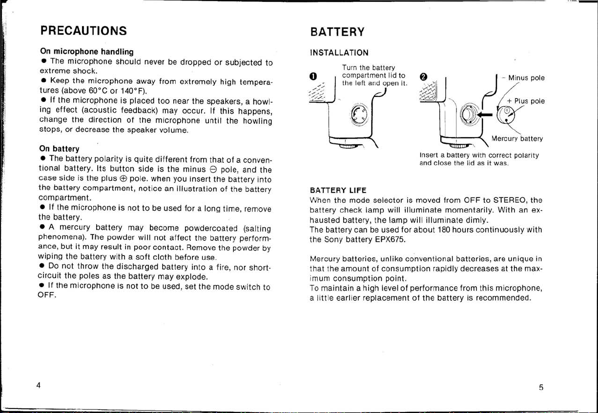
INSTALLATION
Turn the batt ery
co
mpartment lid to
left and open it.
the
Insert a battery with correct pola ri
and close the
BATTERY LIFE
When
the
mode
batt
ery check
hausted battery,
The
battery
t
he
Sony
Mercury batteries, unlike conventional batteries, are unique in
the
that
imum
To
a
amount
consumption
maintain a high
li
ttle
earlier replacement
selector
lamp
the
can be used
battery
EPX675.
of
is mo ved from OFF
will
illuminate
lamp
will
for
about
consumption
point.
level
of
performance from
of
the
illuminate
rapidly decreases at
lid
momentarily.
dimly.
180
hours
battery
is recommended.
as
it
was.
to
STEREO,
With
continuously
this
microphone
the
an
ty
the
ex·
with
max-
,
4
5
Page 4
PARTS IDENTIFICATION
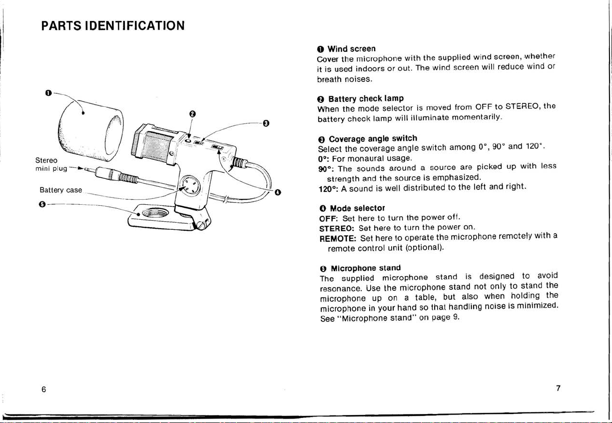
o Wind screen
Cover
the
microphone
it
is used
breath noises.
indoors
with
the
supplied wind screen,
or out. The wind screen
will
reduce wind
whether
or
0 - - -- - -
6
o Battery check
When
the
battery
check lamp
{)
Coverage angle
Select
the
0°:
For monaural usage.
900: The
strength
lamp
mode
selector
coverage angle
sounds
switch
around a source are picked up
and
the
o 120°: A sound is well
o Mode selector
OFF: Set here
STEREO: Set here
REMOTE: Set here
remote
()
Microphone stand
The supplied
resonance. Use
microphone
microphone
See
"Microphone
to
turn
to
control
unit
microphone
the
up on a table,
in
your
stand"
is moved
will
illuminate
switch
source is emphasized.
distributed
the
power
turn
the
to
operate
(optional).
microphone
hand so
on page
from
momentarily.
among 0·,
to
the
left
off
.
power on.
the
microphone
stand is designed
stand
not
but
also when
that
handling
9.
OFF
to
STEREO, the
90·
and 120
with
and right.
remotely
only
noise is minimized.
to
to
stand
holding
·.
less
with
avoid
the
the
a
7
Page 5
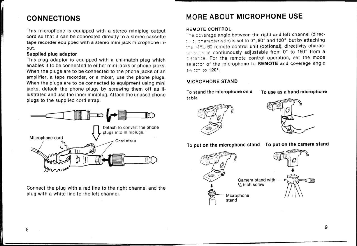
CONNECTIONS
MORE ABOUT MICROPHONE USE
This
microphone
cord so
tape
put
Supplied plug
This plug
enables it
When the
amplifier, a tape
When the plugs are
jacks, detach
lustrated
plugs
Connect
plug
that
recorder equipped
.
to
plugs are
and use
to
the
Microphone cord
the
with a white
is equipped
it
can
adaptor
adaptor
be
connected
recorder,
the
the
supplied cord
plug
with
line
with
be
connected
with
is equipped
to
to
be connected
or a mixer
to
be
connected
phone plugs by screwing
inner mini plug.
strap
a stereo
directly
a stereo mini
with
a uni·match plug
either mini
to
the
, use the phone plugs.
to
equipment
Attach
.
to
jack
jacks
phone
n Detach to convert the phone
V plugs into miniplugs.
Cord strap
a red line
to
the
left
to
the
right channel and
channel.
miniplug
a stereo
microphone
or
phone jacks.
jacks
using mini
them
the
off
unused phone
output
cassette
in-
which
of
an
as il-
the
REMOTE CONTROL
--~::';erage
. :
.. :-a'acteristic) is set
:
:-~ ',\
~U·6
::'-
~:,:s ~s
: s:=.-
s:'
~:::'r
::
,'.
::-
MICROPHONE STAND
To
stand the
lable
To
put
angle between
0
remote
contiunously
:~,
For the remote
of
the
microphone
:0120°,
microphone
on
the
microphone
control
the
right and
to
0°,90°
unit
(optional),
adjustable
control
to
REMOTE and coverage angle
on a
stand
To use as a
To
left
and 120°,
from
operation, set
put
but
directivity
0°
to
hand
on
the
channel (direc -
by
attaching
charac-
150° from a
the
mode
microphone
camera
stand
8
9
Page 6

SPECIFICATIONS
Type
OneSide
point
capsules
denser
condenser capsules)
Battery
Mercury battery, IEC deSignation MR44
(ANSI M15)
Dimensions
28 x 73
(1% x 27/8
Weight
Finish
Approx.
black
Mat
Supplied accessories
Microphone
Wind screen,
Carrying case,
Plug adaptor,
Stand screw
SAD
SAD
Sony
Power requirements Normal
Minimum
1.1
V
Current drain: Less
(at normal
Battery
Sony
Maximum
sound pressure
input
More
(at 1,000 Hz, 1 %
o
dB
= 2x 10-
stereo (employing the Mid -
technique), electret con-
microphone
x 106 (w/h/d)
1
x 4
/
4
80
g(2.8
(with back-electret
inches)
oz)
finish
stand
, (
1)
(1)
(1)
(1)
35
(1)
35
(1)
mercury
operating
operating
adaptor
for
for
SAD
European model
USA model
battery
EPX675,
voltage: 1.35 V
voltage: Approx.
than 1 mA
operating
life
: Approx . 180 hours
battery
voltage)
EPX675
level
than
120 d B SPL
distortion,
4
1'
bar)
34
(1),
(1)
with
Erv!ronmental
Desi gn and
specifications
temperatures
-20
°C
storage
O°C
to
operation
to
60°C
60°C
subject
(32
to
(-4
°F
°F
to
change
to
140°F)
140°
without
F)
for
for
notice
.
10
11
Page 7

CARACTERISTIQUES
Capsules centrales et laterales
Une
capsule
capsule
une
installes
corps
Le
microphone
microphones
Les
sons
canal gauche et droit, a travers
resulte un
duplication
une
Compact et legere
Utiliser
tion
portative, a
unidirectionnelle
bidirectionnelle
verticalement et inseres ensemble dans
de microphone.
central capte
lateraux,
captes
sont
meilleur
ce
microphone
eftet
plus
fidele de
I'interieur
(pour
Ie
son venant de
ensuite
separes
stereo avec
avec
un
ou
en
(pour
Ie
microphone
Ie
microphone
Ie
son venant de I'avant et les
un
la
distribution
magnetophone
plein air.
droite
electriquement
circuit a matrice
moins
de "trou central" et
central) et
lateral)
un
et de gauche.
dans
M.S ..
du son
originel.
pour I'utilisa-
sont
seul
un
II
en
Aclaptateur
L:ada;Jl
n at perme
Que de prises
f"""lagnetophones
Pas
I j 'l.y a pas de
lesdeux
Talecommande
En
rattachant
car
acteristiques
:lrstance.
de
fiche
ateur
de fiche fourni est equipe
ttant
aussi bien I'
de diaphonie
diaphonie
canaux
mini·format
compacts.
entre les
sont
independants en
la
telecommande
de
directivite
utilisation
largement
peuvent etre chan gees it
TABLE DES MATIERES
d'une
fiche
de prises
utilisees
canaux
droit
un
seul cordon.
MRU-60 (sur option), les
double
telephoniques
avec les
et gauche
for·
car
Capsule
Un
microphone
tranSit et une
Voyant
Un
Fiche
Ce
possible
directement
format
12
it
condensateur
systeme
de
verification de I'etat
indicateur
stereo mini·format
microphone
d'effectuer
d'une
d'electret
pour
obtenir
amelioration
a LED
indique
est
equipe
un enregistrement stereo en
cette
fiche
platine
magnetophone
it
electret arriere
arriere est
d'excellentes
de la fidelite.
de
I'etat
d'une
mini-format
utilise
pour
les
capsules
caracteristiques
la pile
de
la
pile.
fiche
stereo
mini-format.
branchant
sur une prise stereo mini-
a cassette.
Pnkautions
de
de
II
est
Utilisation
lde'1tification
COnnexions .
I~formations
Specifications
.....................
sur
Installation
Duree de la pile
microphone ...
Telecommande
Support
pile ..................................................................
des elements .........
...........
supplementaires
microphone
....................................
.............................................................. 14
....................................................................
......
...........................
............................................... 16
sur
I'utilisation
.....
.......
du
...
.............................
...........................
...
....
.....
..
15
...
18
..
19
20
13
Page 8

PRECAUTIONS
UTILISATION SUR PILE
Manipulation
• Ne
des
chocs
•
Ne pas exposer Ie
cessives
•
Si
Ie
du
jamais
laisser
violents
depassant
microphone
microphone
tomber
.
microphone
60°C (140°F).
se trouve
Ie
microphone
trop
pres des haut-parleurs, il
a des
ou lui faire
temperatures
subir
ex-
peut se produi"re un phenomene de hurlement (retroaction
acoustique).
Dans ce cas, changer
Ie
que
phenomene
disparaisse
direction
du
microphone
, ou reduire
jusqu'a
Ie
volume des haut-
ce
la
parleurs.
Sur
pile
• La polarite de la pile est tres
ment
utilisees.
cote
boitier
Ie
logement , regarder une
Si
Ie
•
periode
Une pile au mercure peut se couvrir de poudre (phenomene
•
de
formation
ment
de la pile
tact
. Retirer les
• Ne
jamais
ne
jamais
Le
cote
touche
est Ie pole
microphone
positif
n'est
prolongee, retirer la pile.
de sel).
jeter
Celie
mais
peut etre a I'
depots
a I'aide
une pile dEkhargee de ce
court-circuiter
differente
est Ie pole ne
. Quand on
illustration
des piles
introduit
gatif
habituelle
tandis
la
pile dans
du logement pile.
que Ie
pas appele a servir pendant une
poudre
d'un
n'affecte
origine
d'une perte de con-
chiffon
doux avant usage.
type
en
rien
dans
Ie
Ie
rende-
feu ou
ses deux poles. Ceci peut la faire ex-
ploser.
•
Si
Ie
mode
microphone
sur OFF .
n'est pas
utilise, placer
I'interrupteur
de
INSTALLATION
Faire tourner Ie couvercle
du
logement pile dans Ie sens
ontraire
c
montre et
-
DUREE DE
Quand
OFF sur STEREO,
brille
des aiguilles d'une
Ie
retire
r.
LA
Ie
PILE
selecteur
de mode de
Ie
voyant de ver
momentanement.
In
serer une pile avec la polarite
correcte et remettre
plac
e.
en
fonctionnement
ification
de
Avec une pile usee,
Ie
couvercle
est place de
!'etat
de la pile
Ie
voyanl
brille
faiblement.
Le
fonctionnement
sur pile peut etre
effectue
pendant environ
180 heures avec la Pile Sony EPX675.
Les piles au mercure ,
nelles, sont
puissance
niveau de
Pour
maintenir
ecceptionnelles
diminue
consommation maximum.
un rendement
contrairement
par
aux piles convention-
Ie
fait
que leur niveau de
rapidement lorsqu 'elles
optimal
de ce
microphone
atteignent
, il est
un
preferable de rem placer la pile un peu avant son epuisement
total.
14
15
Page 9

IDENTIFICATION
Logement pile
DES
ELEMENTS
o
o Ecran anti-vent
Lorsque
terieur, Ie recouvrir avec I'ecran anti-vent fourni.
L'ecran
()
Lorsque
OFF
brille
f)
Choisir
0°: Pour
90°: Les sons
120°:
Ie
microphone
anti·vent reduit les
Voyant de
sur
momentanement.
Selecteur
moins
Le
verification
Ie
selecteur de mode de
STEREO,
d'angle
un
des angles de recouvrement 0°, 90° et 120°.
Ie
son monophonique.
autours
grande, et la source est accentuee.
son sera
est
utilise
bruits
de
I'etat
Ie
voyant de verification de I'etat de la pile
de recouvrement
de la source
distribue
de
soit a I'interieur,
du vent et de la respiration.
de la pile
fonctionnement
sont
captes
droite
a gauche.
soit
est place de
sur
une largeur
a I'ex-
16
o Selecteur de mode de
OFF:
Le
placer
sur
STEREO:
REMOTE:
{)
Le
nances.
phone uniquement pour
squ'il est tenu a la main de
manipulation.
Voir
Le
sous
microphone a I'aide de la telecommande
Support
support
"Support
placer sur cette position pour mettre I'appareil
tension.
Le
placer sur
microphone
microphone fourni est
II
est preferable de ne pas
microphone",
fonctionnement
cette
position
cette
Ie
pour couper
position pour telecommander Ie
conc;:u
utiliser
placer sur une table, mais aussi lor·
fac;:on a diminuer
a la page
I'alimentation.
(en
option).
pour eviter les reson·
Ie
support
19.
les
micro·
bruits
de
17
Page 10

CONNEXIONS
Ce
microphone
format
afin
a
cassette
format.
Adaptateur de fiche fourni
Cet
adaptateur
qui permet
sur
les prises
connectees
magnetophone
ques. Lorsque les
mini-format,
dlque
sur
mini-format
lisees
sur
Cordon du
est
de pouvoir
equipe
Ie
aux
I'illustration.
interieure.
Ie
microphone
equipe
Ie
d'un entree de
de
fiche
branchement
telephoniques.
prises
telephoniques
ou un melangeur,
fiches
enlever les fiches
Attacher
collier
de
transport
est
en
d'un
brancher
dOlvent etre
cordon a fiche
a un
equipe
d'une
tant
sur les prises
Lorsque les
utiliser
telephonlques
les devissant. et
les
fiches
fourni.
Detacher pour convertir les
fiches
fiches
{}
magnetophone
prise
microphone
fiche
double
mini-format
fiches
d'un
amplificateur,
les
fiches
connectees
comme
utiliser
telephonlques
telephoniques
mini·format.
collier
de
transport
stereo mini-
stereo
mini-
format
que
doivent
etre
d'un
telephoni-
a des prises
il est in-
la
fiche
inuti-
en
INFORMATIONS SUPPLEMENTAIRES
SUR L'UTILISATION
TELECOMMANDE
L'angle
(caracteristique
mais
possible
continue
Pour
teurde
ment
SUPPORT
Pour placer Ie microphone
sur une table
Pour mettre sur Ie support
microphone
de recouvrement
en
rattachant
Ie
fonctionnement
mode
sur
de
de regler les
de 0° a 150° a
sur
REMOTE et
0
120
.
MICROPHONE
directivite)
la
telecommande
caracteristiques
DU
entre
est place
distance.
de la
telecommande,
Ie
selecteur
MICROPHONE
les
canaux
MRU-60 (sur option), il
Pour
microphone tenu
Pour
de camera
droit
sur
0°, 90° et 120°,
de
directivite
placer
d'angle
I'utiliser comme
installer sur Ie trepied
de recouvre-
et
gauche
de fagon
Ie
it
la main
est
selec-
un
Connecter
droite
et la prise
gauche.
18
la
fiche
marquee
marquee
d'un
d'un
trait
trait
rouge
blanc
sur
sur
Ie
canal de
Ie
canal de
~~'
/ Trepied de camera
..
~suPPort
vis de '/. pouce
microphone
avec-~'
..
19
Page 11

SPECIFICATIONS
Type Type stereo integre (employ ant la
Pile Pile au mercure, MR44 selon
Dimensions
Poids Env.
Finition
Accessoires
Alimentation
fournis
technique
laterales),
electret (avec Ie
arriere)
designation
28x
(1%x27/ax4%
Noir
Support
Ecran anti-vent
Etui de
Adaptateur
Adaptateur
SAD
europeen
SAD
aux Etats-Unis
Pile au mercure Sony EPX675
Tension normale de
1,35V
Tension
Env.
Consommation
1
fonctionnement)
Duree de
la
des
capsules
microphone a condensateur
capsule
IEC (ANSI M15)
73x
106 mm
80
g (2,8onces)
mat
microphone
transport
34
35
minimum
1,1
mA
(a
Pile Sony EPX675
(1/h/p)
pouces)
(1)
(1)
(1)
de
fiche
(1)
de vis de
(1),
SAD
(1)
pour
V
la
tension
la
pile: Env. 180 heures avec
support
35
(1)
Ie
modele
fonctionnement:
de
fonctionnement
de
courant:
normale de
cent rales et
a electret
pour
la
Ie
destine
(1)
Moins
modele
:
de
Niveau d'entree a pression son ore
Temperature
La
conception
sans preavis.
Plus de
(a 1 000 Hz, 1 % de
o
-20
O°C a
et les
caracteristiques
120dB
dB
= 2x 10-
°C a +60°C
pour
stockage
+60
pour
fonctionnement
°C
maximum
SPL
4
1'
bar)
(-4°F
(+32°F
peuvent etre
distorsion
a +140°
a +140°F)
,
F)
modifiees
20
21
Page 12

Deutsch
BESONDERE MERKMALE
Axial-Iaterales Wandlersystem
Eine
Aufnahmekapsel
fonkapsel ) und eine aus zwei Richtungen aufnehmende Kapsel
(Seitenmikrofonkapsel)
zusammen in einem
krofonkapsel
krofon kapsel
aufgenommene
einen M.S.
Kanal verteilt . Das Ergebnis
ohne ein " Loch in der
Reproduktion des Original-Tons.
Kompakt und leieht
Gebrauch dieses
Cassettenrecorder eriTloglicht Tragbarkeit und
Einsatz
Gegenelektret-Kondensator-Aufnahmekapseln
Das Gegenelektret-System
ausgezeichnetes Einschwingverhalten und hervorragende
Klangwiedergabe.
Batteriekontrollampe
Der
Batteriezustand
Stereo-Ministeeker
Dieses
Wird der
Stereo-Cassettenrecorders
nom men werden.
nimmt
nimmt
Matrixschaltkreis
sowohl
Mikrofon
Ministecker
mit
axialer
Richtwir
sind vertikal Obereinander und eng
Mikrofonkorper
den Schall von vorne, und die Seitenmiden Schall von rechts und links auf. Die
Toninformation
Mille
Mikrofons
in geschlossenen Raumen als auch im Freien.
wird
durch
ist
mit
einem Stereo-Mi
direkt
wird dann elektrisch
auf
den linken und den rechten
ist
ein verbesserter
" und
zusammen
der
Mikrofonkapseln
einen LED-Indi
in die Stereo-
gesteckt
installiert.
somit
eine
nistecker
, kann
kung
(Mittenmikro-
Die
Stereoeffekt
naturgetreuere
mit
einem Stereo-
hochmobilen
kator
angezeigt.
Minibuchse
in
Stereo aufge-
Millenmi-
durch
sorgt
fOr
versehen.
eines
Zwisehensteeker
Bei dem
ein en
auch
Kein Oberspreehen
Obersprechen zwischen rechtem und linkem Kanal
ausgeschlossen,
voneinander
Fernbedienung
Wenn die Fernbedieneinhe
brac
werden.
mitgelieferten
Kombinationsstecker
in
eine Mi
nibuch
da
die beiden Kanale
Obertragen werden .
ht
wird, kann die Ri
Zwischenstecker
, der
se
gesteckt
sowohl
werden kann.
it
MRU-60
chtcharakteristik
handelt
in eine Klinken-als
in
einem Kabel getrennt
(Sonderzubehor) ange-
es sich um
ferngesteuert
INHALTSVERZEICHNIS
Zur besonderen Beachtung ...........................................
Batterie .................................
Einlegen
Ballerielebensdauer
Bezeichnung der Teile
AnschluB ....
Noch einige Tips zum Gebrauch des
Tec
hnische
............
Fernbedienung
rofonstander
Mik
Daten .......
....................................
...
...................................................... 25
....
.....................
........
......................................................... 30
...
....
.................................
...............
Mikrofons
....
......
...
...
..............
.......................
....
ist
24
26
28
29
22
23
Page 13

ZUR BESONDEREN BEACHTUNG
BATTERIE
Beirn Gebrauch des Mikrofons
• Das Mikrofon nie fallen lassen oder extremen ErschOt-
terungen aussetzen.
• Das Mikrofon
nicht
extrem hohen Temperaturen
(von
Ober
60°C) aussetzen.
• Wenn das Mikrofon
kann es
zu
aku'stischer ROckkopplung (Hculen und Pfeifen)
zu
nahe bei den Lautsprechern steht,
kommen.
Drehen
Sie in diesem Fall das Mikrofon in eine andere Richtung, oder senken Sie die Lautstarke der Lautsprecher, bis das
Heulen aufhort.
Zur Batterie
• Die Polaritat der Batterie ist umgekehrt von der Oblicher
Batterien. Der
ist der Pluspol
Seite
auf das Hinweisdiagramm
• Nehmen Sie die Ballerie heraus, wenn das Mikrofon
lange Zeit
Kontaktknopf
nicht
benutzt wird.
ist
der Minuspol
Et>.
Achten Sie beim Einlegen der Batterie
im
Batteriefach.
e,
und die flache
fOr
• Auf einer Quecksilberbatterie kann eine Schicht von
Salzstaub entstehen. Dieser Salzstaub hat zwar keinen EinfluB
auf die Leistung der Batterie, kann aber den Kontakt storen.
Wischen
weich
Sie den Staub vor Gebrauch der Batterie mit einem
en
Tuch
abo
• Werfen Sie die entladene Batterie nicht ins Feuer, und
schlieBen Sie die Pole
nicht
kurz, da die Batterie explodieren
kann.
• Stellen Sie den Betriebsartenwahler auf OFF, wenn das
Mikrofon nicht benutzl wird.
EINLEGEN
()ffnen Sie das Batteriefach
durch Drehen des
Batteriefachdeckels
nach
links.
Quecksilberbatterie
BATTERIELEBENSDAUER
Die Batterie
Polaritat einlegen und den
Deckel
wieder
mit
richtiger
schlieBen,
Wenn der Betriebsartenwahler von OFF auf STEREO gestellt
wird, leuchtet die BatterieprOflampe kurz auf. Wenn die Batterie erschopft ist, leuchtet die Lampe nur schwach auf.
Sony Batterie EPX675 kann das Mikrofon
Eine
Stunden ununterbrochen
mit
Strom versorgen.
Quecksilberbatterien haben im Gegensatz
fOr
zu
Oblichen Bat-
etwa 180
terien die Besonderheit, daB die Spannung gegen Ende der
Lebensdauer rap ide
Um
slets
ein hohes Leistungsniveau des Mikrofons
leisten, empfehlen
abfallt.
zu
gewahr-
wir, die Batterie rechtzeitig auszuwechseln.
24
25
Page 14

BEZEICHNUNG
Stereo-
0--
--
-
DER
TEllE
o Windschutz
Bringen Sie den
gleichgOltig,
verwendet wird .
rausche .
mitgelieferten
ob
es in geschlossenen Raumen oder im freien
Windschutz
Windschutz
vermindert Wind- und
o BatterieprUflampe
Wenn der
wird,
6 Basisbreitenwiihler
Wahlen Sie den
0°:
90°: Bevorzugte
drOckung
120°:
Schalles von rechts und
Klangbild.
Betriebsartenwahler
leuchtet
FOr
die BatterieprOflampe kurz auf.
Mono-Aufnahme.
des von den Seiten kommenden Schalles.
Breite
Aufnahmebasis
von OFF
Aufnahmewinkel
Aufnahme
der Schallquelle und Unter-
, daher
links
von 0°, 90° und 120°.
und gut
o Betriebsschalter
Zum
Abschalten
OFF: Der Strom
STEREO: Der Strom
nahmebereit.
REMOTE: Stellen Sie den
das
Mikrofon
bedieneinheit ferngesteuert werden soli.
des Stroms und zur Wahl der Betriebsart.
ist
abgeschaltet.
ist
eingeschaltet
Schalter
von der als Sonderzubeh6r
o Mikrofonstiinder
Der
mitgelieferte
Resonanzen
Tischaufstellung
in den Hand
gerausche
Siehe
"Mikrofonstander"
Mikrofonstander
dampft.
des
gehaltenem
zu
vermindern.
Der
Mikrofonstander
Mikrofons
Mikrofon
auf Seite
ist
gedacht, sondern
nOtzlich, um
29.
am
Mikrofon
auf
STEREO
gute
Aufnahme
definiertes
und das
auf diese Position, wenn
so
Mikrofon
erhaltlichen
konstruiert
ist
nicht
ist
BerOh
an,
Atemge
gestellt
des
Stereo-
auf-
Fern-
, daB er
nur zur
auch bei
rungs-
-
26
27
Page 15

ANSCHLUSS
Das
Mikrofonkabel
so daB es
buchse angeschlossen werden kann.
Mitgelieferter Zwischen
Bei dem
einen
auch
an Verstarker, Tonbandgerate oder
buchsen haben, stehen die
AnschluB
ab, wie
Ministecker.
Bringen
rung an den
direkt
mitgelieferten
Kombinationsstecker,
in
eine
an
in
der
Sie die
ist
mit
einem Stereo-
an einen Stereo-Cassettenrecorder
stecker
Zwischen stecker handelt es sich um
der
Minibuchse
Minibuchsen
Abbildung
abgeschraubten
mitgelieferten
gesteckt
sowohl
werden kann. Zum AnschluB
Klinkenstecker
schrauben Sie die Klinkenstecker
gezeigt, und benutzen die inneren
Klinkenstecker zur Aufbewah-
Kabelschlaufen an.
n Zum Gebrauch der
V
Mikrofonk
Der
rechten
linken Kanal.
abel
mit
einer roten Linie
Kanal und der
mit
einer wei
Ministecker
mark
ierte Stecker geh6rt an den
Ben
Ministecker
in eine Klinken-
Mischpulte,
zur VerfOgung. Zum
Kabelschlaufe
Linie markierte an den
versehen ,
mit
die Klinken-
abschrauben.
Mini-
als
NOCH EINIGE TIPS ZUM GEBRAUCH
DES
MIKROFONS
FERNBEDIENUNG
Die
Basisbreite
ristik)
ist
AnschluB der Fernbedieneinheit MRU-60 (SonderzubehOr), von
0° bis 150°
geregelt werden. Stellen Sie dazu den Betriebsartenwahler
REMOTE und den
MIKROFONSTANDER
Tischaufstellung
des Mikrofons
Stiinderaufstellung
von rechtem und linkem Kanal (Richtcharakte-
auf
0°, 90° und 120°
kontinuierlich
Basisbreitenwahler
eingestellt,
von einem entfernten Ort aus
In
Mikrofon
Stativaufstellung
kann aber durch
auf
120°.
der Hand gehaltenes
auf
~
~
..
•
~
Mlkrof
Statlvmil
'/, Schraube
onstander
~
--
i;I
.
28
29
Page 16

TECHNISCHE DATEN
Typ MS-Stereofonie (Mitten-/Seitenmikrofon-
Aufnahmetechnik)
Kondensatormikrofon
Gegenelektret-Kondensatorkapseln)
Batterie Quecksi
Abmessungen
Gewicht
Gehause
Mitgeliefertes
Stromversorgung
Maximaler
Umgebungstemperatur
Anderungen, die dem
vorbehalten.
Eingangsschalldruck
MR44
28x
73x
ca. 80 9
Mattschwarz
Zubeh6r
Mikrofonstander
Windschutz
. Tragetasche
Zwischenstecker
Stativadapter
SAD 35
SAD
Sony Quecksilberbatterie EPX675
Normale
Minimale
Stromverbrauch : weniger als 1
(bei normaler Betriebsspannung)
Batterielebensdauer: ca.
mit
Mehr
als
(1
.000 Hz, 1% Klirr,
-20°C
O°C
bis
technischen
Iberbatterie, I EC-Bezeichn ung
(ANSI M15)
106 mm (B/H/T)
(1)
35
(1)
Betriebsspannung: 1,35 V
Betriebsspannung: ca.
Sony Batterie EPX675
120dB
bis +60°C bei Aufbewahrung
+60
, Elektret-
(mit
(1)
(1)
(1)
(1)
SAD
34
(1)
und
fOr
Europa-AusfOhrung,
fOr U.SA-AusfOhrung
180 Stunden
SPL
OdB=
2x10-
°C bei Betrieb
Fortschritt
dienen, bleiben
mA
4
/-l
(1)
1,1
bar)
V
30
 Loading...