

Page 1
ECM-Z37C
SERVICE MANUAL
Ver 1.0 2001. 01
Ver 1.0 2001. 02
SPECIFICATIONS
General
Type Electret condenser microphone
Microphone cord 1.5 mm dia. single core-shielded, OFC (Oxygen-free copper)
Dimensions Approx. 46 × 122 × 36.5 mm (W × H × D)
Mass Approx. 44 g (1 lb 6 oz) including battery and cord
Supplied accessories Wind screen (1)
Performance
Frequency response 100 - 10,000 Hz
Output impedance 2.2 kilohm ± 30 %
Sensitivity Open circuit output level*
Power requirements Lithium battery CR2025
Maximum input sound pressure level*
Dynamic range More than 79 dB
Operating temperature range
1
*
0 dB = 1 v/Pa, 1,000 Hz (1 Pa = 10 µbar = 94 dBSPL)
2
*
4 % wave distortion is present at 1,000 Hz
(0 dB
SPL = 2 × 10
cord with the gold-plated L-shaped miniplug
Length: Approx. 30 cm (11
13
7
(1
× 4
/16
Extension arm (1)
Carrying case (1)
Continuous lasting hours: Approx. 300 hours
Plug-in power
More than 105 dBSPL
0°C to 40°C (32°F to 104°F)
-5
Pa)
/8
× 1
2
7
/16
7
inches)
/8
inches) (without the projecting parts)
1
: – 41 ± 3.5 dB (8.9 mV)
US Model
Canadian Model
AEP Model
E Model
9-927-983-11
2001B0400-1
© 2001. 2
Design and specifications are subject to change without notice.
Notes on chip component replacement
• Never reuse a disconnected chip component.
• Notice that the minus side of a tantalum capacitor may be
damaged by heat.
ELECTRET CONDENSER MICROPHONE
Sony Corporation
Audio Entertainment Group
General Engineering Dept.
1
Page 2
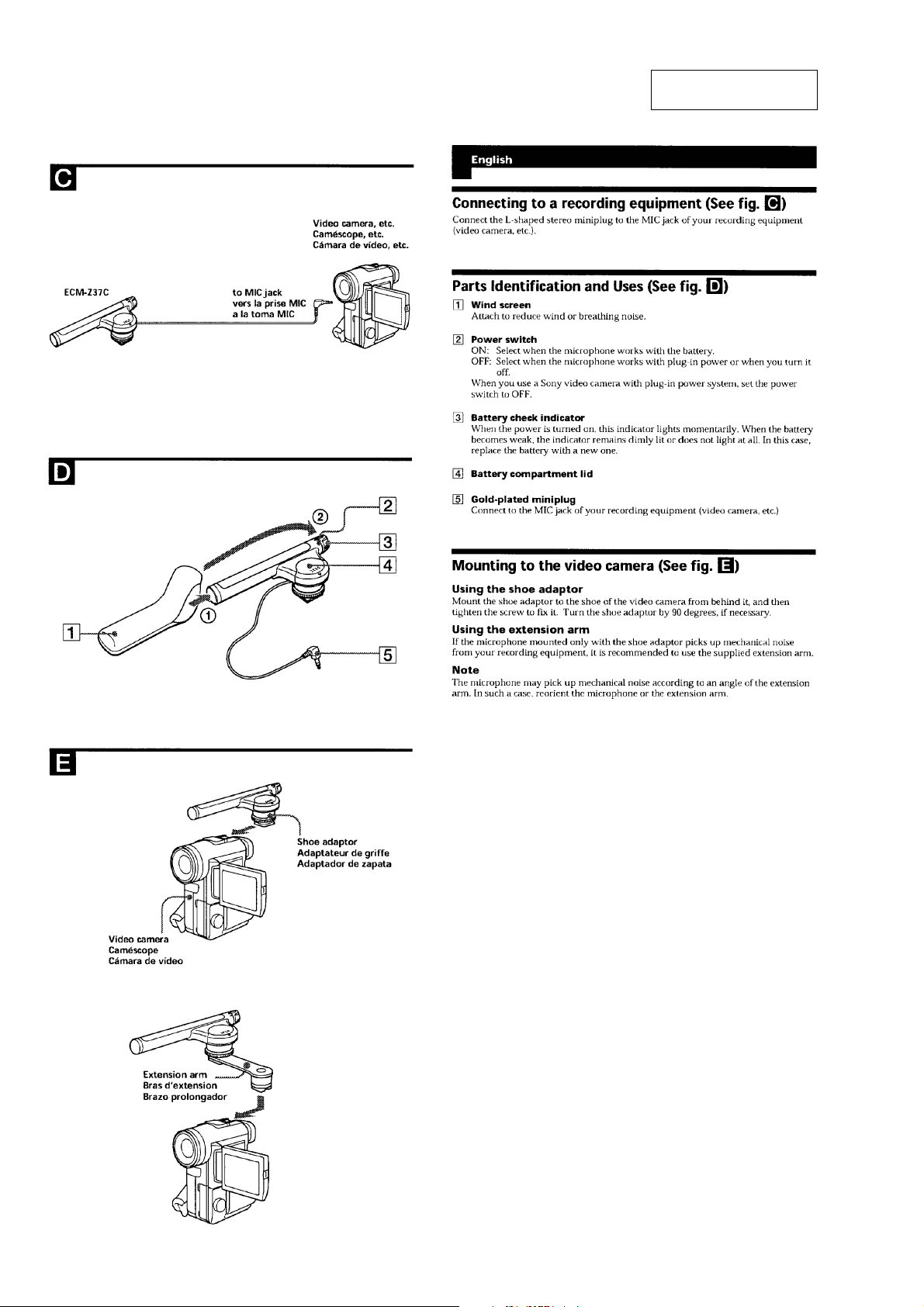
ECM-Z37C
SECTION 1
GENERAL
This section is extracted
from instruction manual.
2
Page 3
SECTION 2
ON
OFF
6 grille assy, front
0 case, lower
8 B 1.7 x 7
4 P 1.4 x 2.5
7 lid battery case
9 case, upper
2 PTPWH 2 x 4
1 cap, switch
3 knob, switch
5 cap, rear
claws
claws
knob, switch cap, switch
Section view
Note for installing the “cap, switch” :
Fit the claws.
claws
claws
Push and
remove.
Section view
Spread and remove.
lid battery case
Note for installing the “knob, switch” :
Position the switch knob with the AMP board switch (SW1)
as shown below.
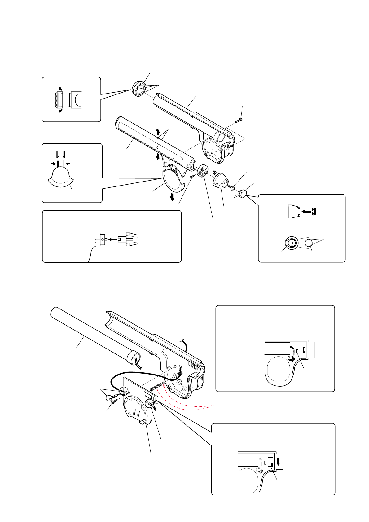
DISASSEMBLY
Note : Follow the disassembly procedure in the numerical order given.
2-1. CASE, UPPER
ECM-Z37C
2-2. MICROPHONE UNIT, AMP BOARD
1 microphone unit
5 Unsolder the
lead wires.
3 P 1.4 x 2.5
2 Unsolder the
4 AMP board
lead wires.
Note for installing the microphone unit:
Arrange the lead wires not to be put on the LED
on the AMP board.
microphone unit
Note: Pay attention to drop of the compression
spring and stainless hall when removing
the AMP board.
Note for installing the AMP board:
Push the AMP board switch (SW1) down to position
the board with the switch knob.
switch (SW1)
LED
3
Page 4

ECM-Z37C
3-1. SCHEMATIC DIAGRAM
SECTION 3
DIAGRAMS
2.4
3
Note:
• All capacitors are in µF unless otherwise noted. pF: µµF
50 WV or less are not indicated except for electrolytics
and tantalums.
• All resistors are in Ω and 1/4 W or less unless otherwise
specified.
• % : indicates tolerance.
• C : panel designation.
• A : B+ Line.
• Power voltage is dc 3V and fed with regulated dc power
supply from battery terminal.
• Voltage is dc with respect to ground under no-signal
conditions.
• Signal path.
F : MIC
2.9
2.9
4
Page 5

3-2. PRINTED WIRING BOARD
R3
C3
R4
R5
C5
C4
RED
BLK
D4
ON
D3
SW1
(POWER)
OFF
ON
-1 -2
BLU
MINI PLUG
(MIC OUT)
FET1
MIC1
MIC UNIT
(CHASSIS)
TO TOP GRILLE
1-679-162-
11
(11)
R2
C6
R1
C1
D1
C2
S
D2
LITHIUM
BATTERY
CR-2025
3V
AMP BOARD (COMPONENT SIDE)
R9
1
A
B
C
D
E
F
2345678
ECM-Z37C
Note:
• X : parts extracted from the component side.
• Y : parts extracted from the conductor side.
z
•
• : Pattern from the side which enables seeing.
• : Pattern of the rear side.
: Through hole.
• Semiconductor
Location
Ref. No. Location
D1 C-6
D2 C-6
D3 A-7
D4 B-7
5
Page 6

ECM-Z37C
NOTE:
• The mechanical parts with no reference
number in the exploded views are not supplied.
• Items marked “*” are not stocked since
they are seldom required for routine service.
Some delay should be anticipated
when ordering these items.
SECTION 4
EXPLODED VIEWS
• Color Indication of Appearance Parts
Example :
KNOB, BALANCE (WHITE) ... (RED)
RR
Parts Color Cabinet’s Color
• Accessories and packing materials are
given in the last of this parts list.
4-1. MAIN SECTION
11
10
9
13
26 14
15
12
31
24
17
20
19
16
18
30
21
28
23
29
22
R9
2
2
6
8
2
7
Ref. No. Part No. Description Remark
* 1 1-679-162-11 AMP BOARD
2 3-686-420-01 SCREW (P1.4X2.5), TAPPING
3 3-222-905-01 CAP, SWITCH
4 3-222-904-01 KNOB, SWITCH
5 3-222-910-01 SPRING, SWITCH
6 3-222-903-01 CAP, REAR
7 3-222-901-01 LID, BATTERY CASE
8 3-222-907-01 HINGE
9 3-222-899-01 CASE, UPPER
10 3-222-909-01 GRILLE, TOP
11 3-222-913-01 SCREEN, TOP
* 12 3-387-142-01 CUSHION (BUTTON)
13 1-418-258-11 MICROPHONE UNIT (including MIC1 and FET1)
14 X-3379-570-1 GRILLE ASSY, FRONT
15 3-222-912-01 SCREEN, FRONT
1
25
5
4
3
27
Ref. No. Part No. Description Remark
17 1-757-041-11 CORD, MICROPHONE
18 3-307-259-11 SPACER (2.6X3.5)
19 3-222-911-01 BRACKET, SHOE
20 X-3379-656-1 HOLDER ASSY, SHOE
21 3-318-203-81 SCREW (B1.7X7), TAPPING
22 3-222-915-01 CUSHION (A)
23 3-302-492-00 SPRING, COMPRESSION
24 3-222-906-01 WINDOW, LED
25 1-550-104-11 HOLDER, BATTERY
26 3-222-914-01 SCREEN, BOTTOM
27 3-313-392-01 SCREW (2X4), + PTPWH
28 7-671-112-11 BALL, STAINLESS (DIA.2.5)
29 7-682-902-11 SCREW +PWH 2.6X5
30 7-627-454-08 SCREW, PRECISION +K 2.6X3.5
31 3-223-917-01 CUSHION (B)
16 3-222-900-01 CASE, LOWER
6
R9 1-249-385-11 CARBON 2.2 5% 1/4W
Page 7

4-2. ARM SECTION
ECM-Z37C
51
52
not
supplied
53
54
not
supplied
55
not
supplied
Ref. No. Part No. Description Remark Ref. No. Part No. Description Remark
51 A-4540-573-A ARM ASSY (EXTENSION ARM)
52 2-509-712-21 SCREW
53 7-621-284-20 SCREW +P 2.6X6
54 2-545-662-01 O RING (P20)
55 A-4521-030-A HOLDER ASSY, SHOE
7
Page 8

ECM-Z37C
SECTION 5
AMP
NOTE:
• Due to standardization, replacements in
the parts list may be different from the
parts specified in the diagrams or the
components used on the set.
• -XX and -X mean standardized parts, so
they may have some difference from the
original one.
• RESISTORS
All resistors are in ohms.
METAL:Metal-film resistor.
METAL OXIDE: Metal oxide-film resistor.
F:nonflammable
Ref. No. Part No. Description Remark
* 1-679-162-11 AMP BOARD
***********
1-550-104-11 HOLDER, BATTERY
< CAPACITOR >
ELECTRICAL PARTS LIST
• CAPACITORS
uF : µF
• COILS
uH : µH
• Items marked “*” are not stocked since
they are seldom required for routine service.
Some delay should be anticipated
when ordering these items.
• SEMICONDUCTORS
In each case, u : µ, for example:
uA.. : µA.. uPA.. : µPA..
uPB.. : µPB.. uPC..: µPC.. uPD.. : µPD..
C1 1-162-964-11 CERAMIC CHIP 0.001uF 10% 50V
C2 1-110-563-11 CERAMIC CHIP 0.068uF 10% 16V
C3 1-110-563-11 CERAMIC CHIP 0.068uF 10% 16V
C4 1-125-839-11 TANTAL. CHIP 47uF 20% 6.3V
C5 1-125-839-11 TANTAL. CHIP 47uF 20% 6.3V
C6 1-127-760-11 CERAMIC CHIP 4.7uF 10% 6.3V
< DIODE >
D1 8-719-976-96 DIODE DTZ4.7C
D2 8-719-049-09 DIODE 1SS367-T3SONY
D3 8-719-072-95 DIODE 015AZ3.9-X-TPL3
D4 8-719-052-72 LED CL-220HR-C (ON)
< RESISTOR >
R1 1-216-827-11 METAL CHIP 3.3K 5% 1/16W
R2 1-216-833-11 METAL CHIP 10K 5% 1/16W
R3 1-216-827-11 METAL CHIP 3.3K 5% 1/16W
R4 1-216-813-11 METAL CHIP 220 5% 1/16W
R5 1-216-833-11 METAL CHIP 10K 5% 1/16W
< SWITCH >
SW1 1-786-043-21 SWITCH, SLIDE (POWER)
*************************************************************
MISCELLANEOUS
***************
13 1-418-258-11 MICROPHONE UNIT (including MIC1 and FET1)
17 1-757-041-11 CORD, MICROPHONE
R9 1-249-385-11 CARBON 2.2 5% 1/4W
*************************************************************
ACCESSORIES & PACKING MATERIALS
********************************
3-222-848-01 SCREEN, WINDOW
3-229-587-11 MANUAL, INSTRUCTION (ENGLISH,FRENCH,
SPANISH)
3-229-587-21 MANUAL, INSTRUCTION (GERMAN,ITALIAN,
PORTUGUESE) (AEP)
3-926-629-02 PORCH, CARRYING
8
Page 9

ECM-Z37C
9
Page 10

ECM-Z37C
REVISION HISTORY
Clicking the version allows you to jump to the revised page.
Also, clicking the version at the upper right on the revised page allows you to jump to the next revised
page.
Ver. Date Description of Revision
1.0 2001. 02 New
10
 Loading...