

Page 1
ECM-330/360
SERVICE MANUAL
Ver 1.0 2000.01
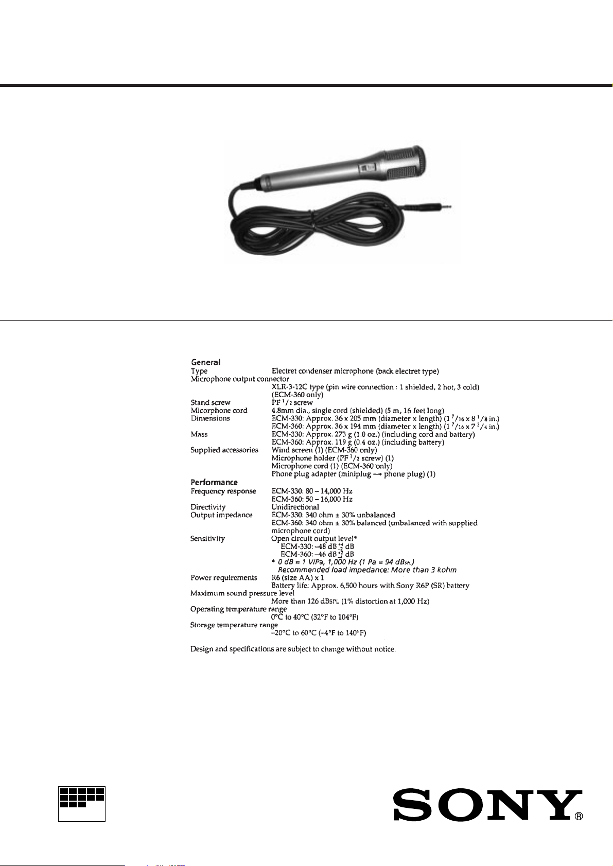
Photo : ECM-330
SPECIFICATIONS
US Model
AEP Model
ECM-330/360
E Model
ECM-330
MICROFILM
ELECTRET CONDENSER MICROPHONE
Page 2
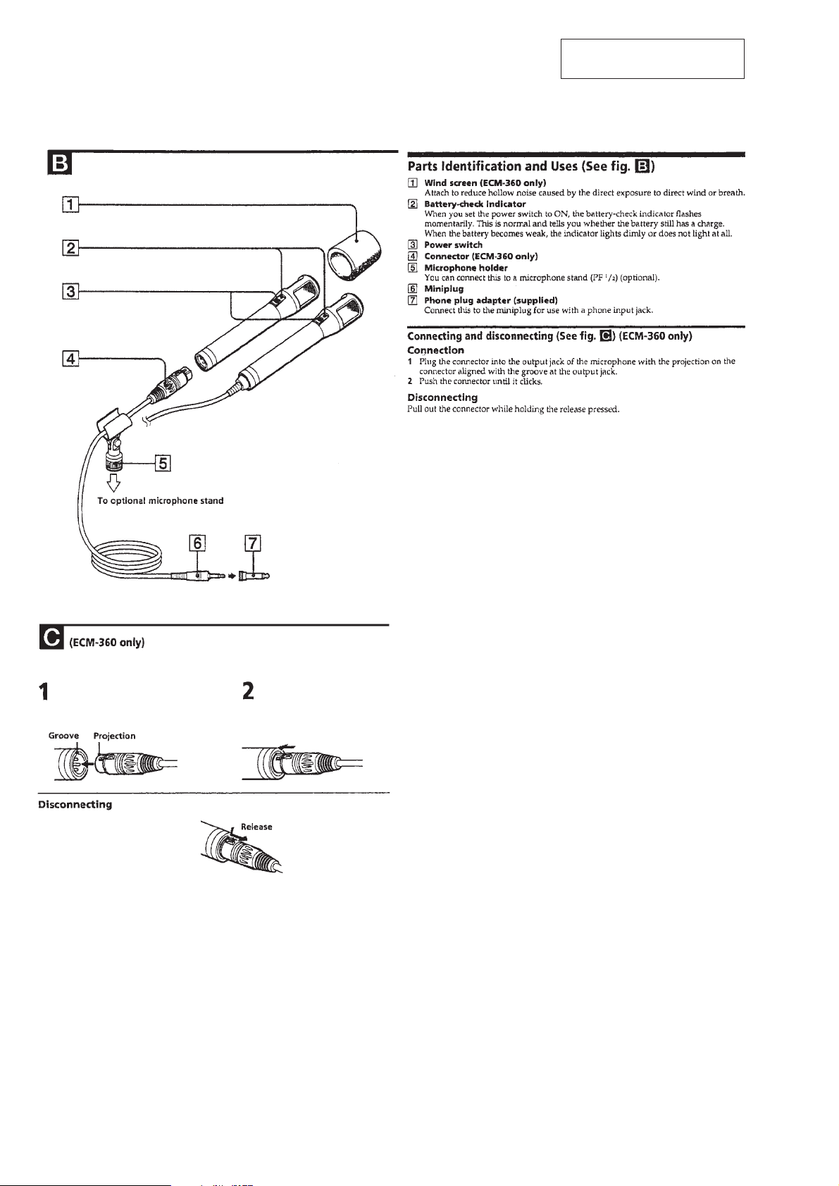
LOCATION AND FUNCTION OF CONTROLS
SECTION 1
GENERAL
This section is extracted from
instruction manual.
– 2 –
Page 3

SECTION 2
DISASSEMBLY
r
The equipment can be removed using the following procedure.
Switch board
Set Case ASSY, microphone
Translation board (ECM-330 only)
Note : Follow the disassembly procedure in the numerical order given.
2-1. CASE ASSY, MICROPHONE
5
Remove solder
Frame
Lead wire (Black)
4
2
1
Grip
2-2. SWITCH BOARD
Case ASSY, microphone
5
Remove solder
Black
White
3
Screw (+KTP 2x5)
Cover (B)
Switch board
Black
Red
4
2
Black
1
Claw
5
Remove solder
White
Red
Black (ECM-360)/White (ECM-330)
White (ECM-360 only)
Orange
6
Spring, ground
1
Claw
Frame
– 3 –
3
Claws
1
Claws
Page 4

2-3. TRANSLATION BOARD (ECM-330 ONLY)
Cover (A)
5
Remove solder
Orange
1
White
Claw
2
3
Translation board
Core wire
Ground wire
6
Remove
solder
4
1
Claw
Sheet, blind
8
Frame
Bushing holder
7
Claw
7
Claw
Bushing
Plug (P1)
– 4 –
Page 5

3-1. PRINTED WIRING BOARDS
1
A
MIC1
B
C
02
Q1
(CASE)
D
RED
FB1
WHT
S
BLK
2
[SWITCH BOARD] (SIDE A)
BLK
[SWITCH BOARD] (SIDE B)
ECM-330/360
SECTION 3
DIAGRAMS
3 4 5 6 7 8 9
OPEN:ECM-360
TAP1
SHORT:ECM-330
D1
WHT
BLK
RED
C3
D2
C1
ON
C4
R1
R2
(IEC DESIGNATION R6)
TAP1
1-675-789-
DRY BATTERY
SIZE "AA"
1PC, 1.5V
S1
t
ON
OFF
1-675-789-
(GRIP)
ECM-360
C2
WHT(ECM-330)
BLK(ECM-360)
WHT
ORG
11
(11)
GRN
BLU
BLK
WHT
YEL
RED
11
(11)
ECM-360
CN1
BLK
12
3
12
3
ORG
WHT
T1
P1
(OUTPUT)
ECM-330
[TRANSLATION BOARD] (SIDE A)
WHT
ORG
1-675-790-
[TRANSLATION BOARD] (SIDE B)
1-675-790-
11
(11)
11
(11)
P1
(OUTPUT)
z
Semiconductor
Location
Ref. No. Location
D1 A-3
D2 A-2
Q1 A-1
Note on Printed Wiring Boards:
Note:
• X : parts extracted from the component side.
• z : Through hole.
• b : Pattern from the side which enables seeing.
(The other layers' patterns are not indicated.)
Caution:
Pattern face side: Parts on the pattern face side seen from the
(Side B) pattern face are indicated.
Parts face side: Parts on the parts face side seen from the
(Side A) parts face are indicated.
3-2. SCHEMATIC DIAGRAM
Note on Schematic Diagram:
Note:
• All capacitors are in µF unless otherwise noted. pF: µµF
50 WV or less are not indicated except for electrolytics
and tantalums.
• All resistors are in Ω and 1/
specified.
4
W or less unless otherwise
• U : B+ Line.
• Power v oltage is dc 1.5V and fed with regulated dc power
supply from battery terminal.
• Voltages are dc with respect to ground under no-signal
conditions.
• Signal path.
F
– 5 – – 6 –
Page 6

SECTION 4
EXPLODED VIEW
ECM-330/360
SWITCH TRANSLATION
SECTION 5
ELECTRICAL PARTS LIST
NOTE :
• -XX, -X mean standardized parts, so they
may have some difference from the original
one.
• Items marked “ * ”are not stocked since they
are seldom required for routine service. Some
delay should be anticipated when ordering
these items.
9
8
7
• The mechanical parts with no reference
number in the exploded views are not
supplied.
• Hardware (# mark) list and accessories and
packing materials are given in the last of this
parts list.
17
10
15
11
T1
12
13
14
16
supplied
wtih CN1
18
ECM-330
CN1
22
20
21
P1
P1
ECM-360
NOTE :
• Due to standardization, replacements in the
parts list may be different from the parts
specified in the diagrams or the components
used on the set.
• -XX, -X mean standardized parts, so they
may have some difference from the original
one.
• RESISTORS
All resistors are in ohms
METAL : Metal-film resistor
METAL OXIDE :Metal oxide-film resistor
F : nonflammable
• Items marked “ * ”are not stocked since
they are seldom required for routine service.
Some delay should be anticipated when
ordering these items.
Ref. No. Part No. Description Remark Ref. No. Part No. Description Remark
* 1-675-789-11 SWITCH BOARD
*************
< CAPACITOR >
C1 1-127-569-11 TANTAL. CHIP 100uF 20% 4V
C2 1-127-569-11 TANTAL. CHIP 100uF 20% 4V
C3 1-163-009-11 CERAMIC CHIP 0.001uF 10% 50V
C4 1-163-009-11 CERAMIC CHIP 0.001uF 10% 50V
< DIODE >
D1 8-719-064-07 LED SML-310LTT86 (ON)
D2 8-719-072-95 DIODE 015AZ3.9-X-TPL3
< RESISTOR >
• SEMICONDUCTORS
In each case, u : µ , for example :
uA.... : µ A.... , uPA.... : µ PA....
uPB.... : µ PB.... , uPC.... : µ PC....
uPD.... : µ PD....
• CAPACITORS
uF : µ F
• COILS
uH : µ H
When indicating parts by reference number, please include the board.
ACCESSORIES & PACKING MATERIALS
*******************************
1-766-783-11 ADAPTOR, PLUG (ECM-330:US,E,ECM-360)
1-791-751-11 CORD, MICROPHONE (DIA. 4.8) (ECM-330)
1-791-752-11 CORD, MICROPHONE (DIA. 4.8) (ECM-360)
2-100-951-04 ADAPTER, SCREW, STAND (SAD-34)
2-100-952-00 ADAPTER, SCREW, STAND (SAD-35)
2-524-919-11 SCREEN, WINDOW (ECM-360)
3-868-224-11 MANUAL, INSTRUCTION (ENGLISH,FRENCH,
SPANISH,GERMAN,ITALIAN,PORTUGUESE)
A-4540-622-A HOLDER ASSY (E), MICROPHONE
Q1
4
FB1
1
2
19
ECM-330
3
MIC1
5
6
Ref. No. Part No. Description Remark Ref. No. Part No. Description Remark
* 1 2-545-977-01 FRAME
* 2 2-545-970-01 SPRING, GROUND
* 3 2-532-219-00 TERMINAL, GROUND
4 2-523-713-00 TERMINAL
5 7-685-203-19 SCREW +KTP 2X5 TYPE2 SLIT
6 A-4540-609-A CASE ASSY, MICROPHONE
* 7 1-675-789-11 SWITCH BOARD
8 2-545-976-01 COVER (B)
9 2-545-972-01 LENS, LED
10 2-545-975-01 COVER, SWITCH
11 2-545-974-01 KNOB, SWITCH
12 9-911-815-02 CUSHION
13 2-545-960-01 TERMINAL (A), BATTERY
14 2-545-961-01 TERMINAL (B), BATTERY
15 2-545-973-01 COVER (A)
* 16 1-675-790-11 TRANSLATION BOARD (ECM-330)
17 2-545-967-01 GRIP
18 2-545-968-01 LABEL, MODEL NUMBER (ECM-360)
18 2-545-978-01 LABEL, MODEL NUMBER (ECM-330)
19 2-545-971-01 SHEET, BLIND
* 20 2-513-925-11 CASE, CONNECTOR (ECM-360)
21 2-545-980-01 HOLDER, BUSHING (ECM-330)
22 2-545-979-01 BUSHING (ECM-330)
* CN1 1-563-175-51 CANNON XLR3-14 PIN INSERT (ECM-360)
FB1 1-543-298-11 BEAD, FERRITE
MIC1 8-814-289-90 CAPSULE, MICROPHONE CU14-03
P1 1-791-751-11 CORD, MICROPHONE (DIA. 4.8) (ECM-330)
P1 1-791-752-11 CORD, MICROPHONE (DIA. 4.8) (ECM-360)
Q1 8-729-037-43 TRANSISTOR 2SK1578-A
T1 1-431-068-11 TRANSFORMER, OUTPUT
R1 1-216-836-11 METAL CHIP 18K 5% 1/16W
R2 1-216-815-11 METAL CHIP 330 5% 1/16W
< SWITCH >
S1 1-571-738-11 SWITCH, SLIDE (ON/OFF)
**************************************************************
* 1-675-790-11 TRANSLATION BOARD (ECM-330)
******************
**************************************************************
MISCELLANEOUS
**************
* CN1 1-563-175-51 CANNON XLR3-14 PIN INSERT (ECM-360)
FB1 1-543-298-11 BEAD, FERRITE
MIC1 8-814-289-90 CAPSULE, MICROPHONE CU14-03
P1 1-791-751-11 CORD, MICROPHONE (DIA. 4.8) (ECM-330)
P1 1-791-752-11 CORD, MICROPHONE (DIA. 4.8) (ECM-360)
Q1 8-729-037-43 TRANSISTOR 2SK1578-A
T1 1-431-068-11 TRANSFORMER, OUTPUT
**************************************************************
– 7 –
9-927-196-11
Sony Corporation
Personal Audio Division Company
– 8 –
Printed in Japan © 2000.1
2000A0263-1
Published by General Engineering Dept.
 Loading...