

Sony D-E551, D-E555, D-E556CK, D-E771, E776CK Service Manual
...
D-E551/E555/E556CK
Q
Q
3
7
6
3
1
5
1
5
0
SERVICE MANUAL
Ver 1.0 1999. 02
TEL 13942296513 QQ 376315150 892498299
4
2
9
8
Model Name Using Similar Mechanism D-E700/E705
CD Mechanism Type CDM-2911EBA
Optical Pick-Up Name DAX-11E
9
2
8
US Model
D-E551/E555/E556CK
AEP Model
UK Model
D-E555/E556CK
9
9
TEL 13942296513 QQ 376315150 892498299
TEL
13942296513
SPECIFICATIONS
6
7
3
Q
Q
3
1
5
1
5
0
8
9
2
4
9
8
2
9
9
w
w
MICROFILM
w
.
xia
COMPACT DISC COMPACT PLAYER
o
y
u
1
6
3
.
c
o
m
TABLE OF CONTENTS
7
Q
Q
1. SERVICING NOTES ............................................... 3
2. GENERAL ................................................................... 4
3. DISASSEMBLY ......................................................... 7
4. SERVICE MODE...................................................... 8
5. ELECTRICAL ADJUSTMENTS......................... 9
6. DIAGRAMS
6-1. Block Diagram – MAIN Section – ................................. 13
6-2. Block Diagram – POWER SUPPLY Section – .............. 17
6-3. IC Pin Function Description ........................................... 19
TEL 13942296513 QQ 376315150 892498299
6-4. Printed Wiring Board ...................................................... 22
6-5. Schematic Diagram ......................................................... 25
7. EXPLODED VIEWS ................................................ 34
8. ELECTRICAL PARTS LIST ............................... 37
3
6
3
1
5
1
5
This appliance is classified as a CLASS 1 LASER product.
The CLASS 1 LASER PRODUCT MARKING is located on
0
the rear exterior.
CAUTION
Use of controls or adjustments or performance of procedures
other than those specified herein may result in hazardous radiation exposure.
8
9
2
4
9
8
2
9
9
TEL 13942296513 QQ 376315150 892498299
TEL
13942296513
8
9
4
2
9
8
0
5
1
5
1
3
6
7
3
Q
Q
Flexible Circuit Board Repairing
• Keep the temperature of the soldering iron around 270 ˚C during repairing.
• Do not touch the soldering iron on the same conductor of the
circuit board. (within 3 times)
• Be careful not to apply force on the conductor when soldering
or unsoldering.
Notes on chip component replacement
• Never reuse a disconnected chip component.
• Notice that the minus side of a tantalum capacitor may be damaged by heat.
2
9
9
w
w
w
.
xia
SAFETY-RELATED COMPONENT WARNING!!
COMPONENTS IDENTIFIED BY MARK ! OR DOTTED
LINE WITH MARK ! ON THE SCHEMATIC DIAGRAMS
AND IN THE PARTS LIST ARE CRITICAL TO SAFE
o
y
u
– 2 –
OPERATION. REPLACE THESE COMPONENTS WITH
1
6
SONY PARTS WHOSE PART NUMBERS APPEAR AS
SHOWN IN THIS MANUAL OR IN SUPPLEMENTS PUBLISHED BY SONY.
3
.
c
o
m
SECTION 1
SERVICING NOTES
NOTES ON HANDLING THE OPTICAL PICK-UP
Q
TEL 13942296513 QQ 376315150 892498299
BLOCK OR BASE UNIT
Q
The laser diode in the optical pick-up block may suffer electrostatic breakdown because of the potential difference generated by
the charged electrostatic load, etc. on clothing and the human body .
During repair, pay attention to electrostatic breakdown and also
use the procedure in the printed matter which is included in the
repair parts.
The flexible board is easily damaged and should be handled with
care.
Befor Replacing the Optical Pick-Up Block
Please be sure to check thoroughly the parameters as par the “Optical Pick-Up Block Checking Procedures” (Part No.: 9-960-027-
11) issued separately before replacing the optical pick-up block.
Note and specifications required to check are given below.
• FOK output: IC501 !™ pin
When checking FOK, remove the lead wire to disc motor.
• S curve P-to-P value: 0.6 to 1.8 Vp-p IC501 #¡ pin
When checking S curve P-to-P value, remove the lead wire to
disc motor.
• RF signal P-to-P value: 0.8 to 1.2 Vp-p
• Traverse signal P-to-P value: 1.2 Vp-p
• The repairing grating holder is impossible.
3
7
6
3
1
5
1
5
0
Precautions for Checking Emission of Laser Diode
Laser light of the equipment is focused by the object lens in the
optical pick-up so that the light focuses on the reflection surface
of the disc. Therefore, be sure to keep your eyes more then 30 cm
apart from the object lens when you check the emission of laser
diode.
Laser Diode Checking Methods
During normal operation of the equipment, emission of the laser
diode is prohibited unless the upper panel is closed while turning
ON the S801. (push switch type)
The following two checking methods for the laser diode are operable.
• Method (In the service mode or normal operation):
Emission of the laser diode is visually checked.
1. Open the upper lid.
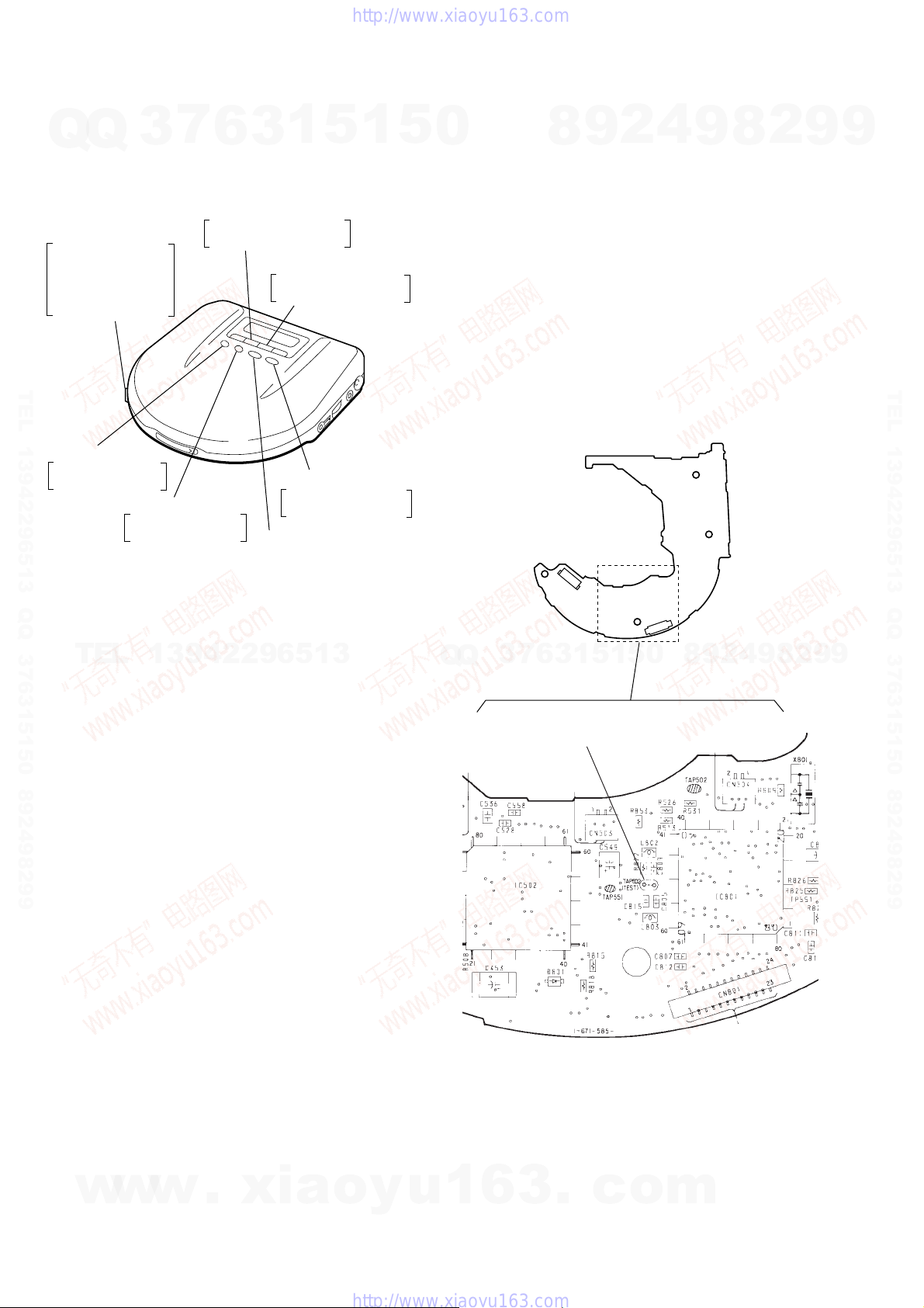
2. Push the S801 as shown in Fig. 1.
3. Press the ^ key.
4. Check the object lens for confirming normal emission of the
laser diode. If not emitting, there is a trouble in the automatic
power control circuit or the optical pick-up.
During normal operation, the laser diode is turned ON about
2.5 seconds for focus searching.
8
9
2
4
9
8
2
9
9
TEL 13942296513 QQ 376315150 892498299
TEL
13942296513
Q
Q
3
7
6
9
8
0
5
1
5
1
3
S801
Fig. 1 Method to push the S801
2
4
9
8
2
9
9
w
w
w
.
xia
o
y
u
1
6
3
– 3 –
.
c
o
m
SECTION 2
GENERAL
7
Q
Q
TEL 13942296513 QQ 376315150 892498299
3
6
3
1
5
1
5
0
8
This section is extracted from
instruction manual.
4
9
2
9
8
2
9
9
TEL 13942296513 QQ 376315150 892498299
TEL
13942296513
Q
Q
3
7
6
3
1
5
1
5
0
8
9
2
4
9
8
2
9
9
w
w
w
.
xia
o
y
u
1
6
3
– 4 –
.
c
o
m
7
Q
Q
TEL 13942296513 QQ 376315150 892498299
3
6
3
1
5
1
5
0
8
9
2
4
9
8
2
9
9
TEL 13942296513 QQ 376315150 892498299
TEL
13942296513
Q
Q
3
7
6
3
1
5
1
5
0
8
9
2
4
9
8
2
9
9
w
w
w
.
xia
o
y
u
1
6
3
– 5 –
.
c
o
m
7
Q
Q
TEL 13942296513 QQ 376315150 892498299
3
6
3
1
5
1
5
0
8
9
2
4
9
8
2
9
9
TEL 13942296513 QQ 376315150 892498299
TEL
13942296513
Q
Q
3
7
6
3
1
5
1
5
0
8
9
2
4
9
8
2
9
9
w
w
w
.
xia
o
y
u
1
6
3
– 6 –
.
c
o
m

Q
Note: Follow the disassembly procedure in the numerical order given.
7
Q
3
CABINET (LOWER)
5
6
cabinet (lower)
3
1
5
1
five screws
(2
1
×
8)
5
SECTION 3
DISASSEMBLY
0
8
4
9
two claws
2
4
8
9
2
Open the battery case lid.
2
9
9
TEL 13942296513 QQ 376315150 892498299
4
two claws
INSTALLATION MAIN BOARD
On installation MAIN board adjust the
TEL
13942296513
S301, 803, 804, and knob (H-R, A VLS).
S804
Q
Q
3
7
3
two claws
4
2
9
8
0
5
1
5
1
3
6
Note:Take care not to allow the rechargeable
battery detection plate to ride on the mold
of the bottom plate.
S301
S803
9
8
2
9
TEL 13942296513 QQ 376315150 892498299
9
w
w
knob (H-R)
w
.
xia
o
y
u
1
6
3
– 7 –
.
c
knob (AVLS)
o
m
]
SECTION 4
SERVICE MODE
Service Mode (Service program)
The equipment is provided with a service program built in the
Q
Q
microcomputer, like conventional models.
Service program operation methods are described in the following.
HOLD
c
Be sure to turn OFF
the HOLD switch
(If ON, all the LCD
indication and
LED are light up)
TEL 13942296513 QQ 376315150 892498299
=
(FR)
The optical pick-up
is moved inwardly
+
7
3
(FF)
The optical pick-up
is moved outwardly
6
PLAY MODE
Tracking servo and sled
servo are turned ON
1
5
3
REPEAT/ENTER
Tracking gain-up mode
while pressing
^
(PLAY/PAUSE)
Focus is tuned ON to
effect draw-in mode
p
(STOP)
[All servos are turned OFF
1
5
4. By pressing the ^ k ey , focus is turned ON from focus searching while entering CLV-S. (draw-in mode)
0
Without disc, focus searching is repeated continuously.
5. By pressing the PLAY MODE key, tracking servo, sled servo
and CLV-A (servo in PLAY) are turned ON.
6. When step 4 and 5 are performed, playing begins. No muting
is ON in the service mode.
7. By pressing the p key, all servos (focus, tracking and sled)
are turned OFF . Ho we ver, the disc motor revolv es for a while
by inertia.
• Step 3 (Resetting of service mode)
1. Be sure to disconnect the external power supply and remove
the solder bridge at the TEST terminals connected before in
setting.
2. The set thus becomes available for normal operation.
– MAIN BOARD (Side A) –
8
9
2
4
9
8
2
9
9
TEL 13942296513 QQ 376315150 892498299
Descriptions in [ ] indicate major operations in the service
mode. For more informatrion, see Step 2.
Fig. 1 Layout of each key
TEL
• Step 1 (Service mode setting methods)
1. Turn OFF the HOLD switch with external power supply disconnected. (power is not applied to the set)
2. Solder across the TEST terminals (TAP802). (pin %¢, IC801
(ESPSL/TEST) is grounded)
3. Connect an external power supply.
Thus, the set is switched to the service mode.
• Step 2 (Operation in the service mode)
1. Once the service mode is ef fected, the LCD displays 5 indications each of which is repeatedly displayed.
However , the following operations can be acti vated e ven if LCD
indication is effected.
2. By pressing the + or = ke y, the optical pick-up is movable inwardly or outwardly . Howev er, if this is acti vated, tracking servo and sled servo are turned OFF, so it can be turned
ON by pressing the PLAY MODE key if required.
3. By pressing the REPEAT/ENTER key, the tracking gain-up
mode becomes active.
13942296513
Q
Q
3
7
6
1
3
TAP802
(TEST)
5
1
5
0
8
9
2
4
9
8
2
9
9
w
w
w
.
xia
o
y
u
1
6
3
– 8 –
Fig. 2 Location of Test terminal
.
c
o
m
 Loading...