

Page 1

CAPSULE UNIT
CU-F780
CU-G780
CU-E700
CU-E672
CU-F117
SERVICE MANUAL
1st Edition
Page 2

! WARNING
This manual is intended for qualified service personnel only.
To reduce the risk of electric shock, fire or injury, do not perform any servicing other than that
contained in the operating instructions unless you are qualified to do so. Refer all servicing to
qualified service personnel.
! WARNUNG
Die Anleitung ist nur für qualifiziertes Fachpersonal bestimmt.
Alle W artungsarbeiten dürfen nur von qualifiziertem Fachpersonal ausgeführt werden. Um die
Gefahr eines elektrischen Schlages, Feuergefahr und V erletzungen zu vermeiden, sind bei
Wartungsarbeiten strikt die Angaben in der Anleitung zu befolgen. Andere als die angegeben
Wartungsarbeiten dürfen nur von Personen ausgeführt werden, die eine spezielle Befähigung
dazu besitzen.
! A VERTISSEMENT
Ce manual est destiné uniquement aux personnes compétentes en charge de l’entretien. Afin
de réduire les risques de décharge électrique, d’incendie ou de blessure n’effectuer que les
réparations indiquées dans le mode d’emploi à moins d’être qualifié pour en effectuer d’autres.
Pour toute réparation faire appel à une personne compétente uniquement.
CU-F780/G780/E700/E672/F117
Page 3

Table of Contents
1. Operating Instructions.....................................................................1-1
2. CU-F780/CU-G780
2-1. Service Overview ........................................................................................2-1
2-1-1. Notes on Attaching the CN-2089 Board .................................... 2-1
2-2. Board Layout...............................................................................................2-1
2-3. Schematic Diagrams....................................................................................2-2
CN-2089...................................................................................................... 2-2
2-4. Spare Parts...................................................................................................2-3
2-4-1. Notes on Repair Parts................................................................. 2-3
2-4-2. Exploded Views and Parts List ..................................................2-4
2-4-3. Electrical Parts List ....................................................................2-4
2-4-4. Supplied Accessories ................................................................. 2-4
3. CU-E700
3-1. Service Overview ........................................................................................3-1
3-1-1. Notes on Attaching the CN-2089 Board .................................... 3-1
3-2. Board Layout...............................................................................................3-1
3-3. Schematic Diagrams....................................................................................3-2
CN-2089...................................................................................................... 3-2
MA-56 .........................................................................................................3-2
3-4. Spare Parts...................................................................................................3-3
3-4-1. Notes on Repair Parts................................................................. 3-3
3-4-2. Exploded Views and Parts List ..................................................3-4
3-4-3. Electrical Parts List ....................................................................3-4
3-4-4. Supplied Accessories ................................................................. 3-4
4. CU-E672
4-1. Service Overview ........................................................................................4-1
4-1-1. Disassembly ...............................................................................4-1
4-1-2. Notes on Attaching the CN-2089 Board .................................... 4-3
4-2. Board Layout...............................................................................................4-3
4-3. Schematic Diagrams....................................................................................4-4
CN-2089...................................................................................................... 4-4
MA-109 .......................................................................................................4-4
4-4. Spare Parts...................................................................................................4-5
4-4-1. Notes on Repair Parts................................................................. 4-5
4-4-2. Exploded Views and Parts List ..................................................4-6
CU-F780/G780/E700/E672/F117
1
Page 4

4-4-3. Electrical Parts List ....................................................................4-6
4-4-4. Supplied Accessories ................................................................. 4-6
5. CU-F117
5-1. Service Overview ........................................................................................5-1
5-1-1. Notes on Attaching the CN-2089 Board .................................... 5-1
5-2. Board Layout...............................................................................................5-1
5-3. Schematic Diagrams....................................................................................5-2
CN-2089 ......................................................................................................5-2
5-4. Spare Parts...................................................................................................5-3
5-4-1. Notes on Repair Parts................................................................. 5-3
5-4-2. Exploded Views and Parts List ..................................................5-4
5-4-3. Electrical Parts List ....................................................................5-4
5-4-4. Supplied Accessories ................................................................. 5-4
2
CU-F780/G780/E700/E672/F117
Page 5
Section 1
Operating Instructions
Reprinted from the
operating instructions
3-205-156-02 (1)
Capsule Unit
Operating Instructions
CU-F780
CU-G780
CU-E700
CU-E672
CU-F117
Sony Corporation © 2000
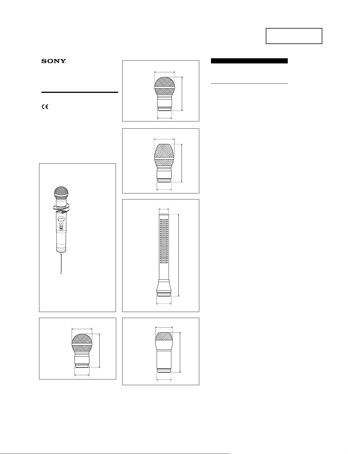
Mounting on the transmitter
Turn the capsule unit in the direction of the arrow as shown below.
Be sure to securely mount the capsule unit on the transmitter.
Printed in Japan
Microphone capsule unit
B CU-G780
Dimension: unit in mm
Mass:180g
C CU-E700
Dimension: unit in mm
Mass:170g
E CU-E672
ø51
ø37
ø24
ø51
ø37
English
The CU-F780/CU-G780/CU-E700/CU-E672/CU-F117 are the
Microphone Capsule Units designed for the WRT-847A/WRT847B Sony UHF synthesized transmitter unit to be used in a Sony
UHF synthesized wireless microphone system.
Specifications
90
98
Type CU-F780 / CU-G780 / CU-F117
Frequency response CU-F780 : 50 Hz to 18,000 Hz
Directivity CU-F780 / CU-G780 / CU-E700 :
Sensitivity CU-F780 : –55 dB (1.78 mV)
General
Dimensions and mass See figures A to E.
Operating temperature
Storage temperature –20 °C to +60 °C (–4 °F to +140 °F)
Supplied accessories
Operating Instructions (1)
Wind screen (supplied only for CU-E672 / CU-F117) (1)
Design and specifications are subject to change without notice.
Dynamic microphone capsule
CU-E700 / CU-E672
Electret condenser microphone
capsule
CU-G780: 50 Hz to 20,000 Hz
CU-E700 : 50 Hz to 18,000 Hz
CU-E672 : 50 Hz to 16,000 Hz
CU-F117 : 50 Hz to 15,000 Hz
See frequency response curves on the other
side of the sheet.
Uni-directional (Super cardioid)
CU-E672 :
Uni-directional (Hyper cardioid)
CU-F117 :
Omni-directional
See direcivity curves on the other side of
the sheet.
CU-G780: –55 dB (1.78 mV)
CU-E700 : –55 dB (1.78 mV)
CU-E672 : –45 dB (5.62 mV)
CU-F117 : –52 dB (2.51 mV)
0 °C to +50 °C (+32 °F to +122 °F)
(0 dB= 1V/Pa, 1kHz)
Transmitter WRT-847A/847B
In the figure, the CU-F780 capsule unit is mounted
WRT-847A/847B transmitter (optional) as an
A CU-F780
Dimension: unit in mm
Mass:180g
ø51
ø37
example.
on the
172
Dimension: unit in mm
Mass:150g
E CU-F117
90
Dimension: unit in mm
Mass:170g
ø37
ø44
105
ø37
CU-F780/G780/E700/E672/F117
1-1
Page 6
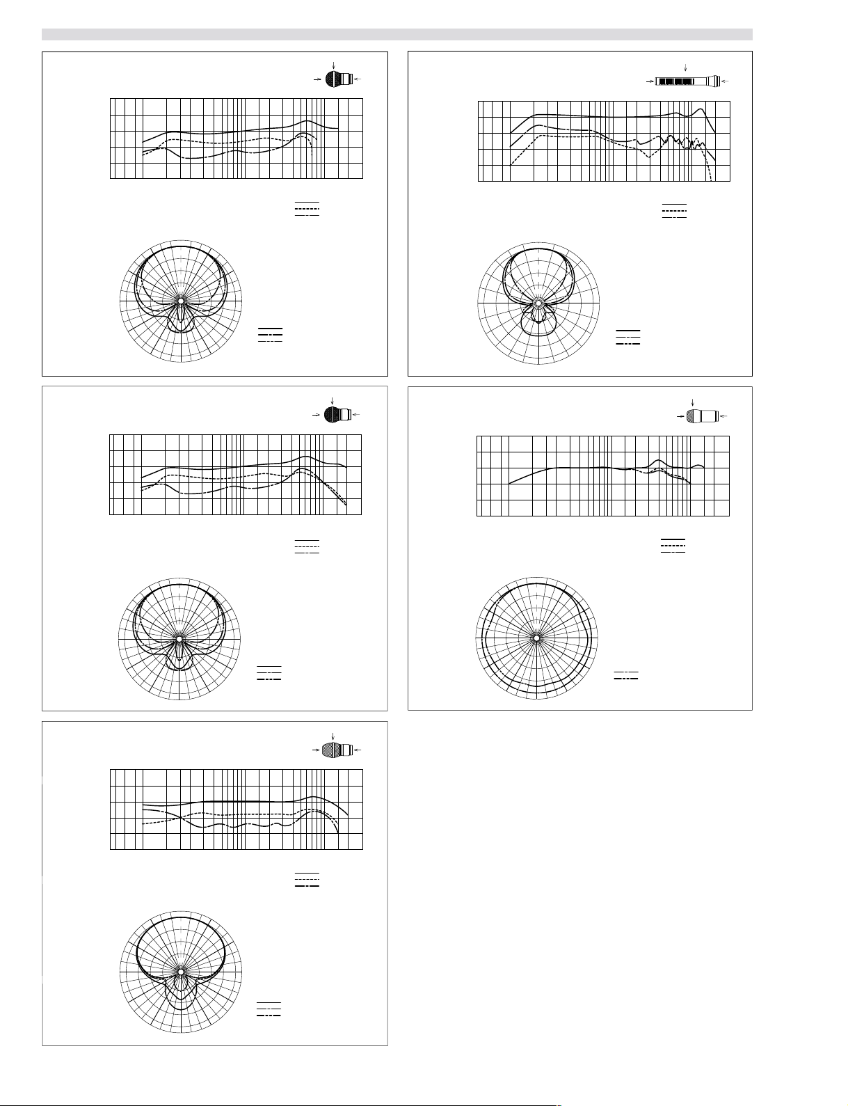
Frequency response and directivity
0
90
180
0
90
180
90˚
180˚0˚
˚
˚
˚
90˚
180˚0˚
˚
˚
˚
CU-E672
Uni-directional
CU-F117
Response
Omni-directional
20
10
0
-10
-20
Response
(dB)
-30
20 50 100 200 500 1k 20k Hz2k 5k 10k
45˚
60˚
75˚
90˚
105˚
120˚
135˚
20
10
0
-10
-20
(dB)
-30
20 50 100 200 500 1k 20k Hz2k 5k 10k
60˚
90˚
CU-F780
Uni-directional
CU-G780
Uni-directional
20
10
0
-10
-20
Response
(dB)
-30
20 50 100 200 500 1k 20k Hz2k 5k 10k
60˚
90˚
120˚
20
10
0
-10
-20
Response
(dB)
-30
20 50 100 200 500 1k 20k Hz2k 5k 10k
60˚
90˚
150˚
30˚
30˚
Frequency (Hz)
0˚
0dB
-5
-10
-15
-20
180˚
Frequency (Hz)
0˚
0dB
-5
-10
-15
-20
30˚
60˚
90˚
120˚
150˚
30˚
60˚
90˚
100 Hz
1 kHz
6 kHz
30˚
150˚
30˚
Frequency (Hz)
15˚
0dB
-10
-15
-20
165˚
180˚
0˚
0dB
-5
-10
-15
-20
0˚
15˚
-5
165˚
Frequency (Hz)
150˚
30˚
90˚
180˚0˚
0
˚
90
˚
180
˚
30˚
45˚
60˚
75˚
90˚
105˚
250 Hz
1 kHz
120˚
135˚
4 kHz
90˚
180˚0˚
0
˚
90
˚
180
˚
60˚
90˚
CU-E700
Uni-directional
1-2
120˚
150˚
20
10
0
-10
-20
Response
(dB)
-30
20 50 100 200 500 1k 20k Hz2k 5k 10k
60˚
90˚
120˚
150˚
Frequency (Hz)
0˚
30˚
0dB
-5
-10
-15
-20
180˚
150˚
120˚
180˚
30˚
60˚
90˚
120˚
150˚
100 Hz
1 kHz
6 kHz
200 Hz
1 kHz
5 kHz
0
90
180
120˚
150˚
180˚
90˚
180˚0˚
˚
˚
˚
150˚
120˚
100 Hz / 1 kHz
6 kHz
CU-F780/G780/E700/E672/F117
Page 7

2. CU-F780/CU-G780
2-1. Service Overview
2-1-1. Note s o n A t t a c h i n g t h e C N -2089 Board
B 2x4
(three)
<Top View>
CN-2089
board
SONY logo
Grip 1
Place the PC board in the unit
with the SONY logo facing you,
and align the board so that the
nub on the board fits into the
small indentation on the unit.
Grip 1
2-2. Board Layout
DM UNIT
RED
WHT
BLK
R1
27 k
RED
WHT
CN-2089 Board
R2
39 k
CU-F780/G780/E700/E672/F117
2-1
Page 8
CN-2089
1
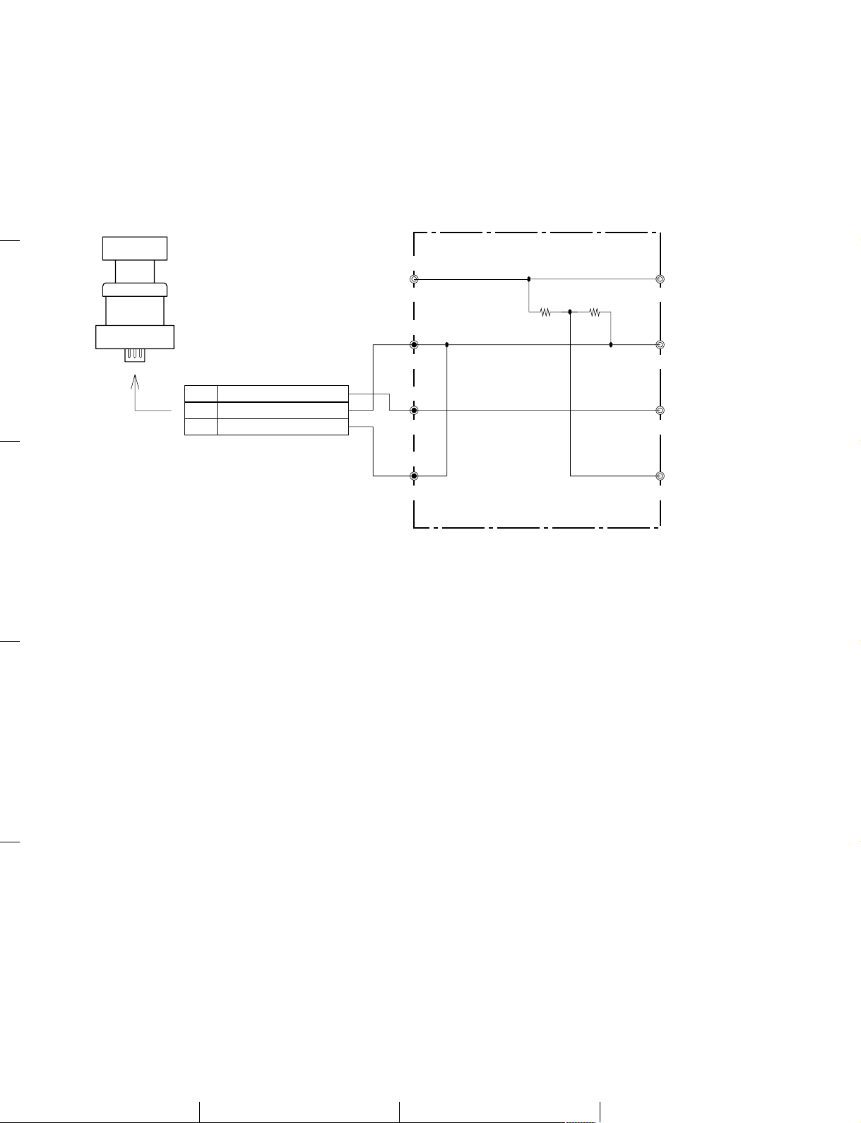
2-3. Schematic Diagrams
ECM-WHT
DM-UNIT
2
1
2
3
TO UNIT
CN1
RED
BLK
WHT
VCC
BLK
GND
RED
HOT
D-WHT
COLD
R101
27k
R102
39k
ECM-VCC(5.8V)
GND
TO CN-2055
HOT
CU-ID
CN-2089
3
CN-2089
4
5
2-2
CU-F780/G780/E700/E672/F117
AB C D
Page 9

2-4. Spare Parts
2-4-1. Notes on Repair Parts
1. Safety Related Components Warning
w
Components marked ! are critical to safe operation.
Therefore, specified parts should be used in the case of
replacement.
2. Standardization of Parts
Some repair parts supplied by Sony differ from those
used for the unit. These are because of parts commonality and improvement.
Parts list has the present standardized repair parts.
3. Stock of Parts
Parts marked with “o” at SP (Supply Code) column of
the spare parts list may not be stocked. Therefore, the
delivery date will be delayed.
4. Harness
Harnesses with no part number are not registered as
spare parts.
In need of repair, get components shown in the list and
repair using them.
CU-F780/G780/E700/E672/F117
2-3
Page 10

2-4-2. Exploded Views and Parts List
2
4
5
1
6
B 2x4
No. Part No. SP Description
3
1 A-8265-752-B s DM UNIT ASSY (V4.1) (For CU-F780)
A-8327-861-A s CAPSULE (V4.01) ASSY, DM PS (For CU-G780)
2 A-8327-860-A s MOUNTED CIRCUIT BOARD, CN-2089
3 X-3608-171-1 s ASSY, CAGE (RS) (For CU-G780)
X-3678-174-2 s CAGE ASSY (For CU-F780)
4 1-961-058-11 o HARNESS, SUB (B)
5 3-631-750-01 o RING
6 3-682-258-01 s SCREEN
2-4-3. Electrical Parts List
------------CN-2089 BOARD
2-4-4. Supplied Accessories
Ref. No.
or Q’ty Part No. SP Description
------------ Ref. No.
1pc 3-205-156-02 s OPERATING INSTRUCTIONS
or Q’ty Part No. SP Description
1pc A-8327-860-A s MOUNTED CIRCUIT BOARD, CN-2089
1pc 1-961-058-11 o HARNESS, SUB (B)
R101 1-216-685-11 s RESISTOR,CHIP 27K 1/10W(2012)
R102 1-216-689-11 s RESISTOR,CHIP 39K 1/10W(2012)
----FRAME
---- Ref. No.
or Q’ty Part No. SP Description
1pc 1-564-013-11 o PIN,CONNECTOR 3P
2-4
CU-F780/G780/E700/E672/F117
Page 11

3. CU-E700
3-1. Service Overview
3-1-1. Note s o n A t t a c h i n g t h e C N -2089 Board
B 2x4
(three)
<Top View>
CN-2089
board
SONY logo
Grip 1
Place the PC board in the unit
with the SONY logo facing you,
and align the board so that the
nub on the board fits into the
small indentation on the unit.
3-2. Board Layout
Grip 1
CARSULE
MA-56 Board
(SOLDER SIDE)
R102
16 K
C102
4.7 µ
MA-56 Board
(COMPONENT SIDE)
C103
22 µ
C101
47P
BLK
RED
WHT
D1
D2
UMZ8.2T
CN-2089 Board
R2
39 k
CU-F780/G780/E700/E672/F117
DS
G
R1
2500M
[|DIODE|]
-TOP VIEW-
UMZ8.2T-T106 2SK67A-J5
[|TRANSISTOR|]
S
3-1
Page 12

CN-2089 ,MA-56
3-3. Schematic Diagrams
1
ECM-WHT
WHT
Q101
2SK67A-J5
R1
S
4.7uF
R102
16k
C102
10V
2
1
2
MIC1
NM
2500M
C101
47pF
50V
C103
22uF
10V
RED
BLK
MA-56
VCC
BLK
UMZ8.2T-T106
GND
RED
HOT
D-WHT
CN-2089
D102
1
2
D101
UMZ8.2T-T106
1
3
2
3
R102
ECM-VCC(5.8V)
39k
GND
HOT
CU-ID
3
CN-2089
MA-56
4
5
3-2
CU-F780/G780/E700/E672/F117
AB C D
Page 13

3-4. Spare Parts
3-4-1. Notes on Repair Parts
1. Safety Related Components Warning
w
Components marked ! are critical to safe operation.
Therefore, specified parts should be used in the case of
replacement.
2. Standardization of Parts
Some repair parts supplied by Sony differ from those
used for the unit. These are because of parts commonality and improvement.
Parts list has the present standardized repair parts.
3. Stock of Parts
Parts marked with “o” at SP (Supply Code) column of
the spare parts list may not be stocked. Therefore, the
delivery date will be delayed.
4. Harness
Harnesses with no part number are not registered as
spare parts.
In need of repair, get components shown in the list and
repair using them.
CU-F780/G780/E700/E672/F117
3-3
Page 14

3-4-2. Exploded Views and Parts List
10
4
6
P 2x6
3
7
8
B 2x4
1
B 2x4
2
5
9
11
No. Part No. SP Description
1 A-8327-847-A s MOUNTED CIRCUIT BOARD, CN-2089 (ECM)
2 A-8327-850-A s MOUNTED CIRCUIT BOARD, MA-56
3 A-8327-851-A s CAPSULE ASSY
4 X-3608-168-1 s ASSY, CAGE (ECM)
5 2-523-713-00 s TERMINAL
6 3-631-728-01 o SUPPORT (M2, L25)
7 3-631-736-01 o RING (A), CAPSULE HOLDING
8 3-631-737-01 o RING (B), CAPSULE HOLDING
9 3-631-739-01 o SPACER (ECM)
10 3-631-740-01 s SCREEN (ECN)
11 3-631-750-01 o RING
3-4-3. Electrical Parts List
------------CN-2089 BOARD
3-4-4. Supplied Accessories
Ref. No.
or Q’ty Part No. SP Description
------------ Ref. No.
1pc 3-205-156-02 s OPERATING INSTRUCTIONS
or Q’ty Part No. SP Description
1pc A-8327-847-A s MOUNTED CIRCUIT BOARD, CN-2089
D101 8-719-039-99 s DIODE UMZ8.2T
D102 8-719-039-99 s DIODE UMZ8.2T
R102 1-216-689-11 s RESISTOR,CHIP 39K 1/10W(2012)
----------MA-56 BOARD
---------- Ref. No.
or Q’ty Part No. SP Description
1pc A-8327-850-A s MOUNTED CIRCUIT BOARD, MA-56
C101 1-102-852-91 s CAPACITOR,CERAMIC 47PF/50V(CH)
C102 1-131-375-00 s CAPACITOR,TANTALUME 4.7MF/10V
C103 1-131-379-00 s CAPACITOR,TANTALUME 22MF/10V
Q101 8-729-107-27 s TRANSISTOR 2SK67A-J5
R1 1-208-264-11 s RESISTOR,MICRO
R102 1-215-450-00 s RESISTOR,METAL FILM 16K 1/4W
3-4
CU-F780/G780/E700/E672/F117
Page 15

4. CU-E672
B 2x4
(three)
CN-2089 board
Unsolder
2
1
Grip SG
Joint
Precision
K 2x5
Precision
K 2x3.5
Precision
K 1.7x3
(three)
Unfasten the three +K 1.7x3
screws. (Torque: 0.6 kgf·cm)
Cabinet
Unfasten the two screws
(+K 2x3.5 and +K 2x5).
(Torque: 2.5 kgf·cm)
Caution:
When reinstalling, first tighten the
+K 2x3.5 screw that secures the
chassis assy and the capsule base assy.
Top screen
Top cap
Side grill
M 2.6x4
4-1. Service Overview
4-1-1. Disassembly
CN-2089 Board
Cabinet
Grip SG, Joint
CU-F780/G780/E700/E672/F117
to page 4-2
4-1
Page 16

Capsule Black Assy Capsule Comple Pwb, Capsule Base Assy
Capsule cushion
Red lead
White lead
Caution:
. When reinstalling the white and red leads,
slack off the leads as shown above and be
sure not to come in contact with each other
and the inside of the capsule cushion.
. After soldering the leads, apply bond (SC608-LUZ)
to the parts circled with a dotted line in the
illustration to keep the leads from breaking.
Red lead
White lead
MA-109 board
Capsule
complete pwb
Capsule base assy
Precision
+K 1.4x3 (three)
Unfasten the three +K 1.4x3 screws and remove the
capsule complete pwb. Pull out the terminal of the
capsule base assy with tweezers.
Terminal
White lead
Capsule
complete pwb
Capsule cushion
Q01
Capsule block assy
Precision
+K 2x3 (two)
Lug
Special screw
M 1.2x3
Capsule base assy
Base screen
Terminal
Remove the base screen and the terminal. Unfasten
the M 1.2x3 screw and remove the lug. When removing
the white lead, apply toluene to the white lead and the
inside of the capsule base assy and remove the lead.
When reinstalling the white lead, apply a little of Sony
Bond Master to it.
Chasis
4-2
Unfasten the two +K 2x3 screws and remove
the capsule block assy from the chassis.
(Torque: 1.4 kgf·cm)
CU-F780/G780/E700/E672/F117
Page 17

4-1-2. Note s o n A t t a c h i n g t h e C N -2089 Board
R2
39 k
BLK
D2
UMZ8.2T
D1
CN-2089 Board
CAPSULE
BLU
T1
RED
WHT
RED
WHT
YEL
C3
100 µ
10 V
R3
24 K
R2
24 K
C2
0.33 µ
35 V
MA-109
S
Q1
R1
2000M
C1
15P
B 2x4
(three)
<Top View>
Joint
SONY logo
Joint
Place the PC board in the unit
with the SONY logo facing you,
and align the board so that the
nub on the board fits into the
small indentation on the unit.
CN-2089
board
4-2. Board Layout
[|DIODE|] [|TRANSISTOR|]
-TOP VIEW-
CU-F780/G780/E700/E672/F117
UMZ8.2T-T106 2SK67A-J5
S
4-3
Page 18

CN-2089, MA-109
4-3. Schematic Diagrams
1
ECM-WHT
Q101
2SK67A-J5
2
1
2
MIC1
NM
R101
2000M
C101
15pF
S
0.33uF
R102
24k
C102
35V
R103
24k
C103
100uF
10V
2
1
T101
BLUE
3
4
BLK
MA-109
WHT
VCC
BLK
UMZ8.2T-T106
GND
RED
HOT
D-WHT
CN-2089
D102
1
2
3
D101
UMZ8.2T-T106
1
3
2
3
CN-2089
R102
39k
ECM-VCC
GND
HOT
MA-109
4
5
4-4
CU-F780/G780/E700/E672/F117
AB C D
Page 19

4-4. Spare Parts
4-4-1. Notes on Repair Parts
1. Safety Related Components Warning
w
Components marked ! are critical to safe operation.
Therefore, specified parts should be used in the case of
replacement.
2. Standardization of Parts
Some repair parts supplied by Sony differ from those
used for the unit. These are because of parts commonality and improvement.
Parts list has the present standardized repair parts.
3. Stock of Parts
Parts marked with “o” at SP (Supply Code) column of
the spare parts list may not be stocked. Therefore, the
delivery date will be delayed.
4. Harness
Harnesses with no part number are not registered as
spare parts.
In need of repair, get components shown in the list and
repair using them.
CU-F780/G780/E700/E672/F117
4-5
Page 20

4-4-2. Exploded Views and Parts List
No. Part No. SP Description
1 A-4510-072-A s COMPLETE PWB, CAPSULE
2 A-8327-846-A s MOUNTED CIRCUIT BOARD, MA-109
3 A-8327-847-A s MOUNTED CIRCUIT BOARD, CN-2089 (ECM)
4 2-044-301-01 s LUG
5 2-523-713-00 s TERMINAL
6 2-539-410-01 s SCREEN, TOP
7 2-539-418-01 o SCREEN, BASE
8 2-539-425-01 s CAP, TOP
9 2-539-427-01 o CASE, SHIELD
10 3-631-721-01 o GRIP SG
6
8
15
K 1.7x3
K 2x5
B
K 2x3.5
A
B 2x4
13
7
5
B
1
4
16
K 1.4x3
4-4-3. Electrical Parts List
------------CN-2089 BOARD
------------ Ref. No.
or Q’ty Part No. SP Description
3
12
M 2.6x4
A
K 2x3
2
11
10
9
14
No. Part No. SP Description
11 3-631-727-01 o SUPPORT (M2, L4)
12 3-631-734-01 o SUPPORT (M2, L13)
13 3-631-741-01 s WIND SCREEN (SUPPLIED ACCESSORY)
14 3-631-744-01 o JOINT
15 3-631-749-01 o CABINET
16 3-895-822-11 s SCREW (H1.2X3), SPECIAL, 0
(MA-109 BOARD)
Ref. No.
or Q’ty Part No. SP Description
1pc A-8327-847-A s MOUNTED CIRCUIT BOARD, CN-2089
R102 1-247-864-11 s RESISTOR,CARBON 24K 1/4W
R103 1-247-864-11 s RESISTOR,CARBON 24K 1/4W
D101 8-719-039-99 s DIODE UMZ8.2T
D102 8-719-039-99 s DIODE UMZ8.2T
T101 1-427-580-11 s TRANSFORMER,OUTPUT0.5KVA UNDER
R102 1-216-689-11 s RESISTOR,CHIP 39K 1/10W(2012)
-----------MA-109 BOARD
----------- Ref. No.
or Q’ty Part No. SP Description
1pc A-8327-846-A s MOUNTED CIRCUIT BOARD, MA-109
4-4-4. Supplied Accessories
Ref. No.
or Q’ty Part No. SP Description
1pc 3-205-156-02 s OPERATING INSTRUCTIONS
1pc 3-631-741-02 s W.SCREEN
1pc 2-539-427-01 o CASE,SHIELD
C101 1-102-951-00 s CAPACITOR,CERAMIC;50V/15PF
C102 1-131-344-00 s CAPACITOR,TANTALUME 0.33MF 35V
C103 1-124-584-00 s CAPACITOR,ELECT 100MF/10V
Q101 8-729-107-27 s TRANSISTOR 2SK67A-J5
R101 1-215-065-00 s RESISTOR,METAL FILM 2000M 1/8W
4-6
CU-F780/G780/E700/E672/F117
Page 21

5. CU-F117
5-1. Service Overview
5-1-1. Note s o n A t t a c h i n g t h e C N -2089 Board
B 2x4
(three)
<Top View>
CN-2089
board
SONY logo
Joint
5-2. Board Layout
Joint
Place the PC board in the unit
with the SONY logo facing you,
and align the board so that the
nub on the board fits into the
small indentation on the unit.
OMNI UNIT
CU-F780/G780/E700/E672/F117
RED
WHT
BLK
RED
WHT
CN-2089 Board
R2
39 k
5-1
Page 22

CN-2089
1
5-3. Schematic Diagrams
ECM-WHT
OMNI-UNIT
2
1
2
3
TO UNIT
CN1
RED
BLK
WHT
VCC
BLK
GND
RED
HOT
D-WHT
COLD
R102
ECM-VCC(5.8V)
39k
GND
TO CN-2055
HOT
CU-ID
CN-2089
3
CN-2089
4
5
5-2
CU-F780/G780/E700/E672/F117
AB C D
Page 23

5-4. Spare Parts
5-4-1. Notes on Repair Parts
1. Safety Related Components Warning
w
Components marked ! are critical to safe operation.
Therefore, specified parts should be used in the case of
replacement.
2. Standardization of Parts
Some repair parts supplied by Sony differ from those
used for the unit. These are because of parts commonality and improvement.
Parts list has the present standardized repair parts.
3. Stock of Parts
Parts marked with “o” at SP (Supply Code) column of
the spare parts list may not be stocked. Therefore, the
delivery date will be delayed.
4. Harness
Harnesses with no part number are not registered as
spare parts.
In need of repair, get components shown in the list and
repair using them.
CU-F780/G780/E700/E672/F117
5-3
Page 24

5-4-2. Exploded Views and Parts List
3
9
6
8
B 2x4
1
4
7
5
K 2.6x4
No. Part No. SP Description
8
1 A-8327-852-A s MOUNTED CIRCUIT BOARD, CN-2089 (OMNI)
2 A-8327-854-A s CAPSULE (V) ASSY, DM
3 X-3608-170-1 s ASSY, CAGE (OMNI)
4 1-961-058-11 o HARNESS, SUB (B)
2
5 3-631-726-01 o GRIP B
6 3-631-743-01 s SCREEN (OMNI)
7 3-631-744-01 o JOINT
8 3-631-750-01 o RING
9 3-633-277-01 s SCREEN, WIND (SUPPLIED ACCESSORY)
5-4-3. Electrical Parts List
------------CN-2089 BOARD
5-4-4. Supplied Accessories
Ref. No.
or Q’ty Part No. SP Description
------------ Ref. No.
or Q’ty Part No. SP Description
1pc 3-205-156-02 s OPERATING INSTRUCTIONS
1pc 3-633-277-01 s SCREEN,WIND
1pc A-8327-852-A s MOUNTED CIRCUIT BOARD, CN-2089
1pc 1-961-058-11 o HARNESS, SUB (B)
R102 1-216-689-11 s RESISTOR,CHIP 39K 1/10W(2012)
----FRAME
---- Ref. No.
or Q’ty Part No. SP Description
1pc 1-564-013-11 o PIN,CONNECTOR 3P
5-4
CU-F780/G780/E700/E672/F117
Page 25

Page 26

CU-F780 (SY)
CU-G780 (SY)
CU-E700 (SY)
CU-E672 (SY)
CU-F117 (SY) E
9-976-895-01 (1)
Sony Corporation
Printed in Japan
2001. 7 11
©2001
 Loading...