

Page 1

3-991-782-03(1)
Electronic Viewfinder
取扱説明書2 ページ JP
Operating Instructions Page 13 GB
Mode d’emploi Page 22 FR
Bedienungsanleitung Seite 32 DE
Printed in Japan
Istruzioni per l’uso Pagina 42 IT
Manual de instrucciones Página 52 ES
CS
お買い上げいただきありがとうございます。
電気製品は、安全のための注意事項を守らないと、
火災や人身事故になることがあり、危険です。
この取扱説明書には、事故を防ぐための重要な注意事項と製品の取
り扱いかたを示してあります。この取扱説明書をよくお読みのうえ、
製品を安全にお使いください。お読みになったあとは、いつでも見
られるところに必ず保管してください。
DXF-20W
© 2006 Sony Corporation
Page 2

日本語
安全のために
ソニー製品は安全に充分配慮して設計されています。し
かし、電気製品は、まちがった使いかたをすると、火災
や感電などにより死亡や大けがなど人身事故につながる
ことがあり、危険です。
事故を防ぐために次のことを必ずお守りください。
安全のための注意事項を守る
4 ページの注意事項をよくお読みください。製品全般の
注意事項が記されています。
定期点検をする
長期間、安全にお使いいただくために、定期点検をする
ことをおすすめします。点検の内容や費用については、
ソニーのサービス担当者または営業担当者にご相談くだ
さい。
故障したら使わない
すぐに、ソニーのサービス担当者または営業担当者にご
連絡ください。
万一、異常が起きたら
• 煙が出たら
• 異常な音、においがしたら
• 内部に水、異物が入ったら
• 製品を落としたり、キャビネットを破損したときは
m
a 電源を切る。
b 電源コードや接続ケーブルを抜く。
cソニーのサービス担当者または営業担当者に連絡する。
警告表示の意味
取扱説明書および製品で
は、次のような表示をし
ています。表示の内容を
よく理解してから本文を
お読みください。
この表示の注意事項を守
らないと、火災や感電な
どにより死亡や大けがな
ど人身事故につながるこ
とがあります。
この表示の注意事項を守ら
ないと、感電やその他の事
故によりけがをしたり周辺
の物品に損害を与えたりす
ることがあります。
注意を促す記号
行為を禁止する記号
炎が出たら
m
すぐにカムコーダーの電源を切り、消火する。
2
Page 3

目次
警告・注意 .....................................................................4
概要 .....................................................................................5
各部の名称と働き................................................................6
カムコーダーに取り付ける .................................................8
ビューファインダーシューを付け替える ........................ 8
ビューファインダーを取り付ける................................... 9
取り外すときは................................................................ 9
アイピース部の取り扱い ...................................................10
アイピース部を取り外すには ........................................ 10
画面や内部をクリーニングするには ............................. 10
防曇フィルター.............................................................. 11
仕様 ...................................................................................12
JP
3
Page 4
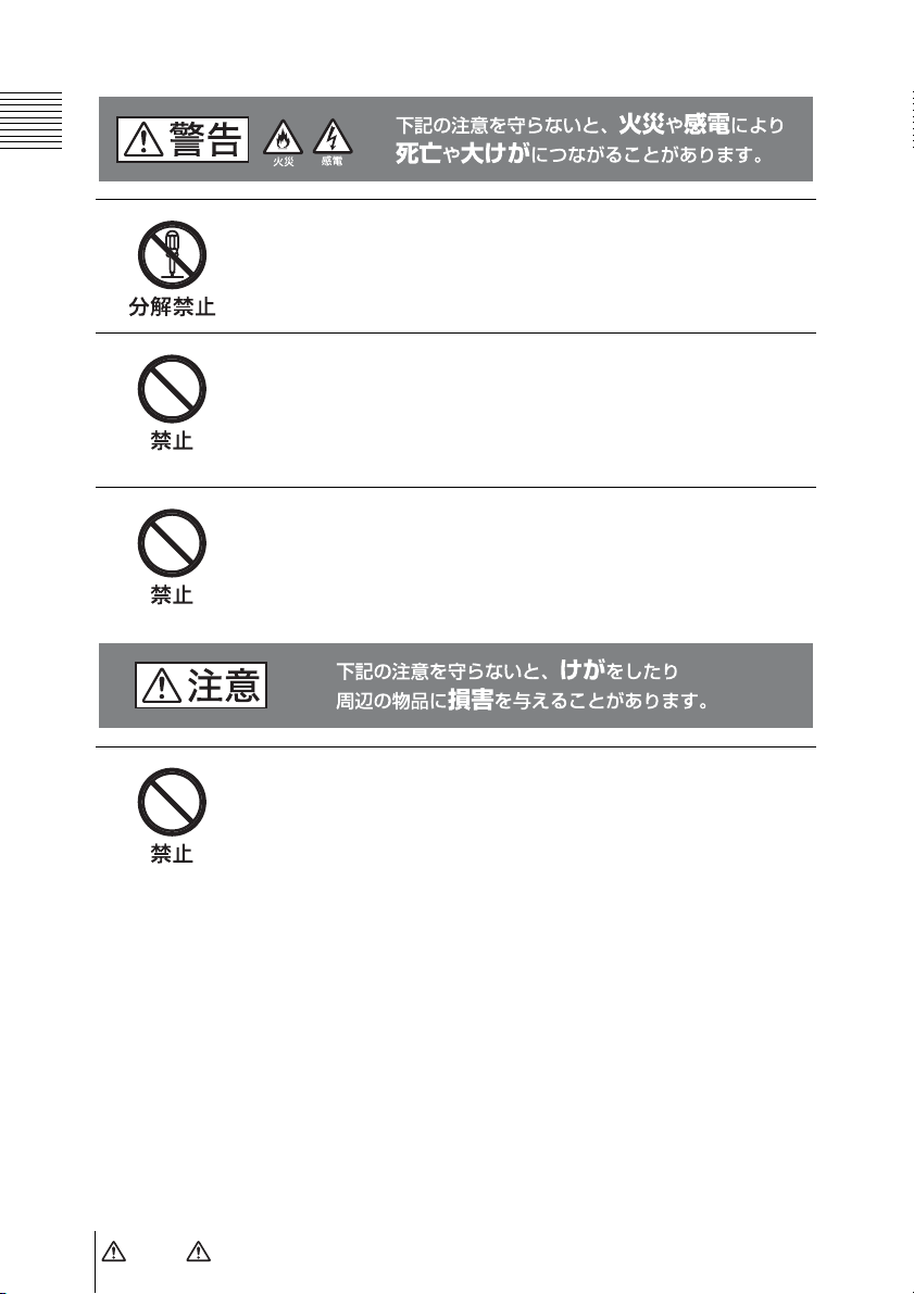
分解しない、改造しない
分解したり、改造したりすると、感電の原因となります。
ビューファインダー内部の調整や点検を行う必要がある場合は、
必ずソニーのサービス担当者にご依頼ください。
内部に水や異物を入れない
水や異物が入ると火災の原因となります。
万一、水や異物が入ったときは、すぐにカムコーダーの電源を切
り、接続コードを抜いて、ソニーのサービス担当者または営業担
当者にご相談ください。
油煙、湯気、湿気、ほこりの多い場所では設置・使用し
ない
上記のような場所で設置・使用すると、火災や感電の原因となり
ます。
ビューファインダーの接眼レンズを太陽に向けて放置し
ない
太陽光が接眼レンズを通してビューファインダー内部に焦点を結
び、火災の原因となることがあります。
4
警告・ 注意
Page 5

概要
エレクトロニックビューファインダー
DXF-20W は、2 インチワイドスクリー
ンのビューファインダーです。ソニー
PDW-F330/F350、DSR-450WS シリーズ
カムコーダーに取り付けて使用します。
DXF-20W には以下のような特長があり
ます。
16:9 ワイドスクリーン
2 インチ 16:9 ブラウン管の採用により、
16:9 表示でも映像が縮小されず見やすく
なっています。また、カムコーダー側の
設定により、画面を 4:3 に切り替えるこ
とができます。
高性能ブラウン管
• クイックスタートタイプ(電源を入れ
るのとほとんど同時に画像が現れま
す。)
• 高解像度
• 低フレア
低ひずみレンズ
アイピース部には、2 枚構成の低ひずみ
レンズを採用しているため、ひずみの少
ない映像を見ることができます。
その他
• 大口径で、目を離しても画面が見やす
くなっています。
• 別売りの防曇フィルターを取り付ける
と、呼気や水蒸気によるくもりを防ぐ
ことができます。
マーカー表示
カムコーダー側で、センターマーカーや
セーフティーゾーンマーカーなどのマー
カー表示が ON に設定されている場合、
本機のスイッチで、マーカー表示を ON/
OFF できます。
着脱可能なアイピース部
アイピース部を取り外して使うと、目を
離しても画面の中央がぼやけません。ま
た、画面やミラーにほこりが付着したと
きは、アイピース部を取り外してクリー
ニングすることができます。
概要
5
Page 6
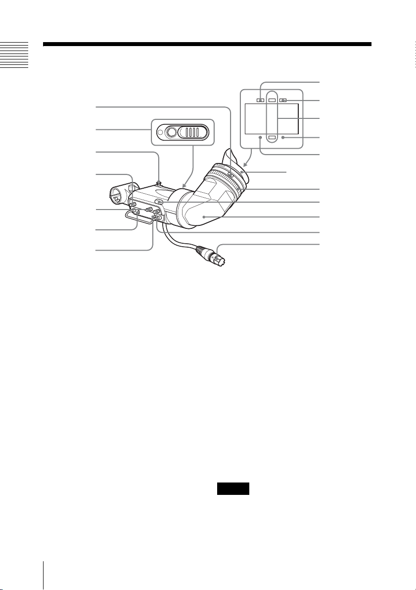
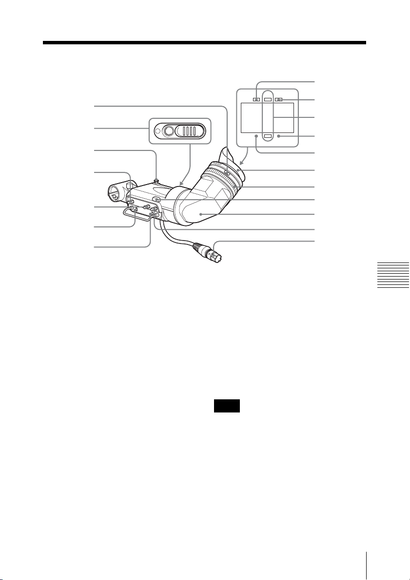
各部の名称と働き
8
1
2
3
4
5
6
7
TALLY
BATTREC
SHUTTER GAIN UP
9
0
qa
qs
アイカップ
qd
qf
qg
qh
qj
a 視度調整リング
画面の映像が最もはっきり見えるよう
に、このリングを回して視度を調整しま
す。
b カメラパーソンタリーランプ
REC/TALLY ランプ(q;)と同様に点
灯、点滅します。
このランプを使用する場合は、スライド
式のふたを開けてください。
c ストッパー
本機をカムコーダーに取付けて左右にス
ライドさせるとき、本機がカムコーダー
から外れるのを防ぎます。
d PEAKING(ピーキング)つまみ
時計方向に回すと、画面の映像の輪郭が
強調され、レンズのフォーカス合わせが
各部の名称と働き
6
容易になります。カムコーダーの出力信
号には影響しません。
e CONTRAST(コントラスト)つ
まみ
画面のコントラスト(濃淡)を調整しま
す。カムコーダーの出力信号には影響し
ません。
f DISPLAY(ディスプレイ)スイッ
チ
ビューファインダーに文字情報やセーフ
ティーゾーンなどのマーカーを表示した
いときに、ON にします。
ご注意
接続するカムコーダーによっては、あら
かじめカムコーダー側でこれらの文字情
Page 7

報やマーカーを表示する設定にしておく
必要があります。
色)を合わせてから、アイピースを抜き
取ります。
g TALLY(タリー)スイッチ
タリーランプを使用するとき、HIGH
(高輝度)または LOW(低輝度)に設定
します。REC/TALLY ランプ(q;)、カ
メラパーソンタリーランプ(2)には影
響しません。
h TALLY(タリー)ランプ(グリー
ン)
グリーンの LED ランプです。点灯、点
滅の仕様は接続するカムコーダーによっ
て異なります。
i BATT(バッテリー)ランプ(赤)
カムコーダーのバッテリーの消耗を知ら
せます。
j REC/TALLY(記録 / タリー)ラン
プ(赤)
赤色の LED ランプです。点灯、点滅の
仕様は接続するカムコーダーによって異
なります。
n タリーランプ
TALLY スイッチ(7)が HIGH(高輝
度)または LOW(低輝度)のとき、
REC/TALLY ランプ(q;)と同様に動
作します。
o 筒部
使用状況に応じて回転させることができ
ます。
ご注意
このとき、地磁気の影響で画面の位置が
ずれることがあります。
p BRIGHT(明るさ)つまみ
画面の明るさを調整します。カムコー
ダーの出力信号には影響しません。
q ビューファインダーコネクター
カムコーダーの VF 端子と接続します。
k GAINUP(ゲイン)ランプ(オレ
ンジ)
ゲインが 3dB 以上のとき点灯します。
l SHUTTER(シャッター)ランプ
(赤)
カムコーダーの SHUTTER スイッチを
ON にすると点灯します。
m ロックリング
画面を直接見たいとき、このリングを反
時計方向に回し、ロックリングと本機筒
部のそれぞれの合いマーク(オレンジ
各部の名称と働き
7
Page 8

カムコーダーに取 り付ける
ご注意
ビューファインダーを取り付けたあと、
接眼レンズを太陽に向けて放置しないで
ください。太陽光が接眼レンズを通して
ビューファインダー内部に焦点を結び、
火災の原因となることがあります。
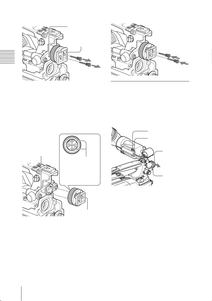
ビューファインダー シューを付け替える
カムコーダーに DXF-20W 以外のビュー
ファインダーが取り付けられている場合
は、あらかじめ取り外しておきます。
(ここでは PDW-F330 のイラストで説明
していますが、DSR-450WS の場合も同
様です。)
ご注意
VF シューコテイ
ダイ
ビューファイン
ダーシュー
2
付属のビューファインダーシューを
取り付ける。
ビューファインダーシューの裏の穴
を、VF シューコテイダイ上の2本
のピンにはめ合わせる。このとき、
ビューファインダーシューの表の△
マークが上に向くようにする。
ピン
ピンにはめ合わせる
穴(ビューファイン
ダーシューの裏)
本機は、PDW-F350 には標準であらかじ
め取り付けられているため、この作業は
不要です。
1
付属の六角レンチを使用してボルト
とスプリングワッシャーを外し、
ビューファインダーシューを VF
シューコテイダイから分離する。
カムコーダーに取り付ける
8
3
手順 1 で外したスプリングワッ
シャーとボルトで、ビューファイン
ダーシューを VF シューコテイダイ
に固定する。
f マーク
Page 9

ビューファインダーを取 り付ける
1
1 カムコーダーの左右位置固定リン
グをゆるめる。
2 本機裏側の溝をビューファイン
ダーシューにはめる。
VF 端子
ご注意
1
2
3
ケーブル
クランプ
ビュー
ファインダー
コネクター
ストッパー
溝
2
1
2
1 本機を矢印の方向にスライドさせ
て取り付け位置を決める。
2 カムコーダーの左右位置固定リン
グを締める。
3 ビューファインダーコネクターを
カムコーダーの VF 端子に差し込
み、ケーブルクランプでケーブルを
固定する。
ビュー
ファイン
ダー
シュー
左右位置
固定リン
グ
• 必ずカムコーダーの電源をOFFにして
から、ビューファインダーコネクター
をカムコーダーの VF 端子に差し込ん
でください。電源が ON の状態でコネ
クターを差し込むと、本機が正常に動
作しないことがあります。
• ビューファインダーコネクターをカム
コーダーの VF 端子の奥まで確実に差
し込んでください。コネクターが確実
に接続されていないと、画像が乱れた
り、タリーランプが正常に点灯しない
ことがあります。
取り外すときは
取り付け操作の手順を逆に実行します。
本機をカムコーダーから抜き取るとき
は、ストッパーを引き上げてください。
カムコーダーに取り付ける
9
Page 10

再び取り付けるには
アイピース部の取 り扱い
アイピース部を取り外す には
ビューファインダーから目を離して撮影
するような場合は、アイピース部を外す
と、画面全体が見やすくなります。
1
ロックリングを反時計方向いっぱい
に回して、ロックリングの合いマー
クと本機筒部の合いマーク(いずれ
もオレンジ色の線)を合わせる。
ロックリングの合いマーク
ロックリング
筒部の合いマーク
2
アイピース部を抜き取る。
1
ロックリングの合いマークと、本機
筒部の合いマークを合わせる。
2
アイピース部先端の合いマーク
(「アイピース部を取り外すには」の
手順
2 を参照)をロックリングの合
いマークに合わせて、アイピース部
を本機筒部に差し込む。
3
ロックリングを時計方向いっぱいに
回し、ロックリングの「LOCK」表
示の上の矢印を、本機筒部の合い
マークに合わせる。
画面や内部をクリーニン グするには
本機の画面や内部をクリーニングすると
きは、本機をカムコーダーから取り外
し、内部の部品を傷つけないように十分
注意して行ってください。
◆ 本機をカムコーダーから取り外す方法につい
ては、「カムコーダーに取り付ける」(8 ペー
ジ)の手順を参考にしてください。
準備
アイピース部
アイピース部先端の合いマーク
アイピース部の取り扱い
10
筒部
プロテクト
フィルター
アイカップ
ホルダー
アイカップ
パッキング
Page 11

1
本機の筒部から、アイピース部を取
り外す。
◆ 取り外しかたについては、「アイピース
部を取り外すには」(10 ページ)をご覧
ください。
2
アイカップホルダーからアイカップ
を外す。
3
アイカップホルダーから、プロテク
トフィルターをパッキングごと外
す。
4
パッキングからプロテクトフィル
ターを外す。
画面とミラーの表面のお手入れ
市販のブロアーを使ってほこりを取り除
いてください。
レンズやプロテクトフィルター
のお手入れ
市販のレンズクリーナーを使ってクリー
ニングを行なってください。
防曇フィルターを取り付けるに
は
プロテクトフィルターをパッキングから
外し、代わりに防曇フィルターをパッキ
ングにはめ込みます。
◆ プロテクトフィルターをパッキングから外す
には、「準備」(10 ページ)の手順を参考にし
てください。
ご注意
防曇フィルターをクリーニングする際
は、防曇効果を損なわないように、柔ら
かい布でからぶきしてください。
ご注意
シンナーなどの溶剤は、いっさい使わな
いでください。
防曇フィルター
撮影場所の温度条件によっては、呼気や
水蒸気によってプロテクトフィルターが
くもり、画面が見にくくなることがあり
ます。
プロテクトフィルターの代わりに、別売
りの防曇フィルターを使用すると、くも
りの発生を防ぐことができます。
アイピース部の取り扱い
11
Page 12

仕様
一般
信号形式 EIA 標準/CCIR 標準
走査 2:1 インターレース
525
2:1 インターレース
625
電源 DC12V
消費電力 3W
動作温度 −5〜+40℃
保存温度 − 20 〜+ 60 ℃
最大外形寸法 239 × 76 × 215mm
(幅/高さ/奥行
き)
質量 620g
性能
ブラウン管 白黒、2 型
水平解像度 600TV 本(画面中心
部)
パッド付きアイカップ
・ パッド部(サービスパーツ番号:
X-3678-187-1)
・ アタッチメント部(サービスパー
ツ番号:3-682-494-02)
関連製品
プロフェッショナルディスクカムコー
ダー PDW-F330/F350
デジタルカムコーダー DSR-450WS
1) 本機は、PDW-F350 には標準で付属していま
す。
仕様および外観は、改良のため予告なく
変更することがありますが、ご了承くだ
さい。
お使いになる前に、必ず動作確認を
行ってください。故障その他に伴う営
業上の機会損失等は保証期間中および
保証期間経過後にかかわらず、補償は
いたしかねますのでご了承ください。
1)
付属品
取扱説明書 (1)
六角レンチ (1)
VF(ビューファインダー)シュー
ASSY(A-8278-412-H)(1)
保証書 (1)
別売り品
防曇フィルター
(サービスパーツ番号:1-547-341-11)
老視用レンズ(視度− 2.8D 〜+ 2.0D)
(サービスパーツ番号:
A-8262-537-A)
低倍率レンズ(視度− 3.6D 〜− 0.8D)
(サービスパーツ番号:
A-8262-538-A)
仕様
12
Page 13

English
WARNING
To reduce the risk of fire or electric
shock, do not expose this apparatus
to rain or moisture.
To avoid electrical shock, do not
open the cabinet. Refer servicing to
qualified personnel only.
For the customers in the U.S.A.
This equipment has been tested and found
to comply with the limits for a Class B
digital device, pursuant to Part 15 of the
FCC Rules. These limits are designed to
provide reasonable protection against
harmful interference in a residential
installation. This equipment generates,
uses, and can radiate radio frequency
energy and, if not installed and used in
accordance with the instructions, may cause
harmful interference to radio
communications. However, there is no
guarantee that interference will not occur in
a particular installation. If this equipment
does cause harmful interference to radio or
television reception, which can be
determined by turning the equipment off
and on, the user is encouraged to try to
correct the interference by one or more of
the following measures:
For the customers in Europe
This product with the CE marking complies
with the EMC Directive issued by the
Commission of the European Community.
Compliance with this directive implies
conformity to the following European
standards:
• EN55103-1 :Electromagnetic
Interference (Emission)
• EN55103-2 : Electromagnetic
Susceptibility (Immunity)
This product is intended for use in the
following Electromagnetic
Environment(s): E1 (residential), E2
(commercial and light industrial), E3
(urban outdoors), E4 (controlled EMC
environment, ex. TV studio).
For the customers in Europe
The manufacturer of this product is Sony
Corporation, 1-7-1 Konan, Minato-ku,
Tokyo, Japan.
The Authorized Representative for EMC
and product safety is Sony Deutschland
GmbH, Hedelfinger Strasse 61, 70327
Stuttgart, Germany. For any service or
guarantee matters please refer to the
addresses given in separate service or
guarantee documents.
GB
– Reorient or relocate the receiving
antenna.
– Increase the separation between the
equipment and receiver.
– Connect the equipment into an outlet on
a circuit different from that to which the
receiver is connected.
– Consult the dealer or an experienced
radio/TV technician for help.
You are cautioned that any changes or
modifications not expressly approved in
this manual could void your authority to
operate this equipment.
13
Page 14

Table of Contents
Outline ...................................................................................15
Location and Function of Parts........................................... 16
Attaching the Viewfinder to a Camcorder .........................17
Replacing the Viewfinder Shoe ......................................17
Attaching the Viewfinder ...............................................18
Detaching the Viewfinder ...............................................19
Handling the Eyepiece ..........................................................19
Detaching the Eyepiece ..................................................19
Cleaning the Screen or Interior .......................................20
Fog-Proof Filter ..............................................................20
Specifications .........................................................................21
14
Table of Contents
Page 15

Outline
The DXF-20W is a wide-aspect 2-inch
screen (aspect ratio 16:9) viewfinder. It can
be attached to a Sony PDW-F330/F350 or
DSR-450WS/450WSP-series camcorder.
The DXF-20W has the features described
below.
16:9 Wide Screen
The 2-inch 16:9 CRT provides a clear, fullsize 16:9 aspect ratio image. You can
switch to a 4:3 aspect ratio image with a
setting on the camcorder.
High-Performance CRT
• Quick-start type (The image appears as
soon as the camcorder is turned on.)
• Enhanced resolution
• Reduced flare
Others
• Due to its large diameter, you can see the
screen well at a longer distance.
• Fitting a fog-proof filter (not supplied)
over the viewfinder lens prevents breath
or vapor condensation on the lens.
Marker Indication
When the camcorder is set so that markers
such as a center marker or safety zone
marker are indicated on the viewfinder
screen, marker indication on/off switching
can be controlled on the viewfinder.
Removable Eyepiece
Detaching the eyepiece gives you a clear
view of the center of the screen even with
your eye away from the viewfinder. You
can clean dust from the screen or the mirror
by detaching the eyepiece.
Low Distortion Lens
The eyepiece includes a two-element lowdistortion lens, enabling you to view a lowdistortion image.
Outline
15
Page 16

Location and Function of Parts
8
TALLY
BATTREC
1
2
SHUTTER GAIN UP
3
4
5
6
7
9
0
qa
qs
Eyecup
qd
qf
qg
qh
qj
a Eyepiece focusing ring
Turn this ring to adjust viewfinder image
into sharp focus.
b Camera person tally light
This lights or flashes in the same way as the
REC/TALLY indicators (q;).
To use this light, open the sliding lid.
c Stopper
When the viewfinder is attached to the
camcorder and slid sideways, this prevents
the viewfinder from becoming detached
from the camcorder.
d PEAKING control
Turn this clockwise to emphasize outlines
on the screen, to make lens focusing easier.
This has no effect on the signal output from
the camcorder.
e CONTRAST control
Adjusts the screen contrast. This has no
effect on the signal output from the
camcorder.
Location and Function of Parts
16
f DISPLAY switch
Set this to ON to display text and markers
such as safety zone on the viewfinder
screen.
Note
Depending on the camcorder connected, it
is first necessary to set the text or markers to
be shown with a camcorder setting.
g TALLY switch
When the tally light is used, set to HIGH
(high intensity) or LOW (low intensity).
This does not affect the REC/TALLY
indicators (q;) or camera person tally light
(2).
h TALLY indicator (green)
The way in which this green LED indicator
lights or flashes depends on the
specification of the connected camcorder.
Page 17

i BATT indicator (red)
Indicates that the camcorder battery is
exhausted.
j REC/TALLY indicators (red)
The way in which this red LED indicator
lights or flashes depends on the
specification of the connected camcorder.
Attaching the Viewfinder to a Camcorder
k GAIN UP indicator (orange)
Lights when the gain is 3 dB or more.
l SHUTTER indicator (red)
Lights when the camcorder SHUTTER
switch is in the ON position.
m Lock ring
To directly view the screen, turn this ring
counterclockwise, to align the orange
marks on the lock ring and the barrel of the
viewfinder, and remove the eyepiece.
n Tally light
When the TALLY switch (7) is in the
HIGH (high intensity) or LOW (low
intensity) position, this operates in the same
way as the REC/TALLY indicators (q;).
o Barrel
You can rotate this for convenience.
Note
The position of the image may change, as a
result of the earth's magnetic field.
p BRIGHT control
Adjusts the screen brightness. This has no
effect on the signal output from the
camcorder.
Note
When the viewfinder is attached, do not
leave the camera (or the camcorder) with
the eyepiece facing the sun. Direct sunlight
can enter through the eyepiece, be focused
in the viewfinder and cause fire.
Replacing the Viewfinder Shoe
When the camcorder has been used with a
viewfinder other than the DXF-20W, it is
first necessary to replace the shoe.
(The following illustrations show the PDWF330, but the same applies to the DSR450WS/450WSP.)
Note
If you are using the PDW-F350 camcorder,
this operation is not required. The
camcorder was shipped from the factory
with the DXF-20W attached to it.
1 With the supplied hexagonal wrench,
remove the bolts and spring washers,
and detach the viewfinder shoe from
theVF shoe fixing bracket.
q Viewfinder connector
Connect to the VF connector of the
camcorder.
Attaching the Viewfinder to a Camcorder
17
Page 18
VF shoe fixing
bracket
Viewfinder shoe
2 Attach the supplied viewfinder shoe.
Align the holes in the backside of the
viewfinder shoe with the two pins on
the VF shoe fixing bracket. At this
point, the triangular mark on the
viewfinder shoe should be facing
upward.
Pins
Holes to align with
the pins (backside
of the viewfinder
shoe)
Triangular mark
3 With the spring washers and bolts
removed in step 1, fasten the
viewfinder shoe to the VF shoe fixing
bracket.
Attaching the Viewfinder
1 1 Loosen the left-right positioning
ring of the camcorder.
2 Engage the slide rail on the
viewfinder backside with the
viewfinder shoe.
Stopper
Slide rail
2
1
View finder
shoe
Left-light
positioning
ring
2 1 Slide the viewfinder in the
direction shown by the arrow to the
required mounting position.
2 Tighten the left-right positioning
ring of the camcorder.
3 Plug the viewfinder connector into
the VF connector of the camcorder,
and clip the cable into the cable clamp .
Attaching the Viewfinder to a Camcorder
18
Page 19

Handling the
1
2
3
Cable clamp
Viewfinder
connector
VF connector
Notes
• Be sure to power off the camorder before
plugging the viewfinder connector into
the VF connector on the camorder. If the
connector is plugged in while the power
is on, the viewfinder may not operate
correctly.
• Make sure that the viewfinder connector
is pushed fully into the VF connector on
the camorder. If the connector is not
firmly connected, the image may break
up, or the tally light may not operate
properly.
Eyepiece
Detaching the Eyepiece
Detaching the eyepiece gives you a clear
view of the screen even with your eye away
from the viewfinder.
1 Turn the eyepiece lock ring fully
counterclockwise to line up the orange
match mark on the lock ring with the
orange match mark on the viewfinder
barrel.
Lock ring match mark
Lock ring
Match mark on the viewfinder barrel
2 Detach the eyepiece.
Detaching the Viewfinder
To detach the viewfinder from the
camcorder, conduct the attachment
procedure in reverse. When removing the
viewfinder from the camcorder, pull up the
stopper.
Match mark on end of eyepiece
Handling the Eyepiece
19
Page 20

Refitting the Eyepiece
1 Align the match mark on the eyepiece
lock ring with that on the viewfinder
barrel.
2 Align the match mark on the end of the
eyepiece (see Step 2 in “Detaching the
Eyepiece”) with that of the eyepiece
lock ring, then insert the eyepiece into
the viewfinder barrel.
3 Turn the eyepiece lock ring clockwise
until its “LOCK” indication arrow
points to the match mark on the
viewfinder barrel.
Cleaning the Screen or Interior
When cleaning the screen or the interior of
the viewfinder, detach the viewfinder from
the camcorder, then clean it taking care not
to damage the components.
To detach the viewfinder from the camcorder, see
“Attaching the Viewfin der to a Camcorder” on page
17 and conduct the attachment procedure in reverse.
Preparation for Cleaning
Eyepiece
For the detaching procedure, see “Detaching
the Eyepiece” on page 19.
2 Remove the eyecup from the eyecup
holder.
3 Remove the protecting filter, together
with the packing ring, from the eyecup
holder.
4 Detach the protecting filter from the
packing ring.
To clean the screen or the mirror
Use a commercially available dust blower.
To clean the lens or the protecting
filter
Use a commercially available lens cleaner.
Note
Do not use organic solvents such as
thinners.
Fog-Proof Filter
Depending on the temperature and
humidity, the protecting filter may mist,
especially if you breathe near it. You can
replace the protecting filter with an optional
fog-proof filter to prevent the fogging.
Attaching the fog-proof filter
Detach the protecting filter from the
packing ring, and replace it with the fogproof filter.
Viewfinder
barrel
Eyecup
holder
Protecting
filter
1 Detach the eyepiece from the
viewfinder barrel.
Handling the Eyepiece
20
Eyecup
Packing ring
To remove the packing from th e protecting filter, see
the procedure “Preparation for Cleaning” (page
20).
Note
When cleaning the fog-proof filter, wipe the
filter very gently with a soft cloth to avoid
impairing the anti-fogging effect.
Page 21

Specifications
Cushioned eyecup
• Pad (Service Part No. X-3678-187-1)
• Attachment (Service Part No.
3-682-494-02)
General
Signal format
EIA compliant / CCIR compliant
Scan 2:1 Interlaced 525
2:1 Interlaced 625
Power requirements
12 V DC
Power consumption
3 W
Operating temperature
–5°C to +40°C (23°F to +104°F)
Storage temperature
–20°C to +60°C (–4°F to +140°F)
External dimensions
239 × 76 × 215 mm (9
inches) (w/h/d)
Mass 620 g (1 lb 5 oz)
Performance
CRT 2-inch monochrome
Horizontal resolution
600 TV lines (at center)
Accessories
Operating Instructions (1)
Hexagonal wrench (1)
SHOE ASSY (Service Part No.
A-8278-412-H) (1)
Warranty Booklet (1)
1
/2 × 3 × 81/2
Related Products
Professional Disc Camcorder
PDW-F330/F350
Digital Camcorder DSR-450WS/450WSP
1) This unit is supplied as standard equipment
with the PDW-F350.
Design and specifications are subject to
change without notice.
Note
Always verify that the unit is operating
properly before use. SONY WILL NOT
BE LIABLE FOR DAMAGES OF ANY
KIND INCLUDING, BUT NOT
LIMITED TO, COMPENSATION OR
REIMBURSEMENT ON ACCOUNT OF
THE LOSS OF PRESENT OR
PROSPECTIVE PROFITS DUE TO
FAILURE OF THIS UNIT, EITHER
DURING THE WARRANTY PERIOD
OR AFTER EXPIRATION OF THE
WARRANTY, OR FOR ANY OTHER
REASON WHATSOEVER.
1)
Accessories Not Supplied
Fog-proof filter (Service Part No.
1-547-341-11)
Lens assembly (farsighted) (–2.8 D
to +2.0 D) (Service Part No.
A-8262-537-A)
Lens assembly (low magnification) (–3.6 D
to –0.8 D) (Service Part No.
A-8262-538-A)
Specifications
21
Page 22

Français
AVERTISSEMENT
Afin de réduire les risques
d’incendie ou d’électrocution, ne pas
exposer cet appareil à la pluie ou à
l’humidité.
Afin d’écarter tout risque
d’électrocution, garder le coffret
fermé. Ne confier l’entretien de
l’appareil qu’à un personnel qualifié.
Pour les clients européens
Ce produit portant la marque CE est
conforme à la Directive sur la compatibilité
électromagnétique (EMC) émise par la
Commission de la Communauté
européenne.
La conformité à cette directive implique la
conformité aux normes européennes
suivantes :
• EN55103-1 : Interférences
électromagnétiques (émission)
• EN55103-2 : Sensibilité
électromagnétique (immunité)
Ce produit est prévu pour être utilisé dans
les environnements électromagnétiques
suivants :
E1 (résidentiel), E2 (commercial et
industrie légère), E3 (urbain extérieur) et
E4 (environnement EMC contrôlé, ex.
studio de télévision).
Pour les clients en Europe
Le fabricant de ce produit est Sony
Corporation, 1-7-1 Konan, Minato-ku,
Tokyo, Japon.
Le représentant autorisé pour EMC et la
sécurité des produits est Sony Deutschland
GmbH, Hedelfinger Strasse 61, 70327
Stuttgart, Allemagne. Pour toute question
concernant le service ou la garantie,
veuillez consulter les adresses indiquées
dans les documents de service ou de
garantie séparés.
22
Page 23

Table des matières
Configuration ........................................................................24
Localisation et fonction des pièces et des commandes....... 25
Mise en place du viseur sur un caméscope .........................27
Remplacement de la griffe du viseur ..............................27
Fixation du viseur ...........................................................28
Retrait du viseur ..............................................................28
Manipulation de l’oculaire ...................................................29
Retrait de l’oculaire ........................................................29
Nettoyage de l’ecran ou de l’intérieur ............................29
Opérations préalables au nettoyage ................................30
Filtre anti buée ................................................................30
Spécifications .........................................................................31
FR
Table des matières
23
Page 24

Configuration
Le DXF-20W est un écran de viseur 2
pouces de grand format (rapport d’aspect
16:9). Il peut être adapté sur les
caméscopes Sony de série PDW-F330/
F350 ou DSR-450WS/450WSP.
Le DXF-20W présente les caractéristiques
décrites ci-dessous.
Ecran large 16:9
Le CRT 2 pouces 16:9 fournit une image
claire plein écran avec un rapport d’aspect
de 16:9. Vous pouvez passer à une image de
rapport d’aspect de 4:3 avec un réglage du
caméscope.
CRT haute-performance
• A démarrage rapide (L’image apparaît
dès que le camécope est allumé.)
• Résolution améliorée
• Lumière parasite réduite
Oculaire amovible
Le retrait de l’oculaire vous offre une vue
claire du centre de l’écran même lorsque
votre oeil est éloigné du viseur. Vous
pouvez nettoyer la poussière de l’écran ou
du miroir en retirant l’oculaire.
Objectif à faible distorsion
L’oculaire comprend un objectif à faible
distorsion de deux éléments, vous
permettant de voir une image peu déformée.
Autres
• En raison de son diamètre important,
vous pouvez avoir une bonne vision de
l’écran à une distance plus grande.
• La mise en place d’un filtre anti buée
(non fournie) sur l’objectif du viseur
évite la formation de condensation due à
la vapeur ou à la respiration sur l’objectif.
Indication de repère
Lorsque le caméscope est réglé de telle
façon que des repères comme un repère
central ou un repère de zone de sécurité sont
indiqués sur l'écran du viseur, la
commutation on/off de l'indication de
repère peut être contrôlée sur le viseur.
Configuration
24
Page 25

Localisation et fonction des pièces et
8
des commandes
TALLY
BATTREC
1
2
SHUTTER GAIN UP
3
4
5
6
7
9
0
qa
qs
Oeillère
qd
qf
qg
qh
qj
a Bague de mise au point de l’oculaire
Tournez cette bague pour régler l’image du
viseur avec une mise au point précise.
b Eclairage tally de personne de
caméra
Il s’allume ou clignote de la même façon
que les indicateurs REC/TALLY (q;).
Pour utiliser cet éclairage, ouvrez le
couvercle coulissant.
c Butée
Le fait de fixer le viseur au caméscope et à
la glissière de côté évite qu’il soit détaché
du caméscope.
d Commande PEAKING
Tournez ceci dans le sens des aiguilles
d’une montre pour mettre en évidence les
contours sur l’écran afin de rendre plus
aisée la mise au point de l’objectif. Cela n’a
aucun effet sur la sortie de signal du
caméscope.
Localisation et fonction des pièces et des commandes
e Commande CONTRAST
Règle le contraste de l’écran. Cela n’a
aucun effet sur la sortie de signal du
caméscope.
f Commutateur DISPLAY
Placez-le sur ON pour afficher le texte et les
repères comme zone de sécurité sur l'écran
du viseur.
Remarque
En fonction du caméscope connecté, il faut
d'abord définir le texte ou les repères à
afficher avec un réglage du caméscope.
g Commutateur TALLY
Lorsque vous utilisez l’éclairage tally,
placez-le sur HIGH (haute intensité) ou
LOW (basse intensité).
Ceci n’affecte pas les indicateurs REC/
TALLY (q;) ou l’éclairage tally de
personne de caméra (2).
25
Page 26

h Indicateur TALLY (vert)
La façon de s’allumer ou de clignoter du
LED vert dépend des spécifications du
caméscope connecté.
p Commande BRIGHT
Règle la luminosité de l’écran. Cela n’a
aucun effet sur la sortie de signal du
caméscope.
i Indicateur BATT (rouge)
Il indique que la batterie du caméscope est
épuisée.
j Indicateurs REC/TALLY (rouges)
La façon de s’allumer ou de clignoter du
LED rouge dépend des spécifications du
caméscope connecté.
k Indicateur GAIN UP (orange)
Il s’allume lorsque le gain est de 3 dB au
minimum.
l Indicateur SHUTTER (rouge)
Il s’allume quand le commutateur
SHUTTER du caméscope est en position
ON.
m Bague de verrouillage
Pour voir directement l’écran, tournez cette
bague dans le sens inverse des aiguilles
d’une montre afin d’aligner les repères
orange sur la bague de verrouillage et le
barillet du viseur, puis retirez l’oculaire.
n Eclairage tally
Lorsque le commutateur TALLY (7) est
en position HIGH (haute intensité) ou LOW
(basse intensité), il fonctionne comme les
indicateurs REC/TALLY (q;).
q Connecteur de viseur
Raccordez au connecteur VF du
caméscope.
o Barillet
Vous pouvez le faire pivoter pour plus de
commodité.
Remarque
La position de l’image peut changer à cause
du champ magnétique terrestre.
Localisation et fonction des pièces et des commandes
26
Page 27

Mise en place du
Bague de fixation
de la griffe VF
viseur sur un
caméscope
Remarque
Lorsque le viseur est fixé, ne laissez pas
l’appareil photo (ou le caméscope) avec
l’oculaire face au soleil. Les rayons du
soleil risqueraient de passer directement à
travers l’oculaire, d’être concentrés par le
viseur et de causer un incendie.
Remplacement de la griffe du viseur
Lorsque le caméscope a été utilisé avec un
autre viseur que le DXF-20W, il est tout
d’abord nécessaire de remplacer la griffe.
(Les illustrations suivantes présentent le
PDW-F330, mais elles s’appliquent
également au DSR-450WS/450WSP.)
Remarque
Si vous utilisez le caméscope PDW-F350,
cette opération n’est pas nécessaire. Le
caméscope est sorti d'usine avec le DXF20W.
1 A l'aide de la clé hexagonale fournie,
retirez les boulons et les rondelles
ressort et retirez la griffe du viseur de
la bague de fixation de la griffe VF.
Griffe du viseur
2 Fixation de la griffe fournie du viseur.
Alignez des trous de la face arrière de
la griffe du viseur avec les deux
broches de la bague de fixation de la
griffe VF. A ce moment, le repère
triangulaire sur la griffe du viseur
devrait être orienté vers le haut.
Broches
Trous à aligner avec
les broches (face
arrière de la griffe du
viseur)
Repère
triangulaire
3 Une fois les boulons et les rondelles
ressort retirés à l'étape 1, attachez la
griffe du viseur à la bague de fixation
de la griffe VF.
Mise en place du viseur sur un caméscope
27
Page 28

2
1
3
Fixation du viseur
1 1 Desserrez la bague de
positionnement gauche/droite du
caméscope.
2 Insérez le rail coulissant de la face
arrière du viseur de la griffe du viseur.
Butée
Rail coulissant
2
1
Griffe du
viseur
Bague de
positionnement
gauche/
2 1 Faites coulisser le viseur dans la
direction indiquée par la flèche pour
arriver à la position de montage
requise.
2 Serrez la bague de positionnement
gauche/droite du caméscope.
3 Raccordez le connecteur du viseur
au connecteur VF du caméscope et
insérez le câble dans l’attache de câble.
Attache de câble
Connecteur
de viseur
Connecteur VF
Remarques
• Assurez-vous d’éteindre le caméscope
avant de raccorder le connecteur du
viseur au connecteur VF du caméscope.
Si le connecteur est raccordé alors que
l’unité n’est pas éteinte, le viseur peut ne
pas fonctionner correctement.
• Assurez-vous que le connecteur du viseur
est complètement enfoncé dans le
connecteur VF du caméscope. Si le
connecteur n’est pas raccordé
fermement, l’image peut être altérée ou
l’éclairage tally peut ne pas fonctionner
correctement.
Retrait du viseur
Pour retirer le viseur du caméscope, suivez
la procédure de mise en place en sens
inverse. Lorsque vous retirez le viseur du
caméscope, tirez la butée vers le haut.
Mise en place du viseur sur un caméscope
28
Page 29

Manipulation de l’oculaire
Retrait de l’oculaire
Le retrait de l’oculaire vous offre une vue
claire de l’écran même lorsque votre oeil est
éloigné du viseur.
1 Tournez la bague de verrouillage de
l’oculaire complètement dans le sens
inverse des aiguilles d’une montre
pour aligner le repère d’alignement
orange de la bague de verrouillage
avec le repère d’alignement orange sur
le barillet du viseur.
Repère d’alignement de la bague de
verrouillage
Bague de verrouillage
Repère d’alignement sur le barillet du
viseur
2 Retirez l’oculaire.
Repère d’alignement sur l’extrémité de
l’oculaire
Réinstallation de l’oculaire
1 Alignez le repère d’alignement de la
bague de verrouillage de l’oculaire
avec celui du barillet du viseur.
2 Aligner le repère d’alignement sur
l’extrémité de l’oculaire (voir l’etape 2
dans « Retrait de l’Oculaire ») avec
celui de la bague de verrouillage de
l’oculaire, puis insérez l’oculaire dans
le barillet du viseur.
3 Tournez la bague de verrouillage de
l’oculaire dans le sens des aiguilles
d’une montre jusqu’à ce que sa flèche
d’indication « LOCK » soit alignée
avec le repère d’alignement du barillet
du viseur.
Nettoyage de l’ecran ou de l’intérieur
Pour nettoyer l’écran ou l’intérieur du
viseur, retirez le viseur du caméscope puis
nettoyez-le en faisant attention à ne pas en
endommager les composants.
Pour retirer le viseur du caméscope, voir « Mise en
place du viseur sur un caméscope » à la page 27 et
suivre la procédure de mise en place en sens inverse.
Manipulation de l’oculaire
29
Page 30

Opérations préalables au nettoyage
Oculaire
Barillet du
viseur
Support
d’oeillère
Filtre de
protection
Oeillère
Bague
d’étanchéité
Filtre anti buée
Le filtre de protection peut s’embuer, selon
la température et l’humidité, notamment si
vous respirez à côté. Vous pouvez
remplacer le filtre de protection par un filtre
anti buée en option pour éliminer la
condensation.
Mise en place du filtre anti buée
Retirez le filtre de protection de la bague
d’étanchéité et replacez-le avec le filtre anti
buée.
Pour retirer l’emballage du filtre de protection, voir
la procédure dans la section « Opérations
préalables au nettoyage » (page 30).
1 Retirez l’oculaire du barillet du viseur.
Pour la procédure de retrait, voir « Retrait de
l’oculaire » à la page 29.
2 Retirez l’oeillère du support d’oeillère.
3 Retirez le filtre de protection et la
bague d’étanchéité du support
d’oeillère.
4 Retirez le filtre de protection de la
bague d’étanchéité.
Pour nettoyer l’écran du miroir
Utilisez un ventilateur à poussière
disponible dans le commerce.
Pour nettoyer l’objectif ou le filtre
de protection
Utilisez un produit de nettoyage d’objectif
disponible dans le commerce.
Remarque
N’utilisez jamais de solvants organiques
tels que des diluants.
Remarque
Lors du nettoyage du filtre anti buée,
essuyez le filtre très doucement avec un
chiffon doux afin d’éviter de déteriorer
l’effet anti buée.
Manipulation de l’oculaire
30
Page 31

Spécifications
Caractéristiques générales
Format de signal
Compatible EIA / Compatible
CCIR
Balayage
2:1 Entrelacé 525
2:1 Entrelacé 625
Configuration d’énergie requise.
12V CC
Consommation d’énergie
3 W
Température de fonctionnement
–5°C à +40°C (23°F à +104°F)
Température de stockage
–20°C à +60°C (–4°F à +140°F)
Dimensions externes
239 × 76 × 215 mm
1
/2 × 3 × 81/2 pouces) (l/h/p)
(9
Poids 620g
Performance
CRT monochrome 2 pouces
Résolution horizontale
600 lignes TV (au centre)
Accessoires
Mode d’emploi (1)
Clé hexagonale (1)
SHOE ASSY
(Référence nº A-8278-412-H) (1)
Certificat de garantie (1)
Assemblage de l’objectif (faible
grossissement) (–3,6 D à –0,8 D)
(Référence nº A-8262-538-A)
Oeillère matelassée
• Protection (Référence nº X-3678-187-1)
• Fixation (Référence nº 3-682-494-02)
Produits apparentés
Professional Disc Camcorder
PDW-F330/F350
Digital Camcorder DSR-450WS/450WSP
1) Cette unité est fournie en standard avec le
PDW-F350.
La conception et les spécifications sont
sujettes à modification sans préavis.
Remarque
Vérifiez toujours que l’appareil
fonctionne correctement avant
l’utilisation. Sony n’assumera pas de
responsabilité pour les dommages de
quelque sorte qu’ils soient, incluant
mais ne se limitant pas à la
compensation ou au remboursement, à
cause de la perte de profits actuels ou
futurs suite à la défaillance de cet
appareil, que ce soit pendant la période
de garantie ou après son expiration, ou
pour toute autre raison quelle qu’elle
soit.
1)
Accessoires non fournis
Filtre anti buée
(Référence nº 1-547-341-11)
Assemblage de l’objectif (hypermétrope)
(–2,8 D à +2,0 D)
(Référence nº A-8262-537-A)
Spécifications
31
Page 32

Deutsch
WARNUNG
Um die Gefahr von Bränden oder
elektrischen Schlägen zu verringern,
darf dieses Gerät nicht Regen oder
Feuchtigkeit ausgesetzt werden.
Um einen elektrischen Schlag zu
vermeiden, darf das Gehäuse nicht
geöffnet werden. Überlassen Sie
Wartungsarbeiten stets nur
qualifiziertem Fachpersonal.
Für Kunden in Europa
Dieses Produkt besitzt die CEKennzeichnung und erfüllt die EMVRichtlinie der EG-Kommission.
Angewandte Normen:
• EN55103-1: Elektromagnetische
Verträglichkeit (Störaussendung)
• EN55103-2: Elektromagnetische
Verträglichkeit (Störfestigkeit),
für die folgenden elektromagnetischen
Umgebungen: E1 (Wohnbereich), E2
(kommerzieller und in beschränktem Maße
industrieller Bereich), E3 (Stadtbereich im
Freien) und E4 (kontrollierter
EMVBereich, z.B. Fernsehstudio).
Für Kunden in Europa
Der Hersteller dieses Produkts ist Sony
Corporation, 1-7-1 Konan, Minato-ku,
Tokyo, Japan.
Der autorisierte Repräsentant für EMV und
Produktsicherheit ist Sony Deutschland
GmbH, Hedelfinger Strasse 61, 70327
Stuttgart, Deutschland. Bei jeglichen
Angelegenheiten in Bezug auf
Kundendienst oder Garantie wenden Sie
sich bitte an die in den separaten
Kundendienst- oder Garantiedokumenten
aufgeführten Anschriften.
32
Page 33

Inhalt
Überblick ...............................................................................34
Position und Funktion der Teile.......................................... 35
Montage des Suchers an einem Camcorder .......................37
Austausch des Sucherschuhs ..........................................37
Montage des Suchers ......................................................38
Abnehmen des Suchers ...................................................38
Umgang mit dem Okular .....................................................39
Abnehmen des Okulars ...................................................39
Reinigung des Bildschirms oder des Innenbereichs .......39
Kondensation verhindernder Filter .................................40
Technische Daten ..................................................................41
DE
Inhalt
33
Page 34

Überblick
Der DXF-20W ist ein Breitformatsucher
mit 2-Zoll-Bildschirm (Bildformat 16:9).
Er kann an einen Camcorder der
Sonyproduktreihe PDW-F330/F350 oder
DSR-450WS/450WSP angeschlossen
werden.
Der DXF-20W hat die unten beschriebenen
Eigenschaften.
16:9 Breitformat
Der 2-Zoll 16:9 CRT sorgt für ein
deutliches Bild in voller Größe im
Bildformat 16:9. Sie können mit einer
Einstellung auf dem Camcorder zu einem
4:3 Bildformat wechseln.
Hochleistungs-CRT
• Schnellstart (Das Bild erscheint, sobald
der Camcorder eingeschaltet wird.)
• Höhere Auflösung
• Verringertes Streulicht
Objektiv mit geringer
Verzerrung
Das Okular enthält ein aus zwei Elementen
bestehendes Objektiv mit geringer
Verzerrung, das ein verzerrungsarmes Bild
liefert.
Sonstiges
• Aufgrund seines großen Durchmessers
ist der Bildschirm auch aus größerer
Entfernung gut zu erkennen.
• Durch Anbringen eines Kondensation
verhindernden Filters (nicht im
Lieferumfang enthalten) am
Sucherobjektiv, wird Kondensation von
Atem oder Dampf auf dem Objektiv
vermieden.
Markierungsanzeige
Wenn der Camcorder so eingestellt wurde,
dass Markierungen wie eine
Mittelmarkierung oder eine
Sicherheitszonenmarkierung in der
Sucheranzeige erscheint, kann die
Markierungsanzeige am Sucher ein- bzw.
ausgeschaltet werden.
Abnehmbares Okular
Wenn Sie das Okular abnehmen, haben Sie
eine klare Sicht auf die Bildschirmmitte,
sogar wenn Sie Ihr Auge nicht direkt an den
Sucher halten. Wenn Sie das Okular
abnehmen, können Sie Staub vom
Bildschirm oder vom Spiegel entfernen.
Überblick
34
Page 35

Position und Funktion der Teile
8
TALLY
BATTREC
1
2
SHUTTER GAIN UP
3
4
5
6
7
9
0
qa
qs
qd
qf
qg
qh
qj
Augenschälchen
a Okularfokussierring
Drehen Sie zur Scharfstellung des
Sucherbilds an diesem Ring.
b Kontrollanzeige Kameramann/-frau
Diese Anzeige leuchtet oder blinkt genau
wie die Anzeigen REC/TALLY (q;).
Wenn Sie diese Anzeige verwenden
möchten, öffnen Sie die Schiebeabdeckung.
c Anschlag
Wenn der Sucher an dem Camcorder
befestigt und zur Seite geschoben ist, kann
er sich nicht ungewollt lösen.
d Regler PEAKING
Drehen Sie diesen zum Hervorheben von
Konturen im Uhrzeigersinn, um das
Scharfstellen des Objektivs zu
vereinfachen. Dies hat keinen Einfluss auf
die Ausgabe des Signals vom Camcorder.
e Regler CONTRAST
Regelt den Bildschirmkontrast. Dies hat
keinen Einfluss auf die Ausgabe des Signals
vom Camcorder.
f DISPLAY Schalter
Auf ON stellen, um Textinformationen und
Markierungen wie die Sicherheitszone auf
der Sucheranzeige wiederzugeben.
Hinweis
Abhängig von dem angeschlossenen
Camcorder ist es notwendig erst den Text
oder die Markierungen einzustellen, die in
der Camcordereinstellung gezeigt werden
sollen.
Position und Funktion der Teile
35
Page 36

g TALLY Schalter
Zur Verwendung der Kontrollanzeige
HIGH (sehr lichtintensives Motiv) oder
LOW (wenig lichtintensives Motiv)
einstellen.
Dies hat jedoch keinen Einfluss auf die
REC/TALLY Anzeigen (q;) oder die
Kontrollanzeige des Kamerabetreibers
(2).
n Kontrollanzeige
Wenn der Schalter TALLY (7) auf HIGH
(sehr lichtintensives Motiv) oder LOW
(wenig lichtintensives Motiv) steht, hat
diese Anzeige dieselbe Funktion wie die
Anzeigen REC/TALLY (q;).
o Zylinder
Sie können diesen nach Belieben drehen.
h Anzeige TALLY (Kontrollanzeige)
(grün)
Die Art und Weise, in der diese grüne LED
Anzeige leuchtet oder blinkt, ist von den
Spezifikationen der angeschlossenen des
Camcorders abhängig.
i Anzeige BATT (rot)
Zeigt an, dass die Batterie des Camcorders
leer ist.
j REC/TALLY Anzeigen (rot)
Die Art und Weise in der diese rote LED
Anzeige leuchtet oder blinkt, ist von den
Spezifikationen des angeschlossenen
Camcorders abhängig.
k Anzeige GAIN UP (orange)
Diese Anzeige leuchtet, wenn die
Verstärkung 3 dB übersteigt.
l Anzeige SHUTTER (rot)
Diese Anzeige leuchtet, wenn der Schalter
SHUTTER des Camcorders auf ON steht.
m Fixierring
Wenn Sie den Bildschirm direkt sehen
wollen, drehen Sie diesen Ring gegen den
Uhrzeigersinn, um die orangefarbenen
Markierungen auf dem Fokussierring auf
den Sucherzylinder auszurichten und
nehmen dann das Sucherokular ab.
Hinweis
Die Position des Bildes könnte sich
aufgrund des magnetischen Feldes der Erde
verändern.
p Regler BRIGHT
Regelt die Bildschirmhelligkeit. Dies hat
keinen Einfluss auf die Ausgabe des Signals
vom Camcorder.
q Sucher Anschluss
Anschließen an den Anschluss VF des
Camcorders.
Position und Funktion der Teile
36
Page 37

Montage des
Fixierklammer des
VF-Schuhs
Suchers an einem
Camcorder
Hinweis
Lassen Sie die Kamera (oder den
Camcorder) bei angebrachtem Sucher nicht
so liegen, dass der Suchereinblick auf die
Sonne gerichtet ist. Anderenfalls kann
direktes Sonnenlicht durch den
Suchereinblick eindringen, im Sucher
fokussiert werden und einen Brand
verursachen.
Austausch des Sucherschuhs
Wenn der Camcorder mit einem anderen
Sucher als dem DXF-20W verwendet
wurde, muss zuerst der Schuh ausgetauscht
werden.
(Die folgenden Abbildungen zeigen den
PDW-F330, dasselbe gilt jedoch für das
Modell DSR-450WS/450WSP)
Sucherschuh
2 Befestigen Sie den mitgelieferten
Sucherschuh.
Richten Sie die Löcher auf der
Rückseite des Sucherschuhs mit den
zwei Stiften auf der Fixierklammer des
VF-Schuhs aus. Jetzt sollte die
Dreiecksmarkierung auf dem
Sucherschuh nach oben weisen.
Stifte
Löcher, die mit den
Stiften auszurichten
sind (auf der
Rückseite des
Sucherschuh)
Hinweis
Wenn Sie den PDW-F350 Camcorder
verwenden, ist diese Handlung nicht
erforderlich. Der Camcoder wird mit
bereits ab Werk montierter DXF-20W
geliefert.
1 Mit dem mitgelieferten
Sechskantschlüssel entfernen Sie die
Schrauben und die Federscheiben und
nehmen dann den Sucherschuh von der
Fixierklammer des VF-Schuhs ab.
Dreiecksmarkierung
3 Mit der Federscheiben und der
Schrauben, die in Schritt 1 entfernt
wurden, befestigen Sie den
Sucherschuh an der Fixierklammer des
VF-Schuhs.
Montage des Suchers an einem Camcorder
37
Page 38

1
2
3
Kabelklemme
Montage des Suchers
1 1 Lösen Sie den Querrichtungs-
Fixierring des Camcorders.
2 Befestigen Sie die Gleitschiene auf
der Rückseite des Suchers an dem
Sucherschuh.
Anschlag
Gleitschiene
2
1
Sucherschuh
Querrichtungs-Fixierring
2 1 Schieben Sie den Sucher in die
Richtung, die der Pfeil anzeigt, bis zur
Sollposition für die Montage.
2 Drehen Sie den QuerrichtungsFixierring des Camcorders fest.
3 Stecken Sie den Sucheranschluss in
den VF-Anschluss des Camcorders,
und stecken Sie das Kabel in die
Kabelklemme.
SucherAnschluss
Anschluss VF
Hinweise
• Stellen Sie sicher, dass der Camcorder
stromlos ist, bevor sie den SucherAnschluss in den VF-Anschluss des
Geräts stecken. Wenn der Anschluss
eingesteckt wird während das Gerät
eingeschaltet ist, funktioniert der Sucher
nicht korrekt.
• Stellen Sie sicher, dass der SucherAnschluss vollständig im VF-Anschluss
des Camcorders sitzt. Ist der Anschluss
nicht fest angeschlossen, kann es sein,
dass die Bildübertragung abbricht oder
die Kontrollanzeige nicht richtig
funktioniert.
Abnehmen des Suchers
Um den Sucher vom Camcorder
abzunehmen, führen Sie das
Montageverfahren in umgekehrter
Reihenfolge durch. Ziehen Sie den
Anschlag hoch, wenn Sie den Sucher vom
Camcorder abnehmen.
Montage des Suchers an einem Camcorder
38
Page 39

Umgang mit dem
Erneutes Aufsetzen des
Okulars
Okular
Abnehmen des Okulars
Wenn Sie das Okular abnehmen, haben Sie
eine klare Sicht auf den Bildschirm, sogar
wenn Sie Ihr Auge nicht direkt an den
Sucher halten.
1 Drehen Sie den Fixierring des Okulars
gegen den Uhrzeigersinn soweit bis die
orangefarbenen Markierungen au f dem
Fixierring mit den orangefarbenen
Markierungen auf dem Sucherzylinder
ausgerichtet sind.
Markierung auf dem Fixierring
Fixierring
Markierung auf dem Sucherzylinder
1 Richten Sie die Markierung auf dem
Fixierring des Okulars mit der des
Sucherzylinders aus.
2 Richten Sie die Markierung am Ende
des Okulars (siehe Schritt 2 in
„Abnehmen des Okulars“) mit der
Markierung auf dem Fixierring des
Okulars aus, und setzen Sie dann das
Okular in den Sucherzylinder ein.
3 Drehen Sie den Fixierring des Okulars
im Uhrzeigersinn bis der Pfeil seiner
„LOCK“ Anzeige auf die Markierung
auf dem Sucherzylinder weist.
Reinigung des Bildschirms oder des Innenbereichs
Zur Reinigung des Bildschirms oder des
Innenbereichs nehmen Sie den Sucher vom
Camcorder ab und säubern ihn, wobei Sie
darauf achten die Einzelteile nicht zu
beschädigen.
Um den Sucher vom Camcorder abzunehmen siehe
„Montage des Suchers an einem Camcorder“ auf
Seite 37. Führen Sie das Montageverfahren in
umgekehrter Reihenfolge durch.
2 Nehmen Sie das Okular ab.
Markierung am Ende des Okulars
Umgang mit dem Okular
39
Page 40

Vorbereitung für die
Reinigung
Okular
Sucherzylinder
Halter des
Augenschälchens
Schutzfilter
Dichtungsring
Augenschälchen
1 Nehmen Sie das Okular vom
Sucherzylinder ab.
Die einzelnen Schritte des Abnehmens siehe
„Abnehmen des Okulars“ auf Seite 39.
2 Nehmen Sie das Augenschälchen vom
Halter des Augenschälchens ab.
3 Entfernen Sie den Schutzfilter und den
Dichtungsring vom
Augenschälchenhalter.
Kondensation verhindernder Filter
Je nach Temperatur und Luftfeuchtigkeit
kann der Schutzfilter beschlagen, besonders
wenn Sie in seiner Nähe ausatmen. Sie
können den Schutzfilter mit einem
optionalen, Kondensation verhindernden
Filter ersetzen, um das Beschlagen zu
vermeiden.
Anbringen des Kondensation
verhindernden Filters
Lösen Sie den Schutzfilter vom
Dichtungsring und ersetzen Sie ihn mit dem
Kondensation verhindernden Filter.
Zur Entfernung der Dichtung des Schutzfilters,
sehen Sie bitte die Vorgehensweise „Vorbereitung
für die Reinigung“ (Seite 40).
Hinweis
Zur Reinigung des Kondensation
verhindernden Filters wischen Sie den
Filter vorsichtig mit einem weichen Tuch
ab, damit der Anti-Kondensationseffekt
nicht beeinträchtigt wird.
4 Lösen Sie den Schutzfilter vom
Dichtungsring.
Reinigung des Bildschirms auf
dem Spiegel
Verwenden Sie einen im Handel
erhältlichen Blasepinsel.
Für die Reinigung von Objektiv
oder Schutzfilter
Verwenden Sie einen im Handel
erhältlichen Objektivreiniger.
Hinweis
Verwenden Sie keinesfalls organische
Lösungsmittel wie z. B. Verdünner.
Umgang mit dem Okular
40
Page 41

Technische Daten
Allgemeines
Signalformat
EIA kompatibel / CCIR kompatibel
Scan 2:1 Interlace 525
2:1 Interlace 625
Leistungsbedarf
12 V DC
Stromverbrauch
3 W
Betriebstemperatur
–5°C bis +40°C
Lagertemperatur
–20°C bis +60°C
Äußere Abmessungen
239 × 76 × 215 mm (B/H/T)
Gewicht
620 g
Leistung
CRT 2-Zoll einfarbig
Horizontale Auflösung
600 Fernsehzeilen (in der Mitte)
Zubehör
Bedienungsanleitung (1)
Sechskantschlüssel (1)
SHOE ASSY (Zubehörteilenummer
A-8278-412-H) (1)
Garantieheft (1)
Nicht im Lieferumfang
enthaltenes Zubehör
Kondensation verhindernder Filter
(Zubehörteilenummer 1-547-341-11)
Objektiveinheit (weitsichtig) (–2,8 D bis
+2,0 D) (Zubehörteilenummer
A-8262-537-A)
Objektiveinheit (geringe Vergrößerung)
(–3,6 D bis –0,8 D)
(Zubehörteilenummer
A-8262-538-A)
Gepolstertes Augenschälchen
• Polster (Zubehörteilenummer
X-3678-187-1)
• Befestigung (Zubehörteilenummer
3-682-494-02)
Produkte in diesem Kontext
Professional Disc Camcorder
PDW-F330/F350
Digital Camcorder DSR-450WS/450WSP
1)Diese Einheit wird als
Standardausrüstung mit dem PDW-F350
geliefert.
Konstruktive Änderungen, die dem
technischen Fortschritt dienen, bleiben
vorbehalten.
Hinweis
Bestätigen Sie vor dem Gebrauch immer,
dass das Gerät richtig arbeitet.
SONY KANN KEINE HAFTUNG FÜR
SCHÄDEN JEDER ART,
EINSCHLIESSLICH ABER NICHT
BEGRENZT AUF KOMPENSATION
ODER ERSTATTUNG, AUFGRUND
VON VERLUST VON AKTUELLEN
ODER ERWARTETEN PROFITEN
DURCH FEHLFUNKTION DIESES
GERÄTS ODER AUS JEGLICHEM
ANDEREN GRUND, ENTWEDER
WÄHREND DER GARANTIEFRIST
ODER NACH ABLAUF DER
GARANTIEFRIST, ÜBERNEHMEN.
1)
Technische Daten
41
Page 42

Italiano
ATTENZIONE
Per ridurre il rischio di incendi o
scosse elettriche, non esporre
questo apparato alla pioggia o
all’umidità.
Per evitare scosse elettriche, non
aprire l’involucro. Per l’assistenza
rivolgersi unicamente a personale
qualificato.
Per i clienti in Europa
Questo prodotto recante il marchio CE è
conforme sia alla direttiva sulla
compatibilità elettromagnetica (EMC)
emesse dalla Commissione della Comunità
Europea.
La conformità a queste direttive implica la
conformità alle seguenti normative
europee:
• EN55103-1 : Interferenza
elettromagnetica (Emissione)
• EN55103-2 : Sensibilità ai disturbi
elettromagnetici (Immunità)
Questo prodotto è destinato all’uso nei
seguenti ambienti elettromagnetici: E1
(residenziali), E2 (commerciali e industriali
leggeri), E3 (esterni urbani) e E4 (ambienti
EMC controllati, ad esempio studi
televisivi).
Per i clienti in Europa
Il fabbricante di questo prodotto è la Sony
Corporation, 1-7-1 Konan, Minato-ku,
Tokyo, Giappone.
La rappresentanza autorizzata per EMC e la
sicurezza dei prodotti è la Sony
Deutschland GmbH, Hedelfinger Strasse
61, 70327 Stoccarda, Germania. Per
qualsiasi questione riguardante l’assistenza
o la garanzia, si prega di rivolgersi agli
indirizzi riportati nei documenti
sull’assistenza o sulla garanzia a parte.
42
Page 43

Indice
Descrizione .............................................................................44
Posizione e funzione delle parti ........................................... 45
Collegamento del mirino ad un camcorder ........................47
Sostituzione dell’attacco del mirino ...............................47
Collegamento del mirino ................................................48
Rimozione del mirino .....................................................48
Uso dell’oculare .....................................................................49
Rimozione dell’oculare ...................................................49
Pulizia dello schermo o interna .......................................49
Filtro antinebbia ..............................................................50
Specifiche tecniche ................................................................51
IT
Indice
43
Page 44

Descrizione
Il DXF-20W è un mirino con schermo da 2”
in formato ampio (rapporto di formato
16:9). Può essere col legato ad un camcorder
Sony serie PDW-F330/F350 o DSR450WS/450WSP.
Il DXF-20W dispone delle funzioni
descritte di seguito.
Oculare rimovibile
Scollegando l’oculare, si visualizza
chiaramente il centro dello schermo anche
senza guardare dal mirino. Si può eliminare
la polvere dallo schermo o dal vetro
scollegando l’oculare.
Obiettivo a bassa distorsione
L’oculare comprende un obiettivo a bassa
distorsione costituito da due elementi, che
consente di visualizzare un’immagine con
una distorsione ridotta.
16:9 a schermo ampio
Il CRT 16:9 da 2” fornisce un’immagine
nitida, con un rapporto di formato 16:9 a
schermo completo. Si può passare ad un
un’immagine con un rapporto di formato
4:3 tramite una impostazione del
camcorder.
CRT a prestazioni elevate
• Avvio rapido (l’immagine appare quando
si accende il camcorder).
• Maggiore risoluzione
• Minore luminanza
Indicatore
Se si imposta il camcorder in modo che
sullo schermo del mirino appaiano
indicatori come l'indicatore centrale o l'area
di sicurezza, è possibile controllare
l'accensione/lo spegnimento dell'indicatore
sul mirino.
Altri
• Per il suo grande diametro, si può
osservare lo schermo da una distanza
elevata.
• Inserendo un filtro antinebbia (non
fornito) sull’obiettivo del mirino si evita
la condensa generata dal respiro o da
vapori.
44
Descrizione
Page 45
Posizione e funzione delle parti
8
TALLY
BATTREC
1
2
SHUTTER GAIN UP
3
4
5
6
7
9
0
qa
qs
Oculare
qd
qf
qg
qh
qj
a Regolatore per la messa a fuoco
oculare
Ruotarlo per regolare la messa a fuoco
dell’immagine sul mirino.
b Spia di controllo operatore
Si illumina o lampeggia come gli indicatori
REC/TALLY (q;).
Per usare questa luce, aprire il coperchio
scorrevole.
c Dispositivo di arresto
Quando il mirino è collegato al camcorder e
lo si scorre lateralmente, si evita che questo
si distacchi.
d Comando PEAKING
Ruotare in senso orario per aumentare i
contorni sullo schermo, in modo da
agevolare la messa a fuoco. Non influisce
sull’emissione di segnale dal camcorder.
e Comando CONTRAST
Regola il contrasto dello schermo. Non
influisce sull’emissione di segnale dal
camcorder.
f Interruttore DISPLAY
Impostare su ON per visualizzare le
didascalie e gli indicatori come quelli
dell'area di sicurezza sullo schermo del
mirino.
Nota
A seconda del camcorder collegata/o, è
necessario innanzitutto impostare la
didascalia o gli indicatori da visualizzare
con una impostazione del camcorder.
Posizione e funzione delle parti
45
Page 46

g Interruttore TALLY
Quando si utilizza la spia di controllo,
impostare su HIGH (alta intensità) o LOW
(bassa intensità).
Ciò non riguarda gli indicatori REC/
TALLY (q;) o la spia di controllo operatore
(2).
h Indicatore TALLY (verde)
Il modo in cui questa spia verde si illumina
o lampeggia dipende dalle specifiche
tecniche del camcorder collegato.
i Indicatore BATT (rosso)
Indica che la batteria del camcorder è
scarica.
j Indicatori REC/TALLY (rossi)
Il modo in cui questa spia rossa si illumina
o lampeggia dipende dalle specifiche
tecniche del camcorder collegato.
k Indicatore GAIN UP (arancione)
Si illumina quando il guadagno è pari a 3
dB o superiore.
l Indicatore SHUTTER (rosso)
Si illumina quando l’indicatore SHUTTER
del camcorder si trova in posizione ON.
o Cilindro
Ruotarlo a piacere.
Nota
A causa del campo magnetico terrestre,
potrebbe cambiare la posizione
dell’immagine.
p Comando BRIGHT
Regola la luminosità dello schermo. Non
influisce sull’emissione di segnale dal
camcorder.
q Connettore mirino
Collegare al connettore VF del camcorder.
m Rotellina blocco
Per visualizzare direttamente lo schermo,
ruotarla in senso antiorario per allineare i
contrassegni arancioni della rotellina
blocco e la parte cilindrica del mirino,
quindi rimuovere l’oculare.
n Spia di controllo
Quando l’interruttore TALLY (7) si trova
in posizione HIGH (alta intensità) o LOW
(bassa intensità), funziona come gli
indicatori REC/TALLY (q;).
Posizione e funzione delle parti
46
Page 47

Collegamento del
Staff
mirino ad un
camcorder
Nota
Quando è montato il mirino, non lasciare la
telecamera (o il camcorder) con l’oculare
verso il sole. La luce solare diretta potrebbe
attraversare l’oculare, venire focalizzata nel
mirino e provocare un incendio.
Sostituzione dell’attacco del mirino
Se si è utilizzato il camcorder con un mirino
diverso dal DXF-20W, è necessario prima
sostituire l’attacco.
(La seguente illustrazione mostra il PDWF330, ma lo stesso accade nel DSR-450WS/
450WSP.)
Nota
Se si sta utilizzando il camcorder PDWF350, questa operazione non è necessaria
poiché. Il camcorder viene fornito con il
DXF-20W allegato direttamente in
fabbrica.
a di
fissaggio
dell'attacco VF
Attacco mirino
2 Collegare l’attacco del mirino in
dotazione.
Allineare i fori situati nella parte
posteriore dell'attacco con i due piedini
della staffa di fissaggio dell'attacco
VF. A questo punto, il contrassegno
triangolare dell’attacco del mirino
dovrebbe essere rivolto verso l’alto.
Piedini
Fori da allineare
con i piedini
(parte posteriore
dell'attacco del
mirino)
1 Con la a chiave esagonale in dotazione,
estrarre le viti e le rondelle, quindi
separare l'attacco del mirino alla staffa
di fissaggio dell'attacco VF.
Contrassegno
triangolare
3 Dopo aver estratto le rondelle e le viti
nel punto 1, fissare l'attacco del mirino
alla staffa di fissaggio dell'attacco VF.
Collegamento del mirino ad un camcorder
47
Page 48

2
1
3
Collegamento del mirino
1 1 Allentare la rotellina di
posizionamento sinistra-destra del
camcorder.
2 Inserire il binario scorrevole della
parte posteriore del mirino nell'attacco
del mirino.
Dispositivo di arresto
Binario scorrevole
2
1
Attacco
mirino
Rotellina di
posizionamento sinistra-destra
2 1 Fare scorrere il mirino nella
direzione indicata dalla freccia verso la
posizione di montaggio desiderata.
2 Serrare la rotellina di
posizionamento sinistra-destra del
camcorder.
3 Inserire il connettore del mirino nel
connettore VF del camcorder e
bloccare il cavo con il morsetto.
Morsetto
Connettore
mirino
Connettore VF
Note
• Assicurarsi di spegnere il camcorder
prima di inserire il connettore del mirino
nel connettore VF di questo apparecchio.
Se il connettore è inserito ad apparecchio
acceso, il mirino potrebbe non funzionare
correttamente.
• Assicurarsi che il connettore del mirino
sia inserito per intero nel connettore VF
del camcorder. In caso contrario,
l’immagine potrebbe essere interrotta o la
spia di controllo potrebbe non funzionare
correttamente.
Rimozione del mirino
Per scollegare il mirino dal camcorder,
eseguire la procedura di collegamento al
contrario. Quando si scollega il mirino dal
camcorder, spostare verso l’alto il
dispositivo di arresto.
Collegamento del mirino ad un camcorder
48
Page 49

Uso dell’oculare
Rimozione dell’oculare
Scollegando l’oculare, si visualizza
chiaramente lo schermo anche senza
guardare dal mirino.
1 Ruotare la rotellina blocco oculare
completamente in senso antiorario per
allineare il contrassegno arancione
della rotellina blocco con il
contrassegno arancione del cilindro del
mirino.
Contrassegno della rotellina blocco
Nuovo inserimento
dell’oculare
1 Allineare il contrassegno della
rotellina blocco oculare con quello del
cilindro del mirino.
2 Allineare il contrassegno
dell’estremità dell’oculare (vedere il
punto 2 di “Rimozione dell’oculare”)
con quello del cilindro del mirino,
quindi inserire l’oculare nel cilindro
del mirino.
3 Ruotare la rotellina blocco oculare in
senso orario finché la freccia indicativa
“LOCK” non è puntata verso il
contrassegno del cilindro del mirino.
Pulizia dello schermo o interna
Per pulire lo schermo o la parte interna del
mirino, scollegare il mirino dal camcorder,
quindi pulirlo senza danneggiare i
componenti.
Rotellina blocco
Contrassegno del cilindro del mirino
2 Scollegare l’oculare.
Contrassegno dell’estremità del mirino
Per scollegare il mirino dal camcorder, vedere
“Collegamento del mirino ad un camcorder” a
pagina 47 ed eseguire la procedura di collegamento
al contrario.
Uso dell’oculare
49
Page 50

Preparazione per la pulizia
Oculare
Cilindro
del mirino
Filtro di
protezione
Oculare
Sostituire il filtro di protezione con un filtro
antinebbia opzionale per evitare che sia
offuscato.
Collegamento del filtro antinebbia
Scollegare il filtro di protezione dalla
rotellina di fissaggio e sostituirlo con un
filtro antinebbia.
Per rimuovere l’involucro del filtro di protezione,
vedere la procedura descritta in “Preparazione per
la pulizia” (pagina 50).
Supporto
oculare
Rotellina di
fissaggio
1 Scollegare l’oculare dal cilindro del
mirino.
Per la procedura di distacco, vedere
“Rimozione dell’oculare” a pagina 49.
2 Estrarre l’oculare dal supporto.
3 Estrarre il filtro di protezione e la
rotellina di fissaggio dal supporto.
4 Scollegare il filtro di protezione dalla
rotellina di fissaggio.
Per pulire il vetro dello schermo
Utilizzare un compressore in commercio.
Per pulire la lente o il filtro di
protezione
Utilizzare un prodotto per la pulizia della
lente in commercio.
Nota
Non utilizzare solventi organici, quali
diluenti.
Nota
Pulire il filtro antinebbia delicatamente con
un panno umido per evitare di eliminare
l’effetto antinebbia.
Filtro antinebbia
A seconda della temperatura e dell’umidità,
il filtro di protezione potrebbe offuscarsi,
specie se si respira in prossimità di esso.
Uso dell’oculare
50
Page 51

Specifiche tecniche
Generale
Formato del segnale
Conforme a EIA/CCIR
Scansione
interlacciata 2:1 525
interlacciata 2:1 625
Requisiti di alimentazione
Da 12 V CC
Consumo
3 W
Temperatura di esercizio
Da –5°C a +40°C
Temperatura di conservazione
Da –20°C a +60°C
Dimensioni esterne
239 × 76 × 215 mm (l/a/p)
Peso 620 g
Performance
CRT 2” monocromatico
Risoluzione orizzontale
600 linee TV (al centro)
Accessori
Istruzioni per l’uso (1)
Chiave esagonale (1)
SHOE ASSY (pezzo di ricambio n. A-
8278-412-H) (1)
Libretto di garanzia (1)
Obiettivo completo (ingrandimento ridotto)
(da –3,6 D a –0,8 D) (pezzo di
ricambio n. A-8262-538-A)
Oculare imbottito
• Appoggio (pezzo di ricambio n.
X-3678-187-1)
• Accessorio (pezzo di ricambio n.
3-682-494-02)
Prodotti correlati
Professional Disc Camcorder
PDW-F330/F350
Digital Camcorder DSR-450WS/450WSP
1)Questo apparecchio è fornito come
attrezzatura standard del PDW-F350.
Il design e le specifiche tecniche sono
soggette a cambiamenti senza preavviso.
Nota
Verificare sempre che l'apparecchio stia
funzionando correttamente prima di
usarlo. LA SONY NON SARÀ
RESPONSABILE DI DANNI DI
QUALSIASI TIPO, COMPRESI, MA
SENZA LIMITAZIONE A,
RISARCIMENTI O RIMBORSI A
CAUSA DELLA PERDITA DI
PROFITTI ATTUALI O PREVISTI
DOVUTA A GUASTI DI QUESTO
APPARECCHIO, SIA DURANTE IL
PERIODO DI VALIDITÀ DELLA
GARANZIA SIA DOPO LA
SCADENZA DELLA GARANZIA, O
PER QUALUNQUE ALTRA RAGIONE.
1)
Accessori non forniti
Filtro antinebbia (pezzo di ricambio
n. 1-547-341-11)
Obiettivo completo (messa a fuoco a lunga
distanza) (da –2,8 D a +2,0 D) (pezzo
di ricambio n. A-8262-537-A)
Specifiche tecniche
51
Page 52

Español
ADVERTENCIA
Para reducir el riesgo de
electrocución, no exponga este
aparato a la lluvia ni a la humedad.
Para evitar descargas eléctricas, no
abra el aparato. Solicite asistencia
técnica únicamente a personal
especializado.
Para los clientes de Europa
Este producto cumple con las directivas de
compatibilidad electromagnética de la
Comisión Europea.
El cumplimiento de estas directivas implica
la conformidad con los siguientes
estándares europeos:
• EN55103-1: Interferencia
electromagnética (Emisión)
• EN55103-2: Susceptibilidad
electromagnética (Inmunidad)
Este producto está ha sido diseñado para
utilizarse en los entornos electromagnéticos
siguientes: E1 (zona residencial), E2 (zona
comercial e industrial ligera), E3
(exteriores urbanos), y E4 (entorno con
EMC controlada, p. ej., estudio de
televisión).
Para los clientes de Europa
El fabricante de este producto es Sony
Corporation, con dirección en 1-7-1 Konan,
Minato-ku, Tokio, Japón.
El Representante autorizado para EMC y
seguridad del producto es Sony
Deutschland GmbH, Hedelfinger Strasse
61, 70327 Stuttgart, Alemania. Para asuntos
relacionados con el servicio y la garantía,
consulte las direcciones entregadas por
separado para los documentos de servicio o
garantía.
52
Page 53

Contenido
Información general .............................................................54
Ubicación y funciones de los componentes......................... 55
Montaje del visor en una videocámara ...............................57
Manipulación del ocular .......................................................59
Especificaciones .....................................................................61
Cambio de la zapata del visor .........................................57
Acople del visor ..............................................................58
Desmontaje del visor ......................................................58
Desmontaje del ocular ....................................................59
Limpieza de la pantalla o del interior .............................59
Filtro a prueba de niebla .................................................60
Contenido
ES
53
Page 54

Información general
El DXF-20W es un visor de pantalla ancha
de 2 pulgadas (relación de aspecto 16:9). Se
puede conectar a una videocámara de la
serie PDW-F330/F350 o DSR-450WS/
450WSP de Sony.
El DXF-20W ofrece las siguientes
funciones.
16:9 Pantalla panorámica
La pantalla CRT 16:9 de 2 pulgadas ofrece
una imagen nítida a tamaño completo con
una relación de aspecto de 16:9. Puede
cambiar a una imagen con una relación de
aspecto 4:3 con un ajuste en la
videocámara.
CRT de alto rendimiento
• Tipo de inicio rápido (la imagen aparece
tan pronto como se enciende la
videocámara).
• Resolución mejorada
• Deslumbramiento reducido
Ocular desmontable
Si desmonta el ocular disfrutará de una
visión clara del centro de la pantalla,
incluso si sitúa el ojo a una distancia
apartada del visor. Puede limpiar el polvo
de la pantalla o del espejo desmontando el
ocular.
Objetivo de baja distorsión
El ocular incluye un objetivo de baja
distorsión de dos elementos, lo que le
permite ver una imagen de baja distorsión.
Otros
• Gracias a su diámetro grande, puede ver
la pantalla correctamente a una distancia
más larga.
• Si monta un filtro a prueba de niebla (no
suministrado) sobre el objetivo del visor,
impedirá que se forme condensación de
vaho o vapor en el objetivo.
Indicación por marcadores
Si la videocámara está configurada para
indicar marcadores tales como un
marcador central o un marcador de área de
seguridad en la pantalla del visor, la
activación/desactivación de la indicación
del marcador se puede controlar en el
visor.
Información general
54
Page 55

Ubicación y funciones de los
8
componentes
TALLY
BATTREC
1
2
SHUTTER GAIN UP
3
4
5
6
7
9
0
qa
qs
Ojo de mira
qd
qf
qg
qh
qj
a Anillo de enfoque del ocular
Gire este anillo para ajustar la imagen del
visor y conseguir un enfoque preciso.
b Piloto de selección para el cámara
Se ilumina o parpadea igual que los
indicadores REC/TALLY (q;).
Para utilizar esta luz, abra la tapa deslizante.
c Tope
Si el visor está conectado a la videocámara
y a los laterales deslizantes, el visor no se
soltará de la videocámara.
d Mando PEAKING
Gírelo en el sentido de las agujas del reloj
para resaltar los contornos en la pantalla y
facilitar el enfoque del objetivo. Esto no
afecta a la salida de la señal desde la
videocámara.
e Mando CONTRAST
Ajusta el contraste de la pantalla. Esto no
afecta a la salida de la señal desde la
videocámara.
f Interruptor DISPLAY
Ajústelo en ON para ver el texto y los
marcadores, como el área de seguridad, en
la pantalla del visor.
Nota
Dependiendo de la videocámara conectada,
primero es necesario ajustar el texto
o los marcadores que se mostrarán con un
ajuste de la videocámara.
Ubicación y funciones de los componentes
55
Page 56

g Interruptor TALLY
Si utiliza el piloto tally, ajústelo en HIGH
(alta intensidad) o en LOW (baja
intensidad).
Esto no afecta a los indicadores REC/
TALLY (q;) ni a la luz tally del cámara
(2).
h Indicador TALLY (verde)
La forma en que este indicador LED verde
se ilumina o parpadea depende de la
especificación de la videocámara
conectada.
i Indicador BATT (rojo)
Indica que la batería de la videocámara está
agotada.
j Indicadores REC/TALLY (rojos)
La forma en que este indicador LED rojo se
ilumina o parpadea depende de la
especificación de la videocámara
conectada.
k Indicador GAIN UP (naranja)
Se ilumina cuando la ganancia es de 3 dB o
más.
o Cilindro
Lo puede girar para su comodidad.
Nota
Como resultado del campo magnético
terrestre, es posible que la posición de la
imagen cambie.
p Mando BRIGHT
Ajusta el brillo de la pantalla. Esto no afecta
a la salida de la señal desde la videocámara.
q Conector del visor
Conéctelo al conector VF de la
videocámara.
l Indicador SHUTTER (rojo)
Se ilumina cuando el interruptor
SHUTTER de la videocámara está en la
posición ON.
m Anillo de bloqueo
Para ver directamente la pantalla, gire este
anillo en el sentido contrario a las agujas del
reloj para alinear las marcas naranjas del
anillo de bloqueo y el cilindro del visor y
quite el ocular.
n Piloto de posición
Cuando el interruptor TALLY (7) está en
la posición HIGH (alta intensidad) o LOW
(baja intensidad), funcionará del mismo
modo que los indicadores REC/TALLY
(q;).
Ubicación y funciones de los componentes
56
Page 57

Montaje del visor
Soporte de fijación
de zapata VF
en una
videocámara
Nota
Cuando esté montado el visor, no deje la
cámara (o la cámara de vídeo) con el ocular
orientado hacia el sol. La luz del sol puede
entrar por el ocular, enfocarse en el visor y
provocar fuego.
Cambio de la zapata del visor
Si ha utilizado la videocámara con un visor
distinto del DXF-20W, será necesario
cambiar primero la zapata.
(Las siguientes ilustraciones muestran el
PDW-F330, pero también se pueden aplicar
a DSR-450WS/450WSP.)
Nota
Si utiliza la videocámara PDW-F350, no es
necesario realizar esta operación. La
videocámara viene de fábrica equipada con
el DXF-20W.
Zapata del visor
2 Conecte el visor que se entrega con la
zapata.
Alinee los orificios de la parte
posterior de la zapata del visor con los
dos vástagos del soporte de fijación de
zapata VF. Ahora, la marca triangular
de la zapata del visor debe mirar hacia
arriba.
Vástagos
Orificios que debe
alinear con los
vástagos (parte
posterior de la
zapata del visor)
1 Con la la llave de tuercas hexagonal
suministrada, quite los pernos y
arandelas de resorte y desmonte la
zapata del visor del soporte de fijación
de zapata VF.
Marca
triangular
3 Con las arandelas de resorte y los
pernos que ha quitado en el paso 1, fije
la zapata del visor al soporte de
fijación de zapata VF.
Montaje del visor en una videocámara
57
Page 58

Acople del visor
1
2
3
Abrazadera del
cable
1 1 Afloje el anillo posicionador
izquierdo de la videocámara.
2 Acople el riel deslizante de la parte
posterior del visor en la guía deslizante
de la zapata del visor con la zapata del
visor.
Tope
Riel deslizante
2
1
Zapata del
visor
Anillo
posicionador
izquierdo
2 1 Deslice el visor en la dirección que
muestra la flecha hasta la posición de
montaje requerida.
2 Apriete el anillo posicionador
izquierdo de la videocámara.
3 Enchufe el conector del visor en el
conector VF de la videocámara y fije el
cable en su abrazadera.
Conector
del visor
Conector VF
Notas
• Asegúrese de que la videocámara está
apagada antes de enchufar el conector del
visor al conector VF de la misma. Si el
conector está enchufado mientras la
unidad está encendida, es posible que el
visor no funcione correctamente.
• Asegúrese de que el conector del visor
está completamente insertado en el
conector VF de la videocámara. Si el
conector no está conectado firmemente,
es posible que desaparezca la imagen o
que la luz del indicador TALLY no
funcione correctamente.
Desmontaje del visor
Para desmontar el visor de la videocámara,
realice el procedimiento de montaje en el
orden inverso. Al quitar el visor de la
videocámara, levante el tope.
Montaje del visor en una videocámara
58
Page 59

Manipulación del ocular
Desmontaje del ocular
Si desmonta el ocular disfrutará de una
visión clara de la pantalla, incluso si sitúa el
ojo a una distancia apartada del visor.
1 Gire completamente el anillo de
bloqueo del ocular en el sentido
contrario a las agujas del reloj para
ajustar la marca de alineación naranja
del anillo de bloqueo en la marca de
alineación naranja del cilindro del
visor.
Marca de alineación del anillo de bloqueo
Montaje del ocular
1 Ajuste la marca de alineación del
anillo de bloqueo del ocular en la del
cilindro del visor.
2 Ajuste la marca de alineación del
extremo del ocular (consulte el paso 2
de “Desmontaje del ocular”) en la del
anillo de bloqueo del ocular y después
insértelo en el cilindro del visor.
3 Gire el anillo de bloqueo del ocular en
el sentido de las agujas del reloj hasta
que su flecha de indicación “LOCK”
apunte hacia la marca de alineación del
cilindro del visor.
Limpieza de la pantalla o del interior
Cuando limpie la pantalla o el interior del
visor, desmóntelo de la videocámara y
después límpielo con cuidado para no dañar
los componentes.
Para desmontar el visor de la videocámara, consulte
“Montaje del visor en una videocámara” en la
página 57 y realice el procedimiento de montaje en
el orden inverso.
Anillo de bloqueo
Marca de alineación del cilindro del visor
2 Desmontaje del ocular.
Marca de alineación del extremo del ocular
Manipulación del ocular
59
Page 60

Preparación para la limpieza
Ocular
Cilindro
del visor
Soporte
del ojo de
mira
Filtro de
protección
Ojo de
mira
Aro
empaquetador
1 Desmonte el ocular del cilindro del
visor.
Para obtener información acerca del
procedimiento de desmontaje, consulte
“Desmontaje del ocular” en la página 59.
2 Quite el ojo de mira de su soporte.
3 Quite el filtro de protección y el aro
empaquetador del soporte del ojo de
mira.
Filtro a prueba de niebla
Dependiendo de la temperatura y la
humedad, es posible que el filtro de
protección se empañe, especialmente si
respira cerca de él. Puede cambiar el filtro
de protección por un filtro a prueba de
niebla opcional para prevenir la generación
de niebla.
Montaje del filtro a prueba de
niebla
Desmonte el filtro de protección del aro
empaquetador y cámbielo por el filtro a
prueba de niebla.
Para quitar el embalaje del filtro de protección,
consulte el procedimiento “Preparación para la
limpieza” (página 60).
Nota
Cuando limpie el filtro a prueba de niebla,
pase con cuidado un paño suave por el
mismo para no afectar al efecto antiniebla.
4 Desmonte el filtro de protección del
aro empaquetador.
Para limpiar la pantalla del espejo
Utilice un limpiador de polvo disponible en
los comercios.
Para limpiar el objetivo o el filtro de
protección
Utilice un limpiador de objetivos disponible
en los comercios.
Nota
No utilice disolventes orgánicos, como
diluyentes.
Manipulación del ocular
60
Page 61

Especificaciones
General
Formato de la señal
En conformidad con EIA / CCIR
Barrido
2:1 entrelazado 525
2:1 entrelazado 625
Requisitos de alimentación
12 V CC
Consumo eléctrico
3 W
Temperatura de funcionamiento
–5°C a +40°C
Temperatura de almacenamiento
–20°C a +60°C
Dimensiones exteriores
239 × 76 × 215 mm (an/al/pr)
Peso 620 g
Rendimiento
CRT monocromo de 2 pulgadas
Resolución horizontal
600 líneas de TV (en el centro)
Accesorios
Manual de instrucciones (1)
Llave de tuercas hexagonal (1)
SHOE ASSY (nº de pieza de servicio
A-8278-412-H) (1)
Folleto de garantía (1)
Ojo de mira almohadillado
• Almohadilla (nº de pieza de servicio
X-3678-187-1)
• Dispositivo de sujeción (nº de pieza de
servicio 3-682-494-02)
Productos relacionados
Professional Disc Camcorder
PDW-F330/F350
Digital Camcorder DSR-450WS/450WSP
1)Esta unidad se suministra como equipo
estándar con PDW-F350.
El diseño y las especificaciones están
sujetos a cambios sin previo aviso.
Nota
Verifique siempre que esta unidad
funciona correctamente antes de utilizarlo.
SONY NO SE HACE RESPONSIBLE
POR DAÑOS DE NINGÚN TIPO,
INCLUYENDO PERO NO LIMITADO
A LA COMPENSACIÓN O PAGO POR
LA PÉRDIDA DE GANANCIAS
PRESENTES O FUTURAS DEBIDO AL
FALLO DE ESTA UNIDAD, YA SEA
DURANTE LA VIGENCIA DE LA
GARANTÍA O DESPUÉS DEL
VENCIMIENTO DE LA GARANTÍA NI
POR CUALQUIER OTRA RAZÓN.
1)
Accesorios no suministrados
Filtro a prueba de niebla (nº de pieza de
servicio 1-547-341-11)
Montaje del objetivo (visualización a larga
distancia) (–2,8 D a +2,0 D) (nº de
pieza de servicio A-8262-537-A)
Montaje del objetivo (bajo aumento)
(–3,6 D a –0,8 D) (nº de pieza de
servicio A-8262-538-A)
Especificaciones
61
Page 62

中文
警告
为减少火灾或电击危险,请勿让本设备
受到雨淋或受潮。
为避免电击,请勿拆卸机壳。维修事宜
应仅由合格维修人员进行。
62
Page 63

目录
概要 ...............................................................................64
部件的位置和功能 ......................................................... 65
安装取景器至摄录像机 ..................................................66
更换取景器定位靴 ........................................................66
连接取景器 ....................................................................67
取下取景器 ....................................................................68
目镜操作 ........................................................................68
取下目镜 ........................................................................68
清洁屏幕或内部 ............................................................69
防雾滤镜 ........................................................................69
规格说明 ........................................................................70
目录
CS
63
Page 64

概要
DXF-20W 是一个宽高比例为 16:9 的 2
英寸宽屏幕取景器。它可以安装在 Sony
PDW-F330/F350 或 DSR-650WSP 系列
摄录像机上。
DXF-20W 具有以下特点。
16:9 宽屏幕
2 英寸 16:9 CRT 能提供清晰、全屏 16:9
高宽比图像。您可以通过摄录像机上的
设置切换到 4:3 高宽比图像。
高性能 CRT
• 快速启动型 (一旦摄录像机开启,图
像就会出现。)
• 增强分辨率
• 减少耀斑
标志指示
当摄录像机设置使诸如中央标志或安全
性区域标志显示在取景器屏幕上,开 /
关标记显示可在取景器上进行控制。
其它
• 通过其大直径可以在屏幕上看到更远
距离。
• 装配防雾滤镜 (不附带)在取景器镜
头上防止呼吸或水蒸汽凝聚在镜头
上。
可更换目镜
即使您的眼睛离开取景器,取下目镜可
以帮助您看清屏幕中心。您可以取下目
镜清除屏幕或反射镜上的灰尘。
低失真镜头
目镜包括二元低失真镜头使您能看到低
失真图像。
概要
64
Page 65

部件的位置和功能
8
1
2
3
4
5
6
7
TALLY
BATTREC
SHUTTER GAIN UP
9
0
qa
qs
取景接目罩
qd
qf
qg
qh
qj
a 目镜调焦环
旋转此环来调节取景器影像至清晰聚
焦。
b 摄像师讯号指示灯
此灯与 REC/TALLY 指示灯 (0)同样
点亮或闪烁。要使用此指示灯时,打开
滑盖。
c 制动器
当取景器安装在摄录像机并滑向一侧,
其可防止取景取从摄录像机上脱落。
d PEAKING 控制
在屏幕上顺时针转动增强轮廓,使镜头
更容易聚焦。它对从摄录像机输出的信
号没有影响。
e CONTRAST 控制
调整屏幕对比度。它对从摄录像机输出
的信号没有影响。
f DISPLAY 开关
将此设置为 ON,以在取景器屏幕上显
示文本文字和诸如安全区标志的记号。
注意
根据所连接的摄录像机,首先必须在摄
录像机设置上设置文字和记号显示。
g TALLY (讯号)开关
当使用讯号指示灯时,设置 HIGH (高
亮度)或 LOW (低亮度)。
这不影响 REC/TALLY 指示灯 (0)或
摄像师讯号指示灯。(2)。
h TALLY (讯号)指示灯 (绿色)
绿色 LED 指示灯亮或闪烁的方式根据
所连接的摄录像机的规格而不同。
i BATT (电池)指示灯 (红色)
表示摄录像机电池耗尽。
j REC/TALLY (记录 / 讯号)指示
灯 (红色)
红色 LED 指示灯亮或闪烁方式根据所
连接的摄录像机的规格而不同。
k GAIN UP 指示灯 (橘黄色)
当增益为 3 dB 或更大时点亮。
部件的位置和功能
65
Page 66

l SHUTTER 指示灯 (红色)
当摄录像机 SHUTTER 开关在 ON 位置
时,指示灯点亮。
m 锁定环
要直接观看屏幕,顺时针旋转此环,将
锁定环上的橙色标记对齐取景器镜头
筒,并取下目镜。
n 讯号指示灯
当 TALLY 开关 (7)在 HIGH (高亮
度)或 LOW (低亮度)位置,此操作
与 REC/TALLY 指示灯 (0)相同。
安装取景器至摄录 像机
注意
当安装取景器时,请不要让相机 (或摄
录一体机)的目镜朝向太阳。直射日光
会进入目镜并在取景器中聚焦,由此导
致火灾。
o 镜头筒
可以方便地旋转。
注意
由于地球磁场的关系,影像位置可能会
改变。
p BRIGHT (亮度)控制
调整屏幕亮度。它对从摄录像机输出的
信号没有影响。
q 取景器接口
连接摄录像机的 VF 接口。
更换取景器定位靴
当摄录像机使用除 DXF-20W 外的取景
器时,必须首先更换安装靴。
(下列图显示 PDW-F330,但可同样用
于 DSR-650WSP。)
注意
如果您使用的是 PDW-F350 摄录像机,
不需要此步操作。在装运出厂时,摄录
像机已经装上 DXF-20W。
1 用附带的六角扳手,取下螺栓和弹
簧垫圈,并从 VF 定位靴固定托座
上取下取景器定位靴。
VF 定位靴固定
托座
取景器定位靴
安装取景器至摄录像机
66
Page 67

2 安装附带的取景器定位靴。
将 VF 定位靴固定托座上的的两个
定位销对准取景器背面的孔套。此
时,取景器定位靴的三角形标志应
该朝上。
定位销
孔套对准定位销
(取景器定位靴背
面)
三角形标志
3 用在步骤 1 中取下的弹簧圈和螺
栓,将取景器定位靴固定在 VF 定
位靴固定托座上。
连接取景器
1 1 松开摄录像机左右位置调节环。
2 将取景器背面的滑动导轨与取景
器定位靴接合。
制动器
滑动导轨
2
1
取景器定
位靴
左右位置调
节环
2 1 将取景器向箭头所示的位置滑
动到需要安装的位置。
2 旋紧摄录像机左右位置调节环。
3将取景器接口插入摄录像机VF接
口,并将电缆夹入电缆夹。
VF 接口
1
2
3
电缆夹
取景器接口
安装取景器至摄录像机
67
Page 68

注意
• 在将取景器接口插入摄录像机VF接口
前,请先关闭摄录像机电源。如果在
电源打开时插入接口,取景器可能无
法正确操作。
• 确认取景器接口已完全插入摄录像机
的 VF 接口。如果接口连接得不牢
固,图像可能会中断,或者讯号指示
灯可能无法正常运行。
取下取景器
要从摄录像机上取下取景器,按照安装
相反的方向执行步骤即可。当要从摄录
像机上取下取景器时,拉起制动器。
目镜操作
取下目镜
即使您的眼睛离开取景器,取下目镜可
以帮助您看清屏幕中心。
1 将目镜锁定环逆时针完全旋转至与
取景器镜头筒上的橙色对准标志对
齐。
锁定环对准标志
锁定环
在取景器镜头筒上的对准标志
2 取下目镜。
68
目镜末端的对准标志
目镜操作
Page 69

重新安装目镜
1 使目镜锁定环上与取景器镜头筒上
的对准标志对齐。
2 使目镜上末端的对准标志 (参见
“取下目镜”的步骤 2)与目镜锁
定环的对准标志对齐,然后将目镜
插入取景器镜头筒。
3 顺时针旋转目镜锁定环,直到其
“LOCK”指示箭头指向取景器镜
头筒上的标志。
3 从取景接目罩支架上取下防护滤镜
和垫圈。
4 将防护滤镜与垫圈取下。
清洁屏幕或反光镜
请使用市场上出售的吹灰器。
清洁镜头或防护滤镜
请使用市场上出售的镜头清洁剂。
注意
不要使用有机溶剂,如稀释剂。
清洁屏幕或内部
当清洁屏幕或取景器内部时,从摄录像
机上取下取景器,然后清洁并小心不要
损坏元件。
要从摄录像机上取下取景器,请参见第66页
“安装取景器至摄录像机”并进行反向操作步
骤。
准备清洁
目镜
取景器镜
头筒
取景接目
罩支架
防护滤镜
取景接目罩
垫圈
1 将目镜与取景器镜头筒取下。
有关取下步骤的详情,请参见第68页
“取下目镜”。
防雾滤镜
由于温度和湿度的影响,特别当您靠近
呼吸时,防护滤镜可能出现雾气。可以
用选购的防雾滤镜替换防护滤镜用以防
雾。
安装防雾滤镜
从垫圈上取下防护滤镜,并更换为防雾
滤镜。
取下保护滤镜的包装,请参见 “准备清洁”步
69
骤(第
注意
当清洁防雾滤镜时,请用一块软布轻轻
擦拭,以防削弱防雾作用。
页)。
2 从取景接目罩支架上取下取景接目
罩。
目镜操作
69
Page 70

规格说明
相关产品
Professional Disc Camcorder
PDW-F330/350
Digital Camcorder DSR-650WSP
1)
一般规格
信号格式
符合 EIA / 符合 CCIR
扫描 2:1 隔行 525
2:1 隔行 625
电源要求
12 V DC
能耗 3 W
工作温度
–5°C 到 +40°C
保存温度
–20°C 到 +60°C
外部尺寸
239 × 76 × 215 mm ( 宽 / 高 / 深 )
重量 620 克
性能
CRT 2 英寸单色
水平分辨率
600 TV 线 (中心)
附件
使用说明书 (1)
六角扳手 (1)
SHOE ASSY ( 维修部件号:
A-8278-412-H) (1)
保修书 (1)
1)本机作为标准装备与 PDW-F350 一起
提供。
设计与技术规格如有变更恕不另行通
知。
注意
在使用前请始终确认本机运行正常。
无论保修期内外或基于任何理由,
SONY 对任何损坏 (包括但不限于)
概不负责。由于本机故障造成的现有
损失或预期利润损失,不进行退货或
赔偿。
不附带的附件
防雾滤镜 (维修部件号:
1-547-341-11)
镜头组 (远景) (–2.8 D 到 +2.0 D)
( 维修部件号:A-8262-537-A)
镜头组 ( 低放大倍率 ) (–3.6 D 到 –0.8 D)
( 维修部件号:A-8262-538-A)
带衬垫取景接目罩
• 垫片 ( 维修部件号:X-3678-187-1)
• 附件 ( 维修部件号:3-682-494-02)
规格说明
70
Page 71

 Loading...