

Page 1
Digital Wireless
Microphone
4-435-304-12 (1)
The supplied CD-ROM includes the Operating Instructions for the DWM-02
Digital Wireless Microphone (English, French, German, Italian, Spanish, and
Japanese versions) and the frequency lists (English and Japanese versions)
in PDF format.
For more details, see “Using the CD-ROM manual” on page 8.
Operating Instructions
Before operating the unit, please read this manual thoroughly
and retain it for future reference.
DWM-02
© 2012 Sony Corporation
Page 2

WARNING
If the transmitter develops an abnormally
high temperature, a burning odor or smoke
during use, remove the battery holder and
stop using the transmitter immediately.
Take care not to burn your fingers when
removing the battery holder as the batteries
may be very hot at this time.
AVERTISSEMENT
Si l’émetteur dégage une température
anormalement élevée, une odeur de brûlé
ou de la fumée pendant son utilisation,
enlevez le support de piles et arrêtez toute
utilisation immédiatement.
Attention à ne pas vous brûler les doigts
lorsque vous retirez le support de piles car
celles–ci peuvent être brûlantes.
WARNUNG
Wenn der Sender eine abnorm hohe
Temperatur, einen Geruch nach
Verbranntem oder Rauch entwickelt,
entnehmen Sie den Batterie-Halter und
stoppen Sie sofort den Betrieb des Senders.
Achten Sie bei der Entnahme des BatterieHalters darauf, sich nicht die Finger zu
verbrennen, denn die Batterien könnten
sehr heiß zu diesem Zeitpunkt sein.
For the customers in the U.S.A.
Use of Sony wireless devices is regulated
by the Federal Communications
Commision as described in Part 74 subpart
H of the FCC regulations and users
authorized thereby are required to obtain an
appropriate license.
IMPORTANT NOTE: To comply with the
FCC RF exposure compliance
requirements, no change to the antenna or
the device is permitted,
Any change to the antenna or the device
could result in the device exceeding the RF
exposure requirements and void user’s
authority to operate this device.
frequency (RF) Exposure Guidelines in
Supplement C to OET65. This device has
very low levels of RF energy that it is
deemed to comply without testing of
specific absorption radio (SAR).
This equipment has been tested and found
to comply with the limits for a Class B
digital device, pursuant to Part 15 of the
FCC Rules. These limits are designed to
provide reasonable protection against
harmful interference in a residential
installation. This equipment generates,
uses, and can radiate radio frequency
energy and, if not installed and used in
accordance with the instructions, may cause
harmful interference to radio
communications. However, there is no
guarantee that interference will not occur in
a particular installation. If this equipment
does cause harmful interference to radio or
television reception, which can be
determined by turning the equipment off
and on, the user is encouraged to try to
correct the interference by one or more of
the following measures:
- Reorient or relocate the receiving
antenna.
- Increase the separation between the
equipment and receiver.
- Connect the equipment into an outlet on
a circuit different from that to which the
receiver isconnected.
- Consult the dealer or an experienced
radio/TV technician for help.
You are cautioned that any changes or
modifications not expressly approved in
this manual could void your authority to
operate this equipment.
All interface cables used to connect
peripherals must be shielded in order to
comply with the limits for a digital device
pursuant to Subpart B of Part 15 of FCC
Rules.
This device complies with FCC radiation
exposure limits set forth for uncontrolled
equipment and meets the FCC radio
2
Page 3
If you have any questions about this
product, you may call;
Sony Customer Information Service Center
1-800-222-7669 or
http://www.sony.com/
Declaration of Conformity
Trade Name: SONY
Model: DWM-02
Responsible Party: Sony Electronics
Inc.
Address: 16530 Via Esprillo, San
Diego, CA 92127 U.S.A.
Telephone Number: 858-942-2230
This device complies with part 15 of the
FCC Rules. Operation is subject to the
following two conditions: (1) this device
may not cause harmful interference,
and (2) this device must accept any
interference received, including
interference that may cause undesired
operation.
For the customers in Canada
Operation is subject to the following two
conditions: (1) this device may not cause
interference, and (2) this device must accept
any interference, including interference that
may cause undesired operation of the
device.
Pour les clients au Canada
L’utilisation doit répondre aux deux
conditions suivantes : (1) ce matériel ne doit
pas provoquer de brouillage et (2) il doit
accepter tout brouillage, même celui qui est
susceptible d’affecter son fonctionnement.
La mention « IC: » devant le numéro de
certification/homologation signifie
uniquement que les spécifications
techniques d’Industrie Canada sont
remplies.
L’usage des appareils sans fil Sony est
réglementé par l’Industrie Canada comme
décrit dans leur Cahier des Normes
Radioélectriques CNR-123.
Une licence est normalement requise.
Le bureau de l’Industrie Canada doit être
contacté. Lorsque le fonctionnement de
l’appareil respecte les limites de la bande de
radiodiffusion, la licence est accordée sur la
base d’une non-interférence, nonprotection pour les signaux de
radiodiffusion.
Cet appareil numérique de la classe B est
conforme à la norme NMB-003 du Canada.
The term “IC:” before the radio certification
number only signifies that Industry Canada
technical specifications were met.
Use of Sony wireless devices is regulated
by the Industry Canada as described in their
Radio Standard Specification RSS-123.
A licence is normally required. The local
district office of Industry Canada should
therefore be contacted. When the operation
of the device is within the broadcast band,
the licence is issued on no-interference,
noprotection basis with respect to broadcast
signals.
This Class B digital apparatus complies
with Canadian ICES-003.
For the customers in Europe
Before operating this unit, please read the
separate R&TTE precautions document.
Pour les clients en Europe
Avant d’utiliser l’appareil, prière de lire le
document de précautions R&TTE fourni
séparément.
Für Kunden in Europa
Bevor Sie dieses Gerät benutzen, lesen Sie
bitte das separate die R&TTE-Richtlinien
behandelnde Dokument.
Per i clienti in Europa
Prima di utilizzare l’apparecchio, leggere il
documento separato sulle precauzioni
R&TTE.
3
Page 4
Para los clientes de Europa
Antes de utilizar esta unidad, lea el
documento de precauciones R&TTE que se
suministra por separado.
Voor de klanten in Europa
Lees voordat u het apparaat gaat gebruiken
eerst het aparte document met
waarschuwingen m.b.t. radio- en
telecommunicatieontvangstapparatuur
(R&TTE).
För kunder i Europa
Innan du använder den här enheten ska du
läsa det separata dokumentet om
försiktighetsåtgärder enligt R&TTEdirektivet.
Para clientes na Europa
Antes de utilizar esta unidade, leia o
documento R&TTE fornecido em separado.
Til europæiske kunder
Læs det separate R&TTE-direktiv om
forholdsregler, inden du betjener enheden.
Asiakkaille Euroopassa
Lue erillinen radio- ja telepäätelaitteita
koskeva varoitusasiakirja (R&TTE) ennen
laitteen käyttöä.
Pro zákazníky v Evropě
Před použitím tohoto zařízení si
prostudujte bezpečnostní upozornění v
samostatném dokumentu R&TTE.
Klientidele Euroopas
Palun tutvuge enne seadme kasutamist
eraldi dokumendiga mis puudutab R&TTE
direktiivist tulenevaid ettevaatusabinõusid.
Európai ügyfeleinknek
A készülék használatba vétele előtt
szíveskedjék elolvasni a rádió- és
távközlési berendezésekkel kapcsolatos
óvintézkedéseket ismertető R&TTE
dokumentumot.
For kunder i Europa
Les det separate R&TTE-dokumentet med
forsiktighetsregler før du bruker denne
enheten.
Για τους πελάτες που διαμένουν
σε χώρες της Ευρώπης
Πριν χρησιμοποιήσετε αυτήν τη
μονάδα, διαβάστε το ξεχωριστ
έγγραφο λήψης προφυλάξεων της
οδηγίας R&TTE.
4
Dla klientów w Europie
Przed przystąpieniem do korzystania z
tego urządzenia należy przeczytać
oddzielny dokument dotyczący środków
ostrożności wynikających z dyrektywy w
sprawie urządzeń radiowych i
końcowych urządzeń
telekomunikacyjnych oraz wzajemnego
uznawania ich zgodności (dyrektywa
R&TTE).
Page 5

Pentru clienţii din Europa
Înainte de a utiliza unitatea, vă rugăm să
citiţi documentul separat R&TTE cu
măsuri de precauţie.
Pre zákazníkov v Európe
Pred spustením tohto prístroja si
prečítajte osobitné opatrenia smernice
R&TTE.
Za stranke v Evropi
Pred uporabo te naprave preberite ločen
dokument z varnostnimi ukrepi v zvezi z
R&TTE.
5
Page 6

Table of Contents
Features .......................................... 7
Using the CD-ROM manual ......... 8
Parts Identification ........................ 9
Power Supply ............................... 11
Installing the Batteries ........... 11
Attaching the Supplied
Accessories ................................... 12
Replacing the Identification
Ring ....................................... 12
Setting the Transmission
Channel ........................................ 13
Selecting the Group/
Channel .................................. 14
Using the Cross Remote .............. 15
Pairing With a Receiver ........ 15
Using the Encrypted Transmission
Function ........................................ 17
Using Secure Key Mode
(SECURE KEY) .................... 17
Using Password Mode
(PASSWORD) ....................... 18
Using a USB Keyboard ............... 19
Basic Menu Operations ............... 20
Setting Menus .............................. 21
Naming of Microphone
(NAME) ................................. 21
Selecting the Frequency Band
(BAND) ................................. 21
Selecting the Group/Channel (GP/
CH) ........................................ 21
Setting the RF Output Power (RF
POWER) ................................ 22
Setting the Audio Input Level
(INPUT LEVEL) ................... 22
Low-cut Filter Setting
(LCF) ..................................... 22
Power Save Setting (POWER
SAVE) ....................................23
Setting the Battery Type
(BATTERY TYPE) ................23
Displaying the Accumulated Use
Time (TIME) ..........................23
Setting the Encrypted
Transmission Function
(ENCRYPTION) ....................23
Generating an Internal Signal
(INTERNAL SG) ...................24
Locking the POWER Switch
(POWER SW LOCK) ............24
Cross Remote
(RF REMOTE) .......................24
Setting the Brightness of the
Display (BRIGHTNESS) .......24
Automatic Dimming of the
Display (DIMMER
MODE) ...................................25
Resetting Parameters to Their
Factory Settings (FACTORY
PRESET) ................................25
Displaying the Software Version
(VERSION) ............................25
Block Diagram.............................. 26
Troubleshooting ........................... 27
Important Notes on Operation ...29
Notes on Using the
Microphone ............................29
On Cleaning ...........................29
Specifications ................................30
Carrier Frequencies and Channel
Steps .............................................. 32
Table of Contents
6
Page 7

Features
The DWM-02 is a digital wireless
microphone that features an
interchangeable microphone capsule unit
design, and is intended for use in UHF
synthesized wireless microphone systems.
The DWM-02 can be used in vocal
performances, interviews, speeches, and a
variety of other applications.
What is DWX?
DWX refers to Sony’s new digital wireless
microphone system. The DWX series
reflects Sony’s extensive expertise in
professional microphones and sound
design. It represents a successful blend of
Sony know-how, wireless technology
renowned for stability, and cutting-edge
digital audio technology.
In addition to realizing the high sound
quality possible with a digital system, the
DWX series supports multi-channel
simultaneous operation, encrypted
transmission, and metadata transmission for
monitoring the status of multiple
transmitters. Using a main link and a
separate additional link, remote control of
transmitters from the receiver is also
possible. With its many advanced features,
the system has the potential to revolutionize
the workflow of professional applications.
What is WiDIF-HP?
WiDIF-HP (WiDIF: Wireless Digital
Interface Format, HP: High Profile) is a
wireless digital audio interface format
developed by Sony.
It enables highly secure transmission with
high sound quality and low system latency,
and supports simultaneous multi-channel
operation.
What is Cross Remote?
Cross Remote is a system that allows
transmitters to be monitored and controlled
from a receiver and the Wireless Studio
control software installed on a computer
connected to the receiver.
For example, the settings of a transmitter
worn under clothing can be easily changed
over the wireless link.
Wide RF carrier frequency
range
The DWM-02 microphone covers an
extremely wide RF carrier frequency range.
Depending on the model, the transmitter
can cover bandwidths between 48-MHz and
72-MHz (e.g., 72-MHz with the CE4248 1))
— much wider than 24-MHz of the analog
wireless microphone system. This
remarkably wide coverage on a single
model offers cost efficiency and operational
convenience, because it allows one
microphone to be operated in many
different areas.
1) Carrier frequencies differ depending on the
model.
Interchangeable microphone
capsule
Coupled with a Sony microphone capsule
unit (not supplied), the DWM-02 can be
used in vocal performances, interviews,
speeches, and a variety of other
applications. You can mount a microphone
capsule unit by simply screwing it onto the
capsule mounting area at the top of the
DWM-02. The capsule mounting area has
standard dimensions with a diameter of
31.3 mm and a pitch of 1.0 mm (1.25"/28
thread pitch).
Features
7
Page 8

Capability of accepting wide
range of sound pressure level
For details, see “Setting the Audio Input Level
(INPUT LEVEL)” on page 22.
Using the CD-ROM manual
Selectable RF output power:
1 mW, 10 mW, and 50 mW
For details, see “Setting the RF Output Power (RF
POWER)” on page 22.
Digital low-cut filter
For details, see “Low-cut Filter Setting (LCF)” on
page 22.
Power sleep mode
For details, see “Power Save Setting (POWER
SAVE)” on page 23.
The manual can be read on a computer with
Adobe Reader installed.
You can download Adobe Reader free from
the Adobe website.
1 Open the index.html file in the
CD-ROM.
2 Select and click on the manual that you
want to read.
Note
If you have lost or damaged the CD-ROM,
you can purchase a new one from your Sony
dealer or Sony service counter.
Using the CD-ROM manual
8
Page 9
Parts Identification
Inside the
grip
Front
Side
Bottom of
the antenna
cover
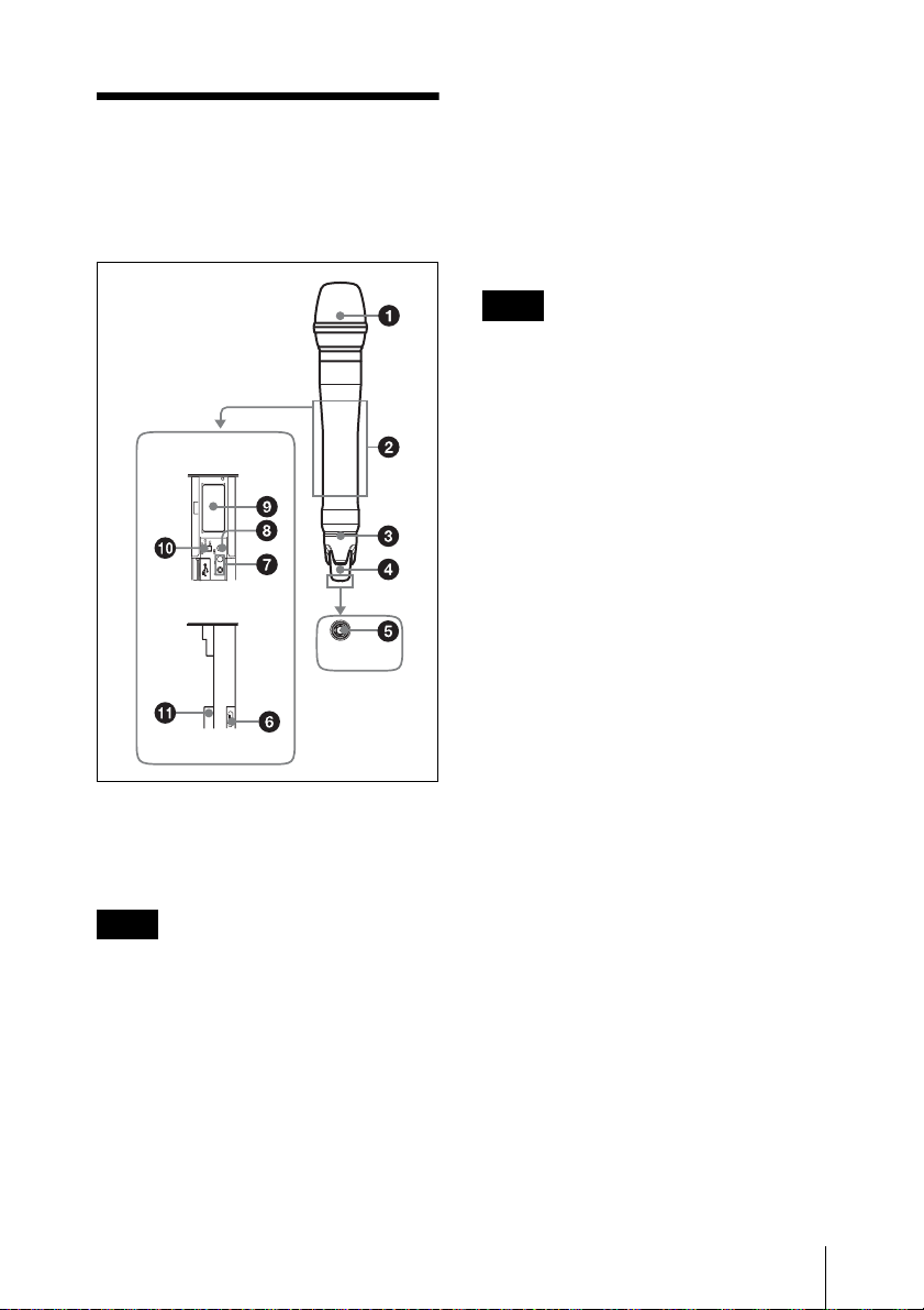
b Grip
Contains operation buttons, display section,
and the battery holder.
Open the grip to make settings or install the
batteries.
For details on how to open the grip, see “Installing
the Batteries” on page 11.
Note
When the grip is open, the metal part of the
grip obstructs the antenna for RF
transmission and wireless remote control
system. To transmit the signal or to use the
wireless remote control function with this
microphone, be sure to close the grip.
c Identification ring
The ring can be replaced with the ones
supplied.
This is useful when multiple microphones
are used in the system.
For details on how to replace the identification ring,
see “Replacing the Identification Ring” on page 12.
d Antenna cover
Holds the antenna for RF transmission and
wireless remote control function.
a Microphone capsule unit (not
supplied)
Mount the microphone capsule unit
securely.
Note
Make sure that the wireless microphone is
turned off before mounting or removing the
microphone capsule unit.
Mounting or removing the unit while the
wireless microphone is turned on may result
in malfunctions.
For details on mounting, refer to the operating
instructions supplied with your microphone capsule
unit.
e POWER indicator
Lights up green when the microphone is
turned on. When the battery is exhausted,
the indicator starts flashing.
f USB connector (Micro USB)
Use this connector to connect an optional
USB keyboard to carry out menu functions
using key operations.
By connecting the digital wireless receiver
to this connector with the supplied USB
cable, you can exchange the encryption key
for encrypted transmission function.
g + or – button
Selects functions or values shown on the
display.
Parts Identification
9
Page 10
Holding down the – button while switching
on the microphone activates the pairing
operation for the wireless remote control
function.
F POWER switch lock indicator
Indicates that the POWER switch is locked,
preventing the microphone from being
accidentally turned off or on.
h SET button
Adjusts displayed function settings and
enters the value.
Holding down the SET button while
switching on the power turns the
microphone on without sending a signal.
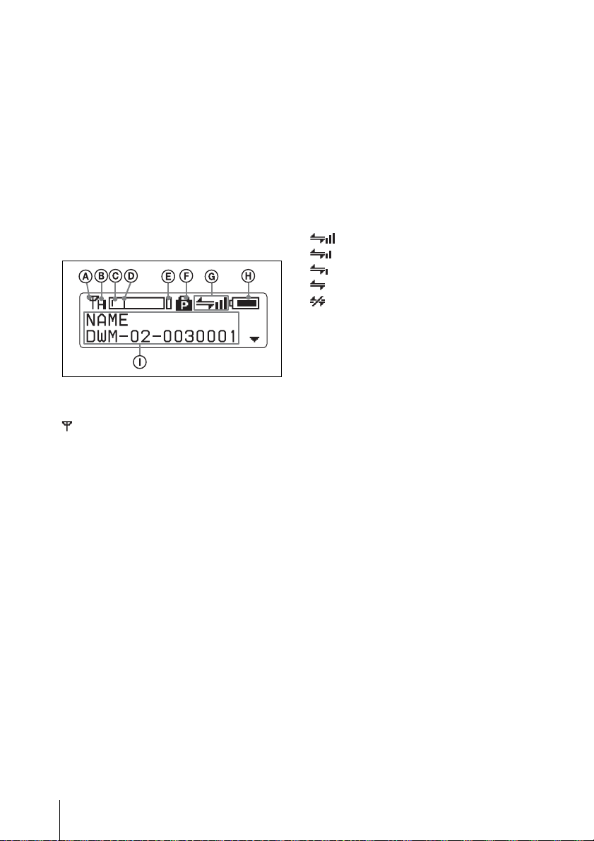
i Display section
A RF transmission indication
Indicates the current transmission status.
: Currently transmitting
—: Transmission stopped
B RF (radio frequency) transmission
power indication
Indicates the current transmission power
setting. You can change the setting with the
RF transmission power setting function.
H: transmitting at 50 mW
M: transmitting at 10 mW
L: transmitting at 1 mW
C Audio input level meter
Indicates the signal input level.
D Reference level gauge
Indicates the reference input level. When
the attenuation is 0 dB, 94 dBSPL is
indicated.
For details, see “Locking the POWER Switch
(POWER SW LOCK)” on page 24.
G Cross Remote condition indication
Indicates the signal transmission condition
of the wireless remote control function (4
levels).
: Good transmission
: Somewhat good transmission
: Somewhat poor transmission
: Poor transmission
: Unable to communicate with paired
receiver
When the wireless remote control function
is off, this indication does not appear.
H Battery indication
Shows the battery condition.
For details, see “Battery indication” on page 11.
I Menu display section
The status of 17 different functions are
displayed here. To select the function, press
the + or – button repeatedly.
For details, See “Setting Menus” on page 21.
j POWER switch
Turns the microphone ON or OFF.
k Battery compartment
Accommodates two LR6 (size AA) alkaline
batteries.
For details on how to insert the batteries, see
“Power Supply” on page 11.
E Peak indicator
Warns of excessive input by lighting up
when the signal is 3 dB below the level at
which distortion begins.
Parts Identification
10
Page 11
Power Supply
The microphone can operate on two LR6
(size AA) alkaline batteries continuously
for about 5 hours at 25 °C (77 °F).
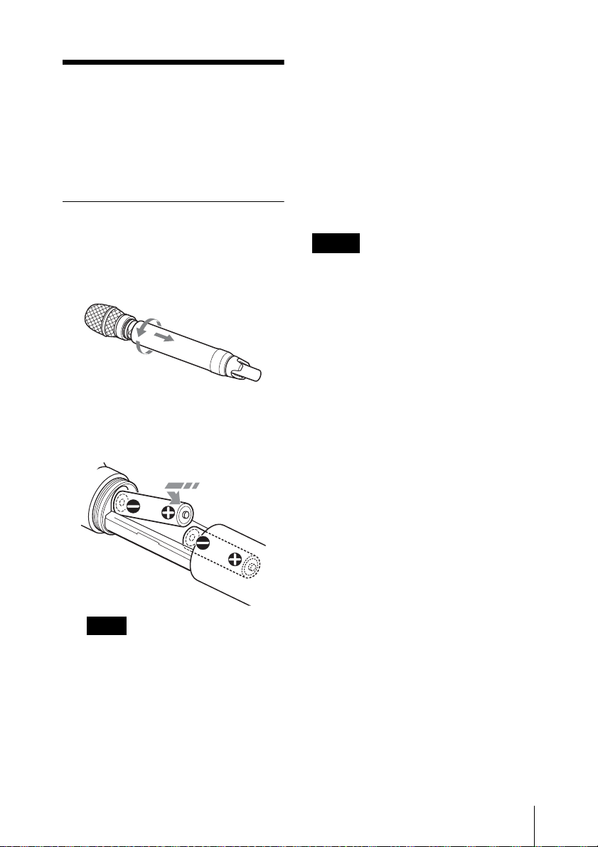
Installing the Batteries
1 Turn the grip in the direction of the
arrow, and pull down the grip until the
battery compartment is shown.
2 Insert two new LR6 (size AA) alkaline
batteries, making sure the polarities are
correct.
3 Close the grip and turn it in the reverse
direction in the step 1 above.
Battery indication
The power status is indicated by eight level
indications.
Replace both batteries when the battery
indication starts to flash.
Be sure to check the expiration date printed
on the new batteries before using them.
Notes
• When BATTERY TYPE is set to
TYPE1, the power status is indicated
based on the use of new LR6 (size AA)
Sony Alkaline batteries. An incorrect
indication may result when a different
kind of batteries, a different brand of
batteries or old batteries are used. If you
plan to use other kind of batteries than
alkaline, set the BATTERY TYPE
function according to the type of batteries
to be used.
• If you plan to use the microphone for a
long period of time, it is recommended
that you replace the batteries with brand
new ones.
Note
To prevent the batteries from touching
each other, push in the second battery
against the spring tension.
Squeezing the batteries into the
compartment while two batteries are
touching may damage the battery
packages.
For details on BATTERY TYPE setting, see “Setting
the Battery Type (BATTERY TYPE)” on page 23.
CAUTION
Danger of explosion if battery is incorrectly
replaced.
Replace only with the same or equivalent
type recommended by the manufacturer.
When you dispose of the battery, you must
obey the law in the relative area or country.
ATTENTION
Il y a danger d’explosion s’il y a
remplacement incorrect de la batterie.
Remplacer uniquement avec une batterie du
même type ou d’un type équivalent
recommandé par le constructeur.
Lorsque vous mettez la batterie au rebut,
vous devez respecter la législation en
Power Supply
11
Page 12

vigueur dans le pays ou la région où vous
vous trouvez.
VORSICHT
Explosionsgefahr bei Verwendung falscher
Batterien. Batterien nur durch den vom
Hersteller empfohlenen oder einen
gleichwertigen Typ ersetzen.
Wenn Sie die Batterie entsorgen, müssen
Sie die Gesetze der jeweiligen Region und
des jeweiligen Landes befolgen.
Attaching the Supplied Accessories
Replacing the Identification Ring
A black ring is attached at the factory.
When multiple microphones are used in the
system, identification rings with different
colors are useful to distinguish a
microphone from another.
Move the ring holder as follows to remove
it.
1 Pull it down.
2 Turn it left.
3 Pull it down.
4 Turn it right.
Attaching the Supplied Accessories
12
5 Pull it down.
Page 13
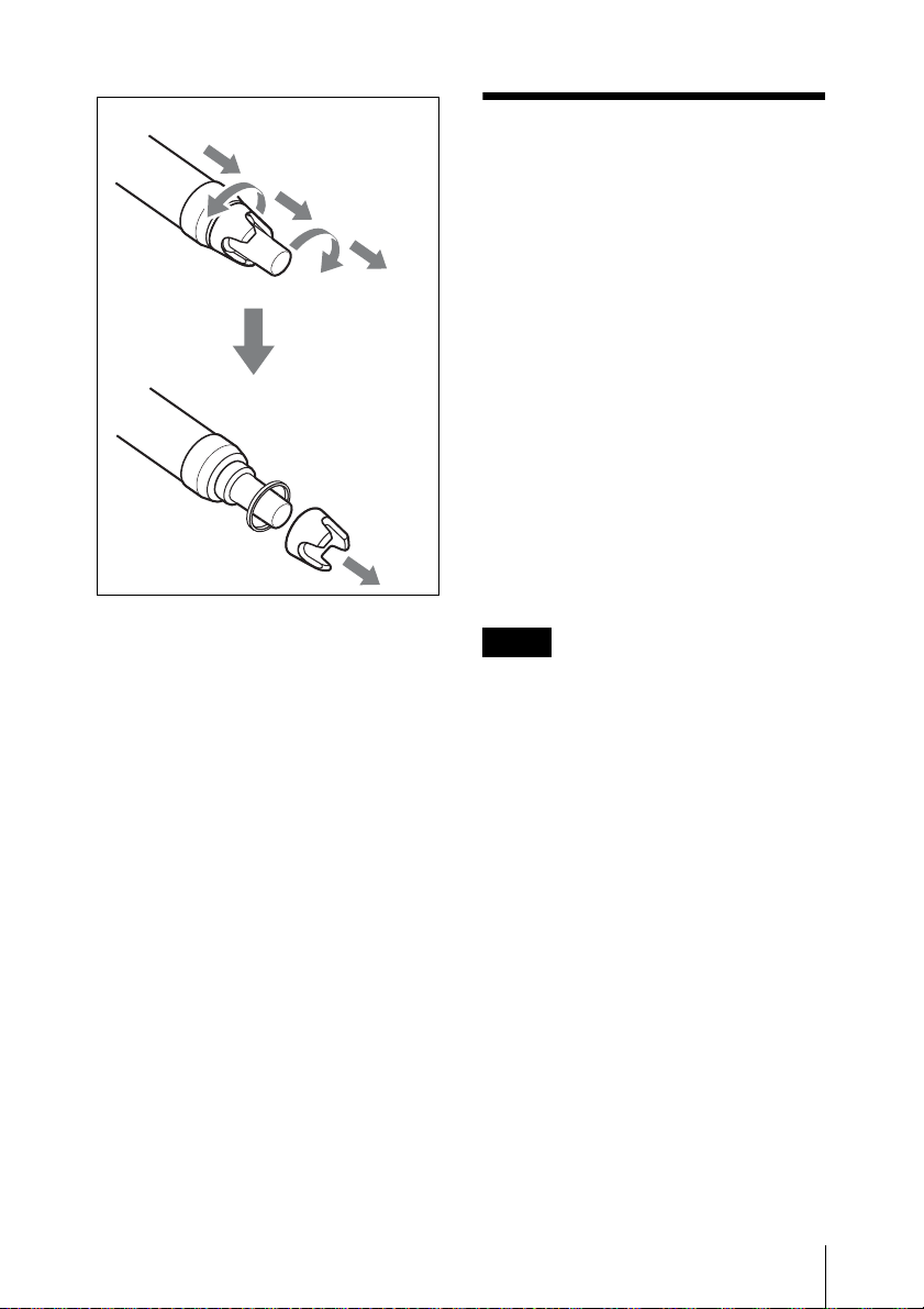
1
2
3
Rotate and
remove the ring
holder to
replace the
identification
ring.
4
5
Setting the Transmission Channel
The microphone provides groups of
interference-free channels. When using
multiple microphones and transmitters at
the same time (simultaneous multi-channel
operations) within the same area, selecting
the same group and using a channel within
that group can prevent signal interference.
To set the transmission channel on the
microphone, first you select the group and
channel using the RF indicator and
scanning functions on the receiver. Next
you set the group and channel parameters to
match the setting on the receiver.
Notes
• Certain transmission channels cannot be
used with the wireless remote control
function.
• “(INCOMPATIBLE WITH RF
REMOTE)” will slide across the display
during group/channel selection for
transmission channels that cannot be
used with the wireless remote control
function.
• When a transmission channel that cannot
be used with the wireless remote control
function is selected, “RESTRICTED BY
GP/CH SETTING” appears on the RF
REMOTE screen and the wireless remote
control function cannot be used. When
using the wireless remote control
function, select transmission channels for
which “(INCOMPATIBLE WITH RF
REMOTE)” does not appear during
group/channel selection.
Setting the Transmission Channel
13
Page 14

Selecting the Group/ Channel
Notes
• Before doing this procedure, use the
BAND function (see page 21) to set the
microphone to the bandwidth of the
receiver you are using.
• The setting for this function cannot be
changed during actual signal
transmission.
Set the microphone group (GP) and channel
(CH) as follows:
For details on groups and channels, refer to “Sony
Digital Wireless Microphone System Frequency
Lists” on the supplied CD-ROM.
For details on menu operation, see “Basic Menu
Operations” on page 20.
1 Turn off the power, and then while
holding down the SET button, turn the
power on.
The signal transmission stops.
Note
To start signal transmission with the
selected channel, turn off the power and
then turn it on again.
To set the group/channel
using the pairing mode of the
Cross Remote
When the microphone is paired with the
receiver, the transmission channel of the
microphone is set to the receiving channel
on the receiver automatically.
For details, see“Pairing With a Receiver” on
page 15.
2 Press the + or – button repeatedly until
the GP/CH indication is displayed.
3 Hold down the SET button until the
item to be set flashes.
4 Press the + or – button repeatedly to
select a group.
5 Press the SET button to enter the
group.
The channel indication starts flashing.
6 Press the + or – button repeatedly to
select a channel.
7 Press the SET button to enter the
channel.
Setting the Transmission Channel
14
Page 15

Using the Cross Remote
down the – button establishes the pairing
immediately.
To carry out pairing through menu
operations on the microphone, do the
following.
This microphone is equipped with a
wireless remote control function that can be
used to set the parameters (low-cut filter,
attenuation operation, power save mode,
etc.) of the microphone through the receiver
or other devices. This function makes it
easier to operate and manage the
microphone system while in the field.
This wireless control is 2.4 GHz
IEEE802.15.4 compliant and has no effect
on the RF band of digital wireless audio.
This function is activated when pairing is
established between the microphone and
the receiver using the RF REMOTE
function.
Pairing must be done first before the
wireless remote control function can be
used.
Note
If “RESTRICTED BY GP/CH SETTING”
appears on the RF REMOTE screen, the
wireless remote control function cannot be
used. To use the wireless remote control
function, select a different transmission
channel.
For details on how to change the transmission
channel, see “Setting the Transmission Channel” on
page 13.
Pairing With a Receiver
Pairing links the microphone with the
receiver which the wireless remote control
function is to be used.
When the microphone has been paired with
a receiver through the receiver operation,
turning on the microphone while holding
1 Set the receiver to be used for
controlling the microphone to pairing
mode.
For details, refer to the operating instructions
supplied with the receiver.
2 Press the + or – button repeatedly until
the RF REMOTE indication is
displayed.
3 Hold down the SET button until the
item to be set flashes.
4 Press the + or – button repeatedly to
select PAIRING.
5 Press the SET button to enter.
The microphone sends a pairing
request to the receiver which is on
pairing mode.
Before established pairing, if you press
any operation key on the microphone,
pairing mode will be cancelled.
When pairing has been established, the
wireless remote control condition level
(indicated by ) goes up, RF
REMOTE turns on, and the remote
control function becomes operative.
When “Pairing fail” is
displayed
• Successful communication between the
microphone and the receiver did not
occur within a given amount of time.
Perform pairing again.
• Pairing has been performed with the grip
open. When the internal antenna is
covered with the grip, pairing may not be
Using the Cross Remote
15
Page 16

carried out. After setting the microphone
ready for pairing in step 5 above, be sure
to close the grip.
To use the Cross Remote with
a previous pairing
In the RF REMOTE indication, select ON.
Notes
• When you set RF REMOTE to ON, the
microphone will communicate with the
receiver to which it was previously
paired. To use the wireless remote
control function with another receiver,
you must perform the pairing procedure
for that receiver.
• Multiple microphones/transmitters
cannot be paired with the same receiver.
• If you reset all parameters by using the
FACTORY PRESET function (see page
25), the pairing setting of the microphone
is also cleared.
The following microphone settings
can be done from the remote control:
• Microphone name setting
• Frequency band/group/channel selection
• RF transmission power setting
• Attenuator for the audio input setting
• Low-cut filter setting
• Power save setting
• Resetting accumulated use time
• Internal signal setting
• POWER switch lock setting
Notes on the Cross Remote
The wireless remote control function on the
microphone uses the 2.4-GHz band and
may thus be subject to interference from
other devices.
• When pairing fails (“Pairing fail” is
displayed), successful communication
between the microphone and the receiver
has not occurred within a given amount
of time. Pairing may be harder to do
when another receiver is engaged in
pairing nearby.
• When it becomes hard to use the remote
control, the remote control may be
improved by switching the wireless
remote control function off, then on again
in the RF REMOTE display, then repairing with the microphone (change to a
channel with less interference).
For details on menu operation, see “Setting Menus”
on page 21.
To perform remote control, the receiver must be
equipped with a control function for the setting you
want to control. For details, refer to the operating
instructions supplied with the receiver.
To cancel the Cross Remote
In the RF REMOTE indication, select OFF.
Using the Cross Remote
16
Page 17

Using the Encrypted Transmission Function
To prevent hacking of the signal, the
microphone scrambles the signal during
transmission. To use this function, select
one of the following encrypted transmission
modes:
Secure key mode: An encryption key
that is automatically generated by the
microphone is used by both the microphone
and receiver in this one-to-one encrypted
transmission method.
Password mode: You choose a
password of up to eight characters that can
be set for multiple microphones/
transmitters and receivers. This enables
encrypted transmission within a group.
Note
Make sure the same mode is set on the
microphone/transmitter and receiver.
Using Secure Key Mode
(SECURE KEY)
Use this mode for one-to-one encrypted
transmission between one microphone and
one receiver.
An encryption key that cannot be read from
the outside is automatically generated by
the microphone. This key is transmitted to
the receiver through a USB connection or
the RF REMOTE function, enabling
encrypted transmission to take place.
The encryption key used by the microphone
and receiver is newly generated for each
key transmission, resulting in highly secure
communication.
The encryption key used between the
microphone and the receiver is saved when
the power is turned off, so the encrypted
transmission can be resumed the next time
the power is turned on.
1 Preparing the microphone (this unit)
1 Hold down the SET button until
the item to be set flashes in
ENCRYPTION indication on the
microphone.
2 Press the + or – button repeatedly
to select SECURE KEY, and then
press the SET button.
2 Preparing the receiver
Select SECURE KEY on the receiver
that receives the encryption key.
For details on receiver operations, refer to the
operating instructions supplied with the
receiver.
3 Exchanging the encryption key
On the receiver, select USB or
REMOTE (wireless remote) as the
method for encryption key exchange.
When the RF REMOTE function is
off, REMOTE cannot be selected.
Note
When the receiver does not support
encryption key exchange through USB
connection, select REMOTE.
For details on the receiver, refer to the
operating instructions supplied with the
receiver.
When you select USB:
Connect the microphone to the
receiver with the supplied USB cable
and USB adapter cable.
Using the Encrypted Transmission Function
17
Page 18
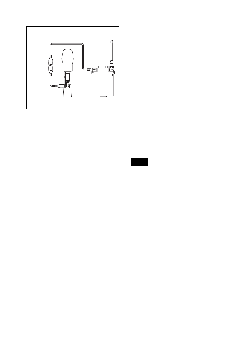
USB cable (supplied)
2 Press the + or – button repeatedly to
select PASSWORD, and then press the
SET button.
3 Input a password of up to eight
characters on the microphone.
To enter a password, use the procedure
described in “Naming of Microphone
(NAME)” on page 21.
USB adapter
cable
(supplied)
For details on receiver operations, refer to the
operating instructions supplied with the
receiver.
When you select REMOTE:
The microphone searches for a
receiver that it has been paired with.
After the microphone detects the
receiver, the microphone exchanges
the encryption key with receiver and
encrypted transmission begins.
Using Password Mode
(PASSWORD)
Set this mode when multiple microphones/
transmitters are paired with multiple
receivers for encrypted transmission.
If both microphones/transmitters and
receivers are set with the same userdesignated password, the audio signal can
be decoded. This mode is useful when
multiple microphones/transmitters and
receivers are used as a single group, or
when the audio signal from one
microphone/transmitter is received by
multiple receivers at the same time.
4 Set the encrypted transmission
function setting on the receiver to
PASSWORD.
5 Set the same password that was set on
the microphone.
For details on receiver operations, refer to the
operating instructions supplied with the
receiver.
Note
It is recommended that you change the
password periodically.
1 Hold down the SET button until the
item to be set flashes in the
ENCRYPTION indication on the
microphone.
Using the Encrypted Transmission Function
18
Page 19
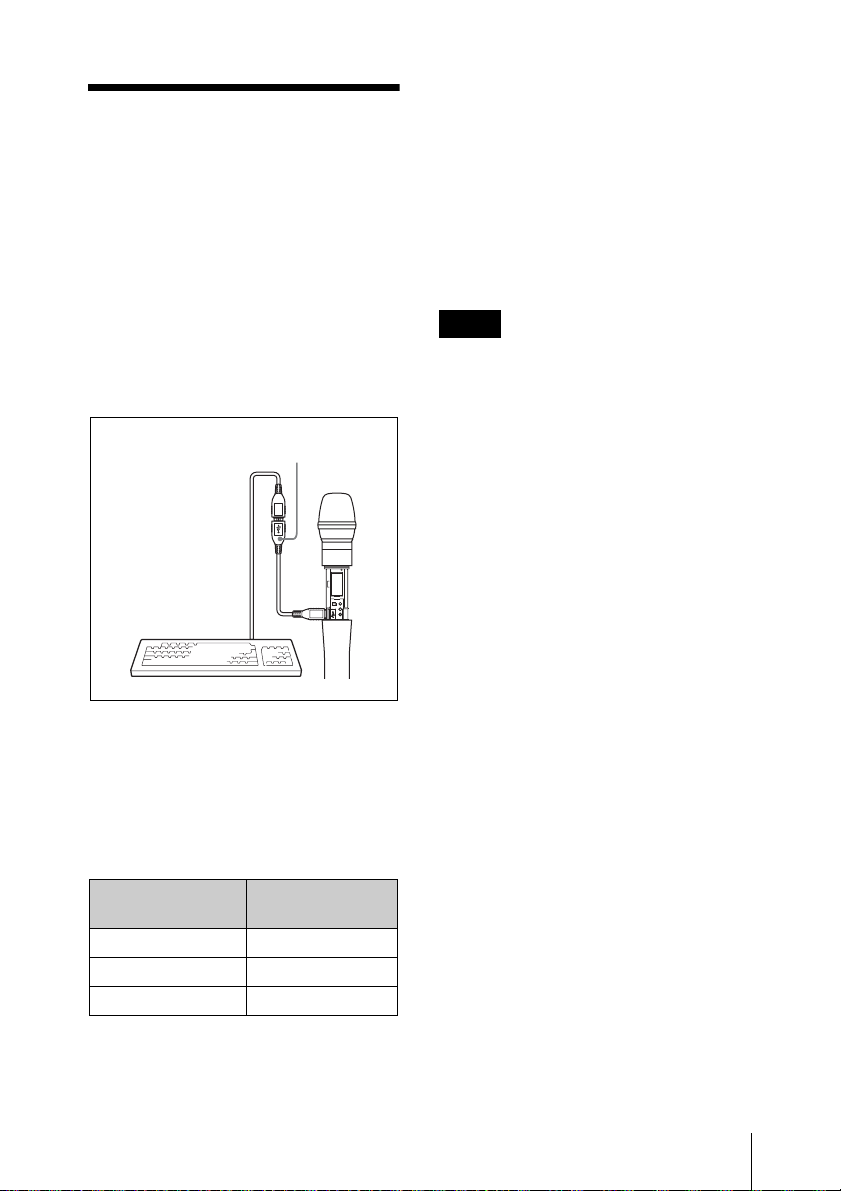
Using a USB Keyboard
Connecting an optional USB keyboard to
the microphone allows you to perform
menu operations and enter your name and
password for the encrypted transmission
function from the keyboard.
A Micro USB connector is used on the
microphone. For this reason, use the
supplied USB adapter cable.
USB adapter cable (supplied)
Menu operations with a USB
keyboard
You can use a USB keyboard to perform the
same menu operations that you do on the
microphone.
The microphone buttons correspond to the
following keys on a USB keyboard:
Characters that can be entered from
a USB keyboard: (space), 0, 1, 2, 3, 4, 5,
6, 7, 8, 9, A, B, C, D, E, F, G, H, I, J, K, L,
M, N, O, P, Q, R, S, T, U, V, W, X, Y, Z, !,
#, &, $, @, +, -, =, _, (, ), [, ]
(Passwords may consist of the numbers 0 to
9 and letters A to Z only.)
Special key: Backspace (BS) and Delete
(DEL) keys.
Notes
• The number keys on the keyboard cannot
be used.
• This microphone is compatible with
English-language keyboards only.
• USB keyboards with multiple functions,
such as USB hub and pointing device,
cannot be used.
• Power to the connected keyboard is
supplied by the USB connector on the
microphone. The power rating is 100
mA. Keyboards that consume more
power than that cannot be used.
• Do not leave the microphone connected
to the keyboard when not in use. If you
do, the batteries in the microphone will
be drained more quickly.
• Text editing should be done with the
alphabet, BS, DEL, and Enter keys.
Buttons on the
microphone
SET ENTER
+ R
– r
USB keyboard
To enter a text
With a USB keyboard, you can enter names
and passwords for encrypted transmissions.
Using a USB Keyboard
19
Page 20
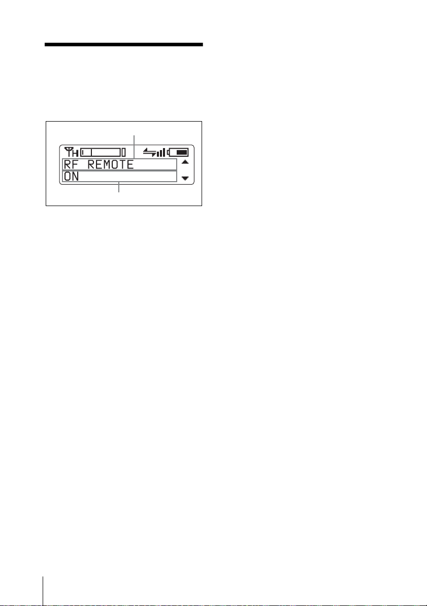
Basic Menu Operations
Function name
Item to be set
1 Press the + or – button repeatedly until
the function to be set appears.
2 Hold down the SET button until the
item to be set flashes.
3 Press the + or – button to change the
setting.
4 Press the SET button to enter the
setting.
• BRIGHTNESS (display brightness)
setting
• DIMMER MODE (automatic dimming
of the display) setting
• FACTORY PRESET (factory setting)
function
• VERSION (software version) indication
Types of menu:
• NAME (microphone name) setting
• BAND (frequency band) selection
• GP/CH (group/channel) selection
• RF POWER (RF transmission power)
setting
• INPUT LEVEL (audio input level)
setting
• LCF (low-cut filter) setting
• POWER SAVE setting
• BATTERY TYPE (battery type) setting
• TIME (accumulated use time) indication
• ENCRYPTION (encrypted transmission
function) setting
• INTERNAL SG (internal signal
generator) function
• POWER SW LOCK (POWER switch
lock) function
• RF REMOTE (wireless remote control)
function
Basic Menu Operations
20
Page 21

Setting Menus
The functions and parameters of the settings
menu are explained here. Underlined items
are the factory setting.
Naming of Microphone
(NAME)
You can specify a microphone name of up
to 16 characters. The factory setting for the
microphone name is the model name and
serial number. The microphone name is
sent to the receiver as metadata and is used
by the receiver to distinguish between
different microphones/transmitters.
+: The first press on the + button displays
the character set. You can then use the + and
– buttons to select the desired character.
And then, pressing the SET button adds the
selected character to the end of the current
name.
– : Deletes the last character in the current
name.
SET: Enters the character or edited name.
Note
You cannot insert or delete a character in
the middle of the name.
Using wireless remote control, this function
can be controlled from the receiver and
other devices.
For details on wireless remote control function, see
“Using the Cross Remote” on page 15.
For details, see “Using a USB Keyboard” on
page 19.
Selecting the Frequency Band (BAND)
Match the frequency range on this
microphone to that of the Sony digital
wireless receiver.
See “Carrier Frequencies and Channel
Steps” on page 32 for differences in
frequency ranges that can be set for optional
receivers combined with this transmitter.
For details about the frequency range of each band,
refer to “Sony Digital Wireless Microphone System
Frequency Lists” on the supplied CD-ROM.
Using wireless remote control, this function
can be controlled from the receiver and
other devices.
For details on wireless remote control function, see
“Using the Cross Remote” on page 15.
Notes
• The setting for this function cannot be
changed during actual signal
transmission. To change the setting, turn
off the microphone first. Then, while
holding down the SET button, turn the
power on. Then change the setting after
the signal transmission has stopped.
• Be sure to select the group/channel right
after selecting the frequency band. To
start signal transmission with the selected
frequency band/group/channel, turn off
the power and then turn it on again.
Selecting the Group/ Channel (GP/CH)
To edit with a keyboard
You can enter data from an optional
keyboard connected to the USB connector.
See “Carrier Frequencies and Channel
Steps” on page 32 for factory settings.
For details, see “Selecting the Group/Channel” on
page 14.
Setting Menus
21
Page 22
Using wireless remote control, this function
can be controlled from the receiver and
other devices.
For details on wireless remote control function, see
“Using the Cross Remote” on page 15.
Setting the RF Output Power (RF POWER)
You can set the RF output power.
1 mW (LOW): transmitted by 1 mW
10 mW (MID)
50 mW (HIGH): transmitted by 50 mW
Notes
• The setting for this function cannot be
changed during actual signal
transmission. To change the setting, turn
off the microphone first. Then, while
holding down the SET button, turn the
: transmitted by 10 mW
power on. And then, change the setting
after the signal transmission has stopped.
• To start signal transmission with the
selected RF output power setting, turn off
the power and then turn it on again.
Using wireless remote control, this function
can be controlled from the receiver and
other devices.
For details on wireless remote control function, see
“Using the Cross Remote” on page 15.
Setting the Audio Input Level (INPUT LEVEL)
You can set the input level to the analog
head amp.
Press the + or – button repeatedly to select
the appropriate attenuation level.
The reference levels for the various settings
are as follows:
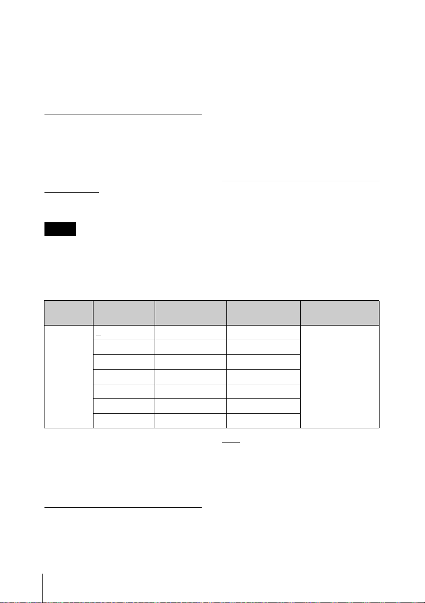
Input Attenuation
MIC 0
(dB)
3–49–13
6–46–10
9–43–7
3 dB steps 3 dB steps 3 dB steps
18 –34 +2
21 –31 +5
Using wireless remote control, this function
can be controlled from the receiver and
other devices.
For details on wireless remote control function, see
“Using the Cross Remote” on page 15.
Low-cut Filter Setting (LCF)
The frequency of the low-cut filter can be
set.
Setting Menus
22
Reference input
level (dBu)
–52 –16 36
Maximum input
level (dBu)
Headroom (dB)
OFF: Turns off the low-cut filter.
20 30 40 50 60 70 80 90 100
120 140 160 180 200 220 (Hz):
Low-cut filter is set according to the
selected frequency.
Using wireless remote control, this function
can be controlled from the receiver and
other devices.
Page 23

For details on wireless remote control function, see
“Using the Cross Remote” on page 15.
Power Save Setting (POWER
SAVE)
To conserve power, this setting allows you
to put all microphone functions to sleep.
Note
The characteristics of batteries change
according to battery type and
environmental conditions. It is
recommended that you learn the
characteristics of batteries you use before
using them.
ACTIVE: The microphone operates
normally.
SLEEP: The sleep function is on. During
sleep, the POWER indicator flashes at 2second intervals.
To change back to normal
operation
During sleep, press the SET, +, or – button.
You can also use the wireless remote
control to change the receiver back to
normal operation.
For details on wireless remote control function, see
“Using the Cross Remote” on page 15.
Note
If the microphone is turned off while power
save setting is set to “SLEEP”, the setting
will change to “ACTIVE” automatically.
Setting the Battery Type
(BATTERY TYPE)
Set this item according to the type of
batteries you use to obtain accurate battery
power status indication.
Displaying the
Accumulated Use Time
(TIME)
You can display the accumulated battery
use time as a rough estimate of total
microphone usage.
The factory setting is “00:00”.
To reset the accumulated time
indication
1 Hold down the SET button until the
time indication flashes.
2 Press the – button so “00:00 RESET”
appears, and then press the SET
button.
Using wireless remote control, this function
can be controlled from the receiver and
other devices.
For details on wireless remote control function, see
“Using the Cross Remote” on page 15.
Setting the Encrypted
Transmission Function
(ENCRYPTION)
TYPE1
: The power status is indicated
based on characteristics of new LR6 (size
AA) Sony Alkaline batteries. Select this for
LR6 (size AA) alkaline batteries.
TYPE2: Select this for rechargeable
nickel-metal-hydride batteries.
TYPE3: Select this for lithium batteries.
You can set the encrypted transmission
function.
SECURE KEY: Sets the secure key
method.
PASSWORD: Sets the password method.
Setting Menus
23
Page 24

OFF: The encrypted transmission function
is not used.
For details, see “Using the Encrypted Transmission
Function” on page 17.
Generating an Internal Signal (INTERNAL SG)
This microphone generates a 1-kHz
reference level sine wave that can be used to
adjust or check the audio level of the
receiver or the system that you are using.
This internal signal is outside the control of
the attenuator.
1kHz: A 1-kHz internal signal is generated.
: An internal signal is not generated.
OFF
Note
If the microphone is turned off while the
reference signal function is on, the function
will turn off automatically.
Using wireless remote control, this function
can be controlled from the receiver and
other devices.
For details on wireless remote control function, see
“Using the Cross Remote” on page 15.
Using wireless remote control, this function
can be controlled from the receiver and
other devices.
For details on wireless remote control function, see
“Using the Cross Remote” on page 15.
Cross Remote (RF REMOTE)
This function must be set to allow the
wireless remote control function to be used
between the microphone and receiver.
OFF
: Stops the wireless remote control
function.
ON: Starts the wireless remote control
function with the previously paired
receiver.
PAIRING: Executes a new pairing.
For details, see “Pairing With a Receiver” on
page 15.
Note
If “RESTRICTED BY GP/CH SETTING”
appears on the RF REMOTE screen, the
wireless remote control function cannot be
used. To use the wireless remote control
function, select a different transmission
channel.
Locking the POWER Switch (POWER SW LOCK)
The POWER switch can be locked to
prevent the microphone from being
accidentally turned off or on.
Even when the POWER switch is locked,
all parts of the microphone other than the
POWER switch remain functional.
UNLOCK
locked.
LOCK: The POWER switch is locked.
When LOCK is selected, the POWER
switch lock icon appears in the display.
Setting Menus
24
: The POWER switch is not
For details on how to change the transmission
channel, see “Setting the Transm ission Channel” on
page 13.
Setting the Brightness of the Display (BRIGHTNESS)
Ten levels of brightness can be selected for
the organic light-emitting diode display.
The selectable settings are the following:
(Dark) 1 2 3 4 5 6 7 8 9 10 (Bright)
Page 25

Automatic Dimming of the
Display
(DIMMER MODE)
Displaying the Software
Version
(VERSION)
The organic light-emitting diode display
can be set to dim or turn off after a certain
amount of time.
AUTO OFF
seconds. The display goes on again when
you press the SET, +, or – button.
AUTO DIMMER: The display dims after
30 seconds. The display becomes bright
again when you press the SET, +, or –
button.
ALWAYS ON: The display stays on at the
brightness level set with the BRIGHTNESS
function.
: The display turns off after 30
Resetting Parameters to
Their Factory Settings
(FACTORY PRESET)
All parameter settings can be returned to
their factory settings.
Holding down the SET button until a
message appears asking for confirmation.
Press the + or – button repeatedly to select
YES, and then press the SET button to
enter. The microphone parameters are reset
to their factory settings.
Notes
• The setting for this function cannot be
changed during actual signal
transmission. To change the setting, turn
off the power first. Then while holding
down the SET button, turn the power on.
Then change the setting after the signal
transmission has stopped.
• To start signal transmission with the
factory parameter settings, turn off the
power and then turn it on again.
The version of the microphone software can
be displayed.
Setting Menus
25
Page 26
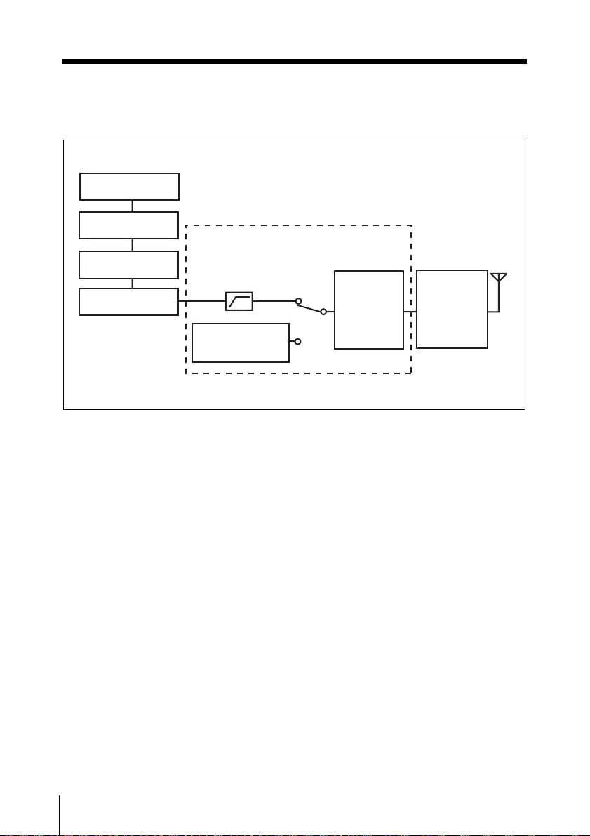
Block Diagram
Microphone
capsule
Attenuator
Head amp.
Low-cut filter
A/D converter
Internal SG
Digital signal processor
Audio codec
modulator
High-
frequency
circuit
26
Block Diagram
Page 27
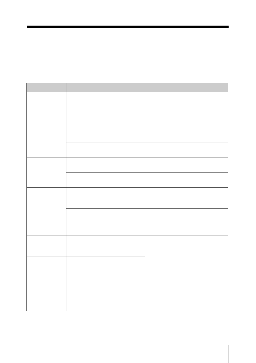
Troubleshooting
If you encounter a problem using this microphone, use the following checklist to find a
solution. For any problems with the receiver, refer to the operating instructions supplied with
the receiver. If the problem persists, consult your Sony dealer.
Symptom Meanings Remedy
The
microphone
does not turn
on.
The batteries
drain quickly.
Interruptions in
the reception
occurs.
There is no
sound.
The sound is
weak.
There is
distortion in the
sound.
The bass is
weak.
The batteries are inserted
backwards in the battery
compartment.
The batteries are exhausted. Replace the batteries with new
Manganese batteries are being
used.
The microphone is being used
under cold conditions.
The microphone is too far from
the receiver.
The transmission power setting
is set to “L: 1mW”.
The channel setting on the
microphone is different from that
on the receiver.
The setting of the encrypted
transmission function on the
receiver is different from that on
the microphone.
The attenuator is set too high for
the audio input level of the
microphone.
The attenuator is set too low for
the audio input level of the
microphone.
The frequency of the low-cut
filter is set too high.
Reinsert the batteries with the
correct orientation (see page 11).
ones.
Use alkaline batteries.
The batteries drain quickly under
cold conditions.
Decrease the distance to the
receiver and check the reception.
Increase the transmission power
(see page 22).
Use the same channel setting on
both the microphone and receiver.
Confirm that the setting of the
encrypted transmission function is
the same on both the microphone
and the receiver (see page 17).
While monitoring the audio input
level meter on the microphone or
the receiver, set the attenuator to
an appropriate level (see page 22).
While monitoring the sound,
decrease the low-cut filter
frequency to a level that produces
the proper sound quality (see page
22).
Troubleshooting
27
Page 28

Symptom Meanings Remedy
There is too
much bass.
The power
does not turn
off even though
the POWER
switch is turned
to OFF.
Wireless
remote control
is not possible.
The USB
keyboard does
not work.
The display is
too dark.
The microphone produces
excessive bass because the
frequency response of the
microphone extends into the low
range.
The POWER switch is locked. Turn off the POWER SW LOCK
Pairing has not been established
between the microphone and
receiver.
The receiver is too far from the
microphone for communication
to occur.
The microphone that was paired
with the receiver has been
paired with another receiver.
You are using a USB keyboard
that is not compatible with the
microphone.
The display brightness is set to
low.
Use the low-cut filter to cut the
bass (see page 22).
function (see page 24).
Carry out pairing (see page 15).
Check the wireless remote control
condition level. If it is low,
decrease the distance between
the microphone and the receiver
(see page 10).
On the receiver, carry out pairing
again with the microphone that you
want to control.
Check the conditions for using a
USB keyboard with the
microphone (see page 19).
Adjust the brightness of the display
(see page 24).
28
Troubleshooting
Page 29

Important Notes on Operation
Notes on Using the Microphone
• The digital wireless microphone system
product must be used within a
temperature range of 0 °C to 50 °C
(32°F to 122°F).
• Operating the microphone near electrical
equipment (motors, transformers, or
dimmers) may cause it to be affected by
electromagnetic induction. Keep the
microphone as far from such equipment
as possible.
• The presence of the lighting equipment
may produce electrical interference over
the entire frequency range. Position the
microphone so that interference is
minimized.
• To avoid degradation of the signal-tonoise ratio, do not use the microphone in
noisy places or in locations subject to
vibration, such as the following:
- near electrical equipment, such as
motors, transformers or dimmers
- near air conditioning equipment or
places subject to direct air flow from
an air conditioner
- near public address loudspeakers
- where adjacent equipment might
knock against the tuner
Keep the microphone as far from such
equipment as possible or use buffering
material.
On Cleaning
• If the microphone is used in a very humid
or dusty place or in a place subject to an
active gas, clean its surface as well as the
connectors with a dry, soft cloth soon
after use. Lengthy use of the microphone
in such places or not cleaning it after its
use in such places may shorten its life.
• Clean the surface and the connectors of
the microphone with a dry, soft cloth.
Never use thinner, benzene, alcohol or
any other chemicals, since these may mar
the finish.
Notes on Simultaneous MultiChannel Operation
• Keep the microphone at least 30 cm (11 7/
inches) away from another transmitter/
microphone.
When the distances between transmitters
and microphones need to be closer than the
distances above, use a grouping system for
multi-channel systems that include both
digital wireless and analog wireless devices.
For details, refer to “Sony Digital Wireless
Microphone System Frequency Lists” on the
supplied CD-ROM.
• When only digital wireless microphones
are being used, keep the microphone at
least 4 m (13 feet) away from the antenna
of a receiver for up to 10 channels, and at
least 6 m (20 feet) away for 11 or more
channels.
• When a mixture of digital and analog
wireless microphones/transmitters is
being used, keep the microphone at least
6 m (20 feet) away from the antenna of a
receiver.
• This system should be kept at least 100 m
(328 feet) away from any analog wireless
systems using the same frequency when
both are being used in a wide area with no
walls or obstructions.
• If you experience noise, increase the
distance between the microphone and
receiver or decrease the transmission
power on the microphone.
8
Important Notes on Operation
29
Page 30

To prevent electromagnetic
interference from portable
communication devices
The use of portable telephones and
other communication devices near
the DWM-02 may result in
malfunction and interference with
audio signals. It is recommended that
portable communication devices near
the DWM-02 be turned off.
Specifications
Transmitting section
Oscillator type
Crystal-controlled PLL synthesizer
RF power output
1 mW/10 mW/50 mW (e.r.p)
selectable
Antenna type
Helical antenna
Occupied RF bandwidth
192 kHz or less
Audio delay
1.5 ms
Allowable deviation of transmission
frequency
±6.5 ppm
Type of emission
G1E or G1D
Modulation method
π/4 Shift QPSK
Audio section
Maximum input level
–16 dBu (with 0 dB attenuator)
Audio attenuator adjustment range (pad)
0 to 21 dB (3 dB steps)
Input impedance
10 kΩ or more
Frequency response
20 Hz to 22 kHz
30
General
Operating voltage
3 V DC, with two LR6 (AA)
alkaline batteries
Battery life
Continuous operating time
5 hours (at 25 °C (77 °F), 10-mW
output using Sony LR6 (AA)size alkaline batteries with the
Specifications
Page 31
wireless remote control
function off and DIMMER
MODE set to AUTO OFF, and
with the CU-C31 Sony capsule
unit mounted)
Operating temperature
0 °C to 50 °C (32 °F to 122 °F)
Storage temperature
–20 °C to +60 °C (–4 °F to +140 °F)
Wireless remote control
2.4-GHz IEEE802.15.4 compliant
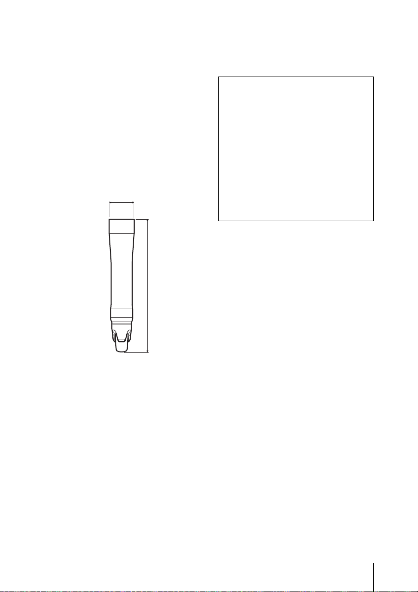
Dimensions (unit: mm (inches))
ø37.1
1
(1
/2)
(7
194
3
Design and specifications are subject to
change without notice.
Note
Always verify that the unit is operating
properly before use. SONY WILL NOT
BE LIABLE FOR DAMAGES OF ANY
KIND INCLUDING, BUT NOT
LIMITED TO, COMPENSATION OR
REIMBURSEMENT ON ACCOUNT
OF THE LOSS OF PRESENT OR
PROSPECTIVE PROFITS DUE TO
FAILURE OF THIS UNIT, EITHER
DURING THE WARRANTY PERIOD
OR AFTER EXPIRATION OF THE
WARRANTY, OR FOR ANY OTHER
REASON WHATSOEVER.
/4)
Mass approx. 235 g (8 oz)
including batteries
Supplied accessories
Identification ring (1 set)
Microphone holder (1)
USB adapter cable (1)
USB cable (1)
Carrying case (1)
Stand adaptor (1)
For the model available in the
U.S.A.: PF
1
/2 to W5/8 type
For the model available in
Europe.: PF1/2 to W3/8 type
Operating Instructions (1)
CD-ROM (1)
Specifications
31
Page 32
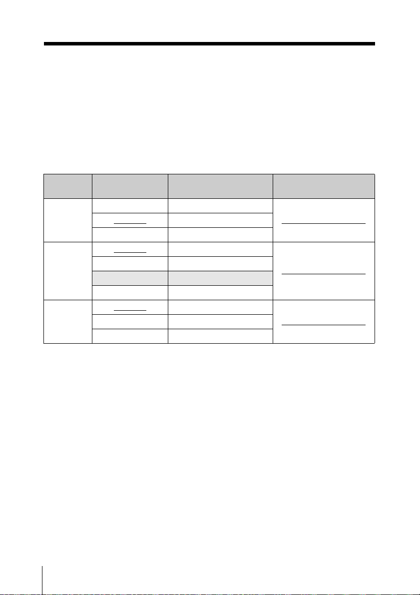
Carrier Frequencies and Channel Steps
Underlined items are the factory setting.
US models
Channel step: 25 kHz
Model No. Frequency band Frequency
TV14-17 470.125 - 493.875 MHz
U1424
U3040
U4250
TV18-21 494.125 - 517.875 MHz
TV22-25 518.125 - 541.875 MHz
TV30-33
TV34-36 590.125 - 607.875 MHz
TV37 Not available
TV38-41 614.125 - 637.875 MHz
TV42-45
TV46-49 662.125 - 685.875 MHz
TV50-51 686.125 - 697.875 MHz
566.125 - 589.875 MHz
638.125 - 661.875 MHz
Group/channel
(factory setting)
00 1801 494.125 MHz
00 3001 566.125 MHz
00 4201 638.125 MHz
Carrier Frequencies and Channel Steps
32
Page 33
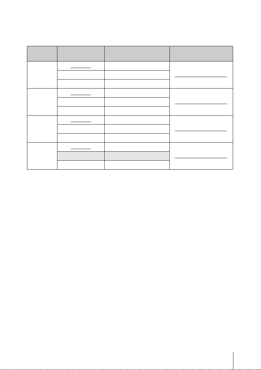
European models
Channel step: 25 kHz
Model No. Frequency band Frequency
CE3338
CE4248
CE5157
CE6267
TV33-35
TV36-37 590.025 - 606.000 MHz
TV38-40 606.025 - 630.000 MHz
TV42-44
TV45-47 662.025 - 686.000 MHz
TV48-50 686.025 - 710.000 MHz
TV51-53
TV54-56 734.025 - 758.000 MHz
TV57-59 758.025 - 782.000 MHz
TV62-64
TV65-66 Not available
TV67-69 838.025 - 862.000 MHz
566.025 - 590.000 MHz
638.025 - 662.000 MHz
710.025 - 734.000 MHz
798.025 - 822.000 MHz
Group/channel
(factory setting)
00 3301 566.125 MHz
00 4201 638.125 MHz
00 5101 710.125 MHz
00 6201 798.125 MHz
Carrier Frequencies and Channel Steps
33
Page 34

Carrier Frequencies and Channel Steps
34
Page 35

Carrier Frequencies and Channel Steps
35
Page 36

Sony Corporation
Printed in Japan
 Loading...