

Sony DVP-NS705V User Manual
CD/DVD
Player
Operating Inst ructions
3-075-802-11(1)
DVP-NS705V
DVP-NS905V
© 2002 Sony Corporation

WARNING
Welcome!
To prevent fire or shock
hazard, do not expose the
unit to rain or moisture.
To avoid electrical shock, do
not open the cabinet. Refer
servicing to qualified
personnel only.
Mains lead must only be
changed at a qualified
service shop.
This appliance is classified as a
CLASS 1 LASER product. The
CLASS 1 LASER PRODUCT
MARKING is located on the rear
exterior.
CAUTION
The use of optical instruments with
this product will increase eye
hazard. As the laser beam used in
this CD/DVD player is harmful to
eyes, do not attempt to disassemble
the cabinet.
Refer servicing to qualified
personnel only.
Notice for customers in the
United Kingdom and
Republic of Ireland
A moulded plug complying with
BS1363 is fitted to this equipment
for your safety and convenience.
Should the fuse in the plug
supplied need to be replaced, a 5
AMP fuse approved by ASTA or
BSI to BS1362, (i.e., marked with
or mark) must be used.
If the plug supplied with this
equipment has a detachable fuse
cover, be sure to attach the fuse
cover after you change the fuse.
Never use the plug without the fuse
cover. If you should lose the fuse
cover, please contact your nearest
Sony service station.
Precautions
Safety
• This unit operates on 220 – 240
V AC, 50/60 Hz. Check that the
unit’s operating voltage is
identical with your local power
supply.
• To prevent fire or shock hazard,
do not place objects filled with
liquids, such as vases, on the
apparatus.
Installing
• Do not install the unit in an
inclined position. It is designed
to be operated in a horizontal
position only.
• Keep the unit and discs away
from equipment with strong
magnets, such as microwave
ovens, or large loudspeakers.
• Do not place heavy objects on
the unit.
Thank you for purchasing this
Sony CD/DVD Player. Before
operating this player, please read
this manual thoroughly and retain
it for future reference.
2

Precautions
On safety
• Caution – The use of optical instrumen ts
with this p roduct wi ll increase e ye hazard.
• S houl d any so lid objec t or liqui d fa ll int o
the cabinet, unplu g the player and have it
checked by quali f ie d personnel before
operating it any further.
On power sources
• T he playe r is not di sconnect ed from the AC
power source (mains) as long as it is
connected to the wall outlet, even if the
player itself has been turned off.
• If you are not going to use the player for a
long time, be sure to disconnect the pla yer
from the wall outlet. To disconnect the AC
power cord (mai ns lead), grasp the p lu g
itself; never pull the cord.
On placement
• Place the player in a location with adequate
ventilation to prevent heat build-up in the
player.
• Do not place the player on a soft surface
such as a rug that might block the
ventilation holes.
• Do not place the player in a location near
heat sources, or in a place subject to direct
sunlight, excessive dust, or mechanical
shock.
On cleaning
Clean the cabinet, panel, and controls with a
soft cloth slightly moistened with a mild
detergent solution. Do not use any type of
abrasive pad, scouring powder or solvent
such as alcohol or benzine.
On cleaning discs
Do not use a commercially available cleaning
disc. It may cause a malfunction.
IMPORTANT NOTICE
Caution: This player is capable of holding a
still video image or on-screen display image
on your television screen indefinite ly . I f
you leave the still video image or on-screen
display ima ge displayed on your TV for an
extended period of time you risk permanent
damage to your television screen.
Projection telev is i ons are especially
susceptible to this.
If you have any questi ons or problems
concerning your player, please consult your
nearest Sony dealer.
On operation
• If the player is brought directly from a cold
to a warm location, or is placed in a very
damp room, moisture may condense on the
lenses inside the player. Should this occur,
the player may not oper at e pr ope rl y. In thi s
case, remove the disc and leave the player
turned on for about hal f an hour until the
moisture evaporates.
• When you move the player, take out any
discs. If you don’t, the di sc may be
damaged.
On adjusting volume
Do not turn up the volume while listening to
a section with very low level inputs or no
audio signals. If you do, the speakers may be
damaged when a peak level section is played.
3

Table of Contents
WARNING . . . . . . . . . . . . . . . . . . . . . . . . . . . . . . . . . . . . . . . . . . . . . . . . . . . . 2
Welcome! . . . . . . . . . . . . . . . . . . . . . . . . . . . . . . . . . . . . . . . . . . . . . . . . . . . . 2
Precautions . . . . . . . . . . . . . . . . . . . . . . . . . . . . . . . . . . . . . . . . . . . . . . . . . . . 3
About This Manual . . . . . . . . . . . . . . . . . . . . . . . . . . . . . . . . . . . . . . . . . . . . . 6
This Player Can Play the Following Discs . . . . . . . . . . . . . . . . . . . . . . . . . . . 6
Notes About the Discs . . . . . . . . . . . . . . . . . . . . . . . . . . . . . . . . . . . . . . . . . . 7
Index to Parts and Controls . . . . . . . . . . . . . . . . . . . . . . . . . . . . . . . . . . . . . . 8
Guide to the Control Menu Display (Magic Pad) . . . . . . . . . . . . . . . . . . . . . . 13
Simple Star t Guide . . . . . . . . . . . . . . . . . . . . . . . . . . . . . . . . . . 16
Quick Overview . . . . . . . . . . . . . . . . . . . . . . . . . . . . . . . . . . . . . . . . . . . . . . . 16
Step 1: Unpacking . . . . . . . . . . . . . . . . . . . . . . . . . . . . . . . . . . . . . . . . . . . . . 16
Step 2: Inserting Batteries Into the Remote . . . . . . . . . . . . . . . . . . . . . . . . . 16
Step 3: TV Hookups . . . . . . . . . . . . . . . . . . . . . . . . . . . . . . . . . . . . . . . . . . . 17
Step 4: Playing a Disc . . . . . . . . . . . . . . . . . . . . . . . . . . . . . . . . . . . . . . . . . . 18
Hookups . . . . . . . . . . . . . . . . . . . . . . . . . . . . . . . . . . . . . . . . . 19
Hooking Up the Player . . . . . . . . . . . . . . . . . . . . . . . . . . . . . . . . . . . . . . . . . 19
Step 1: Connecting the Video Cords . . . . . . . . . . . . . . . . . . . . . . . . . . . . . . . 19
Step 2: Connecting the Audio Cords . . . . . . . . . . . . . . . . . . . . . . . . . . . . . . . 22
Step 3: Connecting the Mains Lead . . . . . . . . . . . . . . . . . . . . . . . . . . . . . . . 29
Step 4: Quick Setup . . . . . . . . . . . . . . . . . . . . . . . . . . . . . . . . . . . . . . . . . . . 29
Playing Discs . . . . . . . . . . . . . . . . . . . . . . . . . . . . . . . . . . . . . . 33
Playing Discs . . . . . . . . . . . . . . . . . . . . . . . . . . . . . . . . . . . . . . . . . . . . . . . . 33
Searching for a Particular Poin t on a Dis c (S ear ch, Scan, Slow-motion Play,
Freeze Frame) . . . . . . . . . . . . . . . . . . . . . . . . . . . . . . . . . . . . . . . . . . . . 35
Resuming Playback Fro m the Poi nt Where You Stopped the Disc
(Multi-disc Resume) . . . . . . . . . . . . . . . . . . . . . . . . . . . . . . . . . . . . . . . . 37
Using the DVD’s Menu . . . . . . . . . . . . . . . . . . . . . . . . . . . . . . . . . . . . . . . . . 38
Selecting “ORIGINAL” or “PLAY LIST” on a DVD-RW Disc . . . . . . . . . . . . . 39
Selecting a Playback Area for a Super Audio CD Disc . . . . . . . . . . . . . . . . . 40
Playing VIDEO CDs With PBC Functions (PBC Playback) . . . . . . . . . . . . . 41
Playing an MP3 Audio Track . . . . . . . . . . . . . . . . . . . . . . . . . . . . . . . . . . . . . 42
Various Play Mode Functions (Programme Play, Shuffle Pla y, R epeat Play,
A-B Repeat Play) . . . . . . . . . . . . . . . . . . . . . . . . . . . . . . . . . . . . . . . . . . 44
Searching for a Scene . . . . . . . . . . . . . . . . . . . . . . . . . . . . . . . . 49
Searching for a Title/Chap t er/Tr ac k/ I ndex/Scene (Search mode) . . . . . . . . 49
Searching by Scene (PICTURE NAVIGATION) . . . . . . . . . . . . . . . . . . . . . . 50
Viewing Information About the Disc . . . . . . . . . . . . . . . . . . . . . . . 52
Checking the Playing Time and Remaining Time . . . . . . . . . . . . . . . . . . . . . 52
Checking the Play Information . . . . . . . . . . . . . . . . . . . . . . . . . . . . . . . . . . . 54
4

Sound Adjustments . . . . . . . . . . . . . . . . . . . . . . . . . . . . . . . . . . 56
Changing the Sound . . . . . . . . . . . . . . . . . . . . . . . . . . . . . . . . . . . . . . . . . . . 56
SURROUND Mode Settings . . . . . . . . . . . . . . . . . . . . . . . . . . . . . . . . . . . . . 58
Enjoying Mo vies . . . . . . . . . . . . . . . . . . . . . . . . . . . . . . . . . . . . 61
Changing the Angles . . . . . . . . . . . . . . . . . . . . . . . . . . . . . . . . . . . . . . . . . . . 61
Displaying the Subtitles . . . . . . . . . . . . . . . . . . . . . . . . . . . . . . . . . . . . . . . . . 61
Adjusting the Picture Quality (BNR) . . . . . . . . . . . . . . . . . . . . . . . . . . . . . . . 62
Adjusting the Playback Picture (CUSTOM PICTURE MODE) . . . . . . . . . . . 63
Enhancing the Playback Picture (DIGITAL VIDEO ENHANCER) . . . . . . . . 65
Using Various Additional Functions . . . . . . . . . . . . . . . . . . . . . . . 66
Locking Discs (CUSTOM PARENTAL CONTROL,
PARENTAL CONTROL) . . . . . . . . . . . . . . . . . . . . . . . . . . . . . . . . . . . . . 66
Operation Sound Effects (Sound Feedback) . . . . . . . . . . . . . . . . . . . . . . . . 70
Controlling Your TV or AV Amplifier (Receiver) With the
Supplied Remote . . . . . . . . . . . . . . . . . . . . . . . . . . . . . . . . . . . . . . . . . . 71
Settings and Adjustments . . . . . . . . . . . . . . . . . . . . . . . . . . . . . . 74
Using the Setup Display . . . . . . . . . . . . . . . . . . . . . . . . . . . . . . . . . . . . . . . . 74
Setting the Display or Sound Tra ck Language (LANGUAGE SETUP) . . . . . 75
Settings for the Display (SCREEN SETUP) . . . . . . . . . . . . . . . . . . . . . . . . . 76
Custom Settings (CUSTOM SETUP) . . . . . . . . . . . . . . . . . . . . . . . . . . . . . . 77
Settings for the Sound (AUDIO SETUP) . . . . . . . . . . . . . . . . . . . . . . . . . . . . 78
Settings for the Speakers (SPEAKER SETUP) . . . . . . . . . . . . . . . . . . . . . . 81
Additional Information . . . . . . . . . . . . . . . . . . . . . . . . . . . . . . . . 84
Troubleshooting . . . . . . . . . . . . . . . . . . . . . . . . . . . . . . . . . . . . . . . . . . . . . . 84
Self-diagnosis Functio n (W hen letters/numbers appear in the display) . . . . 86
Glossary . . . . . . . . . . . . . . . . . . . . . . . . . . . . . . . . . . . . . . . . . . . . . . . . . . . . 87
Specifications . . . . . . . . . . . . . . . . . . . . . . . . . . . . . . . . . . . . . . . . . . . . . . . . 89
Language Code List . . . . . . . . . . . . . . . . . . . . . . . . . . . . . . . . . . . . . . . . . . . 90
Index . . . . . . . . . . . . . . . . . . . . . . . . . . . . . . . . . . . . . . . . . . . . . . . . . . . . . . . 91
5
About This Manual
This Player Can Play the Following Discs
Check your model name
The instructions in this manual are for 2
models: DVP-NS705V and DVP-NS905V.
Check your model name by looking at the
front panel of the player. DVP-NS905V is
the model used for illustration purposes.
Any difference in operation is clearly
indicated in the text, for example,
“DVP-NS905V onl y. ”
• Instructions in this manual describe the
controls on the remote. You can also use the
controls on the player if they hav e the same
or similar names as those on the remote.
•“DVD” may be used as a gener al term for
DVD VIDEOs, DVD-Rs, and DVD-RWs.
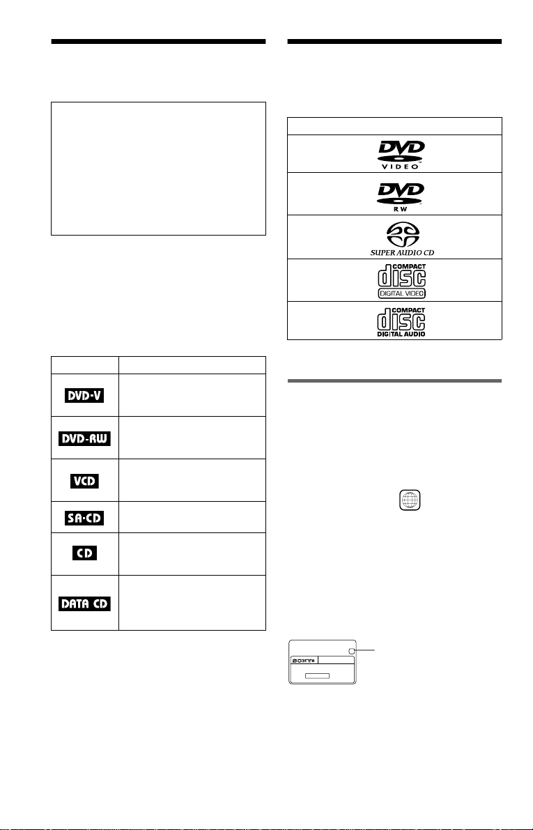
• The meanings of the icons used in this
manual are described below:
Icon Meaning
Functions available for DVD
VIDEOs or DVD-Rs/DVDRWs in video mode
Functions available for DVDRWs in VR (Video Recording)
mode
Functions available for VIDEO
CDs or CD-Rs/CD-RWs in
video CD for mat
Functions available for Super
Audio CDs
Functions available for music
CDs or CD-Rs/CD-RWs in
music CD format
Functions available for DATA
CDs (CD-ROMs/CD-Rs/CDRWs containing MP3* audio
tracks)
* MP3 (MPEG 1 Audio Layer 3) is a standard
format defined by ISO/MPEG which compresses
audio data.
Format of discs
DVD VIDEO
(page 87)
DVD-RW
(page 87)
Super Audio CD
(page 88)
VIDEO CD
Music CD
“DVD VIDEO” and “DVD-RW” are
trademarks.
Region code
Your player has a region code printed on th e
back of the unit and only will play DVD
VIDEO discs (p la yback only) labelled w i th
identical region codes. This system is used to
protect copyrights.
DVD VIDEOs labelled will also play on
this player.
If you try to play any other DVD VIDEO, the
message “Playback prohibited by area
limitations.” will appear on the TV screen.
Depending on the DVD VIDEO, no region
code indication may be labelled even though
playing the DVD VIDEO is prohibited by
area restrictions.
X
DVP–XXXX
00V 00Hz
NO.
00W
0-000-000-00
ALL
Region code
6
Example of discs that the player
cannot play
The player cannot play the following dis cs :
• All CD-ROMs (including PHOTO CDs)/
CD-Rs/CD-RWs other than those recorded
in the following formats:
–music CD format
–video CD format
–MP3 format that conforms to ISO9660*
Level 1/Level 2, or its ext ended format,
Joliet
• D ata part of CD-Extras
• DVD-ROMs
• DVD Audio discs
* A logical form at of file s a nd f olde r s on CD-
ROMs defined by ISO (International St an da rd
Organization)
Also, the player cannot play the fo llowing
discs:
• A DVD VIDEO with a different region
code.
• A disc that has a non-standard sha p e (e.g.,
card, heart).
• A disc with paper or stickers on it.
• A disc that has the adhesive of cellophane
tape or a sticker still left on it.
some playback features may not be available.
Also, refer to the instructions supplied with
the DVDs or VIDEO CDs.
Copyrights
This product incorporates copyrigh t
protection techn ol ogy that is protected by
method claims of certain U.S. patents, ot her
intellectual property rights owned by
Macrovision Co rporation, and other r ig ht s
owners. Use of th i s copyright protection
technology must be authorized by
Macrovision Corporati on, and is intend ed for
home and other limited viewing uses only
unless otherwise authorized by Macrovision
Corporation. Rever se engineering or
disassembly is prohibited.
Notes About the D i scs
• To keep the disc clean, handle the disc by its
edge. Do not touch t he surface.
Note
Some DVD-Rs, DVD-RWs, CD-Rs, or CD-RWs
cannot be played o n this player due to the record ing
quality or physical condition of the disc, or the
characteristics of the recording device.
The disc will not play if it ha s not been correctly
finalized. Also, images in DVD-RW discs with
CPRM* protection may not be played if the y
contain a c opy protection si gnal. “Copyright lock”
appears on the screen. For more information, see the
operating instructions for the recording device.
Note that discs created in the Packet Write format
cannot be played.
* CPRM (Content Protection for Recordable
Media) is a coding technology t ha t pr otects the
copyright of images.
Note on playback operations of
DVDs and VIDEO CDs
Some playback operations of DVDs and
VIDEO CDs may be intent i onally set by
software producers. Since this player plays
DVDs and VIDEO CDs according to the disc
contents the software producer s designed,
• Do not expose the disc to direct s un l i ght or
heat sources such as hot air ducts, or leave it
in a car parked in direct sunlight as the
temperature may rise considerably inside
the car.
• After playing, store the disc in it s case.
• Cl ean the disc with a cleaning cl oth.
Wipe the disc fr om the centre out.
• Do not use solvents such as benz i n e,
thinner, commercially available cleaners , or
anti-static spra y in te nded for vinyl LPs.
7
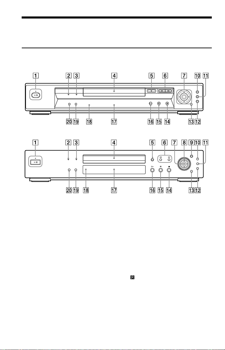
Index to Parts an d Controls
For more information, refer to the pages indicated in parentheses.
Front panel
DVP-NS705V
DVP-NS905V
A [/1 (on/standby) button/indicator (33)
Lights up in green wh en t he power is on
and lights up in red when the p la yer is in
standby mode.
B SUPER AUDIO CD indicator
Lights up when playing a Super Audio
CD.
C MULTI CHANNEL indicator
Lights up when:
–playing a disc that contains multiple
audio signal channels
–the disc is not inserted
D Disc tray (33)
E A (open/close) butt on ( 33)
F ./> (previ ous/ next ) but tons ( 34)
G C/X/x/c ENTER buttons (38)
8
H Click shuttle (36)
(DVP-NS905V only)
I JOG button/indicator (37)
(DVP-NS905V only)
J TOP MENU button (38)
K MENU button (38) (42)
L O RETURN button (34)
M DISPLAY button ( 13 )
N x (stop) button (34)
O X (pause) button (34)
P H (play) button (33)
Q Front panel display ( 9)
R (remote sensor) (16)
S SURROUND button (58)
T PICTURE MODE button (63)
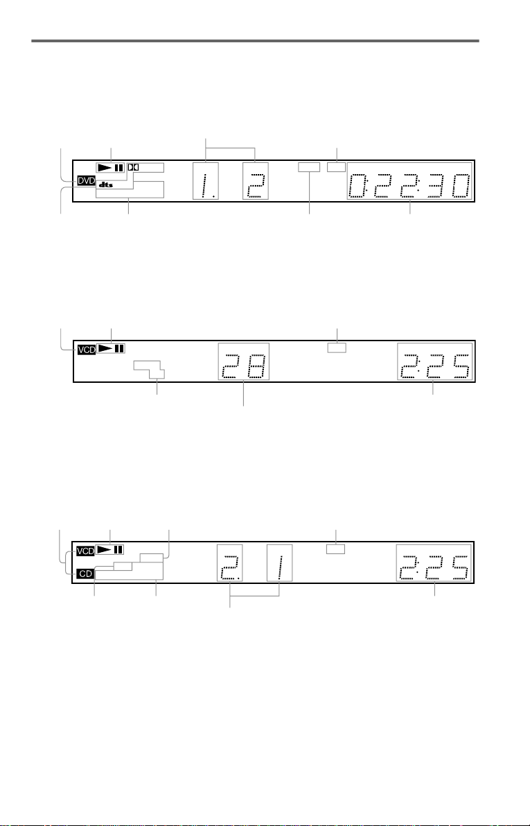
Front panel display
When playing back a DVD VIDEO/DVD-RW
Disc type
Current audio
signal (56)
Playing status
Digital
MULTI
REPEAT 1
SHUFFLE PGM A–B
Current play
mode (44)
Current title and chapt er (53)
TITLE TRACK CHAP INDEX ANGLE NTSC HOUR
Lights up when you can
change the angle (61)
Lights up when the player outputs
the signal in NTSC format
MIN SEC
Playing time (53)
When playing back a VIDEO CD with Playback Control (PBC) (41)
Disc type
Playing status
Digital
MULTI
REPEAT 1MPEG
SHUFFLE PGM A–B
Current play mode (44)
Lights up when the player outputs the signal in NTSC format
TITLE TRACK CHAP INDEX ANGLE NTSC HOUR
MIN SEC
Playing time (53)
Current scene (53)
When playing back a Super Audio CD, C D, DATA CD (MP3 audio), or VIDEO CD (without
PBC)
Disc type*
Playing status
Lights up when playing the multichannel playback area on Super
Audio CDs (40)
Lights up when the player ou tputs
the signal in NTSC format
SHUFFLE PGM A–B
Lights up when
playing MP3
Digital
REPEAT 1
MP3
Current play
mode (44)
MULTI
TITLE TRACK CHAP INDEX ANGLE NTSC HOUR
Current track and index (53 )
audio tracks (42)
* When playing the HD lay er of Super Audio CD
discs, the disc type is not displayed.
z Hint
You can turn off the front panel display by setting
“DIMMER” in “CUSTOM SETUP” to “OFF” in
the Setup Display (page 77).
MIN SEC
Playing time (53)
,continued
9
Rear panel
DVP-NS705V
L
R
OPTICAL
COAXIAL
PCM/DTS/MPEG/
DOLBY DIGITAL
DIGITAL OUT
DVP-NS905V
L
R
COAXIAL
OPTICAL
PCM/DTS/MPEG/
DOLBY DIGITAL
DIGITAL OUT
FRONT REAR
5.1CH OUTPUT
FRONT REAR
5.1CH OUTPUT
WOOFER
WOOFER
CENTER
CENTER
AUDIO
LINE OUT
AUDIO
LINE OUT
S VIDEO OUT
VIDEO
LR
LINE (RGB)-TV
S VIDEO OUT
VIDEO
LR
LINE 1 (RGB)-TV
LINE 2
A DIGITAL OUT (COAXIAL) jack (25)
(26) (27)
B DIGITAL OUT (OPTICAL) jack (25)
(26) (27)
C 5.1CH OUTPUT jacks (27)
D LINE OUT L/R (AUDIO) jacks (24)
(25) (26)
10
E LINE OUT (VIDEO) jack (19)
F S VIDEO OUT jack (19)
G LINE 2 jack (17) (19)
(DVP-NS905V only)
H LINE (RGB)-TV jack (17) (19)
(for DVP-NS705V)
LINE 1 (RGB)-TV jack (17) (19)
(for DVP-NS905V)
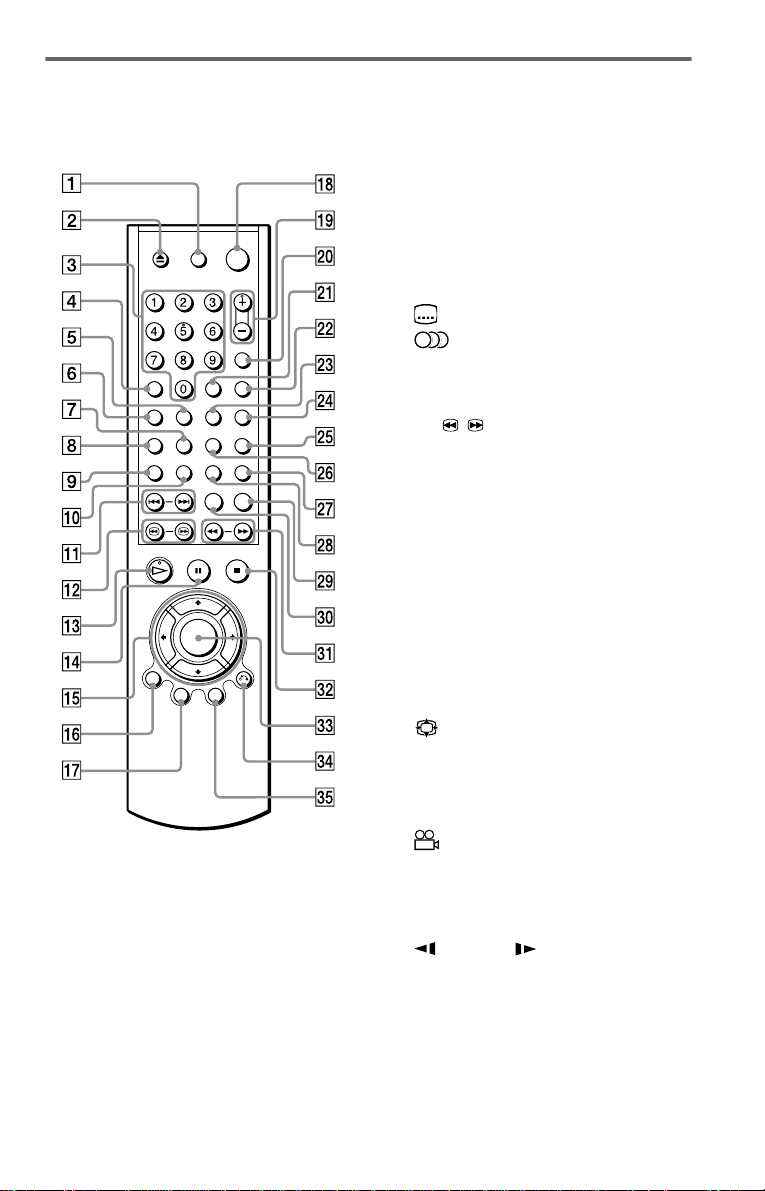
Remote
DVP-NS705V A TV [/1 (on/standby) button (71)
Z (open/close) button (34)
B
C Number buttons (38)
The number 5 butt on has a tactile dot.*
D CLEAR button (44)
E SACD (Super Audio CD)/CD button
(40)
F SACD (Super Audio CD) MULTI/
2CH button (40)
G (subtitle) button (61)
H (audio) button (56)
I TIME/TEXT button (52)
J REPEAT button (46)
K ./> (previous/next) buttons (34)
L c / C (search/step) buttons
(35)
M H (play) button (33)
The H button has a tactile dot.*
N X (pause) button (34)
O C/X/x/c buttons (38)
P DISPLAY button (13)
Q TOP MENU button (38)
R [/1 (on/standby) button (33)
S 2 (volume) +/– buttons (71)
The + button has a tactile dot.*
T t (TV/video) button (71)
U ENTER button (performs the same
function as ed)
V (wide mode) button (71)
W SHUFFLE button (46)
X TV/DVD button (71)
Y PICTURE NAVI (navigation) button
(50)
Z (angle) button (61)
wj PICTURE MODE button (63)
wk SUR (surround) button (58)
wl REPLAY button (34)
e; SEARCH MODE button (49)
ea m/M (scan/slow) buttons
(35)
es x (stop) button (34)
ed ENTER button (29)
ef O RETURN button (34)
eg MENU button (38) (42)
* Use the tactile dot as a reference when operating
the player.
,continued
11
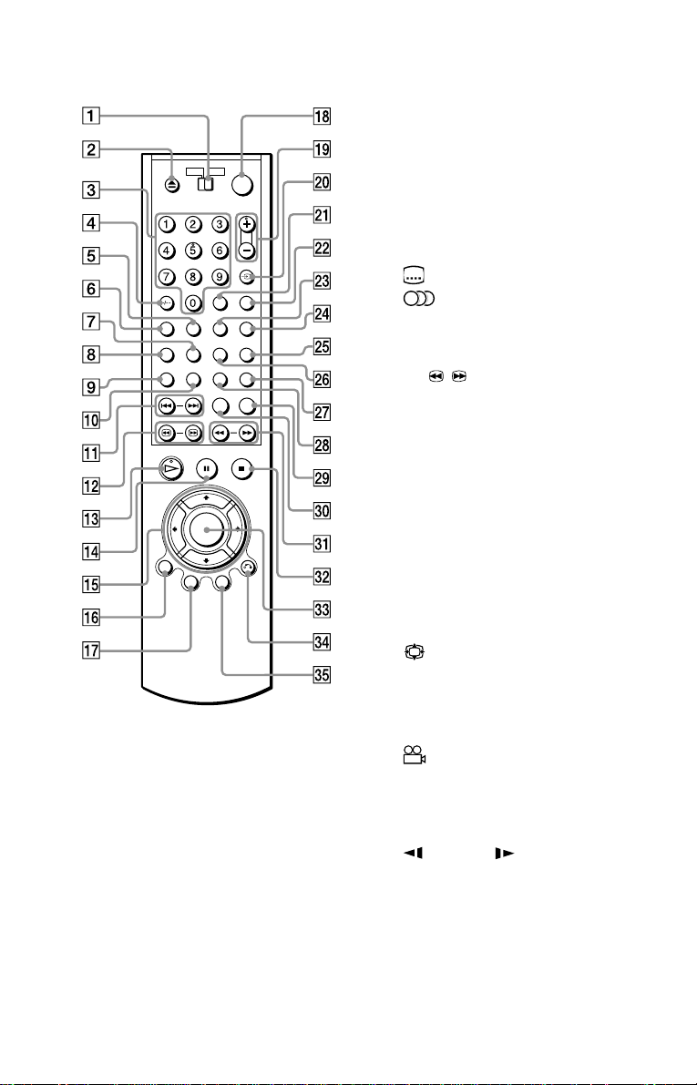
DVP-NS905V
A TV/DVD switch (71)
Z (open/close) butto n ( 34 )
B
C Number buttons (38)
The number 5 butt on has a tactile dot.*
D CLEAR /- (ten’s digit) button (44)
(71)
E SACD (Super Audio CD)/CD button
(40)
F SACD (Super Audio CD) MULTI/
2CH button (40)
G (subtitle) button (61)
H (audio) button (56)
I TIME/TEXT button (52)
J REPEAT button (46)
K ./> (previous/next) buttons (34)
L c / C (search/step) buttons
(35)
M H (play) button (33)
The H button has a t actile dot.*
N X (pause) button (34)
O C/X/x/c buttons (38)
P DISPLAY button ( 13 )
Q TOP MENU button (38)
R [/1 (on/standby) button (33)
S 2 (volume) +/– buttons (71)
The + button has a t actile dot.*
T TV/DVD/t (TV/video) button (71)
U ENTER button (performs the same
function as ed)
V (wide mode) button (71)
W SHUFFLE button (46)
X A-B button (47)
Y PICTURE NAVI (navigation) button
(50)
Z (angle) button (61)
wj PICTURE MODE button (63)
wk SUR (surround) button (58)
wl REPLAY button (34 )
e; SEARCH MODE button (49)
ea m/M (scan/slow) buttons
(35)
es x (stop) button (3 4)
ed ENTER button (29)
ef O RETURN button (34)
eg MENU button (38) (42)
12
* Use the tactile dot as a reference when operatin g
the player.
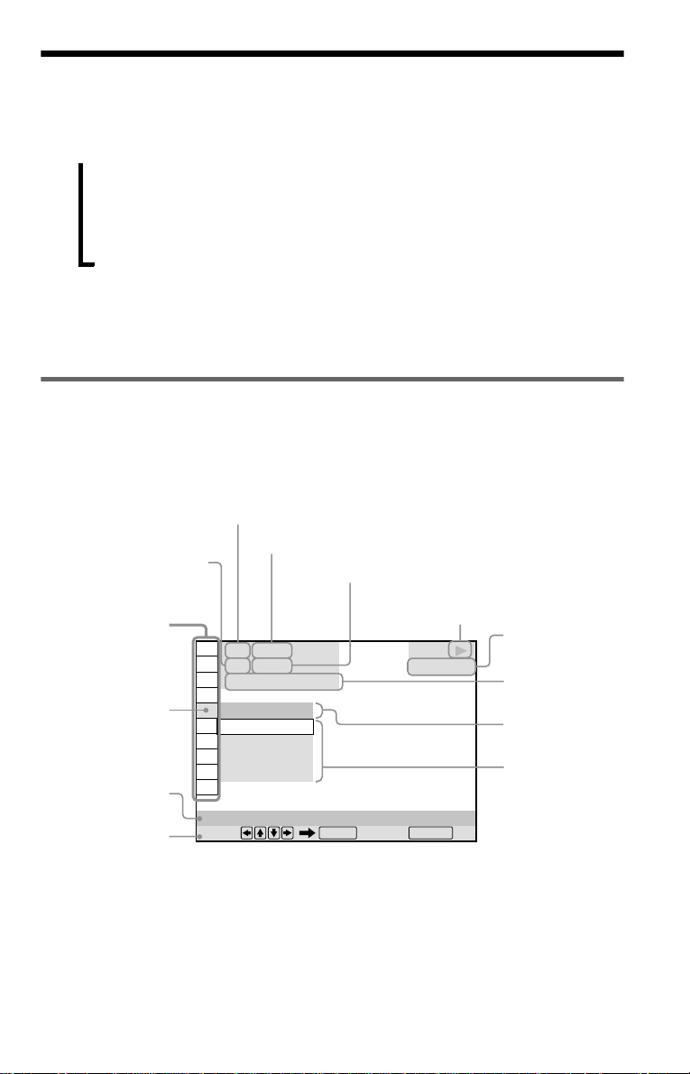
Guide to the Control Menu Display (Magic Pad)
Use the Control Menu to select a function and to view related information. Press DISPLAY
repeatedly to turn on or change the Contro l M enu display as follows:
Control Menu display 1
,
z Hint
You can skip the ADVANCED display by setting
“OFF” under “ADVANCED” in the Control Menu
(page 54).
Control Menu Display
The Control Menu display 1 and 2 will show di fferent items depend ing on the disc type. For
details about each item, please refer to the page s in parentheses.
Example: Control Menu display 1 when playing a DVD VIDEO.
Currently playing chapter
number
Control Menu
items
Select ed item
Function nam e of
selected Control
Menu item
Operation message
m
Control Menu display 2 (DVD/VIDEO CD only)
m
ADVANCED display (DVD only. See page 54.)
m
Control Menu display off
Currently playing title number*
Total number of titles*
**
1 2 ( 2 7
1 8 ( 3 4
T
1 : 3 2 : 5 5
Total number of chapters**
)
)
OFF
OFF
1: ENGLISH
2: FRENCH
3: SPANISH
SUBTITLE
Select: Cancel:
ENTER RETURN
Playback status
(N Playback, X Pause, x Stop, etc .)
Type of disc
being played
DVD VIDEO
Playing time
Current setting
Options
* Displays the scene number for VIDEO CDs
(PBC is on), track number for VIDEO CDs/
Super Audio CDs/CDs, album number for
DATA CDs.
** Displays the index number for VIDEO CDs/
Super Audio CDs/CDs, MP3 audio track
number for DATA CDs.
,continued
13
List of Control Menu items
Item Item Name, Function, Relevant Disc Type
TITLE (page 49)/SCENE (page 49)/TRACK (page 49)
Selects the title, scene, or track to be played.
CHAPTER (page 49)/INDEX (page 49)
Selects the chapter or index to be played.
ALBUM (page 42)
Selects the album to be played.
TRACK (page 49)
Selects the track to be pl ayed.
INDEX (page 49)
Selects the index to be played.
ORIGINAL/PLAY LIST (page 39)
Selects the type of title s (DVD-RW) to be p layed, the ORIGINAL on e, or a n edite d
PLAY LIST.
TIME/TEXT (page 49)
Checks the elapsed time and the remaining playback time.
Input the time code for picture and music searching.
Displays the DVD/Super Audio CD/CD text or the DATA CD’s track name.
MULTI/2CH (page 40)
Selects the playback area on Super Audio CDs when available.
AUDIO (page 56)
Changes the audio setting.
SUBTITLE (page 61)
Displays the subtitles.
Changes the subtitle l anguage.
ANGLE (page 61)
Changes the an gl e.
SURROUND (page 58)
Selects the surro und functions.
ADVANCED (page 54)
Displays the information (bit rate or layer) of the disc currently playing.
PARENTAL CONTROL (page 66)
Set to prohibit playba ck on this player.
14
SETUP (page 74)
QUICK Setup (page 29)
Use Quick Se tup t o ch oose t he de sire d lan guage of t he on-s cree n di spla y, th e aspe ct
ratio of the TV, the audio output signal, and the size of the speakers you are
connecting.
CUSTOM Setup
In addition to the Quick Setup setting, you can adjust various other settings.
RESET
Returns the settings in “SETUP ” to the default setting.
PROGRAM (page 44)
Selects the title, chapter, or track to play in the order you want.
SHUFFLE (page 46)
Plays the title, ch apt er, or track in rando m order.
REPEAT (page 46)
Plays the entire disc (all titles/all tracks/all albums) repeatedly or one title/chapter/
track/album repeatedly.
A-B REPEAT (page 47)
Specifies the parts you want to play repeatedly.
BNR (page 62)
Adjusts the picture quality by reducing the “block noise” or mosaic like patterns that
appear on your TV scr ee n.
CUSTOM PICTURE MODE (page 63)
Adjusts the video signal from the player. You can select the picture quality that best
suits the programme you are watching.
DIGITAL VIDEO ENHANCER (page 65)
Exaggerates the outline of the image to produce a sharper picture.
PICTURE NAVIGATION (page 50)
Divides the scre en into 9 subscreens to help you find the scene you want quickl y.
z Hint
The Control Menu icon indicator lights up in green
t
except “OFF.” (“SURROUND,” “PROGRAM,”
“SHUFFLE,” “REPEAT,” “A-B REPEAT,”
“BNR,” “DIGITAL VIDEO ENHANCER” only).
The “ANGLE” indicator lights up in gree n only
when the angles can be changed. The “CUSTOM
PICTURE MODE” indicator lights up in green
when any setting other than “STANDARD” is
selected.
when you select any item
15

Simple Start Guide
Quick Overview
Step 2: Inserting Batteries Into the Remote
A quick overview presented in this guide will
give you enough information to start using the
player for your enj o yment. To use the
surround sound features of this player, refer
to “Hookups” on page 19.
Notes
• You cannot connec t this player to a TV that does
not have a SCART (EURO AV) or video input
jack.
• Be sure to disconnect the mains lead of each
component before connecting.
Step 1: Unpacking
Check that you have the following items:
• Audio/video cord (pinplug × 3 y pinplug
× 3) (1)
• Remote commander (remote) (1)
• R 6 (si ze AA) batte ries (2)
You can control the player using the supplied
remote. Insert two R6 (size AA) batteries by
matching the 3 and # ends on the batteries
to the markings inside the compartment.
When using the remote, poin t it at the r emote
sensor on the player.
Notes
• Do not leave the remote in an extremely hot or
humid place.
• Do not drop any foreign object into the remote
casing, particularly when replacing the batteries.
• Do not expose the remote sensor to direct light
from the sun or a lighting apparatus. Doing so
may cause a malfunction.
• If you do not use the remote for an extended
period of time, remove the batteries to avoid
possible damage from battery le ak ag e and
corrosion.
16
Step 3: TV Hookups
Connect a SCART (EURO AV) cord (not supplied) and mains lead in the or der (1~3) shown
below. Be sure to connect the mains lead last.
CD/DVD Player
L
R
COAXIAL
OPTICAL
FRONT REAR
WOOFER
PCM/DTS/MPEG/
DOLBY DIGITAL
DIGITAL OUT
5.1CH OUTPUT
LINE 1 (RGB)-TV
CENTER
AUDIO
LINE OUT
S VIDEO OUT
VIDEO
LR
LINE 1 (RGB)-TV
LINE 2
3 mains lead
Simple Start Guide
LINE 1 (RGB)-TV
to T LINE 1
(RGB)-TV
to SCART (EURO AV) input
TV
*
1 SCART (EURO AV)
cord (not supplied)
2 mains lead
l : Signal flow
* Connect to T LINE (RGB)-TV for DVP-
NS705V.
When connecti ng to a stan dard 4: 3 scre en
TV
Depending on the disc, the image may not fit
your TV screen. If you want to change the
aspect ratio, re fer to page 76.
If your TV does not have a SCART (EURO
AV) connection
Refer to B in “Step 1: Connecting the Video
Cords” on page 19.
LINE 2
to t LINE 2
(DVP-NS905V only)
to SCART
(EURO AV) output
VCR
Note
Be sure to connect your TV to the SCART (EURO
AV) cord to the LINE 1 (RGB)-TV jack on the
player. (DVP-NS905V only)
If you are connecting to a VCR
(DVP-NS905V only)
Connect your VCR to the LINE 2 jack on th e
player. The VCR can record the signal only
from your TV.
17

Step 4: Playing a Disc
With the playback side facing down
A Turn on the TV.
B Press [/1 on the player.
C Switch the input se lector on your
TV so that the signal from the
player appears on the TV screen.
D Press A on the player to open the
disc tray.
E Place the disc on the tray with the
playback side facing down.
F Press H.
The disc tray closes and the player begins
playing the disc.
After step 6
Depending on the di sc, a menu may be
displayed on the TV screen. If so, select the
item you want from th e m enu and play the
DVD VIDEO (page 38) or VIDEO CD disc
(page 41).
To stop playin g
Press x.
To remove the disc
Press A.
To turn off the player
Press [/1. The player enters standby m ode
and the power indicator lights up in red.
18
Hookups
Hooking Up the Player
Follow steps 1 to 4 to hook up and adjust the settings of the player.
Before you start, disconnect the mains leads, check that you have all of the supplied accessories,
and insert the batteries into the remote (page 16).
Notes
• Plug cor ds se c ur el y to pr e ven t unwa nte d noise.
• Refer to the instructions supplied with the components to be connected.
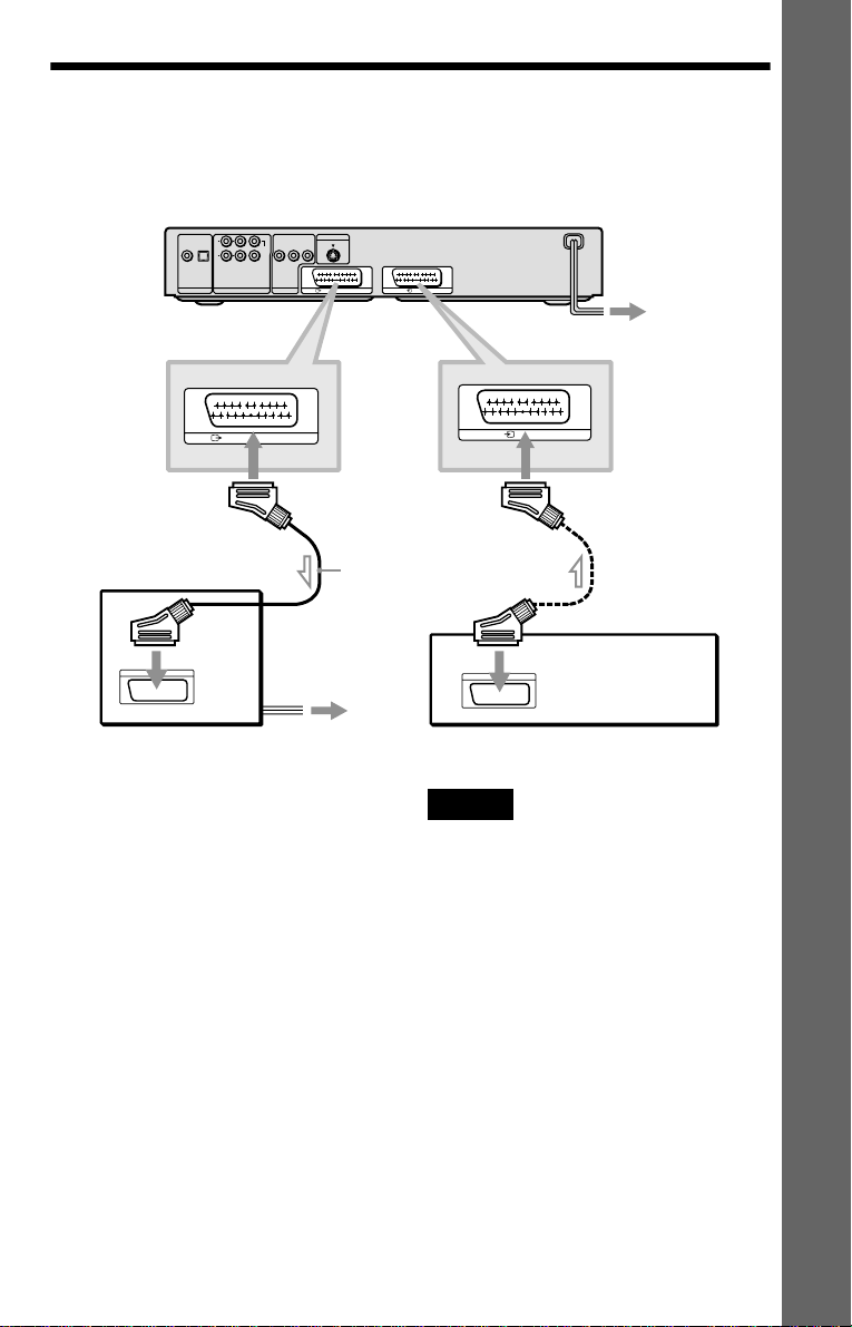
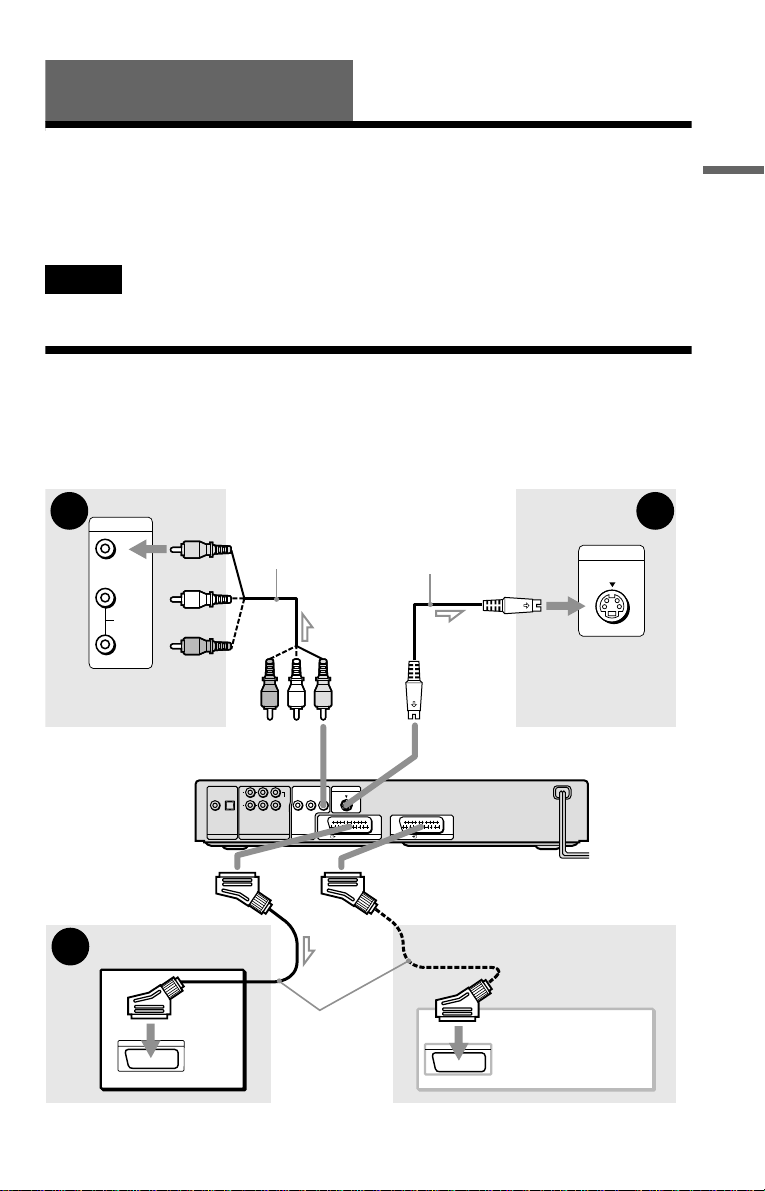
Step 1: Connecting the Video Cords
Connect th is player to your TV moni tor, pr ojector, or AV ampl ifier ( receive r) using a video cord.
Select one of the patter ns A through C, according to the inp ut jack on yo ur TV moni tor,
projector, or AV amplifier (receiver).
B C
INPUT
TV, projector or AV
amplifier (receiver)
(yellow)
VIDEO
L
AUDIO
R
to LINE OUT (VIDEO )
to T LINE 1
(RGB)-TV*
Audio/video cord
(supplied)
L
R
COAXIAL
OPTICAL
FRONT REAR
WOOFER
PCM/DTS/MPEG/
DOLBY DIGITAL
DIGITAL OUT
5.1CH OUTPUT
CENTER
AUDIO
LINE OUT
VIDEO
LR
S VIDEO cord
(not supplied)
(yellow)
S VIDEO OUT
LINE 1 (RGB)-TV
to t LINE 2
(DVP-NS905V only)
INPUT
S VIDEO
TV, projecto r or AV
amplifier (receiver)
to S VIDEO OUT
CD/DVD player
LINE 2
Hookups
A
TV
SCART
(EURO AV)
cord (not
supplied)
l : Signal flow
* Connect to T LINE (RGB)-TV for DVP-NS705V.
connecting the VCR
,continued
VCR
19
A If you are connecting to a SCART (EURO AV) input jack
Connect the SCAR T (EUR O AV) cord (n ot supplied). Be sure to make the c onnections f irmly to
avoid hum and noise. When you connect using the SCART (EURO AV) cord, check that the TV
conforms to S video or RGB signals. Refer to the operating instructions supplied with the TV to
be connected. Also, when you se t “LINE” to “S VIDEO” or “RGB” under “SCREEN SETUP”
in the Setup Displa y (page 76), use a SCART (EURO AV) cor d th at conforms to each signal.
If you are connecting to a VCR (DVP-NS905V only)
Connect your VCR to the LINE 2 jack on the player. The VCR can record the signal only from
your TV.
B If you are connecting to a video input jack
Connect the yellow plug of the audio/v ideo cord (supplied) to the yellow (video) jacks. You will
enjoy standard quality images.
Yellow (Video)
White (L)
Red (R)
Yellow (Video)
White (L)
Red (R)
Use the red and whit e plugs to connect to the audio input jacks ( page 24). (Do this if you are
connecting to a TV only.)
C If you are connecting to an S VIDEO input jack
Connect an S VIDEO cord (not supplied). You will enjoy high quality images.
Notes
• Do not con ne ct a VCR, etc. between your TV and the player. If you pass the player signals via the VCR,
you may not receive a clear image on the TV screen. If you r TV has only one audio/video input jack,
connect the player to this jack.
VCR
CD/DVD player
Connect
directly
• When you c onne c t the pla ye r to your TV via the SCART (EURO AV) jacks, the TV’s input source is set
to the player automatically when you start playback or press any button except for \/1. In this case, press
TV/DVD on the remote to return the input to the TV.
TV
When you play a disc recorded in the NTSC colour system, the player outputs the video
signal or the Setup Display etc. in the NTSC colour system and the picture may not appear
on the PAL colour system television s. In th is ca se, open the tray and remove the disc.
20

For DVP-NS905V
• If you cannot view the pictures from a VCR through this player whic h is conne c te d to a TV with RGB
component jacks, set to t (Audio/Video) on your TV. When you selec t (RGB), the TV
cannot receive the signal from the VCR.
• If you want to use your VCR’s SmartLink function, connect the VCR to your TV’s SmartLink jack and
connect the player to the TV with anot he r jack .
• The Sma rtLink function may not work properly if your VCR is connec ted to your TV via the SCART
(EURO AV) jacks on the player.
Hookups
21
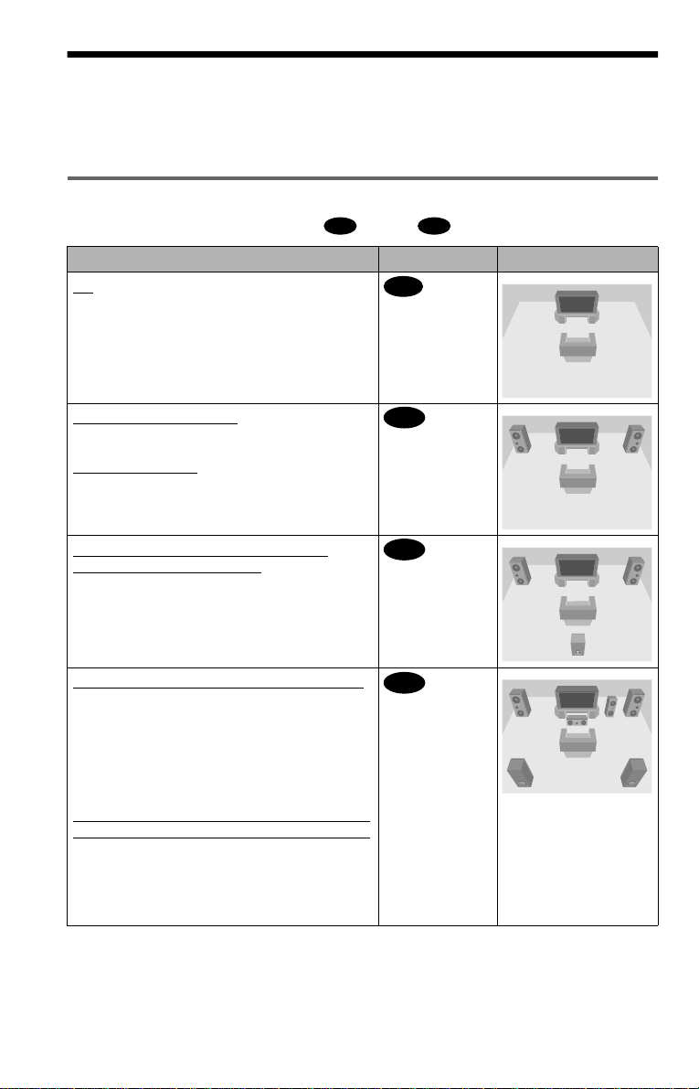
Step 2: Connecting the Audio Cords
Refer to the chart below to se lect the c onnection that best sui ts your syst em. Be sure to also read
the instructions for the components you wish to connect.
Select a connection
Select one of the foll owing connections, through .
Components to be connected Connection Your setup (example)
TV
• Surround effects: TVS DYNAMIC (page 58),
TVS WIDE (page 58)
A D
A
(page 24)
Stereo amplifier (receiver)
• Surround effects: TVS STANDARD (page 59)
or
MD deck/DAT deck
• Surround effects: TVS STANDARD (page 59)
AV amplifier (receiver) having a Dolby
Surround (Pro Logic) decoder and 3 to 6
speakers
• Surround ef fects: Dolby Surround (Pro Logic)
(page 87)
AV amplifier (receiver) with 5.1 ch input jacks
and 4 to 6 speakers
• Surround ef fects:
– Dolby Digital (5.1 ch) (page 87)
– DTS (5.1 ch) (DVP-NS905V only) (page 87)
– Super Audio CD Mul t i ch annel (page 88)
– MPEG audio (5.1 ch) (page 87)
and two speakers
*
or
AV amplifier (receiver) with digital input jacks
having a Dolby, DTS**, or MPEG audio decoder
and 6 speakers
• Surround ef fects:
– Dolby Digital (5.1 ch) (page 87)
– DTS (5.1 ch) (page 87)
– MPEG audio (5.1 ch) (page 87)
(page 25)
B
(page 26)
C
D
(page 27)
22

z Hint
If you connect an AV amplifier (receiver) that
conforms to the 96 kHz sampling frequency, use
connection .
* Manufactured under license fro m Dolby
Laboratories.
“Dolby”, “Pro Logic”, and the double-D symbol
are trademarks of Dolby Laboratories.
For DVP-NS705V
** “DTS” and “DTS Digital Out” are trademarks
of Digital Theater Systems, Inc.
For DVP-NS905V
** Man u fac tured under license from Digital
Theater Systems, Inc. US Pat. No. 5,451,942,
5,956,674, 5,974,380, 5,978,762 and other
world-wi de pa te nts is su e d an d pe nd i ng. “DTS”
and “DTS Digital Surround” a re registere d
trademarks of Digital Theater Systems, Inc.
Copyright 1996, 2000 Digital Theater Systems,
Inc. All rights reserved.
D
Hookups
23
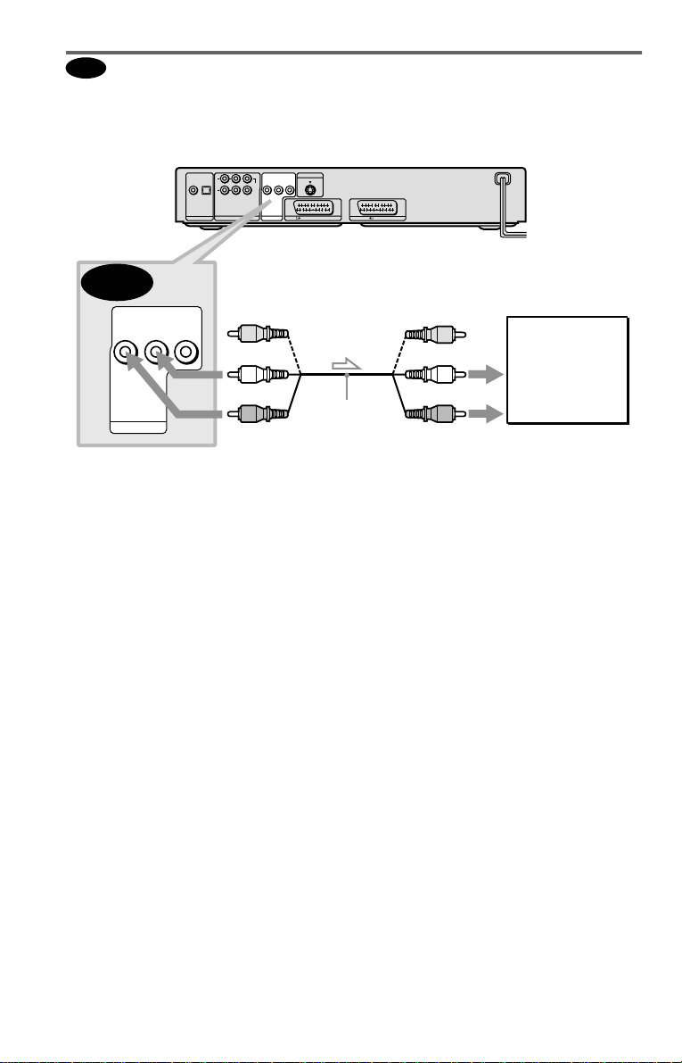
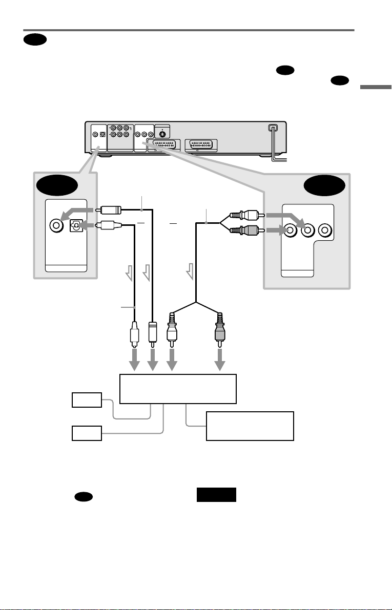
A
Connecting to your TV
This connection will use your TV speakers for sound. If you use the SCART (EURO AV) cord
in
A of “Step 1: Connecting the Video Cords” (page 19), you do not have to co nnect audio
cords to your TV .
CD/DVD player
L
R
COAXIAL
OPTICAL
FRONT REAR
WOOFER
PCM/DTS/MPEG/
DOLBY DIGITAL
DIGITAL OUT
5.1CH OUTPUT
CENTER
AUDIO
LINE OUT
S VIDEO OUT
VIDEO
LR
LINE 1 (RGB)-TV
LINE 2
A
AUDIO
VIDEO
LR
LINE OUT
to LINE OUT L/R (AUDIO)
l : Signal flow
* The yellow plug is used for video signals (page
19).
z Hint
When connecting to a monaural TV, use a stereomono conversion cord (not supplied). Connect the
LINE OUT L/R (AUDIO) jacks to the TV’s audio
input jack.
(yellow)*
(white)
(red)
Audio/video
cord (supplied)
(yellow)
(white)
(red)
to audio input
TV
24
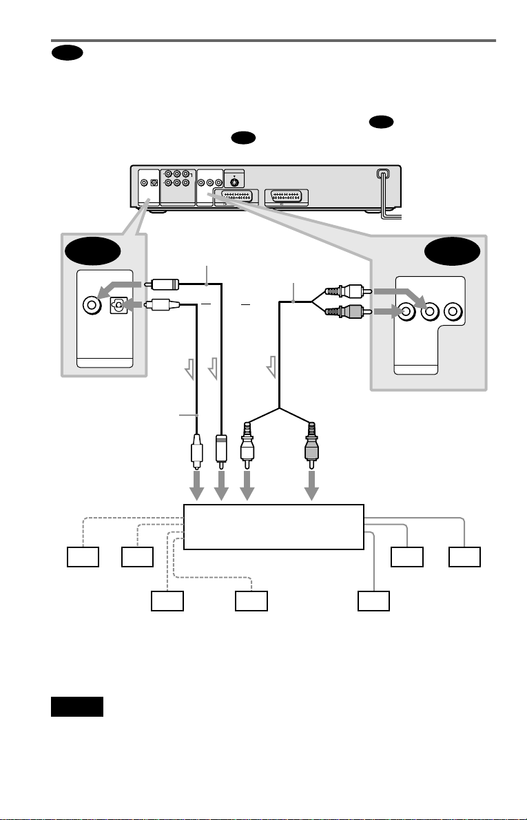
Connecting to a stereo amplifier (r eceiver) and 2 speakers/ Connecting to
B
an MD deck or DAT deck
If the stereo amplifie r ( re ce iv er ) h a s audio input jacks L and R only, use . If the amplifier
(receiver) has a digital input jack, or when connecting to an MD deck or DAT deck, use .
In this case, you can also connect the player directly to the MD deck or DAT deck without using
your stereo amplifier (re ceiver).
CD/DVD player
L
R
COAXIAL
OPTICAL
FRONT REAR
WOOFER
PCM/DTS/MPEG/
DOLBY DIGITAL
DIGITAL OUT
5.1CH OUTPUT
CENTER
LINE OUT
S VIDEO OUT
AUDIO
VIDEO
LR
LINE 1 (RGB)-TV
LINE 2
B-1
B-2
Hookups
B-2
COAXIAL
OPTICAL
PCM/DTS/MPEG/
DOLBY DIGITAL
DIGITAL OUT
to DIGITAL OUT
(COAXIAL or OPTICAL)
Optical digital cord
(not supplied)
Remove jack cap
before connecting
digital input
[Speakers]
Front (L)
Front (R)
l: Signal flow
Coaxial digital
cord (not supplied)
or
Stereo amplifier (receiver)
Stereo audio cord
(not supplied)
or
(white)
(red)
to LINE OUT L/R (AUDIO)
(red)(white)
to audio inputto coaxial or optical
MD deck/DAT deck
AUDIO
LR
LINE OUT
B-1
VIDEO
z Hints
B-1
• In connection
, you can use the supplied
audio/video cord instead of using a separate stereo
audio cord.
• To real iz e better surround sound effects, make
sure that your listening position is in between
your speakers.
Note
Super Audio CD audio signals are not output from
the digital jack .
,continued
25
C
Connecting to an AV amplifier (receiver) having a Dolby Surround (Pro
Logic) decoder and 3 to 6 speakers
You can enjoy the Dol by Surround effects onl y w hen playing Dolby Surround audio or multichannel audio (Dolby Digital) discs.
If your amplifier (receiver) has L and R aud i o input jacks only, use . If your amplifier
(receiver) has a digital input jack, us e .
CD/DVD player
L
CENTER
R
OPTICAL
COAXIAL
FRONT REAR
WOOFER
PCM/DTS/MPEG/
DOLBY DIGITAL
DIGITAL OUT
5.1CH OUTPUT
AUDIO
LINE OUT
C-2
S VIDEO OUT
VIDEO
LR
LINE 1 (RGB)-TV
LINE 2
C-1
C-2
OPTICAL
COAXIAL
PCM/DTS/MPEG/
DOLBY DIGITAL
DIGITAL OUT
to DIGITAL OUT
(COAXIAL or OPTICAL)
Optical digital cord
(not supplied)
Remove jack cap
before connecting
to coaxial or optical digital
input
[Speakers]
Rear (L)
l: Signal flow
Rear (R)
Subwoofer
Coaxial digital cord
(not supplied)
or
or
Amplifier (receiver) with Dolby
Surround decoder
Centre
Stereo
audio cord (not
supplied)
(red)(white)
to audio input
(white)
AUDIO
(red)
LINE OUT
to LINE OUT L/R (AUDIO)
[Speakers]
Front (L)
Rear (mono)
C-1
VIDEO
LR
Front (R)
z Hint
For correct speaker location, refer to the ope rat ing
instructions of the amplifier (receiver).
Notes
• When connecting 6 speakers, replace the
monaural rear speaker with a centre speaker, 2
rear speakers and a subwoofer.
• Super Audio CD audio signals are not output from
the digital jack.
26
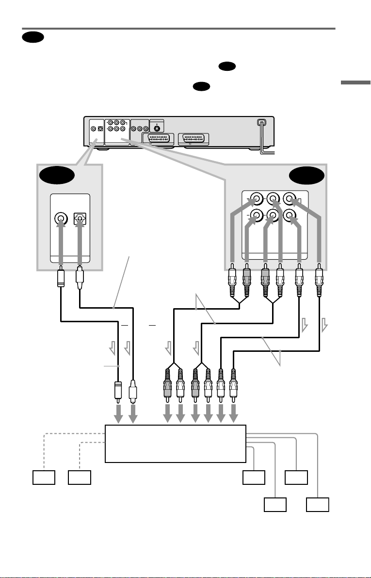
D
Connecting t o an AV amplifier (receiver) with 5.1 ch inpu t ja cks and /or a
digital input jack and 4 to 6 speakers
D-2
D-1
L
R
FRONT REAR
5.1CH OUTPUT
D-1
CENTER
WOOFER
If your AV amplif i er (receiver) has 5. 1 channel inputs, use .
If you want to use the Dolby Digital, MPEG audio, or DTS decoder function on your AV
amplifier (receiver), connect to its di gital jack usin g . With the following connectio ns, you
can enjoy a more rea li s ti c audio presence in the comfort of your own ho m e.
D-2
COAXIAL
PCM/DTS/MPEG/
DOLBY DIGITAL
DIGITAL OUT
CD/DVD player
COAXIAL
OPTICAL
PCM/DTS/MPEG/
DOLBY DIGITAL
DIGITAL OUT
OPTICAL
L
R
FRONT REAR
WOOFER
5.1CH OUTPUT
to DIGITAL OUT
(COAXIAL or OPTICAL)
Optical digital cord
(not supplied)
Remove jack cap
before connecting
CENTER
LINE OUT
S VIDEO OUT
AUDIO
VIDEO
LR
LINE 1 (RGB)-TV
LINE 2
to 5.1CH
OUTPUT
Stereo audio cord
(not supplied)
Hookups
Coaxial digital cord
(not supplied)
to coaxial or optical
digital input
[Speakers]
Centre
Subwoofer
l: Signal flow
or
or
AV amplifier (receiver) having
5.1ch inputs or/and a decoder
Monaural audio cord
(not supplied)
to audio input
[Speakers]
Front (L)
Front (R)
Rear (L)
Rear (R)
,continued
27

: Connecting to the 5.1ch input jacks
D-1
You can enjoy 5.1c h surround sound using
the internal Dolby Digital, MPEG audio, DTS
(DVP-NS905V onl y), or Super Audio CD
Multi decoder of this player. (When 6
speakers are connected, set “SURROUND”
to “OFF.”)
You can also enjoy Dolby Surround (Pro
Logic) sounds, or surround sounds using
various “SURROUND” modes (page 58).
: Connecting to a digital jack
D-2
This connection will allow you to use the
Dolby Digita l, MPEG au dio, or DT S decode r
function of your AV amplifier (receiver). You
are not able to enjoy the surround sound
effects of this player.
z Hints
• For connection
For correct speaker location , refer to the operatin g
instructions of the connecte d com ponents.
• To enhance the sound performance:
– Use high-performance speakers.
– Use front, rear, and centre speakers of the same
size and performance .
– Place the subwoofer between the left and right
front speakers.
D-2
Notes
For conne ction
• After you have completed the connection, be sure
to set “DOLBY DIGITAL” to “DOLBY
DIGITAL” and “DTS” to “DTS”
(for DVP-NS905V) or “ON” (for DVP-NS705V)
in Quick Setup (page 29). If your AV amplifier
(receiver) has an MPEG audio decoder function,
set “MPEG” in “AUDIO SETUP” to “MPEG”
(page 80). Otherwise, no sound or a loud noise
will come from the spe akers.
• When you connect an amplifier (receiver) that
conforms to the 96 kHz sampling frequency, set
“48kHz/96kHz PCM” in “AUDIO SETUP” to
“96kHz/24bit” (page 80).
• Super Audio CD audio signals are not output from
the digital jack.
D-2
28
 Loading...