

Page 1
DVD 4th Generation
Circuit Description & Troubleshooting DVP-S335, DVP-S535D, DVP-S735D
Page 2
DVD 4th Generation
2
Page 3

Overview.
The 4th Generation of Sony DVD players is also called „Slim Line“. The view
and design is different comparing to 3
same optical module KHM-220AAA and almost the same loading
mechanism. Comparing electronic design we can find that both Generations
are very similar. Major differences are located in the Power Supply block,
design of PCB (lower number of boards) and types of used ICs.
The way of working is exactly the same as it was in 3
material only main differences will be included.
rd
Generation but they both use the
rd
Generation so in this
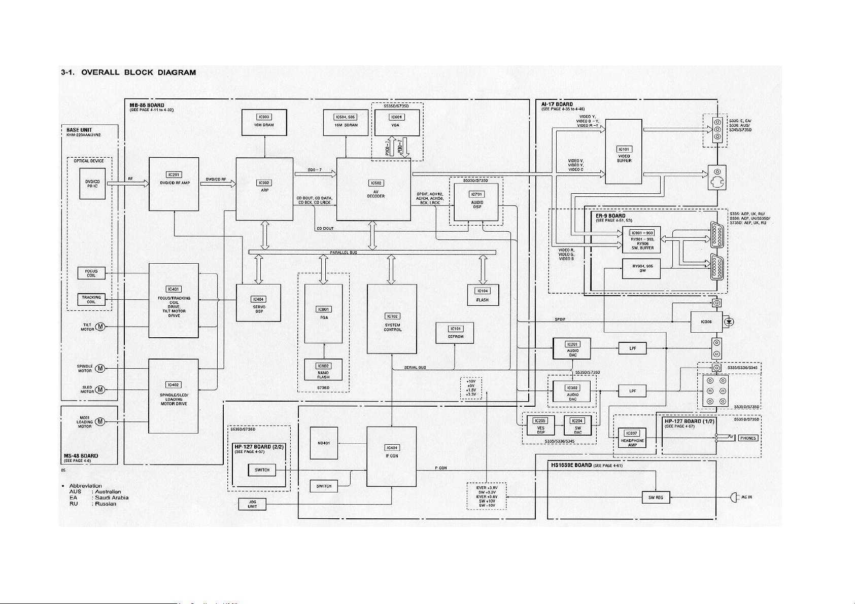
Block Diagram
There are also four major stages within this DVD player. They operate in this
sequence to produce the discs’ video and audio:
· Power Supply
· Communications
· Servo Control
· Video and Audio Processing
communication, never turning green when momentarily powering up at
switch on. After proper initialisation set is displaying blinking STANDBY word
an the display for a few seconds.
Power ON
At power ON, the red standby light turns to green and the output voltages
are turned on. After another brief communication between IC404 and IC102,
IC102 retrieves and implements the start up program stored in Flash
Memory IC104. The start up program requires IC102 to check for the
presence of these five ICs on the parallel bus and IC701 on the serial bus:
If an IC does not reply, IC102 instructs IC404 to power off the set.
Servo Control
At the successful conclusion of the start up program, IC102 retrieves servo
parameter data from EEPROM IC101 using the serial bus. Servo IC404 is
instructed to reset the base unit mechanism to the initial position
and confirm it:
· Tray closed
Power Supply
Comparing to 3rd Generation here Power supply block is equipped with
mechanical power switch and don’t have separate standby transformer.
After switching on mechanical power switch, switching power supply works
all the time. Difference between Standby and Power On mode is only in
blocking output of three switching output voltages (SW+3.3V, SW+10V, SW 10V). The power supply block delivers five different voltages at all. Ever
3.8V and Ever 5.6V (E+3V; E+5V) are the only voltages which are present
when the unit is in the Standby mode. E+3V powers interface IC404 to
switch on the remainder of the voltages when it receives the power ON (P
Cont) command.
Communications
Mechanical switch on
After switching on SW101, interface IC404 powers on the unit for 1.3
seconds, keeping the display dark. During this time there is a brief
communication between IC404 and system control IC102 on the serial bus.
The front panel red standby light is on during the entire initial
DVD 4th Generation
· Tilt servo at mid position
· Sled returned to home position
If the initial position is not confirmed before a time limit (“time out”), IC404
will power off the set. Confirmation comes from IC404(Servo) to IC102.
IC102 then sends commands back to servo IC404 for disc detection.
Video and Audio Processing
After the servos have begun, RF data will come from the optical assembly
within the base unit. The “eye pattern” RF data is split into two paths to
provide:
1. Feedback signal to lock the servos; and
2. Video and audio information.
The A/V processing chain is similar to one used in 3
3
rd
Generation
Page 4

Power Supply Block
The power supply is on a single board (HS-16S9E) located to the left of the
DVD mechanism. This board contains mechanical power switch and main
power supply.
DVD 4th Generation
4
Page 5

Main Power Supply
Unlike to 3rd Generation, Power supply of 4th Generation is not so
complicated and doesn‘t have separate Standby Power Supply. After
moving SW101 to On position Main Power Supply works all the time. During
standby mode three from five secondary voltages are blocked
This power supply produces all the time following voltages Ever 3.8V (E+3V)
and Ever 5.6V (E+5V). E+3V is supplied to interface IC404 (AI -17 board),
the mute transistors (AI -17 board) and E+5V for the IR receiver. The power
supply consists of an oscillator and an error regulator. The oscillator consists
of switch Q101 and a control transistor Q102. The oscillator output is applied
to T101. T101’s secondary voltages are rectified to five output DC voltages.
Regulation
The E+3Vdc output is used to regulate the main power supply. The Ever
3.8V voltage regulation circuit uses:
· IC301 – error detector
· PC101 – photocoupler
· Q102 – control transistor.
IC301 samples the E+3V output and produces a correction voltage.
Photocoupler PC101 passes the error voltage from the cold ground circuit to
the hot ground side circuit. The control transistor Q102 receives the error
voltage and uses it to alter the gate bias of switch Q101. The change in bias
alters the off time of the oscillator signal. This changes the oscillator
frequency. The changes in frequency affect the efficiency of the transformer,
which regulates the E+ 3V.
Remain three output voltages are switched ON by PCONT signal from the
Interface IC404/PIN66 on the AI-17 board. A “H“ at P-CONT enables output
DC voltages via switch Q711 and Q312. Only supply voltages E+3.8V and
SW+3.3V are fused.
Note: When a shorted e.g. spindle motor driver IC402 loaded the unfused
+10V supply line, the main oscillator quit! The oscillator worked again when
the short was removed.
DVD 4th Generation
5
Page 6

Other blocks.
Descriptions related to other blocks are in general very similar to ones from
rd
3
Generation material but you always have to keep in mind that IC used in
th
Generations are slightly different, so reader should carefully check
4
reference numbers of ICs and its related pins numbers.
This manual is based on the DVD-03 training course of:
Reworked by J. Dobrowolski / SONY Poland
All rights reserved. No part of this publication may be reproduced or transmitted in
any form or by any means, including photocopying, without the prior written
permission of European Technical Training (CRSE)
The publisher declines any liability for printing and information errors.
Subject to modification without prior notice.
DVD 4th Generation
6
 Loading...