

Sony DVP Service manual
DVP-NS415
Training Manual
DVP-NS655P
5th Generation
DVD Player
Models: DVP-NS300 DVP-NC650
DVP-NS315 DVP-NC655P
DVP-NS400D DVP-CX875P
DVP-NS415 DVP-F25
DVP-NS500P DVO-F41MS
DVP-NS700P
DVP-NS715P
DVP-NS755P
DVP-NC600
DVP-NS875P
Circuit Descriptions & Troubleshooting

Table of Contents
1. What’s New?......................................1
Physical Differences............................................. 1
Features ................................................................. 2
Dual Laser Optical Block ..................................... 3
Disc Identification .................................................. 5
Super Audio Compact Disc (SACD) .................. 6
Logos ...................................................................... 7
Video Noise Reduction ........................................ 8
2. Block diagram ..................................10
3. Power Supply ...................................12
Plug-In Communications .................................... 15
4. Testing and Test Point Access.......18
5. Testing ...............................................22
Jigs and Tools ....................................................... 25
6. Troubleshooting...............................27
Process Flow........................................................ 27
7. Service / Test Mode .........................32
8. Mechanical Operation .....................35
Powering the Unit ................................................. 34
CD Mechanism Normal Operation .................... 35
Disc Loading, Stacker and Disc Clamping
Motor Drive Access.............................................. 37
1. What’s New?
Chapter 1 - What’s New?
The popular fifth generation Sony DVD players introduced for the years 2001 and 2002 are physically and
electrically different from previous generation players; they have greater appeal and are lower in cost.
Physical Differences
The single disc players are thinner than the previous fourth generation models and take up less vertical space.
Some models are available in both black and silver (same model number) to blend with different decors. Two
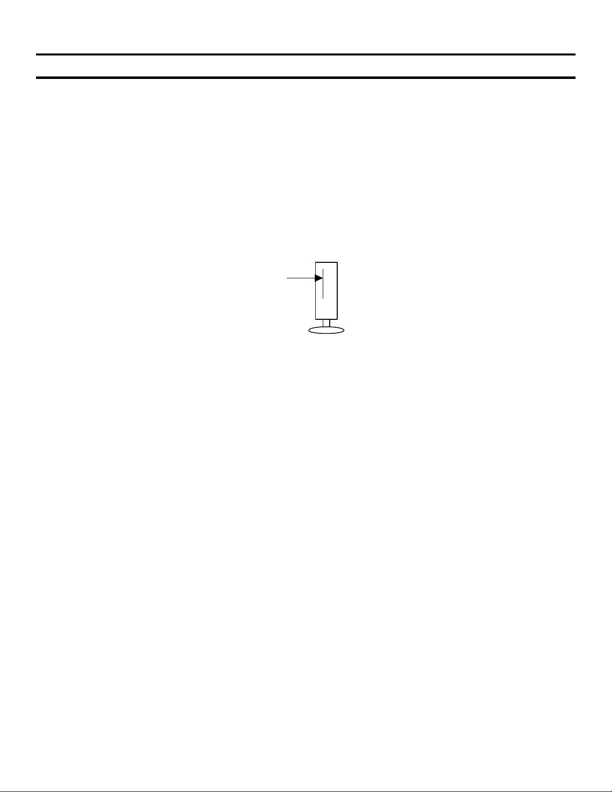
models, DVP-F25 and DVP-F41, have slot type loading (like a car CD player) which makes them smaller; they
can also be played horizontally or vertically; a pedestal base can be attached to the side for vertical mounting, as
in Figure 1-1.
DVD slot
Models DVP-F25 / F41
FIGURE 1-1 - VERTICAL MOUNTED “F” SERIES DVD PLAYER
1

1. What’s New?
Features
These players can play computer “burned” -R and +RW (CD or DVD) discs. A built-in MP-3 decoder allows MP3 encoded CD’s to be played. All 5th generation players have outputs for composite video, component video (Y,
R-Y, B-Y) and Dolby Digital ™ / dts ® digital coax/optical digital audio (except DVP-F25 and DVP-F41 models
which only have high grade component video and optical audio outputs) Other features on some models are:
multi-format SACD music CD PB (audio); and high resolution 480p progressive video output.
Table 1-1 shows some of the features of the Fifth Generation models.
Table 1-1 - Sony’s Popular Fifth Generation DVD Players
Model Number Intro
Year *
DVP-NS300 2001 1 disc tray Case = Blk or Silver finish. Does not
DVP-NS315 2002 1 disc tray Black or Silver finish
DVP- NS400D 2001 1 disc tray Built in 5.1 Digital Dolby Decoder
DVP- NS415 2002 1 disc tray Silver, Built in 5.1 Digital Dolby
DVP- NS500P 2001 1 disc tray Progressive scan
DVP- NS700P 2001 1 disc tray Progressive scan
DVP- NS715P 2002 1 disc tray Progressive scan, Silver
DVP- NS755P 2002 1 disc tray Progressive scan, SACD, Built in 5.1
DVP-NC600 2001 5 disc Changer No thinner case like the tray units.
DVP-NC650 2001 5 disc Changer SACD
DVP-NC655P 2002 5 disc Changer Progressive scan, Blk/Silver.
DVP-CX875P 2002 300 disc changer Progressive scan, Built in 5.1 Digital
DVP-F25 2002 1 disc slot Case = Blk or Silver finish.
DVP-F41MS 2002 1 disc slot Memory stick for JPEG pix view
Type Feature
PB –R or +RW discs.
Decoder
Digital Dolby Decoder, Blk.
Dolby Decoder.
* Optical Assemblies for 2001 year Models are KHM240AAA and KHM250AAA Optical
Assemblies for 2002 year Models are KHM270AAA and KHM275AHA.
2
1. What’s New?
Dual Laser Optical Block
Disc Playback Characteristics
All fifth generation DVD models, (except basic model DVP-NS300) can play back computer made –R or +RW
discs.
Computer made (burned) –R or +RW discs have different characteristics than machine stamped counterparts
and stamped CDs have different characteristics than DVDs. To insure full compatibility, the optical block uses
two lasers. One is optimized for CDs and the other for DVDs.
To understand how separate lasers insure playback of computer burned discs, some basics are explained here.
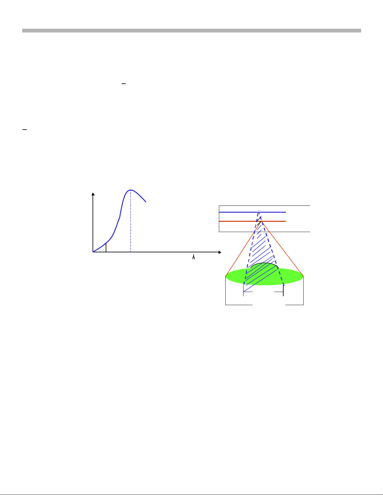
The reflected Laser light from the disc to the optical block contains the data. DVD discs (including DVD-R and
+RW discs) reflect best in the 650-635nM wavelength band. CD discs (including –R or +RW discs) reflect light
best at 780nM.
Figure 1-2 shows that maximum CD-R disc reflection (RF) occurs at 780nM. Since –R or +RW discs have lower
reflectivity than stamped discs (reflectivity also varies from brand to brand) output is maximized if two lasers are
used: one operating at 648nM for DVDs and another at 780nM for CDs.
Optical Pick -up
Reflective
Intensity for
CD-R
650nM
780nM
Wavelength
FIGURE 1-2
CD = 1.2cm
DVD=0.6cm
KHM-240
Lens
For CD
For DVD
3
1. What’s New?
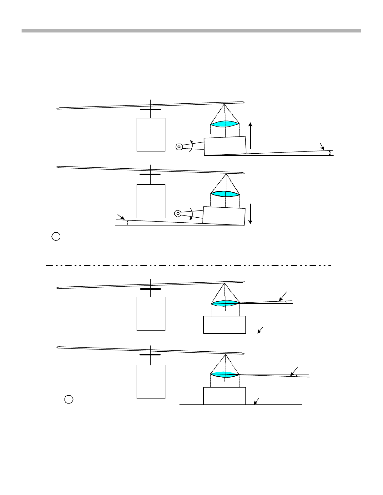
Disc Warp Correction
Because of the finer DVD pitch, the laser must be perpendicular to the disc for maximum RF output from the
optical block. Figure 1-3 illustrates the differences between old servo tilt mechanism system (A) and the new
DTC system (B) that keeps the laser beam perpendicular. In earlier generations, a tilt servo (A) adjusted the
angle of the laser platform to keep the monitored RF level at peak. This system is complex and the platform can
“bottom out”, limiting its range.
DISC
DISC
WHOLE
ASSEMBLY
ROTATES
FROM
HORIZONTAL
A TILT SERVO WARP
DISC COMPENSATION
DISC
MOTOR
PIVOT
PIVOT
LENS
ASSEMBLY
LENS
ASSEMBLY
LENS
OPTICAL
OPTICAL
PIVOTS UP
PIVOTS
DOWN
(LIMITED RANGE)
ASSEMBLY
HORIZONTAL
ILLUSTRATES
ROTATION OF
LENS
ONLY
WHOLE
ROTATES
FROM
DISC
B DTC WARP
DISC COMPENSATION
OPTICAL
ASSEMBLY
LENS
OPTICAL
ASSEMBLY
ASSEMBLY REMAINS
ASSEMBLY REMAINS
FIGURE 1-3 - TILT SERVO (A) VS. DTC (B)
4
HORIZONTAL
ILLUSTRATES
ROTATION OF
LENS
ONLY
HORIZONTAL
GGW5 1545 4/9/03
1. What’s New?
In fifth generation DVD players, an ingenious Dynamic Tilt Correction (DTC) system replaces the tilt servo.
Warped disc readability is achieved by tilting the lens during focus correction. The greater the focus correction,
the more the tilt.
The DTC concept and mechanics are as follows:
The DVD disc information layer is at a height determined by the spindle motor hub. This is considered as the
mechanical focus center of the lens. As the optical block moves towards the outside of the disc, disc warp
increases. At the points where the disc is angled up by warp, the focus point also moves up to compensate.
Raising the focal point causes the lens to change its angle and remain perpendicular to the disc. Conversely,
when the disc angles down (Figure 1-2 B), the lens focus goes below center and the lens tilts in the opposite
direction.
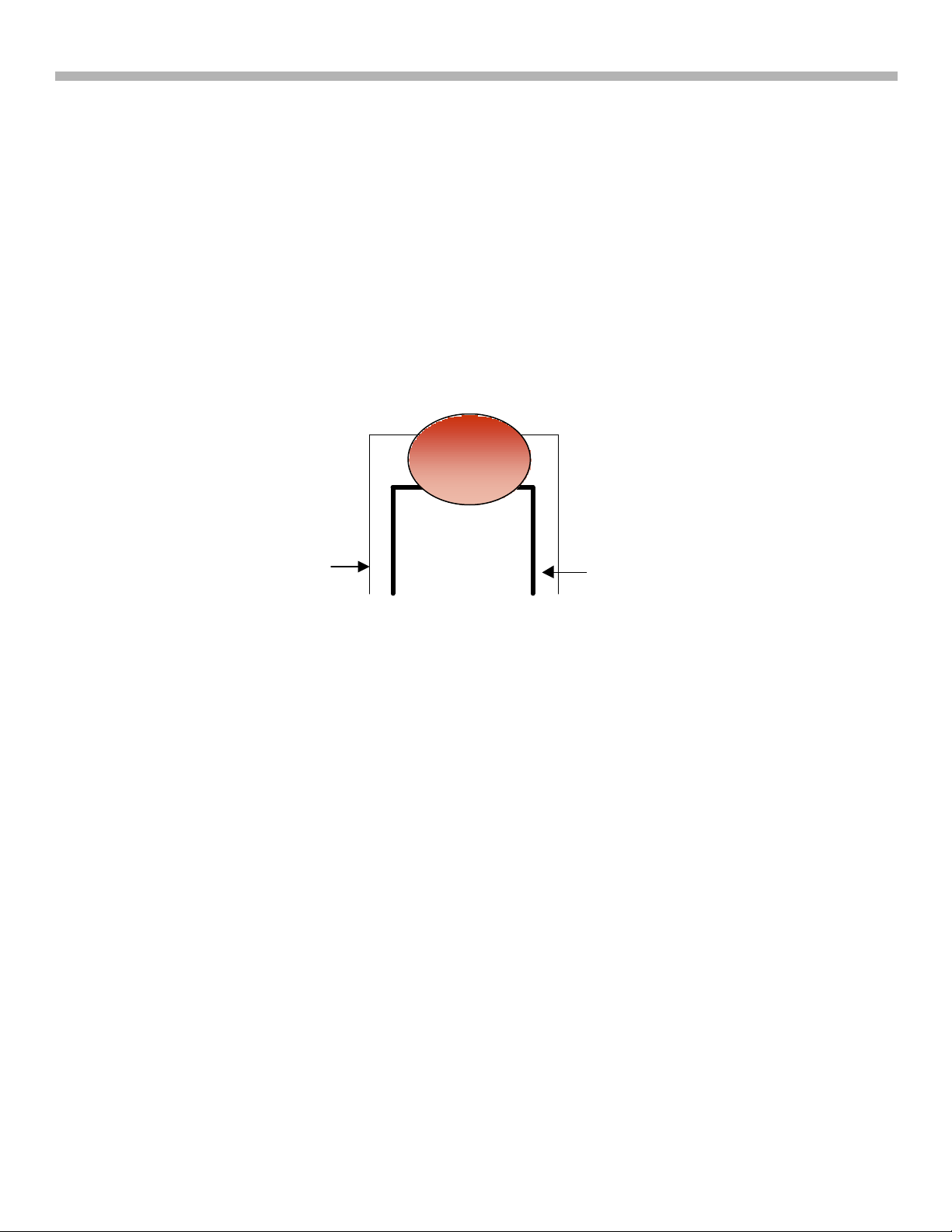
Mechanically, DTC is achieved by modifying the lens supports. The front lens supports are stronger than the
rear. See Figure 1-4. As the lens moves up, it is tilted toward the weaker support. As it moves down, the lens is
tilted toward the stronger support. The tilt is always in the direction of the warpage so the lens remains perpendicular
to the disc.
Figure 1-4 - Lens
Retaining DTC System
Lens
Weak
Rear
Support
Stronger
Front
Support
FIGURE 1-4 - DTC SYSTEM
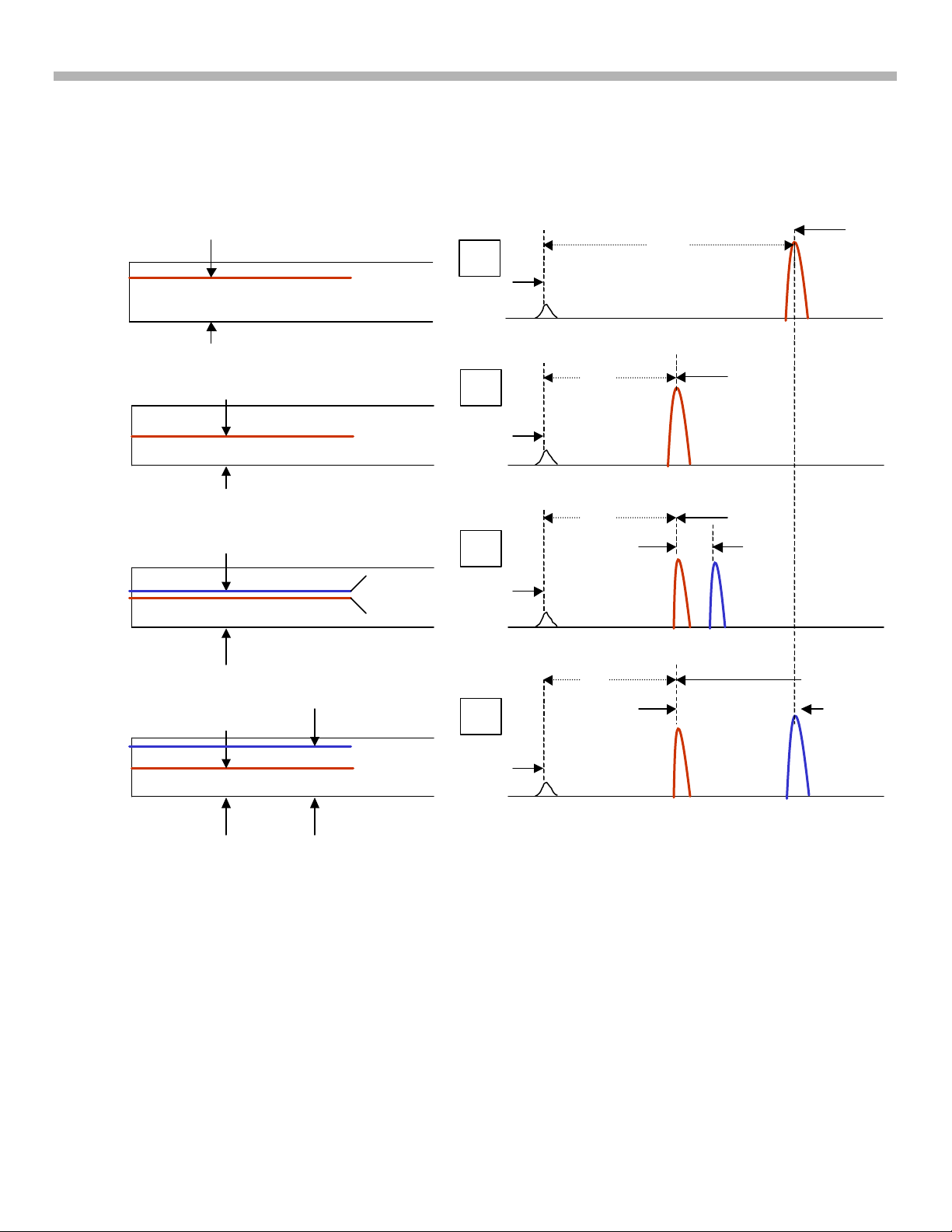
Disc Identification
The DVD player first determines what type of disc is in the tray before playing it. The player powers up one of the
lasers and begins looking for the disc’s information layer(s). The time it takes to find a layer determines how
deep the layer is inside the disc (T=0.6cm, 2T =1.2cm). Because the tracking servo is disabled at this time, the
lens will continue past the focus point of the DVC and look for a second information layer (DL disc). The disc ID
method is shown in Figure 1-5. This procedure is repeated with the second laser to insure identification of the
lower output –R and +RW discs.
5
1. What’s New?
Figure 1-5 also shows that the laser takes the least time to find a DVD disc (Figure 1-5, B, C, or D). If a second
focal point is also found, the disc is either a dual layer DVD (Figure 1-5 C) or SACD (Figure 1-5 D).
Disc Type
CD
DVD/
SACD
SL
DVD/
SACD
DL
1.2 CM
0.6 CM
0.6 CM
DISC IDENTIFICATION
A
INFO LAYER
DISC ENTRY
B
INFO LAYER
DISC ENTRY
C
2nd LAYER
1st LAYER
DISC ENTRY
T
T
2T
t
CD
SL
DL
DL
T
SACD layer CD layer
SACD-
Hybrid
0.6 CM
D
CD layer
HD LAYER
1.2 CM
DISC ENTRY
FIGURE 1-5 - DISC IDENTIFICATION
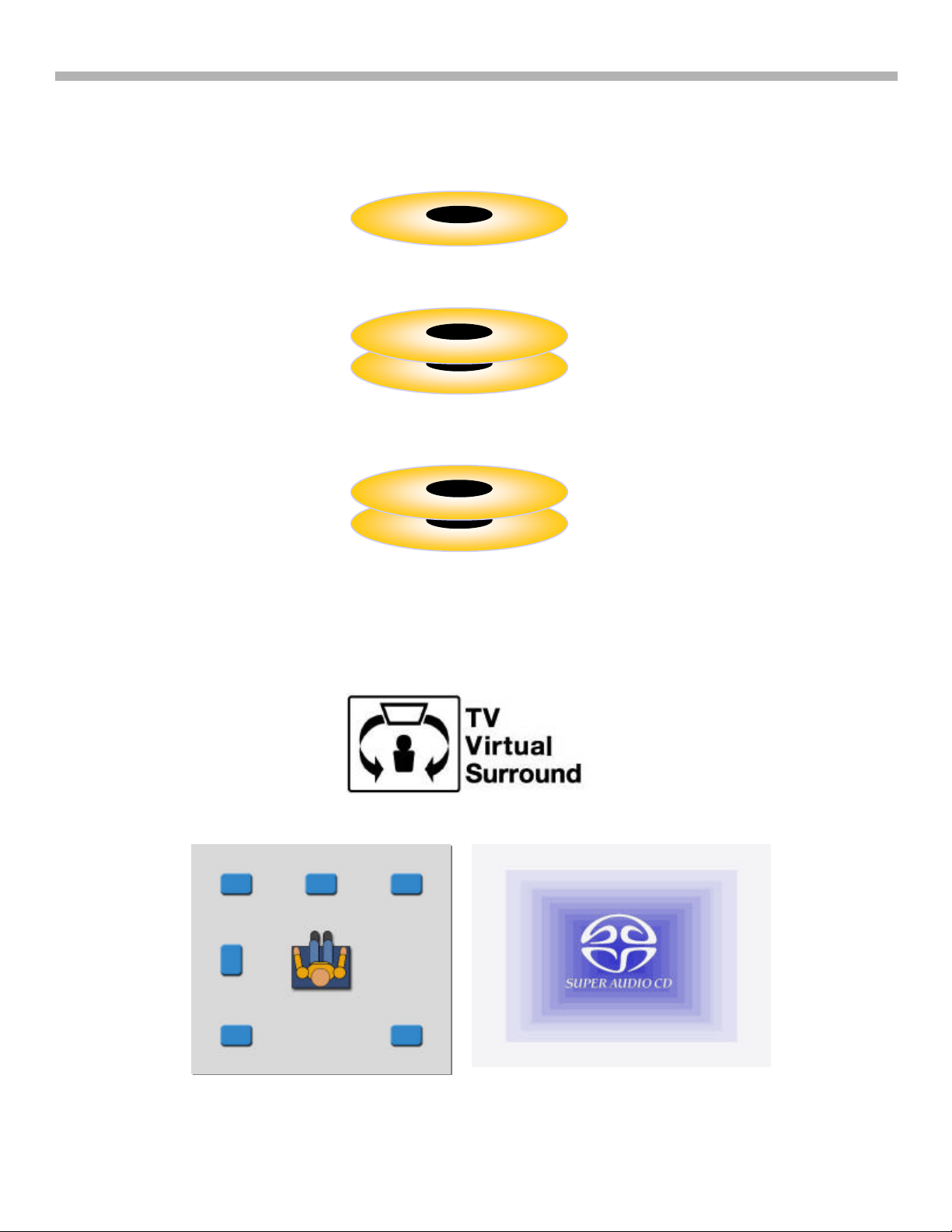
Super Audio Compact Disc (SACD)
There are three types of SACDs, all played from the bottom of the disc (disc is not flipped over): See Figure
1-6.
1. Single Layer: The single high-density (HD) layer can contain 2 channel and multi-channel DSD recordings,
text (such as song tiles and lyrics), video clips and graphics.
t
hybrid
6
1. What’s New?
Single layer disc
Hybrid disc
layer
layer
2. Dual layer - Two layers with twice the playing time / information as a single layer.
3. Hybrid layer – Contains one HD layer and a standard CD layer so it can be played on any standard CD player
too.
HD
Dual layer disc
2 HD layers
CD layer
HD
FIGURE 1-6 - SACD TYPES
Logos
High-end products that can play one or all versions of SACD discs have at least one of three of the logos
shown in Figure 1-7.
Front L Center Front R
Subwoofer
Rear L Rear R
FIGURE 1-7 -SACD LOGOS
7
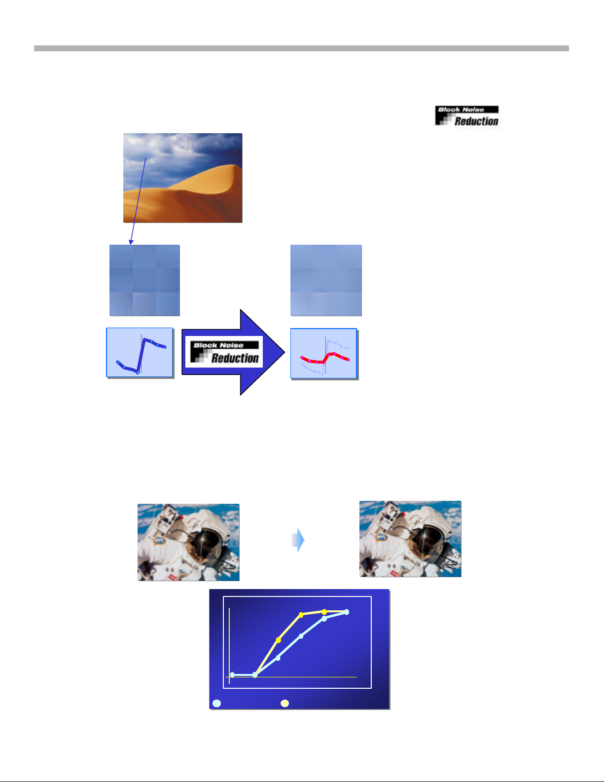
Video Noise Reduction
Block Noise Reduction (BNR)
BNR reduces dissimilarities (noise) at the edges of blocks (Figure 1-8).
Block Noise Reduction
The Block Noise Reduction reduces noise at vertical
rising (block) edges caused by the MPEG format.
The picture looks more smother and more natural.
Picture details, even very small once, are not effected.
1. What’s New?
FIGURE 1-8 - BLOCK NOISE REDUCTION
Digital Video Enhancer (DVE)
DVE corrects the frequency response of the video signal and emphasizes picture details, see Figure 1-9. Since
DVE (Digital Video Enhancer) emphasizes BLOCK NOISE, the BNR circuit is used before the DVE .
DVE = Digital Video Enhancer
it emphasizes picture details
U
f
: Original Signal
: Original Signal
: Original Signal
: Optimized Signal
: Optimized Signal
: Optimized Signal
FIGURE 1-9 - DIGITAL VIDEO ENHANCER
8

Digital Video Enhancer & Block Noise
Former generation (year 2000)
Former generation (year 2000)
Reduction
DVEDVE
DVEDVE
DVE
DVE
5th generation
5th generation
Might emphasize
Might emphasize
Block Noise!
Block Noise!
1. What’s New?
BNR
BNR
BNR
BNR
BNR
BNR
At first,reduce
At first,reduce
Block Noise.
Block Noise.
No emphasis of Block Noise, clear edge and
No emphasis of Block Noise, clear edge and
details retained.
details retained.
DVEDVE
DVEDVE
DVE
DVE
FIGURE 1-10 - BNR AND DVE ORDER
9
2. Block Diagram
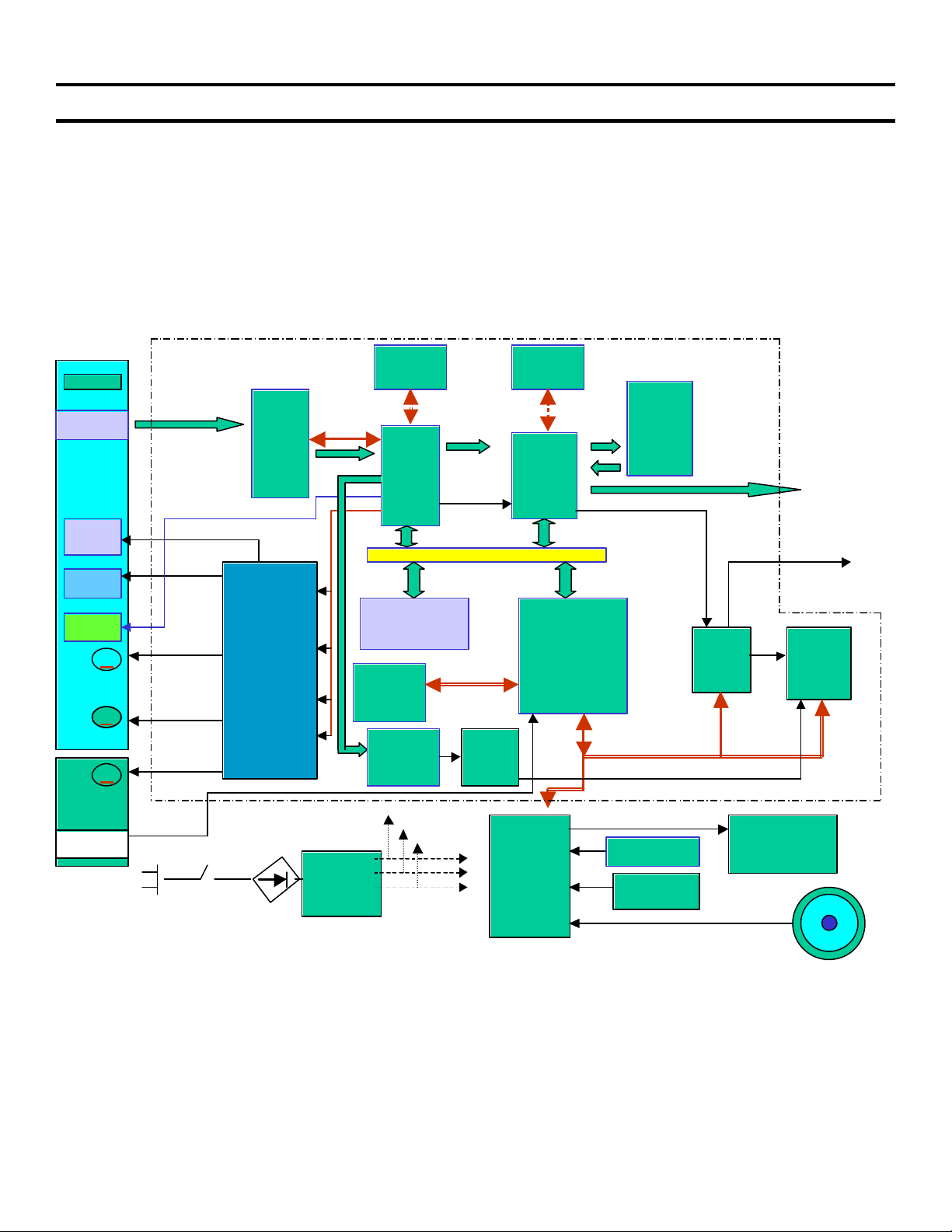
Chapter 2 - Block Diagram
Figure 2-1 shows a block diagram of fifth generation DVD players. They have the following features:
• New type of optical pickup unit. (CD or DVD laser selection not shown.)
• All analog Driver functions input to one IC (“IF Con”).
• No External RAM for Syscon IC.
• Block Noise Reduction IC.
• ARP and Servo DSP is combined in one IC.
Base Unit
DVD/CD
PD IC
Focus
Coil
Tracking
Coil
INLIMIT
Sensor
M
SP_Motor
M
Sled Motor
M
Loading
Motor
Chuck Tray
Detect
16MB
DRAM
16/ 64MB
SDRAM
BNR
RF Amp
ARP
Servo
DSP
CDDOUT
CDData
CDBCK/LRCK
Parallel Bus
AV
Decoder
V,Y,C
SPDIF OUT
Video Buffer
SPDIF
FLASH or OTP
Focus / Tracking
Coil Drive,
Spindle / Sled/
Loading Motor
Drive
EEPROM
SACD
DECODER
Syscon
SACD
BASS
Manag.
Audio
DSP
Receiver RC
)
SW
Regulator
IF Con
Fn Key
Audio
D/A
Converter
ND401
FLD
FIGURE 2-1 - BLOCK DIAGRAM
10
2. Block Diagram
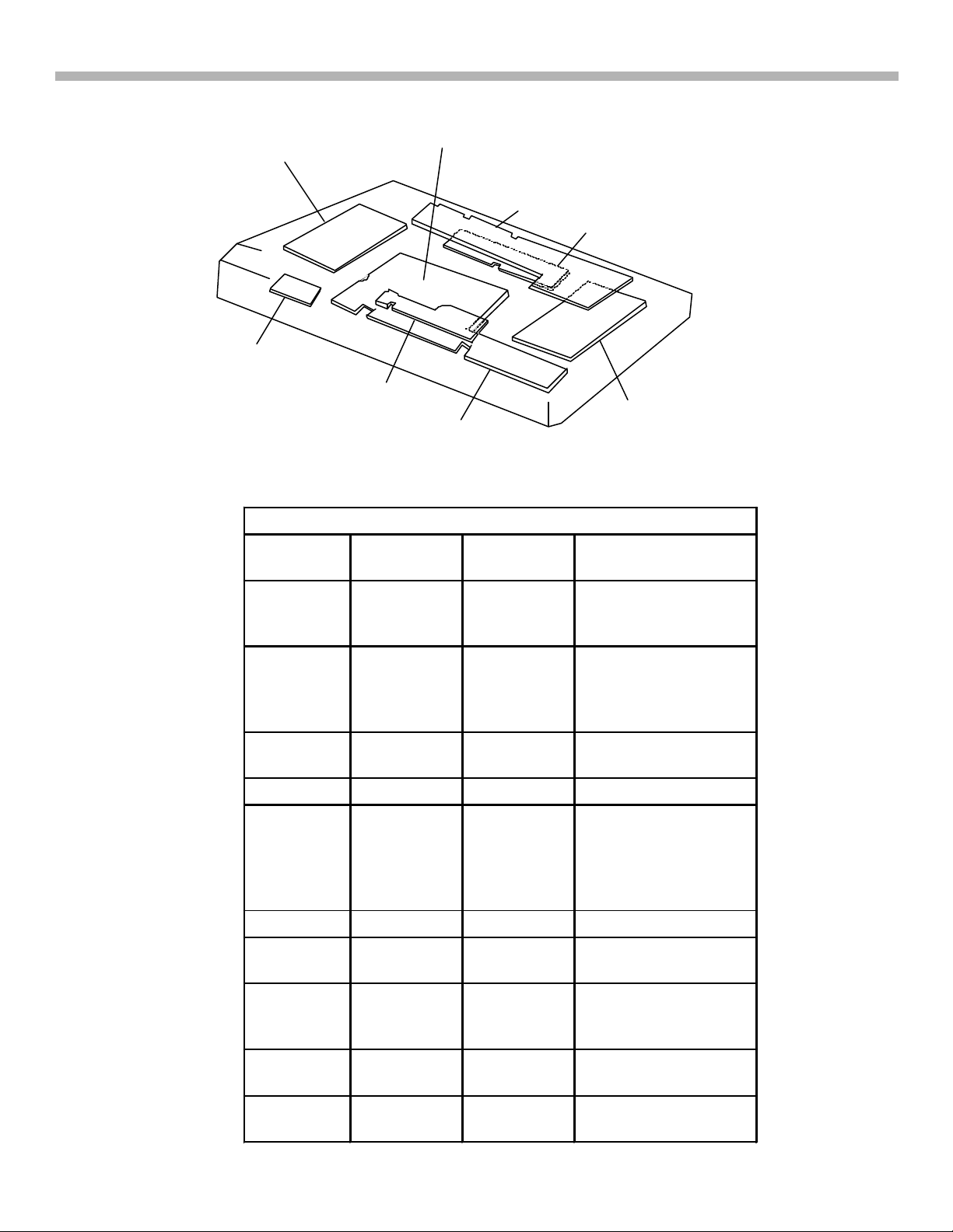
CIRCUIT BOARDS LOCATION
DVP-NS400/700
POWER BLOCK (HS15S1U)
NS500V)
(SWITCHING REGULATOR)
HS13SO3 IN -NS400
SI-31
(REMOTE COMMANDER
RECEIVER)
NOT IN -NS400
AI-23 FOR NS-400
(COMPLETELY DIFFERENT,
INCLUDES: AUDIO/VIDEO/
INTERFACE CONTROL
AV-59 NOT IN -NS400
(AUDIO/VIDEO OUT)
ER-15 IN -NS400
MS-81
(LOADING)
IF-84
(INTERFACE CONTROL)
MB-101
(SIGNAL PROCESS, SERVO)
MB-98 IN -NS400
FIGURE 2-2 - CIRCUIT BOARD
Table 2-1 - MB Board Main IC Functions
IC Name DVP-NS400
Ref Number
RF Amp /
IC202 IC201 DVD/CD RF Amp,
Digital
DVP-NS700
Ref Number
Purpose
Servo
Servo
EEPROM IC101 IC101 Servo Setting Data,
Emer. History, Hour
meter, Disc
Parameters.
Flash /
OTP
IC107 IC106 &
IC107
Start up instructions /
sequence ROM
Syscon IC103 IC104 Overall Operation
(ARP) /
Servo DSP
Advanced
IC302 IC302 CD/DVD Data
Processing, Servo
Control.
RF
Processor
16M DRAM IC303 IC301 RAM for ARP IC302
BNR IC601 IC504 Black Noise
Reduction
A/V
Decoder
IC503 IC502 MPEG2, AC-3 ®
(Dolby Digital)
decoder
64M
SDRAM
Analog
IC504 /
IC507 RAM for A/V Decoder
IC505
IC401 IC202 Analog Servo Control
Servo
11
3. Power Supply
Chapter 3 - Power Supply
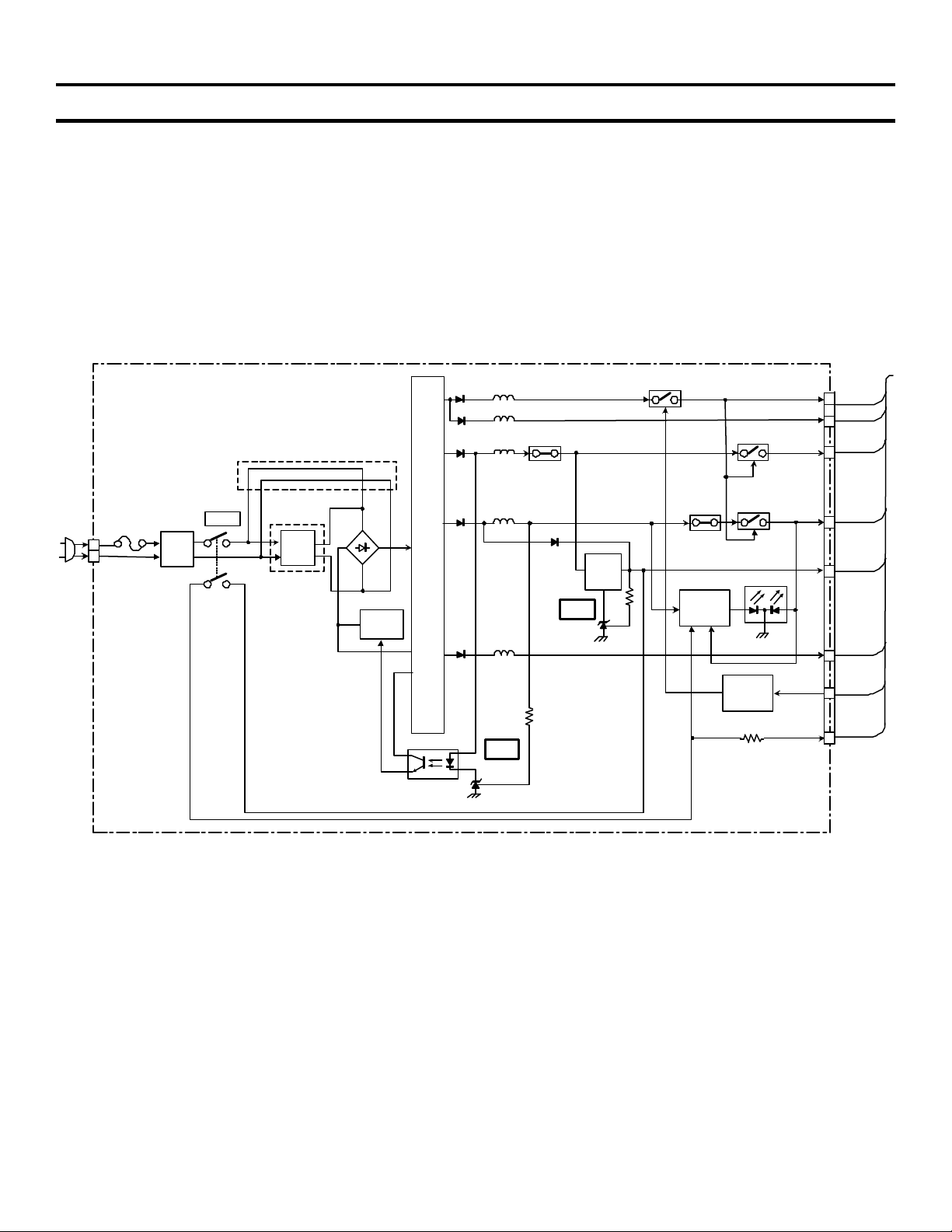
Power Supply
The 5th Generation power supplies have the following features:
• No STANDBY circuit (Hard wire ON / OFF switch SW101).
• Simple MAIN POWER SUPPLY circuit. Q101 = switching osc. Q102 / PC101 / IC301 = feedback.
• Simple Stdby/Power ON controll.
Figure 3-1 shows a block diagram of the power supply:
HS15S1E BOARD: AEP, UK, AUS, E, EA, HK, KP, ME, RUS, SP, CH
(SEE PAGE 4-53)
HS15S1U BOARD: US, CND
(SEE PAGE 4-61)
HS15S1J BOARD: TW
(SEE PAGE 4-57)
US. CND. TW
D211
D221
D311
L211
L221
L311
P311
Q211
Q311
SW
6
+11V
7
EVER +11V
13
+5V
12
AC IN
1
2
CN101
F101
L101
LINE
FILTER
SW101
POWER
EXCEPT
US. CND. TW
FILTER
EVER +3.3V
L102
LINE
Q101, 102
OSC
T101
PC101
PHOTO
COUPLER
D611
D511
L611
L511
IC301
SHUNT
REG
D413
IC411
SHUNT
REG
Q411
+3.3V
REG
P611
D621 (ON/STANDBY)
Q621, 622
LED DRIVE
CONTROL
Q611
Q712
POWER
8
11
3
2
1
SW
+3.3V
EVER
+3.3V
EVER
-11V
P-CONT
P-DET
FIGURE 3-1 - POWER SUPPLY
Power ON Operation
The power supply circuitry before T101 (Primary) and after (Secondary) are explained. Refer to Figures 3-1 for
the block diagram. The load and additional regulators are shown in Figure 3-2.
Primary
After closing main switch SW101, oscillator circuit Q101 and the primary coils of T101starts. Regulation comes
from sampling the secondary +3.3 V at L611. The sample is sent to inverter/shunt regulator IC301, to the optocoupler PC101 and finally back to oscillator Q101.
EVER +3,3V from Q411 is switched via the other leg of SW101 and is applied to power ON LED D621 (RED)
drive. It is also applied to IC404/pin19 (not shown) as a P-DET signal. The output of IC404 controls the rest of
the power supply secondary circuit via the P-CONT line. EVER +3.3V powers IC404, IR remote receiver, cursor
stick and audio muting (all not shown).
12
 Loading...