

Sony DV-MECHA Service Manual
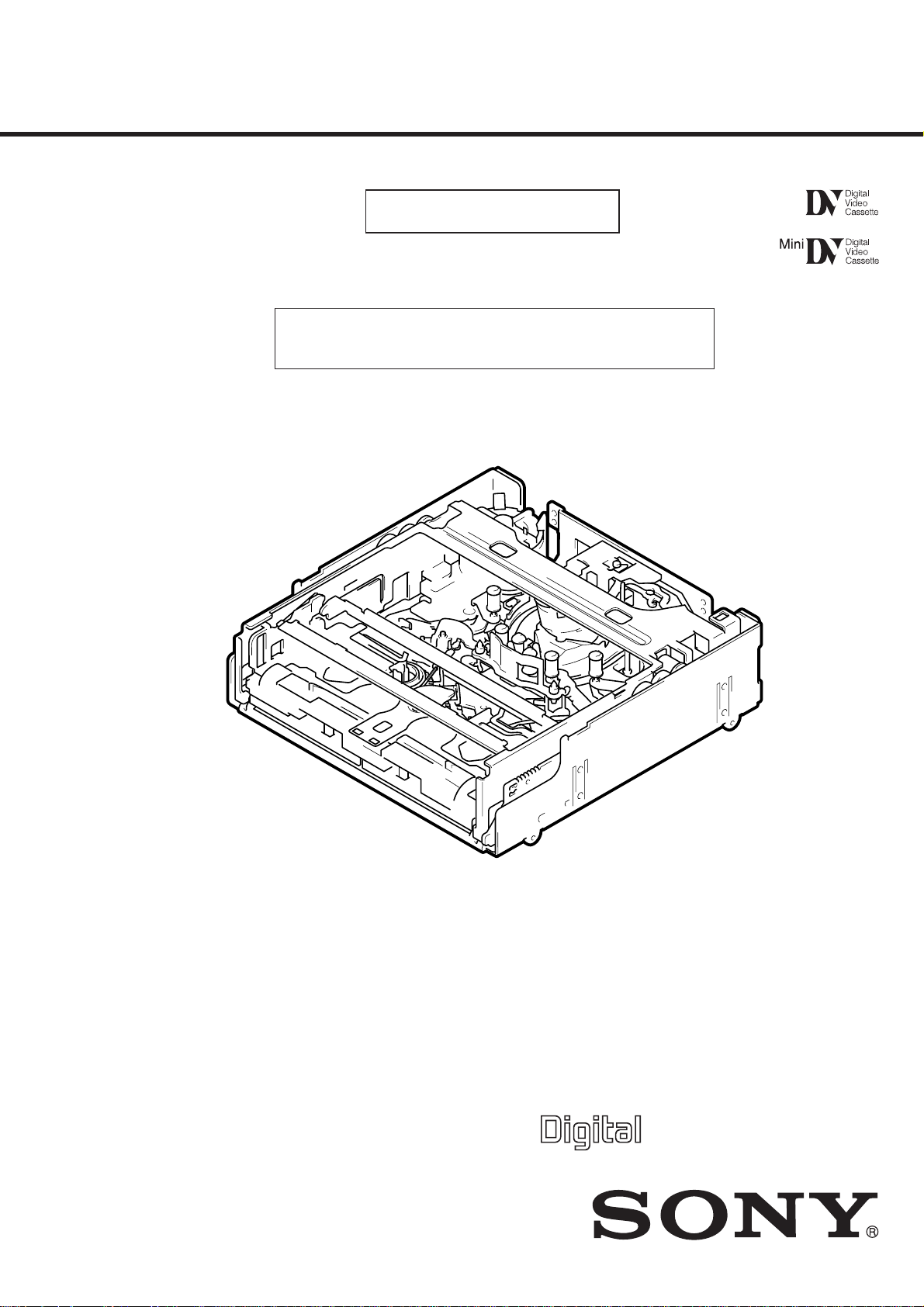
DV MECHANICAL ADJUSTMENT MANUAL V
Ver 1.0 2000. 10
R MECHANISM
Please use this manual with the service manual.
For details on printed circuit boards diagram, schematic diagram,
and electric parts list regarding this mechanism deck, refer to
the service manual for the unit mounting the R mechanism.
MECHANISM DECK

TABLE OF CONTENTS
1. PARTS REPLACEMENT AND PREPARATION
FOR ADJUSTMENT
1-1. ASSEMBLY/DISASSEMBLY OF CASSETTE
COMPARTMENT ······························································ 4
1-2. HOW TO LOAD/UNLO AD··············································· 4
1-3. Service Jigs and Tools ························································ 5
1-4. About Mode Selector II ······················································ 6
4-1. OUTLINE··········································································· 6
1. Manual test ········································································· 6
2. Step test ··············································································6
3. Auto test ·············································································6
4-2. MECHANISM CONDITION (POSITION)SHIFTING
ORDER LIST ····································································· 6
4-3. MODE SELECTOR II CONNECTION ····························6
2. PERIODIC CHECK
2-1. CLEANING OF ROTARY DRUM ASSEMBLY ·············· 7
2-2. CLEANING OF TAPE PATH SYSTEM ··························· 7
2-3. PERIODIC CHECKS·························································7
3. PARTS REPLACEMENT
3-1. TAPE GUIDE 1/8 AND GUIDE GUARD·························8
3-2. TAPE GUIDE 2/7 ······························································· 8
3-3. CAPSTAN COVER ···························································· 9
3-4. REEL MOTOR··································································· 9
3-5. FL MOTOR ASSEMBLY, GEAR A, GEAR B AND
GEAR CD ASSEMBLY ····················································· 9
3-6. GL ARM S ASSEMBLY, GL ARM T ASSEMBLY,
COASTER S ASSEMBLY AND COASTER T
ASSEMBLY ·····································································10
3-7. MIC BASE GUIDE, MIC BASE ASSEMBLY AND
MIC BASE SPRING ························································ 11
3-8. DRUM CAP, DRUM ASSEMBLY AND TAPE
SUPPORT········································································· 11
3-9. PINCH ARM ASSEMBL Y ··············································12
3-10. CAPSTAN MOTOR ························································· 12
3-11. PENDULUM RETAINER AND PENDULUM ARM
ASSEMBLY ·····································································12
3-12. BRAKE ARM S, RATCHET BRAKE T, TENSION
COIL SPRING (BRAKE), SBR SLIDER AND FP-248
FLEXIBLE BOARD (CONDENSATION SENSOR) ·····13
3-13. REEL TABLE ASSEMBLY, IDLER GEAR A
ASSEMBLY AND IDLER GEAR B ·······························13
3-14. REEL BASE RETAINER, REEL BASE T ASSEMBLY
AND REEL BASE S ASSEMBLY
(REEL LOCK RELEASE BLOCK AND REEL LOCK
RELEASE SPRING) ························································ 14
3-15. CAM MOTOR, MOTOR HOLDER ································ 14
3-16. TG2/7 ARM BLOCK, TG2/7 BAND BLOCK AND
TENSION COIL SPRING (TG2)/(TG7) ························· 15
3-17. SUB-SLIDER ARM, SUB-SLIDER, ENCODER GEAR,
MAIN CAM GEAR, COUPLING GEAR, SUB-CAM
GEAR, PINCH SLIDER AND LOADING ARM ASSY ·· 16
3-18. MAIN SLIDER, MAIN SLIDER ARM AND
PENDULUM STOPPER ASSEMBLY ···························· 18
3-19. MD-76 BOARD AND ENCODER RETAINER ·············· 19
3-20. COMPONENTS OF GL ARM S/T ASSEMBLY
(GL ARM ASSEMBLY, GL HELICAL TORSION
SPRING, GL GEAR) ······················································· 20
3-21. COMPONENTS OF MIC BASE ASSEMBLY
(FP-104 FLEXIBLE BOARD, MIC BASE) ···················· 20
3-22. COMPONENTS OF DRUM ASSEMBLY
(MOTOR FPC ASSEMBLY, ELASTIC CONNECTOR) ·· 21
3-23. COMPONENTS OF PINCH ARM ASSEMBLY
(TAPE RETAINER, COMPRESSION COIL SPRING)·· 21
3-24. COMPONENTS OF TG2/7 ARM ASSEMBLY
(ET MAGNET, MAGNET HOLDER)····························· 21
4. CHECK AND ADJUSTMENT
4-1. REEL TABLE HEIGHT CHECK AND ADJUSTMENT 23
1. Preparation before check ·················································· 23
2. Check and adjustment ······················································ 23
4-2. TG1/8 HEIGHT CHECK AND ADJUSTMENT ············· 23
1. Preparation before check ·················································· 23
2. Check and adjustment ······················································ 23
4-3. TG2/7 HEIGHT CHECK AND ADJUSTMENT ············· 24
1. Preparation before check ·················································· 24
2. Check and adjustment ······················································ 24
4-4. FWD/RVS POSITION CHECK AND ADJUSTMENT ·· 24
1. Preparation before check ·················································· 24
2. Check and adjustment ······················································ 24
4-5. ELECTRIC TENSION REGULATOR CHECK AND
ADJUSTMENT OF TG2/7 ARM ···································· 25
1. Preparation before check ·················································· 25
2. Check and adjustment ······················································ 25
4-6. FWD/RVS BACK TENSION CHECK AND
ADJUSTMENT································································26
1. Preparation before check ·················································· 26
2. Check and adjustment ······················································ 26
4-7. PREPARATION FOR ADJUSTMENT AND
TAPE PATH CHECK ······················································· 26
4-8. TRACK ADJUSTMENT AND CHECK
(Checking the RF Waveform)···········································27
4-9. TRACK CHECK ······························································ 27
4-10. CUE/REV CHECK ·························································· 28
4-11. CURL CHECK AND ADJUSTMENT ···························· 28
4-12. RISING CHECK ······························································ 29
5. REPAIR PARTS LIST
5-1. EXPLODED VIEWS ······················································· 30
5-1-1.DRUM SECTION ···························································· 30
5-1-2.GEAR, ARM SECTION ·················································· 31
5-1-3.MOTOR, MD-76 BOARD SECTION ····························· 32
5-1-4.CASSETTE COMPARTMENT BLOCK ASSEMBLY··· 33
5-2. ELECTRICAL PARTS LIST ··········································· 34
6. PRINTED WIRING BOARD AND
SCHEMATIC DIAGRAM
• MD-76 (MODE SENSOR)
PRINTED WIRING BOARD ·························· 35
• MD-76 (MODE SENSOR)
SCHEMATIC DIAGRAM ······························· 37
— 2 —
assigned to each part in the exploded views of Section 5, “Repair
Tape guide 1
(Drawing numbers: 710 to 714)
Cassette
compartment
(Drawing numbers:
722, 851)
FL motor block
(Drawing numbers: M905, 853 to 856)
GL arm S/T block
(Drawing numbers: 810 to 817)
Coaster S/T Block
(Drawing numbers: 801 to 802)
MIC base guide
(Drawing numbers: 702)
MIC base assembly
(Drawing numbers: 701, 703, 723, 724, CN004, S004)
Drum cap
(Drawing numbers: 721)
Drum assembly
(Drawing numbers: M901)
Tape support
(Drawing numbers: 717)
Pinch arm assembly
(Drawing numbers: 718 to 720)
Capstan cover
(Drawing numbers: 819)
Capstan motor
(Drawing numbers: M903)
Tape guide 8
(Drawing numbers: 710 to 714)
Tape guide 2
(Drawing numbers: 776 to 780)
Tape guide 7
(Drawing numbers: 776 to 781)
Guide guard
(Drawing numbers: 715)
Capstan cover
(Drawing numbers: 819)
Reel motor
(Drawing numbers:
M904)
Pendulum retainer
(Drawing numbers: 705)
Pendulum
retainer
(Drawing
numbers: 705)
Pendulum arm assembly
(Drawing numbers: 706)
Brake arm S/Ratchet brake T
(Drawing numbers: 707, 708, 709)
SBR slider
(Drawing numbers: 757)
Cam motor
(Drawing numbers: M902)
Idler gear A/B
(Drawing numbers: 751, 752)
Motor holder block
(Drawing numbers: 763, 764, M902)
TG2 arm/TG2 band block
(Drawing numbers: 766, 768, 771 to 775)
TG7 arm/TG7 band block
(Drawing numbers: 767, 769, 770, 775)
Sub-slider arm
(Drawing numbers: 761)
Sub-slider
(Drawing numbers: 758)
Main cam gear
(Drawing numbers: 755)
Coupling gear
(Drawing numbers: 762)
Sub-cam gear
(Drawing numbers: 756)
Pinch slider
(Drawing numbers: 760)
Loading drive lever
(Drawing numbers: 759)
Main slider
(Drawing numbers: 820)
Brake arm S
(Drawing numbers: 708)
Main slider arm
(Drawing numbers: 803)
Encoder cover
(Drawing numbers: 818)
MD-76 board
(Drawing numbers: 824, etc.)
Pendulum stopper assembly
(Drawing numbers: 805)
Encoder gear
(Drawing numbers: 754)
Reel table S/T
(Drawing numbers: 753)
Reel base retainer
(Drawing numbers: 829)
Reel base S/T block
(Drawing numbers: 822, 823, 827, 828)
FP-248 flexible board (condensation sensor)
(Drawing numbers: 821)
Page 4
Page 9
Page 10
Page 11
Page 11
Page 12
Page 13
Page 13 Page 13
Page 11
Page 12
Page 12
Page 13
Page 14
Page 15 Page 16
Page 16 Page 16
Page 16
Page 13
Page 18 Page 18
Page 19 Page 19
Page 18
Page 16
Page 16
Page 16 Page 16
Page 15
Page 12
Page 14
Page 8
Page 8
Page 8
Page 8
Page 13
Page 14 Page 14
Page 9 Page 12
Page 11
Page 20
Page 10
Page 8
Page 9
Page 9
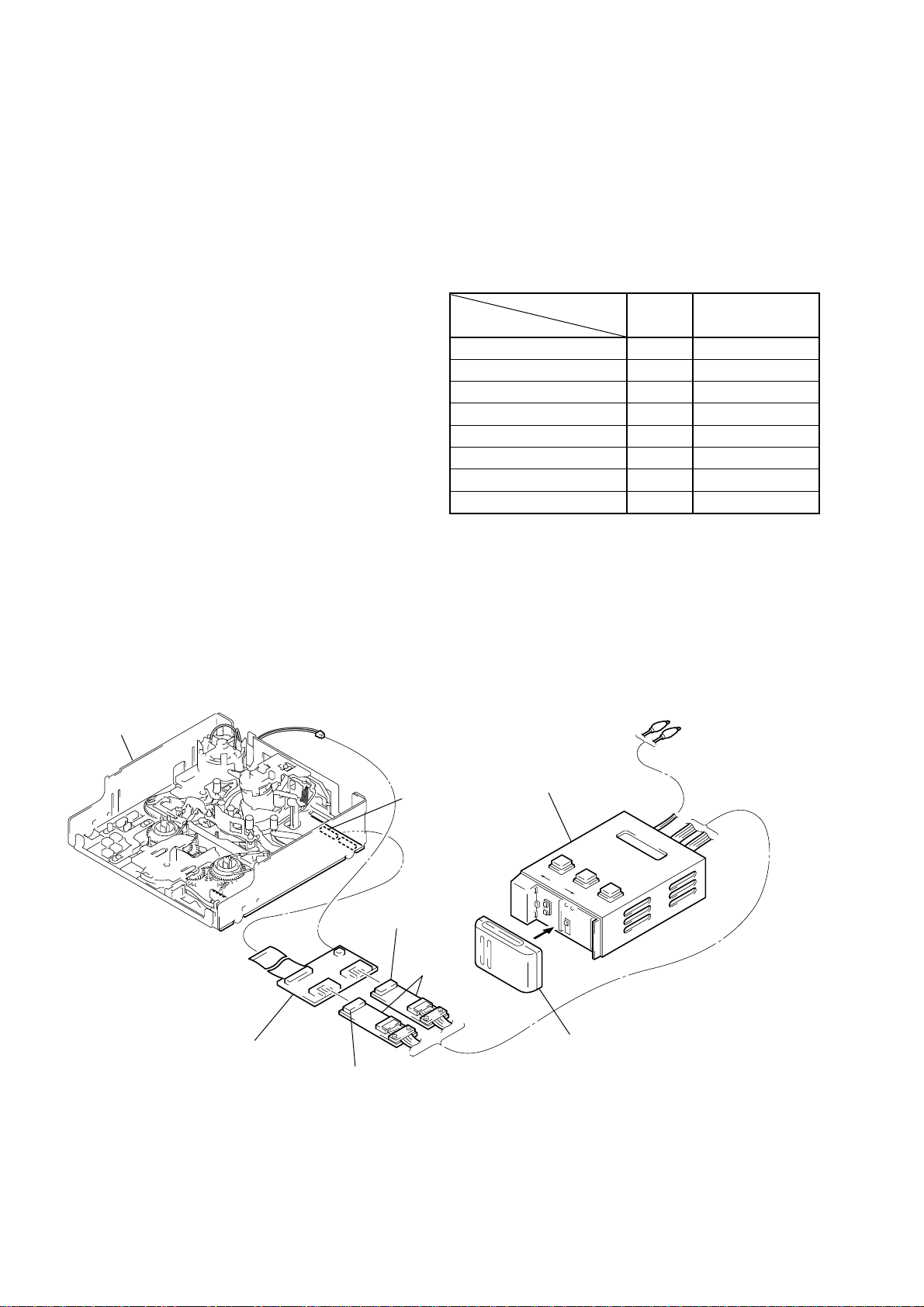
Note: When removing the MD-76 board, all the parts in the shaded
boxes ( ) of the chart need to be removed.
parts list”.
INFORMATION
Find the replacement parts in Section 5, “Repair parts list (exploded
views)” and attach or remove the parts in the follo wing order . When
replacing and re-attaching the parts, adjustments are sometimes
required. Follow the instructions of each item.
Note: Drawing numbers in each box of the chart refer to the numbers
START
— 3 —
1. PARTS REPLACEMENT AND PREPARATION FOR ADJUSTMENT
1-1. ASSEMBLY/DISASSEMBLY OF CASSETTE COMPARTMENT
For details on disassembling the mechanism deck (R mechanism), refer to the Service Manual of the main unit in which the R mechanism is
mounted.
Before attaching or removing the cassette compartment, check the position of “L cassette”.
Cassette compartment
(Remove in the direction of arrow
Positioning pin
A
Screw
A
.)
SL shifter
B
Bent portion
When attaching the cassette compartment,
move the reel selector slider in the direction of
B
arrow
to check the position of “L cassette”.
C
Tightening torque of cassette compartment
±
0.3432
0.0196N • m (3.5 ± 0.2 kg • cm)
Screw
SL shifter
Bent portion
Bent portion
selector slider should be
securely hooked on the
bent portion of the SL
shifter.
Positioning pin
When selecting a cassette position, be careful not to
touch the slider drive shaft because it can be easily
bent or broken.
Do not touch the slider drive shaft.
Select the desired cassette position by pressing
the claw position.
C
C
of the reel
Reel select slider
1-2. HOW T O LOAD/UNLOAD
[Using the regulated power supply]
Note: Make sure to remove the connector of the cam motor from the board
of the main unit and apply +5V current.
Cam motor
Loading : Apply positive polarity (+) of power supply to the gray wire
and negative polarity (–) of power supply to the white wire.
Unloading: Apply negative polarity (–) of power supply to the gray wire
and positive polarity (+) of power supply to the white wire.
White
Gray
Apply current from
the inlets of the connector.
[Manual: No cam motor]
Note: Remove the cam motor from the motor holder while referring to
“Information” on page 3.
Rotate the coupling gear by hand to load or unload.
[Rear side of chassis]
Coupling gear
Unloading
Loading
— 4 —
1-3. Service Jigs and Tools
J-1: Cleaning fluid
(9-919-573-01)
J-2: Wiping cloth
(7-741-900-53)
J-3: Super fine applicator
(made by NIPPON
APPLICATOR (P752D))
(J-2501-023-A)
J-4: Mirror (Small oval type)
(J-6080-840-A)
J-5: Screwdriver for tape path
(J-6082-026-A)
J-9: Mode Selector
(J-6082-282-B)
J-13:TG2/7 preset plate
(J-6082-459-B)
J-6: Tracking tape (XH2-1)
(NTSC/PAL)
(8-967-997-01)
J-10:FLOIL Grease (SG-941)
(7-622-601-39)
J-14:Relay board for tension
regulator adjustment
(J-6082-461-A)
J-7: Mini DV torque cassette
(J-6082-360-A)
J-11 Cassette refernce plate
(J-6082-330-A)
J-15:Mode selector conversion
board (R)
(J-6082-460-A)
J-8: Adjustment remote
commander
(RM-95 upgraded)(Note1)
(J-6082-053-B)
J-12:Reel reference plate
(J-6082-331-A)
J-16:Mode Selector
(Note2)
(J-6082-314-E)
ROM
J-17:
Board for tension regurator
adjustment
(J-6082-359-A)
Note1: If the micro processor IC in the adjustment remote commander is
Note 2: ROM for version upgrading to allow use of the mode selector II
not the new micro processor (UPD7503G-C56-12), the pages
cannot be switched. In this case, replace with the new micro
processor (8-759-148-35).
with the R mechanism.
— 5 —
1-4. About Mode Selector II
• About Mode Selector II
4-1. OUTLINE
This unit is a mechanism drive tool which supplements the
maintenance of each mechanism deck. Its functions are described
below.
1. Manual test
A mode which drives the motor only while the switch is ON. It
enables the operator to control the motor as desired.
2. Step test
A mode which drives the motor until the current condition detected
by the sensor changes to another condition. It enables the movements
made by the motor in each operation to be controlled while being
detected.
3. Auto test
A mode that checks if the mechanism operates normally according
to the condition shift table recorded in the unit for each mechanism
deck. All the conditions of the decks are checked through a series
of operations.
An error message is displayed and operations are stopped if incorrect
shifts and conditions are detected.
4-2. MECHANISM CONDITION (POSITION)
SHIFTING ORDER LIST
After selecting the mechanism deck, select one of the two test modes
other than the auto test, and press the RVS or FF button to specify
the mechanism state (position).
Code
A
0
0
1
1
1
1
1
B
1
0
0
0
0
1
1
MD name
C
1
1
1
0
1
1
0
D
1
1
1
1
0
0
1
1
2
3
4
5
6
7
R mechanism
ULE
DEW
LE
REW
FF
STOP
FWD / RVS
4-3. MODE SELECTOR II CONNECTION
Connector from the cam motor
R mechanism
Mode selector conversion board (R)
Connector (black) 6P
Alligator clip
Mode selector II
CN2
Connector (white) 6P
Relay boards
Battery of NP-55, 77, etc. (power supply)
— 6 —
2. PERIODIC CHECK
• Carry out the following maintenance and periodic checks not only to fully display the functions and performance of the set, but also for the
equipment and tape. After replacing, service the set as follows, regardless of the length of use.
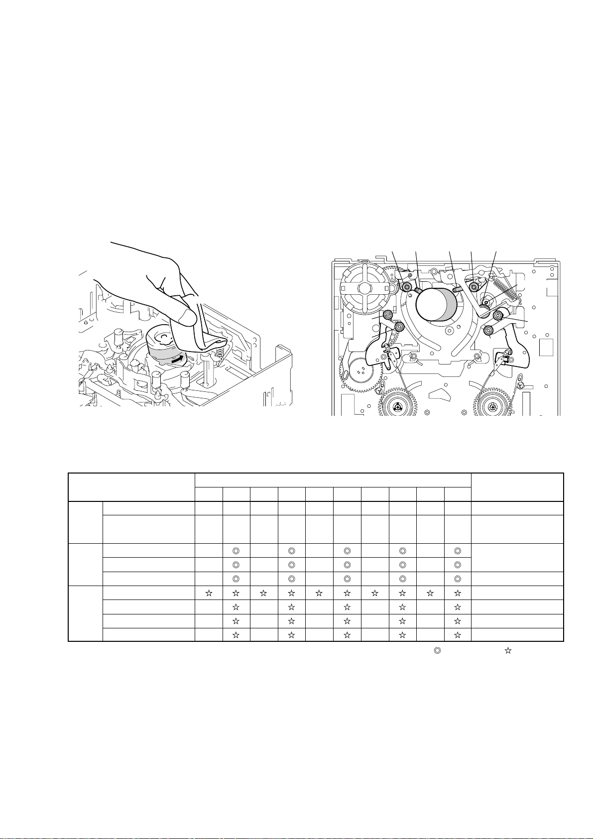
2-1. CLEANING OF ROTARY DRUM ASSEMBLY
1. Press a wiping cloth (J-1) moistened with cleaning fluid (J-2)
against the rotary drum assembly gently, and clean it while
rotating the rotary drum assembly slowly with your finger in
the counterclockwise direction.
Note: Do not rotate the motor on power or rotate the rotary drum assembly
in the clockwise direction with your finger. The head tip will also be
damaged if the wiping cloth is moved perpendicularly against it.
Therefore, be sure to follow the above instructions when cleaning
the rotary drum assembly.
Cleaning cloth
Rotary
drum assembly
2-2. CLEANING OF TAPE PATH SYSTEM
1. Clean the tape path systems (TG1 to TG8 and capstan) and the
lower drum using a super fine applicator (J-3) moistened with
cleaning fluid.
Note: Make sure that no oil or grease of the link mechanisms sticks to the
super file applicator (J-3).
Note: Do not use a applicator moistened with alcohol to the other guide
cleaning. But clean the pinch roller using alcohol.
TG 3 Pinch roller
TG 2
TG 1
TG 6TG 5TG 4
Capstan
TG 7
TG 8
2-3. PERIODIC CHECKS
Location of Maintenance
and Check
Cleaning of tape path surface
Cleaning and degaussing
of rotary drum assembly
Capstan (Bearing)
Driving
System
Performance
Confirmation
Note: When overhauling, refer to the checks above and replace parts.
Note: Greasing
Gear
Cam motor (worm block)
Abnormal noise
Back tension measurement
Brake system
FWD/RVS torque measurement
Always use the specified grease. If the viscosity differs, various
problems may occur.
(Use SG-941 for all parts of the R mechanism.)
Check the quantity of grease when installing the parts which is
needed to apply the grease. When replacing these parts, make sure
to apply the specified amount of grease.
500
a
a
–
–
–
–
–
–
1000
a
a
1500
a
a
–
–
–
–
–
–
2000
Hours of Use (H)
2500
a
a
a
a
–
–
–
–
–
–
3000
a
a
5000
4500
4000
3500
a
a
a
a
a
a
a
a
–
–
–
–
–
–
a
: Cleaning : Appling grease : Confirmation
–
–
–
–
–
–
Remarks
Be careful of the oil.
Be careful of the oil.
Make sure that no oil gets
on the tape path surface.
X-3946-702-1 (M902)
• FOIL (SG-941): Part No. 7-662-601-39
— 7 —
3. PARTS REPLACEMENT
• Precaution
For details on disassembling the cabinets, boards and other parts, refer to “Disassembly” of the Service Manual of each model. For details on
replacing parts (disassembly, assembly) of the mechanism deck, refer to “Information” on page 3.
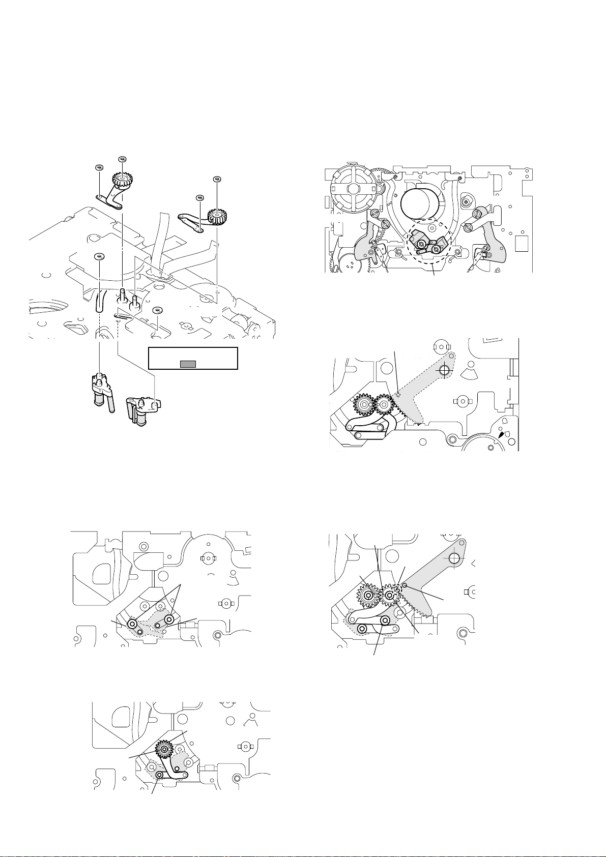
3-1. TAPE GUIDE 1/8 AND GUIDE GUARD
Disassembly/Assembly
When the tape guide 1/8 is replaced or attached, perform each
adjustment from Adjustment Start -2 of the flowc hart on page 22.
To attach or remove the tape guide, use the
screwdriver for the tape path (J-5). When
attaching the TG rollers, check the upward and
downward directions and attach them to the
chassis shaft.
Face the side of the
TG roller
The guide guard is fixed at each slit of the cassette
positioning shaft. To attach the guide guard, only
insert it into the right and left holes. To remove it,
use a pair of tweezers as shown in the figure
below.
deepest hole downward
and insert the roller into
the shaft.
Guide guard
[TG1 side]
(The components are the
same as on the TG8 side.)
Be careful not to touch the
tape guide ( part).
[TG8 side]
TG upper flange
TG roller
TG sleeve
TG ring
Compression coil
spring (TG)
Insert a pair of tweezers into the
clearance of the chassis to release
the lock of the slit.
Cassette positioning shafts
Lock of slit
3-2. TAPE GUIDE 2/7
Disassembly/Assembly
When the tape guide 2/7 is replaced or attached, perform each
adjustment from Adjustment Start -3 of the flowc hart on page 22.
To attach or remove the tape guide, use the
screwdriver for the tape path (J-5). When
attaching the TG rollers, check the upward and
downward directions and that the TG roller to be
attached to the TG7 side is exclusiv ely for the TG7
side. Then attach the TG rollers to the chassis
shaft.
TG2 arm block
Face the side of the deepest
hole downward and insert the
TG7 roller
roller into the shaft.
The lower flange of the TG7
roller is thicker than those of
the TG1, 2, and 8 rollers.
[TG2 side]
TG upper flange
TG roller
TG sleeve
TG ring
Compression coil
spring (TG)
[TG7 side]
TG upper flange
TG7 roller (Note that the shape is
different from that of the other rollers.)
TG sleeve
TG ring
Compression coil spring (TG)
Be careful not to touch the
tape guide ( part).
— 8 —
TG7 arm block
3-3. CAPSTAN COVER
Do not fasten
this screw.
CN 3
Screw
2
Fasten the screws
in order of 1, 2, 3.
Reel motor
Screw
1
Screw
3
Tightening torque of reel motor
0.0686 ± 0.0098 N • m (0.7 ± 0.1 kg • cm)
After inserting the flexible board
of the reel motor into CN3, attach
the reel motor and lock CN3.
3-4. REEL MOTOR
Disassembly/Assembly
Screw
Capstan cover
Tightening torque of capstan cover
0.3432
±
0.0196 N • m (3.5 ± 0.2 kg • cm)
Claw
Pass the two flexible boards
1
of the drum assembly through
the hole.
Disassembly/Assembly
2
Insert the claw into the long hole
of the chassis and fix the cover
with the screw.
3-5. FL MOTOR ASSEMBLY, GEAR A, GEAR B AND GEAR CD ASSEMBLY
Disassembly/Assembly
FL motor assembly
Positioning bosses
Gear A
Gear CD assembly
Gear B
Hole
C
D
Hole
Hole
Remove the claws of the FL motor assembly from hole A and hole
B
and remove the FL motor assembly. Then, remove each gear, etc.
T o attach them, after attaching the gears, etc. to the FL motor assembly
and hook the positioning bosses of the FL motor block on holes
and D then fit the two claws in each hole A and B.
Apply grease
A
(half size of one grain of rice).
C
The worm gears are attached inside the
FL motor assembly . When attaching the FL
motor assembly, apply grease there.
Hole
B
— 9 —
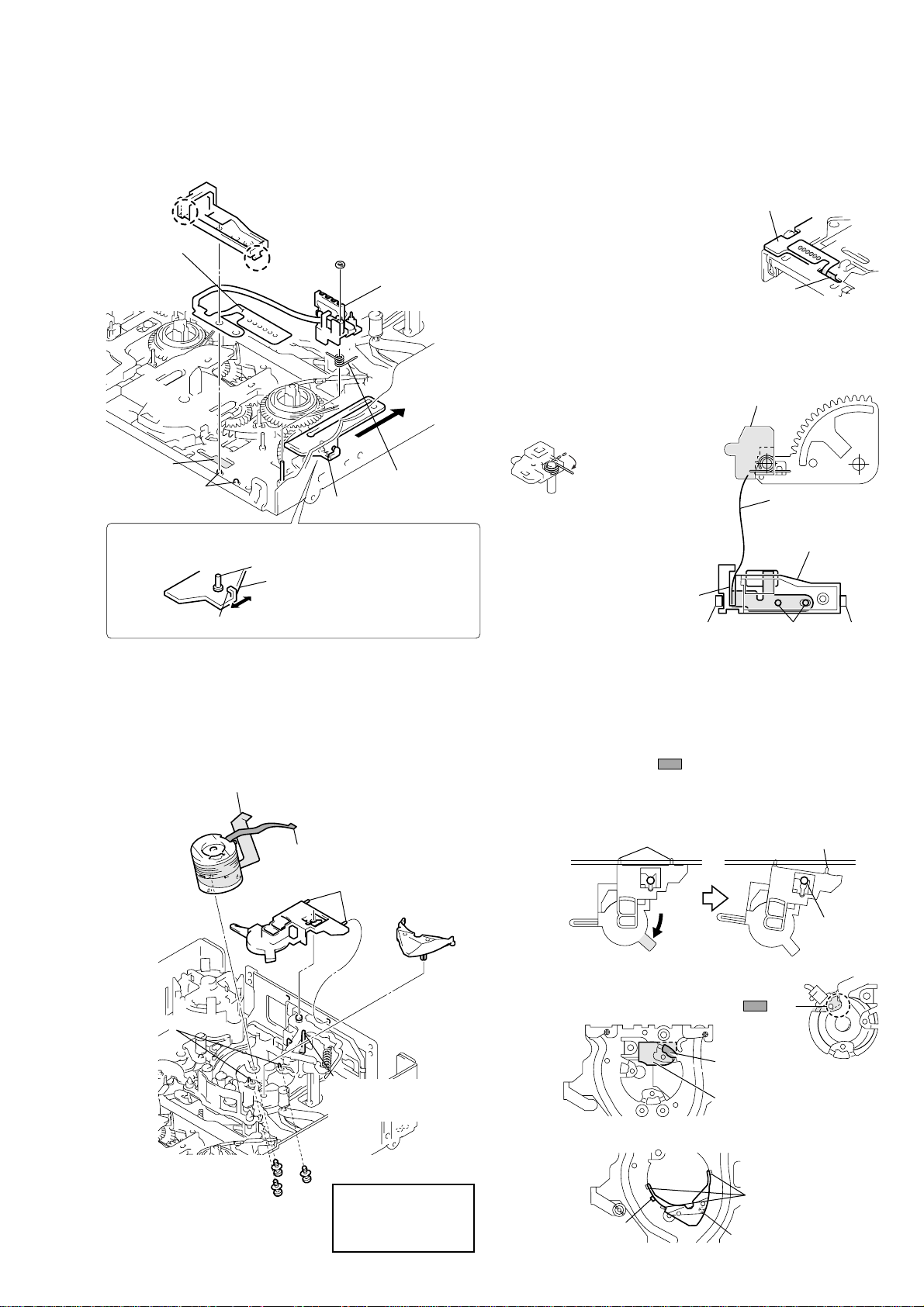
3-6. GL ARM S ASSEMBLY, GL ARM T ASSEMBLY, COASTER S ASSEMBLY AND
)
COASTER T ASSEMBL Y
Disassembly: Remove the parts in order of 1,2,3,4,5,6,7,8,9,0
For the disassembling and assembling procedures of the GL gear,
GL helical torsion spring, etc., refer to page 20.
Stop washer
Coater stop
washer
4
Stop washer
Move the TG2/7 arms to the loading position with the regulated power
supply or by hand while referring to page 4. Each coaster assembly
must be in the unloading position.
5
GL arm T
assembly
6
Coater stop
washer
2
1
GL arm S
assembly
TG2 arm
3
Coaster stopper
9
Unloading position
TG7 arm
7
Coaster stopper
Do not touch the tape
Coaster T
0
assembly
Assembly
1 Attach the coaster S/T assembly to the chassis with a new
coaster stopper while being careful not to touch the tape guide.
Do the work while holding the drum side of each coaster.
guide ( part).
8
Coaster S assembly
Coaster stoppers
With consideration for future assembly, check from the rear of the
chassis that the phase of the loading arm assy is aligned.
The phase must be aligned
with the hole of the chassis.
Loading arm assy
3 Attach the GL arm S assembly while checking the phase of
each part. Fix the stop washers at the correct position, using
new stop washers.
Loading arm assy
Hole
B
Hole
Hole
A
C
Coaster T assembly
Coaster S assembly
2 Attach the GL arm T assembly. Fix the stop washers in the
correct position, using new stop washers.
GL arm T assembly
Stop washer
(The stop hole is smaller.)
Coaster stop washer
(The stop hole is larger.)
— 10 —
Hole
D
Stop washer
(The stop hole is smaller.
Coaster stop washer
(The stop hole is larger.)
Check each phase adjustment while referring to the above
figure.
Hole A of the GL gear T and hole B of the GL gear S must
face each other. Hole D of the loading arm assy must be aligned
with the hole of the chassis, and the endmost gear tooth of the
loading arm assy must face toward hole C of the GL gear S.
3-7. MIC BASE GUIDE, MIC BASE ASSEMBLY AND MIC BASE SPRING
t
Pins
Pin
Center shaft
Be careful that the 7P flexible board
does not interfere with the part.
Disassembly/Assembly
For the disassembling and assembling procedures of the components
of the MIC base assembly, refer to page 20.
Claw
FP-104 flexible
board
(Remove the
six solders.)
MIC base guide
Claw
Stop washer
(Do not reuse.)
MIC base
assembly
Remove the six solders on the FP-104 flexible board from
the rear of the chassis. P ass the flexib le board through hole
A
and pull it out of the front side of the chassis while being
careful not to damage it. T o attach the fle xible board, perform
the steps of disassembly in reverse order.
Six solders
Temperature of tip
of soldering iron : 350
Hold time : one second or shorter
Move the reel selector slider in the direction of arrow
and attach the MIC base assembly at the position of “S
cassette”. For the assembly of the MIC base spr ing, refer
to the figure.
±
20 °C
MD-76 board
A
Hole
B
Note: Do not hold the shaft when
B
Hole
A
Positioning pins
When selecting a cassette position, be careful not to touch the
slider drive shaft because it can be easily bent or broken.
Do not touch the slider drive shaft.
Reel select slider
Select the desired cassette position by pressing the claw position.
MIC base spring
Reel selector slider
When attaching the MIC base guide,
lock the positioning pins, claw C,
and claw D in this order. Route the
flexible board into the clearance of
the MIC base guide.
3-8. DRUM CAP, DRUM ASSEMBLY AND TAPE SUPPORT
Disassembly: Remove them in order of 1,2,3
For the disassembly and assembly procedures of the components of
the drum assembly, refer to page 21.
Flexible board (10P)
Assembly: Attach the parts while referring to the
(After assembling, adjust the tape path while referring to page 22
and thereafter.)
selecting the reels.
Insert the side of the
shorter spring into the
hole of the holder and
hook the side of the
longer spring.
Clearance
MIC base assembly
Claw
D
FP-104
flexible board
MIC base guide
Pins
Claw
disassembly procedure and the figure below.
Assembly and disassembly of the drum assembly
When pulling the part in the direction of the arrow, the
claw is removed from the center shaft, then the right pin
and the drum cap are removed as shown in the figure on
the right. To attach the drum assembly, perform the
disassembly steps in reverse order.
C
Drum
assembly
3
Drum reference pins
Drum fixing screw assembly
(Fasten the screws in order
Drum cap
3
1
Flexible board (7P)
Positioning pins
1
Be careful not to remove
this together with the drum
cap.
2
2
1, 2, 3
Tightening torque of
drum assembly
0.02941
.)
(0.3
Tape suppor
4
±
0.0049 N • m
±
0.05 kg • cm)
— 11 —
Assembly and disassembly of the drum assembly
Insertion hole of
flexible board (7P)
Insertion hole of
flexible board (10P)
Assembly and disassembly of the tape support
The claws are
hooked under
the sub-chassis.
The claw is hooked
on the sub-chassis.
Positioning pin
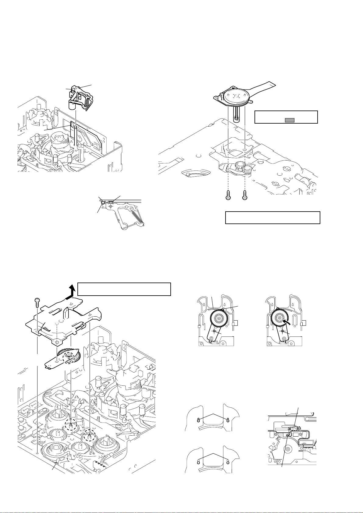
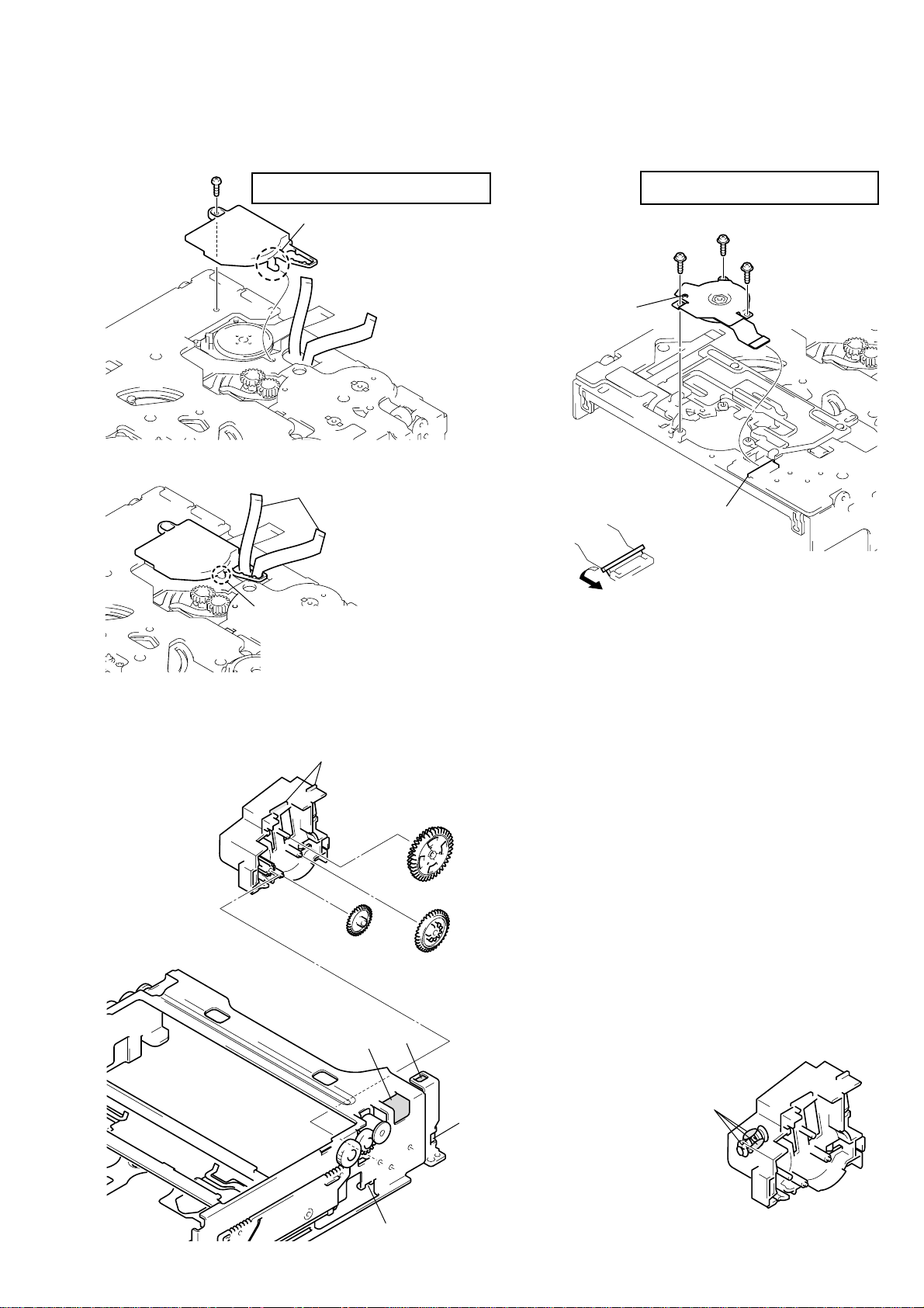
3-9. PINCH ARM ASSEMBLY
d
y
3-10. CAPSTAN MOTOR
Disassembly/Assembly
For the disassembling and assembling procedures of the tape retainer
and compression coil spring (tape retainer), refer to page 21.
Roller
Roller
B
Claw
Push roller A into the
groove as shown in the
figure. Insert roller B into
the claw. To remove the
pinch arm assembly, pull
out the pinch arm upward
while pushing the claw.
Roller
A
Pinch arm assembl
Claw
B
Roller
A
Disassembly/Assembly
(After assembling, adjust the tape path from page 22.)
Capstan motor
Be careful not to touch the
motor shaft ( part).
Screw
Tightening torque of capstan motor
0.1961
±
0.0196 N • m (2.0 ± 0.2 kg • cm)
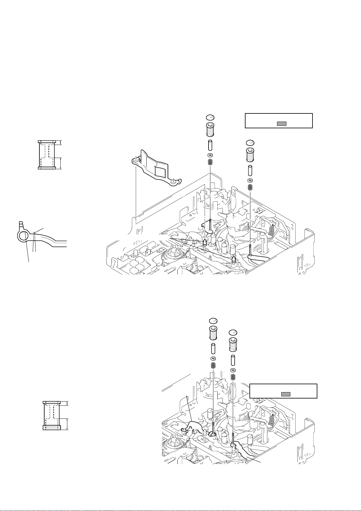
3-11. PENDULUM RETAINER AND PENDULUM ARM ASSEMBLY
Disassembly: Remove them in order of 1,2,3
(To attach them, perform the disassembly steps in reverse order.)
Tightening torque of pendulum retainer
1
Screw
Pendulum arm
assembly
3
Shaft
Shaft
Shaft
B
0.3432
A
±
0.0196 N • m (3.5 ± 0.2 kg • cm)
2
Pendulum retainer
(Remove in the direction
of the arrow.)
Shaft
B
Notes during assembly
When assembling or disassembling the pendulum arm assembly,
be careful of the following.
Insert tip
arm into hole
retainer and insert the pendulum
into shaft
Attach the pendulum retainer to shaft B. Be careful of the positions
of the pendulum stopper at the rear of the chassis and shaft A of the
pendulum arm.
[Rear side of pendulum retainer]
Hole
E
Shaft
D
of the pendulum
E
of the pendulum
C
.
Shafts
B
Can be removed.
D
F
Shaft
C
Slide the pendulum arm in
the direction of arrow
attach it to the chassis.
Pendulum stopper
C
F
an
Positioning boss
— 12 —
Shafts
B
Cannot be removed.
Shaft
A
of the pendulum
must be in this position.
 Loading...