

Page 1

4-460-309-13 (1)
LCD Color View Finder
Operating Instructions
Before operating the unit, please read this manual thoroughly
and retain it for future reference.
DVF-L700
© 2013 Sony Corporation
Page 2

Table of Contents
Overview ......................................................3
Usage Notes.................................................3
Parts Identification......................................4
Attaching the Viewfinder to a Camera.......6
Detaching the Viewfinder ..........................7
Adjusting the Position ................................8
Adjusting the Display..................................8
Error Messages ...........................................9
Cleaning the Screen....................................9
Specifications............................................10
Table of Contents
2
Page 3

Overview
Usage Notes
The DVF-L700 is a 7.0-inch color LCD viewfinder.
This unit has the following features.
High resolution and wide visual angle
The viewfinder uses a 7.0-inch Full HD resolution LCD
panel for a resolution of 1920 × 1080 and a wide visual
angle.
Stable picture
The LCD screen provides stable images without
distortion, regardless of display’s brightness.
HIGH BRIGHT function
The ability to increase the brightness instantly improves
visibility outdoors.
FOCUS MAG function
You can magnify the height and width of the image (x2)
for easier focus adjustment.
False color function
Display signal levels using different colors. When you
use the false color function, image signals are displayed
in black and white, and colors are added based on the
signal levels.
Tally indicator
The viewfinder is equipped with a single tally indicator
(red) that lights in response to a tally signal.
Place of use
When using the viewfinder in low temperature
environments, dynamic resolution levels may decrease
during the period immediately after you turn on the
power.
Condensation
If the unit is suddenly taken from a cold to a warm
location, or if ambient temperature suddenly rises,
moisture may form on the outer surface of the unit and/or
inside of the unit. This is known as condensation. If
condensation occurs, turn off the unit and wait until the
condensation clears before operating the unit. Operating
the unit while condensation is present may damage the
unit.
LCD panel
The LCD panel fitted to this unit is manufactured with
high precision technology, giving a functioning pixel
ratio of at least 99.99%. Thus a very small proportion of
pixels may be “stuck”, either always off (black), always
on (red, green, or blue), or flashing. In addition, over a
long period of use, because of the physical characteristics
of the liquid crystal display, such “stuck” pixels may
appear spontaneously. These problems are not a
malfunction.
Flexible operability
The three joints of the supplied flexible arm can be locked
via a single knob, allowing you to adjust the position of
the viewfinder for comfortable operation.
LCD image display
• Due to the physical characteristics of LCD panels, there
may be a decrease in brightness or change in color
temperature over a long period of use. These problems
are not a malfunction.
In addition, these occurrences will not affect recorded
data.
• If you leave the viewfinder displaying a still image for
a long time, an afterimage may appear on the screen.
Turn the power off if the viewfinder is not to be used for
an extended period of time.
Maintenance
• Use a dust blower to remove dust from the screen.
• Do not use solvents such as thinner to clean the screen.
Overview / Usage Notes
3
Page 4
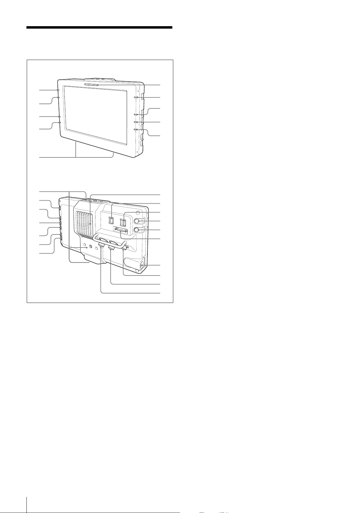
f Ventilation inlet
w
w
Parts Identification
g POWER indicator
Lights green when power is being supplied.
Front
h INPUT indicator
Lights green when there is a signal input. The indicator
0
9
8
7
1
2
3
4
5
blinks green when the signal format is not supported.
i SPARE indicator
Lights orange during false color display.
j FOCUS MAG (magnified display) indicator
Lights orange during magnified display.
k Ventilation outlet
6
l INPUT SELECT switch
Switches the input signal.
Rear
VF: Inputs signals from the VF connector (VF mode).
SDI: Inputs signals from the SDI IN connector (monitor
wh
wg
wf
wd
ws
wa
j
qa
qs
qd
qf
qg
qh
qj
qk
ql
;
mode).
m TALLY DIMMER switch
Allows you to adjust the tally indicator’s brightness.
Set this to OFF when you are not using the tally indicator.
HIGH: Increases the brightness.
LOW: Decreases the brightness.
OFF: Turns the indicator off.
n FOCUS MAG (magnified display) button
Magnifies the height and width of the image (x2) for
easier focus adjustment. This does not affect the camera’s
output signal.
The FOCUS MAG indicator lights during magnified
display.
The display switches between magnified display and
a Tally indicator
Lights or blinks red or turns off according to the situation.
Lit: The camera/camcorder is recording.
Blinking: An error or warning has occurred.
normal display with each press of the button.
o SPARE button
When using the PMW-F5/F55 (version 2.00), this allows
you to switch to false color display. This does not affect
For details on the status of the indicator, refer to the
operating instructions for your camera/camcorder.
the camera’s output signal.
The SPARE indicator lights during false color display.
The display switches between false color display and
b HIGH BRIGHT (high-brightness display)
indicator
Lights yellow during high-brightness display.
c BRIGHT adjustment indicator
Lights orange during brightness adjustment.
normal display with each press of the button.
During VF mode, images are displayed according to the
false color configured on the camera.
During monitor mode, images are displayed in an SLog2-compatible format.
During false color display, the PEAKING button is
disabled and the peaking cannot be adjusted.
d CONTRAST adjustment indicator
Lights orange during contrast adjustment.
e PEAKING adjustment indicator
Lights orange during peaking adjustment.
Parts Identification
4
p VF connector (26-pin rectangular type)
When using VF mode, connect this to the VF connector
on the camera using the supplied VF connection cable.
q POWER switch
Sets the power of the LCD panel to ON or SAVE.
Page 5

r DC IN connector
When using monitor mode, connect this to an external
power supply (10.5 V to 17.0 V DC) using the supplied
power cable (with “STRAIGHT CABLE” label). When
using the PMW-F5/F55, connect to the DC OUT
connector on the battery adaptor.
The power cable (with “STRAIGHT CABLE” label) is
not necessary when using VF mode, as power is supplied
via the VF connector.
Note
Use the power cable supplied with this unit.
The power cables (without “STRAIGHT CABLE”
labels) supplied with units with serial numbers X00001 to
X00999 are crossover cables. Therefore, they cannot be
used with units with other serial numbers.
s MONITOR OUT connector (BNC type)
Outputs the same signal that is input to SDI IN.
Notes
• The MONITOR OUT output is only output when the
power of the unit is set to ON. There is not output when
power is not being supplied to the DC IN connector, or
when power is being supplied but the POWER switch
is set to SAVE.
• The MONITOR OUT output does not meet the output
standards of a main line channel.
z HIGH BRIGHT (high-brightness display)
button
Brightens the display to improve visibility when shooting
outdoors. This does not affect the camera’s output signal.
The HIGH BRIGHT indicator lights during highbrightness display.
The display switches between high-brightness display
and normal display with each press of the button.
During high-brightness display, the CONTRAST button
is disabled and the contrast cannot be adjusted.
wjFlexible arm attachment points
Attach the supplied flexible arm here.
Note
Do not block the ventilation inlet and outlet. Doing so
may result in internal overheating and malfunctions.
t SDI IN connector (BNC type)
When using monitor mode, connect this to the SDI OUT
connector on the camera using a BNC cable.
For details on supported formats, see “Specifications”
(page 10).
u – (minus) button
Use this after pressing the BRIGHT, CONTRAST, or
PEAKING button to change the respective value.
v + (plus) button
Use this after pressing the BRIGHT, CONTRAST, or
PEAKING button to change the respective value.
w PEAKING adjustment button
Allows you to emphasize the outlines in the image. This
does not affect the camera’s output signal.
x CONTRAST adjustment button
Allows you to adjust the contrast in the image. This does
not affect the camera’s output signal.
y BRIGHT adjustment button
Allows you to adjust the brightness in the image. This
does not affect the camera’s output signal.
Parts Identification
5
Page 6
Attaching the Viewfinder to a Camera
Note
Depending on the version of your PMW-F5/F55, an
image may not be displayed.
In such cases, contact a Sony service representative.
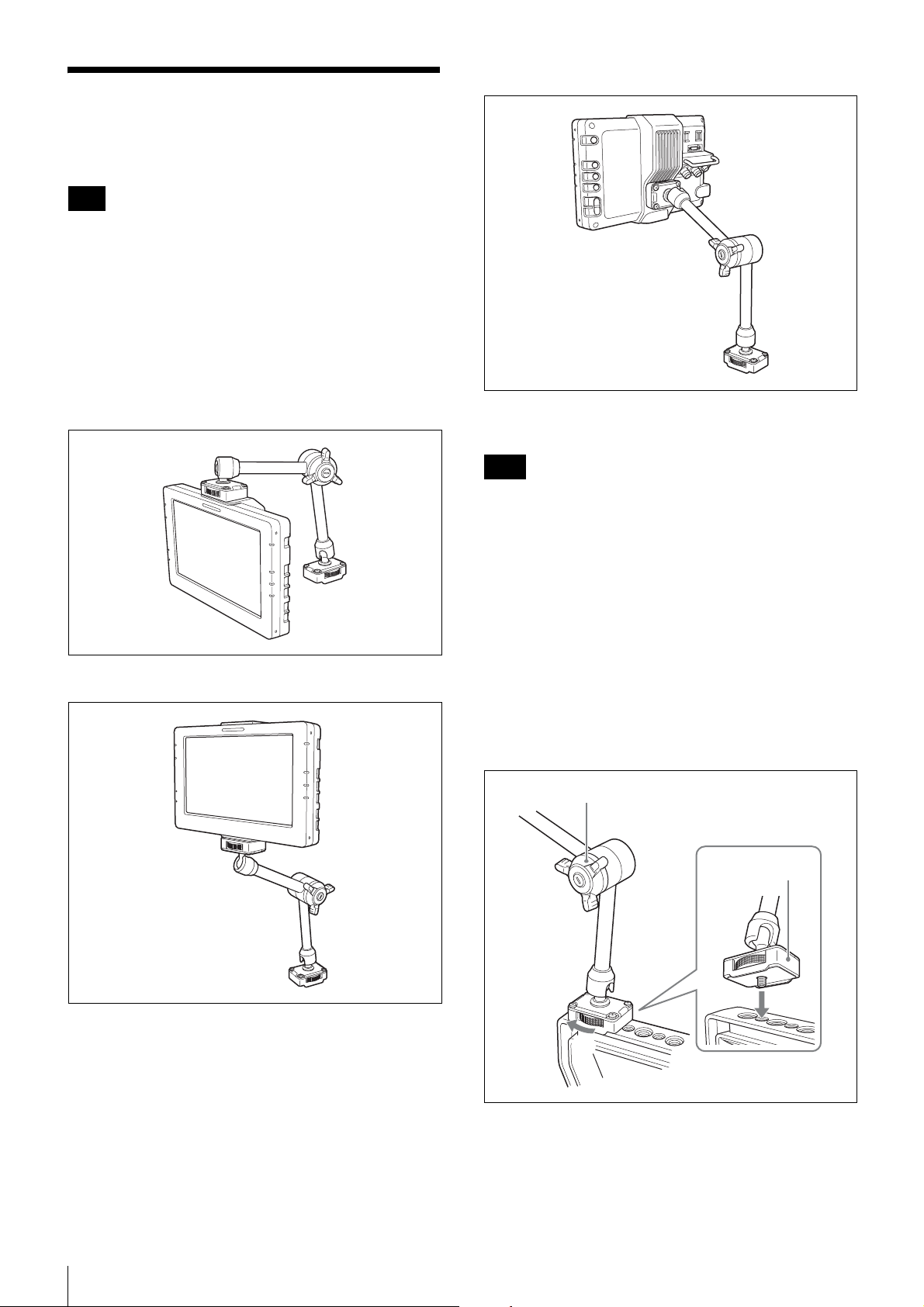
Attach this unit to the camera using the supplied flexible
arm.
This unit has a total of three flexible arm attachment
points at the top, bottom, and rear of the unit. Select an
attachment point based on your intended use.
Rear attachment point
Top attachment point
Bottom attachment point
This section describes how to attach the flexible arm to
the top of the unit as an example.
Notes
• Hold both the viewfinder and the flexible arm firmly
when performing attachment or detachment.
In addition, the flexible arm may move at its joints if the
arm lock knob is loose. Take care not to drop the
viewfinder and flexible arm.
• Fixing screws are located on both ends of the flexible
arm. Confirm the camera end and the viewfinder end,
and perform attachment using the proper ends.
Camera attachment point: Includes edges that fit the
camera’s handle.
Viewfinder attachment point: Includes a positioning
pin.
1
Attach the flexible arm to the camera.
Arm lock knob
Camera
attachment point
Attaching the Viewfinder to a Camera
6
1
2
1 Align the screw on the flexible arm’s camera
attachment point with screw hole (1/4-20UNC) on
top of the camera’s handle.
Make sure the camera attachment point is oriented
correctly in relation to the handle.
Page 7
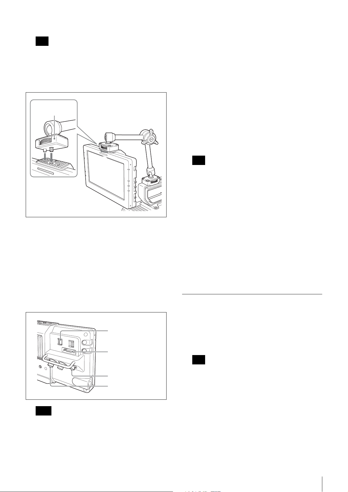
2 Secure the fixing screw.
Note
Be sure to use a 1/4-inch screw hole. Using a screw
hole of a different size may result in the flexible arm
falling off and causing injuries.
2
Attach the viewfinder to the flexible arm.
Viewfinder
attachment point
1
2
• Fully insert the cable connectors into the
connectors and make sure they are secure. If the
connector is not firmly connected, the image may
be distorted and the tally indicator may not light
properly.
For use in VF mode
1 Use the VF connection cable (supplied) to connect
the viewfinder’s VF connector to the camera’s VF
connector.
Connect the straight connector to the viewfinder’s
VF connector and the angle connector to the
camera’s VF connector.
Verify the orientations of the connectors, and insert
them until they click into place.
2 Set the INPUT SELECT switch to the VF position.
Note
Be sure to check the shape of the VF connection
cable’s connector, and insert it in the proper
orientation.
1 Align the screw and positioning pin on the flexible
arm’s viewfinder attachment point with the screw
hole and positioning hole on the viewfinder.
The flexible arm attachment point on the
viewfinder has two positioning holes to the left and
right of the screw hole. Select the appropriate hole
based on your intended use.
2 Secure the fixing screw.
3
Connect the cables.
INPUT SELECT switch
VF connector
DC IN connector
For use in monitor mode
1 Use a BNC cable to connect the viewfinder’s SDI
IN connector to the camera’s SDI OUT connector.
2 Use the power cable (with “STRAIGHT CABLE”
label) (supplied) to connect the viewfinder’s DC
IN connector to an external power supply.
When using the PMW-F5/F55, connect to the DC
OUT connector on the battery adaptor.
3 Set the INPUT SELECT switch to the SDI
position.
Detaching the Viewfinder
1
Disconnect the cables connected to the viewfinder.
When disconnecting the VF connection cable, pull
the connector straight out while pressing the lock
release buttons on both sides of the connector.
Note
Forcibly pulling the connector without pressing the
lock release buttons may damage the connector.
SDI IN connector
Notes
• Always turn off the camera before connecting the
cables to the connectors on the camera. If you make
the connection while the camera is on, the
viewfinder may not function properly.
2
Loosen the fixing screw on the flexible arm’s
viewfinder attachment point, and detach the
viewfinder from the flexible arm.
3
Loosen the fixing screw on the flexible arm’s camera
attachment point, and detach the flexible arm from
the camera.
Attaching the Viewfinder to a Camera
7
Page 8
Adjusting the Position
Adjusting the Display
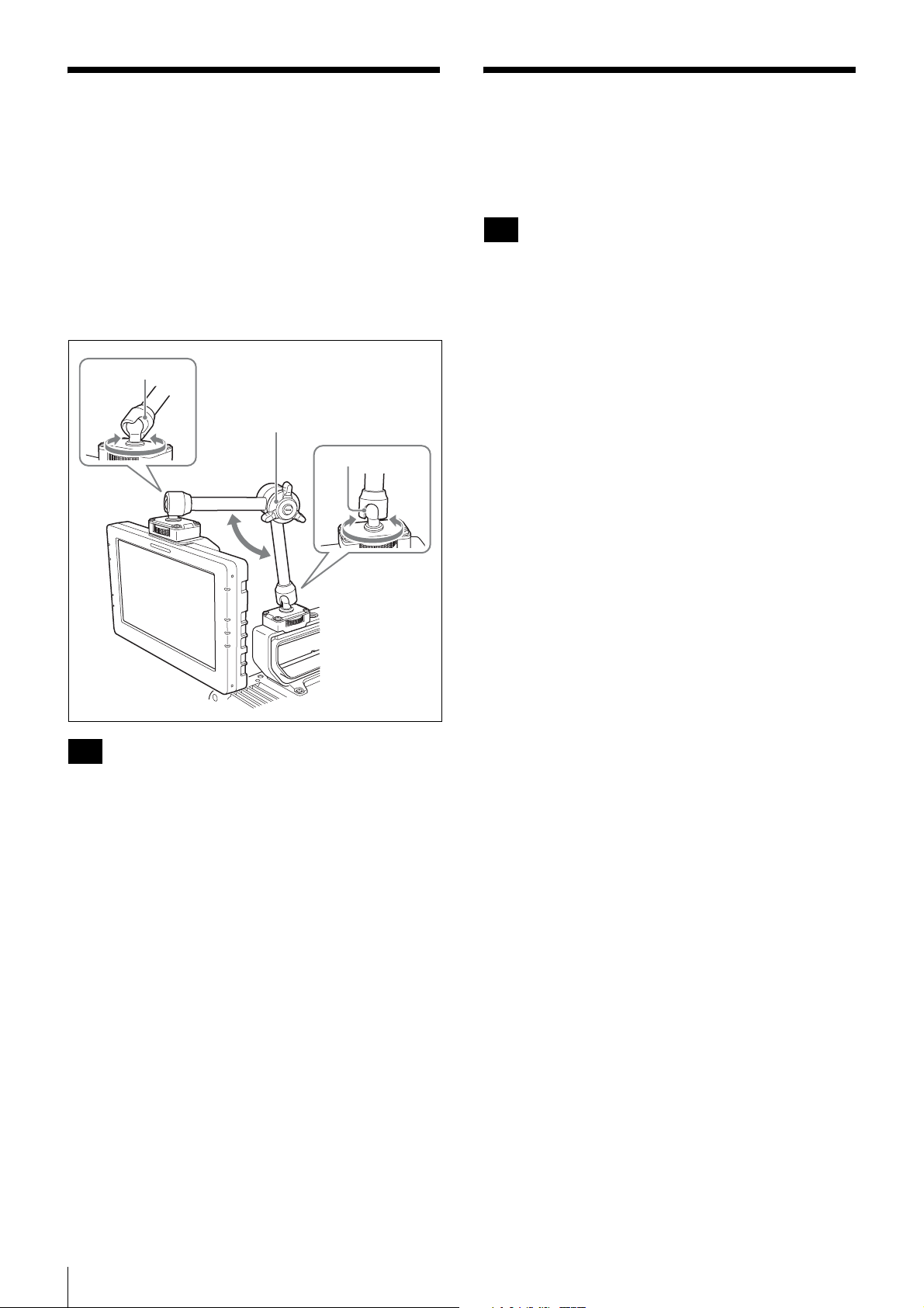
You can adjust the height, orientation, and angle of the
viewfinder via the flexible arm’s three joints.
Center joint
Allows you to adjust the height by changing the angle of
the arm’s two poles.
Top and bottom joints (ball type)
Allows you to change the orientation via rotation, or tilt
the arm in the direction of the notches.
Notch
Arm lock knob
Notch
You can adjust the brightness, contrast, and peaking of
the display using the BRIGHT, CONTRAST, and
PEAKING buttons.
Note
When using VF mode, changing the peaking value with
the PEAKING button will not affect the display image
unless the peaking setting on the camera is enabled.
Example: Adjusting the contrast
1
Press the CONTRAST button.
The CONTRAST indicator lights, and adjustment is
enabled.
2
Change the values using the – and + buttons.
The display image changes according to the changes.
To restore the default values, press the – and
+ buttons simultaneously.
3
When you finish configuration, press the
CONTRAST button again.
Note
Hold the viewfinder firmly when loosening the arm lock
knob to prevent it from dropping.
1
Turn the flexible arm’s arm lock knob in the opposite
direction of LOCK to loosen it.
2
Adjust the position.
3
Turn the arm lock knob in the LOCK direction to lock
it into place.
The three joints of the flexible arm will be locked into
place.
The CONTRAST indicator turns off.
Adjusting the Position / Adjusting the Display
8
Page 9
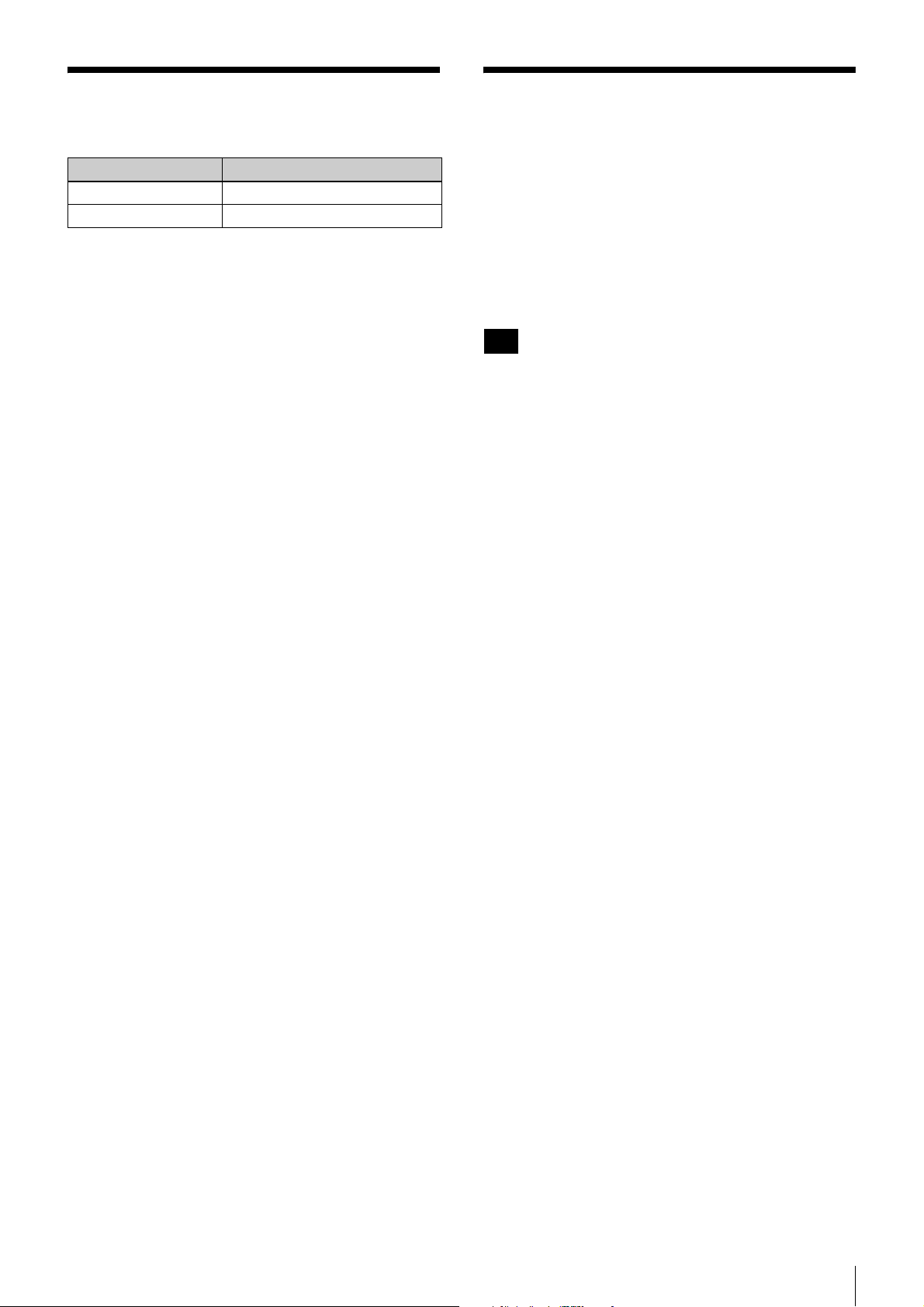
Error Messages
Cleaning the Screen
Display Description
VF TEMP HIGH Temperature error
DEVICE ERROR Device error other than the above
When cleaning the viewfinder’s screen, remove the
viewfinder from the camera, and take care not to damage
the components.
For details on how to remove the viewfinder from the
camera, see “Detaching the Viewfinder” (page 7).
Removing dust from the surface of the screen
Use a dust blower.
Note
Do not use thinner or other solvents.
After use in harsh environments
Be sure to perform the following maintenance after using
the viewfinder at dusty locations, beaches, hot springs, or
other harsh environments.
• Use an airbrush to carefully remove any dust or sand
from inside the viewfinder.
• Clean the contacts of the connectors.
• After performing the above maintenance, perform a
basic operation test and check that the viewfinder is
functioning properly.
Error Messages / Cleaning the Screen
9
Page 10
Specifications
General
Power supply
10.5 V to 17.0 V DC
(supplied from the camera or external source)
Power consumption
11.5 W (SDI connection, HIGH BRIGHT disabled)
18.5 W (SDI connection, HIGH BRIGHT enabled)
Operating temperature
0 °C to 40 °C (32 °F to 104 °F)
Storage temperature
–20 °C to +60 °C (–4 °F to +140 °F)
Mass
Approx. 700 g (1 lb 8.7 oz)
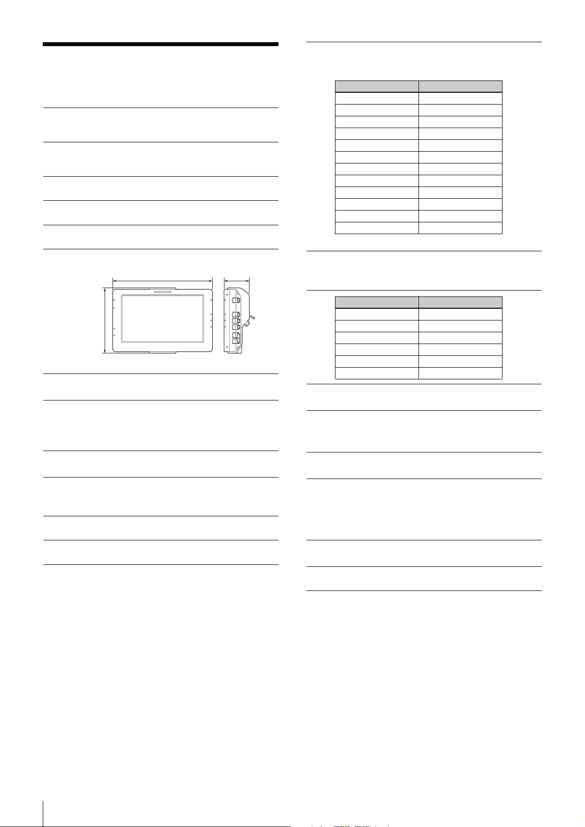
Dimensions
3
/4) 52 (2 1/8)
194 (7
127 (5)
Unit: mm (inches)
Supported formats (during HD-SDI connection)
Total number of scanning lines: 1125
Number of effective scanning lines: 1080
Format Frame rate
1080/59.94P 59.94
1080/50P 50
1080/29.97P 29.97
1080/25P 25
1080/24P 24
1080/23.98P 23.98
1080/59.94i 29.97
1080/50i 25
1080/29.97PsF 29.97
1080/25PsF 25
1080/24PsF 24
1080/23.98PsF 23.98
(Horizontal resolutions of 2048 are not supported.)
Colors and signal levels displayed for false color
(during S-Log2)
Color display Signal level
Red 105.4% or higher
Yellow 102.4% to 105.4%
Pink 41.3% to 45.3%
Green 30.3% to 34.3%
Blue 2.5% to 4.0%
Purple 0% to 2.5%
LCD
7.0-inch color TFT transmissive LCD
Display area
155.5 × 87.5 mm (6 1/8 × 3 1/2 inches) (H/V, 16:9
aspect ratio)
Performance
Brightness
Normal: 300 cd/m2 (typical)
HIGH BRIGHT mode: 850 cd/m
Resolution
1920 × 1080
Color temperature
D65
2
(typical)
I/O interface
VF: 26-pin rectangular type (1)
SDI IN: BNC type (1)
MONITOR OUT: BNC type (1)
DC IN: 4-pin (1), 10.5 V to 17.0 V DC
Supplied accessories
Before Using this Unit (1)
Operating Instructions (CD-ROM) (1)
Power cable (4-pin, with “STRAIGHT CABLE” label) (1)
VF connection cable (26-pin) (1)
Flexible arm (1)
Warranty (1)
Related accessories
Solid-State Memory Camcorder
PMW-F5, PMW-F55
Design and specifications are subject to change without
notice.
10
Specifications
Page 11

Notes
• Always verify that the unit is operating properly
before use. SONY WILL NOT BE LIABLE FOR
DAMAGES OF ANY KIND INCLUDING, BUT
NOT LIMITED TO, COMPENSATION OR
REIMBURSEMENT ON ACCOUNT OF THE
LOSS OF PRESENT OR PROSPECTIVE PROFITS
DUE TO FAILURE OF THIS UNIT, EITHER
DURING THE WARRANTY PERIOD OR AFTER
EXPIRATION OF THE WARRANTY, OR FOR
ANY OTHER REASON WHATSOEVER.
• SONY WILL NOT BE LIABLE FOR CLAIMS OF
ANY KIND MADE BY USERS OF THIS UNIT OR
MADE BY THIRD PARTIES.
• SONY WILL NOT BE LIABLE FOR THE
TERMINATION OR DISCONTINUATION OF
ANY SERVICES RELATED TO THIS UNIT THAT
MAY RESULT DUE TO CIRCUMSTANCES OF
ANY KIND.
Specifications
11
Page 12

Sony Corporation
 Loading...