

SONY DV 515 Service Manual
STANDBY
STANDBY/ON
DVD PLAYER
DV-515
SERVICE GUIDE
10KEY OPERATION
+10
TITLE
VIRTUAL DOLBY
SURROND
1
627384950
0
FL OFF
14¡¢
7
£¥8
ORDER NO.
RRV2004
CONTENTS
1. CIRCUIT DESCRIPTION
2. TEST MODE
3. ERROR CODE
.........................................................
....................................................
4. IC INFORMATION
PIONEER ELECTRONIC CORPORATION 4-1, Meguro 1-Chome, Meguro-ku, Tokyo 153-8654, Japan
PIONEER ELECTRONICS SERVICE, INC. P.O. Box 1760, Long Beach, CA 90801-1760, U.S.A.
PIONEER ELECTRONIC (EUROPE) N.V. Haven 1087, Keetberglaan 1, 9120 Melsele, Belgium
PIONEER ELECTRONICS ASIACENTRE PTE. LTD. 253 Alexandra Road, #04-01, Singapore 159936
c
PIONEER ELECTRONIC CORPORATION 1999
......................................
..............................................
2
7
15
19
T – IZM MAR. 1999 Printed in Japan

DV-515
1. CIRCUIT DESCRIPTION
1.1 BLOCK DIAGRAM
CODE Buffer
16M bit SDRAM
IC802
MB811171622A-100FN
(Video, Audio, Sub-picture,GUI)
System CPU
(32 bit RISC)
IC601
PD3381A
Memory Controller
IC801
IC604
TC551001BFL-85
IC603
VYW1581
I/F
MB86371C
CPU
RAM
ROM
CPU
GUI
Sub-
picture
Decoder
Video
MPEG2
Decoder
(DMUX)
Decoder
SYSTEM
Program Stream
I/F
DMA
MIX
SREO
XSACK
SREO
XSACK
27M
DAC
NTSC
16M
DAC
Copy
Guard
/PAL
DAC
encode
AV Sync
S/PDIF
AC3/MPEG1
Audio Decoder
DVD/V-CD
controller
(MPEG2 Decoder)
AV Decoder
PCM DATA
16/36M
27M
FLKY ASSY
Y
GEN.
CLOCK
IC901
CY2081SL-638
UCOM
IC101
PE5018B
FL CONTROL
B
C
CR
VIDEO
OUT
From
DVDM
PCM DATA
AC-3/PCM D-OUT
JA101
GP1F32T
AVJB
ASSY
S VIDEO
OUT
IC101
VIDEO AMP
SELECT
ASSY
OPTICAL
OUT
SR IN
L-OUT
COMPOSITE
VIDEO
OUT
LA7135M
& DRIVER
IC401
CONT
IC201
COAXIAL
OUT
L101
R-OUT
IC501
NJM4556AM
PE8001A
AUDIO DAC
PD2058A
Virtual Dolby
VIDEO OUT
SELECT
NTSC PAL
PTL1003
DV-515
System
CPU
From
DVDM
ASSY
AUTO SELECT
ONLY
DOUT
VBR Buffer
4M bit DRAM
IC702
HM514800CJ-7
IC701
PD4833A
DRAM I/F
(bus arbitor)
Sync
LSI-11
IC301
TLC5540INS
RF
LA9701M
Demod
A/D
CONV.
IC101
RF
TA
VCO
RF IC
FA
Motor
Spindle
FG
ECC &
CLK
Slider
ID Reg.
VCO
CD-ROM Sync gen.
Sub-code Buffer
I/F
control
Spindle
Sub-CPU
LPF
BA5982FP
IC352
BA6195FP
IC251
FG
PWM
PCM DATA,
RF
FE
TE
TRKG DRV
FOCS DRV
SLD DRV
SPDL DRV
16M
IC201
SERVO DSP
RAM
IC502
IC501
MECHANISM
LC78651W
FG
PE5012A
CONTROL
LOADING DRV
DVDM ASSY
IC352 (4/4)
Motor
Loading
sense SW
Mechanism
2

1.2 EXPLANATION OF EACH MOVEMENT
1.2.1 Sequence Up to Playback
780nm LD ON
Disc
Discrimination
Disc Exist ?
Yes
780nm LD OFF
650nm LD ON
SWEEP
UP → DOWN
MIRR Modulation
SLDR Servo ON
DVD
ATB ON
Measurement
T Servo ON
DV-515
CD
SPDL BRAKE
650nm LD OFF
780nm LD ON
SWEEP
DOWN → UP
Focus Lock
Yes
SPDL ACCEL
F Gain Adj.
T Gain Adj.
AFB Adj.
(Auto Focus Balance)
Layer Det.
Lead-in Search
PLAY
Focus Lock
Yes
ATB ON
MIRR Modulation
Measurement
T Servo ON
SLDR Servo ON
F Gain Adj.
T Gain Adj.
AFB Adj
TOC Read
Lead-in Search
PLAY
3

DV-515
1.2.2 Focus Servo
FE generated in the RF IC is sent to the Digital servo IC.
Both DVD and CD, the servo is turned on during the transition
from “Upmost” to “Down” of the first-order sine wave with 650
nm LD ON (LD 1 ON = H). For a CD, it turns on during the transition
from “Down” to “Up” of the first-order sine wave with 780 nm LD
ON (LD 2 ON = H).
The kick-brake pulses, such as those for FOCUS jump, are also
output from pin 47 (FDO) of IC201.
• FOCUS SERVO
PICKUP
OEIC
FOCUS
COIL
RF
B1
B3
B2
B4
LD1
MD1
LD2
MD2
3
11
12
15 16 17 18 32
• FOCUS LOCK TIMING
FOCUS IN with 780nm LD
(Actually it is only at CD.)
LDON
FDO
19 20
IC101
RFIC
LA9701M
13
IC352
DRIVER
14
UP
LD1 ON
LD2 ON
OEIC GAIN
PH
FE
SGC
FDO
30
IC201
33
DIGITAL
SERVO IC
LC78651W
42
47
ADDRESS
&
BUS
57
42
3
54 58 57
IC501
MECH.
CONTROL
PE5012A
FOCUS IN with 650nm LD
UP
FE
4
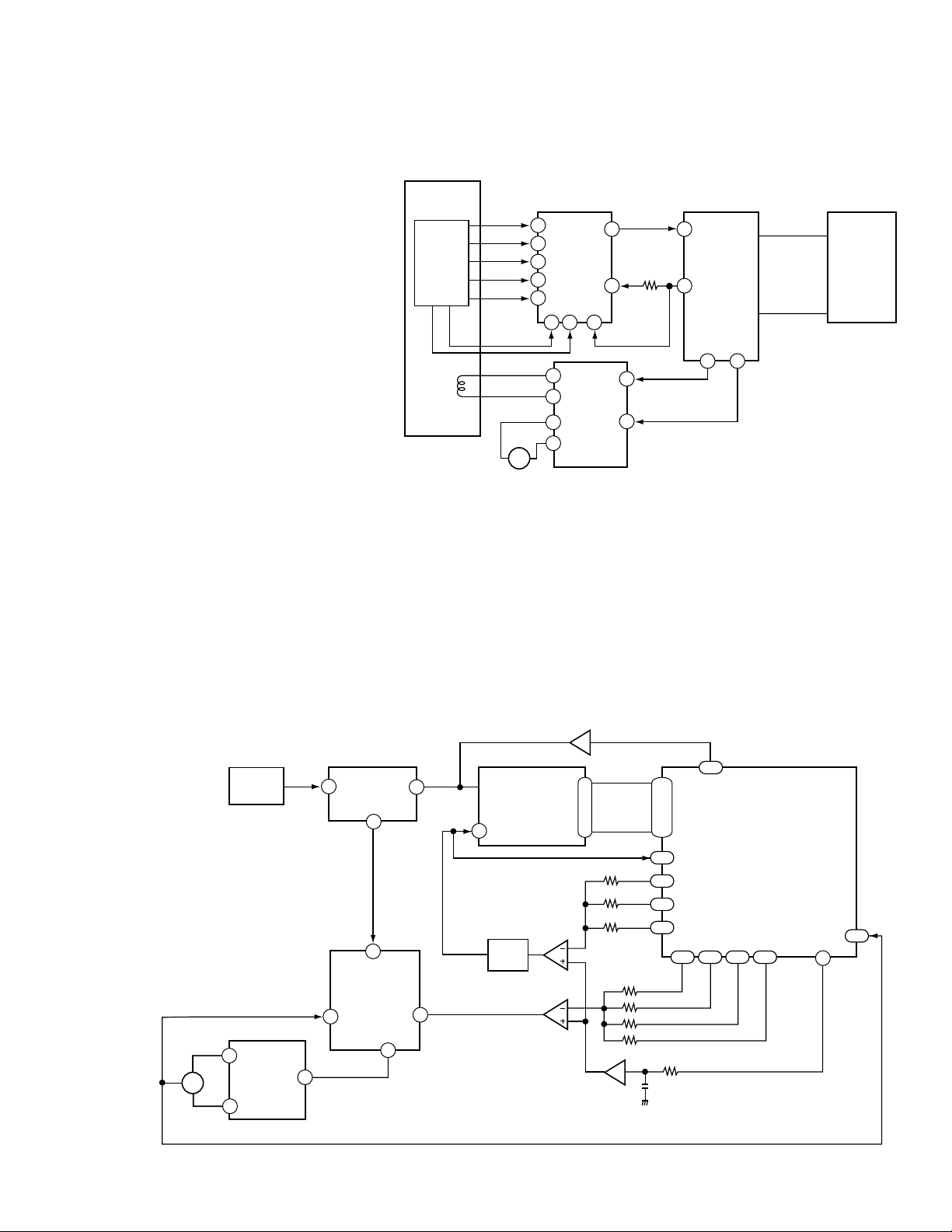
1.2.3 Tracking / Slider Servo
DV-515
ATB: For phase differential TE (use for DVD),
the tracking balance compensation is
achieved by outputting the offset from
the TBAL output at pin 44 of the digital
servo IC, and by biasing the charge pump
resistor for phase-difference error of
RFIC.
For 3-beam TE (use for CD), the tracking
balance compensation is achieved by
adjusting the gain balance of A and C in
RFIC with the voltage of RFIC-pin 30.
The difference is detected by processing
TE at pin 32 of IC 201 with an internal
digital equalizer.
TDO: In addition to the servo output, the low-
band components, such as the kick-brake
for jump, are added for TDO output.
SLDO: The low-band components of TE are
processed by the internal digital
equalizer, and deadband is added for
SLDO output. The offset voltage for
pickup movement is also included in the
SLDO output.
• TRACKING / SLIDER SERVO
PICKUP
OEIC
TRKG
COIL
TE RF
B1
B2
B3
B4
AC
M
SLDR
5
6
IC101
7
RFIC
LA9701M
8
9
13 14 30
11
12
15
16
IC151
DRIVER
TE
TBAL
TDO
SLDO
32
IC201
DIGITAL
44
SERVO IC
LC78651W
48
45
ADDRESS
&
BUS
IC501
MECH.
CONTROL
PE5012A
35
39
CP
6
26
1.2.4 SPINDLE SERVO
For a CD, the RF signal output from pin 46 of the RF IC is converted
to binary in IC201. By comparing the binary value with the reference
CLK (clock), the SPDL ERR signal is output from pin 46.
• SPDL SERVO
RFO
54
CLK
(27M)
29
46
SPDL +
SPDL
M
SPDL -
OEIC
12
IC251
DRV
BA6195FP
13
(Base)
RF
FG
25
IC101
3
RFIC
LA9701M
RF
DIGITAL
SERVO
55
LC78651W
SPDO
46
39
IC201
For a DVD, the SPDL ERR signal is generated from the PWM signal
output from LSI-ΙΙ. Upon receiving this signal via pin 29, IC201
also outputs it from pin 46, switching from the CD SPDL ERR
signal.
IC301
A/D
ADC1175CIJMX
12
IC302
VCO
IC261
(1/2)
(2/2)
3
|
10
V165
ATC
8 bit
IC261
(1/2)
APC
AFC
ASC
200
|
207
176
178
180
177
161 163 166 168
FPWM
VPWM
PPWM
RPWM
DUTY50
179
IC701
LSI II
PD4833A
159
95
FG
5
DV-515
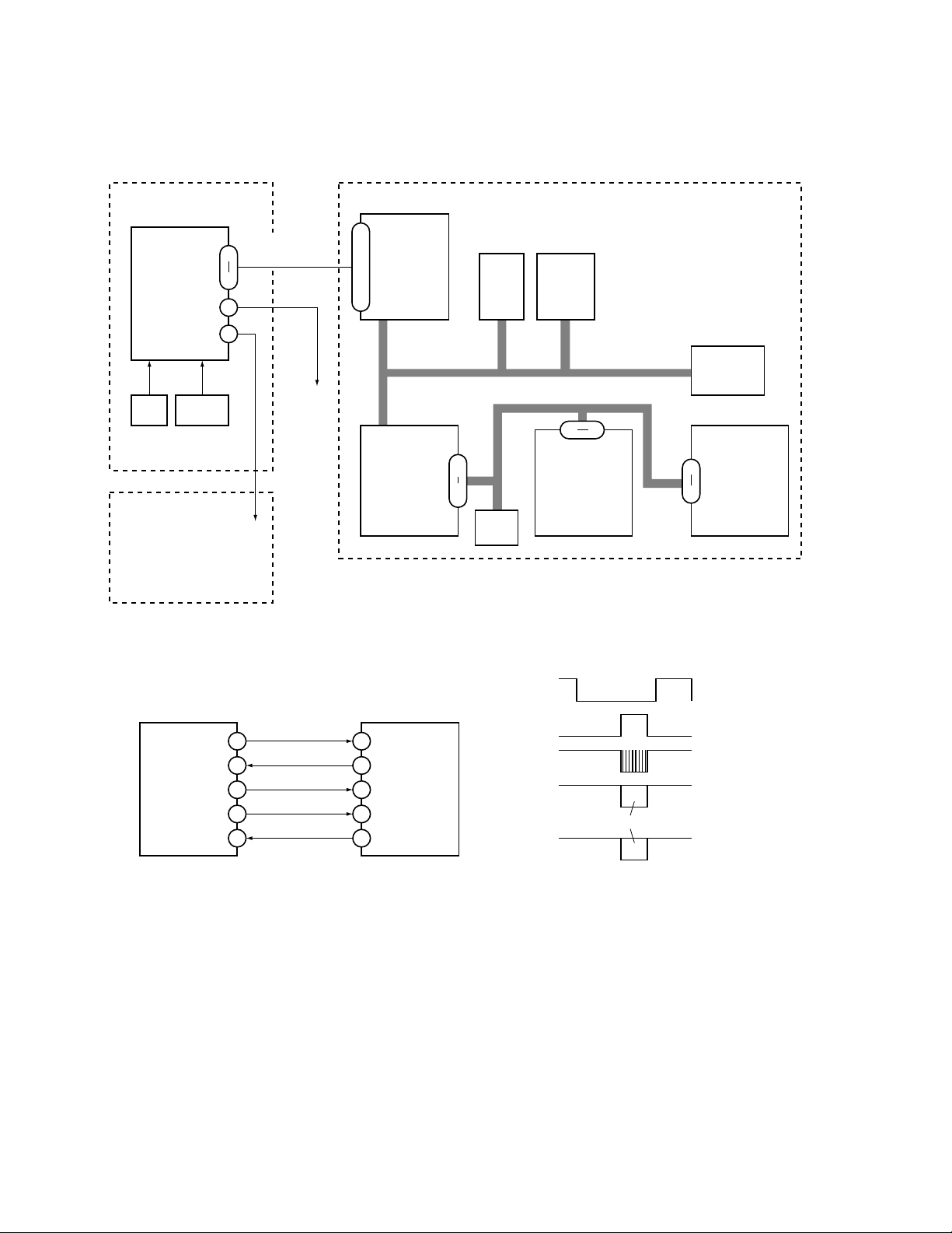
1.2.5 System Control (DV-515)
FLKY DVDM
IC601
PD3381A
System
Cont.
102,107,108,111
DATA,ADDRESS
MAIN BUS
IC701
PD4833A
LSI-11
IC101
PE5018B
Mode Control
(FL Cont.)
Remote
KEY
Sensor
13 16
22
21
SI1,SO1
SCK1,XRDY
POWER ON
XRESET
POWER SUPPLY
ASSY
1) Interface between Mode Cont. and System Cont.
142 151
IC604
Work
RAM
IC502
SRAM
IC603
FLASH
ROM
MAD0–MAD7
10 17
IC501
PE5012A
Mech. Cont.
(DVD)
XRDY
IC801
MB86371C
AV-Dec.
IC201
LC78651W
Digital
63 70
Servo
IC101
PE5018B
Mode Control
(FL Cont.)
13
46
14
15
16
XRDY
LT1
SCK1
SO1
SI1
102
65
111
107
108
IC601
PD3381A
System
Cont.
LT1
SCK
SI
DATA
SO
Timing Chart
If there is no communication for 2 sec.,
Mode Cont. turn off the power and reset.
6

2. TEST MODE
DV-515
2.1 HOW TO ENTER THE TEST MODE
There is the two following methods in an enters of the test mode.
1. Input [ESC] key and [TEST/RANDOM] key of the LD test mode
remote control unit in order under the power on condition.
2. Connect a personal computer with the RS232C terminal
(CN106), and input entry command (TE) of test mode from the
personal computer.
Note: FL indication and LED come all to light until key operation
2.2 RELEASE THE TEST MODE
There is the three following methods in a release of the test mode.
1. Turn the power off.
2. Press [ESC] key of the remote control unit. At this time, reset it
for a while except for during the LD and CDV set.
3. Connect a personal computer with the RS232C terminal
(CN106), and input normal mode entry command (NE) from
the personal computer.
is done when entering the test mode.
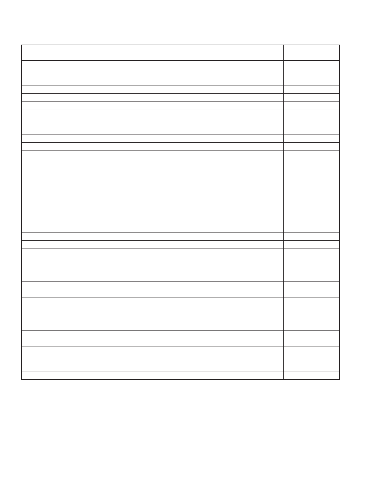
2.3 LIST OF TEST MODE FUNCTION
Contents of Command
Open STOP REPEAT A A8 – 48
Close OPEN REPEAT A A8 – 48
Stop PLAY REPEAT B A8 – 44
Play (DVD is only tracing.) STOP TV/LDP A8 – 0F
Increase the address (at FTS coefficient indication mode) –––––
Play (DVD is with decode.) STOP PLAY A8 – 17
Pause on PLAY CX A8 – 0E
Decrease the address (at FTS coefficient indication mode) –––––
Pause on/off PLAY/PAUSE PAUSE A8 – 18
Search address input (0 to 9) 0 to 9 A8 – 00 to 09
∗ Use for other numerical value input
Search address input (A to F) During address input PGM+1 to 6
1 Search address clear During address input CLEAR A8 – 45
2 Escape the search input mode Address = 0
Change the search address input mode +10 A8 – 1F
(Off=absolute address=addition=subtraction=Off)
∗ Use for other numerical value input
Search execution (ignore the wrong address) CHP/TIM A8 – 13
Tracking open PLAY STEP FWD A8 – 54
Tracking close PLAY STEP REV A8 – 50
Slider in TR : Off SCAN REV A8 – 11
Low speed scan REV TR : On SCAN REV A8 – 11
Scan REV (Jump number is variable) TR : On Shuttle REV A8 – 2C to 2F
Slider out TR : Off SCAN FWD A8 – 10
Low speed scan FWD TR : On SCAN FWD A8 – 10
Scan FWD (Jump number is variable) TR : On Shuttle FWD A8 – 28 to 2B
Loading in STOP SKIP REV A8 – 53
Loading out STOP SKIP FWD A8 – 52
LD on (650 nm) TEST+1 A8 – 5E + A8 – 01
Condition
Key Name of
Remote Control Unit
Shuttle REV A8 – 2C to 2F
Shuttle FWD A8 – 28 to 2B
Code of Remote
Control Unit
7
DV-515
Contents of Command
Focus on TEST+2 A8 – 5E + A8 – 02
Focus sweep TEST+3 A8 – 5E + A8 – 03
LD on (780 nm) TEST+4 A8 – 5E + A8 – 04
Focus jump + MULTI FWD A8 – 58
Focus jump – MULTI REV A8 – 55
Spindle FG on TEST+5 A8 – 5E + A8 – 05
AFB on/off TEST+6 A8 – 5E + A8 – 06
FTS coefficient indication After the address four-digit input TEST + 9 A8 – 5E + A8 – 09
CD error rate indication PLAY TEST + 0 A8 – 5E + A8 – 00
Jitter indication TEST + DIG/ANA A8 – 5E + A8 – 0C
Scrren indication on/Switching of the first and second screen OSD : Off/On DISPLAY A8 – 43
Screen indication off OSD : On AUDIO A8 – 1E
Screen indication on/off PROGRAM A8 – 4C
Switching of ID display methods (decimal/hexadecimal) DIG/ANA A8 – 0C
DISC type designation STOP HILITE/INTRO A8 – 5A
• Forced designation to DVD +1 +A8 – 01
• Forced designation to CD +3 +A8 – 03
• Request for Disc sensing +0 +A8 – 00
Tray close of disc sense inhibition Checker mode REPEAT A A8 – 48
Background color (eight colors) switching 2/R A8 – 49
Background color (eight colors) switching (reverse toggle) 1/L A8 – 4B
Video : Component output DIGITAL EFFECT A8 – 5C
Video : Composite output STILL WITH SOUND A8 – 5B
Audio : 5.1CH forced output TEST + FRONT A8 – 5E +
(5.1CH output model only) A3 – 99 AF – 65
Audio : Speaker setting change mode on TEST + CENTER A8 – 5E +
(5.1CH output model only) A3 – 99 AF – 66
Audio : Speaker setting change TEST + REAR A8 – 5E +
(5.1CH output model only) A3 – 99 AF – 67
Audio : 5.1CH forced output off and setting change TEST + LFE A8 – 5E +
mode off (5.1CH output model only) A3 – 99 AF – 68
Audio : Speaker setting change mode on Checker mode ESC + CENTER A8 – 5F +
(5.1CH output model only) A3 – 99 AF – 66
Audio : Speaker setting change Checker mode ESC + REAR A8 – 5F +
(5.1CH output model only) A3 – 99 AF – 67
Audio : Speaker setting change mode off Checker mode ESC + LFE A8 – 5F +
(5.1CH output model only) A3 – 99 AF – 68
RF AGC OFF D-LEVEL+0 A8 – 37 + A8 – 00
RF AGC ON D-LEVEL+1 A8 – 37 + A8 – 01
Condition
Key Name of
Remote Control Unit
Code of Remote
Control Unit
8
 Loading...