

Sony DTC-57ES User Manual

Digital Audio
Tape Deck
3-753-350-21(1)
Operating Instructions
Digital AudioTape
DTC-57ES
O 1991 by Sony Corporation

WARNING
Operating Instructions
Before operating the unit, please read this manual
thoroughly and retain it for future reference.
Owner's Record
The model number is located on the rear exterior and serial
number is on the rear. Record the serial number in the
space provided below. Refer to these numbers whenever
you call upon your Sony dealer regarding this product.
Model No. DTC-57ES
Serial No._
WARNING
To prevent fire or shock hazard, do not
expose the unit to rain or moisture.
INFORMATION (For the customers In the U.S.A.)
This equipment generates and uses radio frequency
energy and if not installed and used properly, that is, in
strict accordance with the manufacturer's instructions, may
cause interference to radio and televisions reception. It has
been type tested and found to comply with the limits for a
Class 6 computing device in accordance with the
specifications in Subpart J of Part 15 of FCC Rules, which
are designed to provide reasonable protection against
such interference in a residential installation. However,
there is no guarantee that interference will not occur in a
particular installation. If this equipment does cause
interference to radio or television reception, which can be
determined by turning the equipment off and on. the user is
encouraged to try to correct the interference by one or
more of the following measures:
Reorient the receiving antenna
Relocate the equipment with respect to the receiver
Move the equipment away from the receiver
Plug the equipment into a different outlet so that
equipment and receiver are on different outlet so that
equipment and receiver are on different branch circuits.
If necessary, the user should consult the dealer or an
experienced radloAelevision technician for additional
suggestions. The use may find the following booklet
prepared by the Federal Communications Commission
helpful:
'How to identify and Resolve Radio-TV Interference
Problems'. This booklet is available from the U.S.
Government Printing Office, Washington. DC 20402. Stock
No. 004-000-00345-4.
This symbol is intended to alert the
user to the presence of uninsulated
"dangerous voltage* within the prod
uct's enclosure that may be of suffi
cient magnitude to constitute a risk of
electric shock to persons.
This symbol is intended to alert the
user to the presence of important
operating and maintenance (servicing)
instructions in the literature accompa
nying the appliance.
* The graphical symbol are on the rear enclosure.
For the customers in Canada
This apparatus complies with the Class B limits for radio
noise emissions set out in Radio Interference Regulations.
For the customers in Canada
-CAUTION: --------------------------------------------------------------------
TO PREVENT ELECTRIC SHOCK. DO NOT USE THIS
POLARIZED AC PLUG WITH AN EXTENSION CORD.
RECEPTACLE OR OTHER OUTLET UNLESS THE
BLADES CAN BE FULLY INSERTED TO PREVENT
BLADE EXPOSURE.

Table of Contents
Before using the DAT deck
Warning............................................................................................2
Digital audio tape...............................................................................3
Precautions...................................................................................... 4
Features........................................................................................... 5
Location and function of controls....................................................... 6
Front panel/remote commander
Remote commander operation....................................................9
Installing batteries
Display window.........................................................................10
Connections....................................................................................12
Rear panel jacks........................................................................12
Connecting cords......................................................................13
Connecting the remote control system.......................................13
Connection examples
Clock setting
Cassette loading..............................................................................18
...................................................................................
Setting the date and time
......................................................................
...............................................................
..................................................
...........................................................
Recording
Before recording..............................................................................19
Blank section and sound muted portion.....................................19
Absolute time codes..................................................................19
Recording....................................................................................... 20
To store the recording date and time..........................................21
To check the recording date and time
Creating a sound muted portion
End search
Fade-in/fade-out recording.........................................................24
CD synchronized recording....................................................... 24
...............................................................................
........................................
................................................
21
Writing sub codes
Subcodes........................................................................................25
Start ID............................................................................................ 27
Writing automatically during recording.......................................27
Writing manually during recording
Writing manually during playback
Adjusting the position................................................................28
Erasing..................................................................................... 28
Program numbers
...........................................................................
.............................................
..............................................
Writing automatically during recording
Renumbering
Erasing.....................................................................................30
Skip ID............................................................................................31
Writing during recording........................................................... 31
Writing during playback............................................................31
6
9
Erasing.................................................................................... 31
End ID.............................................................................................32
Writing during recording............................................................32
Writing during playback.............................................................32
Erasing.....................................................................................33
...........................................................................
......................................
29
30
Playback
Playback......................................................................................... 33
14
16
16
23
23
28
28
29
Display window
Various playback operations............................................................35
Fade-inAade-out play
Repeat play...............................................................................35
Automatic music sensor operation
Music scan............................................................................... 36
Designating the desired selection
Skip play...................................................................................37
Auto play: restarting playback after rewinding
Random music sensor operation...............................................38
Timer activated operation................................................................. 39
Timer activated recording
Timer activated playback
Maintenance....................................................................................40
Cleaning the cabinet..................................................................40
Cleaning the head
Block diagram
Guide to the serial copy management system...................................42
Technical information
Recording format of DAT...........................................................44
Tape format and construction of DAT cassette
Track format..............................................................................45
T roubleshooting
Specifications..................................................................................49
........................................................................
................................................................
............................................
..............................................
............................
..........................................................
...........................................................
.....................................................................
................................................................................
......................................................................
...........................
.............................................................................
34
35
36
37
37
39
39
40
41
44
44
46
Digital Audio Tape
DAT (Digital Audio Tape) is a new recording system which
digitalizes the audio signal and records it on a DAT
cassette tape.
DAT records the audio signal by converting the analog
sound into a digital signal. This converting system is called
the PCM (Pulse Code Modulation), and its accurate
processing of the audio signal allows recording/playback
with lower wow and flutter, wider dynamic range, lower
distortion rate, and superb signal-to-noise ratio.
In addition, various control codes calls sub codes can be
written on the DAT cassette separately from the audio
signal. They are written for a variety of convenient
playback/tape editing operations, and except for the
absolute time, can be rewritten after audio signal recording
has been completed.

Precautions
Safety
• Operate the unit only on 120 V AC, 60 Hz.
• One blade of the plug is wider than the other for the
purpose of safety and will fit into the power outlet only one
way. If you are unable to insert the plug fully into the outlet,
contact your dealer.
• Should any solid object or liquid fall into the cabinet,
unplug the unit and have it checked by qualified personnel
before operating it any further.
• Unplug the unit from the wall outlet if it is not to be used
for an extended period of time. To disconnect the cord,
pull it out by grasping the plug. Never pull the cord itself.
Operation
Before making program source connections, be sure to
unplug the unit.
Installation
• Do not install the unit in a location near heat sources such
as radiators or air ducts, or in a place subject to direct
sunlight, excessive dust, mechanical vibration or shock.
• Do not place anything on the top of the cabinet. The top
ventilation holes must be unobstructed for the proper
operation of the unit and to prolong the life of its components.
NOTE
When closing the cassette compartment, do not push
the cassette lid forcibly by hand, but perform with
the OPEN/CLOSE button.
For the customers in the U.S.A.
For detailed safety precautions, see the ’IMPORTANT
SAFEGUARDS’ leaflet.
If you have any question or problem concerning your unit,
please consult your nearest Sony dealer.
Moisture Condensation
If the unit is brought directly from a cold to a warm location,
moisture may condense inside the unit. In this condition,
the tape may adhere to the head drum and be damaged, or
the unit may not operate correctly. Always remove the
cassette when the unit will not be used.
If moisture is present...
e Function controls will not operate,
e All operations will stop.
When the CAUTION indicator lights and the unit will not operate
Leave the unit turned on for about an hour.
Detaching the Side Panels
After removing the screws, secure the cabinet with the
supplied lock screws (M4 x 6). Do not use the longer
screws.
For safety, before doing this, be sure to disconnect the AC
power cord from the AC outlet.

Serial copy management system
Excellent sound quality
This unit utiiizes the seriai copy management system that
permits digital-to-digital recording for one generation. You
can record CD sound or other digital formats through a
digital-to-digital connection. (See page 42.)
Date Function automatically memories the recording date and time
The year, month, day, day of the week. hour, minute and
second are automatically memorized in the subcode area
during recording, so that during playback you can display
this data to check when the tape was recorded. This
function is especially convenient when recording live
performances, etc.
Three sampling frequencies
Recording/piayback can be done with three sampling
frequencies (48 kHz. 44.1 kHz and 32 kHz).
48 kHz: For analog and digital input signals in a standard
mode.
44.1 kHz; For compact disc and pre-recorded DAT tape.
32 kHz: For analog input signals in a long-play mode.
Long play mode
This unit can operate in a long-play mode. Analog input
signals can be recorded or playback for up to four
consecutive hours when the DT-120 DAT cassette tape is
used. The sampling frequency will be 32 kHz in the long-
play mode.
Visible cassette loading
1-bit A/D converter
For the A/D converter section which converts analog input
signals to digital signals, the unit employs a 1-bit A/D
converter which theoretically generates no zero-cross
distortion for a clear, elegant sound quality.
Pulse D/A converter
Superior playback performance is achieved with a 1-bit D/A
converter.
Rich variety of subcode information
This unit can record subcode information such as Start IDs.
program numbers. Skip IDs, and absolute time data,
enabling you to quickly locate tunes and display the
playback time in the same manner as when playing
compact discs.
Digital tade-in/fade-out
Professional sounding fade-in/fade-out of either digital or
analog signals can be accomplished by use of the FADER
button.
Post edit recording of sub codes
You can record or rewrite the following sub codes after the
audio signal recording has been completed.
Start ID: Signifies the beginning of a seiection.
Program number; Gives a number to the selection.
Skip ID; Signifies the beginning of a portion to be skipped.
End ID; Signifies the end position of recording/piayback.
Since sub codes are written on the tape separately from
audio signals, the audio signals are not affected.
You can view the tape operation through the lid of the
cassette compartment. Due to a revolutionary new
transport mechanism, cassette loading time has been
significantly reduced.
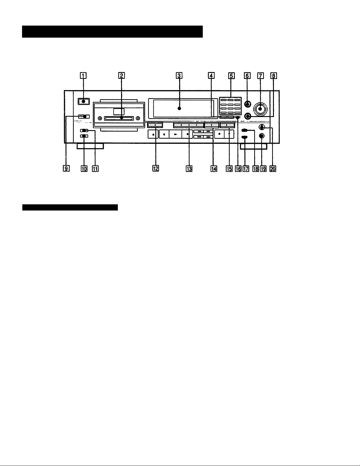
Location and Function of Controls
Front Panel/Remote Commander
HI POWER switch
Turns the power on and off.
H] Cassette compartment
Insert a cassette with the window side up and the safety
tab facing you.
[3] Display window
[4] DATE buttons
RECORDED: Press to display the recording day of the
tape being played.
PRESENT: Press to display the current lime.
Each time the RECORDED or PRESENT button is
pressed, day, month and year display, the day of the
week display or hour, minute and second display is
switched sequencially.
H] Music select buttons
Numeric buttons (0-S): Designate the desired program
number to be played back before starting playback.
Designate the desired number in the record-pause
mode, the program number is written consecutively
from the designated number.
CLEAR: Use to cancel the program number which has
been mistakenly entered.
MUSIC SCAN: Use this feature to listen to the beginning
of each selection successively.
(U INPUT selector
Set according to the signal to be recorded.
ANALOG: For recording from the equipment connected
to the LINE IN jacks.
OPTICAL: For recording from the equipment connected
to the DIGITAL IN (OPTICAL) jack.
COAXIAL: For recording from the equipment connected
to the DIGITAL IN (COAXIAL) jack.
[D REC LEVEL (recording level) control
Adjust the recording level for the analog input signals.
When recording digital signals, it is not necessary to
adjust the recording level.
d] BALANCE control
Adjust the recording balance for the analog input signals.
When recording digital signals, it is not necessary to
adjust the recording balance.
m Remote sensor
Receives the signal from the Remote Commander.
on REC MODE selector
Normally set to the STANDARD position.
When this selector is set to the LONG position, you can
record analog input signals or digital signals with 32 kHz
in the long-play mode.
US TIMER switch
Normally set to the OFF position. When recording or
playing back at the desired time using a commercially
available audio timer, set to the REC position or the PLAY
position respectively.
m COUNTER buttons
MODE: Selects the counter display in the display window
among the linear counter (tape running time), absolute
time, elapsed time of the selection, and total remaining
time of tape. Each time you press the button, the
display changes sequentially.
RESET: Resets the linear counter to “OM OOS”.
H START ID buttons
AUTO: Press to turn on and off the AUTO indicator. When
the AUTO indicator is lit, the start ID will automatically
be written during recording. When the AUTO indicator
is not lit, press the START ID WRITE button at the point
where you want to write a start ID.
WRITE: Press to write the start ID at the desired point
during recording or playback.
ERASE: Press to erase a start ID. When a start ID and a
program number are written on the tape, both codes are
simultaneously erased by pressing this button.
RENUMBER: Press to renumber all programs on the tape.
When only the start IDs are written, pressing this button
will insert the proper program numbers beginning with
“1". The tape will rewind and start from the beginning to
accomplish this function.
m SKIP ID buttons
WRITE: Press at the beginning of the portion you may wish
to skip later. A skip ID will be written from the point
where you pressed this button.
ERASE: Press to erase the nearest skip ID which is before
the current position.
m END ID buttons
WRITE: Press to write the ID signifying the end of playback
or recording.
ERASE: Press to erase the end ID.
m CLOCK SET button
Press to adjust the time of the clock built in this unit.
In this mode, the MUSIC SCAN button and the 0 button
function as the + and - buttons respectively.
G2I MARGIN RESET button
Press to reset the margin of peak level.
m FADER button
Press to fade in or fade out during recording or playback.
QH Headphones Jack
Insert the headphones plug to this jack.
m PHONE LEVEL control
The PHONE LEVEL control adjusts the headphones volume
level.

Location and Function of Controls
Front Panel/Remote Commander
HD OPEN/CLOSE button
Press to open or close the cassette compartment.
Tape operating buttons
■ (stop): Press to stop recording or playback.
► (play); Press to play back the tape.
•REC (recording): Press toenter the record-pause mode.
After pressing this button, press the ll or ► button.
llPAUSE (pause): Press to stop for a moment during
recording or playback. To restart recording or playback,
press this button again or press the >■ button.
If the unit is left in the pause mode for about 10
minutes, it wiil automatically be released and the
deck will enter the stop mode. To restart recording
or playback from the stop mode, press the «REC or ►
button respectively.
OREC MUTE (record muting): Inserts a sound-muted
portion (space).
(AMS): Press to locate the beginning of the
selection during the playback.
(rewind/review, fast-forward/cue): In the stop
mode, press to rewind/fast-forward the tape. During
playback, press to rewind or fast-fonward the tape while
listening to the sound.
m DISPLAY MODE button
Changes the display mode. (Refer to page 10.)
Wi RMS play buttons
ENTER: To program the selections in a desired order,
press this button after pressing the numeric buttons.
CHECK: Press to check the programmed contents.
REPEAT 1/ALL button
Press to play a desired portion repeatedly. Each time you
press the button, the indicatior changes as follows;
REPEAT 1 -► REPEAT ALL -► off
SKIP PLAY button
Press to activate the skip ID code function. The portion of
the tape previously marked will be skipped.
I
CD operation buttons
Operative only for the Sony CD player equipped with a
Remote Commander.
II (pause): Press this button twice to start playback Press
this button once in the playback mode, the deck enters
the pause mode.
(AMS): Press to locate the desired selection on
the Compact Disc during playback or in the stop mode.
I
CD SYNCHRO (CD synchronized recording) buttons
(The playback of the Sony CD player equipped with a
Remote Commander and the recording of the DAT deck
can be performed simultaneously.)
STANDBY: Press to set the unit in the record-standby
mode.
START: Press to start recording of the DAT deck and
then playback of the CD player.
STOP: Press to stop the DAT deck recording and the CD
player playback.
8
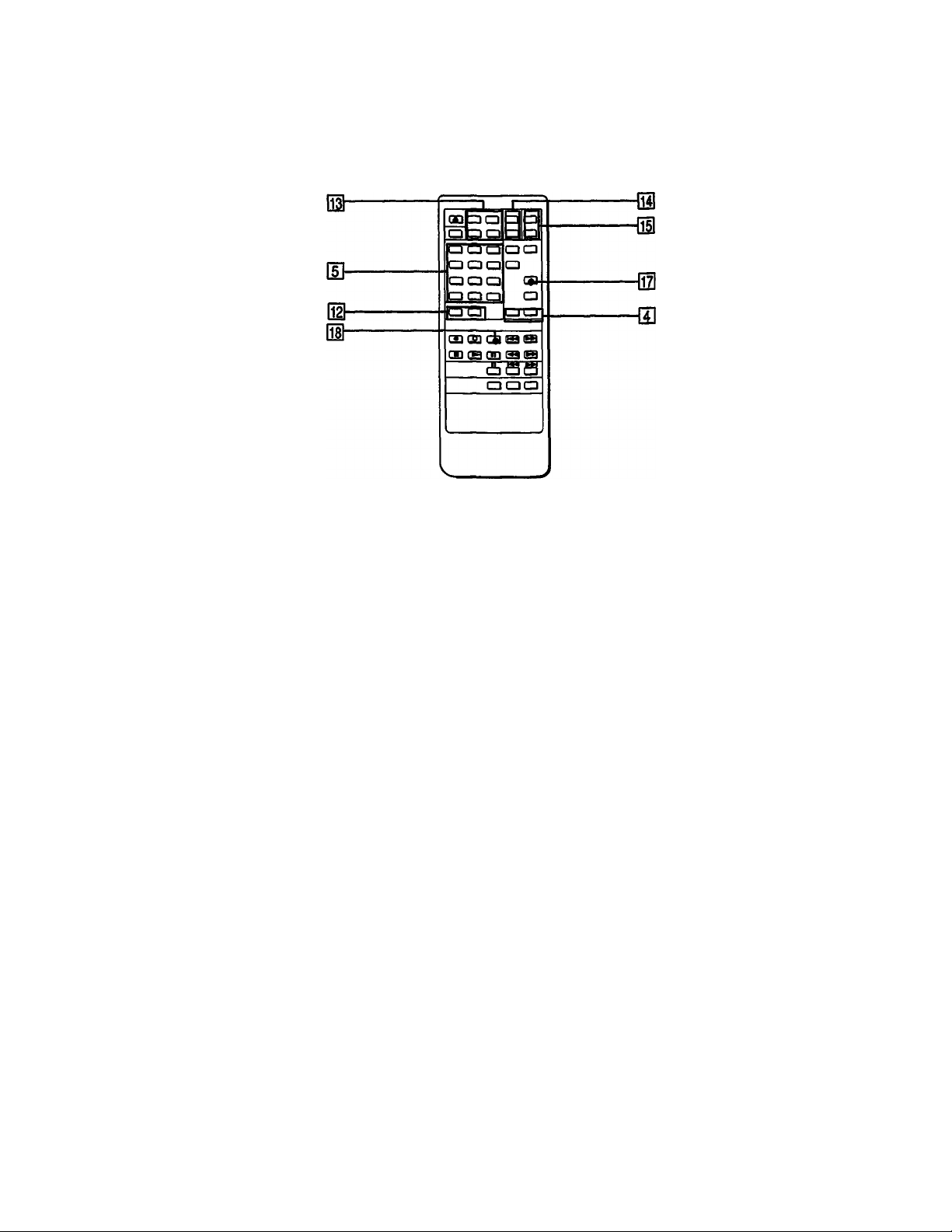
Remote Commander Operation
Each button on the remote commander functions in the
same way as those having the same name on the front
panel.
However, the following operations cannot be performed
using the remote commander. Use the front panel controls
instead.
• Turing the power on and off
• Selecting digital(optical/coaxial)/analog input source
• Setting the clock
• Adjusting the recording level and balance
• Adjusting the headphones level
• Setting the timer recording/piayback
• Selecting the record mode (standard or long)
The following operations can be performed only with the
remote commander.
• Activating CD synchronized recording using a Sony CD
player and controlling the CD player
• Locating the desired selection on the Compact Disc or
setting the CD player in the pause mode (possible only
when a Sony CD player is used.)
• Repeat play
• Skip play
• RMS* play
*RMS: Random Music Sensor
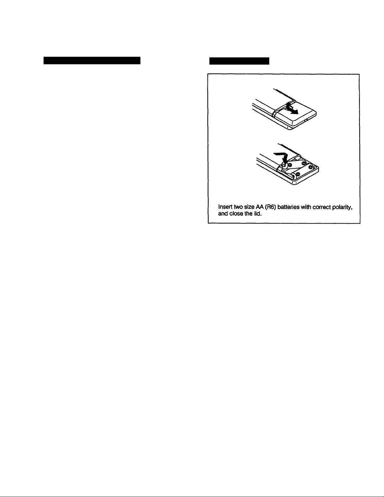
Installing Batteries
Notes on remote control
e Do not expose the remote sensor on the deck to strong
light such as direct sunlight, lighting apparatus, etc.
e Do not place any obstructions between the Remote
Commander and the remote sensor, or else operations will
not be performed correctly.
• The controllable range is limited. Point the Remote
Commander directly at the remote sensor on the deck.
• When remote control operation distance becomes shorter,
the batteries are weak. Replace both batteries with new
ones.
To avoid battery leakage
When the commander will not be used for a long period of
time, remove the batteries to avoid damage caused by
battery leakage and corrosion.
Battery life
About half a year of normal operation can be expected
when using the Sony SUM-3 (NS) batteries.

Location and Function of Controls
Display Window
To turn off the display window
When the power is turned on, the display window also is
turned on. During recording or playback, all display or
some parts of the display can be turned off as follows;
When operating with the front panel controls
While pressing the COUNTER MODE button, press the 0
button.
When operating with the remote commander
Press the DISPLAY MODE button.
Each time you press the above buttons, the indicators
change as follws:
Normal indicators
i
Peak level meters and margin indicators go off.
(The DISPLAY OFF indicator lights.)
1
All the indicators go off during recording or playback*.
I (The DISPLAY OFF AUTO indicator lights momentarily
just before the indicators go off.)
* When pressing the COUNTER MODE or DISPLAY MODE button
except during recording or playback, the DISPLAY OFF AUTO
indicator lights. In this case, all the indicators go off immediately
after recording or playback starts.
To change the brightness of the display window
While pressing the COUNTER MODE button, press one of
the numeric buttons 1, 2 and 3. The greater number
pressed, the darker the display window becomes.
(When operating with the remote commander, also press
the COUNTER MODE button.)
G] LONG PLAY mode indicator
Lights when recording or playback is being performed in
the long play mode.
m TOC (Table Of Contents) indicator
When a pre-recorded DAT cassette is played back, this
indicator will light.
m DATE indicator
Lights when pressing the RECORDED button to display
the recording day of the tape being played. Flashes
when pressing the PRESENT button to display the current
time.
[D REMAINING (remaining time): Lights when the counter
shows the remaining time of the tape.
PGMTIME (program time): Lights when the counter shows
the elapsed time of the current selection.
ABS TIME (absolute time) indicator: Lights when the
counter shows the elapsed time from the beginning of
the tape.
[D Time indicator
Indicates the tape running time, absolute time, elapsed
time of the current selection, remaining time or recording
day. Each time the COUNTER MODE button is pressed,
the display is changed.
ID Fade in/out indicator
: Rashes when recording or playback fades in.
(»¿*“1: Rashes when recording of playback fades out.
10
ID AM/PM indicators
Show AM or PM of the time.

[D INPUT selector indicators
The OPTICAL or COAXIAL indicator lights according to
the position of the INPUT selector. No indicator lights when
the INPUT selector is set to the ANALOG position.
m SAMPLING FREQ. (Sampling frequency) indicator
48 kHz: For recording/piayback of analog input signals
(standard mode)
44.1 kHz: For recording/piayback of CD or a pre-recorded
DAT cassette
32 kHz: For recording/piayback of analog input signals
(long-play mode)
Qi REPEAT indicators
REPEAT 1: Lights when a desired selection is played
back repeatedly.
REPEAT ALL: Lights when all the selections are played
back repeatedly.
m] AMS (Automatic Music Sensor)/RMS (Random
Music Sensor) indicators
Show the number of selections to be skipped ahead or
behind in the AMS operation. When designating aselection
directly by the numeric button and the ► button, the
display shows the program number of the target selection
while the selection is being searched for. When
programming the desired selections in the RMS operation
(page 38), the display shows the program number of the
selection to be programmed.
m DISPLAY OFF/AUTO indicators
The DISPLAY OFF indicator lights when peak level meters
and margin indicators are turned off. The DISPLAY OFF
AUTO indicator lights momentarily before all the indicators
are turned off.
m SKIP PLAY indicator
When this indicator is lit during playback, the portion
marked by the skip ID is skipped and playback continues
from the next start ID.
|h| music scan indicator
Lights after pressing the MUSIC SCAN button to listen to
the beginning of each selection successively.
SHIFT RENUMBER: Lights when shifting the start ID and
program number position.
QZl SKIP ID mode indicator
WRITE: Lights when writing the skip ID.
ERASE: Lights when erasing the skip ID.
01)
END ID mode indicator
WRITE: Lights w/hen vwiting the end ID.
ERASE: Lights when erasing the end ID.
QD START ID indicator
Flashes when writing (for 9 or 18 seconds) or erasing a
start ID code, and lights when the start ID is detected durin
playback.
SKIP ID indicator
Lights when writing (for 1 or 2 seconds) or erasing a skip
ID code or when the skip ID is detected during playback.
mi MARGIN indicator
Shows how much margin there is between the peak level
of input audio signal and 0 dB.
m REHEARSAL indicator
Lights while the rehearsal function is activated (page 28).
m COPY PROHIBIT indicator
Lights when recording the digital signal with the copy
prohibit code. In this case, record with the LINE IN jacks.
M STEP/PGM NO. indicator
Shows the program number of the selection being played.
When programming the desired selection in the RMS
operation (page 38), the display shows the step number
of the programmed selection.
mi Frequencies map
When pressing the 4 button while keeping the COUNTER
MODE button pressed, bars indicating the sampling
frequencies with which the tape was recorded appear on
the peak level meters.
QD CAUTION indicator
Lights when moisture condensation occurs. If this happens,
the deck stops functioning automatically. (See page 4.)
im START 10 mode indicators
AUTO: Lights when the AUTO button is pressed to write
the start ID automatically.
RENUMBER; Lights when the RENUMBER button is
pressed to renumber the program numbers.
WRITE: Lights when writing the start ID manually.
ERASE: Lights when erasing the start ID.
AUTO RENUMBER: Lights when renumbering program
numbers automatically.
imi Peak level meters
Indicate the level of the audio signal being recorded
during recording, and the peak values of the audio signal
recorded on the tape during playback.
mi Tape operation indicators
IrEc I: Lights during recording or in the record-pause
mode.
►: Lights during recording or playback. It also lights in the
record-pause mode or in the play-pause mode.
II; Lights in the record-pause mode or in the play-pause
mode.
11
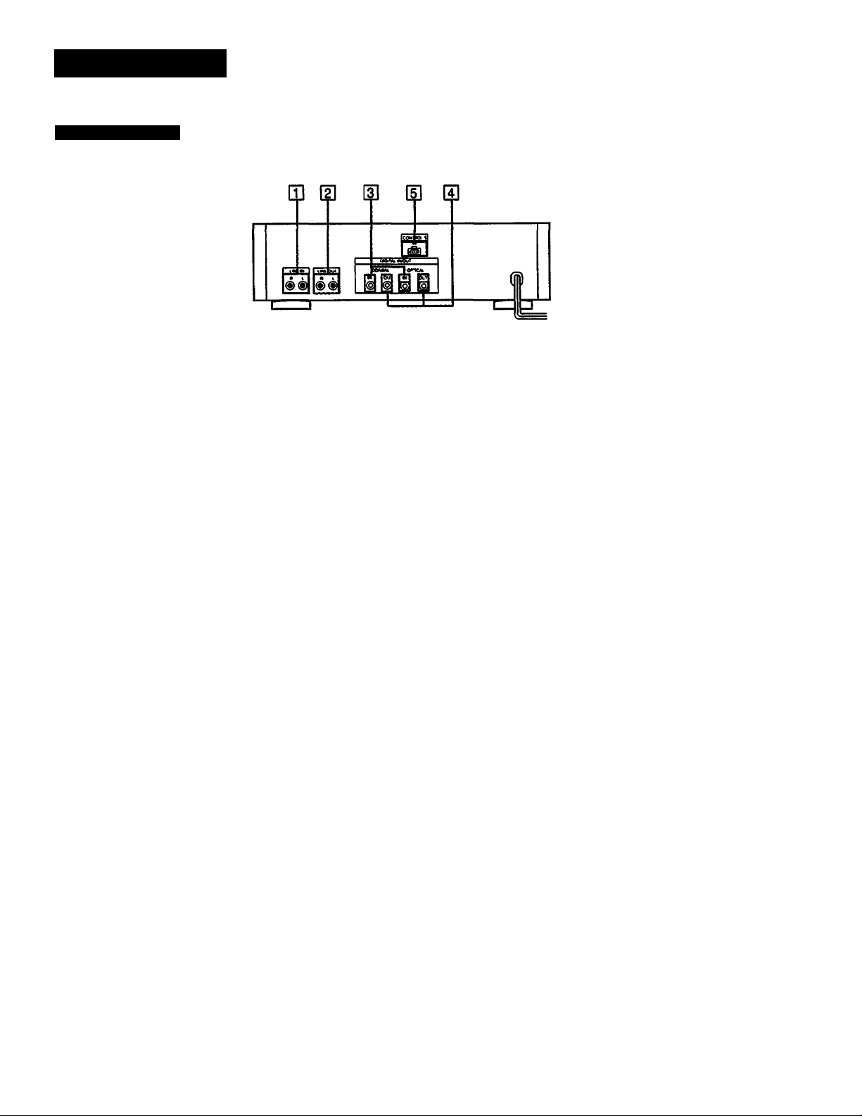
Connections
Rear Panel Jacks
H] LINE IN (line input) jacks (phono Jack)
Connect to the recording outputs of an amplifier. Signals
supplied by the amplifier can be recorded using the
sampling frequency of 48 kHz in the standard play mode
or 32 kHz in the long play mode.
H] LINE OUT (line output) Jacks (phono Jack)
Connect to the OAT or tape inputs of an amplifier. The
playback signal of this deck will be output.
ID COAXIAUOPTICAL DIGITAL IN (digital input) Jacks
(coaxial phono Jack/optical Jack)
Connect to the digital outputs of an amplifier having a builtin D/A converter or other digital source, such as a CD
player for digital-to-digital recording.
S] COAXIAL/OPTICAL DIGITAL OUT (digital output) Jack
(coaxial phono Jack/optical Jack)
Connect to the digital inputs of an amplifier having a builtin D/A converter or another DAT deck, for playback of a
DAT cassette or digital-to-digital recording.
ID CONTROL'S IN Jack
Connect to the CONTROL-S output of a Sony amplifier or
receiver for remote control.
Notes on connection
e Use the connecting cords specified in the illustrations.
# Turn off the power for all equipments before making
connections.
e Be sure to insert the plugs firmly into the jacks Loose
connections may cause hum and noise. When unplugging,
grasp the plug and not the cord.
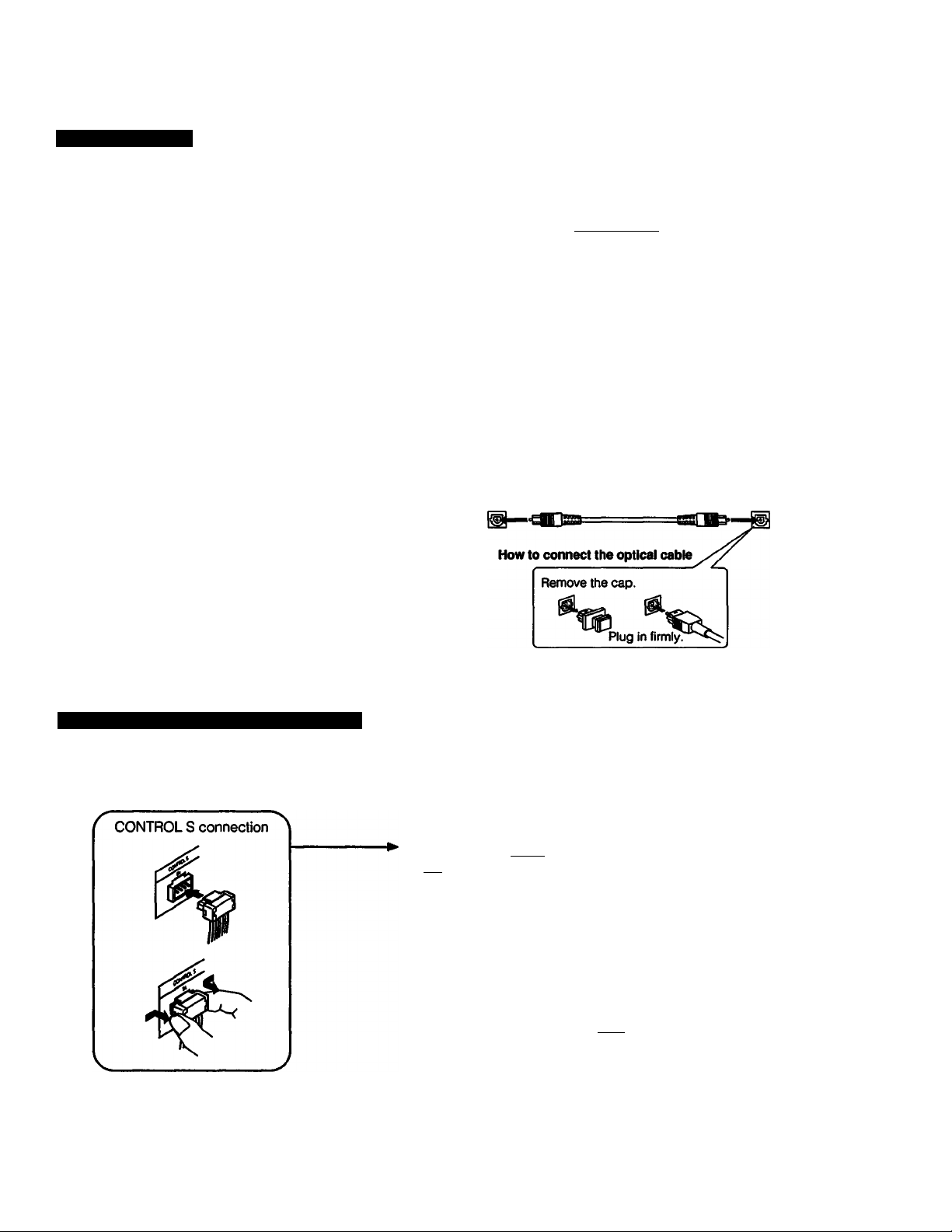
Notes on the optical cable
e Do not bend the cord. When the cord is not used, curl it
with a diameter of more than 15 cm (5 7, inches),
e Do not use it under high temperatures,
e When the optical cable is not connected, cover the
OPTICAL IN/OUT jacks with the supplied caps.
Note on sound signals
When connecting an optical cable to the DIGITAL IN/
DIGITAL OUT jacks, sound signals (L/R) are transmitted
together through the cable.
Note on the CONTROL-S IN Jack
To remotely control this unit through a receiver or amplifier,
connect the input of this unit to the CONTROL-S output of a
Sony receiver or amplifier, with a CONTROL-S cable. When
this connection is used, only remote control commands
sent through the receiver or amplifier will be executed. The
remote sensor of this unit will not function.
12
Connecting Cord
There are following three types of connecting jacks at the rear of the deck. Each type of jack requires a different type of
connecting cord.
Jack
LINE IN/OUT (analog input/output) jacks
COAXIAL IN/OUT (digital input/output) jacks
OPTICAL IN/OUT (optical transmission digital input/output) jacks
Required cord
Audio signal connecting cord
(supplied, or optional RK-C77 etc.)
Red White
LINE OUT White
Coaxial digital connecting cord
COAXIAL ^ ^ ' COAXIAL
OUT
OPTICAL OUT (optional POC-15, etc.) OPTICAL IN
(optional VMC-1ES, etc.)
Optical cable
Red LINE IN
IN
Connecting the Remote Control System
•é •è
r-' 1
I ■ I
O O Bl
CONTROL'S
IN
Amplifier or receiver
CONTROL'S
OUT
---------
1—, r
^to an AC outlet
to a wall outlet
13
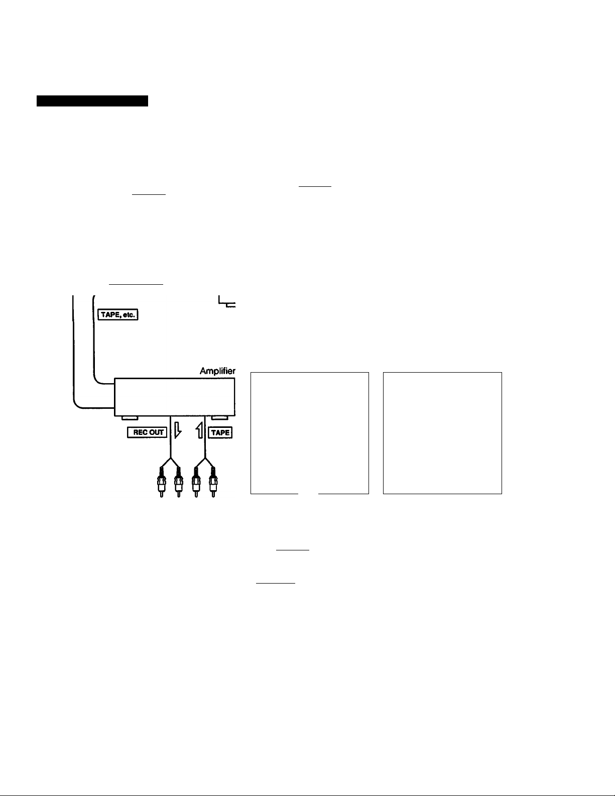
Connection Examples
If your amplifier is not equipped with digital signal jacks
I LINE OUT I
CD
yi—, I UNEOUT I
CD player
DAT deck
DIGITALIN
When recording via digitalto-digital connection,
connect a DAT deck (the
digital input) to DIGITAL
OUT (COAXIAL or
OPTICAL) of the DTC57ES.
: Analog signal
: Digital signal
(coaxial cable or optical cable)
: Signal flow
OICrrALOUT
DIGITAL OUT
7
-----------------------------------------
When recording via digitalto-digital connection,
connect the sound source
equipment (the digital
output) to DIGITAL IN
(COAXIAL or OPTICAL) of
the DTC-57ES.
I uwtx I UNEOUr
When connecting a microphone
Connecting a stereo microphone amplifier (the analog
output) to LINE IN of the DTC-57ES.
14
^^
CONTWCi.«
WAtWf
< own. QWCfH
k
¥
________________________
1^
DTC-57ES
J
i
to a wall outlet
Note
If 'COPY PROHIBIT" appears in the display window,
recording via digital-to-digital connection cannot be
performed.
In this case, connect the sound source equipment using
LINE IN and OUT jacks.
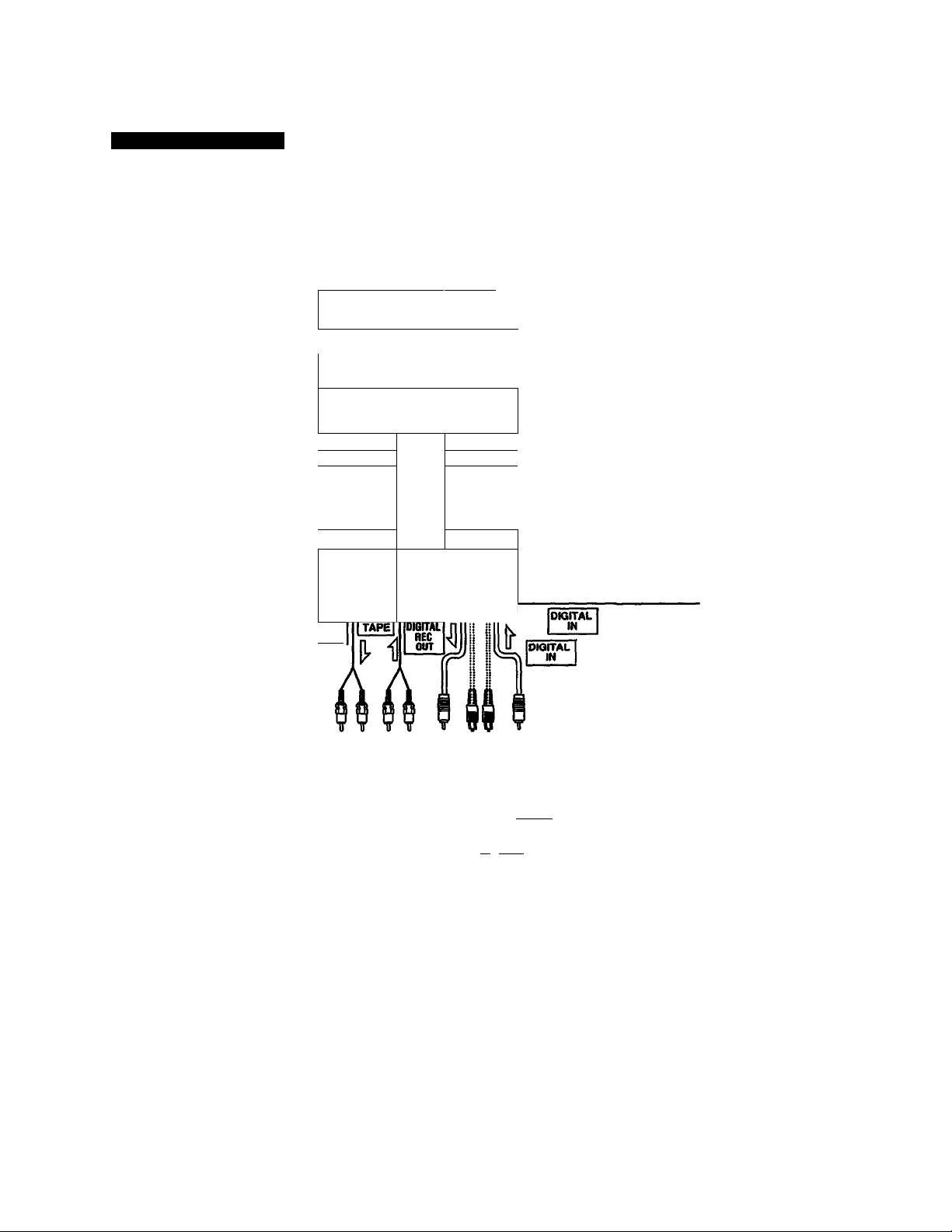
Connection Examples
If your amplifier is equipped with digital signal jacks
DIGITAL IN
UNEIN I
i\ n
If ^
DIGITAL
RECOUT
Amplifieil OUT
I REC OUT I
REC
CD player digital our
DAT deck
1__1
1 LINE OUT 1
1 TAPE, etc.
DIGITAL OUT
DIGITAL
IN
; Analog signal
: Digital signal
(coaxial cord or optical cable)
: Signal flow
A k
DTC-57ES
fipMTRO
PI i Slew
'IrFvSF
to a wall outlet
Note
If “COPY PROHIBIT” appears in the display window,
recording via digital-to-digital connection cannot be
performed.
In this case, connect the sound source equipment using
LINE IN and OUT jacks.
15
 Loading...