

Page 1

3-868-500-03 (1)
Digital Camcorder
Operating Instructions
Before operating the unit, please read this manual
thoroughly and retain it for future reference.
DSR-400L/400PL
DSR-400K/400PK
DSR-450WSL/450WSPL
© 2005 Sony Corporation
Page 2

Owner’s Record
CAUTION
The model and serial numbers are located on the top.
Record these numbers in the spaces provided below. Refer
to them whenever you call upon your Sony dealer
regarding this product.
Model No. Serial No.
WARNING
To prevent fire or shock hazard, do not
expose the unit to rain or moisture.
To avoid electrical shock, do not open the
cabinet. Refer servicing to qualified
personnel only.
AVERTISSMENT
Afin d’éviter tout risque d’incendie ou
d’électrocution, ne pas exposer cet
appareil à la pluie ou à l’humidité.
Afin d’écarter tout risque d’électrocution,
garder le coffret fermé. Ne confier
l’entretien de l’appareil qu’à un personnel
qualifié.
WARNUNG
Um Feuergefahr und die Gefahr eines
elektrischen Schlages zu vermeiden, darf
das Gerät weder Regen noch Feuchtigkeit
ausgesetzt werden.
Um einen elektrischen Schlag zu
vermeiden, darf das Gehäuse nicht
geöffnet werden. Überlassen Sie
Wartungsarbeiten stets nur qualifiziertem
Fachpersonal.
Danger of explosion if battery is incorrectly replaced.
Replace only with the same or equivalent type
recommended by the manufacturer.
Dispose of used batteries according to the manufacturer’s
instructions.
ADVARSEL!
Lithiumbatteri-Eksplosionsfare ved fejlagtig håndtering.
Udskiftning må kun ske med batteri af samme fabrikat og
type.
Levér det brugte batteri tilbage til leverandøren.
ADVARSEL
Lithiumbatteri - Eksplosjonsfare.
Ved utskifting benyttes kun batteri som anbefalt av
apparatfabrikanten.
Brukt batteri returneres apparatleverandøren.
VARNING
Explosionsfara vid felaktigt batteribyte.
Använd samma batterityp eller en likvärdig typ som
rekommenderas av apparattillverkaren.
Kassera använt batteri enligt gällande föreskrifter.
VAROITUS
Paristo voi räjähtää jos se on virheellisesti
asennettu.
Vaihda paristo ainoastaan laitevalmistajan
suosittelemaan tyyppiin.
Hävitä käytetty paristo valmistajan ohjeiden
mukaisesti.
For customers in the USA
This equipment has been tested and found to comply with
the limits for a Class A digital device, pursuant to Part 15
of the FCC Rules. These limits are designed to provide
reasonable protection against harmful interference when
the equipment is operated in a commercial environment.
This equipment generates, uses, and can radiate radio
frequency energy and, if not installed and used in
accordance with the instruction manual, may cause
harmful interference to radio communications. Operation
of this equipment in a residential area is likely to cause
harmful interference in which case the user will be
required to correct the interference at his own expense.
2
Page 3
You are cautioned that any changes or modifications not
expressly approved in this manual could void your
authority to operate this equipment.
The shielded interface cable recommended in this manual
must be used with this equipment in order to comply with
the limits for a digital device pursuant to Subpart B of Part
15 of FCC Rules.
For the customers in Europe
This product with the CE marking complies with the EMC
Directive (89/336/EEC) issued by the Commission of the
European Community.
Compliance with this directive implies conformity to the
following European standards:
• EN55103-1: Electromagnetic Interference (Emission)
• EN55103-2: Electromagnetic Susceptibility (Immunity)
This product is intended for use in the following
Electromagnetic Environment(s):
E1 (residential), E2 (commercial and light industrial), E3
(urban outdoors) and E4 (controlled EMC environment,
ex. TV studio).
Pour les clients européens
Ce produit portant la marque CE est conforme à la
Directive sur la compatibilité électromagnétique (EMC)
(89/336/CEE) émise par la Commission de la
Communauté européenne.
La conformité à cette directive implique la conformité aux
normes européennes suivantes:
• EN55103-1: Interférences électromagnétiques
(émission)
• EN55103-2: Sensibilité électromagnétique (immunité)
Ce produit est prévu pour être utilisé dans les
environnements électromagnétiques suivants:
E1 (résidentiel), E2 (commercial et industrie légère),
E3 (urbain extérieur) et E4 (environnement EMC contrôlé,
ex. studio de télévision).
For the customers in the USA and Canada
RECYCLING LITHIUM-ION BATTERIES
Lithium-Ion batteries are recyclable.
You can help preserve our environment by
returning your used rechargeable batteries
to the collection and recycling location
nearest you.
For more information regarding recycling
of rechargeable batteries, call toll free 1-800-822-8837, or
visit
http://www.rbrc.org/
Caution: Do not handle damaged or leaking lithium-ion
batteries.
Pour les utilisateurs aux Etats-Unis et au Canada.
RECYCLAGE DES ACCUMULATEURS AUX IONS DE
LITHIUM
Les accumulateurs aux ions de lithium
sont recyclables.
Vous pouvez contribuer à préserver
l’environnement en rapportant les piles
usées dans un point de collection et
recyclage le plus proche.
Pour plus d’informations sur le recyclage des
accumulateurs, téléphonez au numéro gratuit
1-800-822-8837 (Etats-Unis et Canada uniquement), ou
visitez http://www.rbrc.org/
Avertissment: Ne pas utiliser des accumulateurs aux ions
de lithium qui sont endommagés ou qui fuient.
Für Kunden in Europa
Dieses Produkt besitzt die CE-Kennzeichnung Und erfüllt
die EMV-Richtlinie (89/336/EWG) der EG-Kommission.
Angewandte Normen:
• EN55103-1: Elektromagnetische Verträglichkeit
(Störaussendung)
• EN55103-2: Elektromagnetische Verträglichkeit
(Störfestigkeit),
für die folgenden elektromagnetischen Umgebungen: E1
(Wohnbereich), E2 (kommerzieller und in beschränktem
Maße industrieller Bereich), E3 (Stadtbereich im Freien)
und E4 (kontrollierter EMV-Bereich, z.B. Fernsehstudio).
For the customers in Taiwan only
Voor de Klanten in Nederland
Gooi de batterij niet weg maar lever deze in
als klein chemisch afval (KCA).
Für Kunden in Deutschland
Entsorgungshinweis: Bitte werfen Sie nur entladene
Batterien in die Sammelboxen beim Handel oder den
Kommunen. Entladen sind Batterien in der Regel dann,
wenn das Gerät abschaltet und signalisiert “Batterie leer”
oder nach längerer Gebrauchsdauer der Batterien “nicht
mehr einwandfrei funktioniert”. Um sicherzugehen,
kleben Sie die Batteriepole z.B. mit einem Klebestreifen
ab oder geben Sie die Batterien einzeln in einen
Plastikbeutel.
Note about laser beams
Laser beams can damage the CCDs of this camcorder. In
environments where laser beams are used, be careful to
prevent the laser beams from striking the surfaces of the
CCDs.
3
Page 4

Table of Contents
Chapter 1 Overview
Product Configurations .............................6
Features ......................................................7
Camera features ............................................7
VTR features.................................................8
Location and Function of Parts ................9
Front view.....................................................9
Right side view ...........................................10
Left and upper view....................................15
Rear view....................................................17
Lens.............................................................19
DXF-801 Viewfinder..................................20
Status display on the viewfinder screen......21
Status display on the LCD monitor ............23
Using the CD-ROM Manual......................25
CD-ROM system requirements ..................25
Preparations ................................................25
Reading the CD-ROM manual ...................25
Using a Video Light.................................. 33
Preparing Audio Input System................ 34
Using the supplied microphone ................. 34
Using an external microphone ................... 34
Using a wireless microphone system......... 35
Connecting line input audio equipment..... 37
Connecting the Remote Control Unit
(DSR-450WS/450WSP only).............. 37
Chapter 3 Connections
Connecting a Monitor .............................. 40
Using an i.LINK Connection.................... 41
Settings required for an i.LINK
connection ........................................ 41
Making a backup of the images being
recorded............................................ 41
Using the camcorder as a feeder................ 42
Other Connections................................... 44
Connecting a number of camcorders ......... 44
Chapter 4 Recording and Playback
Chapter 2 Preparation
Attaching and Replacing the Lithium
Battery ................................................27
Preparing the Lens...................................28
Mounting the lens .......................................28
Adjusting the flange focal length................28
Preparing a Power Supply.......................29
Using a battery pack ...................................29
Using an AC adaptor ..................................29
Avoiding breaks in operation due to an
exhausted battery...............................30
Adjusting the Viewfinder .........................30
Fitting the viewfinder .................................30
Adjusting the viewfinder position ..............31
Adjusting the eyepiece focus and the screen
(brightness, contrast, and outline
emphasis)...........................................31
Attaching a 5-inch electronic viewfinder ...31
Using the Shoulder Strap ........................32
Adjusting the Shoulder Pad Position..... 32
Fitting to a Tripod.....................................33
Inserting a Cassette ................................. 45
Basic Procedure for Shooting ................46
Recording .................................................47
Usable cassettes ......................................... 47
Selecting the recording format................... 49
Adjusting the black balance/white
balance.............................................. 50
Setting the electronic shutter ..................... 52
Adjusting the iris........................................ 55
Adjusting the audio level ........................... 57
Setting the time data .................................. 57
Setting for special shooting cases .............. 60
Back Space Editing.................................. 61
Starting back space editing at any tape
position ............................................. 61
Using the edit search function while back
space editing..................................... 62
Time-Lapse Video (Interval Rec).............63
Making settings before shooting................ 63
Shooting and recording in Interval Rec
mode ................................................. 63
4
Page 5

Recording Analog Composite Signals
(with a CBK-SC01 Installed-
DSR-450WS/450WSP only) ...............64
Playing and Checking Recorded
Contents.............................................65
Checking the recorded contents immediately
after shooting — Recording Review.65
Checking the recording on the color video
monitor ..............................................65
Setting the date/time of the internal
clock ............................................... 105
Assigning functions to ASSIGN
switches .......................................... 106
Selecting the lens file............................... 106
Selecting the aspect ratio
(DSR-450WS/450WSP only)......... 106
Setting the CCD scan mode
(DSR-450WS/450WSP only)......... 107
Chapter 5 Menu Displays and
Detailed Settings
Menu Organization and Operation.......... 66
The TOP menu............................................73
Menu list .....................................................75
Displaying menus .......................................93
Basic menu operations................................93
Using the USER menu (Example of the
menu operation).................................94
Editing the USER menu..............................95
Resetting USER menu settings to the
standard settings ................................98
Setting the Status Display on the
Viewfinder Screen and the LCD
Monitor ...............................................98
Selecting the display items .........................98
Display modes and setting change
confirmation/adjustment progress
messages............................................99
Setting the marker display ........................100
Setting the viewfinder...............................100
Recording shot data superimposed on the
color bars.........................................101
Setting the shot ID ....................................101
Displaying the status confirmation
windows ..........................................102
Adjustments and Settings from
Menus ...............................................103
Setting gain values for the GAIN switch
positions ..........................................103
Selecting the output signals
(DSR-450WS/450WSP only)..........104
Setting the color temperature manually....104
Specifying an offset for the auto white
balance setting.................................105
Chapter 6 Saving and Loading the
User Setting Data
Saving and Loading User Files............. 109
Handling the “Memory Stick” ................. 109
Saving USER menu data (user file) to
the “Memory Stick” ....................... 110
Loading saved data from
a “Memory Stick”........................... 112
Saving and Loading Scene Files .......... 113
Saving a scene file ................................... 113
Loading scene files .................................. 115
Resetting the settings of the camcorder
to the standard settings ................... 116
Displaying a File-Related Menu Page
When Inserting a “Memory Stick” .117
Chapter 7 Appendix
Important Notes on Operation .............. 118
Characteristics of CCD sensors ............... 119
Maintenance ...........................................120
Cleaning the video heads ......................... 120
Replacing the video heads ....................... 120
Replacing other parts ............................... 120
Using the auto-check function ................. 120
About i.LINK ...........................................122
About a “Memory Stick”........................ 123
Operation Warnings............................... 125
Troubleshooting..................................... 128
Specifications......................................... 130
Chart of Optional Components and
Accessories ..................................... 133
Glossary.................................................. 135
Index........................................................ 137
5
Page 6

Chapter 1 Overview
Overview
Product Configurations
The DSR-400/450WS Digital Camcorder series is made
up of the DSR-400K/400PK, DSR-400L/400PL, and
DSR-450WSL/450WSPL models depending on the
product configuration, as shown in the figure below.
The camcorders comprise both NTSC and PAL versions.
The operation of the basic camcorder is the same in all
cases.
DSR-400L/400PL, DSR-450WSL/450WSPL
Chapter
DSR-400K/400PK
DXF-801
Viewfinder *
DSR-400/400P/450WS/450WSP
Camcorder
* Part number A-8279-329-A
Microphone
Shoulder strap
VCT-U14
Tripod Adaptor
Test chart for flange focal
length adjustment
• Lens mount cap
• Operating Instructions
VCL-917BY Zoom Lens
6
Product Configurations
Page 7

Features
The DSR-400/400P DVCAM* digital camcorder is
equipped with a
2/3-inch type Power HAD
an aspect ratio of 4:3. The DSR-450WS/450WSP
DVCAM digital camcorder is equipped with a
type Power HAD EX CCD with a wide-screen aspect ratio
of 16:9. In addition to the same main features, functions,
and operation method of previous models, these new
camcorders provide superior camera functionality.
* “DVCAM” and “Power HAD” are registered trademarks of Sony
Corporation.
Camera features
2/3-inch Power HAD EX CCDs
The three high-sensitivity, low-smear 2/3-inch Power HAD
EX CCDs provide high image quality putting this camera
at the top of its class for a standard NTSC/PAL definition
camcorder.
• Smear: –140 dB
• Sensitivity: F11 (3200K, 2000lx)
• S/N ratio: 65 dB (DSR-400/450WS), 63 dB (DSR-400P/
450WSP)
The DSR-450WS/450WSP allows you to switch between
a 16:9 aspect-ratio wide image and a 4:3 aspect-ratio
standard image.
2.5-inch color LCD monitor
A 2.5-inch color LCD monitor is mounted on the side of
the camcorder. You can check the video image during both
recording and playback. Also, the LCD monitor angle can
be adjusted freely to make high-angle and low-angle
recording easier. The time code and an audio level meter
can also be displayed on the LCD monitor.
Stylish design
The basic design of the camcorder has been improved.
Stylish angles and an attractive finish for the VTR section
are combined with a wide, easy-to-use connector section
on the back of the camcorder.
Adjustable shoulder pad
The camcorder is equipped with an adjustable shoulder
pad that makes it possible to adjust the position of the
camcorder to shoot from a stable position regardless of the
body size and shooting style of the camera operator.
Recording in progressive scan mode
(DSR-450WS/450WSP only)
You can record in a progressive scan mode of 30 PsF
(DSR-450WS) or 25 PsF (DSR-450WSP). (The video
image is recorded as an interlaced scan signal (60i (DSR450WS) or 50i (DSR-450WSP)).) Also for the DSR450WS, a 24P mode makes it possible to record film-like
*
EX CCD with
2/3-inch
images. (The video image is recorded as an interlaced scan
signal (60i) by 2-3 pull-down conversion.)
For details on recording in progressive scan mode, see
“Setting the CCD scan mode (DSR-450WS/450WSP
only)” on page 108.
ASSIGN (Assignable) switches
Assignable switches provided on the side panel and on the
top of the grip, respectively, can be assigned to functions
such as ATW, VTR start/stop, etc., to suit your needs.
When shooting, these functions can then be called up
instantly.
Scene file
You can save various settings for shooting a particular
scene as a scene file in the internal memory of the
camcorder. Loading the scene file, you can quickly
recreate the same setup conditions suitable for shooting a
particular scene.
“Memory Stick” slot
The camcorder is equipped with a “Memory Stick” slot.
When using the scene file function, you can save menu
settings on a “Memory Stick” and quickly recall them
when necessary. Also, when two or more camcorders are
used for shooting, the settings of the first camcorder can be
copied to the others via the “Memory Stick”, making color
matching easier.
Programmable gain
The value of gain that is assigned to the setting (H/M/L) of
the GAIN switch can be selected from –3dB, 0dB, 3dB,
6dB, 9dB, 12dB, 18dB, 24dB, 30dB, and 36dB.
Electric CC filter
The CC filter that was previously paired with the ND filter
has been eliminated, so the ND filter is now the
camcorder’s only optical filter and this makes operation of
the camcorder easier. With the wide-band white balance
amplifier of this camcorder, the white balance can be
adjusted in a wide range of color temperatures without an
optical CC filter.
Auto-tracing white balance (ATW)
This function automatically traces the white balance,
which constantly changes as lighting conditions change.
Auto-tracing white balance is especially useful when there
is no time to manually adjust the white balance, or when
shooting moves between indoor and outdoor locations.
A variety of shutter functions
• Electronic shutter
The high-performance electronic shutter allows you to
record a video image at a high resolution even when
shooting fast-moving objects.
•ECS
The ECS (Extended Clear Scan) mode allows you to adjust
the shutter speed more precisely. You can set shutter speed
Chapter 1 Overview
Features
7
Page 8

to a value close to the scan frequency of a computer
display, so that the horizontal band and flicker that appear
when recording a computer display can be reduced.
• Slow shutter (DSR-450WS/450WSP only)
A slow shutter function allows you to set the exposure time
longer than 1 frame. By doing so, sensitivity is improved
Chapter 1 Overview
dramatically. Also, dreamlike images using the
afterimages can be shot.
Setting of multiple gamma curves
(DSR-450WS/450WSP only)
Setting of multiple gamma curves is possible using a
menu. You can shoot using image tones that suit your
purpose, such as making film-like images.
Dual zebra pattern display
Two types of zebra patterns can be set at independent
display levels. They can be used in various ways; for
example, one can be set to the brightness level of the main
objects, and the other can be set to a higher brightness
level.
Video light connector
A video light connector (maximum 50 W) and control
switch are provided. You can set the switch to turn the light
on and off automatically as you start and stop the VTR.
Remote control connectors
(DSR-450WS/450WSP only)
Instead of making settings using menus, detailed settings
of the camcorder can be made using an optional RM-B150
or B750 remote control unit connected to the camcorder.
High-capacity BP-GL95 Battery Pack
The camcorder supports the information battery function.
When using a BP-GL65/GL95 Battery Pack, more
accurate and detailed information on remaining battery
power is displayed in the viewfinder.
High-functionality DXF-801 Viewfinder
The supplied DXF-801 Viewfinder has the following
features.
• High resolution (600 TV lines of horizontal resolution)
• A DISPLAY switch that can turn the character display
on and off
• A light for the lens control elements
• A large-diameter eye cup with a flip-up mechanism for
viewing with the eye apart from it
• A peaking potentiometer for vertical and horizontal
detail control
• A tough, die-cast aluminium body
• Automatic aspect ratio switching between 16:9 and 4:3
(DSR-450WS/450WSP only)
VTR features
Standard-size and mini-size DVCAM cassettes
Equipped with a tape drive with an original Sony
mechanism, this camcorder can use both standard-size
DVCAM cassettes (a standard cassette that can record a
maximum of 180 minutes in DVCAM mode) and minisize DVCAM cassettes (a small cassette that is convenient
to carry and store). Both can be used without an adaptor.
Compatible with DV recording (SP mode)
In addition to recording in DVCAM mode, this camcorder
can record in the same DV mode that is widely available in
consumer-use camcorders. (Only recording in SP mode is
available. LP mode is not available for either recording or
playback.) Recording in DV format allows a longer
recording time, 270 minutes for a DVCAM 180-minute
tape. This helps to reduce tape-changing time and the risk
of missing important scenes when shooting a long event.
PCM digital audio
For tapes recorded in DVCAM mode, recording/playback
can be set to audio lock mode. You can choose between the
two-channel recording mode (with a sampling frequency
of 48 kHz) or the four-channel recording mode (with a
sampling frequency of 32 kHz, records only CH-1 and CH2 on this camcorder).
(i.LINK) DV OUT connector
This camcorder has an (i.LINK) DV OUT connector.
You can connect other DVCAM/DV recorders or i.LINK
(DV) compatible non-linear editing equipment supporting
a digital signal interface without degradation. Connecting
external VTR equipment allows you to back up recordings
to avoid missing any scenes by mistake. Also, you can set
the REC TRIGGER switch to suit your needs and you can
control the VTR sections of the camcorder and any
external equipment independently.
* “i.LINK” and are trademarks.
VBS video input signal (DSR-450WS/450WSP
only)
By installing an optional CBK-SC01 Composite Input
Board, the camcorder can input and record an external
analog video signal. This is useful for pool coverage, etc.
Interval Rec function
Using the Interval Rec function, you can create time-lapse
videos. This is useful for various specialized projects, such
as time-lapse recording of plant growth, etc.
*
8
Features
Page 9
Location and Function of Parts
Front view
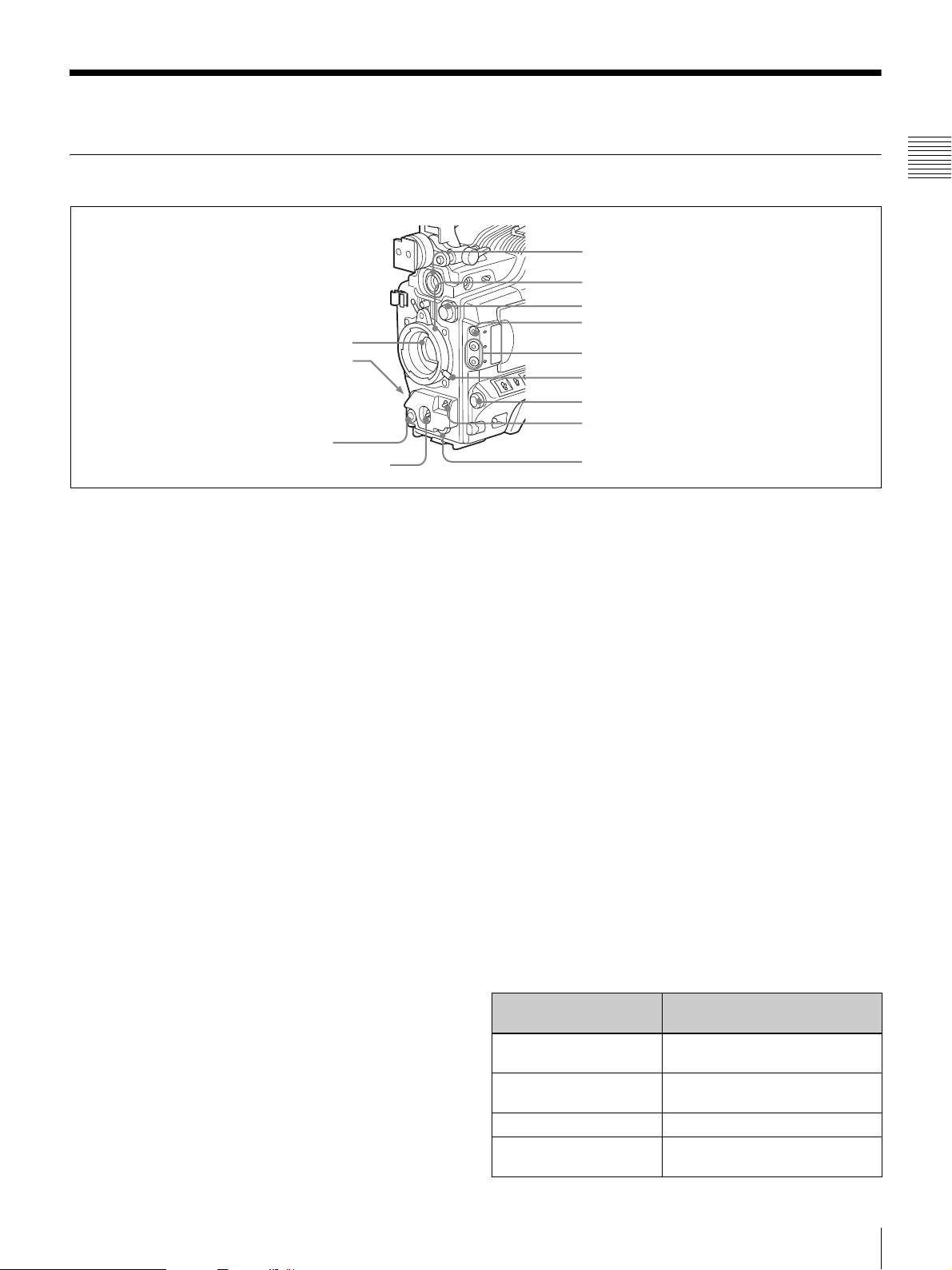
1 Lens mount cap
2 LENS connector
3 REC button
4 AUTO W/B BAL switch
a Lens mount cap
Remove by pushing up the lens locking lever (page 10).
When no lens is mounted, keep this cap fitted for
protection from dust.
b LENS connector (12-pin)
Connect the lens cable. Contact your Sony representative
for more information about the lens you can use.
c REC (recording start) button
Press to start recording. Press it again to stop recording.
The effect is exactly the same as that of the VTR button on
the lens. When the REC SWITCH function is assigned to
the ASSIGN switch on the FUNCTION 1 page of the
OPERATION menu, you can use the switch as the REC
button.
5 VF connector
6 Lens mount
7 FILTER selector
8 ZEBRA button
9 ASSIGN 1/2 switches
0 Lens locking lever
qa MENU knob
qs SHUTTER switch
qd AUDIO LEVEL knob
d AUTO W/B BAL (automatic white/black balance
adjustment) switch
Activates the white/black balance automatic adjustment
functions.
WHT: Adjusts the white balance automatically. If the
WHITE BAL switch
(page 11) is set to A or B, the
white balance setting is stored in the corresponding
memory.
BLK: Adjusts the black set and black balance
automatically.
e VF (viewfinder) connector (20-pin)
Connect the supplied DXF-801 Viewfinder.
f Lens mount (special bayonet mount)
Attach the lens.
Chapter 1 Overview
You can select the recording format for the video signal
from either DVCAM mode or DV-SP mode on the VTR
MODE page of the MAINTENANCE menu.
In the recording pause state, the camcorder waits for a
certain period of time in the standby-on mode and then
automatically switches to standby-off mode. This length of
the standby-on period with no operation can be set to
either 1 minute, 3 minutes, or 5 minutes on the VTR MODE
page of the MAINTENANCE menu.
g FILTER selector
Selects the most appropriate filter to match the light source
illuminating the subject. When this selector is used with
the display mode set to 3
(page 99), the new setting
appears on the viewfinder screen for about 3 seconds.
FILTER selector setting and examples of shooting
conditions
FILTER selector setting Examples of shooting
1 (CLEAR) Studio halogen lighting
2 (1/4 ND) Cloudy or rainy outdoor shooting,
3 (1/16 ND) Sunlight
4 (1/64 ND) To reduce the depth of field in
conditions
(incandescent)
or to reduce the depth of field*
sunlight
Location and Function of Parts
9
Page 10

* The range over which the subject is sharply in focus. Thus, “reducing the
depth of field” means that the range is reduced as well, and “increasing the
depth of field” means that it is increasing as well.
k MENU knob
Changes the page selection or a setting within the menu.
h ZEBRA button
Press to display a zebra pattern (diagonal stripes) in the
viewfinder screen.
Chapter 1 Overview
The zebra pattern is factory set to indicate picture areas
where the video level is approximately 70%. However, on
the VF SETTING page of the OPERATION menu, you
can change the setting so that areas where the video level
is 100% and above also displayed at the same time.
For details, see “Setting the viewfinder” on page 100.
i ASSIGN 1/2 switches
You can assign the desired functions on the FUNCTION 1
page of the OPERATION menu.
For details, see “Assigning functions to ASSIGN
switches” on page 106.
j Lens locking lever
After inserting the lens in the lens mount, rotate the lens
mount ring with this lever to lock the lens in position.
Right side view
For details about how to use the MENU knob, see “Basic
menu operations” on page 93.
l SHUTTER switch
Set to ON to use the electronic shutter. Flick to SEL to
switch the shutter speed or shutter mode setting within the
range previously set with the menu. When this switch is
operated, the new setting appears on the setting change/
adjustment progress message display area for about 3
seconds.
For details about the shutter speed and shutter mode
settings, see
“Setting the electronic shutter” on page 52.
m AUDIO LEVEL knob
Adjusts the channel 1 audio input level manually. You can
invalidate the setting of this knob in the F AUDIO VOL
item on the AUDIO page of the MAINTENANCE menu.
Front section
1 5600K button
2 LIGHT switch
3 OUTPUT/DCC switch
4 GAIN switch
5 POWER switch
a 5600K button
Press to lit the button and switch the standard color
temperature for shooting to 5600K. Use this button for
outdoor shooting in daytime or shooting under lighting
with higher temperature. While setting the wide-band
white balance, the button does not function.
b LIGHT switch
Determines how a video light connected to the LIGHT
connector
(page 16) is turned on and off.
6 MONITOR knob
7 ALARM knob
8 LCD monitor
9 MENU switch
0 WHITE BAL switch
AUTO: When the POWER switch of the video light is in
the on position, the video light is turned on
automatically while the camcorder is recording.
MAN: You can turn the video light on or off manually,
using its own switch.
Note
• When this switch is set to AUTO, at the beginning of the
recording, the picture is recorded even though the
lighting may fluctuate until the video light comes on. If
the beginning of the recording is important, you should
10
Location and Function of Parts
Page 11

set this switch to MAN. However, when using the
interval recording mode, the video light is automatically
turned on immediately before recording starts.
• To ensure proper operation of the video light, Sony
recommends the use of the battery pack BP-GL65,
BP-GL95, or BP-L60S with the camcorder.
g ALARM (alarm tone volume adjustment) knob
Controls the volume of the warning tone that is output via
the built-in speaker or earphones. Turning this knob to the
minimum setting mutes the alarm tone.
ALARM
Chapter 1 Overview
c OUTPUT /DCC (output signal/dynamic contrast
control) switch
Switches the video signal, which is output to the VTR part,
viewfinder, and video monitor from the camera part,
between the following two.
BARS: Outputs the color bar signal.
CAM: Outputs the video signal from the camera. When
this is selected, you can switch DCC
* DCC (Dynamic Contrast Control): Against a very bright background
with the iris opening adjusted to the subject, objects in the background will
be lost in the glare. The DCC function will suppress the high intensity and
restore much of the lost detail and is particularly effective in the following
cases.
• Shooting people in the shade on a sunny day
• Shooting a subject indoors, against a background through a window
• Any high contrast scene
OUTPUT: BARS, DCC: OFF
A color bar signal is output and the DCC circuit does not
operate. Use this setting to adjust the video monitor, to
record the color bar signal, etc.
OUTPUT: CAM, DCC: OFF
OUTPUT
DCC
The video signal from the camera is output, and
the DCC circuit does not operate.
CAMBARS
OUTPUT: CAM, DCC: ON
The video signal from the camera is output, and
the DCC circuit operates.
ONOFF
*
on and off.
d GAIN switch
Switches the gain of the video amplifier to match the
lighting conditions during shooting. The gains
corresponding to the L, M, and H settings can be selected
in the menu. (The factory settings are L = 0 dB, M = 9 dB,
and H = 18 dB.)
When this switch is adjusted, the new setting appears on
the setting change/adjustment progress message display
area of the viewfinder screen for about 3 seconds.
For details, see “Setting gain values for the GAIN switch
positions” on page 103.
e POWER switch
Turns the main power supply on and off.
f MONITOR (monitor volume adjustment) knob
Controls the volume of the sound other than the warning
tone that is output via the built-in speaker or earphones.
Turning this knob to the minimum setting mutes the audio
output.
Minimum Maximum
h LCD monitor
Displays VTR-related warnings, remaining battery
capacity, remaining tape capacity, audio levels, time data,
and so on.
For details, see “Status display on the LCD monitor” on
page 23.
i MENU switch
When flicking toward ON, the USER menu is displayed.
When flicking toward STATUS, the status of the
camcorder (of current settings) is displayed.
For details, see “Displaying menus” on page 93.
j WHITE BAL (white balance memory) switch
Controls adjustment of the white balance.
PRST: Adjusts the color temperature to the preset value.
Use this setting when you have no time to adjust the
white balance.
A or B: When the AUTO W/B BAL switch (page 9) is
pushed to WHT, the white balance is automatically
adjusted according to the current position of the
FILTER selector
(page 9), and the adjusted value is
stored in either memory A or memory B. There are
two memories for each CC filter, allowing a total of
eight adjustments to be stored. When this switch is set
to A or B, the camcorder automatically adjusts itself
to the stored value corresponding to the current
settings of this switch and the FILTER selector.
You can use the AUTO W/B BAL switch even when
*
is in use.
ATW
B (ATW): When this switch is set to B and WHITE
SWITCH <B> is set to ATW on the FUNCTION 2
page of the OPERATION menu, ATW is activated.
When this switch is adjusted, the new setting appears
on the setting change/adjustment progress message
display area of the viewfinder screen for about 3
seconds. You can assign the ATW function to the
ASSIGN switch on the FUNCTION 1 page of the
OPERATION menu.
For details about how to assign the function to the ASSIGN
switches, see
“Assigning functions to ASSIGN switches”
on page 106.
* ATW (Auto Tracing White Balance): The white balance of the picture
being shot is adjusted automatically for varying lighting conditions.
Location and Function of Parts
11
Page 12
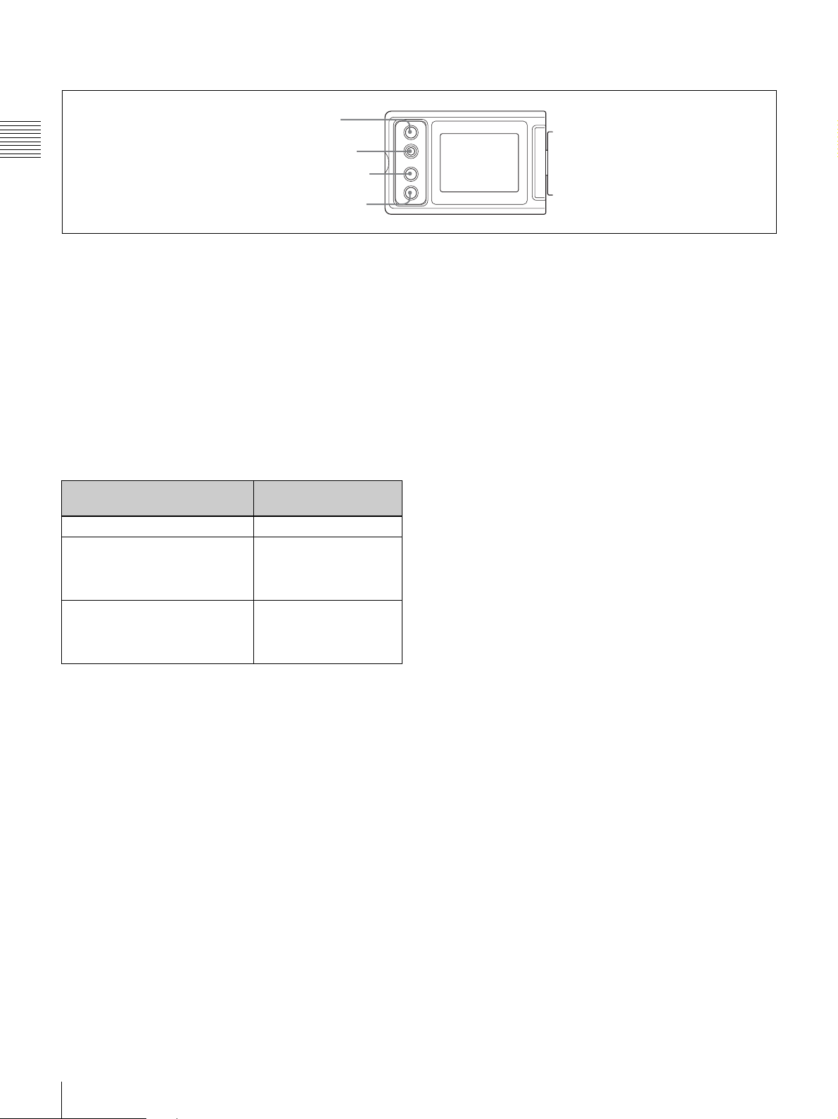
Left side of the LCD monitor
1 LCD button
Chapter 1 Overview
2 RESET button
3 DISPLAY button
4 DISP SEL button
a LCD button
Controls the LCD monitor. Each time pressing this button,
the setting changes as follows.
L: The LCD monitor is adjusted for viewing indoors.
H: The LCD monitor is adjusted for viewing outdoors.
OFF: The LCD monitor is turned off.
b RESET (counter reset) button
Resets the display of the time data when the LCD monitor
display is set to STATUS with the DISP SEL button.
According to the settings of the PRESET/REGEN/
CLOCK switch
(page 14) and the F-RUN/SET/R-RUN
switch (page 14), resets the display as follows.
Settings of the button and the
switch
DISPLAY button: COUNTER Counter to 0:00:00
DISPLAY button: TC
PRESET/REGEN/CLOCK
switch: PRESET
F-RUN/SET/R-RUN switch: SET
DISPLAY button: U-BIT
PRESET/REGEN/CLOCK
switch: PRESET
F-RUN/SET/R-RUN switch: SET
To reset
Time code to
00:00:00:00
User bit data* to 00 00
00 00
d DISP SEL (display selection) button
Each time pressing this button, the display in the LCD
monitor changes as follows.
CHAR: Displays video with superimposed text. With the
MENU switch set to STATUS, also display
camcorder status indications similar to those
displayed in the viewfinder.
MONI: Displays video without superimposed text.
STATUS: Displays counter, warnings, audio levels, etc.
* One of the time code bits recorded on a tape can be used to record the
necessary information for the user.
For details, see “Setting the time data” on page 57.
c DISPLAY (counter display toggle) button
Each time this button is pressed, the counter display
section changes as follows. This setting is activated only
when the LCD monitor display is set to STATUS with the
DISP SEL button.
COUNTER: Displays the elapsed recording/playback
time.
TC: Displays time code.
U-BIT: Displays user bit data.
12
Location and Function of Parts
Page 13
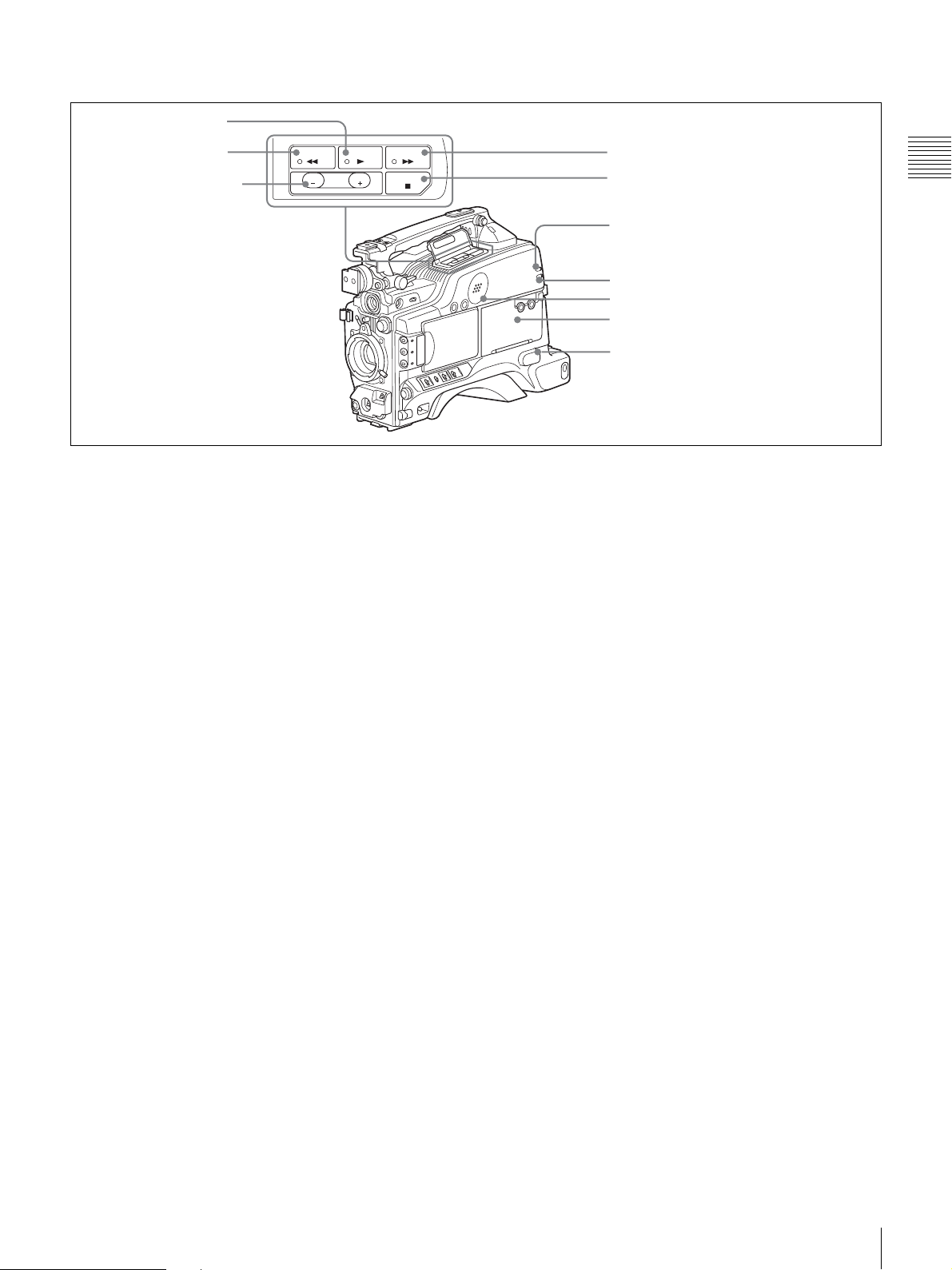
Rear section
1 PLAY button
and indicator
2 REW button
and indicator
3 EDIT SEARCH
+FWD/–REV
buttons
REW PLAY F FWD
REV
EDIT
SEARCH
FWD
STOP
4 F FWD button and indicator
5 STOP button
6 WARNING indicator
7 TAPE indicator
8 Built-in speaker
9 AUDIO adjustment cover
0 EARPHONE jack
Chapter 1 Overview
a PLAY button and indicator
Press to view a playback image using the viewfinder or a
LCD monitor. The indicator lights during playback.
Pressing this button again during playback pauses the
playback, showing a still image. At this time, the indicator
flashes. This camcorder is capable of color-image search at
approximately nine-times (NTSC system) or eleven-times
(PAL system) normal playback speed, making it easy to
check recorded material. To use the color-image search,
press and hold the REW or F FWD button during
playback. While the button is pressed, the PLAY indicator
and the REW or F FWD indicator light.
b REW button and indicator
Rewinds the tape. The indicator lights while the tape is
being rewound.
c EDIT SEARCH +FWD/–REV buttons
Press these buttons in recording pause mode or in stop
mode to find the next recording start point quickly. You
can search in playback while pressing either of these
buttons, or you can search by frame when pressing the
button and releasing it immediately. If you do not operate
the camcorder for about three seconds after releasing the
buttons, the camcorder will enter the REC standby mode at
the point where the buttons were released.
d F FWD button and indicator
Fast forwards the tape. The indicator lights while the tape
is being fast forwarded.
e STOP button
Stops playing, rewinding, or fast forwarding the tape.
For details about the meaning of the lights displayed, see
“Operation Warnings” on page 125.
g TAPE indicator
Lights up as below depending on the situation.
Continuous: When the cassette is in the camcorder.
Blinking: While the cassette is loading or ejecting.
Lights-out: When the cassette is not in the camcorder.
h Built-in speaker
The speaker can be used to monitor E-E* sound during
recording, and playback sound during playback. The
speaker also sounds alarms to reinforce visual warnings.
If you connect earphones to the EARPHONE jack, the
speaker is automatically muted.
* E-E: Abbreviation of “Electric-to-Electric.” In E-E mode, video and audio
signals input to the camcorder are output after passing through internal
electric circuits only. This can be used to check input signals.
For information about alarms, see “Operation Warnings”
on page 125.
i AUDIO adjustment cover
Open to reveal the audio setting switches (page 14) and
make audio adjustments.
j EARPHONE jack (monaural)
Plugging earphones, and you can monitor the E-E sound
during recording and playback sound during playback.
When an alarm is indicated, you can hear the alarm sound
through the earphones. Plugging earphones into the jack
automatically cuts off the sound from built-in speaker.
f WARNING indicator
Lights up or blinks when an abnormality occurs in the
VTR section.
Location and Function of Parts
13
Page 14
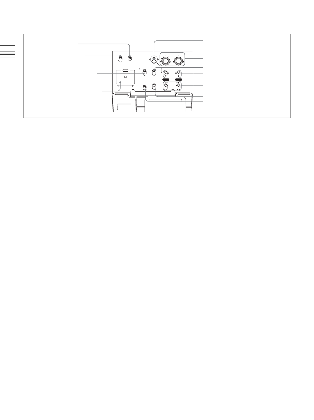
Operation panel under the AUDIO adjustment cover
1 MONITOR OUT
CHARACTER switch
Chapter 1 Overview
2 MONITOR SELECT
switch
CH-1
ON
MIX
OFF
CH-2
MONITOR
MONITOR OUT
SELECT
CHARACTER
3 PRESET/REGEN/CLOCK
switch
LITHIUM BATT
4 Lithium battery compartment
a MONITOR OUT (monitor output) CHARACTER
switch
Selects to superimpose text information on the monitor
output.
b MONITOR SELECT (audio monitor selection)
switch
Selects audio output via the built-in speaker or earphones.
CH-1: Channel 1 audio
MIX: Mixed audio (channels 1 and 2)
CH-2: Channel 2 audio
c PRESET/REGEN (regeneration)/CLOCK switch
Selects whether to set a new time code or to utilize the
existing time code.
PRESET: Records a new time code.
REGEN: Records time code continuous with the existing
time code recorded on the tape. Regardless of the
setting of the F-RUN/SET/R-RUN switch, the
camcorder operates in R-RUN mode.
CLOCK: Records time code synchronized to the internal
clock. Regardless of the setting of the F-RUN/SET/RRUN switch, the camcorder operates in F-RUN mode.
d Lithium battery compartment
Attach the supplied CR2032 Lithium Battery.
PRESET
REGEN
CLOCK
FRONT MIC
LOW OUT
ON
OFF
5 Arrow key
AUDIO LEVEL
6 AUDIO LEVEL controls
7 F-RUN/SET/R-RUN switch
8 AUDIO SELECT switches
9 AUDIO IN switches
REC
TRIGGER
F-RUN
SET
R-RUN
PARALLEL
INT ONLY
EXT ONLY
AUTO
MANUAL
AUDIO SELECT
CH-1 CH-1
AUDIO IN
FRONT
WRR
REAR
0 REC TRIGGER switch
qa FRONT MIC LOW CUT switch
when the AUDIO SELECT (CH-1/CH-2) switches (see
below) are set to MANUAL.
g F-RUN/SET/R-RUN (free run/set/recording run)
switch
Selects the operating mode for the internal time code
generator. The operating mode is set as explained below,
depending on the position of the switch.
F-RUN: Time code keeps advancing, regardless of the
operating state of the VTR. Use this setting when
synchronizing the time code with an external time
code.
SET: Sets the time code or user bits.
R-RUN: The time code value advances only during
recording. Use this setting to have a consecutive time
code on the tape.
For details, see “To set the time code” on page 57 and “To
set the user bits” on page 58.
h AUDIO SELECT (CH-1/CH-2) (audio channel 1/2
adjustment method selection) switches
Select the audio level adjustment method for each of audio
channels 1 and 2.
AUTO: Automatic adjustment
MANUAL: Manual adjustment
Details on how to attach the lithium battery, see
“Attaching and Replacing the Lithium Battery” on page
27.
e Arrow key
Sets the time code and the user bit. Push the key towards
left or right so that the digit you want to change flashes.
Pushing the key upward increases the value of the flashing
digit, and pushing it downward decreases the value.
f AUDIO LEVEL (CH-1/CH-2) (audio channel 1/2
recording level) controls
If the audio is input via the AUDIO IN CH-1/CH-2
connectors, adjusts the audio levels of channels 1 and 2
14
Location and Function of Parts
Page 15

i AUDIO IN (CH-1/CH-2) (audio channel 1/2 input
selection) switches
Select the audio input signals to be recorded on audio
channels 1 and 2. The audio input is sourced as explained
below based on the position of the switches.
FRONT: The microphone connected to the MIC IN (+48
V) connector
(page 16)
WRR: A WRR-855 UHF Synthesized Tuner Unit (not
supplied)
REAR: Audio equipment connected to the AUDIO IN
CH-1/CH-2 connectors
(page 18)
The following settings can be made on the AUDIO page of
the MAINTENANCE menu.
• Audio recording format
Select either Fs48K or 32K.
• Audio reference level
Select either –12 dB or –20 dB (DSR-400/450WS), –12
dB or –18 dB (DSR-400P/450WSP).
Left and upper view
• Audio fade-in/fade-out
Select either ON or OFF.
j REC TRIGGER (external VTR trigger) switch
Sets the function of the REC button on the camcorder or
the VTR button on the lens when an external VTR is
connected to the
(i.LINK) DV OUT connector (page
18). Set this switch to INT ONLY when you need to do cut
editing or dubbing using the (i.LINK) DV OUT
connector.
PARALLEL: Operates both internal and external VTRs
simultaneously.
INT ONLY: Operates the internal VTR only. External
VTR operation is performed locally.
EXT ONLY: Operates the external VTR only.
k FRONT MIC LOW CUT switch
Set to ON to insert a high-pass filter in the microphone
circuit, reducing wind noise. Normally leave the switch in
the OFF position.
Chapter 1 Overview
Front section
1 Accessory shoe
2 ASSIGN 3/4 switches
3 Viewfinder front-to-
back position locking
knob
a Accessory shoe
Attach an optional accessory such as a video light (page
33).
4 Shoulder strap fitting
5 Viewfinder left-to-right positioning ring
6 Viewfinder fitting shoe
7 LIGHT connector
8 MIC IN connector
9 Fitting for optional microphone
holder
c Viewfinder front-to-back position locking knob
Loosen this knob to adjust the front-to-back position of the
viewfinder
(page 30).
b ASSIGN 3/4 switches
You can assign the desired functions on the FUNCTION 1
page of the OPERATION menu.
For details, see “Assigning functions to ASSIGN
switches” on page 106.
d Shoulder strap fitting
Attach the supplied shoulder strap (page 32).
e Viewfinder left-to-right positioning ring
Loosen this ring to adjust the left-to-right position of the
viewfinder
(page 30).
Location and Function of Parts
15
Page 16

f Viewfinder fitting shoe
Attach the DXF-801 Viewfinder.
g LIGHT (video light) connector (2-pin, female)
A video light with a maximum power consumption of 50
W, such as the Anton Bauer Ultralight 2 or equivalent can
Chapter 1 Overview
be connected
(page 33).
Rear section
1 Attachment shoe for large
viewfinder
h MIC IN (microphone input) (+48V) connector
(XLR type, 3-pin, female)
Connect the supplied microphone to this connector. A
microphone other than the one supplied may also be
connected as long as it can operate with power source
supplied by external equipment. The power (+48 V) is
supplied via this connector.
i Fitting for optional microphone holder
Fit an optional CAC-12 Microphone Holder (page 34).
4 EJECT switch and tape indicator
5 Cassette lid
6 Shoulder pad
2 GENLOCK IN connector
3 MONITOR OUT connector
a Attachment shoe for large viewfinder
Attach an optional electronic viewfinder (page 31).
b GENLOCK IN connector (BNC type)
Use for the following two purposes.
• For DSR-400/400P/450WS/450WSP: Inputs a
reference signal when the camcorder is to be genlocked
or when time code is to be synchronized with external
equipment. Use the GENLOCK page of the
MAINTENANCE menu to adjust the genlock H-phase
(phase of horizontal sync signal) and the sub-carrier
phase.
• For DSR-450WS/450WSP only: Inputs an external
video signal. Installing a CBK-SC01 Composite Input
Board allows you to record external analog composite
video signals input via this connector. Non-standard
video signals, such as VHS, cannot be recorded.
For details, see “Recording Analog Composite Signals
(with a CBK-SC01 Installed- DSR-450WS/450WSP only)”
on page 64.
7 TC IN connector
8 TC OUT connector
c MONITOR OUT connector
Outputs a composite video signal for a video monitor.
Depending on menu settings, menus, time code, and shot
data can be superimposed on the image on the monitor.
Like the VIDEO OUT connector
(page 18), this connector
can also be used to synchronize the time code of an
external VTR with the time code of the camcorder.
d EJECT switch and tape indicator (inside the
cassette lid)
Press to eject a cassette when the power is supplied to the
camcorder. The indicator lights up as below.
Continuous: When the cassette is in the camcorder.
Blinking: While the cassette is loading or ejecting.
Lights-out: When the cassette is not in the camcorder.
e Cassette lid
Slide the OPEN lever on the top of the camcorder to open
the lid. Press the side of the lid to close it.
16
Location and Function of Parts
Page 17
f Shoulder pad
You can move the shoulder pad forwards or backwards by
raising up the shoulder pad locking lever. Do this to ensure
the best balance when shooting with the camcorder on
your shoulder.
For details about how to adjust the pad, see “Adjusting the
Shoulder Pad Position” on page 32.
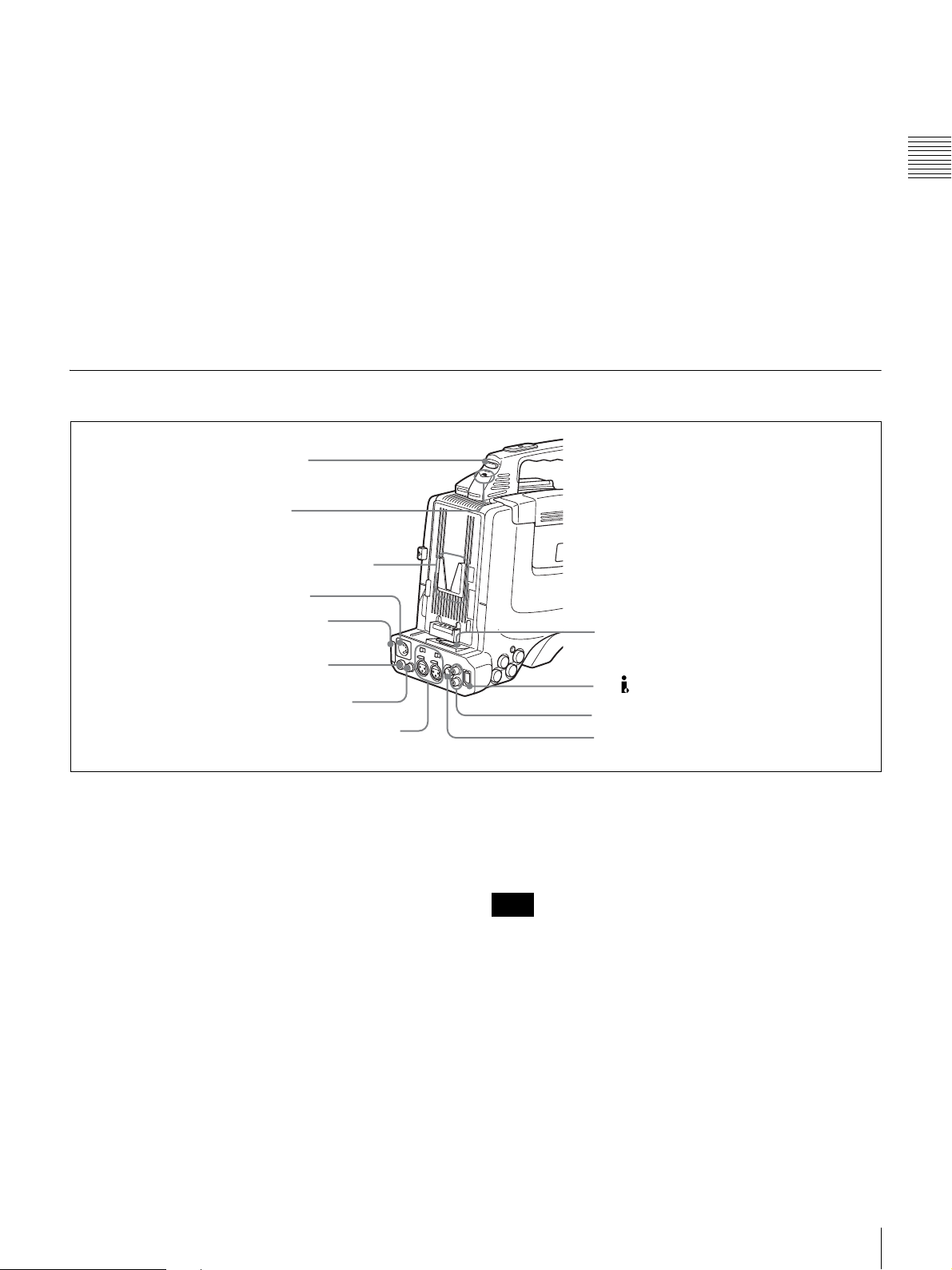
Rear view
1 TALLY indicator
2 TALLY switch
g TC IN (time code input) connector (BNC type)
To synchronize the time code of the camcorder to an
external time code, connect the camcorder to the external
equipment with the reference time code using this
connector.
Chapter 1 Overview
h TC OUT (time code output) connector (BNC type)
To synchronize the time code of an external VTR to that of
the camcorder, connect the camcorder to the reference
time code input connector of the external VTR using this
connector.
For details about the time code, see “To set the time code”
on page 57.
3 Battery attachment interface
4 DC IN connector
5 “Memory Stick” slot
6 REMOTE connector
(DSR-450WS/
450WSP only)
7 DC OUT 12 V connector
8 AUDIO IN CH-1/CH-2 connectors
and input selection switches
a TALLY (back tally) indicator (red)
Lights up during recording. It will not light if the TALLY
switch (see below) is set to OFF. This indicator also blinks
to indicate warnings
(page 13) in the same manner as the
REC/TALLY indicator in the viewfinder.
For details, see “Operation Warnings” on page 125.
b TALLY switch
Set to ON to activate the TALLY indicator (see above)
function.
c Battery attachment interface
Attach a BP-GL65/GL95/L60S battery pack. Furthermore,
by attaching an AC-DN10 AC Adaptor, you can operate
the camcorder using an AC power supply.
9 WRR connector
0 i.LINK (DV OUT) connector
qa AUDIO OUT CH-1/CH-2 connectors
qs VIDEO OUT connector (DSR-
450WS/450WSP only)
For details about how to attach the battery and AC
adaptor, see
“Preparing a Power Supply” on page 29. For
information about attaching a synthesized tuner, see
“Using a wireless microphone system” on page 35.
Note
For your safety, and to ensure proper operation of the
camcorder, Sony recommends the use of the following
battery packs: BP-GL65, BP-GL95, and BP-L60S.
d DC IN connector (XLR type, 4-pin, male)
To operate the camcorder using an AC power supply,
connect an AC-550 AC Adaptor with the DC output cable
supplied with the adaptor.
Location and Function of Parts
17
Page 18

e “Memory Stick” slot
Chapter 1 Overview
“Memory Stick”
access indicator
“Memory Stick”
Insert a “Memory Stick”. The “Memory Stick” access
indicator lights up when the “Memory Stick” is being
accessed for reading or writing.
For details about how to insert a “Memory Stick”, see “To
insert a “Memory Stick”” on page 109.
For details about the types of “Memory Stick”, see “About
a “Memory Stick”” on page 123.
Note
Do not remove a “Memory Stick” while the “Memory
Stick” access indicator is lit. Doing so may cause a loss of
data.
f REMOTE connector (8-pin) (DSR-450WS/
450WSP only)
Connect a RM-B150/B750 Remote Control Unit, which
makes it possible to control the camcorder remotely.
g DC OUT 12 V (DC power output) connector (4-pin,
female)
Supplies power for a WRR-861/862 UHF Synthesizer
Tuner (optional) (maximum 0.2 A).
Do not connect any equipment other than the UHF
synthesizer tuner.
h AUDIO IN CH-1/CH-2 (audio input channel 1/2)
connectors (XLR-3 pin, female) and input selection
switches
Connect other audio equipment or external microphone.
Set the input selection switches as shown below according
to the microphone or equipment.
MIC +48V ON (right position): For connecting to a 48 V
microphone
MIC (center position): For connecting any microphone
other than 48 V microphone
LINE (left position): For connecting an external audio
signal source such as a stereo amplifier
Note
If MIC +48V ON is selected for a microphone other than
48 V microphone, the microphone may be damaged.
i WRR connector (7-pin)
Connect a CA-WR855 Camera Adaptor with attached
WRR-855 UHF Synthesizer Tuner.
For details, see “Using a wireless microphone system” on
page 35.
j (i.LINK) DV OUT connector (6-pin, IEEE1394
compliant)
Connect to a device supporting the DV format or a
computer, using i.LINK cable (DV cable).
Notes
• If video and audio signals from an external device
connected to the
(i.LINK) DV OUT connector are not
output, disconnect the i.LINK cable (DV cable) and then
reconnect it, making sure that it is firmly seated.
• When you connect the camcorder and other equipment,
such as a hard disk drive, with an i.LINK interface to a
computer with i.LINK connectors, turn off the power of
the computer, the other equipment, and the camcorder
before connecting them using the i.LINK cable (DV
cable). If a bus-powered type* hard disk drive or similar
equipment is connected while the computer is powered
on, electric current flows into the camcorder because of
the high voltage caused by the load shift of the computer
power, and this may cause a malfunction.
* Equipment that can be powered through i.LINK cable (DV cable)
k AUDIO OUT CH-1/CH-2 (audio output channel 1/
2) connectors (pin jacks)
Output the sound being recorded or played back. Connect
to a stereo amplifier or video monitor’s audio input
connectors.
l VIDEO OUT connector (BNC type)
(DSR-450WS/450WSP only)
Outputs a composite video signal for a video monitor.
With a video monitor connected to this connector, you can
monitor the picture being shot by the camera or the picture
played back by the VTR. When synchronizing the time
code of an external VTR with that of the camcorder,
connect this connector to the GEN LOCK IN connector of
the external VTR. By installing the CBK-SD01 SDI
Output Board (optional), you can output an SDI signal
(supporting embedded audio and the EDH function) from
this connector. To switch the composite video signal
output to SDI signal output, use the menu.
For details on how to select the output signal, see
“Selecting the output signals (DSR-450WS/450WSP
only)” on page 104.
18
Location and Function of Parts
Page 19

Lens
VCL-917BY Zoom Lens (DSR-400K/400PK only)
1 F.f adjustment ring and F.f fixing knob
2 MACRO selector
3 Zoom ring
4 Focus ring
5 ZOOM selector
6 Focal servo module connector
7 Zoom remote control connector
a F.f (flange focal length) adjustment ring and F.f
fixing knob
F.f adjustment ring: To adjust the flange focal length,
loosen the F.f fixing knob, then turn the ring
(page
28).
F.f fixing knob: Fixes the F.f adjustment ring.
8 Iris ring
9 RET button
0 Motorized zoom lever
qa Iris mode selector
Lens hood
qs Instant automatic iris
adjustment button
qd VTR button
qf MACRO ring
For details of the lens remote control unit, please contact
Fuji Photo Optical Co., Ltd. (FUJINON)
h Iris ring
Turn this ring for manual iris control. Set the Iris mode
selector (see below) to the M position beforehand.
Chapter 1 Overview
b MACRO (close-up) selector
Turn the MACRO ring while pressing and holding this
button for close-up work.
c Zoom ring
Turn this ring for direct manual zoom control. Set the
ZOOM selector (see below) to the M position beforehand.
d Focus ring
Turn this ring to focus the lens on the subject.
e ZOOM selector
Selects the mode of zoom operation.
S: Power zoom
M: Manual zoom
f Focal servo module connector
Attach a servo module to drive focal adjustment.
g Zoom remote control connector (8-pin)
Connect an optional lens remote control unit for remote
control of zooming.
i RET (return) button
Use to check the recorded image. When the internal VTR
is in recording pause mode, press this button to review the
last few seconds of the recording in the viewfinder
(recording review).
For details, see “Playing and Checking Recorded
Contents” on page 65.
j Motorized zoom lever
Press further to increase the zoom speed. Press only
slightly to decrease the zoom speed.
k Iris mode selector
This selects the mode of iris operation.
A: Automatic iris
M: Manual iris
l Instant automatic iris adjustment button
While using manual iris control, press to switch
temporarily to automatic iris control setting. Automatic
control is maintained as long as you hold the button down.
Location and Function of Parts
19
Page 20
m VTR button
This button starts and stops recording on the VTR. Press it
once to start recording, and once more to stop.
In the recording pause state, the camcorder waits for a
certain period of time in the standby-on mode and then
Chapter 1 Overview
automatically switches to standby-off mode. This length of
the standby-on period with no operation can be set to
either 1 minute, 3 minutes, or 5 minutes on the VTR MODE
page of the MAINTENANCE menu.
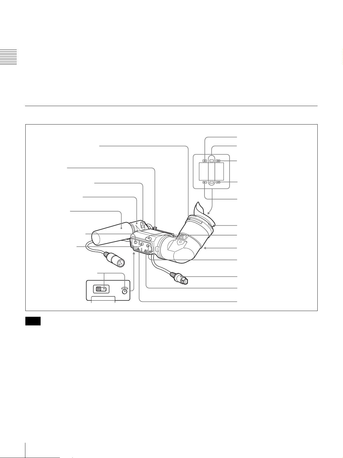
DXF-801 Viewfinder
1 Eyepiece focusing knob
2 Stopper
n MACRO (close-up) ring
For close-up, turn this ring while holding the MACRO
selector down.
6 TALLY indicator
7 REC/TALLY indicators
TALLY
BATTREC
8 BATT indicator
Microphone fixing screw
Microphone holder
Microphone
3 PEAKING control
4 CONTRAST
control
5 LIGHT switch and light
HIGH LOW OFF
LIGHT
Note
You can switch the scan size of the DXF-801 in
accordance with the aspect ratio selected on the camera or
camcorder. It operates in 4:3 mode when connected to the
DSR-400/400P. It operates in either 4:3 or 16:9 mode
when connected to the DSR-450WS/450WSP.
a Eyepiece focusing knob
Adjusts the viewfinder focus to match your eyesight (page
30).
b Stopper
Lift up when detaching the viewfinder (page 31).
SHUTTER GAIN UP
9 GAIN UP indicator
0 SHUTTER indicator
Eye cup
qa Tally lamp
qs Eyepiece release catch
qd BRIGHT control
qf Viewfinder connector
qg TALLY switch
qh DISPLAY switch
c PEAKING control
Adjusts the outline intensity of the viewfinder image (page
30).
d CONTRAST control
Adjusts the contrast of the viewfinder image (page 30).
e LIGHT switch and light
The light lights the lens and the switch controls the light as
follows.
HIGH: Brighter
LOW: Darker
OFF: Turns the light off.
20
Location and Function of Parts
Page 21
f TALLY (tally) indicator (green)
Flashes when the camcorder is in Interval Rec mode.
Flashing quickens while you are shooting in Interval Rec
mode.
For details on Interval Rec mode, see “Time-Lapse Video
(Interval Rec)” on page 63.
g REC/TALLY (recording/tally) indicators (red)
Functions as follows.
• Flashes from the time when you press the REC button on
the camcorder or the VTR button on the lens until
recording starts, then stay on continuously during
recording.
• Indicates a fault (page 125).
The lower indicator can also function by setting in the
(page 87).
menu
h BATT (battery) indicator (red)
Lights up when the battery capacity is low.
i GAIN UP indicator (orange)
Lights up when the gain is 3 dB or more.
Status display on the viewfinder
screen
The viewfinder screen displays not only the video picture
but also characters and messages indicating the camcorder
settings and operating status, a center marker, a safety zone
marker, etc.
When the MENU switch is set to OFF and the DISPLAY
switch is set to ON, the items for which an ON setting was
made in the VF DISP 1 page of the OPERATION menu or
with related switches are displayed at the top and bottom
of the screen.
The messages that give details of the settings and
adjustment progress and results can also be made to appear
for about 3 seconds while settings are being changed,
during adjustment, and after adjustment.
For details about the display item selection, see “Selecting
the display items” on page 98. For details about setting
change and adjustment progress messages, see “Display
modes and setting change confirmation/adjustment
progress messages” on page 99. For details about marker
display, see “Setting the marker display” on page 100.
Chapter 1 Overview
j SHUTTER indicator (red)
Lights up when the SHUTTER switch (page 10) is ON.
k Tally lamp
When the TALLY switch (see below) is in the ON
position, this operates in the same way as the REC/TALLY
indicators.
l Eyepiece release catch
To view the viewfinder screen directly, press to hinge up
the eyepiece.
m BRIGHT (brightness) control
Adjusts the brightness of the viewfinder image (page 30).
n Viewfinder connector (20-pin)
Connect to the VF connector (page 9).
o TALLY switch
Set to the ON position to use the tally lamp.
p DISPLAY switch
Set to OFF when you want to remove the character data
from the viewfinder and the monitor connected to the
MONITOR OUT connector
(page 14).
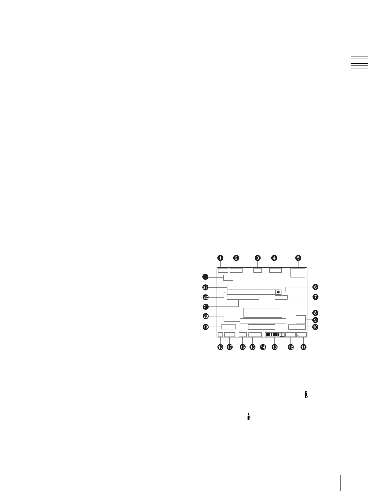
Layout of the status display on the
viewfinder screen
All items that can be displayed on the viewfinder screen
are shown below.
REC
PARA
24
6, 7, wa, ws, and wd appear only when color bars are displayed.
4: 3
DSR-400 #30001
05/ 03/23 01:43
SHOT ID(1 - 4)
D5600
1
W:A
a VTR operation indicators
VTR operation is displayed as follows:
REC1: The internal VTR is operating.
REC2: The external VTR connected to the (i.LINK)
DV OUT connecter is operating.
1
REC
: Both the internal VTR and the external VTR
2
connected to the
operating.
EX
3. 2K
WHITE NG
LEVEL TOO HIGH
TCG 00 : 00 : 00 : 00
LOW LIGHT
0dB
1/1000
16: 9
16. 0V
DC IN
DVCAM
15-10
EXT
IV
F5.6
(i.LINK) DV OUT connector are
Location and Function of Parts
21
Page 22
b Trigger mode
PARA: Operates both internal and external VTRs.
INT: Operates the internal VTR only.
EXT: Operates the external VTR only.
k Iris setting/auto iris override
Indicates the F value (iris setting) of the lens.
Also, the auto iris override is displayed using two squares
which appear in the upper and lower parts respectively.
c Extender
Chapter 1 Overview
“EX” is displayed when a lens extender is used.
d Color temperature
Indicates the currently selected color temperature.
e DC IN / battery voltage / remaining capacity
Indicates the battery voltage or the remaining capacity of
an attached internal battery pack, an AC adaptor, or an
external battery (a battery connected to the DC IN
connector).
When the power is supplied from an external battery, “DC
IN” appears here.
When the DISP BATT REMAIN item is set to INT on the
VF DISP 2 page of the OPERATION menu, the battery
voltage is not indicated.
However, when the Anton Bauer intelligent battery system
or the BP-GL65/GL95 battery pack is used, the remaining
battery capacity is automatically detected and indicated in
steps of 10%.
• Until the remaining battery capacity is reduced to 40%,
the indications MAX, 90%, 80%...40% are displayed for
three seconds in the viewfinder each time the remaining
battery capacity reduces by 10%.
• When the remaining battery capacity is less than 40%,
the indication is displayed all the time.
• When the remaining battery capacity is less than 10%*,
the indication flashes. When the remaining battery
capacity is reduced further, the “LOW” flashes.
* This value can be set to either 10% or 20% on the FUNCTION 2 page of
the OPERATION menu.
f * (Asterisk indicator)
Flashes when the color bars are displayed and is recorded
together with the color bars.
g 16:9 mode recording indicator (DSR-450WS/
450WSP only)
Indicates recording in the 16:9 mode. This indicator is
recorded together with the color bars.
h Setting change and adjustment progress message
display area
For details, see “Display modes and setting change
confirmation/adjustment progress messages” on page 99.
i EXT/IV indicator (DSR-450WS/450WSP only)
Displayed when a CBK-SC01 Composite Input Board is
installed for input of external composite signals.
j Recording format
Indicates the current recording format.
For details, see “Adjusting the iris” on page 55.
l Remaining tape capacity
Indicates the remaining tape recording time (in minutes) of
the VTR.
Examples of remaining tape recording time indication
Indication Remaining tape recording time
F - 30 Full to 30 minutes
30 - 25 30 to 25 minutes
25 - 20 25 to 20 minutes
20 - 15 20 to 15 minutes
15 - 10 15 to 10 minutes
10 - 5 10 to 5 minutes
5 - 0 5 to 0 minutes
No display 0 minute
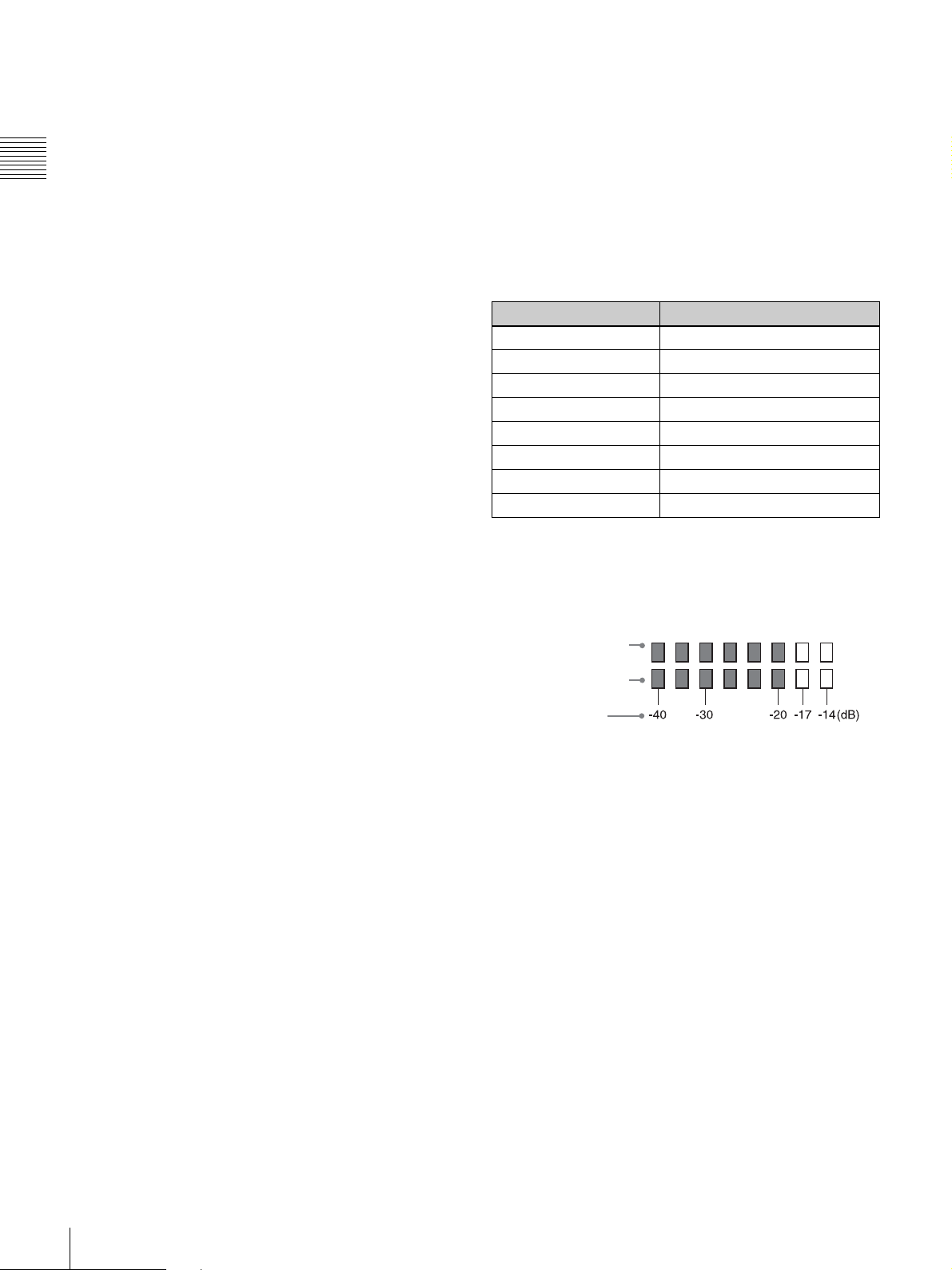
m Audio level
Indicates the level of audio channel 1 and channel 2. The
peak indication of the VTR level meter is related as
follows to the audio level when an 1kHz sine wave is input.
Audio channel 1 level
indicator
Audio channel 2 level
indicator
VTR level meter
indicator
n Operation/error message display area
For details, see “Operation/error messages” on page 127.
o Shutter speed
Indicates the shutter speed or the shutter mode. However,
if the SHUTTER switch
(page 10) is set to OFF, nothing is
displayed.
1/100, 1/125, 1/250, 1/500, 1/1000, 1/2000: Shutter speed
(in seconds) in standard mode (scan mode: I)
1/40, 1/60, 1/120, 1/125, 1/250, 1/500, 1/1000, 1/2000:
Shutter speed (in seconds) in standard mode (scan
mode: PsF)
ECS: In ECS (Extended Clear Scan) mode
EVS: In EVS (Super Enhanced Vertical Definition
System) mode
1F to 8F, 16F (DSR-450WS/450WSP only): Number of
frames in the slow speed shutter mode
p Gain
Indicates the gain of the video amplifier, as set by the
GAIN switch.
22
Location and Function of Parts
Page 23
q White balance memory
Indicates the currently selected white balance automatic
adjustment memory.
A: Displayed when the WHITE BAL switch is set to A.
B: Displayed when the WHITE BAL switch is set to B.
P: Displayed when the WHITE BAL switch is set to PRST
or when the preset button on an RM-B150 has been
pushed.
T: Displayed when ATW is being used.
r Filter
Indicates the currently selected filter types.
s 5600 indicator
Appears when the electric color temperature filter function
is on.
t Time code
Indicates the elapsed recording/playback time, the time
code, user bits or other information selected by the
DISPLAY switch
(page 21).
u ID number
Indicates the ID number selected from ID 1 to ID 4 when
the color bars are displayed. The ID number is recorded
together with the color bars.
v Date and time
Indicates the date and time of recording when the color
bars are displayed, which are recorded together with the
color bars.
w Model name and serial number
Indicates the model name and serial number of the
camcorder when the color bars are displayed, which are
recorded together with the color bars.
x 16:9/4:3 mode
“16:9” or “4:3” is displayed depending on the currently
selected aspect ratio.
Note
Status display on the LCD monitor
The following display appears when the LCD monitor
display is set to STATUS with the DISP SEL button.
Chapter 1 Overview
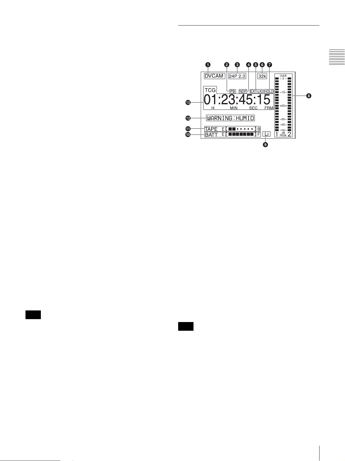
a Video format
Indicates the video format of the image that is currently
playing or being recorded.
DVCAM: The video format is set to DVCAM mode.
DV-SP: The video format is set to DV-SP mode.
b Playback indicator
Appears during playback.
c Camera scan mode indicator
Indicates the camera scan mode of the image that is
currently playing back or being recorded.
• For DSR-400/450WS only
60i: 60 fields per second, interlace scan mode
30P: 30 frames per second, progressive scan mode
24P 2.3: 24 frames per second, progressive scan mode
(converted to 60i at 2-3 pulldown)
24P 2.3.3.2: 24 frame per second, progressive scan
mode (converted to 60i at 2-3-3-2 pulldown)
• For DSR-400P/450WSP only
50i: 50 fields per second, interlace scan mode
25P: 25 frames per second, progressive scan mode
The 16:9 mode can be selected for the DSR-450WS/
450WSP.
Note
There may be no indication displayed when this unit
cannot identify the camera scan mode, for example, when
playing back a tape recorded with other equipment.
d Non drop-frame mode indicator (DSR-400/450WS
only)
Appears when non-drop frame mode is selected.
e External synchronization indicator
Appears when the internal time code generator is locked to
an external signal input to the TC IN connector.
Location and Function of Parts
23
Page 24
f Audio format
Indicates the audio format of image that is currently
playing or being recorded.
32k: 12 bit Fs32K (4ch mode)
44.1k: 16 bit Fs44.1K (2ch mode)
48k: 16 bit Fs48K (2ch mode)
Chapter 1 Overview
g Hold indicator
Appears when the internal time code generator is stopped.
h Audio level indicators
Indicates the audio recording or playback levels of channel
1 and channel 2.
Note
i Lithium backup battery warning
Appears when the voltage of the internal lithium backup
Recording in 16 bit Fs32K and 16 bit Fs44.1K are not
possible on the camcorder.
battery (CR2032) is low. If this indication appears, replace
the lithium backup battery immediately
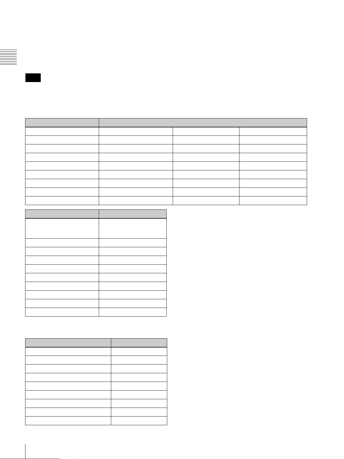
j Battery capacity indicator
Indication Battery voltage
BP-L60S/L90A/L60A/L90/L60 BP-90A/NP-1B Other batteries
BATT E [ ■■■■■■■ ] F 15.5V or more 12.0V or more 17.0V or more
BATT E [ ■■■■■■ ] F 15.1 to 15.5V 11.7 to 12.0V 16.0 to 17.0V
BATT E [ ■■■■■ ] F 14.6 to 15.1V 11.5 to 11.7V 15.0 to 16.0V
BATT E [ ■■■■ ] F 13.8 to 14.6V 11.3 to 11.5V 14.0 to 15.0V
BATT E [ ■■■ ] F 12.9 to 13.8V 11.1 to 11.3V 13.0 to 14.0V
BATT E [ ■■ ] F 12.0 to 12.9V 10.9 to 11.1V 12.0 to 13.0V
BATT E [ ■ ] F 10.8 to 12.0V 10.5 to 10.9V 11.0V to 12.0V
BATT E [ ] F 10.8V or less 10.5V or less 11.0V or less
Indication Battery voltage
BP-IL75/GL65/GL95/
M100/M50, Anton Bauer
Battery System
BATT E [ ■■■■■■■ ] F 80 to 100%
BATT E [ ■■■■■■■ ] 70%
BATT E [ ■■■■■■ ] 60%
BATT E [ ■■■■■ ] 50%
BATT E [ ■■■■ ] 40%
BATT E [ ■■■ ] 30%
BATT E [ ■■ ] 20%
BATT E [ ■ ] 10%
BATT E [ ] 0%
(page 29).
k Tape remaining indicator
Indication Tape time remaining
TAP E E [ ■■■■■■■ ] B 30 minutes
TAP E E [ ■■■■■■ ] B 25 to 30 minutes
TAP E E [ ■■■■■ ] B 20 to 25 minutes
TAP E E [ ■■■■ ] B 15 to 20 minutes
TAP E E [ ■■■ ] B 10 to 15 minutes
TAP E E [ ■■ ] B 5 to 10 minutes
TAP E E [ ■ ] B 2 to 5 minutes
TAP E E [ ■ ] B (flashing) 0 to 2 minutes
TAP E E [ ] B (flashing) 0
24
Location and Function of Parts
Page 25

l Warning indicators
Displays warnings when trouble with recording or
moisture condensation occurs.
For details, see “Operation Warnings” on page 125.
m Time counter indicator
Each press of the DISPLAY button switches displays of
time code, user bit, and counter. You can display the date
or time using the arrow key under the AUDIO adjustment
cover.
TCG: Value of time code generator
TCR: Value of time code reader
UBG: Value of user bit generator
UBR: Value of user bit reader
CNT: Counter indicator
CLK: Current time data
DAT: Current date
TCG and UBG can be displayed when the tape is stopped
and during recording, and TCR and UBR are displayed
during playback.
CLK can be displayed when the center of the arrow key is
pressed while TC is being displayed by pressing the
DISPLAY button.
Using the CD-ROM
Manual
Chapter 1 Overview
The supplied CD-ROM includes versions of the Operating
Instructions for the DSR-400/400P/450WS/450WSP in
English, French, German, Italian, and Spanish.
CD-ROM system requirements
The following are required to access the supplied CDROM disc.
• Computer: PC with Intel Pentium CPU
- Installed memory: 64 MB or more
- CD-ROM drive: ×8 or faster
• Monitor: Monitor supporting resolution of 800 × 600 or
higher
• Operating system: Microsoft Windows Millennium
Edition, Windows 2000 Service Pack 2, Windows XP
Professional or Windows XP Home Edition
When these requirements are not met, access to the CDROM disc may be slow, or not possible at all.
DAT can be displayed when the center of the arrow key is
pressed while U-BIT is being displayed by pressing the
DISPLAY button.
Preparations
One of the following programs must be installed on your
computer in order to use the operation manuals contained
on the CD-ROM disc.
• Adobe Acrobat Reader Version 4.0 or higher
• Adobe Reader Version 6.0 or higher
Note
If Adobe Reader is not installed, you can download it from
the following URL:
http://www.adobe.com/
Reading the CD-ROM manual
To read the operation manual contained on the CD-ROM
disc, do the following.
1
Insert the CD-ROM disc in your CD-ROM drive.
A cover page appears automatically in your browser. If
it does not appear automatically in the browser,
double-click the index.htm file on the CD-ROM disc.
2
Select and click the operation manual that you want to
read.
This opens the PDF file of the operation manual.
Using the CD-ROM Manual
25
Page 26

Note
If you lose the CD-ROM disc or become unable to read its
content, for example because of a hardware failure, you
can purchase a new CD-ROM disc to replace one that has
been lost or damaged. Contact your Sony service
Chapter 1 Overview
representative.
• Intel and Pentium are registered trademarks of Intel
Corporation or its subsidiaries in the United States and
other countries.
• Microsoft and Windows are registered trademarks of
Microsoft Corporation in the United States and/or other
countries.
• Adobe, Acrobat, and Adobe Reader are trademarks of
Adobe Systems Incorporated in the United States and/
or other countries.
26
Using the CD-ROM Manual
Page 27
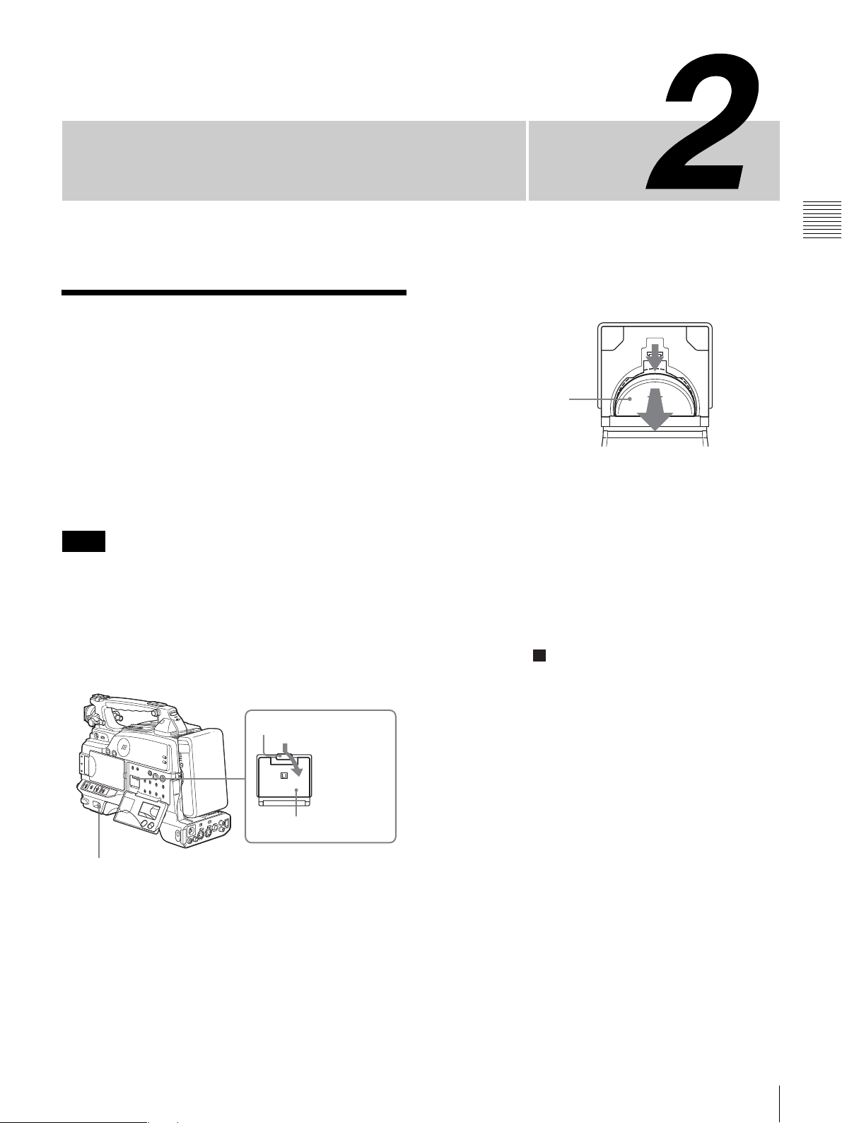
Preparation
Attaching and Replacing
the Lithium Battery
Chapter
3
Take out the lithium battery.
Chapter 2 Preparation
This camcorder uses a lithium battery to retain stored data.
When using the camcorder for the first time, be sure to
attach the supplied lithium battery (CR2032). The
camcorder will not operate correctly without this lithium
battery. After attaching the lithium battery, set the date and
time of the internal clock (see
internal clock” on page 105).
Notes
• Carefully read the instructions for attaching and
replacing the lithium battery. Lithium batteries can
explode if misused.
• Use only CR2032 Lithium Batteries. Other types of
lithium batteries may come loose when this camcorder is
moved. If you have difficulty finding CR2032 Lithium
Batteries, contact your Sony dealer.
“Setting the date/time of the
Catch
LITHIUM BATT
2
Press and pull
forward.
Press down and pull out
toward you.
4
Reverse step 3 to insert a replacement lithium battery.
Make sure that the + symbol on the battery is facing
you.
5
Close the battery cover.
Service life of the lithium battery
When the lithium battery’s voltage falls, the lithium
battery power replacement warning appears on the LCD
monitor
lithium battery ( CR2032) within three or four days.
The lithium battery has an average service life of about one
year.
(page 24). If this warning appears, replace the
Li
Battery cover
1
1
Set the POWER switch to on.
2
Press down the catch at the top of the battery cover and
open the cover.
Attaching and Replacing the Lithium Battery
27
Page 28
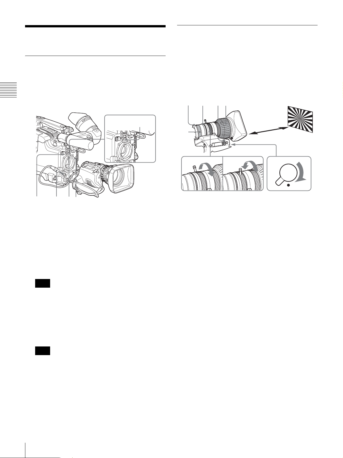
Preparing the Lens
Mounting the lens
Mount the lens using the following procedure.
For information about using the lens, refer to the
operating instructions for the lens.
Chapter 2 Preparation
3
Lens mount
securing rubber
Adjusting the flange focal length
It is necessary to adjust the flange focal length (the
distance from the lens flange to the plane of the image
along the optical axis) in the following cases.
• When a lens is fitted for the first time
• After changing lenses
• When during zoom operations the focus does not match
properly from telephoto to wide angle
1
4,11
2
7
3
1
245
1
Push the lens locking lever up and remove the lens
mount cap from the lens mount.
2
Align the center slot in the lens mount with the center
pin on the lens, and insert the lens into the mount.
3
Holding the lens in place, push the lens locking lever
down to mount the lens.
Note
If the lens is not firmly locked, it may come off while
the camcorder is being used. This could cause a serious
accident. Make sure the lens is firmly locked. It is
recommended that the lens mount securing rubber be
put on the lens-locking lever as illustrated above.
9
8
1
Set the iris selector to the M (Manual) position.
2
Turn the iris ring to open it.
Adjust the light or the ND filter so that an appropriate
brightness is obtained with the iris open.
3
Place the supplied flange focal length adjustment test
chart at a range of about 3 meters (10 feet), and adjust
the light so that an appropriate video level is obtained
with the iris open.
4
Loosen the F.f fixing knob.
5
Set the ZOOM selector to the M position.
6
Turn the zoom ring to the telephoto position.
7
Turn the focus ring so that the test chart is in focus.
A
T
M
IR
W
R
ET
6
IS
5
ZOOM
S
M
4
5
28
Connect the lens cable to the LENS connector.
Note
Connecting the lens cable to the LENS connector
when the camcorder is powered may cause a
malfunction of the camcorder or the lens. Turn off the
camcorder before connecting the LENS connector.
Secure the lens cable with the cable clamps.
Preparing the Lens
8
Turn the zoom ring to the wide angle position.
9
Turn the F.f fixing ring so that the test chart is in focus.
Do not move the focusing ring.
10
Repeat steps 6 to 9 until the image stays in focus from
telephoto to wide angle.
11
After adjustment, tighten the screw of the F.f fixing
knob.
Page 29
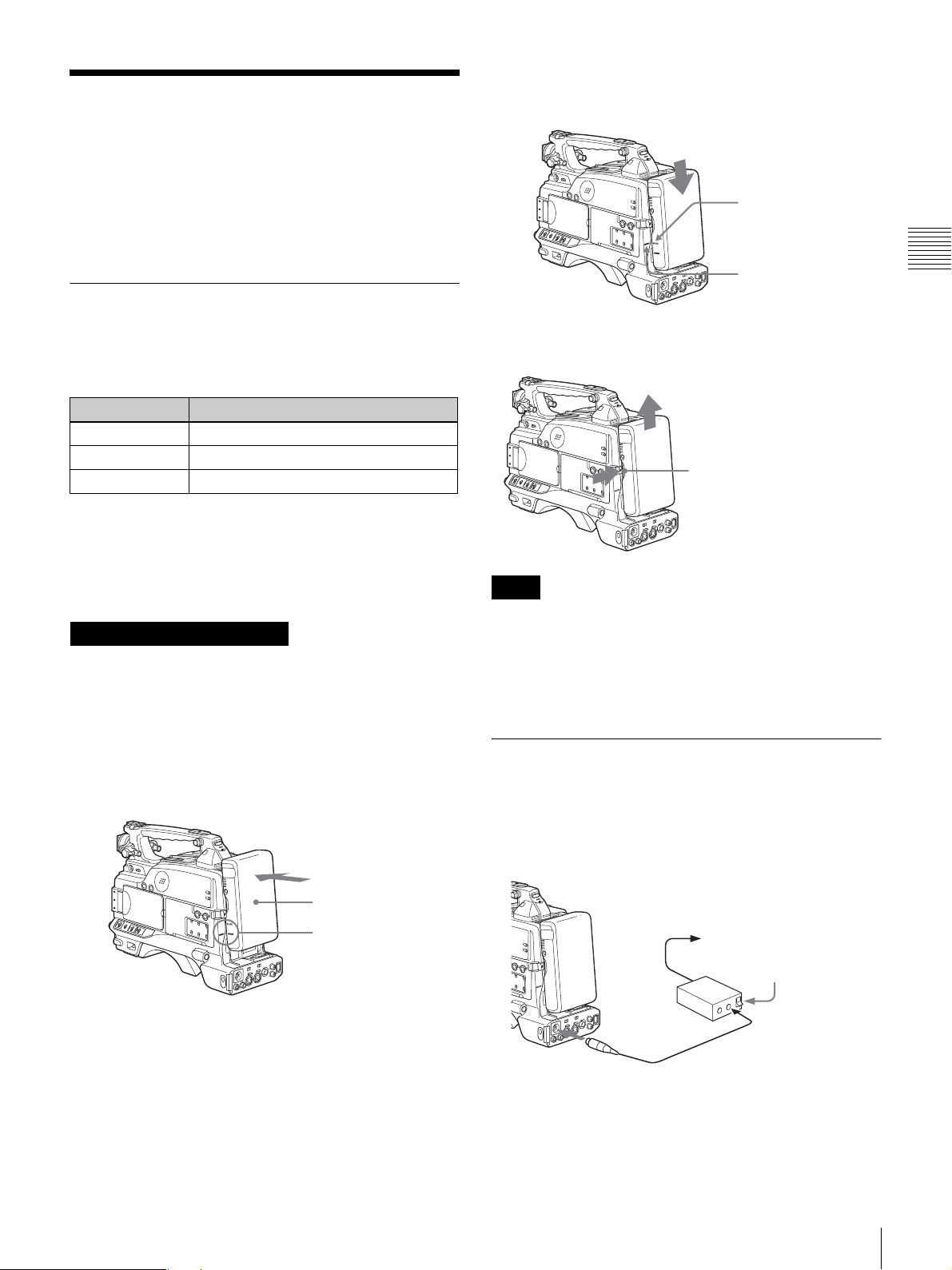
Preparing a Power Supply
The following power supplies are recommended for the
camcorder.
• BP-GL65/GL95/L60S Lithium-ion Battery Pack
• AC power using the AC-550, AC-DN2, AC-DN10 AC
adaptor
2
Slide the battery pack down until its “LOCK” arrow
points at the matching line on the camcorder.
“LOCK” arrow
Using a battery pack
When a BP-GL65/GL95/L60S Battery Pack is used, the
camcorder will operate continuously for the time shown
below.
Model name Operating time
BP-GL65 Approx. 180 minutes
BP-GL95 Approx. 300 minutes
BP-L60S Approx. 170 minutes
Before use, charge the battery pack with a charger suitable
for each battery.
For details on charging procedure, refer to the battery
charger operation manual.
Note on using the battery pack
A warm battery pack may not be able to be fully recharged.
To attach the battery pack
Line on the camcorder
To detach the battery pack
Holding the button in, pull
the battery pack up.
Notes
• During recording, playback, and loading/unloading a
tape, be careful never to remove the battery pack.
• Make sure to turn the camcorder off before changing the
battery (except when using an AC-550 and an AC-DN2/
DN10 AC adaptor together).
Chapter 2 Preparation
1
Press the battery pack against the back of the
camcorder, aligning the line on the side of the battery
pack with the matching line on the camcorder.
BP-GL65/GL95/L60S
Align these lines.
Back of the camcorder
Using an AC adaptor
To use the AC-550 AC adaptor
Connect the camcorder to the AC power supply through an
AC-550 AC Adaptor as shown in the following figure, and
turn the POWER switch of the AC-550 on.
to an AC power source
Power switch on
AC Adaptor
AC-550
DC IN
DC output cable (supplied with the AC-550)
DC OUT
Preparing a Power Supply
29
Page 30
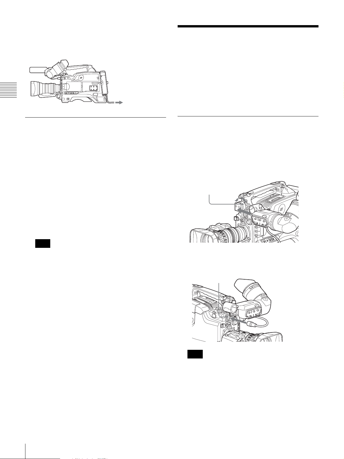
To use the AC-DN10 AC adaptor
Mount an AC-DN10 on the camcorder in the same way as
a battery pack, then connect to the AC power supply.
The AC-DN10 can supply up to 100 W of power.
Chapter 2 Preparation
to an AC power source
Adjusting the Viewfinder
Depending on the eyesight of the operator — whether
longsighted or shortsighted — the optimal position of the
viewfinder image varies. Adjusting brightness, contrast,
and so on, improves the visibility of the viewfinder screen.
Although these adjustments may make the viewfinder
image clearer, they have no effect on the output video
signal from the camcorder.
Avoiding breaks in operation due to
an exhausted battery
When the battery pack is becoming exhausted, you can
perform battery replacement without causing a break to the
camcorder operation by using an AC adaptor.
1
Turn the AC-550 AC adaptor on.
2
Connect an AC-550 AC Adaptor to an AC power
source, then connect it to the DC IN connector of the
camcorder
The power source switches automatically from the
battery pack to the AC adaptor connected to the DC IN
connector.
Note
There may be some noise on the video signal at the
time of power source switching.
3
Replace the battery pack with a fully charged one.
(page 29).
Fitting the viewfinder
Remove any microphone from the viewfinder beforehand.
1
Slide the viewfinder into the holder on the camera,
then tighten the viewfinder left-to-light position fixing
ring.
Viewfinder left-to-right
position fixing ring
2
Connect the viewfinder connector to the VF
connector.
VF connector
30
Adjusting the Viewfinder
Note
Push the connector all the way into the VF connector.
To remove the viewfinder
Reverse the fitting procedure. Please note that you should
slide the viewfinder out while pulling the viewfinder
stopper up.
Page 31
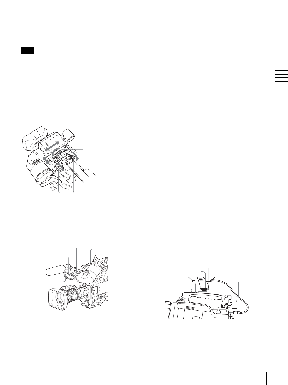
To use the camcorder with your left eye
By fitting a left eye adaptor to the DXF-801, you can use
the camcorder with your left eye to the viewfinder.
Note
You cannot stow the camcorder in the carrying case with
the left-eye adaptor attached.
For details, consult your Sony dealer.
Adjusting the viewfinder position
To adjust the viewfinder left-to-right position, loosen the
left-to-right fixing ring, and to adjust the front-to-back
position, loosen the front-to-back position locking knob.
Viewfinder left-to-right position
fixing ring
image for your eyesight. The adjustment range is from –3
to 0 diopters.
Using an optional part of the DXF-801 allows you to
modify the adjustment range to –2 to +1 diopters or – 0.5
to +3 diopters.
For details, consult your Sony dealer.
To adjust contrast and brightness
Carry out these adjustments with the color bars displayed.
1
Set the OUTPUT/DCC switch to the BARS position.
The color bars appear in the viewfinder.
2
Watching the color bars, turn the CONTRAST and
BRIGHT controls to adjust the contrast and
brightness.
3
Return the OUTPUT/DCC switch to its original
position.
To adjust the outline emphasis
Turning the PEAKING control changes the degree of
outline emphasis in the viewfinder image, to make
focusing easier.
Chapter 2 Preparation
Viewfinder front-to-back
position locking knob
Adjusting the eyepiece focus and
the screen (brightness, contrast,
and outline emphasis)
BRIGHT control
CONTRAST control
PEAKING control
Eyepiece focusing
knob
OUTPUT/DCC switch
Attaching a 5-inch electronic
viewfinder
You can attach an optional DXF-51 (5-inch) Electronic
Viewfinder. To attach it, an Accessory Shoe Kit (part
number A-8274-968-B) is required.
For details, contact your Sony dealer.
Remove the cover of the grip and attach the shoe and
stopper screw (of the Accessory Shoe Kit).
Guide
Fixing ring
VF Cable
Shoe*
Stopper screw*
* Supplied with the Accessory Shoe Kit
To adjust the eyepiece focus
First focus the image with the lens, then adjust the
eyepiece focusing knob to get the clearest viewfinder
Adjusting the Viewfinder
31
Page 32
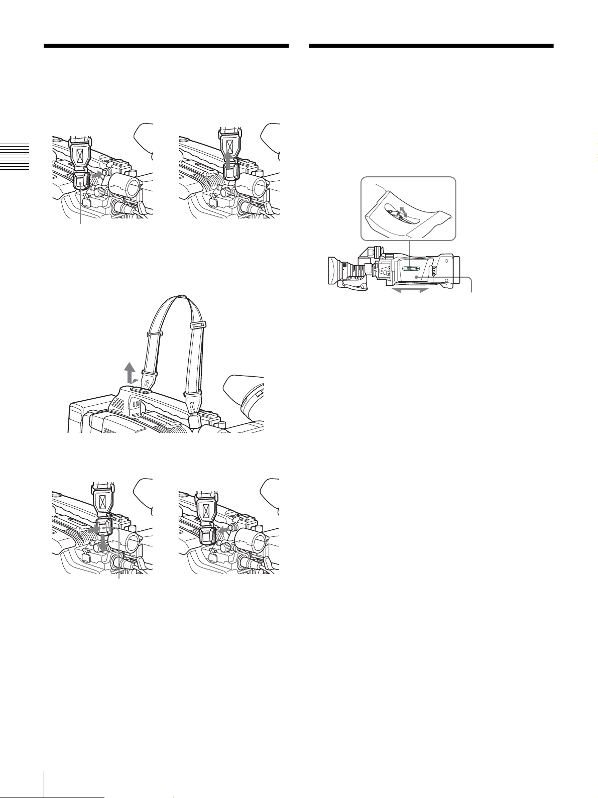
Using the Shoulder Strap
1
Fit one of the clips to a shoulder strap fitting.
Chapter 2 Preparation
g
Adjusting the Shoulder
Pad Position
You can shift the shoulder pad backward or forward by up
to 3 5 mm (1
best balance for shooting with the camcorder on your
shoulder.
7/16 inches). This adjustment helps you get the
1,3
Clip
2
Fit the other clip to the shoulder strap fitting on the
other side of the grip in the same way.
To remove the shoulder strap
Pull up the strap to lock
the fitting.
Bottom of the
camcorder
2
1
Raise the lever in the center of the shoulder pad to
unlock the shoulder pad.
2
Slide the shoulder pad backward or forward until it is
in the most convenient position.
3
Bring down the lever to lock the shoulder pad in the
selected position.
Shoulder pad
32
Using the Shoulder Strap
g
Pull in the direction of the arrow
while pressing here.
Page 33
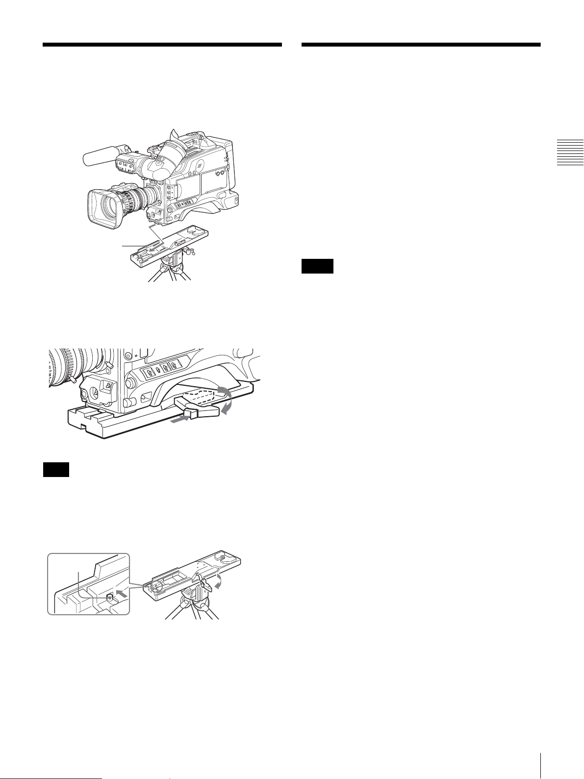
Fitting to a Tripod
Using a Video Light
First fit the VCT-U14 Tripod Adaptor to the tripod, then
mount the camcorder on the tripod adaptor.
VCT-U14 Tripod
Adaptor
Slide the camcorder forward along the slot, until it
clicks firmly into place.
Tripod
To remove a tripod
You can use the Anton Bauer Ultralight 2 or equivalent for
this camcorder. Use a video light powered by 12 V with
maximum power consumption of 50 W.
• If you connect the video light to the LIGHT connector on
the camcorder and set the LIGHT switch to AUTO, you
can turn the light on and off automatically as you start
and stop the VTR operation.
• The output of the video light connector on the camcorder
is controlled to 12 V even when the camcorder is
supplied with 12 V or more power (through the DC IN
connector or battery pack). The brightness or color
temperature of the light will not change according to
voltage increase.
Notes
• Do not use a video light with power consumption of over
50 W.
• The brightness or color temperature of the light will
change when the supplied voltage (through the DC IN
connector or battery pack) is under 12 V.
To attach the video light
Fit the video light to the camcorder grip or the accessory
shoe and connect the video light cable to the LIGHT
connector.
Chapter 2 Preparation
Hold down the red button and pull the
lever in the direction of the arrow.
Note
After removing the camcorder, if the tripod adaptor pin has
not returned to its original position, hold down the red
button and move the lever in the direction of the arrow to
return the pin to its original position. It is not possible to
mount a camcorder with the pin left out.
Pin
Fitting to a Tripod
33
Page 34
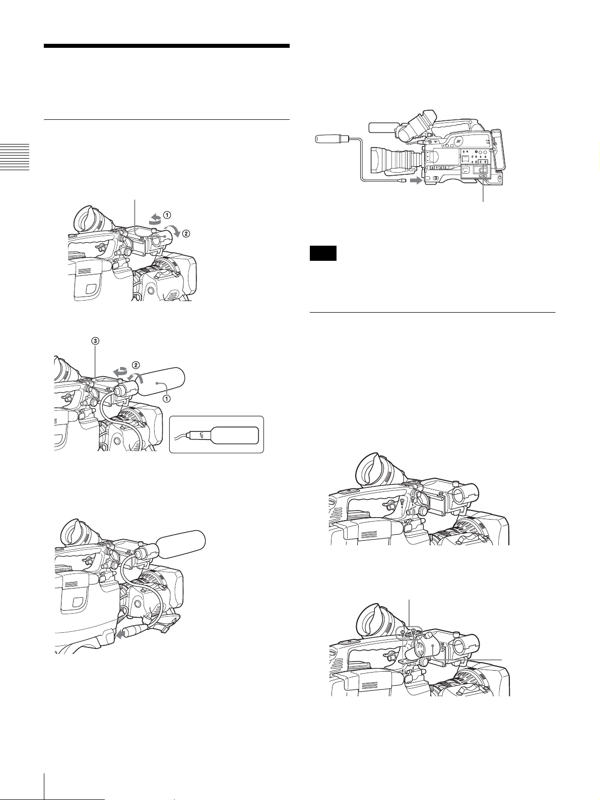
Preparing Audio Input
S
System
Using the supplied microphone
1
Loosen the screw and open the microphone holder
Chapter 2 Preparation
clamp.
To use the microphone detached from the
camcorder
You can use the supplied microphone detached from the
camcorder.
Clamp of the microphone holder
2
Place the microphone in the microphone holder.
Tighten the screw.
Close the microphone holder.
Place the microphone in the
holder so that “UP” is at the top.
3
Plug the microphone cable into the MIC IN connector,
then set the AUDIO IN (CH-1/CH-2) switch for the
desired recording channel to FRONT.
Connect to the MIC IN
connector.
Note
When using the supplied microphone with an extension
cable, always use an external power supply type cable.
Set the AUDIO IN (CH-1/CH-2)
switch for the desired audio
recording channel to FRONT.
Using an external microphone
You can connect up to two external monaural microphones
to the AUDIO IN CH-1/CH-2 connectors, using a CAC-12
Microphone Holder (not supplied).
The procedure below is an example showing attachment of
an ECM-670/672/etc. Electret Condenser Microphone.
1
Remove the fixing screws for external microphone
holder.
34
Preparing Audio Input System
Connect to the MIC IN connector.
2
Attach the CAC-12 Microphone Holder.
crews removed in step 1
3
Open the CAC-12 and remove the microphone
adaptor.
CAC-12
Page 35
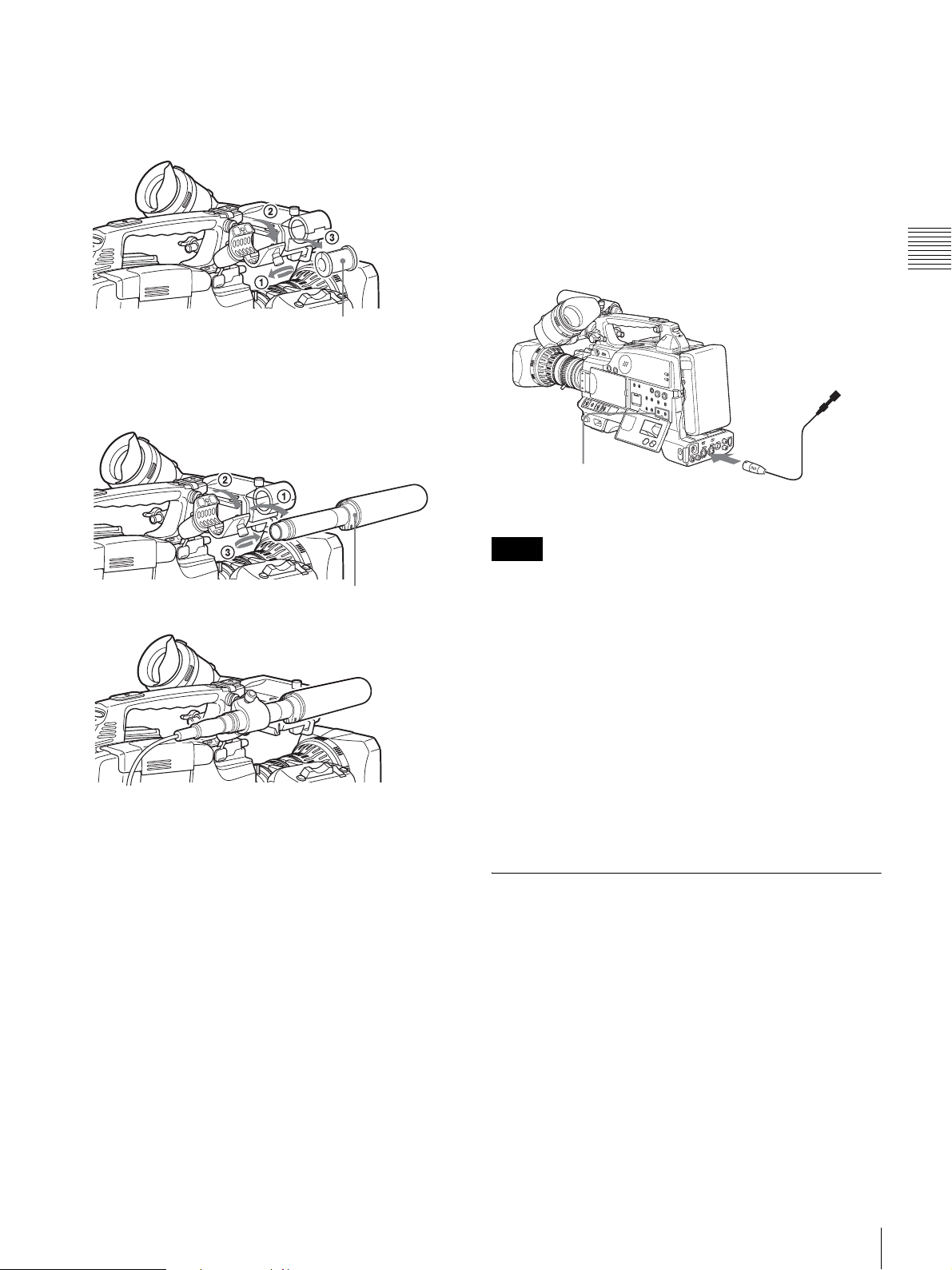
Use the microphone adaptor when using a smalldiameter external microphone. When attaching an
ECM-670, use the microphone adaptor supplied with
these microphone.
Open the CAC-12.
6
Set the switches as follows.
• Set the AUDIO IN input selection switch as
indicated below, depending on the type of
microphone used.
- When using a microphone with an internal power
supply, set it to MIC (center).
- When using a microphone with an external power
supply, set it to MIC +48V ON (right).
• Set the AUDIO IN (CH-1/CH-2) switch of the
channel that the microphone is connected to REAR.
Chapter 2 Preparation
Loosen the screw.
4
Place an external microphone (ECM-670/672/etc.
Microphone adaptor
Electret Condenser Microphone or similar
microphone) in the CAC-12.
Close the CAC-12.
m
Tighten the screw.
5
Connect the microphone cable to the AUDIO IN CH-
ECM-670/672 or
similar microphone
1 or CH-2 connector.
Monaural microphone
AUDIO IN (CH-1/CH-2)
switches
Notes
to AUDIO IN CH-1/CH-2
connector
• The camcorder can use a microphone with an input level
of – 60 dB. Other microphones may not be suitable for
use with this camcorder due to differences in the input
level.
• In order for the AUDIO IN CH-1 and CH-2 connectors
on the camcorder to be able to provide a phantom 48 V
power supply, female XLR connectors (3-pin) are fitted.
If the microphone cable has a female connector, use an
adaptor.
• When you detach a CAC-12 Microphone Holder once
you have attached to the camcorder, be careful not to
lose the two screws fixing the CAC-12. After detaching
the CAC-12, be sure to put the two screws back into their
original places.
Using a wireless microphone
system
You can use the wireless microphone system including
following models to record sound.
• UHF Wireless Microphone
NTSC system: WRT-807B, WRT-847B
PAL system: WRT-807A/B, WRT-847A/B
• UHF Synthesized Transmitter
NTSC system: WRT-8B, WRT-822B
PAL system: WRT-8B, WRT-822A/B
• UHF Synthesizer Tuner
NTSC system: WRR-855B, WRR-861B, WRR-862B
PAL system: WRR-855A/B, WRR-861A/B (in
Australia and Asia only), WRR-862A/B
Preparing Audio Input System
35
Page 36
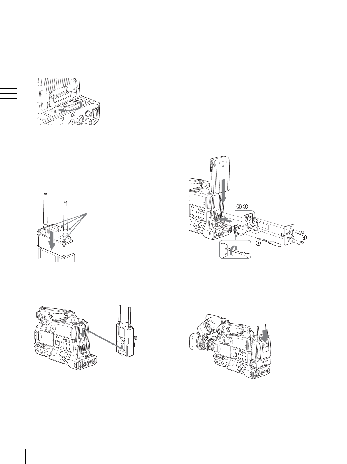
For details on using the wireless microphone system, see
the operating instructions for the microphone and tuner.
To attach a WRR-855
1
Open the cover of the WRR connector.
WRR connector
Chapter 2 Preparation
To attach a WRR-861/862 (When using a
BP-GL65/GL95/L60S Battery Pack)
1
Attach a WRR tuner fitting (not supplied, service part
number A-8278-057-A) to the back of the camcorder.
1 Use a Phillips type screwdriver to tighten the four
screws placed in the tuner fitting as illustrated
below.
2 Loosen the adjustment screws of the tuner fitting.
3 Adjust the tuner fitting position for a BP-GL65/
GL95/L60S Battery Pack to be attached, and
tighten the adjustment screws to fix its position.
2
Turn on a WRR-855, and set the MUTING to ON or
OFF.
The power of a WRR-855 can be synchronized with
the POWER switch of the camcorder.
3
Insert the WRR-855 into the CA-WR855.
Fasten the screws (supplied with
the WRR-855).
4
Fit the attachment plate on the rear side of the CAWR855 to the V-groove on the battery attachment
interface, and then slide the CA-WR855 down until it
connects to the WRR connector.
4 Attach the mount plate supplied with the WRR-
861/862.
BP-GL65/GL95/L60S
Adjustment
screws
Back of the
camcorder
2
Attach the battery pack.
For details about attaching the battery pack, see
“Using a battery pack” on page 29.
3
Mount the tuner on the WRR tuner fitting.
Mount plate (supplied
with WRR-861/862)
Phillips type screwdriver
5
Set one of the AUDIO IN (CH-1/CH-2) switches to
WRR (wireless).
36
Preparing Audio Input System
WRR-861/862
CA-WR855
For details about the WRR tuner fitting (part number
A-8278-057-A), contact your Sony service
representatives.
Page 37
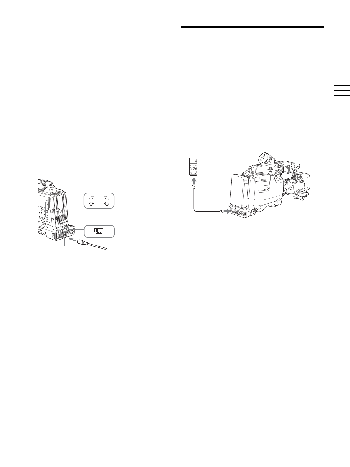
4
Connect the tuner power cord to the DC OUT
connector of the camcorder, and the audio output cable
to the AUDIO IN CH-1 or CH-2 connector.
5
Set the switches as below.
• Set the AUDIO IN input selection switch to MIC for
the channel to which the audio out cable is
connected.
• Set the AUDIO IN (CH-1/CH-2) switch for the
channel to which the audio output cable is connected
to REAR.
Connecting line input audio
equipment
Connecting the Remote
Control Unit
(DSR-450WS/450WSP
only)
Connecting the RM-B150/B750 Remote Control Unit
enables remote control of the principal camera and VTR
functions.
Connecting the remote control unit to the REMOTE
connector (8-pin) automatically puts the camcorder into
remote control mode. If you disconnect the remote control
unit, the remote control mode is cancelled.
Chapter 2 Preparation
1
Connect an audio mixer or other external audio system
component to the AUDIO IN CH-1/CH-2 connector as
shown below.
AUDIO IN (CH-1/CH-2) switches:
Set to REAR.
AUDIO IN
FRONT
WRR
REAR
AUDIO IN input selection switch:
Set to LINE.
+48V ON
LINE MIC
AUDIO IN CH-1/CH-2
connectors
2
Set the AUDIO IN input selection switch to LINE for
the channel to which the external audio equipment is
connected.
Selection of the recording audio input
Set the AUDIO IN (CH-1/CH-2) switch to REAR for the
channel to which the external audio equipment is
connected.
If you record and adjust both channel 1 and 2, set both
AUDIO IN (CH-1/CH-2) switches to REAR.
To audio mixer, etc.
RM-B150/B750
Remote
connector
Remote control cable
Camcorder switch functions when the
remote control unit is connected
The following switches on the camcorder do not function.
• GAIN switch
• OUTPUT/DCC switch
• WHITE BAL switch
• AUTO W/B BAL switch
• SHUTTER switch
• REC button (the VTR button on the lens and the
ASSIGN switch to which the REC SWITCH function is
assigned) when the RM REC START item is set to RM
on the FUNCTION 3 page of the MAINTENANCE
menu.
For details of the function of the REC button, see
“Function of the REC button when the remote control unit
is connected” on page 38.
Paint adjustment when the remote control
unit is connected
The settings of the paint adjustment that were in effect the
last time the remote control unit was used are recalled.
Connecting the Remote Control Unit (DSR-450WS/450WSP only)
37
Page 38
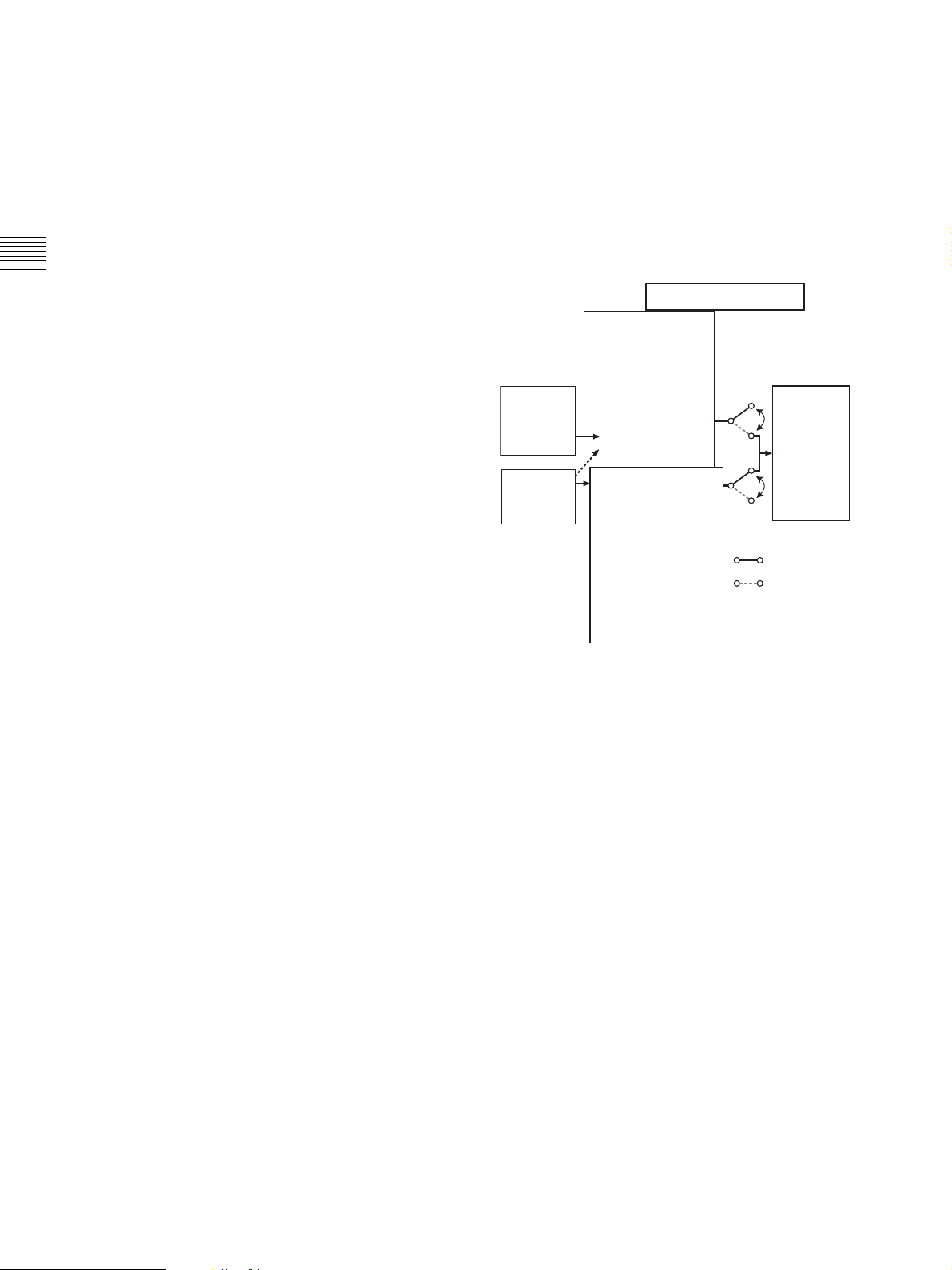
Function of the REC button when the
remote control unit is connected
You can select the function of the REC button on the
camcorder when the remote control unit is connected,
using the RM REC START item on the FUNCTION 3
page of the MAINTENANCE menu.
To disable the camcorder REC button and the
lens VTR button
On the FUNCTION 3 page of the MAINTENANCE
Chapter 2 Preparation
menu, set RM REC START to RM.
If the REC SWITCH function is assigned to the ASSIGN
switch, this setting also disables these controls.
To enable the camcorder REC button and the lens
VTR button
On the FUNCTION 3 page of the MAINTENANCE
menu, set RM REC START to CAM.
If the REC SWITCH function is assigned to the ASSIGN
switch, this setting also enables these controls. In this case,
the VTR button on the remote control unit is disabled.
To enable all of the camcorder REC button, the
lens VTR button, and the remote control unit VTR
button
On the FUNCTION 3 page of the MAINTENANCE
menu, set RM REC START to PARA.
If the REC SWITCH function is assigned to the ASSIGN
switch, this setting also enables these controls.
Structure of the paint adjustment data
The non-volatile memory of the camcorder used for
storing paint adjustment data consists of two regions as
shown below: one is the “independent data region” that is
used when a remote control unit is not connected, and the
other is the “remote control data region” that is used when
a remote control unit is connected. Paint adjustment data is
automatically selected and output to the camcorder
depending on whether or not a remote control unit, such as
an RM-B150, is connected.
Non-volatile memory
Independent data
region
MASTER BLACK
Setup
menu of the
camcorder
RM-B150
MASTER GAMMA
KNEE POINT
DETAIL LEVEL
R/B GAIN
R/B BLACK
Remote control
data region
MASTER BLACK
MASTER GAMMA
KNEE POINT
DETAIL LEVEL
R/B GAIN
R/B BLACK
Hardware
of the
camera
RM-B150 connected
RM-B150 not
connected
When the monitor is connected to the
remote control unit
The MONITOR connector (BNC type) of the RM-B150/
B750 outputs the same signal as that from the MONITOR
OUT connector on the camcorder.
Use the black cable supplied with the RM-B150/B750 to
connect the monitor to the MONITOR connector on the
RM-B150/B750.
When the remote control unit is
disconnected from the camcorder
The camcorder settings return to the settings in effect
before the remote control unit was connected.
By making a menu setting, the setting of the paint
adjustment made with the remote control unit can be
retained even after the remote control unit is removed from
the camcorder.
For details, see “To use settings of the paint adjustment
data stored in the “independent data region” even when a
remote control unit is connected” on page 39.
Thus, when a remote control unit is connected to the
camcorder, the effective data region is switched to the
“remote control data region” and the settings of the paint
adjustment that were in effect last time the remote control
unit was used are recalled.
Settings of the absolute value volume 1) and absolute value
switches
2)
are overwritten by those on the remote control
unit after the remote control unit is connected.
When the remote control unit is removed from the
camcorder, the “independent data region” becomes
effective. Thus the camcorder will return to the settings
that were in effect before the remote control unit was
connected.
1) Absolute value volume: The data corresponding to the rotation degree
(position) of the volume knob is output. The data corresponding to the
rotation amount (change) is called the relative value volume.
2) Absolute value switch: Toggle switches or slide switches (except the
temporary switches) (or controls) whose positions must coincide with their
functions are called absolute value switches.
38
Connecting the Remote Control Unit (DSR-450WS/450WSP only)
Page 39

To use settings of the paint adjustment data
stored in the “independent data region” even
when a remote control unit is connected
Set RM COMMON MEMORY to ON on the FUNCTION
3 page of the MAINTENANCE menu.
In this case, the settings stored in the “independent data
region” will be renewed according to the change made by
remote control unit. Thus, the settings of the paint data
made with the remote control unit can be retained even if
the remote control unit is removed. However, if the switch
position on the remote control unit differs from the one on
the camcorder, the switch position on the camcorder takes
precedence over that on the remote control unit.
For details on menu operations, see “Basic menu
operations” on page 93.
To avoid changing video adjustment data when a
remote control unit is connected
Set RM COMMON MEMORY to ON on the FUNCTION
3 page of the MAINTENANCE menu, and set all the
volume on the remote control unit to the relative value
mode.
For details, refer to the operation manual supplied with
the remote control unit.
Chapter 2 Preparation
Connecting the Remote Control Unit (DSR-450WS/450WSP only)
39
Page 40
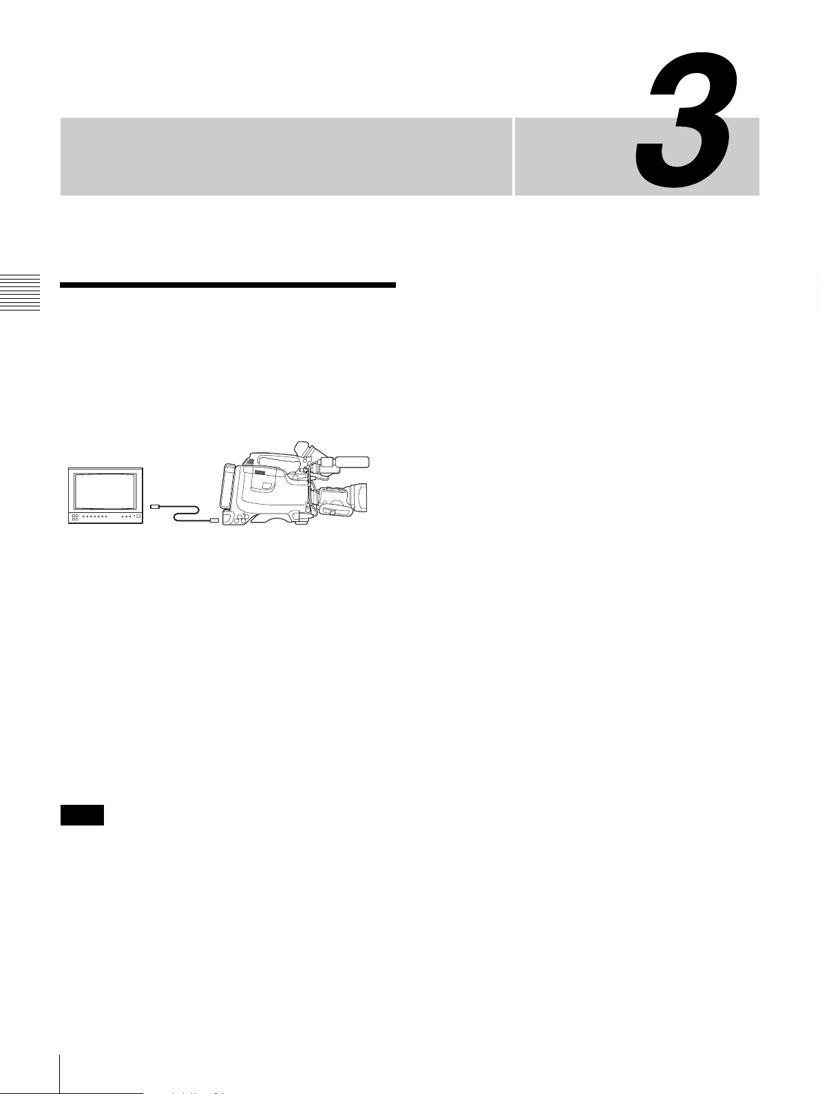
Connections
Chapter 3 Connections
Connecting a Monitor
As illustrated below, you can connect a color video
monitor to the MONITOR OUT or VIDEO OUT
connector of the camcorder.
DSR-400/400P/450WS/450WSP
Color video monitor
1)
VIDEO IN connector
or SDI IN connector
(DSR-450WS/450WSP
2)
only)
1) When VBS is selected as the output signal of the VIDEO OUT connector
2) When SDI is selected as the output signal of the VIDEO OUT connector
(only when a CBK-SD01 is installed)
MONITOR OUT connector
or VIDEO OUT connector
(DSR-450WS/450WSP
only)
Chapter
The items displayed on a monitor are same as the ones on
the viewfinder. For details, see
viewfinder screen” on page 21.
“Status display on the
When a CBK-SD01 SDI Output Board is installed
(DSR-450WS/450WSP only)
If a color video monitor provided with an SDI input
connector is used, select SDI as the output signal of the
VIDEO OUT connector and connect the camcorder to the
SDI IN connector of the color video monitor.
The camera display image is output to the CBK-SD01 SDI
Output Board even when playing a recorded image.
Notes
• Playing the tape on the camcorder mutes the audio signal
portion of the SDI output.
• You can select either VBS or SDI for the output signal
of the VIDEO OUT connector, depending on the input
connector used on the monitor. See 1) and 2) in the
illustration above.
For details about settings, see “Selecting the output
signals (DSR-450WS/450WSP only)” on page 104.
40
Connecting a Monitor
Page 41
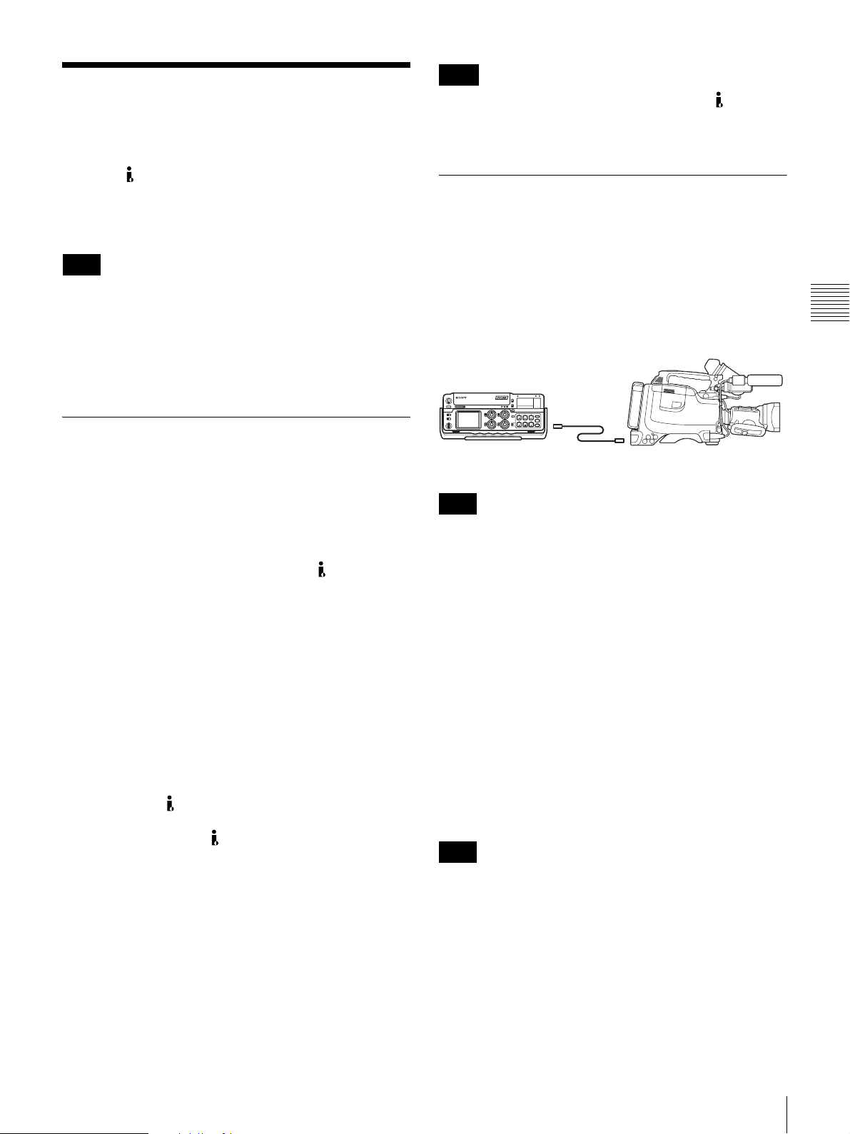
Using an i.LINK
Connection
Using the (i.LINK) DV OUT connector, you can
connect external recording equipment to the camcorder. In
this section, connections to equipment using DVCAM or
DV format are explained.
Note
Depending on the equipment connected, you may be able
to record in a format different from that of the camcorder.
However, the recording function using different formats is
limited.
Note
When there is no equipment connected to the (i.LINK)
DV OUT connector on the camcorder, the setting of the
REC TRIGGER switch does not affect the internal VTR.
Making a backup of the images
being recorded
The audio and image being recorded can be backed up on
an external VTR through i.LINK, at the same time it is
being recorded on the camcorder.
Example of connection
DSR-400/400P/450WS/450WSP
Chapter 3 Connections
For details, see “Usable cassettes” on page 47.
Settings required for an i.LINK
connection
When connecting via an i.LINK cable (DV cable), change
the following settings depending on the connection.
i.LINK CTL setting
Selects whether or not to control recording (start and stop)
on the external equipment connected to the
OUT connector from the camcorder. Select the setting
from the following on the FUNCTION 3 page of the
MAINTENANCE menu. The factory setting is REC/P.
ALL: An external equipment is controlled from the
camcorder while it records, pauses, or stops.
REC/P (REC/PAUSE): An external equipment is
controlled from the camcorder while it records or
pauses.
OFF: No control from the camcorder.
REC TRIGGER switch
Sets the function of the REC button on the camcorder or
the VTR button on the lens when an external VTR is
connected to the
INT ONLY when you need to do cut editing or making a
copy of a tape using the
PARALLEL: Operates both internal and external VTRs
simultaneously.
INT ONLY: Operates the internal VTR only. External
VTR operation is performed locally.
EXT ONLY: Operates the external VTR only. The
TALLY indicator on the camcorder lights up when
the external VTR is in recording mode.
(i.LINK) DV OUT connector. Set to
(i.LINK) DV OUT connector.
(i.LINK) DV
External VTR
i.LINK cable
(DV cable)
DSR-50/PD170, etc.
Note
When the scan mode is 24P, video images, audio, or time
code output via the i.LINK connection may not be
continuous (DSR-450WS only).
To record the same material using the
internal VTR of the camcorder and on an
external VTR simultaneously
1
Set the REC TRIGGER switch to PARALLEL.
2
Check the settings of an external VTR and set the
i.LINK CTL to the same settings.
3
Press the REC button.
Recording starts on both the internal VTR of the
camcorder and the external VTR.
Note
If recording on the camcorder and the external VTR starts
at the same time, the recording starting points differ
because of variation due to the external VTR connected.
Also, it is recommended that you use internal mode as the
time code generator mode for an external VTR. If you
synchronize the time code generator of the camcorder
using external mode, the time code may not be continuous.
Using an i.LINK Connection
41
Page 42
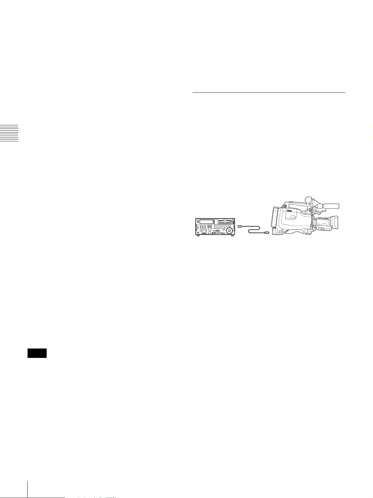
To record by clip using the internal VTR
while simultaneously recording on an
external VTR
While recording material consecutively by time on an
external VTR, the material needed for editing can be
recorded clip by clip using the internal VTR of the
camcorder.
1
Set the REC TRIGGER switch to INT ONLY.
2
Press the recording button of the external VTR.
Recording starts on the external VTR.
3
Chapter 3 Connections
Press the REC button on the camcorder.
Recording starts on the internal VTR. Pressing the
REC button switches between recording and pausing
using the internal VTR.
To check the playback image recorded on
an external VTR
You can check the playback image recorded on an external
VTR that is connected to the camcorder for backup.
1
Connect the camcorder to the external VTR using an
i.LINK cable (DV cable).
2
Set the REC TRIGGER switch to PARALLEL or EXT
ONLY.
3
Press the STOP button on the camcorder to set the
internal VTR of the camcorder to stop mode, or press
the EJECT button to eject the cassette.
4
Start playback on the external VTR.
The i.LINK on the camcorder changes to input mode,
and the playback image from the external VTR is
displayed on the viewfinder and the LCD monitor, and
through the MONITOR OUT connector.
• In order to check the video image when a DSR-1500A/
1800A/2000A or similar equipment is connected to the
camcorder, it is necessary to set the input to a setting
other than i.LINK. When the input is set to i.LINK,
i.LINK is only used for input and no signal is output via
the i.LINK connection. Therefore, a gray image is
displayed on the camcorder.
Using the camcorder as a feeder
To copy digitally from the camcorder to the
VTR without the editing function
Using an i.LINK cable (DV cable) to connect a digital
video cassette recorder with an i.LINK connector to the
camcorder, digital copy of video and audio can be carried
out.
Example of connection
DSR-400/400P/450WS/450WSP
External VTR
DSR-1800A/45, etc.
1
Make the settings below to prepare the external VTR.
• Set REC MODE to the same recording mode as that
of the camcorder.
• In NTSC color system, when the recording mode is
set to DVCAM, select either DF or NDF.
• Set AUDIO MODE to either 4-channel or 2-channel
mode, according to the tape that is played on the
camcorder.
2
Pause recording on the external VTR.
i.LINK cable
(DV cable)
Notes
• The i.LINK on the camcorder changes to input mode
only when the connected external equipment is played
back. (When the REC TRIGGER switch is set to INT
ONLY, the i.LINK does not change to input mode.)
• The playback image from the external VTR cannot be
recorded using the internal VTR of the camcorder.
• Depending on the external equipment connected, the
playback image may be overlapped or skipped over if the
playback signal contains jitter. However, this is not a
malfunction.
42
Using an i.LINK Connection
3
Play the tape on the camcorder.
4
Check the playback on the camcorder, and when
playback reaches the scene that you want to record,
start recording again on the external VTR.
The copy to the external VTR starts.
5
When copy to the external VTR is finished, release the
recording pause on the external VTR, and then stop
playback of the tape on the camcorder.
For details on the external VTR, see the instruction manual
supplied with the external VTR.
Page 43
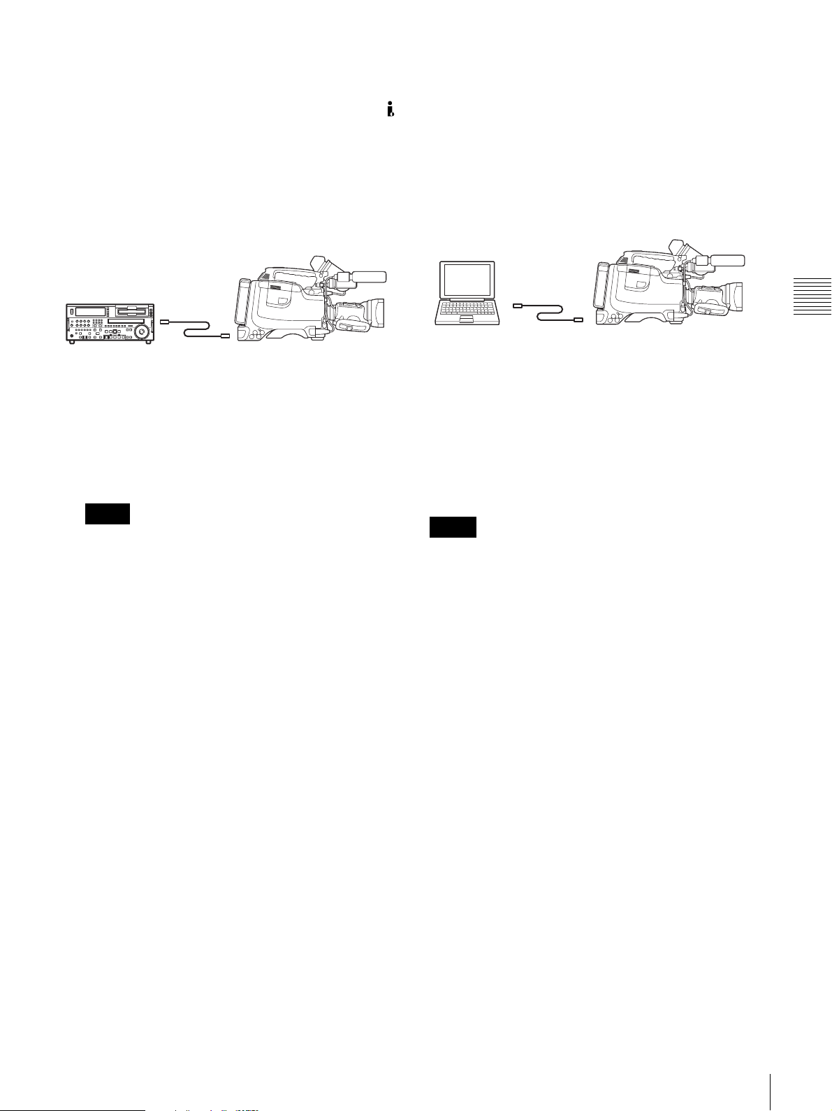
To control the camcorder from the VTR
using the editing function
By connecting a VTR with an i.LINK connector to the
(i.LINK) DV OUT connector of the camcorder using an
i.LINK cable (DV cable), you can control playback and
recording of the camcorder and perform cut editing and
digital copy.
Example of connection
DSR-400/400P/450WS/450WSP
External VTR
DSR-2000A, etc.
1
Set the REC TRIGGER switch to INT ONLY.
2
Make the settings below to prepare the external VTR.
When using DSR-2000A, press the i.LINK button on
the remote control setting section.
i.LINK cable
(DV cable)
To control the camcorder from a non-linear
editing system
Using the i.LINK cable (DV cable), you can transfer video
and audio signals to a non-linear editing system from the
camcorder. Editing software that supports the selected
recording format (DVCAM or DV) must be used.
Example of connection
DSR-400/400P/450WS/450WSP
PC
i.LINK cable
(DV cable)
Computer with editing
software that supports
DVCAM or DV format
installed
1
Set the REC TRIGGER switch to INT ONLY.
2
Operate the PC to set up the non-linear editing
software.
For details, see the software’s manual.
Chapter 3 Connections
Note
To use the automatic copying function of DSR-2000A,
it is necessary to set the recording format of the
camcorder to DVCAM on the VTR MODE page of the
MAINTENANCE menu.
For details on the external VTR, see the instruction
manual supplied with the external VTR.
Notes
• Video edited using a non-linear editing system cannot be
recorded on tape using the camcorder via an i.LINK
cable (DV cable).
• A tape recorded with a non-continuous time code may
not be able to be captured frame by frame using a nonlinear editing system.
Using an i.LINK Connection
43
Page 44
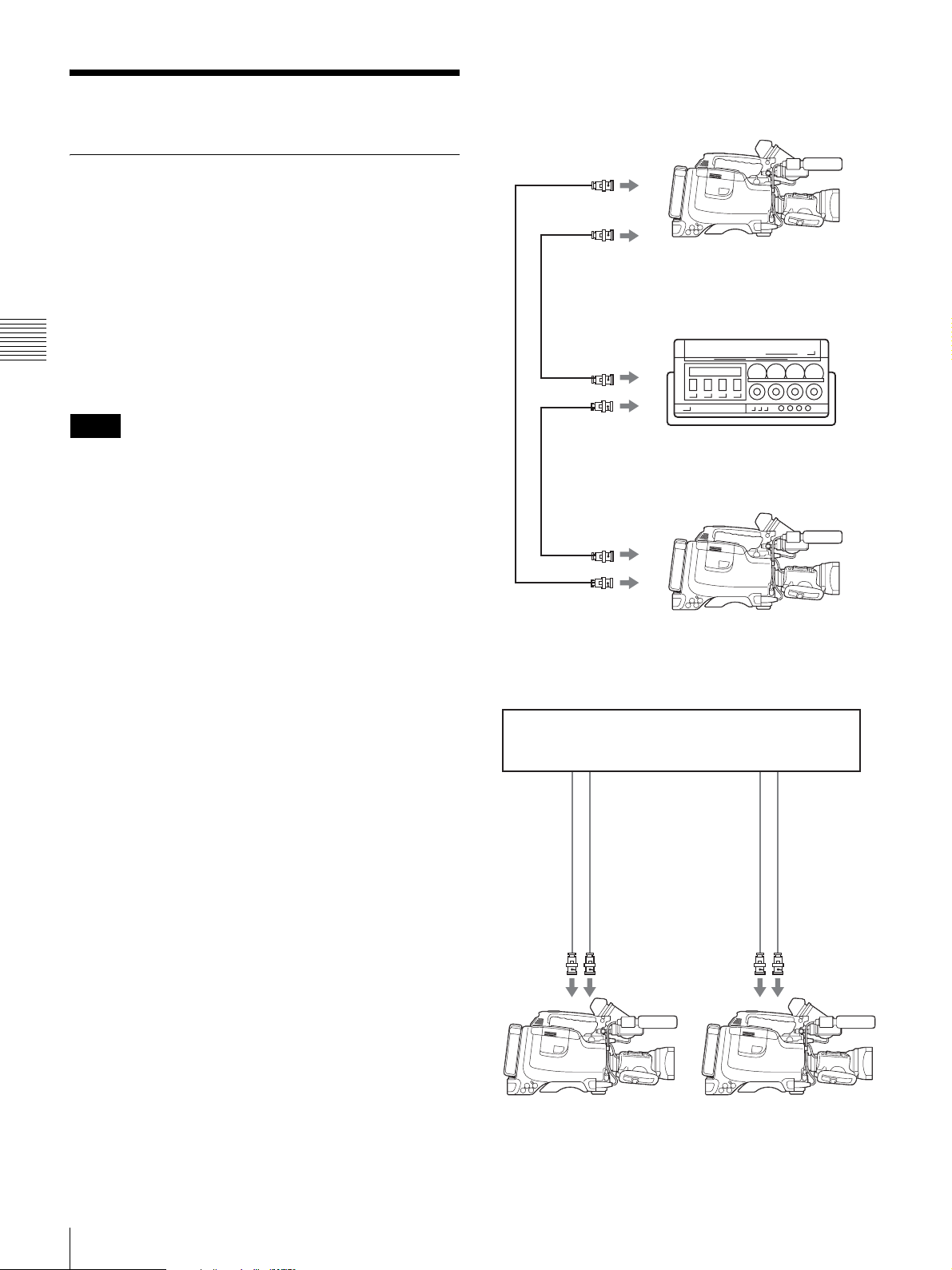
Other Connections
Example 1: When camcorder 2 is synchronized with
the signal of camcorder 1
DSR-450WS/450WSP
Connecting a number of camcorders
When using two or more synchronized camcorders,
connect an external sync signal to the GENLOCK IN
connector, supplying a VBS or BS signal. The camcorder
will then operate synchronized to this signal.
You can adjust the synchronization using the GENLOCK
page of the MAINTENANCE menu.
When a CBK-SD01 SDI Output Board is installed in the
DSR-450WS/450WSP, it is necessary to set REAR BNC
Chapter 3 Connections
OUT SEL to VBS on the OUTPUT page of the
OPERATION menu.
Notes
• When a CBK-SC01 Composite Input Board (not
supplied) is installed, set REC VIDEO SOURCE to
CAM on the SOURCE SEL page of the OPERATION
menu.
• When connecting a number of camcorders and
synchronizing their time codes, wait until the reference
camcorder becomes stable (a state where a normal
picture appears on the viewfinder or the LCD monitor),
and then connect the other camcorders.
BNC cable
BNC cable
BNC cable
to VIDEO OUT
to MONITOR OUT
to video input
connector
to video input
connector
to MONITOR OUT/
VIDEO OUT
to GENLOCK IN
Camcorder 1
Portable VTR
DSR-400/400P/450WS/450WSP
Camcorder 2
Example 2: When camcorder 1 and 2 are synchronized
with the signal of a DME switching device, etc.
DME switching device, etc.
to video
input
connector
BNC cable
to
MONITOR/
VIDEO OUT
DSR-400/400P/450WS/450WSP
Camcorder 1
* Either the BB (Black Burst) signal or the Color Bar signal, etc. can be used
as a synchronized signal.
to synchronized
signal output
connector *
BNC cable
to GENLOCK
IN
to video
input
connector
BNC cable
to MONITOR/
VIDEO OUT
DSR-400/400P/450WS/450WSP
to synchronized
signal output
connector *
BNC cable
to GENLOCK
IN
Camcorder 2
44
Other Connections
Page 45
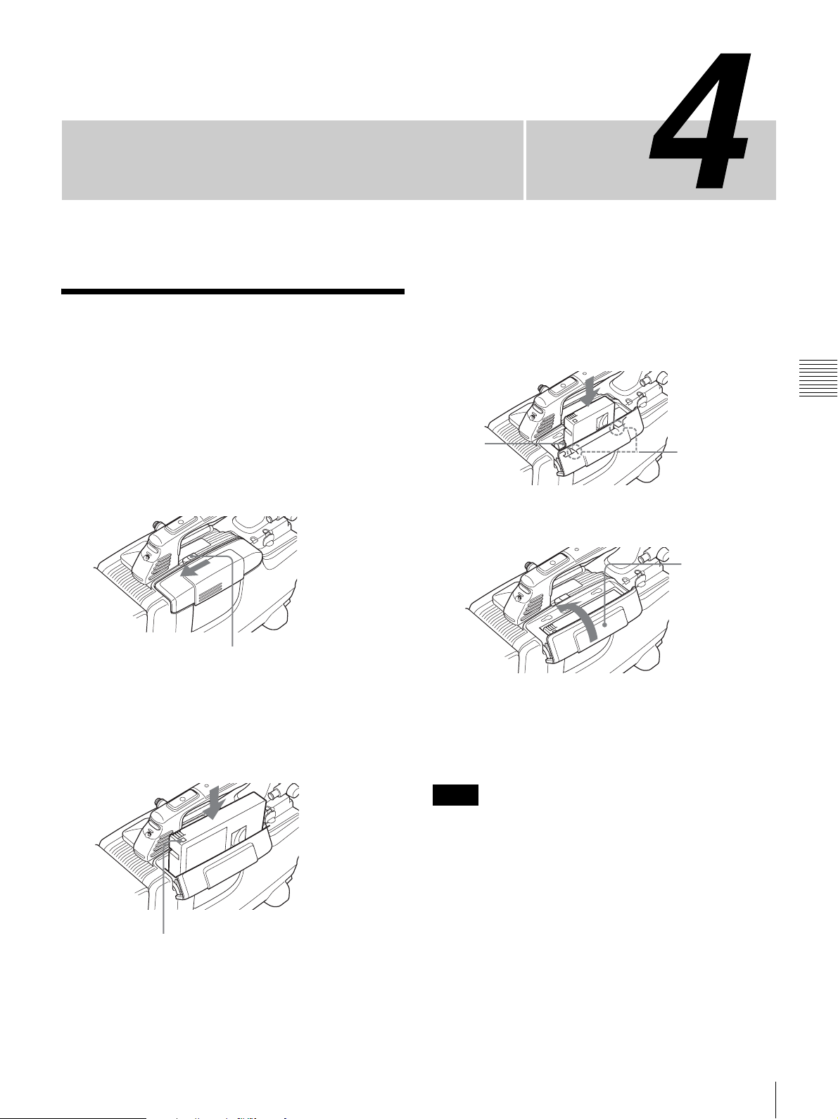
Recording and Playback
To insert a mini-size cassette
Inserting a Cassette
The camcorder can use standard-size and mini-size
DVCAM/DV cassettes. For details about usable cassette,
“Usable cassettes” on page 47.
see
1
Set the POWER switch to ON.
2
While sliding the OPEN lever in the direction of the
arrow, open the cassette lid.
Insert the cassette with the cassette window (on the
front) facing outward. Push the cassette between the
both guides.
Guides
4
Close the cassette lid until it clicks.
Chapter
Chapter 4 Recording and Playback
Mini-size cassette
match marks
Top of the lid
OPEN lever
3
Insert the cassette with the cassette window (on the
front) facing outward and the REC/SAVE switch
facing upward.
Check for tape slack before inserting the cassette.
Press the center
of the cassette.
REC/SAVE switch
Press the lid firmly
until it clicks.
If the cassette lid
is hard to close,
press the top of
the lid.
To eject a cassette
Follow the procedure above, and take out the cassette by
pressing the EJECT button in step 3.
Notes
• Before inserting a cassette, make sure that there is no
cassette in the cassette compartment. Inserting two
cassettes by mistake may cause a malfunction.
• Internal parts of the camcorder may become bent or
otherwise damaged if you attempt to insert a mini-size
cassette in the wrong direction (such as with the cassette
turned backside front so the reel holes face the cassette
holder window or with the cassette turned sideways so
that a short side enters first).
• If a cassette is not inserted completely or gets stuck when
being inserting, take out the cassette and reinsert it. If
your insert a cassette forcibly, the cassette may not be
Inserting a Cassette
45
Page 46
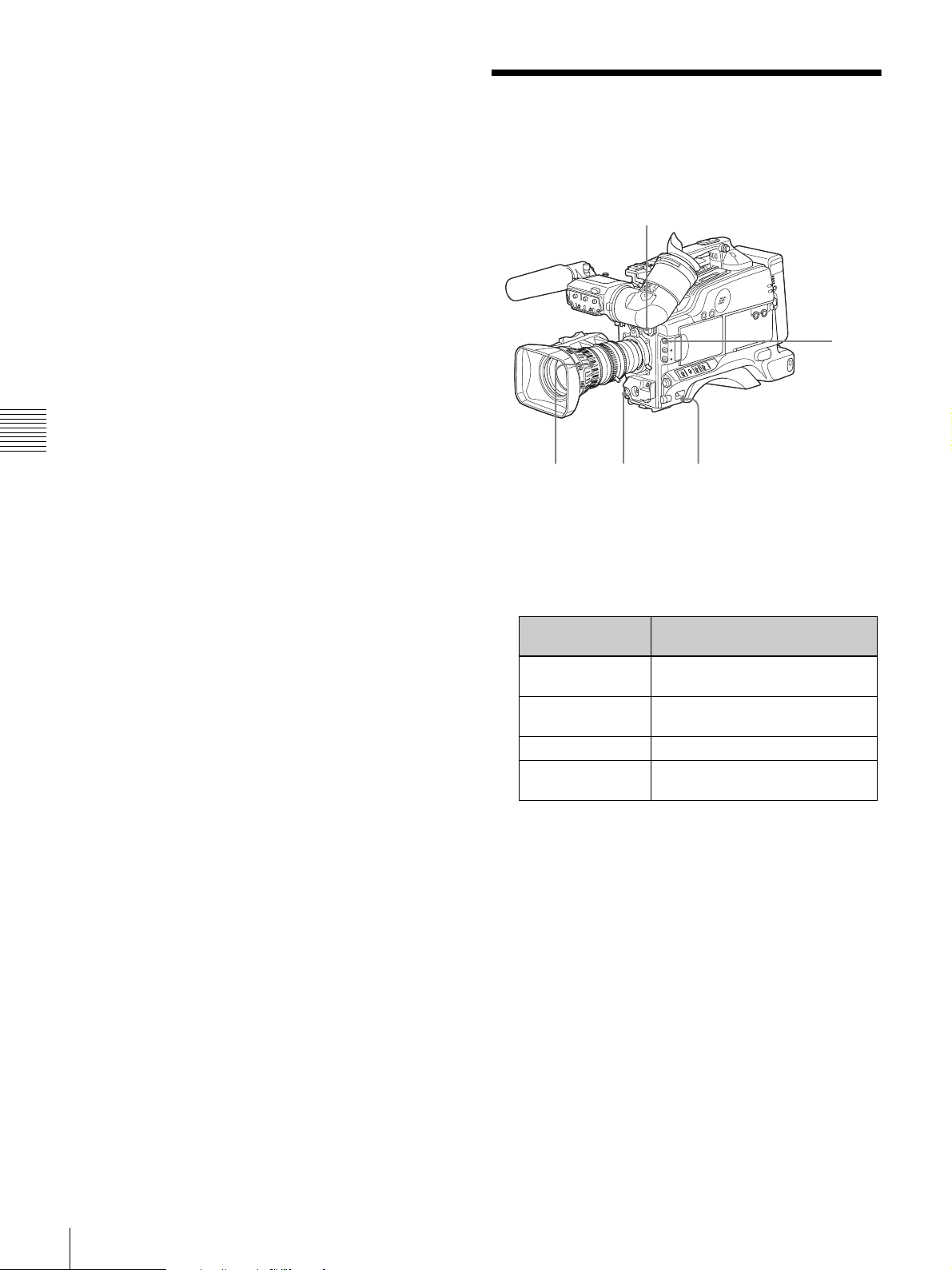
inserted in the correct position or may cause a
malfunction.
• When inserting a cassette, hold the center of the cassette
and insert it straight toward the compartment. Holding
the side of the cassette may cause it to be inserted
incorrectly.
• When inserting a cassette, put the camcorder on a
horizontal and stable surface.
Chapter 4 Recording and Playback
Basic Procedure for
Shooting
2
8
11
12,13
1
Set the POWER switch to ON.
2
Set the FILTER selector and the 5600K button
appropriately for the lighting conditions.
FILTER selector
setting
1 (CLEAR) Studio halogen lighting
2 (1/4 ND) Cloudy or rainy outdoor shooting,
3 (1/16 ND) Sunlight
4 (1/64 ND) To reduce the depth of field in
* The range over which the subject is sharply in focus. Thus, “reducing
the depth of field” means that the range is reduced as well, and
“increasing the depth of field” means that it is increasing as well.
3
Check the switch settings on the camcorder.
4
Check the settings in the menu.
1
Examples of shooting
conditions
(incandescent)
or to reduce the depth of field*
sunlight
46
Basic Procedure for Shooting
5
Check the lens settings and flange focal length
adjustment
6
Adjust the eyepiece focus, and the contrast and
brightness of the viewfinder image
7
Check the sound system settings.
• Microphone connections (page 34)
• Settings on the VTR section (page 14)
(page 28).
(page 30).
Page 47
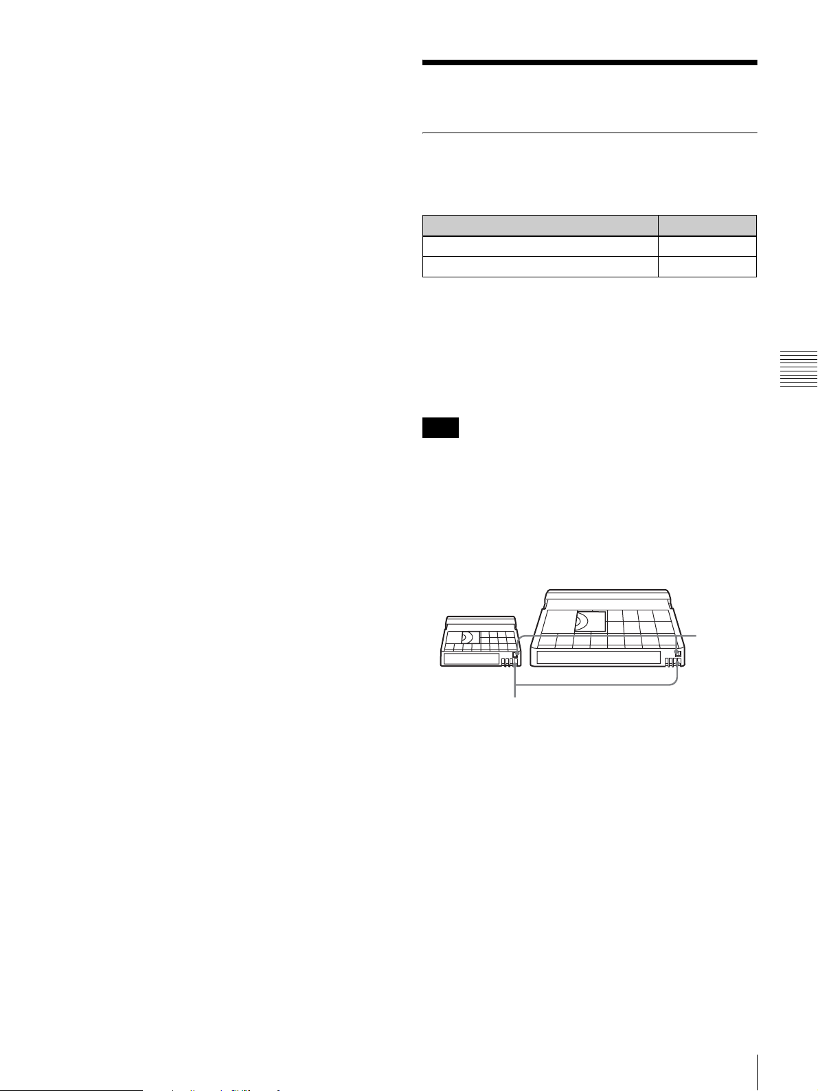
8
If required, switch on the center marker and/or safety
zone in the viewfinder image.
For details, see “Setting the marker display” on page
100.
Recording
Also, press the ZEBRA button to display zebra pattern
in the viewfinder.
9
If necessary, adjust the white balance and black
balance
10
If necessary, adjust the iris and gain.
For details about the adjustment of iris, see “Iris ring”
on page 19, “Instant automatic iris adjustment
button” on page 19, and “Adjusting the iris” on page
55.
For details about the adjustment of gain, see “GAIN
switch” on page 11, and “Setting gain values for the
GAIN switch positions” on page 103.
11
Turn the focusing ring so that the subject is sharply in
focus.
12
Setup the VTR section according to your shooting
objects, then start recording by pressing the REC
button.
• During recording, the REC/TALLY indicator(s) in
• You can use the AUDIO LEVEL knob on the front
(page 50).
the viewfinder light(s), and “REC” appears on the
viewfinder screen.
of the camcorder to manually adjust the channel 1
audio level. To do this, you must first set up the VTR
section to enable manual adjustment of the audio
recording level
(page 57).
Usable cassettes
It is recommended to use the DVCAM cassettes listed
below for this camcorder.
Model name Size
PDV-184*/124*/94*/64*/34* Standard size
PDVM-40*/32*/22*/12* Mini size
The “*” in each model name is actually “ME” (indicating
that a cassette memory is contained), or “N” (indicating
that no cassette memory is contained).
The numbers in the model names show maximum
recording/playback time (minutes) for each model. For
example, the maximum recording/playback time of the
PDV-184* is 184 minutes.
Note
If you insert an incorrect type of cassette, it will be
automatically ejected.
DVCAM cassettes
The following figure illustrates the DVCAM cassettes’
appearance.
Standard size
Mini size
REC/SAVE
switch
Chapter 4 Recording and Playback
13
To pause recording, press the REC button again.
Cassette memory
Notes on using cassettes
• Before storing the cassette, rewind the tape to the
beginning and be sure to put the cassette in its storage
case, preferably on end instead of flat on its side. The
storage case of a DVCAM cassette is specially designed
to ensure a long-period storage of the tape. Storing a
cassette in any other condition (not rewound, out of its
case, etc.) may cause the video and audio contents to
become damaged over time.
• If the cassette memory connector (contact point)
becomes dirty, connection problems may occur and
cause a loss of functions. Remove away any dust or dirt
from this area before using the cassette.
• If the cassette is dropped on the floor or otherwise
receives a hard impact, the tape may become slackened
Recording
47
Page 48
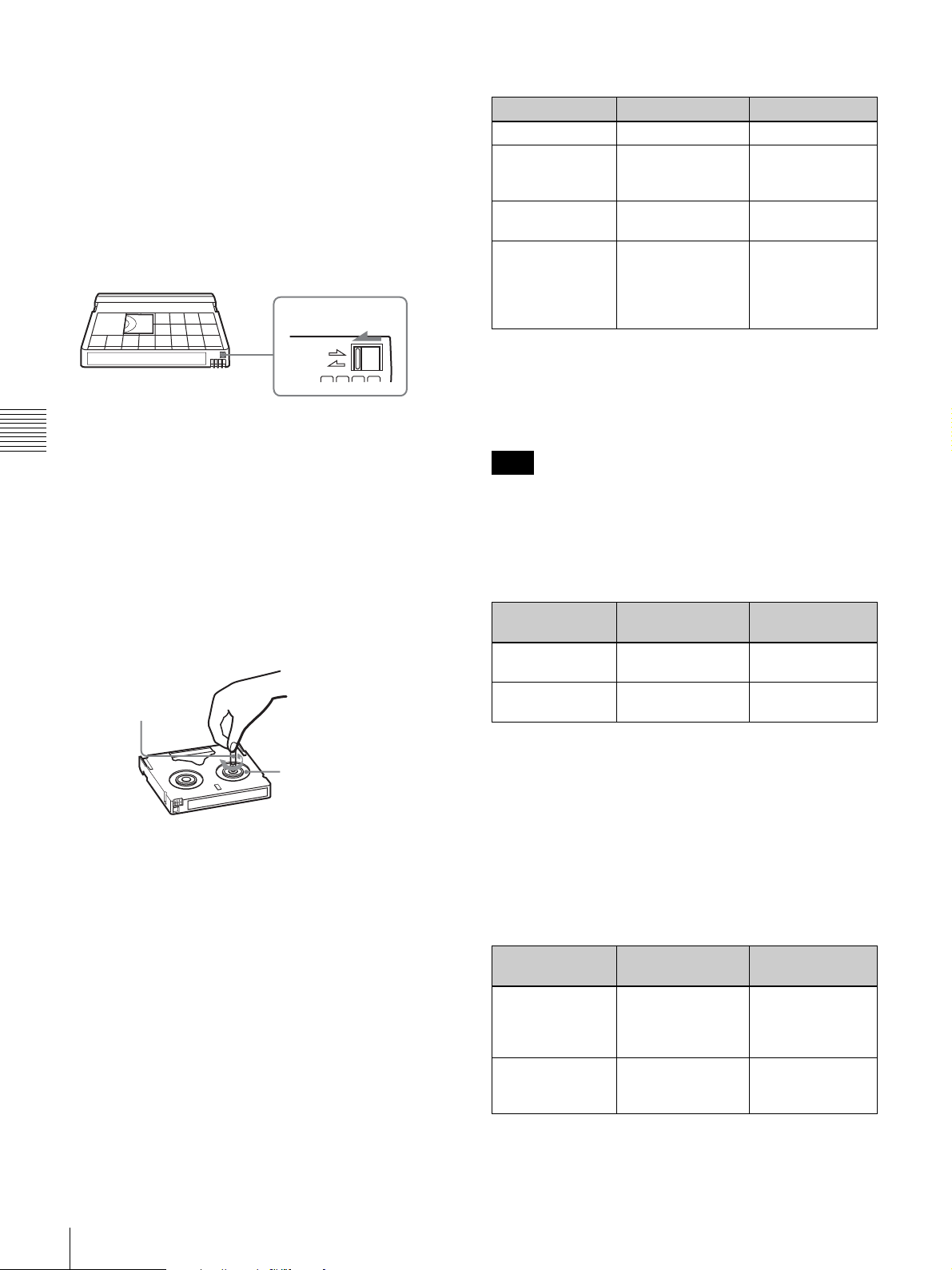
and may not record and or play back correctly. For
instructions on removing tape slack, see next page.
• Follow the instructions in “Inserting a Cassette” on
page 45 to insert a cassette, or the camcorder may be
damaged.
To prevent accidental erasure
Set the REC/SAVE switch to SAVE to prevent accidental
erasure of recorded contents.
REC/SAVE switch
Set to SAVE.
Differences between DVCAM and DV formats
Item DVCAM DV
Track pitch 15 µm 10 µm
Audio sampling
frequency
Audio recording
mode*
Time code Drop frame system
12 bit: 32 kHz
16 bit: 48 kHz
Lock mode Unlock mode
or
Non-drop frame
system (SMPTE
time code)
12 bit: 32 kHz
16 bit: 32 kHz,
44.1 kHz, 48 kHz
Drop frame
system (or Nondrop frame system
when recording in
DV format)
REC
SAVE
If you insert a cassette into the camcorder when the REC/
SAVE switch is set to SAVE, the camcorder will not
Chapter 4 Recording and Playback
record when you press the REC button.
To enable recording
Set the REC/SAVE switch back to REC.
To check the tape for slack
Turn the reel gently with a paper clip, etc., in the direction
shown by the arrow. If the reel does not move, there is no
slack. Insert the cassette into the cassette holder, and after
about 15 seconds take it out.
Paper clip, etc.
Reel
Compatibility of DVCAM and DV formats
This camcorder can also use the consumer DV format in
addition to the DVCAM format (only SP mode is available
for DV format, you cannot record/play in LP mode of the
DV format). Here explained are the differences,
compatibility, and limitations on editing about DVCAM
and DV formats.
* There are two modes for audio recording, lock mode and unlock mode. In
lock mode, the sampling frequencies of audio and video are synchronized.
In unlock mode, which consumer DV format adopts, the two sampling
frequencies are independent. Therefore, lock mode is more effective than
unlock mode in digital processing and smooth transition during audio
editing.
Note
Audio with sampling frequency 16 bit: 32 kHz and 44.1
kHz cannot be recorded on this camcorder.
Compatibility on cassettes
The recording format of picture is defined according to
recorder’s format as described below.
Recorder’s
format
DVC A M DVCAM ta p e
DV DV C A M tape
Cassette that is
used
DV t a p e
DV t a p e
Recording
format
DVC A M
DV
• Though DV cassettes can be used for recording in
DVCAM format, we recommend you to use DVCAM
cassettes to get the most out of high reliability of
DVCAM format.
• When you record using DV cassettes in DVCAM
format, the recording time of DV cassettes is
2/3 shorter
than that indicated on the DV cassettes.
Compatibility on playback
Some tapes cannot be played back on DVCAM or DV
video equipment.
Tape On DV video
equipment
DV-formatted Can be played
back.
DVC A Mformatted
Some equipment
may be able to play
back.
On DVCAM video
equipment
Can be played
back only when
recorded in SP
mode.
Can be played
back.
48
Recording
Page 49
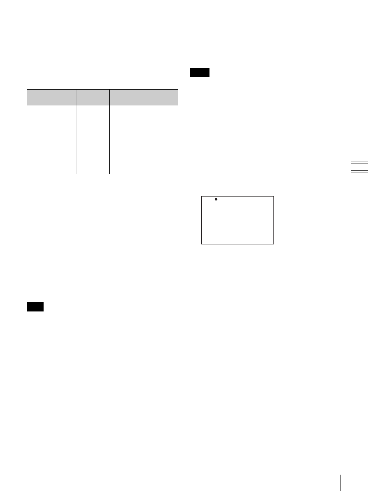
Compatibility on editing using DV connectors
When this digital camcorder is connected to other
DVCAM or DV video equipment using DV cable (i.LINK
cable), the recording format of edited tapes is defined
according to recorder’s format as described below. Read
through
“Limitations on editing” before editing, because
you may find the limitations when you use the tapes edited
in some conditions.
Source tape Player’s
format
DV
(only in SP mode)
DV DV DVCA M
DVC A M
DVC A M
1) When using the DVCAM video equipment to carry out DV dubbing of a
2) If the tape that is to be dubbed is DVCAM formatted tape as explained in
3) Some DV video equipment may be able to play back a DVCAM-formatted
4) The audio recording mode of the edited tape is lock mode. If the tape that
5) Depending on model of video equipment, you may not be able to edit.
Note
2)
2)
tape recorded in DV format, the tape produced will be in DVCAM format
as follows:
- Audio recording mode will be unlock mode.
(A tape in lock mode may be copied on some video equipment. For
details, see the instruction manual supplied with your video equipment.)
- The time code format will be partly maladjusted. (There will be no
effect on the recorded picture except in certain case.)
1), the tape produced will be in DVCAM format as follows:
- Audio recording mode will be unlock mode.
- The time code format will be partly maladjusted.
tape. However, even if the tape is played back, contents of the playback
cannot be guaranteed. Therefore, if an appropriate DVCAM-formatted
tape is used for playback, the tape produced will be in DVCAM format and
will have a partly maladjusted time code format.
is to be dubbed is a DVCAM formatted tape as explained in 1), the audio
recording mode of the edited tape is unlock mode.
DVC A M DVCAM
DVC A M DVCAM
3)
DV
Recorder’s
format
DV
DV
DV
DVCA M
DV
Recording
format
DVC A M
DV
DVC A M
DV
DVC A M
DV
DVC A M
DV
1)
1)
4)
5)
4)
When you use a tape as explained in 1) to 3) above, you
may find limitations regardless of the format of the player
and recorder.
Selecting the recording format
Before recording, it is necessary to select the recording
format from either DVCAM or DV SP format.
Notes
• If recording formats are mixed in one tape, the part
where the video images recorded in different formats
will be distorted.
• When shooting in DV SP format, the video recorded in
back space editing (recording several scenes
continuously) may not be smooth. To shoot reliable
video, it is recommended that you use a DVCAM
cassette and set REC FORMAT to DVCAM (see the
following procedure).
1
Display the VTR MODE page of the
MAINTENANCE menu.
For details on menu operations, see “Basic menu
operations” on page 93.
?M05 VTR MODE TOP
REC TALLY BLINK : ON
STBY OFF TIMER : 1MIN
REC FORMAT : DVCAM
SETUP ADD : ON
2
Press the MENU knob. Then turn the MENU knob to
move b to REC FORMAT, and press the MENU knob
again.
b changes to z, and z changes to ?.
3
Turn the MENU knob to display the desired recording
format (DVCAM or DV SP), then press the MENU
knob.
z changes to b, ? changes to z, and the selection is
set.
Chapter 4 Recording and Playback
Limitations on editing
When using a tape copied or edited using DV connectors,
you will find the following limitations when editing,
because of the difference in DVCAM and DV formats.
• Due to the difference of a track pitch, you cannot edit on
DV-formatted tapes using DVCAM video equipment.
• You cannot edit DVCAM-formatted tapes recorded in
unlock mode using some DVCAM video equipment. In
this case, copy the tape again using the audio/video
jacks.
Recording
49
Page 50
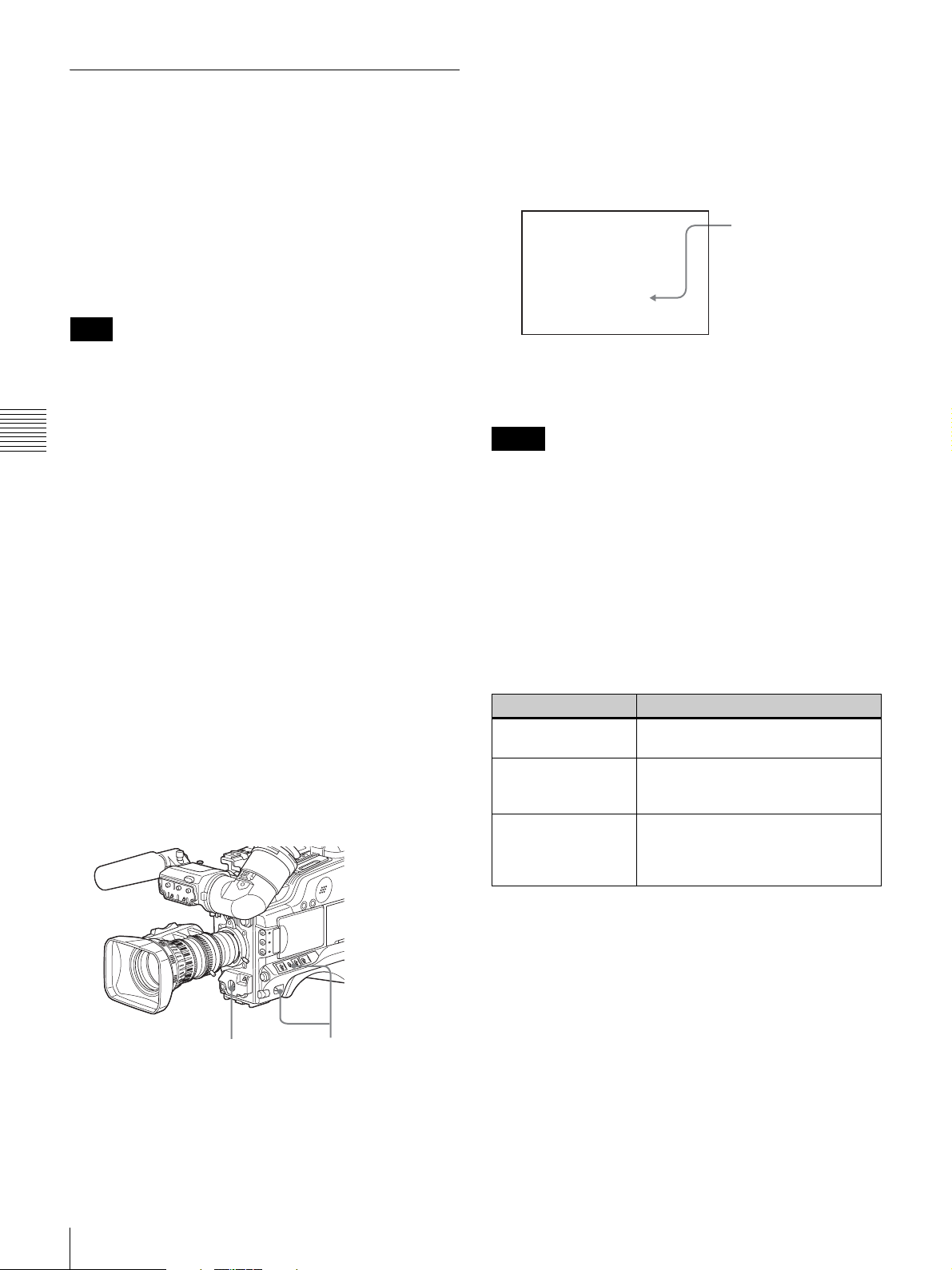
Adjusting the black balance/white
balance
To ensure excellent image quality when using this
camcorder, conditions may require that both the black
balance and the white balance be adjusted.
If the black balance or white balance adjustment is started,
messages that report on the progress and results are
displayed on the viewfinder screen when the VF DISP
MODE item is set to 2 or 3 on the VF DISP 1 page of the
OPERATION menu.
Note
2
Push the AUTO W/B BAL switch to BLACK and
release the switch.
The switch returns to the center position, and the
adjustment is executed.
During adjustment, the following message is displayed
on the viewfinder screen.
The messages change in
sequence:
-BLACK SET r
ABB:EXECUTING
-BLACK SET-
-BLACK BALANCE-
Black balance and white balance adjustment values that
are automatically set by the camcorder and the various
settings are stored in the camcorder memory and retained
even when the power is turned off.
Chapter 4 Recording and Playback
To adjust the black balance
The black balance will require adjustment in the following
cases.
• When the camcorder is used for the first time
• When the camcorder has not been used for a long time
• When the camcorder is used under conditions in which
the surrounding temperature has changed greatly
• When the GAIN switch (L/M/H) values have been
changed by using the OPERATION menu
It is not usually necessary to adjust the black balance when
using the camcorder after it has been off.
In automatic black balance mode, adjustments are
performed in the following order: clamp level, black set,
and black balance.
Note that the automatic black balance adjustment
includes a function to correct minor bright or dark
points of light (red, blue, or green) that appear on the
CCDs, in addition to the normal black balance
operation.
The black balance adjustment ends in a few seconds
with the message “ABB: OK” and the adjustment
value is automatically stored in memory.
Notes
• During the black balance adjustment, the iris is
automatically closed.
• During the black balance adjustment, the gain selection
circuit is automatically activated so you may see
flickering on the viewfinder screen, but this is not a
malfunction.
If automatic black balance adjustment cannot be
made
If the black balance adjustment cannot be completed
normally, an error message will appear for about 3 seconds
on the viewfinder screen.
Error message Meaning
ABB: NG
IRIS NOT CLOSED
ABB: NG
TIME LIMIT
ABB: NG
R (or G or B):
OVERFLOW
The lens iris did not close. Check if
the lens cable is connected properly.
Adjustment could not be completed
within the standard number of
attempts.
The difference between the
reference value and the current
value is so great that it exceeds the
range.
50
2
1
Power the camcorder on, and set the OUTPUT/DCC
1
switch to CAM.
Recording
If any of the above error messages is displayed, retry the
black balance adjustment. Keep pushing the AUTO W/B
BAL switch to BLACK until “-BLACK SET-” appears
after “-BLACK BALANCE-” appears. If the error
message occurs repeatedly, contact your Sony service
representatives.
Page 51
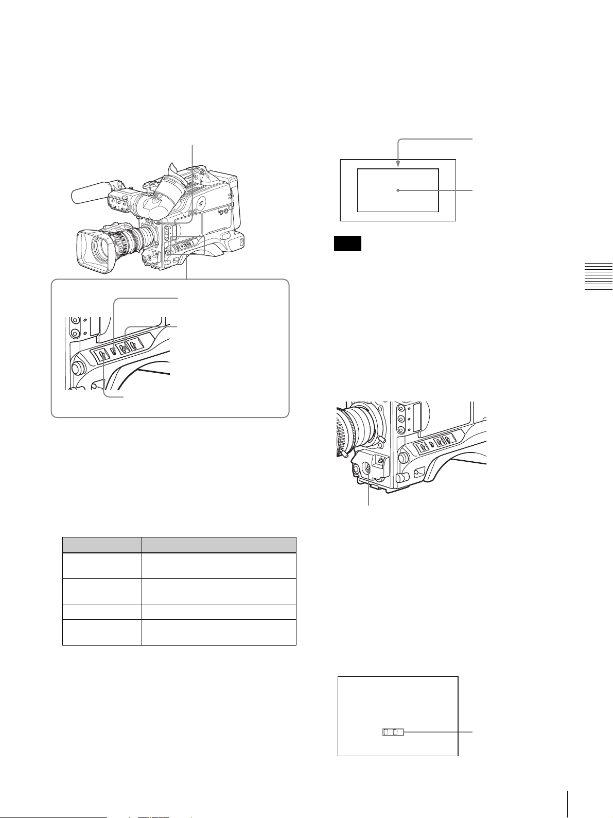
To adjust the white balance
It is necessary to adjust the white balance each time the
principal lighting source changes.
1
Set the switches and selectors as shown in the figure
below.
3
Place a white test card under the same lighting
conditions as for the subject to be shot and zoom up to
it.
Alternatively, any white object such as a cloth or a
wall can be used.
The absolute minimum white area is as follows.
FILTER selector
OUTPUT/DCC switch:
CAM
WHITE BAL switch: A or B*
GAIN switch: Set as low as possible.
Rectangle centered on
the screen. The lengths
of the sides are 70% of
the length and width of
the screen.
The white object must
be within the rectangle
and have an area of at
least 10% of the screen.
Note
Make sure there are not bright spots in the rectangle.
4
Adjust the lens iris.
Manually adjusted lens: Set the iris to an appropriate
setting.
Lens with automatic iris: Set the automatic/manual
switch on the lens to automatic.
5
Push the AUTO W/B BAL switch to WHITE, and then
release the switch.
Chapter 4 Recording and Playback
* White balance setting values are stored in memory B only when the
WHITE SWITCH <B> item is set to MEM on the FUNCTION 2 page
of the OPERATION menu.
2
Set the FILTER selector and the 5600K button to suit
the lighting conditions.
FILTER selector setting and CC filter selection are as
follows.
Filter setting Lighting conditions
1 (CLEAR) Studio halogen lighting
2 (1/4 ND) Cloudy or rainy outdoor shooting, or
3 (1/16 ND) Sunlight
4 (1/64 ND) To reduce the depth of field in
(incandescent)
to reduce the depth of field
sunlight
If the setting of the FILTER selector is changed, a
message reporting the setting appears for about 3
seconds in the setting change and adjustment progress
message display area of the viewfinder screen (when
the display mode is set to 3 on
page 99).
AUTO W/B BAL switch
The switch returns to the center position, and the
adjustment is executed.
During adjustment, the message “AWB:
EXECUTING” is displayed on the viewfinder screen
(when the display mode is set to 2 or 3
(page 99)).
The white balance is adjusted in about one second, and
the message “ABB: OK” appears. The adjustment
setting is automatically stored in the memory (A or B)
that was selected in step 1.
AWB:OK
. K
Approximate color
temperature of the
subject
Recording
51
Page 52
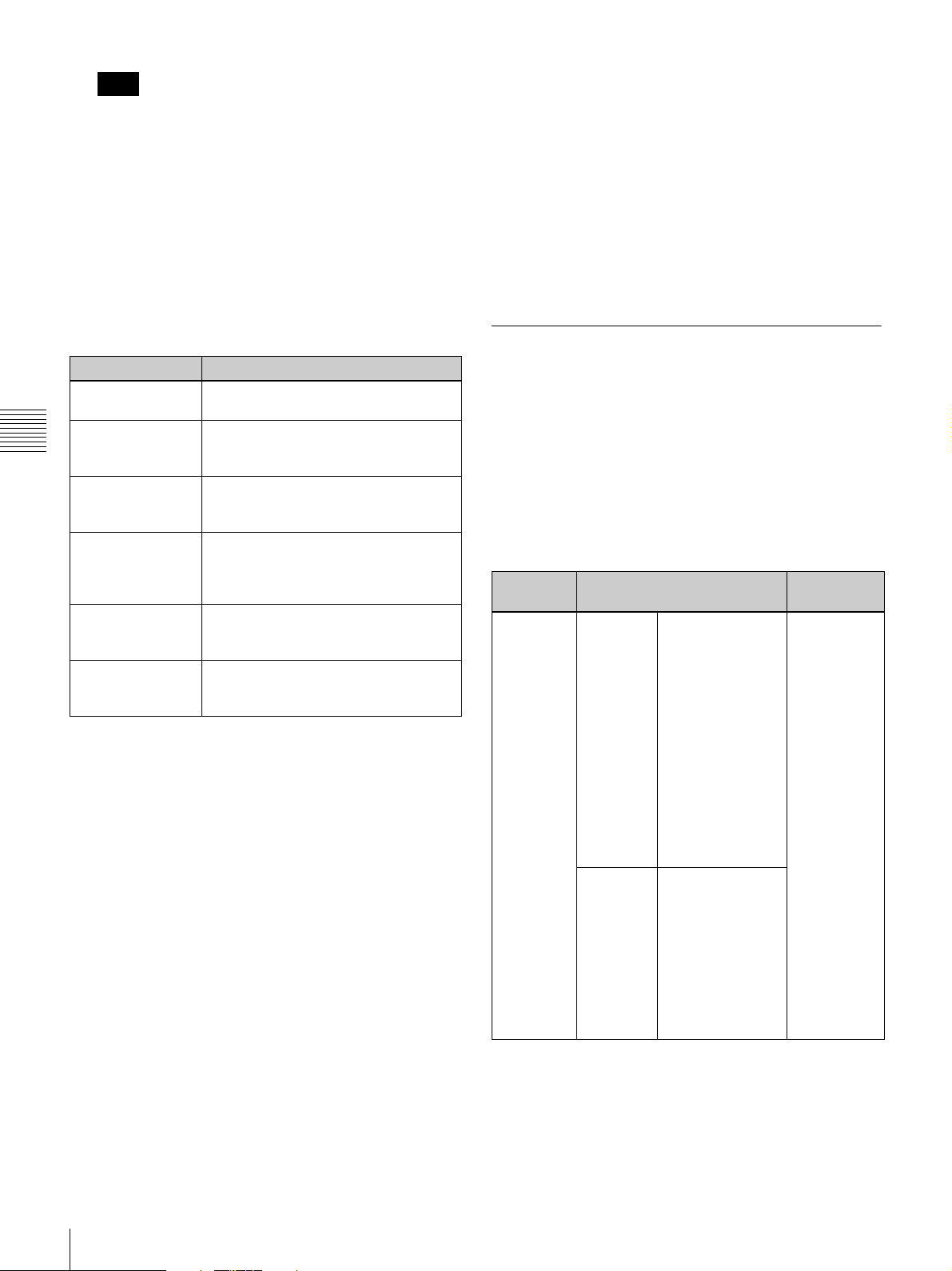
Note
If the camera has a zoom lens with an automatic iris,
the iris may hunt.
*
To prevent this, adjust the iris gain
knob (indicated as IG, IS, or S) on the lens.
For details, refer to the lens operation manual.
* Hunting: Repeated brightening and darkening of the image,
resulting from repeated response to automatic iris control.
If the automatic white balance adjustment cannot
be made
If the white balance adjustment cannot be completed
normally, an error message will appear for about 3 seconds
on the viewfinder screen (in display mode 2 or 3).
Error message Meaning
WHITE: NG
LOW LEVEL
WHITE: NG
COLOR TEMP
Chapter 4 Recording and Playback
HIGH
WHITE: NG
COLOR TEMP
LOW
WHITE: NG
TIME LIMIT
WHITE: NG
POOR WHITE
AREA
WHITE: NG
OVER LEVEL
The white video level is too low. Either
open the lens iris or increase the gain.
The color temperature is too high.
Select a suitable setting for the 5600K
button.
The color temperature is too low. Select
a suitable setting for the 5600K button.
Adjustment could not be completed
within the standard number of
attempts. Try to adjust again. If fails a
few times, contact your Sony dealer.
The white area could not be checked.
The white video level is too high. Either
stop down the lens iris or change the
ND filter.
If any of the above error messages is displayed, retry the
white balance adjustment. If the error message occurs
repeatedly, contact your Sony service representatives.
If you have no time to adjust the white balance
Set the WHITE BAL switch to PRST.
The white balance is automatically set as follows,
depending on the 5600K button setting.
• 5600K ON (lights on): 5600K
• 5600K OFF (lights off): 3200K
About the white balance memory
Values stored in memory are held until the white balance
is next adjusted.
There are two sets of white balance memories, A and B,
and adjustments for each of the filters can be automatically
stored in the memory corresponding to the setting (A or B)
of the WHITE BAL switch. The camcorder has four builtin filters, so a total of eight (4 × 2) adjustments can be
stored. The number of memories allocated to each of A and
B can be limited to one by setting the WHT FILTER INH
item to ON on the FUNCTION 3 page of the
MAINTENANCE menu. In this case, the memory
contents are not linked to the filter settings. If the WHITE
BAL switch is set to B, and on the FUNCTION 2 page of
the OPERATION menu, the WHITE SWITCH <B> item
is set to ATW, the ATW function is activated to
automatically adjust the white balance of the picture being
shot for varying lighting conditions.
If a memory error occurs
If the error message “: STORED DATA: NG” flashes on
the viewfinder screen when the camcorder is turned on, the
white balance memory contents have been lost. Adjust the
white balance again. Contact your Sony representative if
this message continues to appear even after the white
balance have been adjusted again.
Setting the electronic shutter
This section describes the shutter modes that can be used
with the electronic shutter of the camcorder, and describes
the procedure for selecting the shutter speed and shutter
mode.
About the shutter modes
The shutter modes that can be used with the electronic
shutter and the shutter speeds that can be selected are listed
below.
Shutter
mode
Standard DSR-400/
Shutter speed Application
450WS
DSR400P/
450WSP
Scan Mode: I
1/100, 1/125,
1/250, 1/500,
1/1000, 1/2000
(sec.)
Scan Mode: PsF
1/40, 1/60, 1/120,
1/125, 1/250,
1/500, 1/1000,
1/2000 (sec.)
Scan Mode:24P
1/32, 1/48, 1/96,
1/125, 1/250,
1/500, 1/1000,
1/2000 (sec.)
Scan Mode: I
1/60, 1/125,
1/250, 1/500,
1/1000, 1/2000
(sec.)
Scan Mode: PsF
1/33, 1/50, 1/100,
1/125, 1/250,
1/500, 1/1000,
1/2000 (sec.)
For shooting
fast-moving
subjects with
little blurring.
1)
2)
1)
52
Recording
Page 53
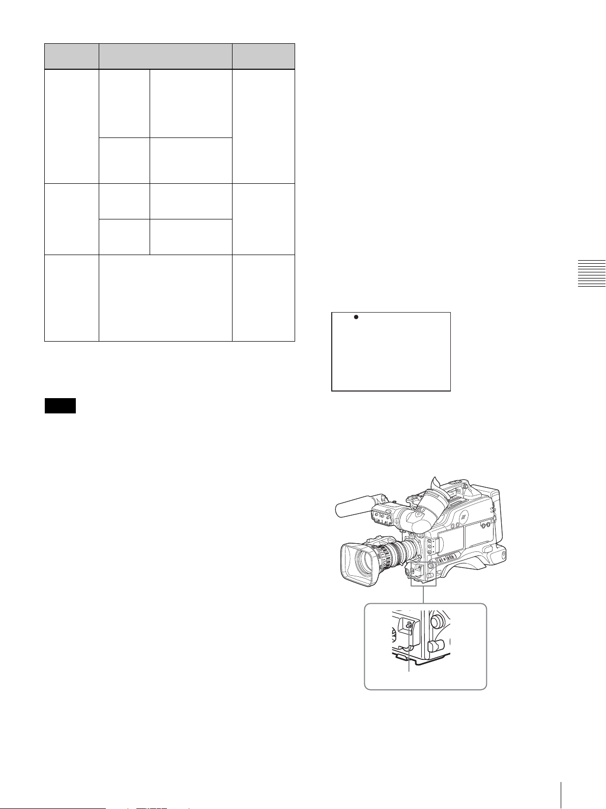
Shutter
mode
ECS
(Extended
Clear
Scan)
3)
SLS
(Slow
Speed
Shutter)
EVS
(Enhanced
Ver t ical
definition
System)
1) Only for the DSR-450WS/450WSP
2) Only for the DSR-450WS
3) The SLS mode can only be selected when the CCD scan mode (page 108)
is set to I (interlace scan) (DSR-450WS/450WSP only).
Shutter speed Application
DSR-400/
450WS
DSR400P/
450WSP
DSR450WS
DSR450WSP
Shutter speed currently
selected in the Standard or
ECS mode
Scan Mode: I
60.0 to 6000 Hz
Scan Mode: PsF
30.0 to 7000 Hz
Scan Mode: 24P
24.0 to 5000 Hz
Scan Mode: I
50.0 to 6000 Hz
Scan Mode: PsF
25.0 to 6000 Hz
1 to 8, 16 frames
(1/30 to 1/4, 1/2
sec.)
1 to 8, 16 frames
(1/25 to 1/3, 2/3
sec.)
For obtaining
images with
no horizontal
bands of
2)
noise when
shooting
subjects such
as monitor
screens.
For shooting
subjects in
low level
lighting
conditions.
Improved
vertical
resolution.
However, the
sensitivity
and dynamic
range are
reduced.
To select the shutter mode and shutter
speed
Use the SHUTTER switch to select a shutter mode or a
standard-mode shutter speed. To set the shutter speed in
ECS or SLS mode, with the SHUTTER switch set to ON
and the ECS or SLS mode selected, use the MENU knob
for adjustment.
You can use the SHT ENABLE page of the OPERATION
menu to narrow the range of choice in advance, or to select
in advance whether or not you use ECS/SLS mode.
To set the shutter mode and standard mode
shutter speed
Once the shutter speed is selected, it is retained even when
the camcorder is turned off.
1
Set VF DISP MODE to 2 or 3 on the VF DISP 1 page
of the OPERATION menu.
For details on menu operations, see “Basic menu
operations” on page 93.
?05 VF DISP 1 TOP
VF DISP : ON
VF DISP MODE : 1
DISP EXTENDER : ON
DISP WHITE : ON
DISP GAIN : ON
DISP SHUTTER : ON
DISP AUDIO : ON
DISP TAPE : ON
DISP IRIS : ON
Chapter 4 Recording and Playback
Notes
• Whatever the operating mode of the electronic shutter,
the sensitivity of the CCD decreases with increasing
shutter speed.
• When the automatic iris is used, the iris opens wider as
the shutter speed increases, thus reducing the depth of
field.
• Under artificial light, particularly fluorescent or mercury
lamps, the light intensity may appear to be constant, but
the red, green, and blue intensities are actually changing
in synchronization with the frequency of the power
supply causing flicker. Using an electronic shutter under
such lighting could make the flicker even worse. Color
flicker is particularly likely to happen when the power
supply frequency is 60 Hz. However, if the power
frequency is 50 Hz, setting the shutter speed to
1/100 can
reduce this flicker.
• When a bright object is shot in EVS or ECS mode in
such a manner that it fills the screen, the upper edge of
the picture may have poor quality because of an inherent
characteristic of CCDs. Before using EVS or ECS mode,
check the shooting conditions.
You can turn on or off the EVS mode on the SW STATUS
page of the PAINT menu.
2
Flick the MENU switch to OFF.
The menu disappears.
3
Push the SHUTTER switch from ON to SELECT.
SHUTTER switch
The current shutter setting indication appears for about
3 seconds in the setting change and adjustment
progress message display area of the viewfinder
screen.
Examples: “: SS: 1/250”, “: SLS: 1/30: 1FRAME”,
“: ECS: 60.0 Hz”
Recording
53
Page 54
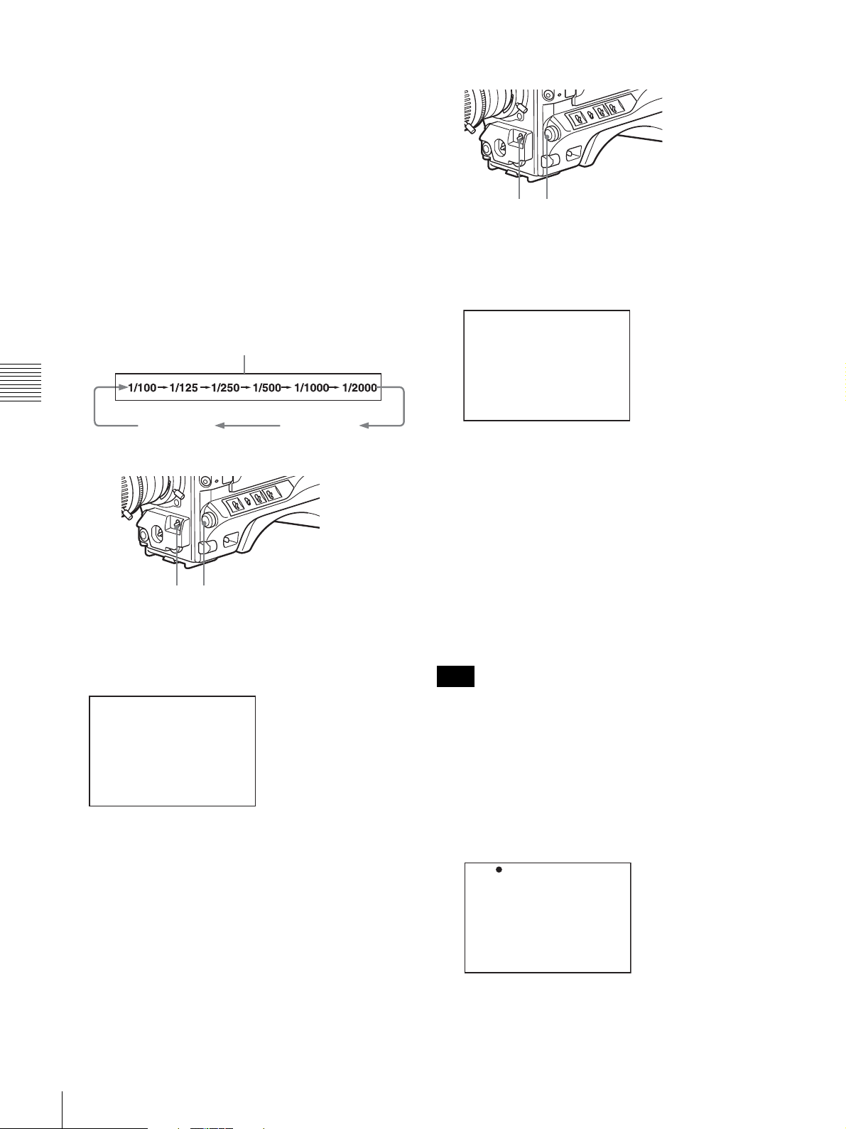
4
Before the shutter setting indication in step 3
disappears, push the SHUTTER switch down to
SELECT again. Repeat this until the desired mode or
speed appears.
The settings of mode and speed preselected on the
SHT ENABLE page of the OPERATION menu
displayed. Note that all modes and all standard-mode
speeds listed in the table on
using the SHT ENABLE page of the OPERATION
menu. By factory default, all available shutter modes
and shutter speeds are displayed in the sequence
shown in the following figure. (You can use the SHT
ENABLE page of the OPERATION menu to make a
setting so that only the desired (or most frequently
used) modes and speeds are displayed.)
Example of standard mode (when the scan mode is set to I)
page 52 are preselected
To set the shutter speed in SLS mode
2
1
1
Follow steps in “To set the shutter mode and standard
mode shutter speed” on page 53 to set the shutter
speed mode to SLS.
Chapter 4 Recording and Playback
SLS mode
To set the shutter speed in ECS mode
2
1
1
Follow steps in “To set the shutter mode and standard
mode shutter speed” on page 53 to set the shutter
speed mode to ECS.
ECS:60.00Hz
ECS mode
SLS: 1/30 : 1FRAME
2
Turn the MENU knob until the desired number of
frames appears.
The number of frames can be set to values in the range
1 to 8, and 16 (1 frame nearly equals to
To change the range of shutter mode and speed
settings
You can reduce the time required to select the shutter mode
and speed by narrowing the choice of settings in advance.
This can be done by using the SHT ENABLE page of the
OPERATION menu.
Note
The settings selected on the SHT ENABLE page of the
OPERATION menu become invalid when the RM-B150
Remote Control Unit is connected to the camcorder.
1
Display the SHT ENABLE page of the OPERATION
menu.
1/30 second).
2
Turn the MENU knob until the desired frequency
appears.
The selectable frequency range varies depending on
the scan mode. See the table on
modes” on page 52.
When the RM-B150 Remote Control Unit is
connected
You can set the shutter speed of ECS with the rotary
encoder of the RM-B150.
54
Recording
“About the shutter
For details on menu operations, see “Basic menu
operations” on page 93.
? 16 SHT ENABLE TOP
SHUTTER SLS : ON
SHUTTER ECS : ON
SHUTTER 1/100 : ON
SHUTTER 1/125 : ON
SHUTTER 1/250 : ON
SHUTTER 1/500 : ON
SHUTTER 1/1000 : ON
SHUTTER 1/2000 : ON
2
Press the MENU knob. Then turn the MENU knob to
move b to the shutter mode or shutter speed you want,
then press the MENU knob again.
b changes to z, and z changes to ?.
Page 55
3
Turn the MENU knob until ON appears, then press the
MENU knob.
Adjusting the iris
z changes to b, ? changes to z, and the selection is
set.
To set another mode or speed, return to step 2.
Note that only the mode and the shutter speeds set to
ON can be selected with the SHUTTER switch.
To set the automatic iris
The reference value for automatic iris adjustment can be
changed to aid the shooting of clear pictures of back-lit
subjects, or to prevent blown-out highlights. The reference
value for the lens iris can be set within the following range
with respect to the standard value.
• 0.5: about 0.5 stop further open
• 1: about 1 stop further open
• – 0.5: about 0.5 stop further closed
• –1: about 1 stop further closed
Also you can set the area where light detection occurs.
To change the reference value
1
Set IRIS OVERRIDE to ON on the AUTO IRIS page
of the OPERATION menu.
For details on menu operations, see “Basic menu
operations” on page 93.
? 11 AUTO IRIS TOP
IRIS OVERRIDE : ON
IRIS SPEED : ON
CLIP HIGH LIGHT : ON
IRIS WINDOW : 1
IRIS WINDOW IND : OFF
IRIS VAR WIDTH : 1687
IRIS VAR HEIGHT : 6007
IRIS VAR H POS : 0
IRIS VAR V POS : 0
Chapter 4 Recording and Playback
2
Flick the MENU switch to OFF.
The AUTO IRIS page disappears from the viewfinder
screen.
3
Turn the MENU knob to change the reference value as
below.
Note
When setting the shutter speed while the shutter mode
is set to ECS or SLS, the setting of shutter speed takes
priority
(page 53). To change the reference value,
make sure the camcorder is not in a process of setting
the shutter speed.
To open the iris by 0.5 stop
Turn the MENU knob counterclockwise as seen from
the front of the camcorder. One bar (s) appears in the
upper part to the left of the F number in the iris
indication.
To open the iris by 1 stop
Turn the MENU knob further counterclockwise as
seen from the front of the camcorder. Two bars (ss)
Recording
55
Page 56
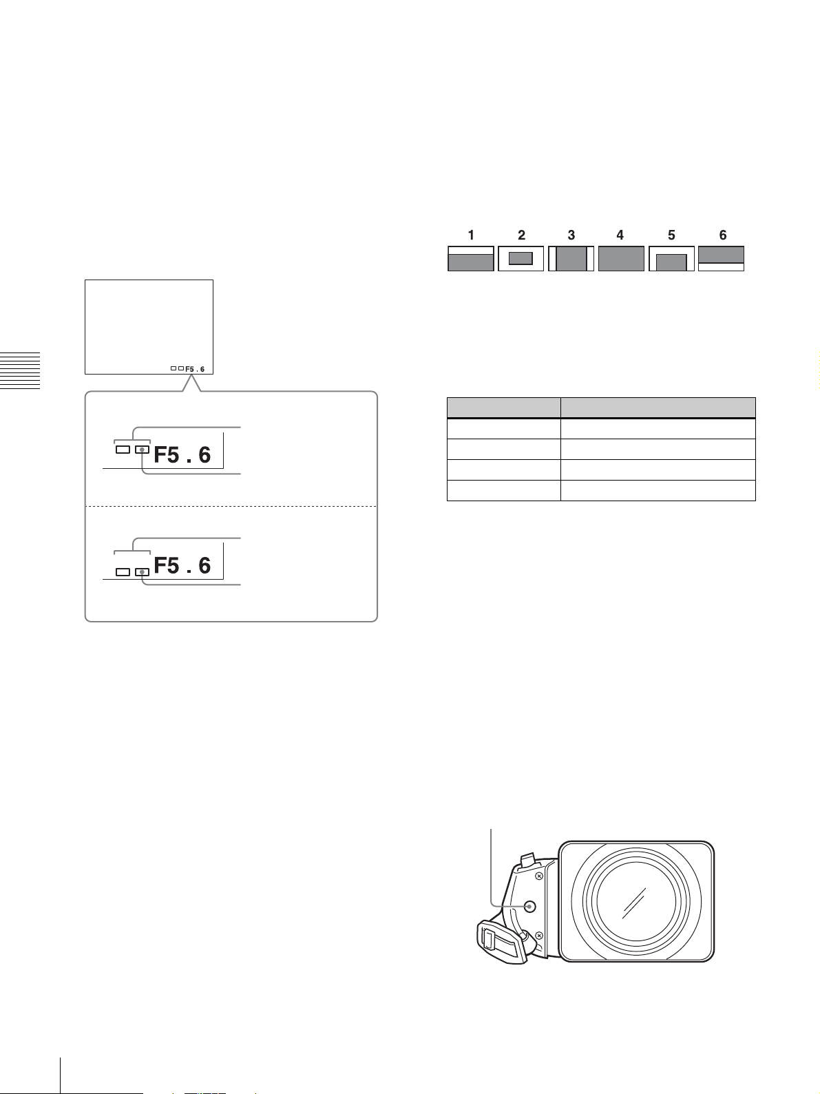
appear in the upper part to the left of the F number in
the iris indication.
2
Turn the MENU knob to move b to IRIS WINDOW,
and then press the MENU knob.
To stop down the iris by 0.5 stop
b changes to z and z changes to ?.
Turn the MENU knob clockwise as seen from the front
3
of the camcorder. One bar (s) appears in the lower
part to the left of the F number in the iris indication.
To stop down the iris by 1 stop
Turn the MENU knob further clockwise as seen from
Turn the MENU knob to select the desired automatic
iris window, and then press the MENU knob.
The shaded parts below indicate the area where light
detection occurs.
the front of the camcorder. Two bars (ss) appear in
the lower part to the left of the F number in the iris
indication.
z changes to b, ? changes to z, and the selection is
set.
If you select VAR, the following items become
effective and you can set the window of the desired
Chapter 4 Recording and Playback
Opening the lens iris
Iris opened by 1 stop
(two bars)
Iris opened by 0.5 stop
(one bar)
size. Set each item to the desired size.
Item Setting
IRIS VAR WIDTH Width of the window
IRIS VAR HEIGHT Height of the window
IRIS VAR H POS Horizontal position of the window
IRIS VAR V POS Vertical position of the window
Stopping down the lens iris
Iris stopped down by 1
stop (two bars)
Iris stopped down by 0.5
stop (one bar)
Not turning the MENU knob for a few seconds sets the
reference value. The changed reference value is
retained until the power of the camcorder is turned off.
Even if the reference value is changed, it reverts to the
standard value every time the power is turned on.
When the RM-B150 Remote Control Unit is
connected
The IRIS control knob of the RM-B150 can be used for
lens iris setting. In this case, the bar display (s) does not
appear.
To select the automatic iris window
1
Set IRIS WINDOW IND to ON on the AUTO IRIS
page of the OPERATION menu.
For details on menu operations, see “Basic menu
operations” on page 93.
To counter problems with very bright highlights
If the subject is too bright, the iris may close too much,
leaving the overall image dark, or the highlights may be
blown out. In such cases, setting the highlight clip function
on reduces the luminance range, avoiding problems from
the automatic iris correction.
In the AUTO IRIS page of the USER menu, set the CLIP
HIGH LIGHT item to ON.
To adjust the iris sensitivity
When you use the VCL-917BY lens, you usually need not
adjust the iris sensitivity because lenses are equipped with
iris sensitivity adjustment function.
In auto iris mode, if hunting or response delay happens,
adjust the iris sensitivity using the iris sensitivity trimmer.
Iris sensitivity trimmer (S or IRIS GAIN is indicated.)
IRIS
GAIN
56
The currently selected automatic iris window is
displayed on the viewfinder.
Set to OFF if the automatic iris window does not need
to be always displayed.
Recording
Page 57
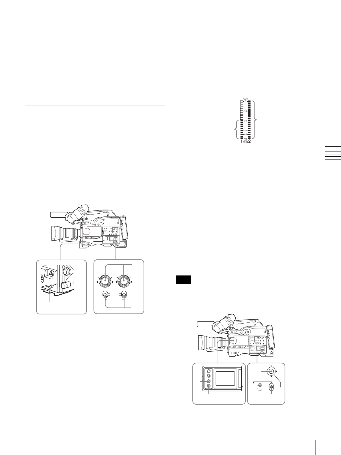
You can see the iris sensitivity trimmer when removing the
gum cap on the front of the lens driving unit. Use a miniscrewdriver to turn the trimmer. If you turn it clockwise,
the sensitivity increases, and if you turn it
counterclockwise, the sensitivity decreases.
It is recommended that you confirm the iris sensitivity
after replacing the lens.
For more information, refer to the operating instructions
for the lens (or consult the lens maker).
Adjusting the audio level
Setting the AUDIO SELECT (CH-1/CH-2) switches to
AUTO automatically adjusts the input levels of the audio
signal to be recorded in audio channels 1 and 2.
To manually adjust the levels of the audio
inputs from the AUDIO IN CH-1/CH-2
connectors
Proceed as follows to adjust the levels of the audio inputs
from the AUDIO IN CH-1/CH-2 connectors, which are to
be recorded in audio channels 1 and 2.
The input level value of the audio channel 1 is the
value of the AUDIO LEVEL CH-1 control on the side
multiplied by the value of the AUDIO LEVEL control
on the front.
The input level value of the audio channel 2 is the
value of the AUDIO LEVEL CH-2 control.
When the top bar (0 dB) turns on, the audio level is too
high. There is no problem if the second bar from the
top turns on.
All bars turn on.
These bars turn on.
Normal input level
Excessive input level
To adjust manually the level of audio channel 1
without using the AUDIO LEVEL control on the
front of the camcorder
Set F AUDIO VOL to DISABLE on the AUDIO page of
the MAINTENANCE menu.
The setting of the AUDIO LEVEL control on the front of
the camcorder is disabled.
Chapter 4 Recording and Playback
AUDIO LEVEL
AUTO
MANUAL
AUDIO SELECT
3
1
Select the audio channel that you want to record in.
3
2
For details, see “Selection of the recording audio
input” on page 37.
2
Set the AUDIO SELECT (CH-1/CH-2) switch(es)
corresponding to the audio channel(s) selected in step
1 to MANUAL.
3
With the AUDIO LEVEL control on the side of the
camcorder and the AUDIO LEVEL control on the
front of the camcorder, adjust so that the audio level
meter shows up to –20 dB for a normal input volume.
Setting the time data
To set the time code
The time code setting range is from 00:00:00:00 to
23:59:59:29 (DSR-400/450WS) or 23:59:59:24 (DSR400P/450WSP) (hours: minutes: seconds: frames).
Note
When the scan mode is 24P, see “Setting the CCD scan
mode (DSR-450WS/450WSP only)” on page 107 (DSR-
450WS only).
5
2
1
PRESET
REGEN
CLOCK
3
F-RUN
SET
R-RUN
4,6
1
Press the DISP SEL button of the LCD monitor to
display the STATUS screen.
Recording
57
Page 58
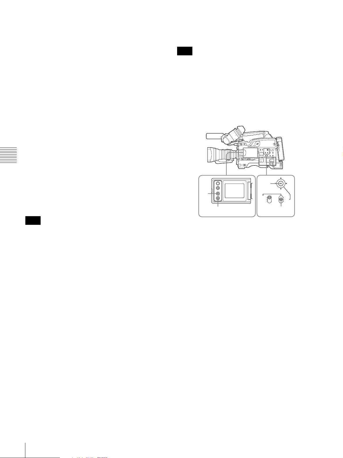
2
Press the DISPLAY button of the LCD monitor to
display TC on the counter display section.
3
Set the PRESET/REGEN/CLOCK switch to PRESET.
For details, see “Setting the date/time of the internal
clock” on page 105.
Note
4
Set the F-RUN/SET/R-RUN switch to SET.
The first (left-most) digit of time code flashes.
5
Use the arrow key to set the time code value including
the last (right-most) digit of the time code.
To reset the time code value to 00:00:00:00, press the
RESET button of the LCD monitor.
6
Set the F-RUN/SET/R-RUN switch to the desired
operating mode for the time code generator.
F-RUN: Free run. The time code generator keeps
running.
Chapter 4 Recording and Playback
R-RUN: Recording run. The time code generator runs
only while recording.
To set the DF (drop frame)/NDF (non-drop frame)
mode
You can select the drop frame (DF) mode or non-drop
frame (NDF) mode on the FUNCTION 1 page of the
OPERATION menu.
Note
When the scan mode is 24P, see “Setting the CCD scan
mode (DSR-450WS/450WSP only)” on page 107 (DSR-
450WS only).
To make the time code consecutive
When the F-RUN/SET/R-RUN switch is set to R-RUN,
recording a number of scenes on the tape normally
produces consecutive time code. However, once you
remove the cassette and record on another cassette, the
time code will no longer be contiguous even when you use
again the original cassette for recording.
In this case, to make the time code consecutive, proceed as
follows.
1
Set the PRESET/REGEN/CLOCK switch to REGEN.
2
Use the EDIT SEARCH +FWD/–REV button to select
the point where the recording should be start again.
This reads the previous recording and synchronizes the
internal time code generator, thus allowing the new
time code to be recorded consecutively.
To save the actual time in the time code
Setting the PRESET/REGEN/CLOCK switch to CLOCK
saves the actual time in the time code. When it is necessary
to set the actual time, use the TIME/DATE page of the
DIAGNOSIS menu.
When the scan mode is 24P, see “Setting the CCD scan
mode (DSR-450WS/450WSP only)” on page 107 (DSR450WS only).
To set the user bits
By setting the user bits (up to 8 hexadecimal digits), you
can record user information such as the date, time, or scene
number on the time code track.
4
2
1
1
Press the DISP SEL button of the LCD monitor to
display the STATUS screen.
2
Press the DISPLAY button on the LCD monitor to
display U-BIT in the counter display section.
3
Set the F-RUN/SET/R-RUN switch to SET.
The first (left-most) digit flashes.
4
Use the arrow key to set the time code value including
the last (right-most) digit of time code.
Hexadecimal digits A to F are displayed as A to F in
capital letters.
To reset the user bit data to 00 00 00 00, press the
RESET button of the LCD monitor.
5
Set the F-RUN/SET/R-RUN switch to the desired
operating mode for the time code generator.
F-RUN: Free run. The time code generator keeps
running.
R-RUN: Recording run. The time code generator runs
only while recording.
To synchronize the time code
You can synchronize the internal time code generator of
this camcorder with an external generator for the
regeneration of an external time code. You can also
PRESET
REGEN
CLOCK
F-RUN
SET
R-RUN
3,5
58
Recording
Page 59
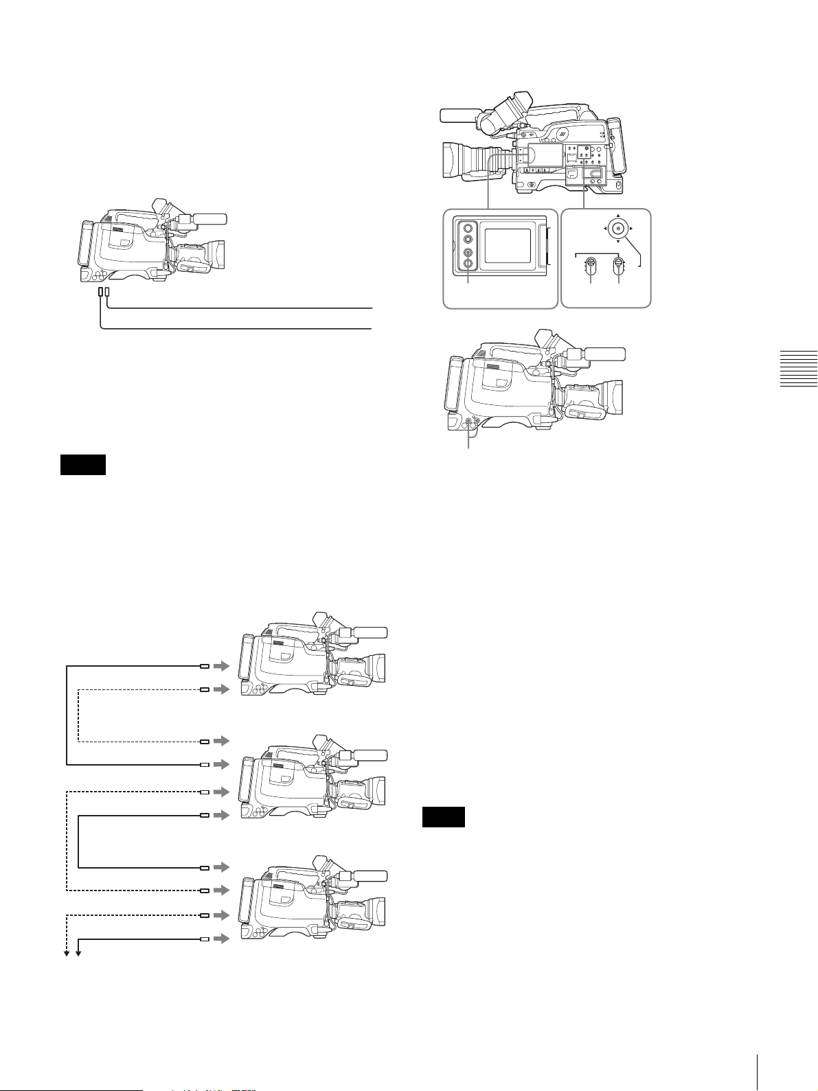
synchronize the time code generators of other camcorders/
VTRs with the internal generator of this camcorder.
Connections for time code synchronization
Connect both the reference video signal and the external
time code as illustrated below.
Example 1: Synchronizing with an external time code
To synchronize the time code
TC IN
GENLOCK IN *
* Set GENLOCK to ON on the GENLOCK page of the MAINTENANCE
menu, if GENLOCK is set to OFF.
External time code
Reference video signal
Example 2: Interconnecting a number of camcorders
and using one of them as the reference camcorder for
time code synchronization
Notes
• In the following configuration, wait until the reference
camcorder becomes stable (a state where a normal
picture appears on the viewfinder or the LCD monitor),
and then connect the other camcorders.
• When the scan mode is 24P, see “Setting the CCD scan
mode (DSR-450WS/450WSP only)” on page 107 (DSR450WS only).
MONITOR OUT
TC OUT
Reference camcorder
TC IN
GENLOCK IN *
TC OUT
3
PRESET
REGEN
CLOCK
F-RUN
SET
R-RUN
21
4
1
Set the PRESET/REGEN/CLOCK switch to PRESET.
2
Set the F-RUN/SET/R-RUN switch to F-RUN.
3
Press the DISPLAY button of the LCD monitor to
display TC on the counter display section.
4
Supply a time code signal and a reference video signal
complying with the SMPTE standard and in proper
phase relationship, to the TC IN connector and to the
GENLOCK IN connector, respectively.
This operation synchronizes the internal time code
generator with the external time code. After about 10
seconds, you can disconnect the external time code
without losing the synchronization. However, there
will be noise on the recorded image if you connect or
disconnect the time code signal during recording.
Chapter 4 Recording and Playback
MONITOR OUT
GENLOCK IN *
TC IN
TC OUT
MONITOR OUT
To another camcorder to be synchronized
* Set GENLOCK to ON on the GENLOCK page of the MAINTENANCE
menu, if GENLOCK is set to OFF.
Notes
• When you finish the above procedure, the internal time
code is immediately synchronized with the external time
code and the counter display will show the value of the
external time code. However, wait for a few seconds
until the sync generator stabilizes before recording.
• If the frequency of the reference video signal is not the
same as the frame frequency of the camcorder, the
camera cannot be correctly genlocked. In such a case, the
internal time code is not correctly synchronized with the
external time code.
Recording
59
Page 60

• When the internal time code generator is set to F-RUN
mode, the precision of the synchronization may be
reduced if you turn the POWER switch off and on or
keep the camcorder turned off for a long time.
• When the GENLOCK item is set to OFF on the
GENLOCK page of the MAINTENANCE menu, the
time code cannot be synchronized with the reference
video signal. In this case, set the GENLOCK item to ON.
About user bit settings during time code
synchronization
When the time code is synchronized, only the time data is
synchronized with the external time code value. Therefore,
the user bits can have their own settings for each
camcorder.
Shooting
conditions
The 3200K
preset white
balance makes
the picture
reddish.
Setting and effect
Setting: Change the setting of the preset
white balance on the PRESET WHT
page of the MAINTENANCE menu.
Effect: This prevents the picture from
reddening.
To correct skin detail
You can specify a color other than a skin tone to adjust the
color.
1
Set SKIN AREA IND to ON on the SKIN DETAIL
page of the PAINT menu.
To release the time code synchronization
First disconnect the external time code, then set the FRUN/SET/R-RUN switch to R-RUN.
To change the power supply from the battery
Chapter 4 Recording and Playback
pack to an external power supply during time
code synchronization
To maintain a continuous power supply, connect the
external power supply to the DC IN connector before
removing the battery pack. You may lose time code
synchronization if you remove the battery pack first.
Camera synchronization during time code
synchronization
During time code synchronization, the camera is
genlocked to the reference video signal input from the
GENLOCK IN connector.
Setting for special shooting cases
Depending on the shooting conditions, set the camcorder
appropriately referring below.
Shooting
conditions
The subject is
completely still
(Example: When
shooting
documents,
drawings, etc.).
When adjusting
for skin detail or
tone (Example:
When shooting
to hide skin
details)
Setting and effect
Setting: Set the EVS (Enhanced Vertical
definition System) function to ON on the
SW STATUS page of the PAINT menu.
Enabling the EVS function tends to
increase the occurrence of aliasing
problems (moiré patterns). Therefore,
normally leave the function disabled.
Effect: This enhances the vertical
resolution.
Setting: See “To correct skin detail” on
page 60.
Effect: This adjusts the skin detail or
tone to a designated active area.
For details on menu operations, see “Basic menu
operations” on page 93.
2
Set SKIN DETECT on the SKIN DETAIL page of the
PAINT menu.
This causes the area detect cursor to be shown in the
viewfinder.
3
Place the area detect cursor on the target, then execute
SKIN DETECT.
This designates the correction area, which is indicated
by a zebra pattern.
4
Change the value of SKIN DTL WIDTH (0 to 359) on
the SKIN DETAIL page so that the zebra pattern may
be displayed in the target area.
Set the correction level beforehand on the SKIN
DETAIL LVL item on the SKIN DETAIL page.
5
When the setting is finished, set SKIN AREA IND to
OFF on the SKIN DETAIL page.
60
Recording
Page 61
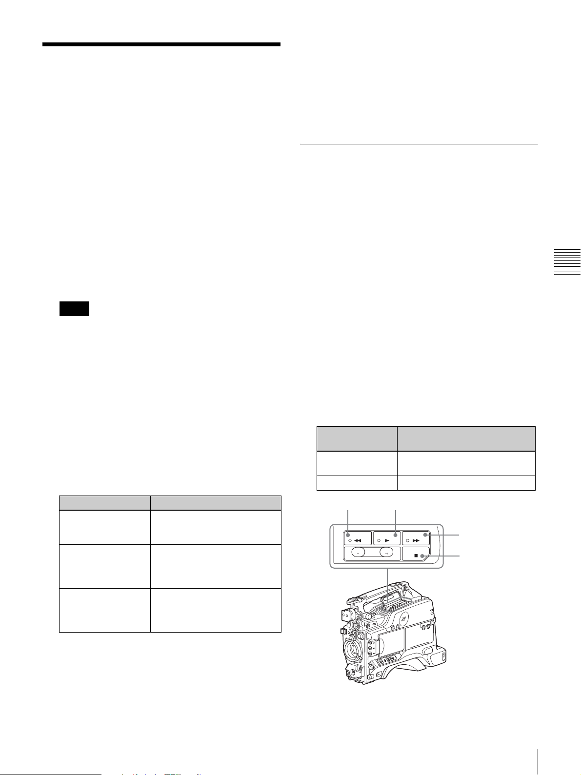
Back Space Editing
This section describes the steps for recording several
scenes continuously.
1
Follow steps in “Basic Procedure for Shooting” on
page 46 to begin recording.
To continue the time code that has been recorded on
the tape, set the F-RUN/SET/R-RUN switch to RRUN.
For details of time codes, see “Setting the time data”
on page 57.
2
When you have finished recording a scene, press the
REC button on the camcorder or the VTR button on
the lens.
This pauses the recording operation.
camcorder is in standby-off mode, it takes time for the
recording to start after pressing the REC button.
You can set the time out value for automatic switching to
standby-off mode from 1 minute, 3 minutes, or 5 minutes,
on the VTR MODE page of the MAINTENANCE menu
(page 84).
Starting back space editing at any
tape position
This section describes the steps for inserting a new scene
at any desired position on the tape.
The following steps can also be used to restart recording
after an interruption has occurred.
1
Insert the cassette containing the previous recording.
2
Perform steps 2 to 11 in “Basic Procedure for
Shooting” on page 46.
Chapter 4 Recording and Playback
Note
Do not do any of the following before the next scene
is shot as it will interrupt the recording (the
recording will not be continuous).
• Remove the cassette.
• Transport the tape (play, rewind, fast forward).
• Replace the battery when the camcorder is powered.
3
When you are ready to shoot the next scene, again
press the REC button on the camcorder or the VTR
button on the lens.
This restarts the recording operation.
4
Repeat steps 2 and 3 for each scene to be shot.
To Procedure
Restart an interrupted
recording (see step 2
above)
Check the recorded
contents
Stop recording Press the REC button on the
See next section “Starting back
space editing at any tape
position” on page 61.
See “Checking the recorded
contents immediately after
shooting — Recording Review”
on page 65.
camcorder or the VTR button on
the lens, then press the STOP
button.
To continue from the last time code of the previous
recording, set the PRESET/REGEN/CLOCK switch
to REGEN.
For details about time codes, see “Setting the time
data” on page 57.
3
Press the PLAY button.
The recorded contents are displayed on the viewfinder
screen.
Operation at
playback
Fast forward the
tape
Rewind the tape Press the REW button.
REW button
REW PLAY F FWD
EDIT
REV
SEARCH
Procedure
Press the F FWD button.
PLAY button
STOP
FWD
F FWD button
STOP button
If there is a long period before shooting
the next scene
Once put the camcorder into recording pause mode, it
waits a certain (user-definable) period of time and then
automatically switches to standby-off mode. When the
Back Space Editing
61
Page 62
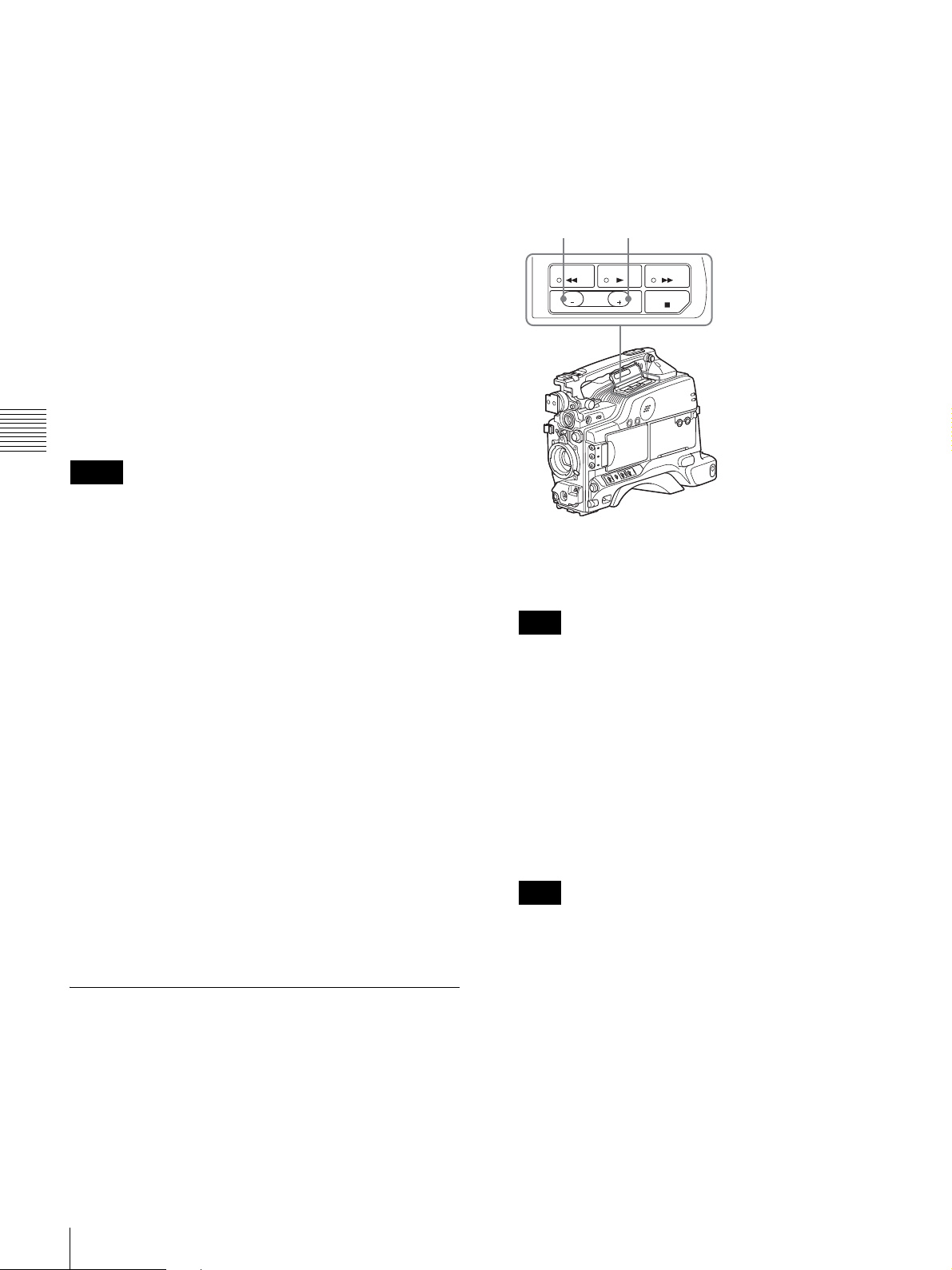
4
Press the STOP button when the tape reaches the
position where you want to start the new recording
(see the figure in step 3).
This stops playback.
5
Press the RET button on the lens.
This rewinds the tape slightly and runs it until the
continue point, then sets the camcorder to recording
pause state.
6
Press the REC button on the camcorder or the VTR
button on the lens.
This starts recording.
To carry out back space editing frame by frame,
specify the continue position using the edit search
function. For details, see the next section
edit search function while back space editing”.
Chapter 4 Recording and Playback
Notes
• When the scan mode is 24P, see “Setting the CCD scan
mode (DSR-450WS/450WSP only)” on page 107 (DSR-
450WS).
• If you set the POWER switch to off during recording or
when recording is paused, the camcorder automatically
goes through its shut-down sequence, then powers off.
When you next set the POWER switch to on, the
camcorder automatically finds the point at which
recording ended, and sets itself up so that you can carry
in with continuous recording. Note that this operation
takes several seconds: do not set the POWER switch to
off or replace the battery during this interval, as the
automatic recording continuity will be lost.
Note also that the recording continuity is lost in the
following cases.
- If the POWER switch is set to on and off repeatedly.
- If the camcorder is left powered off for several hours.
- If the camcorder is subject to severe vibration while
powered off.
- If for any other reason the automatic recording
continuity function is unable to operate correctly.
- If the lithium battery (CR2032) is exhausted, or if no
lithium battery has been fitted.
- If the recording format is changed.
“Using the
1
Insert the cassette containing the previous recording.
2
Perform steps 2 to 11 in “Basic Procedure for
Shooting” on page 46.
3
Press and hold either of the +FWD or –REV button of
the EDIT SEARCH +FWD/–REV buttons.
–REV button +FWD button
REW PLAY F FWD
EDIT
REV
SEARCH
The tape is moved in reverse or forward search mode
for as long as you hold down the button, and the image
is shown in the viewfinder.
Note
Do not shut off the power while using the edit search
function. The continue point may be lost.
4
Release the +FWD or –REV button when you find the
tape location where you want to continue shooting.
Recording is paused.
5
Press the REC button on the camcorder to the VTR
button on the lens.
Recording starts.
Note
When the scan mode is 24P, see “Setting the CCD
scan mode (DSR-450WS/450WSP only)” on page 107
(DSR-450WS only).
FWD
STOP
Using the edit search function while
back space editing
You can use the edit search function to find the desired
tape location when continuing to record from any other
location on the tape. Press and hold one of the EDIT
SEARCH +FWD/–REV buttons to activate the search
playback function for as long as you hold down it.
62
Back Space Editing
Page 63
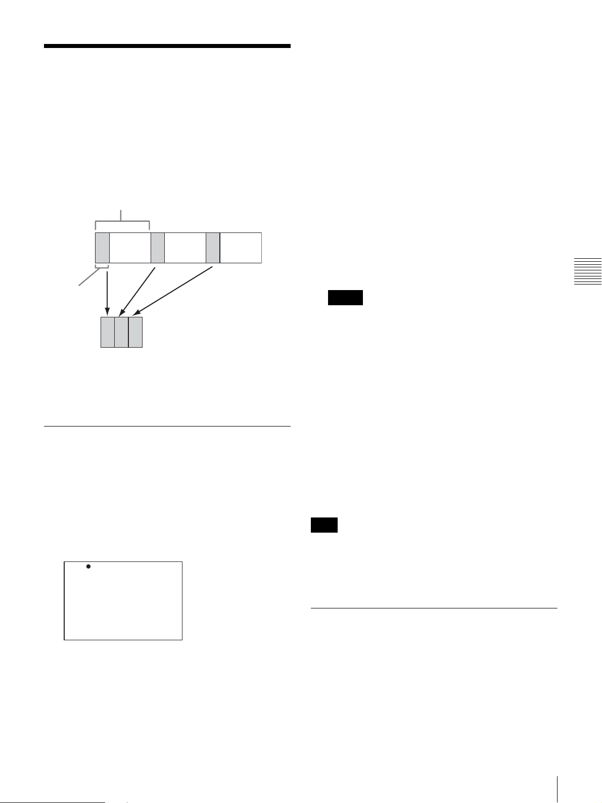
Time-Lapse Video
(Interval Rec)
Interval Rec mode is effective for shooting objects that
move very slowly. As shown in the following figure, you
need to set the recording time for one recording session
(REC TIME) and the total time consisting of one recording
session and the following interval (INTERVAL TIME).
Total time consisting of one recording session
and the following interval (INTERVAL TIME)
Recording
time for one
recording
session (REC
TIME)
A pre-lighting function is available. This function
automatically turns on the light before recording starts,
which allows you to record pictures under stable light and
color temperature conditions.
You can select either 30S, 1M, 5M, 10M, 30M, or 1H.
Here S means seconds (30S is 30 seconds), M means
minutes (5M is 5 minutes), and H means hours (1H is
one hour).
3
Set REC TIME (recording time for one recording
session) on the FUNCTION 1 page of the
OPERATION menu.
You can select either 0.5S, 1.0S, 1.5S, 2.0S, 5S, 10S,
30S, 1M, 5M, or 10M.
Here S means seconds (5S is 5 seconds) and M means
minutes (1M is one minute).
4
To turn on the light automatically before starting to
record, set PRE-LIGHTING (time to turn on the light
before starting to record) on the FUNCTION 1 page of
the OPERATION menu.
You can select either OFF, 2S, 5S, or 10S.
Notes
• Set the LIGHT switch on the camcorder to AUTO to
turn on the light before recording.
The light switch must also be set to ON. With these
settings, the light turns on and off automatically.
However, the light remains on continuously if the
off time is less than 5 seconds.
• When the LIGHT switch is set to MAN and the light
switch is set to ON, the light remains on
continuously.
Chapter 4 Recording and Playback
Making settings before shooting
To record in Interval Rec mode, you need to set the related
items beforehand as follows.
1
Set INTERVAL REC to ON on the FUNCTION 1
page of the OPERATION menu.
For details on menu operations, see “Basic menu
operations” on page 93.
? 03 FUNCTION1 TOP
ASSIGN SW <1> : ATW
ASSIGN SW <2> : OFF
ASSIGN SW <3> : OFF
ASSIGN SW <4> : OFF
DF/NDF : DF
INTERVAL REC : ON
REC TIME : 0.5S
INTERVAL TIME : 30S
PRE-LIGHTING : OFF
The camcorder is in Interval Rec mode. The TALLY
indicator (green) in the viewfinder flashes (one flash/
second) while the camcorder is in this mode.
2
Set INTERVAL TIME (total time consisting of one
recording session and the following interval) on the
FUNCTION 1 page of the OPERATION menu.
To end the menu operation, flick the MENU switch to
OFF. The menu disappears from the screen and the
message “INTERVAL” flashes along the bottom of
the screen.
You can check the setting of Interval Rec in the VTR
STATUS window
Note
(page 102).
The camcorder exits Interval Rec mode whenever it is
powered off. However, the settings of INTERVAL TIME,
REC TIME, etc. are maintained. You do not need to set
them again the next time you use Interval Rec mode.
Shooting and recording in Interval
Rec mode
1
After performing the basic procedures for shooting
and recording, following the instructions in
settings before shooting” on page 63, secure the
camcorder so that it will not move.
2
Press the REC button on the camcorder or the VTR
button on the lens.
“Making
Time-Lapse Video (Interval Rec)
63
Page 64
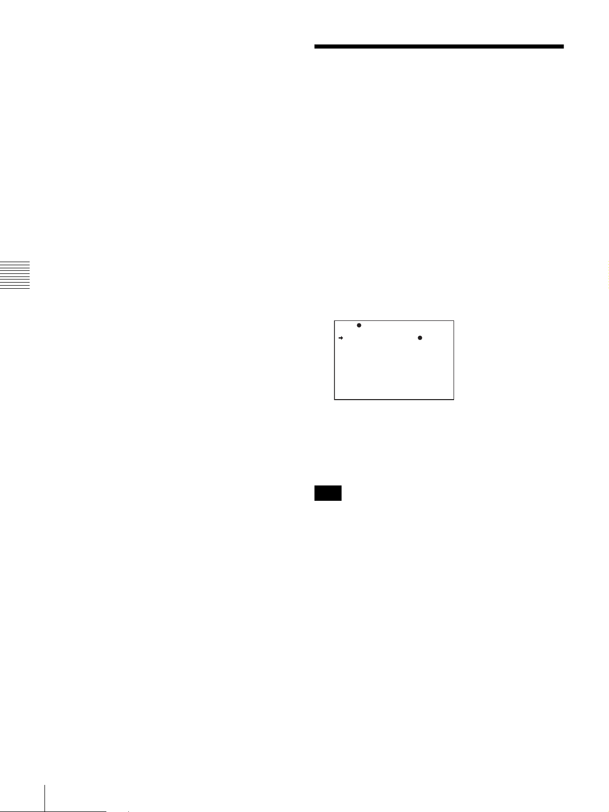
The camcorder starts recording in Interval Rec mode.
When you use the pre-lighting function, recording
starts after the light is switched on.
While recording in Interval Rec mode, the TALLY
indicator (green) in the viewfinder flashes (4 flashes/
second) and the message “INTERVAL” appears on
the viewfinder screen.
While recording, the REC indicator in the viewfinder
lights.
To interrupt interval recording
Press the REC button on the camcorder or the VTR button
on the lens. The camcorder operates as explained below.
When the button is pressed during interval
recording
Recording in Interval Rec mode stops. Press the REC or
VTR button again to start recording in Interval Rec mode
again.
Chapter 4 Recording and Playback
When the button is pressed during a pause of
interval recording
Recording in Interval Rec mode stops, and normal
recording starts. Press the REC or VTR button again to
interrupt recording. Press the REC or VTR button once
again to start recording in Interval Rec mode.
Recording Analog
Composite Signals (with
a CBK-SC01 InstalledDSR-450WS/450WSP
only)
Installing a CBK-SC01 Composite Input Board in the
camcorder enables you to record analog composite signals
from external equipment connected to the GENLOCK IN
connector.
1
Set REC VIDEO SOURCE to EXT on the SOURCE
SEL page of the OPERATION menu.
For details on menu operations, see “Basic menu
operations” on page 93.
19 SOURCE SEL TOP
REC VIDEO SOURCE: EXT
SETUP REMOVE :ON
To end auto interval recording
You can exit Interval Rec mode by setting the POWER
switch to OFF or setting INTERVAL REC to OFF on the
FUNCTION 1 page of the OPERATION menu.
Notes on Auto Interval Rec mode
Audio
Audio fade-in/fade-out functions are not carried out in
Interval Rec mode.
Playback control buttons
While recording in Interval Rec mode, you cannot use the
playback control buttons (EJECT, REW, F FWD, PLAY,
and STOP). To use these buttons, stop recording by
pressing the REC button on the camcorder or the VTR
button on the lens.
Menu operation
While recording in Interval Rec mode, you cannot change
the settings of INTERVAL TIME and REC TIME. To
change the settings, stop recording by pressing the REC
button on the camcorder or the VTR button on the lens.
2
Input analog composite signals to the GENLOCK IN
connector of the camcorder.
These signals are displayed on the viewfinder and the
LCD monitor, and can be recorded on the tape.
Note
Even when the GENLOCK item is set to OFF on the
GENLOCK page of the MAINTENANCE menu, the
camcorder is automatically synchronized with the external
reference video signal when the external video signal is
input to the GENLOCK IN connector in EXT mode. When
the setting is switched to CAM mode, or when no signals
are input even in EXT mode, the camcorder is reset to the
original setting.
To use setup remove (DSR-450WS only)
Setup remove is a function that removes a setup that has
been added to a video signal when recording. The factory
setting of setup remove is ON.
In order to set the setup remove function off, select OFF in
SETUP REMOVE on the SOURCE SEL page of the
OPERATION menu.
64
Recording Analog Composite Signals (with a CBK-SC01 Installed- DSR-450WS/450WSP only)
Page 65

Playing and Checking
Recorded Contents
By pressing the PLAY button, you can review any length
of recording on the viewfinder screen in black and white or
in color on the LCD monitor. There are two other ways to
review the recording.
• Recording review: You can view the last two to ten
seconds of the recording on the viewfinder screen in
black and white or in color on the LCD monitor.
• Playback in external color video monitor: You can see
the recording in color on a color video monitor without
the need for any external adaptor.
For details about the switches and controls used to select
the audio output signal and to adjust the audio level, see
“Location and Function of Parts” on page 9.
Checking the recorded contents
immediately after shooting —
Recording Review
With recording paused, press the RET button on the lens.
The tape is automatically rewound over the last
approximately 2 seconds of the recording (approximately
10 seconds maximum if you press and hold the RET
button), and then this last part of the recording is shown in
the viewfinder and on the LCD monitor. Use this function
to check whether recording went correctly.
By assigning the LENS RET function to the ASSIGN
switch, you can use the switch in the same way as the lens
RET button.
Checking the recording on the color
video monitor
Connect a color video monitor to the MONITOR OUT
connector or the VIDEO OUT connector of the camcorder.
By pressing the PLAY button, you can view the recorded
picture.
For details about how to connect a monitor, see
“Connecting a Monitor” on page 40.
Note
For the DSR-450WS/450WSP, only the picture displayed
through the camera is output to the CBK-SD01 SDI Output
Board. Playback pictures cannot be output even during
playback.
To use setup add (DSR-400/450WS only)
Setup add is a function that adds a setup to the playback
video signal. To activate this function, set SETUP ADD to
ON on the VTR MODE page of the MAINTENANCE
menu.
Notes
• The video image that connects the DVCAM format and
DV format is distorted during playback.
• The camcorder can play video and audio that is recorded
in DVCAM format or DV format (in SP mode).
• If two or more audio sampling frequencies are mixed on
one tape, the part where the video images are recorded in
different frequencies will be distorted.
Chapter 4 Recording and Playback
For details, see “Assigning functions to ASSIGN
switches” on page 106.
Notes
• During recording review, do not set the POWER switch
to off. The camcorder may not be able to find the
continue point.
• You cannot start recording until the recording review has
finished.
Playing and Checking Recorded Contents
65
Page 66
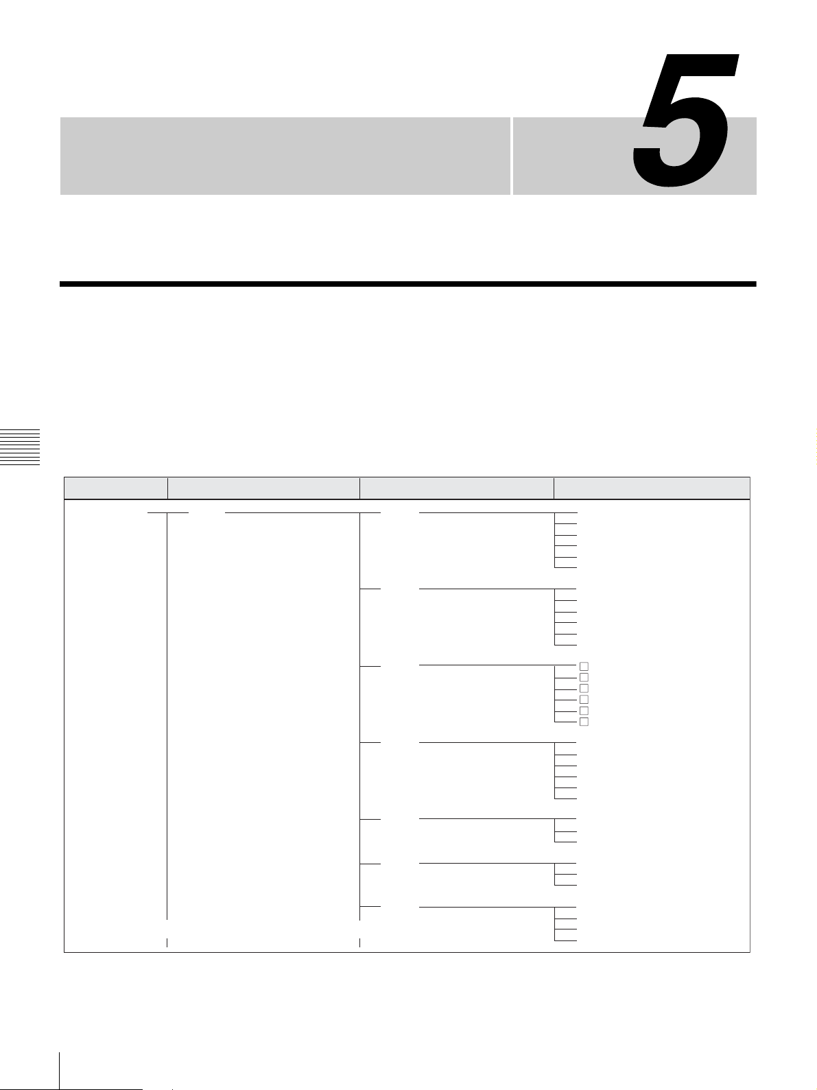
Menu Displays and
Detailed Settings
Menu Organization and Operation
The following shows the organization of menus in this
camcorder.
The USER menu consisting of items and pages registered
at the factory is used. The number in parenthesis is the
page number that setting is displayed on.
Chapter 5 Menu Displays and Detailed Settings
Menu selection
TOP MENU
(Continued)
1st hierarchy
USER
(Continued)
For details about USER MENU CUSTOMIZE, see
“Editing the USER menu” on page 95.
2nd hierarchy 3rd hierarchy
Page 1
Page 2
Page 3
Page 4
Page 5
Page 6
Page 7
Chapter
IRIS OVERRIDE
DETAIL LEVEL
MASTER BLACK
BLACK GAMMA
MASTER BLK GAMMA
COLOR TEMP <P>
SKIN DETAIL ALL
SKIN DETECT
SKIN AREA IND
SKIN DTL SELECT
SKIN DETAIL
SKIN DETAIL LVL
SCN 1
SCN 2
SCN 3
SCN 4
SCN 5
STANDARD
REC FORMAT
AU MODE
16:9/4:3 SELECT
SCAN MODE
REC VIDEO SOURCE
REAR BNC OUT SEL
GL H PHASE
GL SC PHASE
GL SC 0/180 SEL
MARKER
CENTER
SAFETY ZONE
ASSIGN SW <1>
ASSIGN SW <2>
ASSIGN SW <3>
ASSIGN SW <4>
(84)
(84)
(84)
(84)
(84)
(86)
(77)
(77)
(82)
1)
(82)
(82)
(84)
(86)
(88)
(88)
(78)
(81)
(82)
1)
(79)
(77)
(80)
(82)
(82)
(88)
(76)
(76)
(76)
(76)
(86)
(82)
(79)
3)
(81)
(79)
2)
(75)
1) Only for the DSR-450WS/450WSP
2) Only when a CBK-SC01 Composite Input Board is installed in the DSR450WS/450WSP
3) Only when a CBK-SD01 SDI Output Board is installed in the DSR450WS/450WSP
66
Menu Organization and Operation
Page 67
Menu selection
1st hierarchy
2nd hierarchy 3rd hierarchy
USER MENU CUSTOMIZE
ALL
OPERATION
(Continued)
(Continued)
Page 8
OUTPUT
MONITOR OUT
FUNCTION 1
FUNCTION 2
VF DISP 1
VF DISP 2
MARKER 1
CLOCK ADJUST
(91)
HOUR
(91)
MIN
(91)
SEC
(91)
YEAR
MONTH
(91)
DAY
LCD BRIGHT <L>
LCD BRIGHT <H>
LCD COLOR
REAR BNC OUT SEL
MONI OUT VFDISP
MONI OUT MENU
MONI OUT TC
MONI OUT MARKER
MONI OUT ZEBRA
ASSIGN SW <1>
ASSIGN SW <2>
ASSIGN SW <3>
ASSIGN SW <4>
3)
DF/NDF
INTERVAL REC
REC TIME
INTERVAL TIME
PRE-LIGHTING
D5600
WIDE AWB
WHITE SWITCH <B>
SHOCKLESS WHITE
ATW SPEED
LOW LIGHT
LOW LIGHT LEVEL
VF BATT WARNING
VF DISP
VF DISP MODE
DISP EXTENDER
DISP FILTER
DISP WHITE
DISP GAIN
DISP SHUTTER
DISP AUDIO
DISP TAPE
DISP IRIS
DISP COLOR TEMP
DISP BATT REMAIN
DISP DC IN
DISP 16:9/4:3 ID
DISP VTR STATUS
DISP VTR TRIGGER
DISP TIME CODE
DISP REC FORMAT
MARKER
CENTER
SAFETY ZONE
SAFETY AREA
ASPECT
ASPECT SELECT
ASPECT MASK(4:3)
ASPECT MASK LVL
100%MARKER
(91)
(91)
1)
1)
1)
2)
Chapter 5 Menu Displays and Detailed Settings
1)
1)
1) Only for the DSR-450WS/450WSP
2) Only when a CBK-SD01 SDI Output Board is installed in the DSR450WS/450WSP
3) Only for the DSR-400/450WS
Menu Organization and Operation
67
Page 68
Menu selection
1st hierarchy
2nd hierarchy 3rd hierarchy
MARKER 2
USER BOX
USER BOX WIDTH
USER BOX HEIGHT
USER BOX H POS
USER BOX V POS
CENTER H POS
CENTER V POS
GAIN SW
VF SETTING
GAIN LOW
GAIN MID
GAIN HIGH
GAIN TURBO
TURBO SW IND
ZEBRA
ZEBRA SELECT
ZEBRA1 DET LEVEL
ZEBRA1 APT LEVEL
ZEBRA2 DET LEVEL
AUTO IRIS
VF DETAIL LEVEL
VF ASPECT
IRIS OVERRIDE
IRIS SPEED
1)
CLIP HIGH LIGHT
IRIS WINDOW
IRIS WINDOW IND
IRIS VAR WIDTH
IRIS VAR HEIGHT
IRIS VAR H POS
IRIS VAR V POS
Chapter 5 Menu Displays and Detailed Settings
SHOT ID
ID-1
ID-2
ID-3
ID-4
SHOT DISP
SHOT DATE
SHOT TIME
SHOT MODEL NAME
SHOT SERIAL NO
SET STATUS
OFFSET WHT
SHOT ID SEL
SHOT 16:9 ID
SHOT BLINK CHARA
STATUS CAMERA
STATUS VTR
OFFSET WHITE <A>
WARM-COOL <A>
1)
COLOR FINE <A>
OFFSET WHITE <B>
WARM-COOL <B>
COLOR FINE <B>
SHT ENABLE
SHUTTER SLS
SHUTTER ECS
SHUTTER 1/32
SHUTTER 1/33
SHUTTER 1/40
SHUTTER 1/48
SHUTTER 1/50
SHUTTER 1/60
SHUTTER 1/96
SHUTTER 1/100
SHUTTER 1/120
1)
2)
3)
4)
2)
3)
5)
2)
6)
4)
SHUTTER 1/125
SHUTTER 1/250
(Continued)
(Continued)
SHUTTER 1/500
SHUTTER 1/1000
SHUTTER 1/2000
1) Only for the DSR-450WS/450WSP
2) Only for 24P mode
3) Only for PsF (progressive scan) mode and a video output signal set to PAL
4) Only for PsF (progressive scan) mode and a video output signal set to
NTSC
5) Only for I (interlace scan) mode and a video output signal set to PAL, or
for PsF (progressive scan) mode and a video output signal set to NTSC
68
Menu Organization and Operation
6) Only for I (interlace scan) mode and a video output signal set to NTSC, or
for PsF (progressive scan) mode and a video output signal set to PAL
Page 69
Menu selection
1st hierarchy
2nd hierarchy
3rd hierarchy
(Continued)
PAINT
(Continued)
LENS FILE
FORMAT
SOURCE SEL
SW STATUS
WHITE
BLACK/FLARE
GAMMA
BLACK GAMMA
KNEE
DETAIL 1
LENS FILE SELECT
F.ID
16:9/4:3 SELECT
WIDE ID
SCAN MODE
24P PULLDWN MODE
DF/NDF
1)
REC VIDEO SOURCE
SETUP REMOVE
2)
2)
2)
3)
3)
3)
GAMMA
CHROMA
MATRIX
KNEE
WHITE CLIP
DETAIL
APERTURE
FLARE
EVS
TEST SAW
COLOR TEMP <A>
COLOR FINE <A>
R GAIN <A>
B GAIN <A>
D5600K <A>
COLOR TEMP <B>
COLOR FINE <B>
R GAIN <B>
B GAIN <B>
D5600K <B>
Chapter 5 Menu Displays and Detailed Settings
MASTER BLACK
R BLACK
B BLACK
MASTER FLARE
R FLARE
G FLARE
B FLARE
FLARE
GAMMA
STEP GAMMA
MASTER GAMMA
R GAMMA
G GAMMA
B GAMMA
GAMMA SELECT
GAMMA SEL(STD)
GAMMA SEL(FILM)
2)
2)
BLACK GAMMA
BLK GAM RANGE
MASTER BLK GAMMA
R BLACK GAMMA
G BLACK GAMMA
B BLACK GAMMA
KNEE
KNEE POINT
KNEE SLOPE
KNEE SATURATION
KNEE SAT LEVEL
WHITE CLIP
WHITE CLIP LEVEL
DETAIL
APERTURE
DETAIL LEVEL
APERTURE LEVEL
DTL H/V RATIO
CRISPENING
LEVEL DEPEND
LEVEL DEPEND LVL
DETAIL FREQUENCY
1) Only when a CBK-SC01 Composite Input Board is installed in the DSR450WS/450WSP
2) Only for the DSR-450WS/450WSP
3) Only for the DSR-450WS
Menu Organization and Operation
69
Page 70
Menu selection
1st hierarchy
2nd hierarchy 3rd hierarchy
DETAIL 2
DETAIL 3
SKIN DETAIL
MTX LINEAR
Chapter 5 Menu Displays and Detailed Settings
MTX MULTI
V MODULATION
LOW KEY SAT
SCENE FILE
WHITE SHADING
(Continued)
MAINTENANCE
(Continued)
KNEE APERTURE
KNEE APT LVL
DETAIL COMB
CROSS COLOR
CROSS COLOR LVL
DETAIL LIMIT
DTL WHT LMT
DTL BLK LMT
DTL V-BLK LMT
FINE DTL
FINE DTL LVL
V DTL CREATION
H/V CONTROL MODE
SKIN DETAIL ALL
SKIN DETECT
SKIN AREA IND
SKIN DTL SELECT
SKIN DETAIL
SKIN DETAIL LVL
SKIN DTL SAT
SKIN DTL HUE
SKIN DTL WIDTH
MATRIX
MATRIX(USER)
MATRIX(PRESET)
MATRIX R-G
MATRIX R-B
MATRIX G-R
MATRIX G-B
MATRIX B-R
MATRIX B-G
MATRIX
MATRIX(MULTI)
MATRIX AREA IND
MATRIX COLOR DET
MTX(MULTI)AXIS
MTX(MULTI)HUE
MTX(MULTI)SAT
VMOD
MASTER VMOD
R VMOD
G VMOD
B VMOD
LOW KEY SAT
L.KEY SAT LEVEL
L.KEY SAT RANGE
Y BLACK GAMMA
Y BLK GAM LEVEL
Y BLK GAM RANGE
1
2
3
4
5
STANDARD
SCENE RECALL
SCENE STORE
F. ID
WHT SHAD CH SEL
R/G/B WHT H SAW
R/G/B WHT H PARA
R/G/B WHT V SAW
R/G/B WHT V PARA
WHITE SAW/PARA
70
Menu Organization and Operation
 Loading...