

Page 1
Digital
Videocassette
Player
3-869-574-12(1)
Operating Instructions
Before operating the unit, please read this manual
thoroughly and retain it for future reference.
DSR-1600A/1600AP
© 2005 Sony Corporation
Page 2
Owner’s Record
The model and serial numbers are located at the rear.
Record these numbers in the spaces provided below. Refer
to them whenever you call upon your Sony dealer
regarding this product.
Model No.
Serial No.
WARNING
To prevent fire or shock hazard, do not
expose the unit to rain or moisture.
To avoid electrical shock, do not open the
cabinet. Refer servicing to qualified
personnel only.
Important Safety Instructions
• Read these instructions.
• Keep these instructions.
• Heed all warnings.
• Follow all instructions.
• Do not use this apparatus near water.
• Clean only with dry cloth.
• Do not block any ventilation openings.
Install in accordance with the manufacturer’s
instructions.
• Do not install near any heat sources such as radiators,
heat registers, stoves, or other apparatus (including
amplifiers) that produce heat.
• Do not defeat the safety purpose of the polarized or
grounding-type plug. A polarized plug has two blades
with one wider than the other. A grounding-type plug
has two blades and a third grounding prong. The wide
blade or the third prong are provided for your safety. If
the provided plug does not fit into your outlet, consult an
electrician for replacement of the obsolete outlet.
• Protect the power cord from being walked on or pinched
particularly at plugs, convenience receptacles, and the
point where they exit from the apparatus.
• Only use attachments/accessories specified by the
manufacturer.
• Use only with the cart, stand, tripod,
bracket, or table specified by the
manufacturer, or sold with the apparatus.
When a cart is used, use caution when
moving the cart/apparatus combination to
avoid injury from tip-over.
• Unplug this apparatus during lightning
storms or when unused for long periods of
time.
• Refer all servicing to qualified service personnel.
Servicing is required when the apparatus has been
damaged in any way, such as power-supply cord or plug
is damaged, liquid has been spilled or objects have fallen
into the apparatus, the apparatus has been exposed to
rain or moisture, does not operate normally, or has been
dropped.
THIS APPARATUS MUST BE EARTHED.
CAUTION
The apparatus shall not be exposed to dripping or
splashing. No objects filled with liquids, such as vases,
shall be placed on the apparatus.
The unit is not disconnected from the AC power source
(mains) as long as it is connected to the wall outlet, even if
the unit itself has been turned off.
This symbol is intended to alert the user to
the presence of uninsulated “dangerous
voltage” within the product’s enclosure
that may be of sufficient magnitude to
constitute a risk of electric shock to
persons.
This symbol is intended to alert the user to
the presence of important operating and
maintenance (servicing) instructions in
the literature accompanying the
appliance.
WARNING: THIS WARNING IS APPLICABLE FOR
USA ONLY.
Using this unit at a voltage other than 120 V may require
the use of a different line cord or attachment plug, or both.
To reduce the risk of fire or electric shock, refer servicing
to qualified service personnel.
2
Page 3

For the customers in the USA (DSR-1600A only)
This equipment has been tested and found to comply with
the limits for a Class A digital device, pursuant to Part 15
of the FCC Rules. These limits are designed to provide
reasonable protection against harmful interference when
the equipment is operated in a commercial environment.
This equipment generates, uses, and can radiate radio
frequency energy and, if not installed and used in
accordance with the instruction manual, may cause
harmful interference to radio communications. Operation
of this equipment in a residential area is likely to cause
harmful interference in which case the user will be
required to correct the interference at his own expense.
You are cautioned that any changes or modifications not
expressly approved in this manual could void your
authority to operate this equipment.
All interface cables used to connect peripherals must be
shielded in order to comply with the limits for a digital
device pursuant to Subpart B of Part 15 of FCC Rules.
WARNING
Excessive sound pressure from earphones and headphones
can cause hearing loss.
In order to use this product safely, avoid prolonged
listening at excessive sound pressure levels.
For the customers in Taiwan only
For the customers in Europe (DSR-1600AP only)
This product with the CE marking complies with both the
EMC Directive and the Low Voltage Directive issued by
the Commission of the European Community.
Compliance with these directives implies conformity to
the following European standards:
• EN60065: Product Safety
• EN55103-1: Electromagnetic Interference(Emission)
• EN55103-2: Electromagnetic Susceptibility(Immunity)
This product is intended for use in the following
Electromagnetic Environments:
E1 (residential), E2 (commercial and light industrial), E3
(urban outdoors), E4 (controlled EMC environment, ex.
TV studio)
The manufacturer of this product is Sony Corporation, 17-1 Konan, Minato-ku, Tokyo, Japan.
The Authorized Representative for EMC and product
safety is Sony Deutschland GmbH, Hedelfinger Strasse
61, 70327 Stuttgart, Germany. For any service or
guarantee matters please refer to the addresses given in
separate service or guarantee documents.
3
Page 4

Table of Contents
Chapter 1 Overview
Chapter 2 Playback
Features................................................................................. 6
DVCAM Format ....................................................................... 6
A Wealth of Interfaces .............................................................. 7
Facilities for High-Efficiency Editing....................................... 7
Other Features ........................................................................... 7
Optional Accessories................................................................. 8
Location and Function of Parts........................................... 9
Front Panel ................................................................................ 9
Rear Panel ............................................................................... 15
Playback ..............................................................................19
Usable Cassettes...................................................................... 19
Inserting and Ejecting Cassettes ............................................. 21
Settings for Playback .............................................................. 22
Playback Procedure................................................................. 22
Repeat Playback—Automatic Cyclical Playback ................... 24
Setting Points A and B for Repeat Playback........................... 24
Cuing Up to Any Desired Position Set as Point A or B.......... 29
Chapter 3 Convenient Functions for Editing Operation
Displaying Time Data and Other Text Information .......... 30
Displaying Time Data and Operation Mode Indications ........ 30
High-Speed and Low-Speed Search—Quickly and
Accurately Determining Editing Points ..................... 33
Search Operations via External Equipment ............................ 33
Search Operations on This Unit .............................................. 33
Chapter 4 Menu Settings
Menu Organization ............................................................. 35
Menu Contents.................................................................... 38
Setup Menu ............................................................................. 38
Changing Menu Settings ...................................................45
Buttons Used to Change Settings............................................ 45
Changing the Settings of Basic Items ..................................... 45
Displaying Enhanced Items .................................................... 47
Changing the Settings of Enhanced Items .............................. 47
Table of Contents
4
Page 5

Returning Menu Settings to Their Factory Default Settings... 48
Chapter 5 Connections and Settings
Connections for a Digital Non-Linear Editing System .... 49
Connections for a Cut Editing System ............................. 51
Connections for an A/B Roll Editing System................... 52
Adjusting the Sync and Subcarrier Phases ..................... 57
Chapter 6 Maintenance and Troubleshooting
Maintenance........................................................................ 59
Condensation........................................................................... 59
Regular Checks ....................................................................... 59
Head Cleaning......................................................................... 61
Troubleshooting ................................................................. 62
Error Messages........................................................................ 63
Alarm Messages...................................................................... 63
Appendixes
Precautions .........................................................................65
Specifications ..................................................................... 66
Glossary .............................................................................. 69
Index .................................................................................... 71
Table of Contents
5
Page 6
Overview
Features
The DSR-1600A/1600AP is a 1/4-inch digital video
cassette player using the DVCAM digital recording
format. It achieves stable, superb picture quality by
digitally processing video signals separated into color
difference signals and luminance signals (component
method).
The unit is equipped with a variety of functions needed for
videocassette players used in professional digital video
editing systems.
The unit is also equipped with an i.LINK interface, thus
enabling simple connection with a nonlinear editing*
system supporting DV format.
Futhermore, the unit is equipped with a full-fledged analog
interface to support hybrid systems that combine
conventional analog equipment with digital equipment.
* Non-linear editing: This is an editing method that uses video and audio
signals digitally encoded and recorded on a hard disk as digital data. When
compared with conventional (linear) editing methods, non-linear editing
offers vastly improved efficiency in editing operations, for example, by
eliminating tape transport time.
The main features of the unit are described in the
following.
DVCAM Format
DVCAM is based on the consumer DV format, which uses
the 4:1:1 component digital format, and provides a
digital recording format for professional use.
High picture quality, high stability
Video signals are separated into color difference signals
and luminance signals, which are encoded and compressed
to one-fifth size before being recorded to ensure stable and
superb picture quality.
1
/4-inch
Chapter 1
Because the recording is digital, multi-generation dubbing
can be performed with virtually no deterioration of quality.
Wide track pitch
The recording track pitch is 15 µm, fully 50 percent wider
than the 10-µm track pitch of the DV format. Thanks to this
feature, the DVCAM format sufficiently meets the
reliability and precision requirements of professional
editing.
High-quality PCM digital audio
PCM recording makes for a wide dynamic range and a
high signal-to-noise ratio, thereby enhancing sound
quality.
There are two recording modes: 2-channel mode (48-kHz
sampling and 16-bit quantization), which offers sound
quality equivalent to the DAT (Digital Audio Tape)
format, or 4-channel mode (32-kHz sampling and 12-bit
quantization). Cassettes recorded in either mode can be
played back on this unit.
Playback compatibility with DV and
DVCPRO formats
A DV cassette recorded on a DV format VCR (excluding
the tapes recorded in LP mode) as well as a DVCPRO
(25M) format recorded cassette can be played back on this
unit.
Note
When playing back a tape recorded in DVCPRO (25M)
format, the i.LINK output (see “Digital interfaces” on
page 7) of this unit is subjected to muting. Furthermore, it
is not possible to play back the cue-audio track of the tape.
6
Features
Page 7

Support for three cassette sizes
There are two sizes of DVCAM cassette: standard and
mini. You can use either size with this unit.
The unit also accepts L and M sizes of DVCPRO cassette.
• When a cassette is inserted, the reel mechanism of the
unit automatically adjusts to the size of the inserted
cassette.
• The capacity of a standard cassette is 184 minutes of
playback, and that of a mini cassette is 40 minutes.
A Wealth of Interfaces
Digital interfaces
i.LINK (DV)*: The unit can output digital video and audio
signals in DV format.
* i.LINK and are trademarks and indicate that this product is in
agreement with IEEE1394-1995 specifications and their revisions.
SDI (serial digital interface)/AES/EBU (optional
DSBK-1601 SDI/AES/EBU Output Board): When
the unit is fitted with the optional DSBK-1601 board,
it can output D1 (component)-format digital video and
audio signals and also AES/EBU-format digital audio
signals.
Analog interfaces
The unit also comes with analog interfaces enabling it to be
connected to analog video and audio equipment.
Analog video: Output connectors for component,
composite, and S-video signals are provided.
Analog audio: Four output channels are provided.
Playback control using search dial
The search dial on the front panel of the unit allows you to
carry out playback operation in jog or shuttle mode
without requiring an external editing control unit or remote
control unit to be connected to the unit.
High-speed search function
You can carry out color picture searches during fast
forward and rewind at speeds up to 85 times normal speed.
When remote-controlling this unit in shuttle mode from an
editing control unit or a remote control unit, you can search
at any speed in the range 0 (still) to 60 times normal speed
in both directions. You can also search frame-by-frame in
jog mode.
At search speeds up to 10 times normal speed in both
directions, you can also hear playback audio.
Digital slow-motion playback
Using the frame memory function, the unit can show
noise-free slow-motion playback at speeds ranging from 0
1
to
/2 times normal speed in both directions.
Digital jog sound function
When searching at speeds in the range +1 to +1/30* or
1
−
/30 to −1 times normal speed, the digital jog sound
function is enabled. The audio signal is saved in temporary
memory, and replayed according to the search speed. This
allows searching on the sound track.
* The positive direction refers to forward movement of the tape, and the
negative direction to reverse movement.
Chapter 1 Overview
Facilities for High-Efficiency Editing
The unit provides an abundance of functions that enhance
editing efficiency and precision.
Internal time code reader
An internal time code reader enables time code compliant
with SMPTE (for DSR-1600A)/EBU (DSR-1600AP)
format to be played back. This allows editing to single
frame precision.
Outputting time code (LTC) to an external device is also
possible using the TIME CODE OUT connector.
The unit is also compatible with VITC.
Remote control
The unit can be operated by remote control from an editing
control unit that supports the RS-422A interface or from an
optional SIRCS*-compatible remote control unit such as
the DSRM-10.
* SIRCS (Sony Integrated Remote Control System): A command protocol
to remote control Sony professional videocassette recorders/players.
Video process control
For analog video output and SDI-format video output, you
can adjust the video output level, chroma signal output
level, setup level (for DSR-1600A), black level (for DSR1600AP), and chroma phase.
Other Features
Function to make a convenient
presentation tool of this unit
“Repeat playback” function
The unit can perform automatic cyclical playback between
two selected points on the tape.
“Power-on playback” function (in repeat
playback mode)
You can choose a menu setting so that powering on the
unit makes it immediately start playback.
Features
7
Page 8

Menu system for functionality and
operation settings
The unit provides a menu system to make its various
functions easier to use and set up its operation conditions.
Superimposition function
Time code values, operation mode indications, error
messages, and other text data can be superimposed and
Chapter 1 Overview
output in analog composite video signals.
Easy maintenance functions
Self-diagnostic/alarm function: This function
automatically detects setup and connection errors,
operation faults, and other problems. It also displays a
description of the problem, its cause, and the
recommended response on the video monitor screen or
time counter display.
Digital hours meter: The digital hours meter functions
include four kinds of tally operations for operating
hours, head drum usage hours, tape transport hours,
and tape threading/unthreading times. The tally results
can be viewed on the video monitor or the time counter
display.
Compatible with wide-screen aspect ratio
(16:9)
The unit can play back aspect ratio information. When
video accompanied by wide-screen aspect ratio
information is played back, the unit can output the video
signal also containing the aspect ratio information.
Rack mountable
When you use an optional rack mount kit, you can mount
this unit onto an EIA-standard 19-inch rack (height = 4
units).
Optional Accessories
DSBK-1601 SDI/AES/EBU Output Board
When installed in the unit, this optional board enables
digital video and audio signals in the D1 format and also
AES/EBU-format digital audio signals to be output from
the unit to digital Betacam VCRs or other equipment.
RMM-131/1 Rack Mount Kit
This kit can be used to mount the unit onto an EIAstandard 19-inch rack.
8
Features
Page 9
Location and Function of Parts
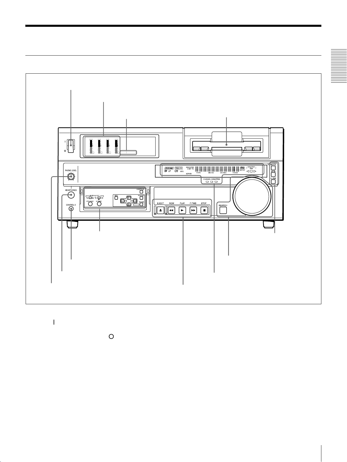
Front Panel
a POWER switch
POWER
OVER
dB
dB
dB
0
0
0
1
-12
-12
0
-20
-20
-1
-30
-30
-40
-40
-2
-60
-60
1
A Menu control panel (inside of
b Audio level meters
c PB FS display
OVER
OVER
OVER
dB
dB
dB
dB
dB
0
0
0
0
0
1
1
1
-12
-12
0
0
0
-20
-20
-1
-1
-1
-30
-30
-40
-40
-2
-2
-2
PB FS
-60
2
3
48k44.1k32k
-60
4
A B
MARK
the door) (see page 10)
Chapter 1 Overview
d Cassette compartment
E Remote control
setting section
(see page 14)
g CONTROL S connector
f HEADPHONES connector
e PHONE LEVEL control knob
a POWER switch
Press the “ ” side to power the unit on. When the unit is
powered on, the display windows in the front panel lights.
To power the unit off, press the “ ” side of the switch.
b Audio level meters
These show the audio levels of channels 1 to 4 during
playback.
c PB FS (playback audio sampling frequency)
display
Indicates the sampling frequency (48 kHz, 44.1 kHz or 32
kHz) at which audio is recorded on tape.
D Search control section
(see page 13)
C Display section (see page 12)
B Tape transport control section (see page 11)
d Cassette compartment
Accepts DVCAM, DV and DVCPRO (25M)
videocassettes.
For details of usable cassettes, see page 19.
e PHONE LEVEL control knob
Controls the volume of the headphones connected to the
HEADPHONES connector.
f HEADPHONES connector (stereo phone jack)
Connect stereo headphones for headphone monitoring
during playback.
The audio signal you want to monitor can be selected with
the MONITOR SELECT switches on the menu control
panel.
Location and Function of Parts
9
Page 10
g CONTROL S connector (stereo minijack)
Connect a SIRCS-compatible remote control unit such as
the DSRM-10.
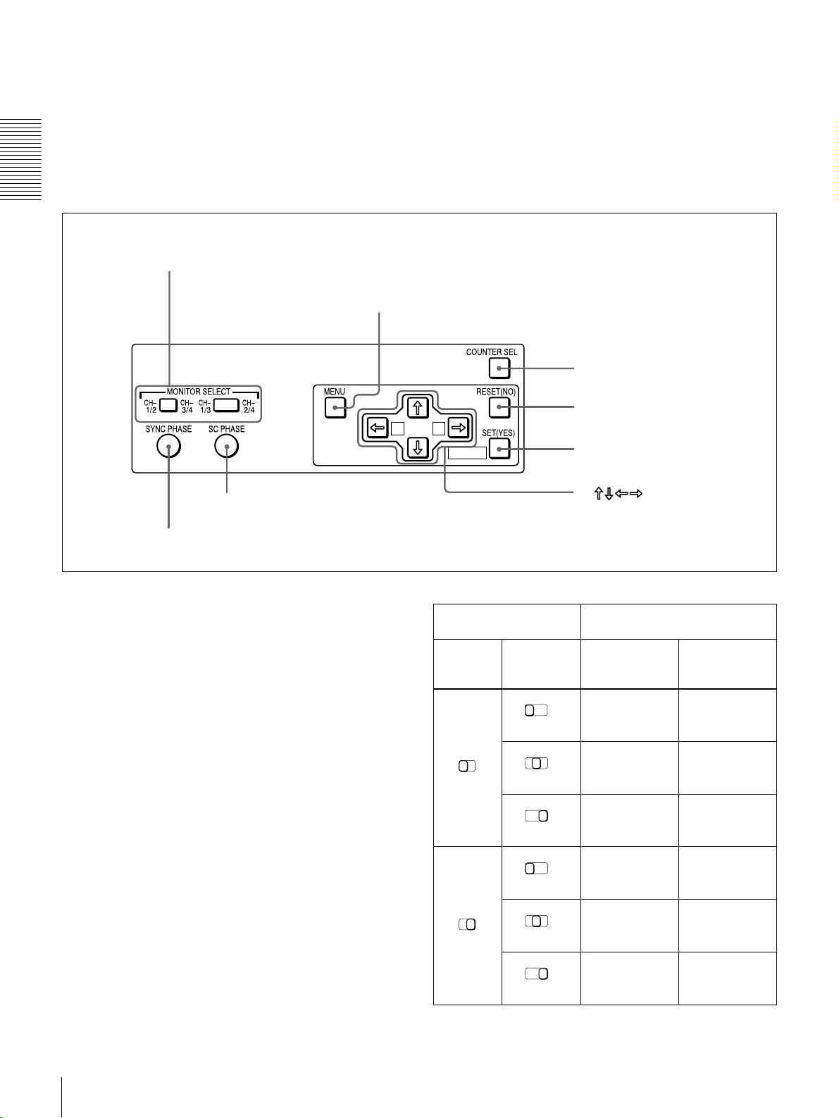
A Menu control panel
The menu control panel is located on the inside of the door
at the lower front of the unit. Pull the top of the door to
open it.
Chapter 1 Overview
a MONITOR SELECT switches
b MENU button
c COUNTER SEL button
MIX
A B
g SC PHASE control
h SYNC PHASE control
a MONITOR SELECT switches
Use these switches to select the channels for audio output
via the AUDIO MONITOR OUT connector on the rear
panel and the HEADPHONES connector on the front
panel.
Use the left switch to select the basic channel setting, then
use the right switch to select the output format (monaural,
stereo, or mix).
The following table lists the correspondence of left/right
switch settings and channel/output format selections.
d RESET (NO) button
MARK
e SET (YES) button
f buttons
Switch setting Selected channel and output
format
Left
switch
Right
switch
HEADPHONES
connector
AUDIO
MONITOR OUT
connector
CH1/3
MIX
CH-
1/2
CH-
CH-
1/3
3/4
MIX
CH-
1/3
MIX
Channel 1 only
CH2/4
(monaural)
Channels 1 and
CH-
2/4
2 (stereo)
Channel 2 only
CH-
2/4
(monaural)
Channel 1 only
(monaural)
Channels 1 and
2 (mix)
Channel 2 only
(monaural)
Location and Function of Parts
10
CH-
1/3
MIX
CH-
1/2
CH-
CH-
1/3
3/4
MIX
CH-
1/3
MIX
Channel 3 only
CH-
2/4
(monaural)
Channels 3 and
CH-
2/4
4 (stereo)
Channel 4 only
CH-
2/4
(monaural)
Channel 3 only
(monaural)
Channels 3 and
4 (mix)
Channel 4 only
(monaural)
Page 11
b MENU button
Press this button to display the menu on the monitor screen
and the time counter display. Press it again to return from
the menu display to the usual display.
On how to use the menu, see Chapter 4 “Menu Settings
(page 35).”
c COUNTER SEL (selection) button
Selects the type of time data to be shown in the time
counter display. Each press of this button cycles through
three indicator display options: COUNTER (CNT: count
value of the time counter), TC (time code), and U-BIT
(user bits).
• send a negative response to the prompts issued by the
unit.
e SET (YES) button
Press this button to:
• save new menu settings to the memory of the unit,
• confirm the start and end point settings for repeat
playback, or
• send a positive response to the prompts issued by the
unit.
f Arrow (
JjK k) buttons
Use these buttons to move around the menu items, and also
to specify and check the repeat playback section.
Chapter 1 Overview
Note
When the REMOTE button in the remote control setting
section is lit, the COUNTER SEL button does not operate.
In this case, make the time data selection via the remote
equipment that is connected to the REMOTE connector on
the rear panel.
d RESET (NO) button
Press this button to:
• reset menu settings,
• reset the time count (COUNTER) shown in the time
counter display to zero, or
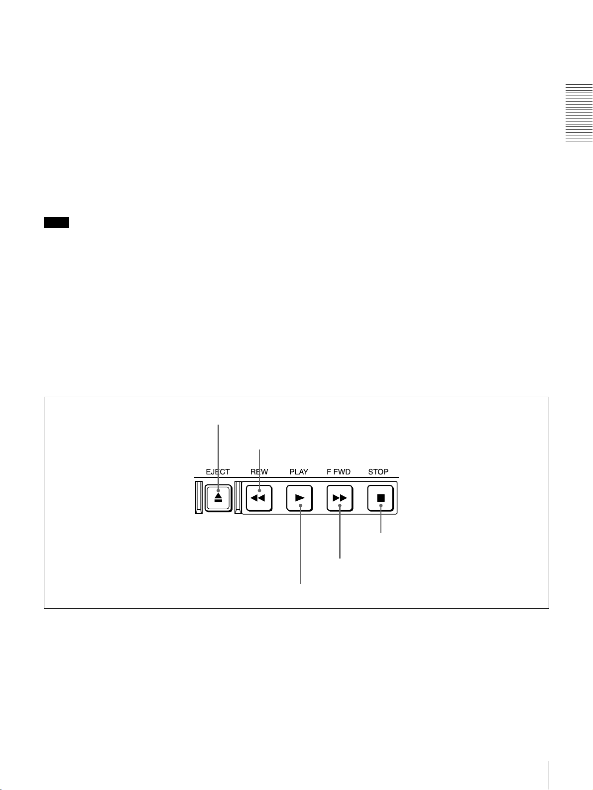
B Tape transport control section
a EJECT button
b REW button
g SC (subcarrier) PHASE control
Turn this control to accurately adjust the subcarrier phase
of the composite video output signal of the unit with
respect to the reference video signal. Use a cross-point
(Phillips) screwdriver to turn it.
h SYNC (synchronization) PHASE control
Turn this control to accurately adjust the synchronization
phase of the output video signal of the unit with respect to
the reference video signal. Use a cross-point (Phillips)
screwdriver to turn it.
a EJECT button
When you press this button, it lights and the cassette is
automatically ejected after a few seconds.
b REW (rewind) button
When you press this button, it lights and the tape starts
rewinding (maximum 85 times normal speed). You can
monitor the playback picture during the rewind.
e STOP button
d F FWD button
c PLAY button
c PLAY button
When you press this button, it lights and playback begins.
d F FWD (fast forward) button
When you press this button, it lights and the tape is fast
forwarded (maximum 85 times normal speed). You can
monitor the playback picture during the fast forward.
Location and Function of Parts
11
Page 12
e STOP button
Press this button to stop the current tape transport
operation.
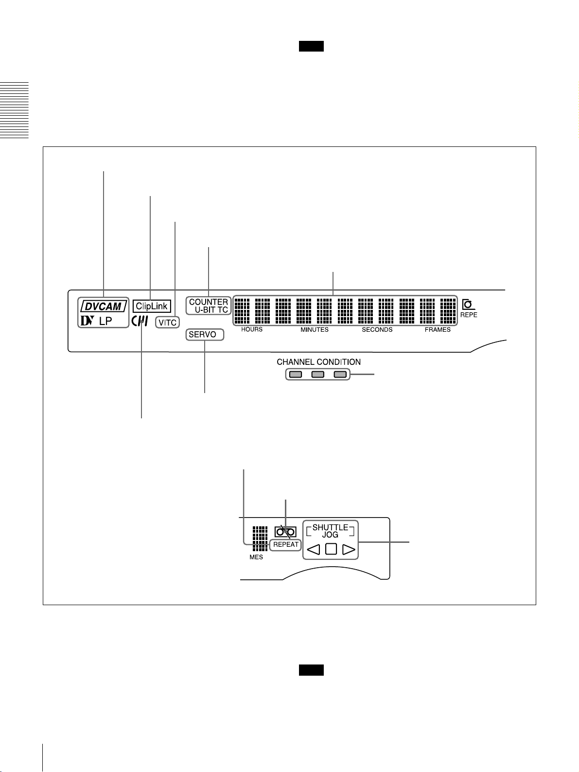
C Display section
Chapter 1 Overview
a Playback format indicators
b ClipLink indicator
c VITC indicator
Note
No tape transport control buttons other than the EJECT
and STOP buttons will work while the REMOTE button in
the remote control setting section is lit. This can be
changed with the LOCAL ENABLE menu item (see page
38).
d Time data type indicators
e Time counter display
g SERVO indicator
f Cassette memory indicator
i REPEAT indicator
a Playback format indicators
DVCAM: This lights when a tape recorded in DVCAM
format is played back.
DV: This lights when a tape recorded in consumer DV
format is played back.
LP: This lights when a tape recorded in LP mode is played
back.
h CHANNEL CONDITION indicators
j Tape end alarm indicator
k SHUTTLE/JOG indicators
When a tape recorded in DVCPRO (25M) format or any
other format than those mentioned above is played back,
none of the above indicators lights.
Note
A tape recorded in LP mode cannot be played back
correctly. When a tape recorded in LP mode is played
back, “DV LP” flashes and audio is muted.
Location and Function of Parts
12
Page 13
b ClipLink indicator
Lights when a cassette is loaded on which ClipLink log
data is stored in the cassette memory.
c VITC indicator
Lights when VITC is being read regardless of the data
shown in the time counter display.
mode using the search dial, the JOG indicator lights. When
the search dial is turned clockwise causing playback to
take place in the forward direction, the G indicator lights.
When the search dial is turned counterclockwise causing
playback to take place in the reverse direction, the g
indicator lights. When the tape is stopped, the s indicator
lights.
d Time data type indicators
One of the three indicators (COUNTER, U-BIT, and TC)
lights to indicate the type of time data currently shown in
the time counter display.
COUNTER: Count value of the time counter
U-BIT: User bit data
TC: SMPTE time code (for DSR-1600A) or EBU time
code (for DSR-1600AP)
e Time counter display
Indicates the count value of the time counter, time code,
VITC, or user bit data depending on the settings of the
COUNTER SEL button on the menu control panel and the
TC SELECT menu item (see page 41).
Also used to display error messages and setup menu data.
f Cassette memory indicator
Lights when a cassette provided with a memory chip
(“cassette memory”) is loaded.
g SERVO indicator
This indicator lights when the drum servo and capstan
servo are locked*.
* Servo lock: This refers to the synchronization of the phase of the drum
rotation and the reference signal for the tape transport position, so that the
video heads can trace the same pattern on the tape for playback and
recording.
h CHANNEL CONDITION indicators
These three-color indicators show the state of the playback
signal.
Green: The state of the playback signal is good.
Yellow: The playback signal is somewhat deteriorated, but
playback is possible.
Red: The playback signal is deteriorated. When the red
indicator remains on, head cleaning or an internal
inspection is necessary.
i REPEAT indicator
This indicator lights when the REPEAT MODE menu item
(see page 38) is set to ON.
j Tape end alarm indicator
Starts flashing when the remaining capacity of the tape is
for about 2 minutes.
For more information about the search dial, see “Search
dial” in the next section.
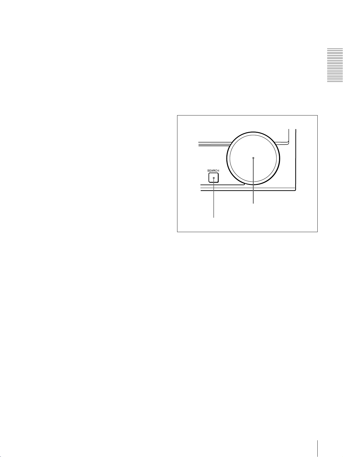
D Search control section
b Search dial
a SEARCH button
a SEARCH button
To use the search dial for playback in shuttle or jog mode,
press this button, turning it on. Pressing the dial toggles
between shuttle and jog modes. In shuttle mode, the
SHUTTLE indicator in the display section lights, and in
jog mode, the JOG indicator in the display section lights.
b Search dial
Turn this to carry out playback in the modes shown in the
following table. Turning the dial clockwise lights the G
indicator in the display section and plays back in the
forward direction. Turning the dial counterclockwise
lights the g indicator in the display section and plays back
in the reverse direction. When the tape is stopped, the s
indicator in the display section lights.
Pressing this dial toggles playback between shuttle mode
and jog mode. When playing back in shuttle mode, the
SHUTTLE indicator in the display section lights, and
when playing back in jog mode, the JOG indicator lights.
You can carry out noiseless playback in the range of ±
times normal speed.
1
/2
Chapter 1 Overview
k SHUTTLE/JOG indicators
When searching in shuttle mode using the search dial, the
SHUTTLE indicator lights, and when searching in jog
Location and Function of Parts
13
Page 14
Playback modes using the search dial
Playback mode Operation and functions
Shuttle Press the SEARCH button or the search
dial so that the SHUTTLE indicator in
the display section lights, then turn the
search dial.
Playback is carried out at a speed
determined by the position of the search
Chapter 1 Overview
Jog Press the SEARCH button or the search
dial. The maximum shuttle mode
playback speed can be changed with the
SHUTTLE menu item (see page 39).
dial so that the JOG indicator in the
display section lights, then turn the
search dial. Playback is carried out at a
speed determined by the speed of
rotation of the search dial. The playback
speed is up to
factory default.
The search dial has no detents.
±1 times normal speed by
You can use the SEARCH ENABLE menu item (see page
39) to select either of the following as the operation to be
performed to put the unit into search mode (shuttle or jog).
• Either press the SEARCH button or turn the search dial
(factory default setting).
• Press the SEARCH button.
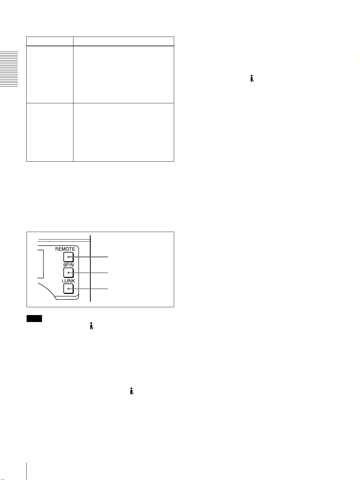
b 9PIN button
When carrying out remote control between this unit and
the unit connected to the REMOTE connector, press this
button, turning it on.
c i.LINK button
When carrying out remote control between this unit and
the unit connected to the DV IN/OUT connector, press
this button, turning it on.
E Remote control setting section
a REMOTE button
b 9PIN button
c i.LINK button
Note
When you edit using the DV IN/OUT connector, with
video and audio signal input set to “i.LINK” and remote
control set to “9PIN”, the locations where edit points are
actually set may not be the same as the specified locations.
When you set video and audio signal input to “i.LINK”, set
remote control to “i.LINK” as well.
a REMOTE button
When remote-controlling this unit from the unit connected
to the REMOTE connector (page 18) or DV IN/OUT
connector (page 17), press this button, turning it on.
When reverting to local mode to use the buttons in the tape
transport control section, press this button again, turning it
off.
Location and Function of Parts
14
Page 15
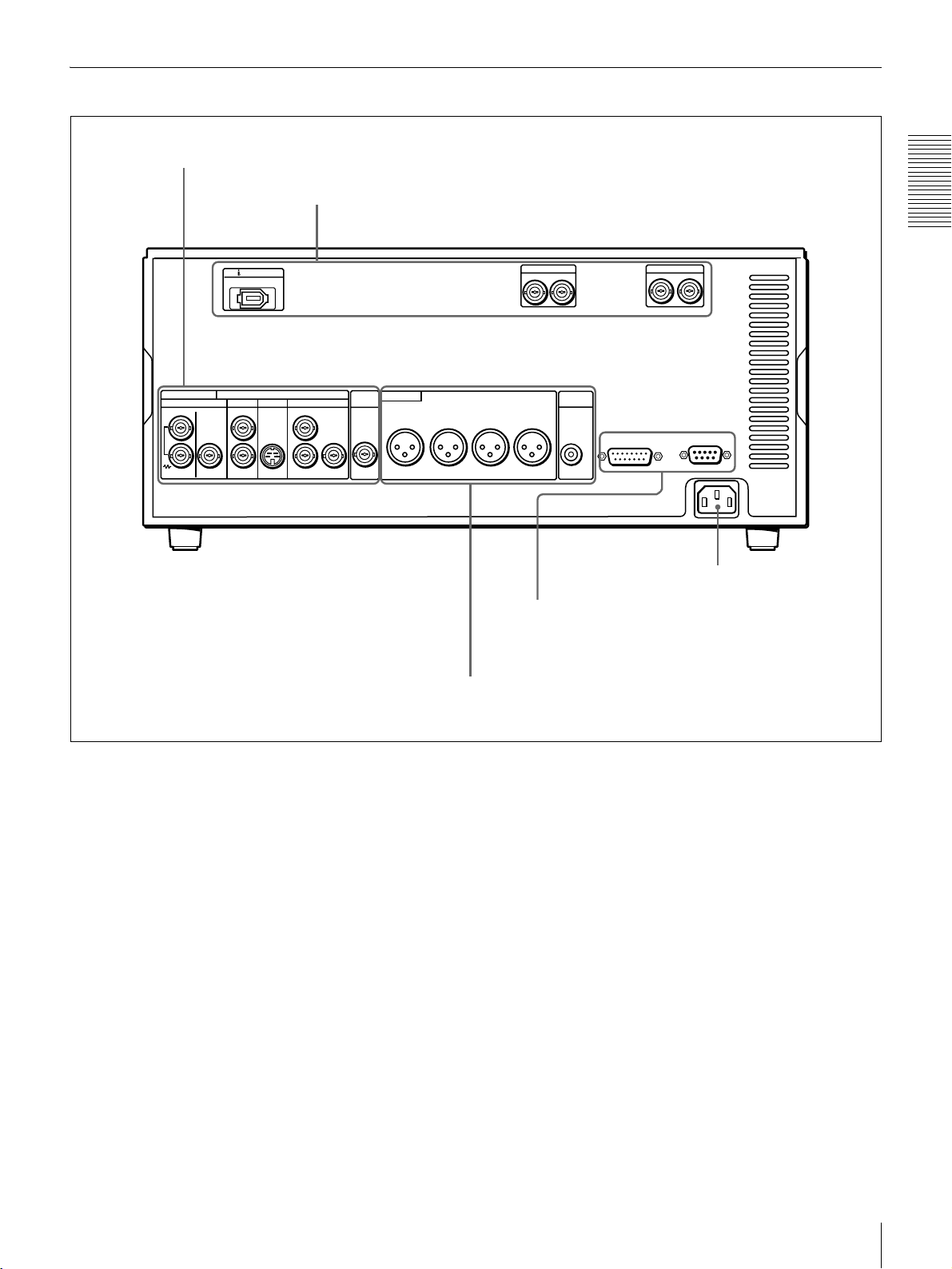
Rear Panel
A Analog video signal output section (see page 16)
B Digital signal output section (see page 17)
Chapter 1 Overview
ANALOG VIDEO
REF. VIDEO
IN OUT OUT
DV IN/OUT
VIDEO
1
2
(SUPER)
S VIDEO
COMPONENT VIDEO
OUT OUT
Y
R-Y
VIDEO CONTROL
AUDIO OUT(AES/EBU)
CH-1/2
CH-3/4
REMOTE
~AC IN
SDI OUT
12
TIME
AUDIO OUT
CODE
OUT
B-Y
CH-1
CH-2 CH-3
CH-4
MONITOR
OUT
AUDIO
AC IN connector
D External device connectors (see page 18)
C Analog audio signal output section (see page 17)
AC IN connector
Use the supplied power cord to connect this to an AC
outlet.
Location and Function of Parts
15
Page 16
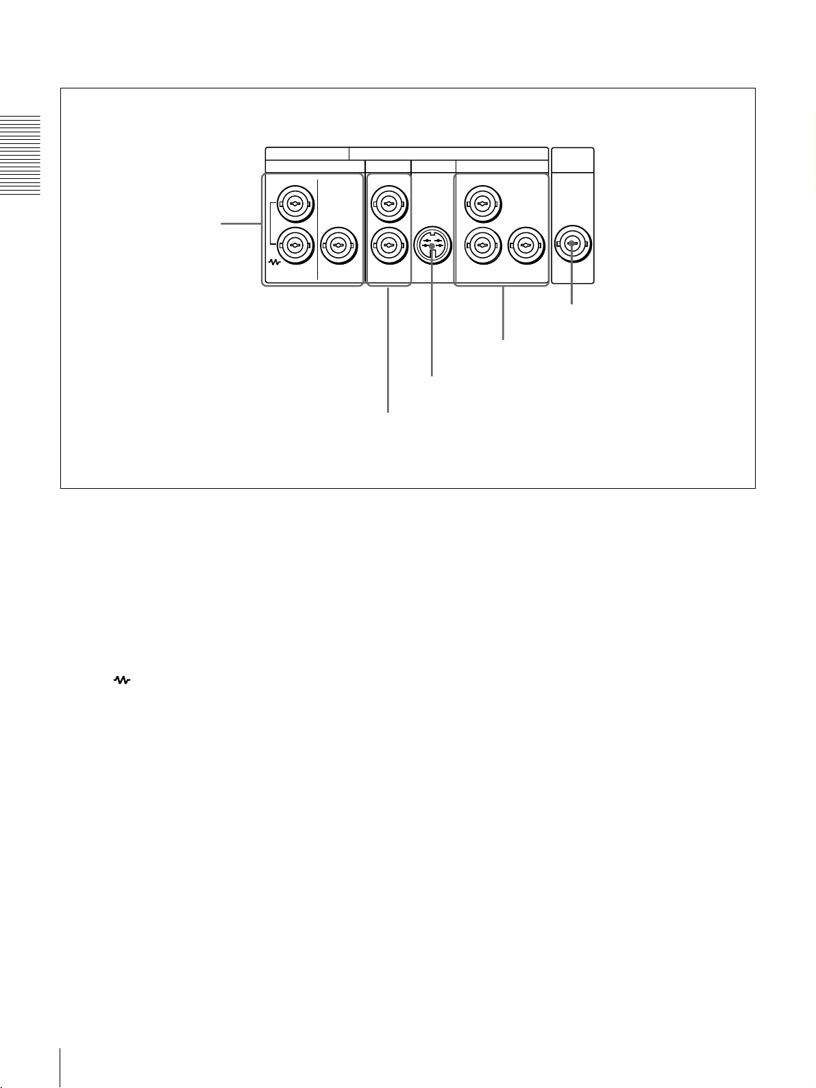
A Analog video signal output section
ANALOG VIDEO
REF. VIDEO
IN OUT OUT OUT OUT
Chapter 1 Overview
a REF. VIDEO IN/OUT
connectors
a REF. (reference) VIDEO IN/OUT connectors
(BNC type)
Input a reference video signal. The IN connector block has
a built-in automatic 75 Ω termination switch. When a
signal is input to the upper REF. VIDEO IN connector
with no bridging (loop-through) connection made, the
connector is terminated with an impedance of 75 Ω
automatically. To connect the reference video signal input
to the upper REF. VIDEO IN connector also to other
equipment, use the lower REF. VIDEO IN connector
(marked ). When the lower REF. VIDEO IN connector
is used, the built-in 75 Ω termination switch turns off
automatically.
The REF. VIDEO OUT connector outputs a reference
video signal.
TIME
VIDEO
S VIDEO
1
2
(SUPER)
b VIDEO OUT 1 and 2 (SUPER) connectors
COMPONENT VIDEO
Y
R-Y
c S VIDEO OUT connector
B-Y
d COMPONENT VIDEO OUT Y/R−Y/B−Y
connectors
CODE
OUT
d COMPONENT VIDEO OUT Y/R−Y/B−Y
connectors (BNC type)
These connectors output analog component video signals
(Y/R−Y/B−Y).
e TIME CODE OUT connector (BNC type)
Outputs the playback time code.
e TIME CODE OUT connector
b VIDEO OUT 1 and 2 (SUPER) connectors (BNC
type)
These connectors output analog composite video signals.
When the CHARA. DISPLAY menu item (see page 40) is
set to ON (factory default setting), connector 2 (SUPER)
outputs a signal with superimposed text information.
c S VIDEO OUT connector (4-pin)
This connector outputs an S-video signal with separated Y
(luminance) and C (chroma: 3.58 MHz for DSR-1600A or
4.43 MHz for DSR-1600AP) components.
Location and Function of Parts
16
Page 17
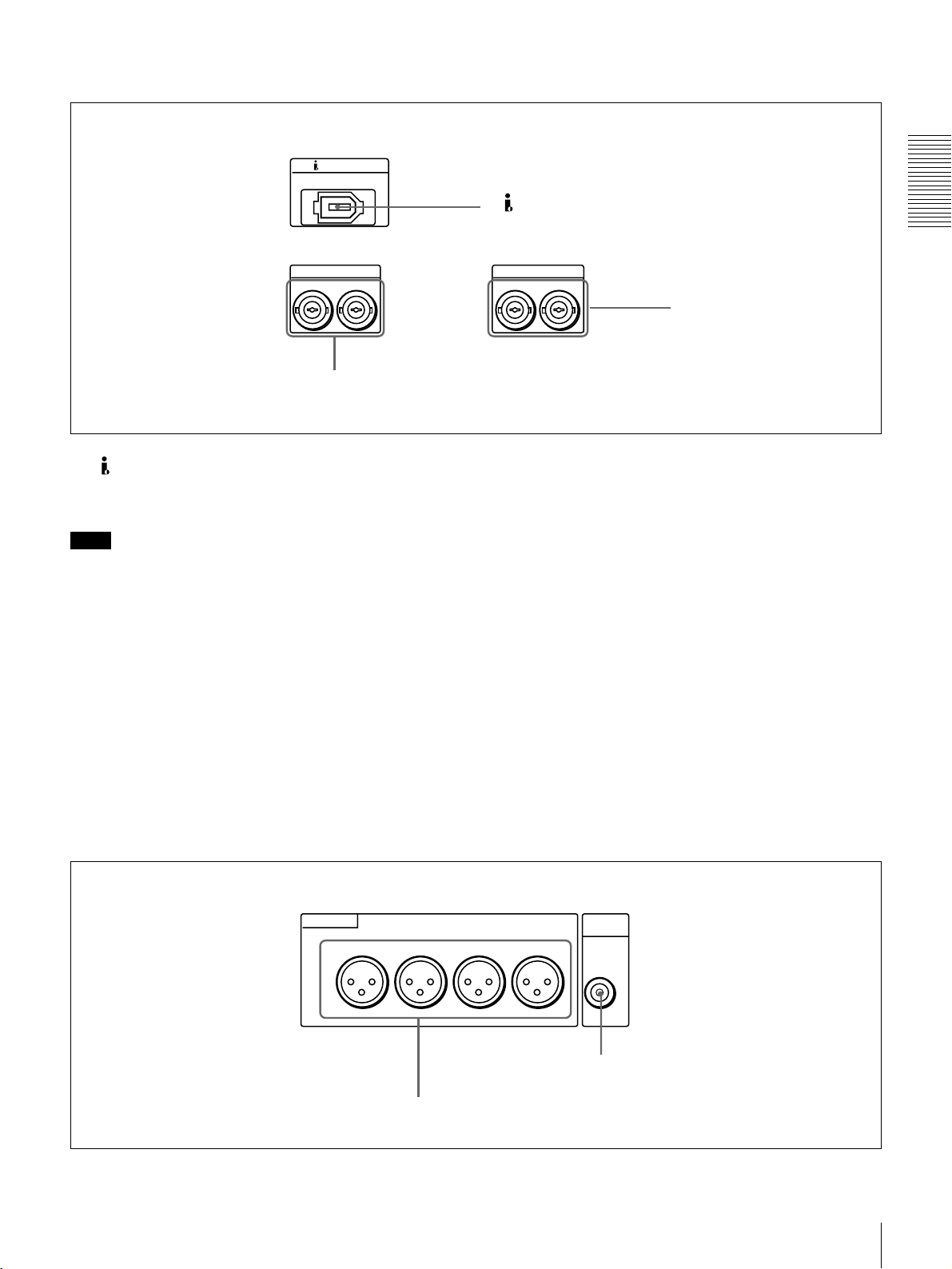
B Digital signal output section (optional DSBK-1601 board required)
DV IN/OUT
a DV IN/OUT connector
Chapter 1 Overview
SDI OUT
2
1
2 SDI OUT connectors
a DV IN/OUT connector (6-pin IEEE-1394)
This i.LINK-compatible connector outputs digital video
and audio signals in DV format.
Note
• When searching at speeds in the range +1/2 to +1/30 or
1
−
/2 to −1/30 times normal speed, the audio signal output
from this connector and monitored on external
equipment may sound differently from the audio signal
played back on this unit.
• When you connect this unit to another device with a 6pin DV connector, always power the other device off and
unplug its power cord from the power output before
connecting or disconnecting the i.LINK cable (DV
cable). If you connect or disconnect the cable with the
power cord still plugged in, power from the DV
connector may flow into this unit, possibly damaging
this unit.
AUDIO OUT(AES/EBU)
CH-1/2
CH-3/4
3 AUDIO OUT (AES/EBU)
connectors
• When you connect this unit to another device with a 6pin DV connector, make the connection to the 6-pin DV
connector on the other device before making the
connection to this unit.
b SDI (Serial Digital Interface) OUT connectors
(BNC type) (optional DSBK-1601 SDI/AES/EBU
Output Board required)
Output SDI-format digital video and audio signals. The
same signals are output from both connectors.
c AUDIO OUT (AES/EBU) connectors (BNC type)
(optional DSBK-1601 SDI/AES/EBU Output
Board required)
These connectors output digital audio signals in AES/EBU
format. The left connector (CH-1/2) is for audio channels
1 and 2, and the right connector (CH-3/4) is for audio
channels 3 and 4.
C Analog audio signal output section
AUDIO OUT
CH-1
CH-2 CH-3
MONITOR
OUT
CH-4
a AUDIO OUT CH-1 to CH-4 connectors
AUDIO
b AUDIO MONITOR OUT connector
Location and Function of Parts
17
Page 18
a AUDIO OUT CH-1 (channel 1) to CH-4 connectors
(XLR 3-pin, male)
These connectors output channel-1 to channel-4 analog
audio signals, respectively.
It is possible to use the AUDIO OUT CH-3 and AUDIO
OUT CH-4 connectors for audio monitor output for
channels 1 and 2, respectively (use the OUTPUT CH3/4
menu item (see page 43).
Chapter 1 Overview
b AUDIO MONITOR OUT connector (RCA phono
jack)
This connector outputs audio signals for monitoring. The
audio signals to be output from this connector can be
selected with the MONITOR SELECT switches on the
menu control panel.
D External device connectors
VIDEO CONTROL
a VIDEO CONTROL connector
REMOTE
b REMOTE connector
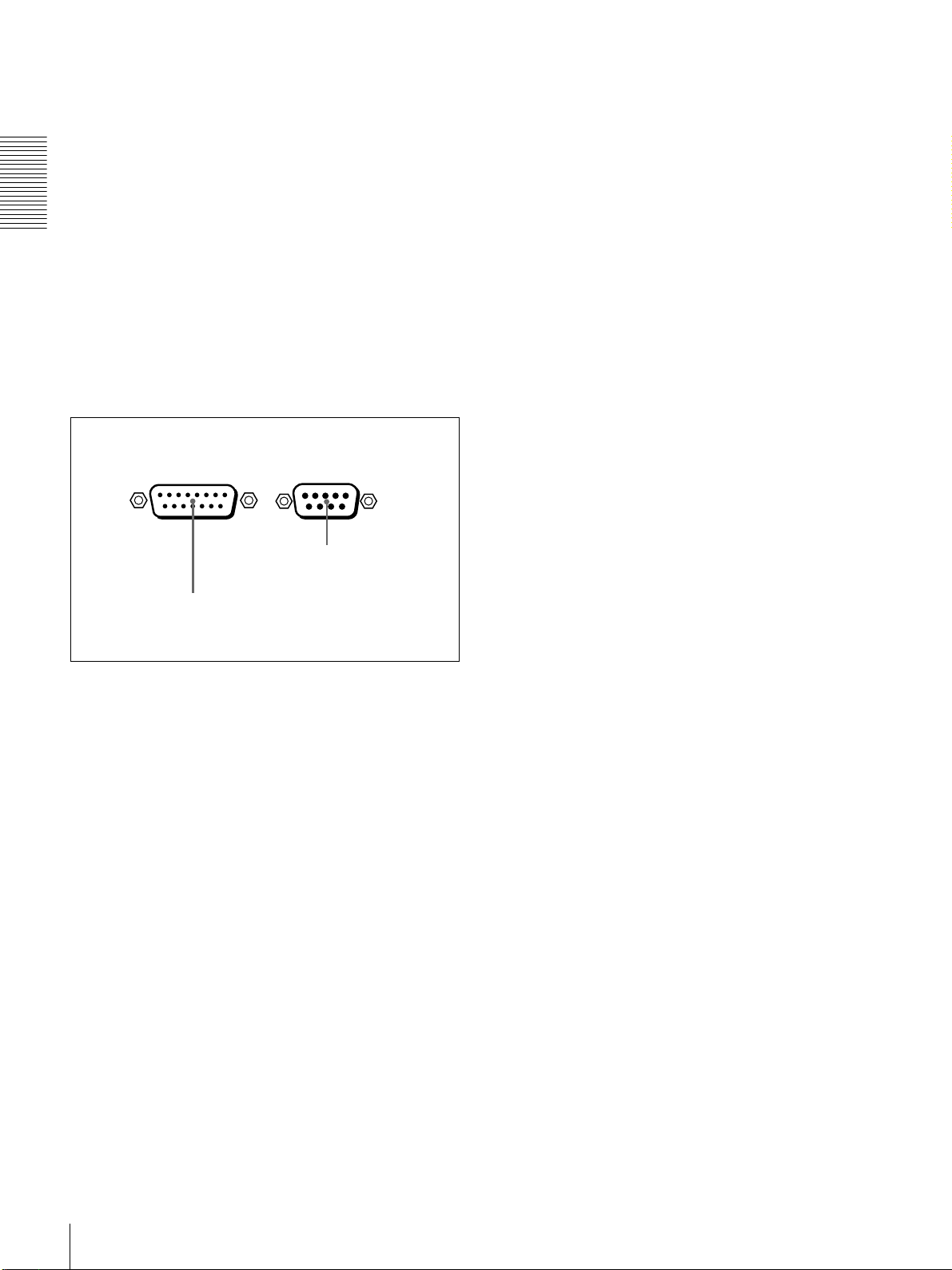
a VIDEO CONTROL connector (D-sub 15-pin)
For remote control of the internal digital video processor,
connect an optional remote control unit to this connector.
b REMOTE connector (D-sub 9-pin)
Use the optional 9-pin remote cable to connect an editing
controller that supports this unit, or a VCR that supports
editing with two units (DSR-2000A/2000AP, etc.), to
connect those devices to this unit for remote control.
Location and Function of Parts
18
Page 19
Playback
Usable Cassettes
Playback
This section describes the necessary settings and operations to perform playback
on this unit. The same settings and operations apply whether you are using the
unit as part of an editing system, for dubbing, or as a stand-alone player VCR.
For the necessary connections and settings not covered in this section, see
Chapter 5 “Connections and Settings (page 49).”
This unit can use the DVCAM cassettes listed below.
Model name Size
PDV-34*/64*/94*/124*/184* Standard size
PDVM-12*/22*/32*/40* Mini size
Chapter 2
The * in each model name is actually “ME” (indicating that a cassette memory
is contained), or “N” (indicating that no cassette memory is contained).
The numbers in each model name indicate the maximum playback time (in
minutes) for each model. For example, the PDV-184ME has a maximum
playback time of 184 minutes.
Other usable cassettes
Large- and medium-size DVCPRO (25M) cassettes can also be played back on
this unit.
Notes
• If you insert an incorrect type of cassette, it will be automatically ejected.
• Although this unit can use DV series consumer cassettes, video or audio noise
may occur on some tapes.
For reliable playback, editing, recording, and storage, use DVCAM cassettes.
• See the note in page 12.
Playback
19
Page 20
DVCAM cassettes
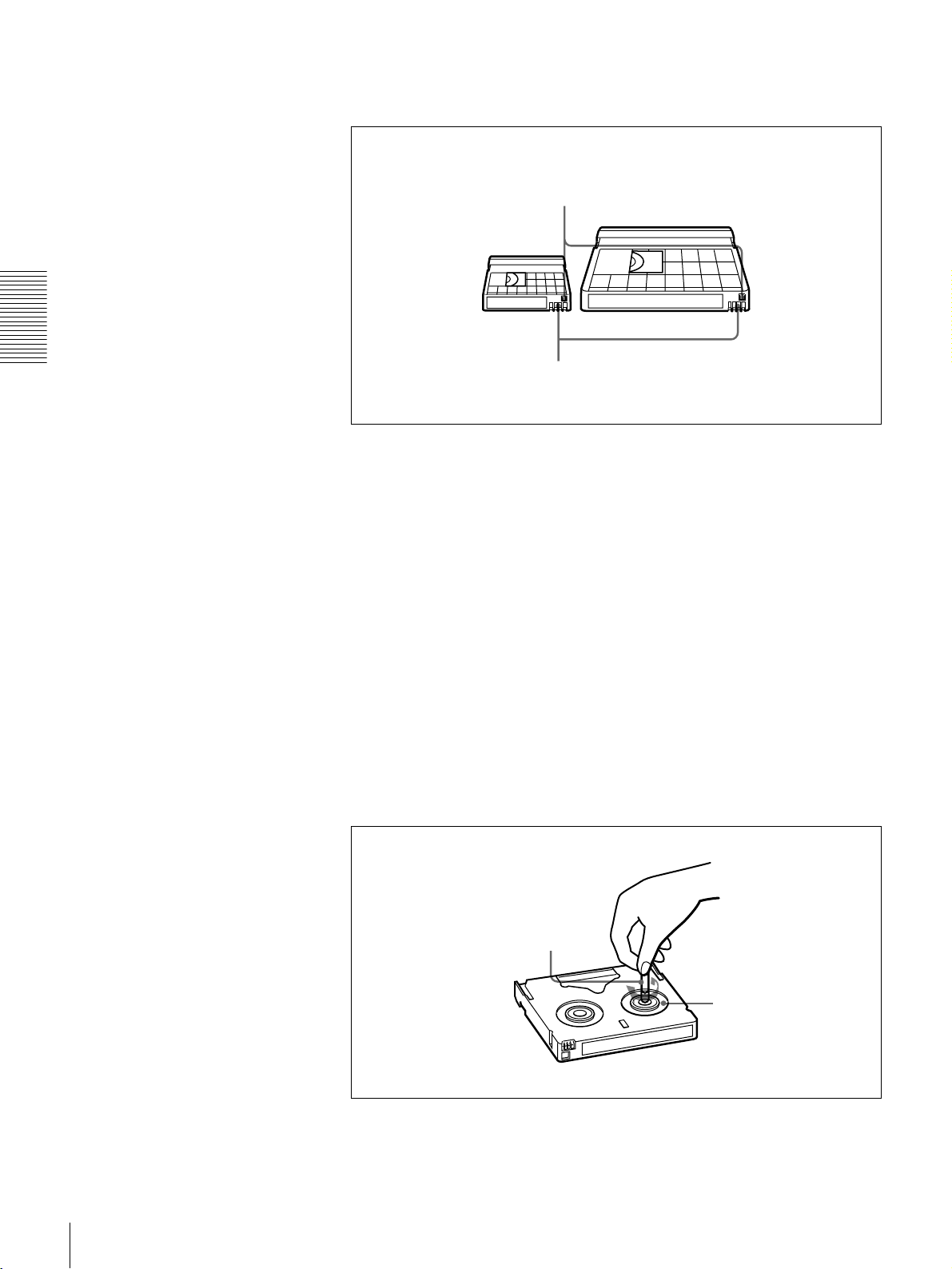
The following figure illustrates the DVCAM cassettes.
REC/SAVE switch
Set to SAVE to prohibit recording on the tape.
Mini size Standard size
Chapter 2 Playback
Notes on using cassettes
Checking the tape for slack
Cassette memory
• Before storing the cassette for a long period of time, rewind the tape to the
beginning and be sure to put the cassette in its storage case, preferably on end
instead of flat on its side.
Storing a cassette in any other condition (not rewound, out of its case, etc.)
may cause the video and audio contents to become damaged over time.
• If the cassette memory connector (contact point) becomes dirty, connection
problems may occur, causing a loss of functions. Remove away any dust or
dirt from this area before using the cassette.
• If the cassette is dropped on the floor or otherwise receives a hard impact, the
tape may become slackened and may not play back correctly.
For information about how to check the tape for slack, see the next section.
Using a paper clip or a similar object, turn the reel gently in the direction shown
by the arrow. If the reel does not move, there is no slack. Insert the cassette into
the cassette compartment, and after about 10 seconds take it out.
20
Paper clip, etc.
Reel
Playback
Page 21
Inserting and Ejecting Cassettes
Inserting a cassette
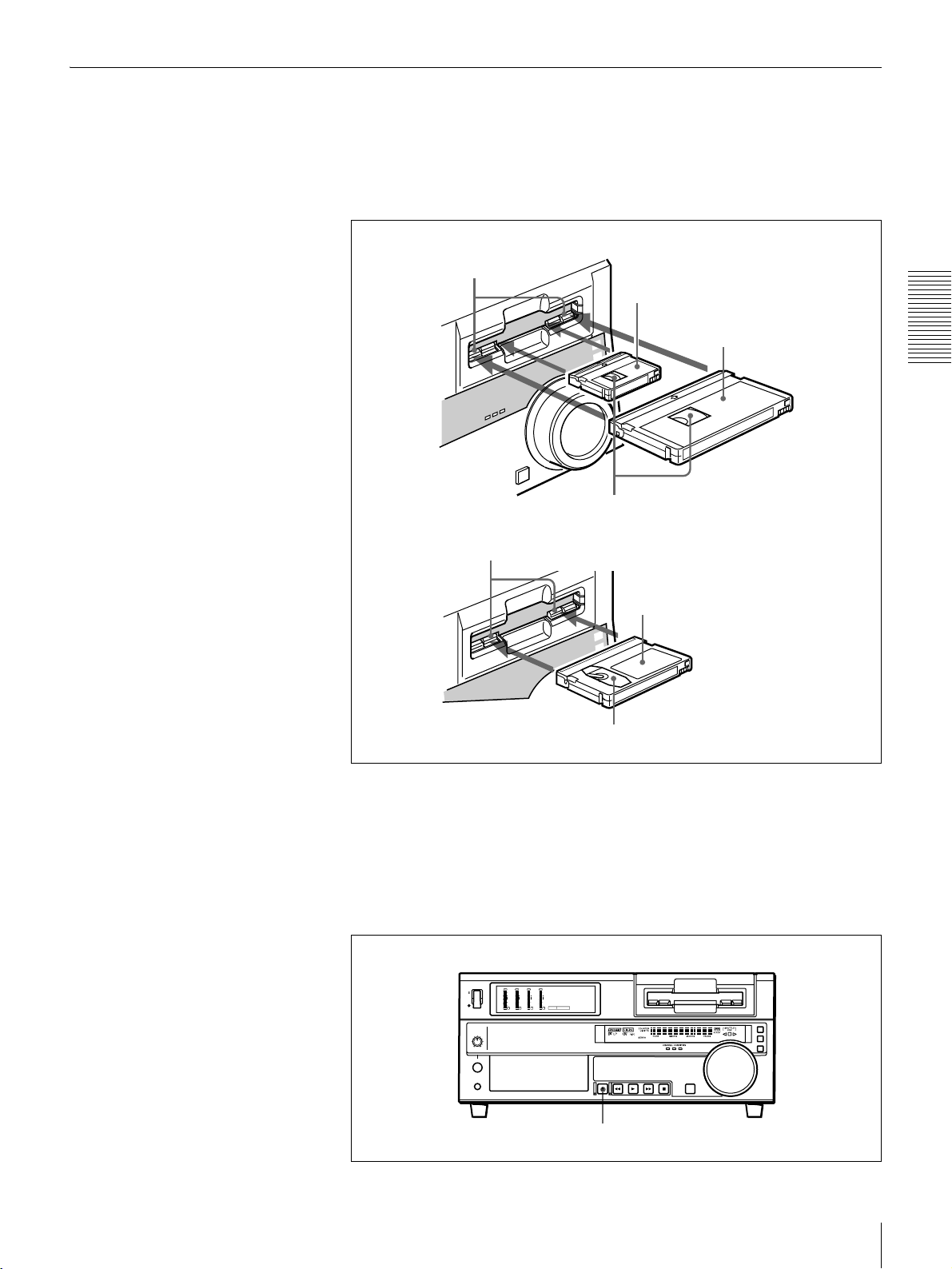
This unit accepts three sizes of cassette: L (standard size), M (medium size:
DVCPRO) and S (mini size). When inserting a cassette in the unit, make sure
its tape window faces upward as shown in the following figure.
Outer guides
Inner guides
Mini size (Insert the cassette into the
middle of the cassette compartment.)
Standard size
Chapter 2 Playback
Tape window facing upward
Medium size (Align the cassette with
the outer guides, then slide it in over
the inner guides.)
Tape window facing upward
No double insertion of cassettes
When you insert a cassette, the orange lock-out plate appears in the cassette
compartment to prevent double insertion.
Ejecting a cassette
Press the EJECT button.
OVER
OVER
OVER
OVER
dB
dB
dB
dB
dB
dB
dB
dB
0
0
0
0
0
0
0
0
-12
1
-12
1
-12
1
-12
1
-20
0
-20
0
-20
0
-20
0
-1
-1
-1
-1
-30
-30
-30
-30
-40
-40
-40
-40
-2
-2
-2
-2
PB FS
-60
1
48k44.1k32k
-60
-60
-60
2
3
4
EJECT button
Playback
21
Page 22
Settings for Playback
Chapter 2 Playback
Video monitor
2
Player (DSR-1600A/1600AP)
OVER
OVER
OVER
OVER
dB
dB
dB
dB
dB
dB
dB
dB
0
0
0
0
0
0
0
0
1
1
1
1
-12
-12
-12
-12
0
0
0
0
-20
-20
-20
-20
-1
-1
-1
-1
-30
-30
-30
-30
-40
-40
-40
-40
-2
-2
-2
-2
PB FS
1
-60
1
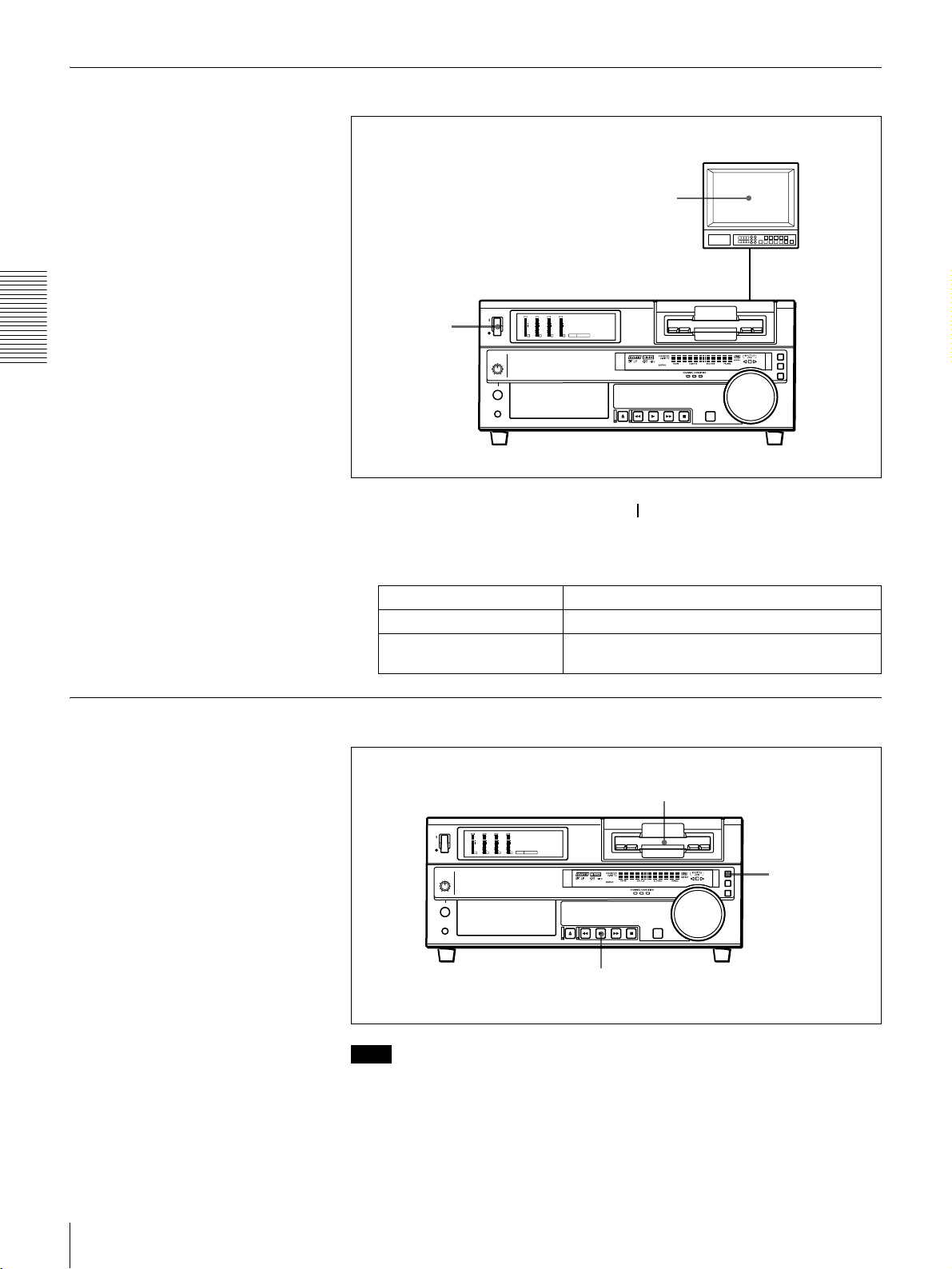
1 Power on this unit by pressing on the side of the POWER switch.
48k44.1k32k
-60
-60
-60
2
3
4
Playback Procedure
2 Power on the video monitor and set its switches as shown below.
Switch Setting
75 Ω termination switch ON (or attach a 75 Ω terminator.)
Input switch Set according to the type of input signal from this
unit.
1
OVER
OVER
OVER
OVER
dB
dB
dB
dB
dB
dB
dB
dB
0
0
0
0
0
0
0
0
1
1
1
1
-12
-12
-12
-12
0
0
0
0
-20
-20
-20
-20
-1
-1
-1
-1
-30
-30
-30
-30
-40
-40
-40
-40
-2
-2
-2
-2
PB FS
-60
1
48k44.1k32k
-60
-60
-60
2
3
4
REMOTE button
2
22
Note
When controlling this unit from an editing control unit connected to the
REMOTE connector (see page 18) on this unit, press the REMOTE button to
turn it on. When not, turn the button off.
1 Insert a cassette.
Playback
Page 23
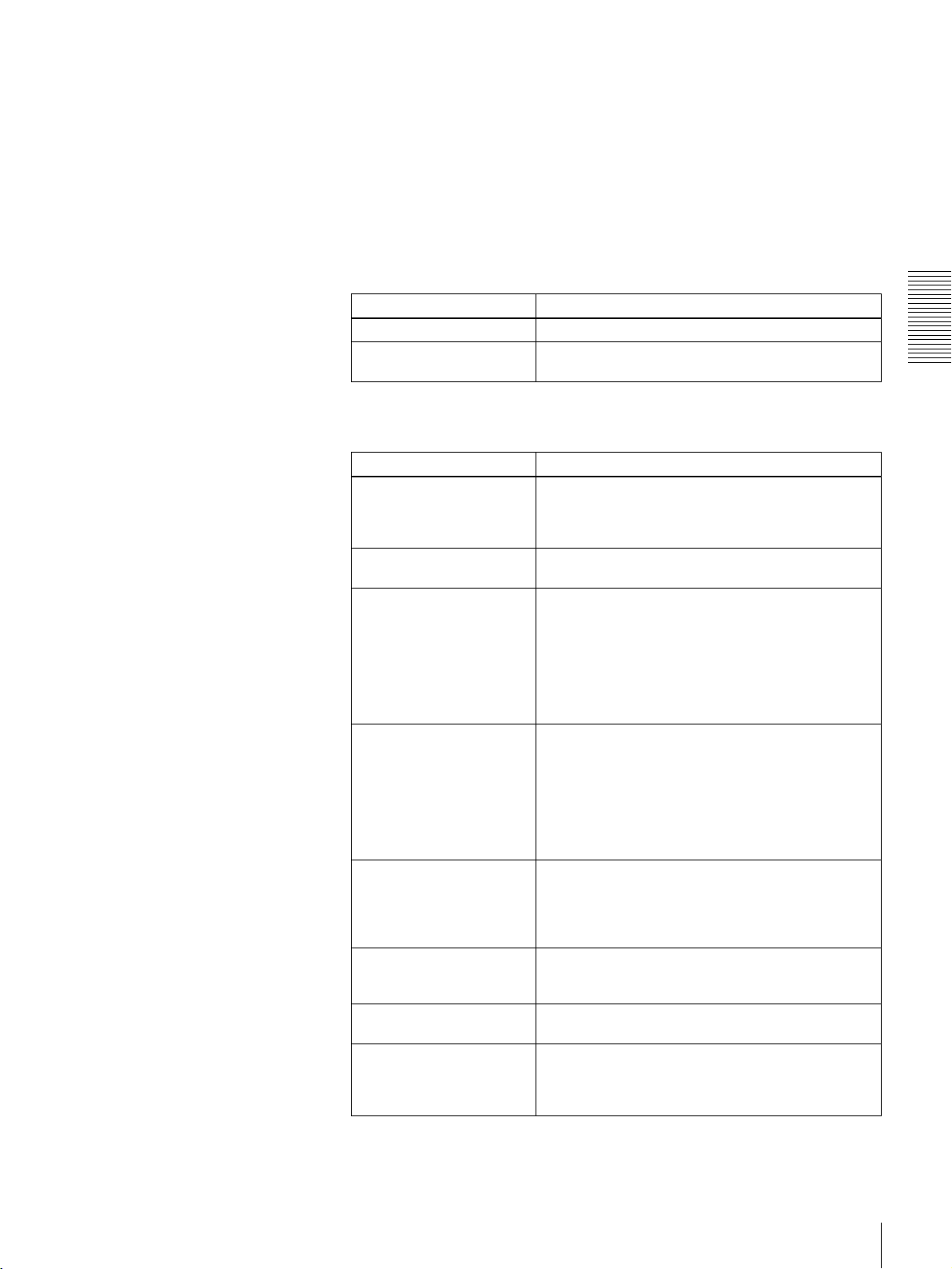
For details of cassette insertion see page 21, and for usable cassette types
see page 19.
The cassette is automatically drawn into the unit. The STOP button will
light, and a few seconds later a still image will appear on the monitor screen.
2 Press the PLAY button.
This starts the playback operation. When the tape is played back all the way
to the end, the unit automatically rewinds it and then stops.
If the following indicators light when a cassette is loaded
Indicator It means:
Cassette memory indicator The loaded cassette contains a cassette memory.
ClipLink indicator There is ClipLink log data stored in the cassette
To perform the following operations
Operation Do this:
Stop playback. Press the STOP button.
Adjust the audio playback
level.
Play back in shuttle mode
while monitoring the video.
Play back in jog mode while
monitoring the video.
Inhibit the unit from
outputting text information
(time data, operation mode
indications, etc.) to the
video monitor.
Remove the cassette. Press the EJECT button.
Disable the automatic
rewind function.
Change the time period
before the unit switches
from stop mode to standby
off mode.
memory on the loaded cassette.
The unit enters stop mode, and will automatically
switch to standby off mode after the time set with the
STOP TIMER menu item (see page 41).
Use the audio level control on the monitor.
Press the SEARCH button or search dial to light the
SHUTTLE indicator in the display section, then rotate
the search dial.
Playback is carried out at the speed determined by
the angular position of the search dial.
The maximum speed for shuttle playback can be
changed using the SHUTTLE menu item (see page
39).
Press the SEARCH button or search dial to light the
JOG indicator in the display section, then rotate the
search dial.
Playback is carried out at the speed according to the
speed of the search dial rotation. The playback
speed range is ±1 times normal speed by factory
default.
The search dial has no detents.
Set the CHARA. DISPLAY menu item (see page 40)
to OFF.
If a CNT value is shown on the time counter display,
the CNT value is reset.
Set the AUTO REW menu item (see page 39) to
DISABLE.
Change the setting of the STOP TIMER menu item
(see page 41).
Chapter 2 Playback
Playback
23
Page 24

Repeat Playback—Automatic Cyclical Playback
Proceed as follows to perform automatic cyclical playback of recording (repeat
playback) between selected start and end points.
1 Set the desired repeat start and end points using the REPEAT FUNCTION
menu item (see page 38).
You can set points A and B as start and end points by following the
procedure described in the next section.
2 Set the REPEAT MODE menu item (see page 38) to ON.
The REPEAT indicator lights.
3 Press the SET (YES) button to save the new setting and close the menu.
Chapter 2 Playback
4 Press the PLAY button.
The unit repeats playback between the repeat start and end points set in step
1.
Setting Points A and B for Repeat Playback
You can set the repeat playback start point (point A) and end point (point B) by
using the current tape position or inputting time code values.
To perform repeat playback after setting points A and B, press the PLAY button
when the REMOTE button is off. When the DSRM-10 Remote Control Unit is
connected to the CONTROL S connector on the front panel, you can also start
repeat playback by pressing its PLAY button with the REMOTE button of this
unit off.
Setting the current tape position as point A or B
Proceed as follows to set the current tape position as point A or B for repeat
playback.
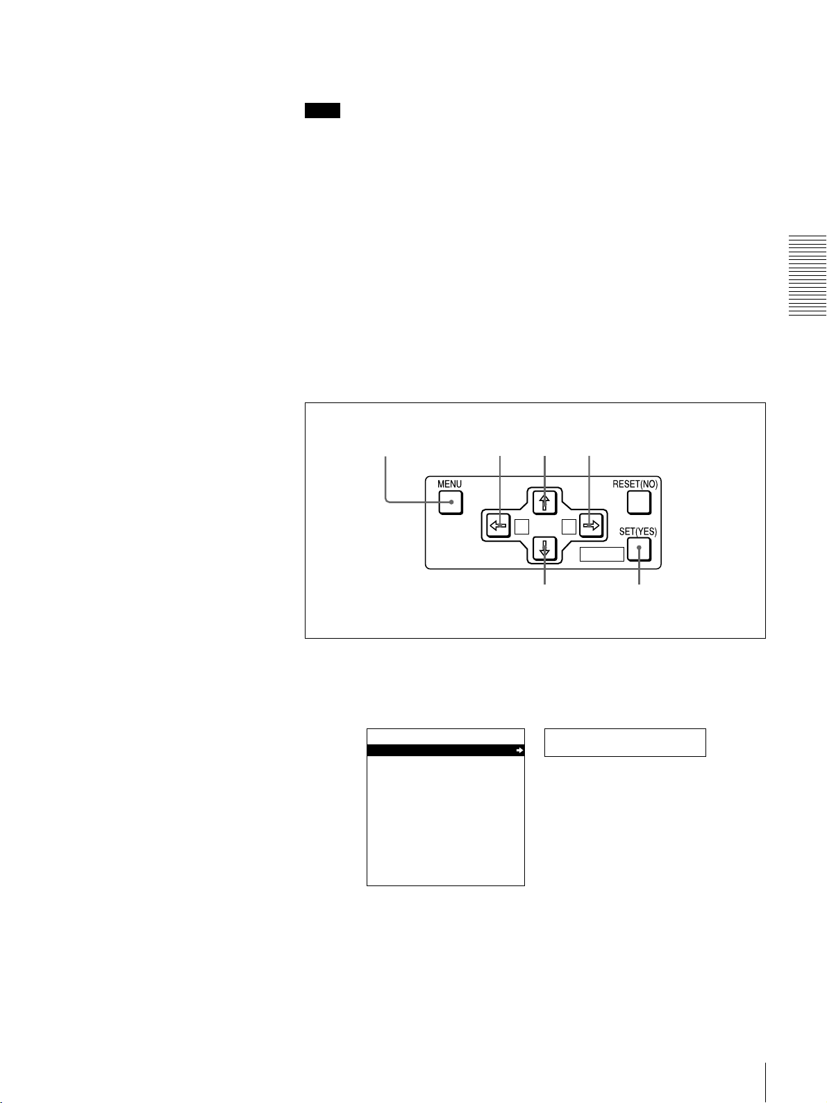
Buttons used for setting the
current tape position as point B
In the following explanation of how to set points A and B for repeat
playback, these three buttons are referred to as the KA button,
Bk button, and SET (YES) button, respectively.
While holding down the SET (YES) button on the menu control panel,
press the KA or Bk button. The time code value of the current tape
position is set as point A or B, and a message “A set” or “B set” is displayed for
0.5 second in the time counter display.
Buttons used for
setting the current
tape position as
point A
A B
MARK
MARK
MARK
24
Playback
Page 25
Once set, the point A or B time code value is held in the non-volatile memory
of the unit until changed. It is not lost when the unit is powered off.
Note
When setting point A or B, you can only use a time code value. Even when
COUNTER is selected with the COUNTER SEL button, you cannot use a CNT
value to set point A or B.
To check the point A or B time code value
Press the KA or Bk button on the menu control panel. While the button is
held down, the point A or B time code value is displayed on the monitor and in
the time counter display.
If you hold down the KA and Bk buttons simultaneously, the value shown
is the point B time code value minus the point A time code value. If the point A
time code value is greater than the point B time code value, a minus sign (−) is
shown before the value.
Inputting time code values for points A and B
Using the following procedure, you can modify the time code value for point A
or B.
Chapter 2 Playback
1,15
8,11 12 2,3,4,6,10,11
1 Press the MENU button.
The following menu display appears.
SYSTEM MENU
SETUP MENU
HOURS METER
A B
MARK
5,7,9,12 13
Setup menu
Time counter display
Monitor screen
Playback
25
Page 26
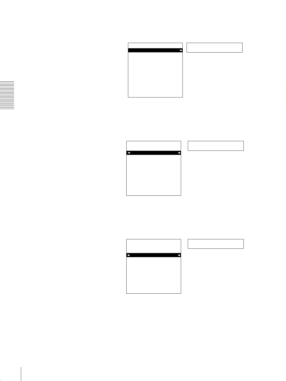
2 With “SETUP MENU” selected, press the Bk button.
The display changes as follows.
OPERATIONAL FUNCTION
SETUP MENU
DISPLAY CONTROL
TIME CODE
SETUP BANK OPERATION
MENU GRADE :BASIC
Monitor screen
Chapter 2 Playback
Operational
Time counter display
3 With “OPERATIONAL FUNCTION” selected, press the Bk button.
The display changes as follows.
OPERATIONAL FUNCTION
SETUP MENU
REPEAT FUNCTION
LOCAL ENABLE :STP&EJ
>REP FUNC
Time counter display
Monitor screen
4 With “REPEAT FUNCTION” selected, press the Bk button.
The contents of the REPEAT FUNCTION menu item are displayed.
OPERATIONAL FUNCTION
SETUP MENU
REPEAT FUNCTION
REPEAT MODE
REPEAT TOP
REPEAT END
A PRESET
B PRESET
Monitor screen
:OFF
:
T.TOP
:
V.END
>> REPEAT MD
Time counter display
26
Playback
Page 27

5 Press the j button to select “REPEAT TOP.”
OPERATIONAL FUNCTION
SETUP MENU
REPEAT FUNCTION
REPEAT MODE
REPEAT TOP
REPEAT END
A PRESET
B PRESET
Monitor screen
6 Press the Bk button.
The display changes as follows.
SETUP MENU
OPERATIONAL FUNCTION
REPEAT FUNCTION
REPEAT TOP
* TAPE TOP
A POINT
:OFF
:
T.TOP
:
V.END
T.TOP
:
:
V.END
>> REP TOP
Time counter display
Chapter 2 Playback
>>> Tape top
Time counter display
Monitor screen
7 Press the j button to select “A POINT.”
OPERATIONAL FUNCTION
REPEAT FUNCTION
REPEAT TOP
* TAPE TOP
A POINT
SETUP MENU
Monitor screen
T.TOP
:
:
V.END
>>> A point
Time counter display
Playback
27
Page 28

8 Press the KA button.
The display changes as follows.
OPERATIONAL FUNCTION
REPEAT FUNCTION
REPEAT MODE
REPEAT TOP
REPEAT END
A PRESET
B PRESET
Chapter 2 Playback
SETUP MENU
Monitor screen
:OFF
.
A
:
V.END
>> REP TOP
Time counter display
9 Press the j button to select “A PRESET.”
OPERATIONAL FUNCTION
SETUP MENU
REPEAT FUNCTION
REPEAT MODE
REPEAT TOP
REPEAT END
A PRESET
B PRESET
:OFF
.
A
:
V.END
>> A preset
Time counter display
Monitor screen
10Press the Bk button.
The A PRESET MODE screen appears. The time code value of the current
point A is displayed below the screen title.
A PRESET MODE
A 00:00:00:00
INC/DEC : ( )( )KEY
SHIFT : ( )( )KEY
CLEAR : RESET KEY
DATA SAVE : SET KEY
TO MENU : MENU KEY
Monitor screen
11Use the KA or Bk button to select the digit in the time code value
display that you want to change.
Each press of the button causes the digit to the left or right to begin flashing.
Holding the button down moves the flashing digit continuously. If you want
to clear the time code value, press the RESET (NO) button. The value is
cleared to 00:00:00:00, and the leftmost digit begins flashing.
28
Playback
Page 29
12Press the J or j button to increment or decrement the value of the flashing
digit.
Each press of the button increments or decrements the value. Holding the
button down increments or decrements the value continuously. To change
other digits, return to step 11.
13Press the SET (YES) button to confirm the defined value.
The message “NOW SAVING...” is displayed on the monitor screen and
“Saving...” is shown in the time counter display while the new setting is
being saved in memory.
Caution
The new setting may be lost if you power off the unit during the saving
operation. Wait until the saving operation is completed before powering off
the unit.
If you want to discard the changed value
Press the MENU button instead of pressing the SET (YES) button
to return to the menu display, then press the MENU button again to end the
menu operation without saving the changed value into memory.
After the saving operation is completed, the monitor screen and time
counter display return to the REPEAT FUNCTION setting display as
shown in step 9.
MARK
MARK
14To set point B, refer to steps 5 to 13. (Select “REPEAT END” in step 5, “B
POINT” in step 7, and “B PRESET” in step 9.)
15Press the MENU button to close the menu.
Chapter 2 Playback
Cuing Up to Any Desired Position Set as Point A or B
You can set any desired tape position as point A or B and cue up to the set point
when required. To cue up to point A or B, holding down the KA or Bk
button on the menu control panel, press the REW button in the tape transport
control section.
For the methods of setting points A and B, see “Setting Points A and B for
Repeat Playback” (page 24).
Playback
29
Page 30

Convenient Functions
for Editing Operation
Displaying Time Data and Other Text Information
This unit allows time data and operation mode indications
to be displayed on the monitor screen.
Time data can also be displayed in the time counter display
on the unit.
Displaying Time Data and Operation Mode Indications
The unit is provided with the following functions related to
time data.
• Display and reset CNT value
• Display and play back SMPTE/EBU time code and user
bit data
• Display and play back VITC
The unit can output the time code read from the tape as an
analog (LTC) signal while in normal-speed playback
mode.
Note
The unit outputs no signal from the TIME CODE OUT
connector unless it is in normal-speed playback mode.
Chapter 3
Use the DISPLAY CONTROL menu items (see page 40)
to select the information displayed and the character type
and position of the indications.
Monitor screen contents
The contents of the monitor screen are shown below.
A Time data type
Time data
B Drop frame indication
for time code reader
TCR
a) This character (.) can appear on the DSR-1600A only. The
character to appear in this column is always a colon ( : ) on the
DSR-1600AP.
00:04 47.07*
PLAY
D DSR-1600A/1600AP operation mode
:
LOCK
a)
C VITC field
indication
To view time data and operation mode
indications on the monitor screen
Set the CHARA. DISPLAY menu item (see page 40) to
ON (factory default setting).
The time data and the indication of the current operation
mode are superimposed on the video signal that is being
output from the VIDEO OUT 2 (SUPER) connector, and
can be viewed on the monitor screen.
Displaying Time Data and Other Text Information
30
Page 31
A Time data type
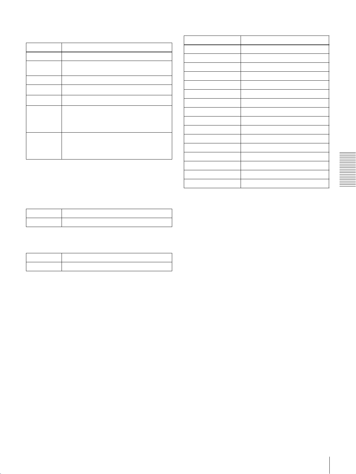
The following time data type indications are displayed.
Indication Description
CNT Count value of the time counter
TCR Time code data from time code reader
(factory default setting)
UBR User bit data from time code reader
TCR.
UBR.
T*R
b)
Time code data from VITC reader
User bit data from VITC reader
Time code data from time code reader. The
asterisk indicates an interpolation by the time
a)
a)
code reader to make up for the time code
data not correctly read from the tape.
U*R
b)
User bit data from the time code reader. The
asterisk indicates that last data is retained by
the time code reader, as the new data has
not been read correctly from the tape.
a) You can switch between TC and VITC using the TC SELECT menu item
(see page 41).
b) “*” is displayed when data cannot be read in correctly.
B Drop frame indication for time code reader (on
DSR-1600A only)
D DSR-1600A/1600AP operation mode
Display Operation mode
CASSETTE OUT Cassette is not loaded.
THREADING Tape loading
UNTHREADING Tape unloading
STANDBY OFF Standby off mode
T. RELEASE Tape tension released
STOP Stop mode
F. FWD Fast forward mode
REW Rewind mode
PREROLL Preroll mode
PLAY Playback mode (servo unlocked)
PLAY LOCK Playback mode (servo locked)
PLAY-PAUSE Temporary stop of playback
JOG STILL Still picture in jog mode
JOG FWD Jog mode in forward direction
JOG REV Jog mode in reverse direction
SHUTTLE (Speed) Shuttle mode
Chapter 3 Convenient Functions for Editing Operation
. Drop frame mode (factory default setting)
: Non-drop frame mode
C VITC field indication
(blank) Display fields 1 and 3.
* Display fields 2 and 4.
Displaying Time Data and Other Text Information
31
Page 32
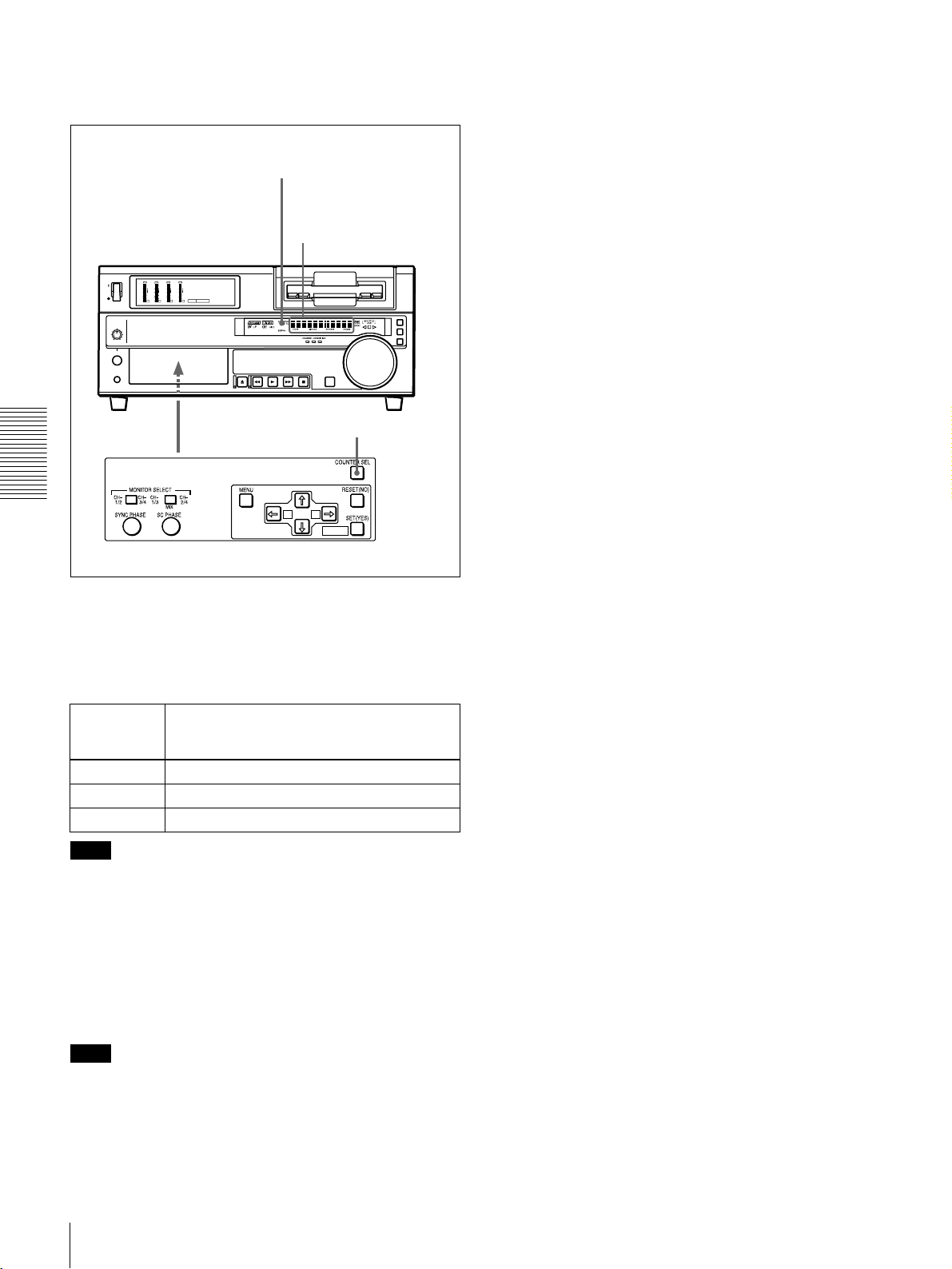
To display the desired time data in the time
counter display
Time data type indicators
Time counter display
OVER
OVER
OVER
OVER
dB
dB
dB
dB
dB
dB
dB
dB
0
0
0
0
0
0
0
0
-12
1
-12
1
-12
1
-12
1
-20
0
-20
0
-20
0
-20
0
-1
-1
-1
-1
-30
-30
-30
-30
-40
-40
-40
-40
-2
-2
-2
-2
PB FS
-60
1
48k44.1k32k
-60
-60
-60
2
3
4
COUNTER SEL button
Chapter 3 Convenient Functions for Editing Operation
A B
MARK
Open the door on the lower part of the front panel, and
press the COUNTER SEL button.
Each press of this button cycles through three options:
CNT value, time code, and user bit data. The time data type
indicator for each option lights as it is selected.
Time data
type
indicator
COUNTER CNT (count value of the time counter)
TC Time code
U-BIT User bit data
Note
Time data shown in the time counter
display
When the REMOTE button is lit, the COUNTER SEL
button does not operate while the tape is moving. In such
cases, use the external equipment connected to the
REMOTE connector on the rear panel to select the time
data.
To reset the CNT value
Press the RESET (NO) button on the menu control panel.
This resets the CNT value to 0:00:00:00.
Note
During playback, if the recording on the tape includes
discontinuities, the counter may operate incorrectly at the
corresponding points.
Displaying Time Data and Other Text Information
32
Page 33

High-Speed and LowSpeed Search—Quickly
and Accurately
Determining Editing
Points
Use the search function to easily locate the desired scene
and to quickly and accurately determine edit points.
Search Operations via External Equipment
External equipment Buttons in the remote control
setting section
Editing control unit
connected to the
Turn on both the REMOTE and 9PIN
buttons.
REMOTE connector
SIRCS-compatible
Turn off the REMOTE button.
remote control unit
connected to the
CONTROL S
connector
Equipment connected
to the DV IN/OUT
Turn on both the REMOTE and
i.LINK buttons.
connector
For description on how to carry out search operations via
external equipment, see the operating instructions for the
equipment.
You can control the unit in the following operation modes
from an editing control unit (PVE-500, etc.) connected to
the REMOTE connector on the rear panel or from a
SIRCS-compatible remote control unit such as the DSRM10 connected to the CONTROL S connector on the front
panel.
Shuttle: Use this mode to view color video playback at
speeds ranging from 0 to 60 times normal speed in
both directions.
Note
When controlling the unit from the DSRM-10 for
shuttle-mode search, the maximum search speed is 16
times normal speed in both directions.
Jog: Use this mode for low-speed search and frame-by-
frame search.
Digital slow: Use this mode for noise-free color video
playback at speeds ranging from 0 to
1
/2 times normal
speed in both directions.
Still: Use this mode to view a still picture of any field.
Jog audio: Use this mode to monitor the audio at speeds
ranging from 1 to
1
/30 times normal speed in both
directions.
Search Operations on This Unit
When you perform searching on this unit, be sure to turn
off the REMOTE button on the front panel.
Playing back in jog mode
In jog mode, you can control the speed of playback by the
speed of turning the search dial. The playback speed range
is ±1 times normal speed by factory default. The speed
variation range and pattern can be changed with the JOG
RESPONSE menu item (see page 39).
To carry out playback in jog mode, use the following
procedure.
JOG indicator
OVER
OVER
OVER
OVER
dB
dB
dB
dB
dB
dB
dB
dB
0
0
0
0
0
0
0
0
-12
1
-12
1
-12
1
-12
1
-20
0
-20
0
-20
0
-20
0
-1
-1
-1
-1
-30
-30
-30
-30
-40
-40
-40
-40
-2
-2
-2
-2
PB FS
-60
1
48k44.1k32k
-60
-60
-60
2
3
4
Chapter 3 Convenient Functions for Editing Operation
Note
When controlling this unit from external equipment, be
sure to turn on or off the buttons in the remote control
setting section on the front panel as shown in the following
table.
High-Speed and Low-Speed Search—Quickly and Accurately Determining Editing Points
1 1,2,3
1 Press the SEARCH button or search dial so that the
JOG indicator in the display section is lit.
Pressing the search dial toggles between jog mode and
shuttle mode.
33
Page 34

2 Turn the search dial in the desired direction at the
speed corresponding to the desired playback speed.
Playback in jog mode starts.
3 To stop playback in jog mode, stop turning the search
dial.
Playing back in shuttle mode
In shuttle mode, you can control the speed of playback by
the angular position of the search dial. The range of
playback speed is ±32 times normal speed by factory
default. You can change the playback speed range with the
SHUTTLE menu item (see page 39). The search dial has
detents at the positions of still image and ±10 times normal
speed.
To carry out playback in shuttle mode, use the following
procedure.
SHUTTLE
indicator
To alternate between normal-speed playback and
shuttle mode playback
Set the search dial to the position corresponding to the
desired shuttle playback speed, then switch between
normal-speed playback and shuttle playback by pressing
the PLAY and SEARCH buttons alternately.
For intermittent shuttle mode playback, press the STOP
and SEARCH buttons alternately.
Chapter 3 Convenient Functions for Editing Operation
OVER
OVER
OVER
OVER
dB
dB
dB
dB
dB
dB
dB
dB
0
0
0
0
0
0
0
0
1
1
1
1
-12
-12
-12
-12
0
0
0
0
-20
-20
-20
-20
-1
-1
-1
-1
-30
-30
-30
-30
-40
-40
-40
-40
-2
-2
-2
-2
PB FS
-60
1
48k44.1k32k
-60
-60
-60
2
3
4
3 1 1,2,3
1 Press the SEARCH button or search dial so that the
SHUTTLE indicator in the display section is lit.
Pressing the search dial toggles between jog mode and
shuttle mode.
2 Turn the search dial to the desired angle corresponding
to the desired playback speed.
Playback in shuttle mode starts.
3 To stop playback in shuttle mode, return the search
dial to the center position, or press the STOP button.
To return to normal-speed playback
Press the PLAY button.
High-Speed and Low-Speed Search—Quickly and Accurately Determining Editing Points
34
Page 35

Menu Settings
Menu Organization
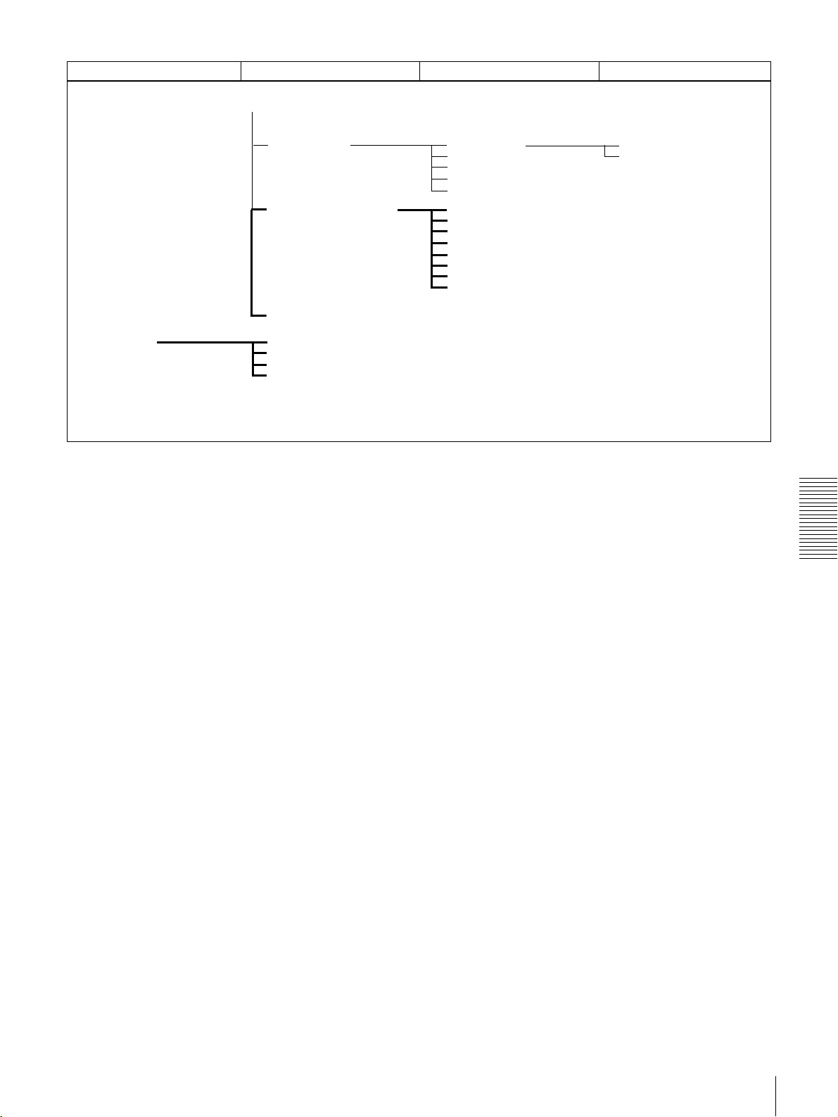
As shown in the following figure, the menu system
consists of four levels and is functionally divided into two
subsystems: the setup menu and the digital hours meter
display menu. This chapter mainly describes the setup
menu, showing its contents and how to operate it.
For details of the digital hours meter display, see “Regular
Checks” (page 59).
The items of the setup menu are divided into several
functional groups on level 1, and except for the MENU
GRADE item the settings themselves are made on level 2
or level 3.
Also, the menu items are divided into two categories
according to how frequently they are accessed: the “basic”
items, to which frequent access is normally required, and
the “enhanced” items, which are less frequently used. In
the following figure, the items shown in boldface are basic
items, and the other items are enhanced items.
The menu settings are saved in non-volatile memory,
which means they are not erased when you power off the
unit after executing the setting operation.
Chapter 4
Menu Organization
35
Page 36

Menu organization
Level 1 Level 2Menu selection level
SETUP MENU
Chapter 4 Menu Settings
OPERATIONAL FUNCTION
DISPLAY CONTROL
TIME CODE
TAPE PROTECTION
VIDEO CONTROL
REPEAT FUNCTION
LOCAL ENABLE
SEARCH ENABLE
MAX SRCH SPEED
JOG RESPONSE
PREROLL TIME
AFTER CUE-UP
PLAY START
AUTO REW
CHARA. DISPLAY
CHARA. POSITION
CHARA. TYPE
CHARA. VSIZE
DISPLAY INFO
MENU DISPLAY
PEAK HOLD
OVER DISP HOLD
BRIGHTNESS
ALARM
REF ALARM
DF MODE
TC SELECT
VITC POS SEL-1
VITC POS SEL-2
VITC OUTPUT
MUTE IN SRCH
FROM STOP
FROM STILL
STILL MODE
SETUP ADD
CC(F1) BLANK
CC(F2) BLANK
WIDE MODE
ESR MODE
PROCESS CONTROL
a)
a)
a)
a)
Level 3
REPEAT MODE
REPEAT TOP
REPEAT END
A PRESET
B PRESET
SHUTTLE
F.FWD/REW
STOP TIMER
STILL TIMER
NEXT MODE
CONTROL DEV
C PHASE MODE
ADJ RANGE
VIDEO GAIN
CHROMA GAIN
CHROMA PHASE
SETUP LEVEL
BLACK LEVEL
a)
b)
36
Menu Organization
(Continued)
a) Menu item for DSR-1600A only
b) Menu item for DSR-1600AP only
Page 37
(Continued)
Level 1 Level 2 Level 3Menu selection level
HOURS METER
AUDIO CONTROL
SETUP BANK OPERATION
MENU GRADE
T1:OPERATION
T2:DRUM ROTATION
T3:TAPE RUNNING
CT:THREADING
LEVEL SELECT
OUTPUT CH3/4
JOG CONTROL
SHUTTLE MUTE
DV PB ATT
RECALL BANK1
RECALL BANK2
RECALL BANK3
RECALL BANK4
SAVE BANK 1
SAVE BANK 2
SAVE BANK 3
SAVE BANK 4
REF LEVEL
OUTPUT LEVEL
Chapter 4 Menu Settings
Menu Organization
37
Page 38
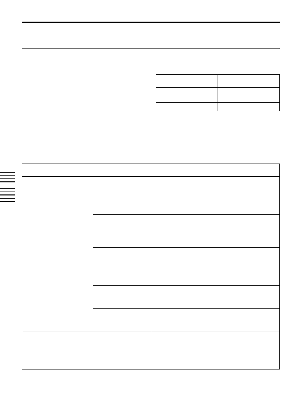
Menu Contents
Setup Menu
The purpose and settings of the setup menu items are
described below.
Indications of menu items and settings
In the table below entitled “Menu contents,” the indication
of each menu item or setting on the monitor screen is
shown first, then the indication of the same item or setting
in the time counter display of this unit is shown in square
brackets ([ ]).
Menu contents
OPERATIONAL FUNCTION [Operational]: Operation
settings
REPEAT FUNCTION [>REP
FUNC]: Make settings for
repeat playback mode.
Chapter 4 Menu Settings
LOCAL ENABLE [> Local ENA]: Select which of the tape
transport control buttons (EJECT, REW, PLAY, F FWD, and
STOP) operate when the REMOTE button is lit.
REPEAT MODE
[>>REPEAT MD]:
Determine whether or
not to put the unit into
repeat playback mode.
REPEAT TOP [>>REP
TOP]: Determine
whether the repeat
start point is the
beginning of tape or
point A.
REPEAT END [>>REP
END]: Determine
whether the repeat end
point is the end of the
video recorded portion,
the end of tape or point
B.
A PRESET [>>A preset]:
Specify a time code
value to be used as the
setting of point A.
B PRESET [>>B preset]:
Specify a time code
value to be used as the
setting of point B.
Examples:
Indication on monitor
screen
OPERATIONAL FUNCTION [Operational]
CASSETTE OUT [>> Cass. out]
*X32
• Settings preceded by an asterisk (such as *
Indication in time counter
display
[>>> X32]
X32) are
factory default settings.
• In the time counter display, one to three “>” symbols
may precede item or setting indications depending on the
current menu level. Larger numbers of “>” symbols
indicate lower menu levels.
Description of settings
*OFF [>>> OFF]: Do not put the unit into repeat playback
mode.
ON [>>> ON]: Put the unit into repeat playback mode.
ON (FREEZE) [>>> FREEZE]: Put the unit into freeze
playback mode. In this case, while the unit is cueing up to
the repeat start point, the freeze picture of the repeat end
point is displayed.
*TAPE TOP [>>>Tape top]: The repeat start point is the
beginning of tape.
A POINT [>>>A point]: The repeat start point is point A as set
by the user.
*VIDEO END [>>>VD end]: The repeat end point is the end
of the video recorded portion.
TAPE END [>>>Tape end]: The repeat end point is the end of
tape.
B POINT [>>>B point]: The repeat end point is point B as set
by the user.
For details, see “Setting Points A and B for Repeat Playback”
on page 24.
For details, see “Setting Points A and B for Repeat Playback”
on page 24.
ALL DISABLE [>> All DIS]: All of the tape transport control
buttons are disabled.
*STOP & EJECT [>> STOP & EJ]: Only the STOP and
EJECT buttons are enabled.
ALL ENABLE [>> All ENA]: All of the tape transport control
buttons are enabled, and settings such as preroll time
change or time data display selection are effective.
38
Menu Contents
Page 39

OPERATIONAL FUNCTION [Operational]: Operation
settings
SEARCH ENABLE [>Search ENA]: Select how the unit enters
the search mode.
MAX SRCH SPEED [>Max
SRCH]: Specify the
maximum tape speed in
search mode (shuttle) and
F.FWD (fast forward)/REW
(rewind) mode.
SHUTTLE [>>SHUTTLE]:
Specify the maximum
tape speed in search
mode (shuttle).
F.FWD/REW [>>F.FWD/
REW]: Specify the
maximum tape speed
in F.FWD/REW mode.
JOG RESPONSE [>JOG dial]: Select the tape speed
characteristics for the search dial rotation rate in jog mode.
Description of settings
*DIAL DIRECT [>> DIAL]: Press the SEARCH button or,
except during editing, turn the search dial.
VIA SEARCH KEY [>> via KEY]: Press the SEARCH button.
X60 [>>> X60]: Maximum 60 times normal speed
*X32 [>>> X32]: Maximum 32 times normal speed
X16 [>>> X16]: Maximum 16 times normal speed
MAX [>>> MAX]: No maximum tape speed is specified.
*X85 [>>> X85]: Maximum 85 times normal speed
X60 [>>> X60]: Maximum 60 times normal speed
X32 [>>> X32]: Maximum 32 times normal speed
Note
When this item is set to MAX, the playback video signal is
muted.
*TYPE1 (–1 to +1) [>> type 1]: Tape speed varies linearly
over the range −1 to +1.
TYPE2 (–3 to +3) [>> type 2]: Tape speed varies stepwise as
shown in the figure below over the range −3 to +3.
(Characterized by a zone around −1 and +1 where the
tape speed is independent of the rotation rate)
TYPE3 (–3 to +3) [>> type 3]: Tape speed varies linearly over
the range −3 to +3, as shown in the figure below.
TYPE2
RVS
RVS
+3
+1
Speed
FWD
-1
-3
Rotation rate
FWD
TYPE3
RVS
RVS
+3
Speed
FWD
Rotation rate
FWD
-3
PREROLL TIME [> Preroll]: Set the preroll time. 0 SEC [>> 0 sec] to 15 SEC [>> 15 sec]: The preroll time
can be set in one-second increments to between 0 and 15
seconds.
A preroll time of at least 5 seconds is recommended when
using this unit for editing. When an editing control unit such as
the PVE-500 has been connected, this setting is disabled and
the setting on the editing control unit is in effect. Operations
such as the preroll time setting and the time data switching
operation are also performed on the editing control unit.
Factory default setting: 5 SEC [>> 5 sec]
AFTER CUE-UP [> After CUE]: Select the operating mode
following cue-up.
PLAY START [> PLAY start]: Set the timing for switching from
stop mode to playback mode.
In an editing system including an editing control unit such as
the PVE-500, you can adjust this setting so that the delay
before switching to playback mode is the same on all the decks
of the editing system. It is then no longer necessary to
synchronize the decks for editing, and the preroll time can be
shortened.
AUTO REW [>Auto REW]: Select whether to rewind the tape
automatically when recording or playback reaches the end
of a tape.
*STOP [>> STOP]: Stop mode
STILL [>> STILL]: Output still pictures in search mode.
16 FRAME DELAY [>> 16 delay] to 4 FRAME DELAY [>> 4
delay]: The larger the numerical value, the longer the
delay. By adjusting this setting, it is possible to reduce the
phase synchronization time and preroll time during
editing.
Factory default setting: 5 FRAME DELAY [>> 5 delay] (for
DSR-1600A) or 4 FRAME DELAY [>> 4 delay] (for DSR1600AP)
DISABLE [>> DISABLE]: Do not rewind the tape
automatically.
*ENABLE [>> ENABLE]: Rewind the tape automatically.
Chapter 4 Menu Settings
Menu Contents
39
Page 40

DISPLAY CONTROL [Display]: Settings related to
indications on the monitor and the unit
CHARA. DISPLAY [> Chara disp]: Determine whether or not
to output text (such as time code values) from the VIDEO
OUT 2 (SUPER) connector.
CHARA. POSITION [> Chara pos]: Set the position of text
superimposed on output from the VIDEO OUT 2 (SUPER)
connector to the monitor.
CHARA. TYPE [> Chara type]: Set the type of characters in
text superimposed on output from the VIDEO OUT 2
(SUPER) connector to the monitor.
CHARA. VSIZE [> Chara size]: Determine the vertical size of
characters such as time code output from the VIDEO OUT
2 (SUPER) connector for superimposed display on the
monitor.
DISPLAY INFO [> DISP info]: Select information
superimposed on output from the VIDEO OUT 2 (SUPER)
connector to the monitor.
Chapter 4 Menu Settings
MENU DISPLAY [> Menu DISP]: Set the type of characters in
menu text superimposed on output from the VIDEO OUT 2
(SUPER) connector to the monitor.
PEAK HOLD [>Peak hold]: Set the peak hold time for the
audio level meters.
OVER DISP HOLD [> Hold OVER]: Determine whether or not
to hold the OVER indication display on the audio level
meters once the indications light.
BRIGHTNESS [> Brightness]: Set the brightness of front
panel indicators.
Description of settings
OFF [>> OFF]: Do not output text. (In spite of this setting,
pressing the MENU button causes menu text to be
output.)
*ON [>> ON]: Output text.
JjKk buttons on the menu control panel to adjust the
Use
text position while watching the monitor screen.
To return to the level 1 of the setup menu, press the MENU
button.
Make the following settings while watching the monitor screen.
*WHITE (WITH BKGD) [>> White]: White characters on black
background
BLACK (WITH BKGD) [>> Black]: Black characters on white
background
WHITE/OUTLINE [>> W/outline]: White characters with black
outline
BLACK/OUTLINE [>> B/outline]: Black characters with white
outline
*×1 [>> ×1]: Standard size
×2 [>> ×2]: 2 times standard size
*TIME DATA & STATUS [>> Time&STA]: Time data and
operating mode indications
TIME DATA & UB [>> Time&UB]: Time data selected using
the COUNTER SEL button, and user bit data (When user
bit data is selected using the COUNTER SEL button, user
bit data and time code are shown.)
TIME DATA & CNT [>> Time&CNT]: Time data selected
using the COUNTER SEL button, and CNT value (When
CNT is selected using the COUNTER SEL button, CNT
value and time code are shown.)
TIME DATA & TIME[>> Time&Time]: Time data and VITC
TIME DATA ONLY [>> Time]: Time data only
REC DATE & TIME [>> REC Date]: The time data selected
with the COUNTER SEL button is shown in the time
counter display, and the date and time of recording are
shown on the monitor screen.
Make the following settings while watching the monitor screen.
*WHITE (WITH BKGD) [>> White]: White characters on black
background
BLACK (WITH BKGD) [>> Black]: Black characters on white
background
WHITE/OUTLINE [>> W/outline]: White characters with black
outline
BLACK/OUTLINE [>> B/outline]: Black characters with white
outline
OFF [>> OFF] to 1.5 SEC [1.5 sec]: Set the peak hold time in
the range of OFF (no peak hold) to 1.5 seconds in 0.1
second steps.
Factory default setting: OFF [>> OFF]
*OFF [>> OFF]: Do not hold the OVER indication display.
ON (HOLD) [>> ON]: Hold the OVER indication display.
Note
With ON selected, once the display is held it will remain held
unless you change the setting to OFF.
Set brightness as a percentage of the maximum.
100% [>> 100%]
*75% [>> 75%]
50% [>> 50%]
40
Menu Contents
Page 41

DISPLAY CONTROL [Display]: Settings related to
indications on the monitor and the unit
ALARM [> ALARM]: Determine whether alarm messages are
issued or not.
REF ALARM [> REF ALARM]: Determine whether alarm
messages related to reference video signal are issued or
not.
Description of settings
OFF [>> OFF]: Alarm messages are not issued.
*ON [>> ON]: Alarm messages are issued.
*OFF [>> OFF]: Alarm messages are not issued.
ON [>> ON]: Alarm messages are issued.
TIME CODE [Time code]: Settings related to the time code
generator
(For DSR-1600A only)
DF MODE [> DF mode]: Select whether the time counter
operate in drop frame mode or non-drop frame mode.
Normally select drop frame mode, to keep in
synchronization with real time. The non-drop frame mode
is useful for example when using computer graphics, and
working on a frame count basis.
TC SELECT [>TC select]: Determine which to display in the
time counter display, TC or VITC.
VITC POS SEL-1 [>VITC pos-1]: Select a line to insert the
VITC in.
Note
You can insert the VITC signal in two places. To insert it in two
places, set both this item and also VITC POS SEL-2.
VITC POS SEL-2 [>VITC pos-2]: Select a line to insert the
VITC in.
Note
You can insert the VITC signal in two places. To insert it in two
places, set both this item and also VITC POS SEL-1.
VITC OUTPUT [>VITC out]: Select the time code to be output
as VITC.
MUTE IN SRCH [>Mute in SR]: Select whether to mute the
output from the TIME CODE OUT connector in search
(jog/shuttle) mode.
Description of settings
*ON (DF) [>> ON (DF)]: Drop frame mode
OFF (NDF) [>> OFF (NDF)]: Non-drop frame mode
VITC [>> VITC]: Display VITC.
*TC [>> TC]: Display TC.
(For DSR-1600A)
12 LINE [>> 12 line] to 20 LINE [>> 20 line]: Select any line
from 12 to 20.
Factory default setting: 16 LINE [>> 16 line]
(For DSR-1600AP)
Select a line to insert the VITC in.
9 LINE [>> 9 line] to 22 LINE [>> 22 line]: Select any line
from 9 to 22.
Factory default setting: 19 LINE [>> 19 line]
(For DSR-1600A)
12 LINE [>> 12 line] to 20 LINE [>> 20 line]: Select any line
from 12 to 20.
Factory default setting: 18 LINE [>> 18 line]
(For DSR-1600AP)
Select a line to insert the VITC in.
9 LINE [>> 9 line] to 22 LINE [>> 22 line]: Select any line
from 9 to 22.
Factory default setting: 21 LINE [>> 21 line]
OFF [>> OFF]: Do not output VITC.
TC [>> TC]: Output TC after converting it into VITC.
*VITC [>> VITC]: Output VITC.
OFF [>> OFF]: Do not mute.
*ON [>> ON]: Mute.
Chapter 4 Menu Settings
TAPE PROTECTION [Tape protct]: Settings related to tape
and video head protection
FROM STOP [> From STOP]:
Set the time to switch from
stop mode to tape protection
mode.
STOP TIMER [>> STP
timer]: Set the time to
switch from stop mode
to tape protection
mode.
Description of settings
5 MIN [>>> 5 min] to 0.5 SEC [>>> 0.5 sec]: Select time from
12 settings ranging from 0.5 second to 5 minutes in steps
of 0.1 second.
Factory default setting: 1MIN [>>> 1min]
Note
If the value is set to 1 minute or more, the unit enters internal
protection mode in 1 minute, which makes start up slower.
Menu Contents
41
Page 42

TAPE PROTECTION [Tape protct]: Settings related to tape
Description of settings
and video head protection
FROM STILL [> From STILL]:
Set the time to switch from
still search mode to tape
protection mode. Also select
the type of tape protection
mode.
STILL TIMER [>> STL
timer]: Set the time to
switch from still search
mode to tape
protection mode.
5 MIN [>>> 5 min] to 0.5 SEC [>>> 0.5 sec]: Select time from
12 settings ranging from 0.5 second to 5 minutes in steps
of 0.1 second.
Factory default setting: 1MIN [>>> 1min]
Note
If the value is set to 1 minute or more, the unit enters internal
protection mode in 1 minute, which makes start up slower.
NEXT MODE [>> Next
mode]: Select the type
of tape protection
mode to follow still
search mode when the
time set with the STILL
TIMER menu item
elapses.
*STEP FWD [>>> Step]: The tape is advanced at
normal speed for about 2 seconds.
STANDBY OFF [>>> STANDBY]: Standby off mode
Note
The STEP setting is enabled only when “STILL TIMER” is set
to less than 1 minute.
VIDEO CONTROL [Video]: Settings related to video control Description of settings
STILL MODE [> STILL mod]: Select the image to output in
still image mode.
*AUTO [>> Auto]: Output field 1 or field 2 as the still image,
according to the position the tape is stopped.
FRAME [>> Frame]: Output a full frame as the still image.
FIELD1 [>> Field 1]: Output only field 1 as the still image.
FIELD2 [>> Field 2]: Output only field 2 as the still image.
(For DSR-1600A only)
SETUP ADD [> Setup add]: Determine whether or not to add
*OFF [>> OFF]: Do not add black setup.
ON (ADD) [>> ON]: Add black setup.
black setup to analog video output signals.
(For DSR-1600A only)
CC(F1) BLANK [>CC1 blank]: Select whether to mute the
*OFF [>> OFF]: Do not mute.
ON [>> ON]: Mute.
closed caption signal to be superimposed on the 1st field
Chapter 4 Menu Settings
of the output video signal.
(For DSR-1600A only)
CC(F2) BLANK [>CC2 blank]: Select whether to mute the
*OFF [>> OFF]: Do not mute.
ON [>> ON]: Mute.
closed caption signal to be superimposed on the 2nd field
of the output video signal.
WIDE MODE [>Wide mode]: Determine whether to retain
wide-screen aspect ratio information accompanying video
being played back.
*AUTO [>> Auto]: When video being played back is
accompanied by wide-screen aspect ratio information,
retain the information.
OFF [>> OFF]: Ignore wide-screen aspect ratio information.
ON [>> ON]: Whenever recording or playing back video, retain
wide-screen aspect ratio information.
ESR MODE [>ESR mode]: Select whether to enable the edge
subcarrier reducer (ESR).
*OFF [>> OFF]: Do not enable.
ON [>> ON]: Enable.
When playing back a composite signal, set this to ON.
1
/30 times
42
Menu Contents
Page 43
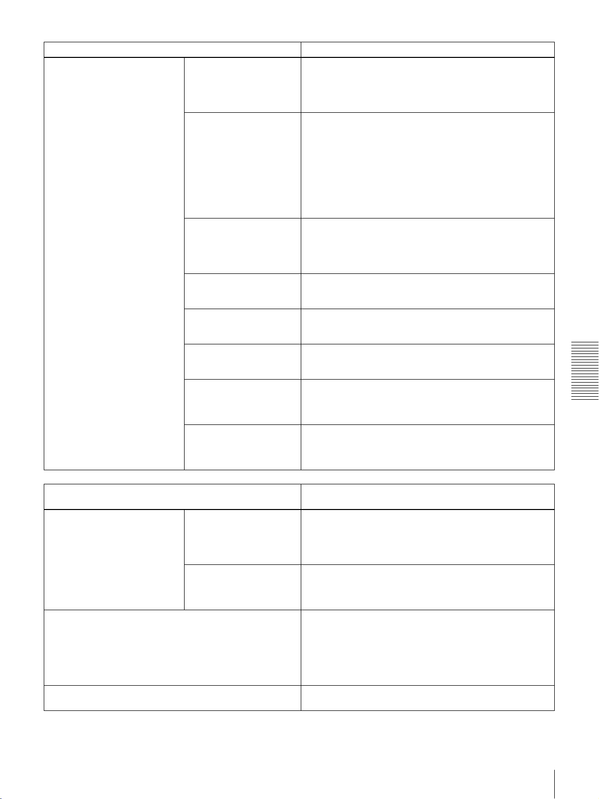
VIDEO CONTROL [Video]: Settings related to video control Description of settings
PROCESS CONTROL [>Proc
ctrl]
CONTROL DEV [>>Ctrl
dev]: Select the
method of controlling
the internal digital
video processor.
C PHASE MODE [>>C
Phas MD]: Select the
phase rotation mode
for chroma phase
control.
The effect of this setting
applies to the output levels
of all of the composite
video, S video, SDI and
component video signals.
ADJ RANGE [>>Adj
range]: Select the
variable range of the
VIDEO and CHROMA
gains.
VIDEO GAIN [>>V gain]:
Adjust the video output
level.
CHROMA GAIN [>>C
gain]: Adjust the
chroma output level.
CHROMA PHASE [>>C
phase]: Adjust the
chroma phase.
(For DSR-1600A only)
SETUP LEVEL [>>Setup
lev]: Adjust the black
setup level.
(For DSR-1600AP only)
BLACK LEVEL [>>Black
lev]: Adjust the black
level.
*REMOTE [>>>REMOTE]: Use an optional remote control
unit to control the internal digital video processor.
MENU [>>> MENU]: Use the setup menu to change the
settings for the internal digital video processor.
*U/V (COMPOSITE) [>>> Cmpst]: Select this setting when
observing the composite video output level using a
composite vectorscope.
PB/PR (COMPONENT) [>>> Cmpnt]: Select this setting
when observing the component video output level using a
component vectorscope.
*−3 to +3 (dB) [>>> −3/+3]: −3 dB to +3 dB
WIDE [>>> wide]: −∞ to +3 dB
00H to 3FFH
Factory default setting: 200H
00H to 3FFH
Factory default setting: 200H
00H to FFH
Factory default setting: 80H
00H to 3FFH
Factory default setting: 200H
00H to 3FFH
Factory default setting: 200H
Chapter 4 Menu Settings
AUDIO CONTROL [Audio]: Settings related to audio
control
LEVEL SELECT [>Level Sel] REF LEVEL [>>REF
Level]: Select the
audio reference level
(headroom).
OUTPUT LEVEL [>>Out
Level]: Select the
analog audio output
reference level.
OUTPUT CH3/4 [>OUT ch3/4]: Select the signals to be output
from the AUDIO OUT CH-3 and AUDIO OUT CH-4
connectors.
JOG CONTROL [> Jog ctrl]: Select whether to adjust the
audio playback speed during slow playback.
Description of settings
*−20 dB [>>> −20dB] (factory default setting for DSR-1600A)
*−18 dB [>>> −18dB] (factory default setting for DSR-
1600AP)
−16 dB [>>> −16dB]
−12 dB [>>> −12dB]
*+4 dBm [>>> +4dBm]
0 dBm [>>> 0dBm]
−3 dBm [>>> −3dBm] (for DSR-1600AP only)
−6 dBm [>>> −6dBm]
*LINE OUT [>> line out]: Output the audio channel-3 and
audio channel-4 signals from the AUDIO OUT CH-3 and
AUDIO OUT CH-4 connectors as they are.
MONITOR OUT [>> monitor]: Output the monitor audio L-
channel (CH-1) and monitor audio R-channel (CH-2)
signals from the AUDIO OUT CH-3 and AUDIO OUT CH4 connectors, respectively.
OFF [>> OFF]: Do not adjust the audio playback speed.
*ON [>> ON]: Adjust the audio playback speed.
Menu Contents
43
Page 44

AUDIO CONTROL [Audio]: Settings related to audio
control
SHUTTLE MUTE [>Shutl mute]: Set the audio muting
conditions during shuttle playback.
DV PB ATT [>DV PB ATT]: When playing back a tape
recorded in consumer DV format, select whether to
attenuate the audio output level.
Description of settings
*OFF [>> OFF]: Not muted.
CUEUP or PREROLL [>> CUEUP]: Muted during cue-up or
preroll operations.
FULL [>> FULL]: Muted in shuttle mode.
OFF [>> OFF]: Do not attenuate.
*ON [>> ON]: Attenuate.
SETUP BANK OPERATION [Setup Bank]: Settings related
to menu bank operations
RECALL BANK1 [>Recall 1]: Recall menu settings from
menu bank 1.
RECALL BANK2 [>Recall 2]: Recall menu settings from
menu bank 2.
RECALL BANK3 [>Recall 3]: Recall menu settings from
menu bank 3.
RECALL BANK4 [>Recall 4]: Recall menu settings from
menu bank 4.
SAVE BANK 1 [>Save 1]: Save current menu settings to menu
bank 1.
SAVE BANK 2 [>Save 2]: Save current menu settings to menu
bank 2.
SAVE BANK 3 [>Save 3]: Save current menu settings to menu
bank 3.
SAVE BANK 4 [>Save 4]: Save current menu settings to menu
bank 4.
Menu banks
Chapter 4 Menu Settings
This unit allows four different complete sets of menu settings to be saved in what are termed “menu banks” numbered 1 to 4.
Saved sets of menu settings can be recalled for use as required.
MENU GRADE [Menu grade]: Selection of menu items to
be displayed
Determine whether to display basic items only or both basic
and enhanced items on the monitor screen and in the time
counter display when using the menu.
Description of settings
(1) Select the bank you want to recall, then press the k
button.
Message “RECALL OK?” appears.
(2) To recall, press the SET (YES) button.
To quit recalling, press the RESET (NO) button.
(1) Select the bank you want to save, then press the k
button.
Message “SAVE OK?” appears.
(2) To save, press the SET (YES) button.
To quit saving, press the RESET (NO) button.
Description of settings
*BASIC [> Basic]: Display basic items only.
ENHANCED [> Enhanced]: Display both basic and enhanced
items.
44
Menu Contents
Page 45

Changing Menu Settings
Changing the Settings of Basic Items
This section explains how to change menu settings.
Buttons Used to Change Settings
Use the following buttons on the menu control panel to
change the menu settings.
Menu control buttons Functions
MENU button • Opens the menu and
launches menu control
mode.
• Closes the menu and exits
menu control mode.
J and j buttons These buttons move the
highlighted cursor up and
down within the current level
to select an item or setting.
Hold down one of these
buttons to make the
highlighted cursor move
continuously.
K and k buttons • Press the k button to go
down one level.
• Press the K button to go
up one level.
Hold down one of these
buttons to make the
highlighted cursor move
continuously.
RESET (NO) button • Returns the setting to the
factory default setting.
• Sends a negative
response to prompts on
the monitor screen.
SET (YES) button • Saves the new setting in
memory.
• Sends a positive response
to prompts on the monitor
screen.
The factory default setting is to display only the basic
items. To change the settings of basic items proceed as
follows.
1
3,5,7
2,4,6
A B
MARK
9
8
1 Press the MENU button on the menu control panel.
The menu selection level display appears on the
monitor. In the figure below, “SETUP MENU” is
selected (shown in reverse video).
The time counter display of this unit shows only the
currently selected item. When the item name is long, it
is abbreviated.
Menu selection level display
SYSTEM MENU
SETUP MENU
HOURS METER
Setup menu
Time counter display
Chapter 4 Menu Settings
Monitor screen
Changing Menu Settings
45
Page 46

2 With “SETUP MENU” selected, press the k button.
This displays all items on menu level 1.
Level-1 menu display
OPERATIONAL FUNCTION
SETUP MENU
DISPLAY CONTROL
TIME CODE
SETUP BANK OPERATION
MENU GRADE :BASIC
Monitor screen
Operational
Time counter display
3 Press the J or j button to select the required item.
Example: Display when “DISPLAY CONTROL” is selected
5 Press the J or j button to select the item whose
setting you wish to change.
For menu items on level 3, press the k button to go
to the level 3, then press the J or j button to select the
item whose setting you wish to change.
Example: Display when “BRIGHTNESS” is selected
DISPLAY CONTROL
SETUP MENU
CHARA.DISPLAY
CHARA.POSITION
CHARA.TYPE
CHARA.VSIZE
DISPLAY INFO
MENU DISPLAY
PEAK HOLD
OVER DISP HOLD
BRIGHTNESS
ALARM
Monitor screen
:ON
:WHITE
:x1
:T&STA
:WHITE
:OFF
:OFF
:75%
:ON
> Brightness
Time counter display
OPERATIONAL FUNCTION
SETUP MENU
DISPLAY CONTROL
TIME CODE
SETUP BANK OPERATION
MENU GRADE :BASIC
Chapter 4 Menu Settings
Monitor screen
4 Press the k button.
This displays the menu level 2 for the menu item
selected in step 3.
Example: Level-2 display for “DISPLAY CONTROL”
SETUP MENU
DISPLAY CONTROL
CHARA.DISPLAY
CHARA.POSITION
CHARA.TYPE
CHARA.VSIZE
DISPLAY INFO
MENU DISPLAY
PEAK HOLD
OVER DISP HOLD
BRIGHTNESS
ALARM
:ON
:WHITE
:x1
:T&STA
:WHITE
:OFF
:OFF
:75%
:ON
Display
Time counter display
> Chara disp
Time counter display
Current settings
6 Press the k button.
This displays all possible settings for the item selected
in step 5.
DISPLAY CONTROL
SETUP MENU
BRIGHTNESS
100%
* 75%
50%
Monitor screen
:75%
>> 75%
Time counter display
7 Press the J or j button to change the setting of the
item.
DISPLAY CONTROL
SETUP MENU
BRIGHTNESS
100%
* 75%
50%
:75%
>> 50%
Time counter display
Changing Menu Settings
46
Monitor screen
Monitor screen
Page 47

8 To change other settings, press the K button to return
to the previous screen, then repeat steps 5 to 7 as
required.
9 When you have completed the settings, press the SET
(YES) button.
The message “NOW SAVING...” appears on the
monitor screen, and “Saving...” appears in the time
counter display, while the new settings are saved in
memory.
When the saving operation is completed, the monitor
screen and time counter display return to their normal
indications.
Displaying Enhanced Items
The factory default setting is not to display enhanced
items.
To display enhanced items, set the MENU GRADE menu
item (see page 44) to ENHANCED, following the
procedure in the previous section “Changing the Settings
of Basic Items.” (In step 3, first select “MENU GRADE,”
and next select “ENHANCED,” then press the SET (YES)
button to save the setting in memory.)
With this done, when you press the MENU button and the
k button to display the setup menu, all basic and
enhanced items in the menu level 1 appear.
Notes
• If you power off the unit before saving operation is
completed, settings may be lost. Wait until the
saving is completed before powering off the unit.
• If, instead of pressing the SET (YES) button, you
press the MENU button, the new settings are not
saved. The message “ABORT!” appears on the
monitor screen and “Abort!” in the time counter
display for about 0.5 second, and the system exits
the menus. To change more than one setting, be sure
to press the SET (YES) button after making the
settings.
Meanings of indications on the monitor
screen
On-screen indication Meaning
Right-pointing arrow (k) at
the right of a menu item
See step 1 of the foregoing
operating procedure.
Left-pointing arrow (K) at
the left of a menu item
See step 4 of the foregoing
operating procedure.
Character string at the right of
a menu item
See step 4 of the foregoing
operating procedure.
An asterisk in a complete list
of settings
See step 6 of the foregoing
operating procedure.
Pressing the k button
switches to the next lower
menu level or to a setting
selection screen.
Pressing the K button
returns to the previous
(higher) menu level.
Current setting of the menu
item.
• When shown with a colon
(:): the current setting is
the same as the factory
default setting.
• When shown with a raised
dot (•): the current setting
is different from the factory
default setting.
See step 2 of the operating
procedure in “Changing the
Settings of Enhanced Items”
on page 47.
Factory default setting.
Changing the Settings of Enhanced Items
To change the settings of enhanced items, first carry out
the procedure in the previous section “Displaying
Enhanced Items,” then proceed as follows.
3
2
MARK
4
1
A B
1 Press the MENU button on the menu control panel.
The menu selection level display appears on the
monitor.
2 With “SETUP MENU” selected, press the k button.
This displays all basic and enhanced items on menu
level 1.
Level-1 menu display
OPERATIONAL FUNCTION
DISPLAY CONTROL
TIME CODE
TAPE PROTECTION
VIDEO CONTROL
AUDIO CONTROL
SETUP BANK OPERATION
MENU GRADE
SETUP MENU
ENHAN
Monitor screen
Menu grade
Time counter display
Current setting
Chapter 4 Menu Settings
Changing Menu Settings
47
Page 48
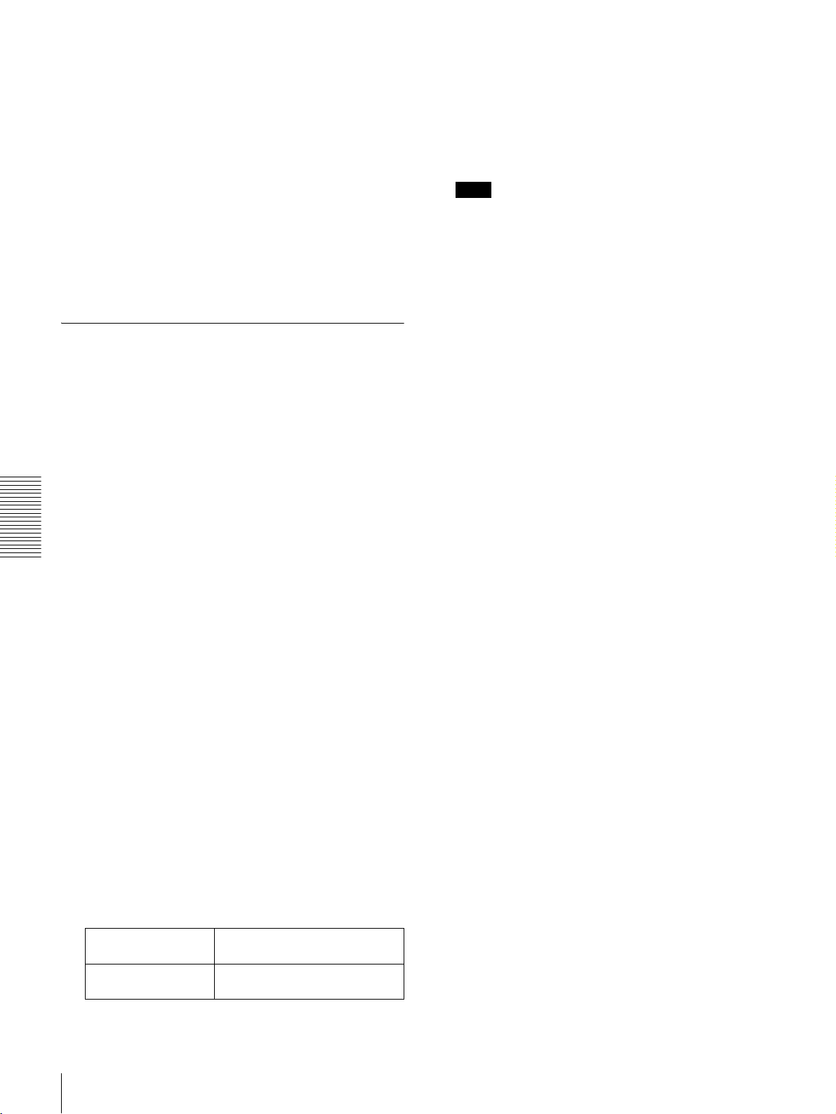
3 Follow the same procedure as in steps 3 to 8 of the
procedure in the section “Changing the Settings of
Basic Items” on page 45 using the arrow buttons to
select an item and change its setting.
4 When you have completed the settings, press the SET
(YES) button.
4 Press the SET (YES) button.
The message “NOW SAVING...” appears on the
monitor screen, and “Saving...” appears in the time
counter display, while the settings of all items are
returned to their factory default settings. These factory
default settings are saved in memory.
The message “NOW SAVING...” appears on the
monitor screen, and “Saving...” appears in the time
counter display, while the new settings are saved in
memory.
When the saving operation is completed, the monitor
screen and time counter display return to their normal
indications.
Returning Menu Settings to Their Factory Default Settings
After making menu setting changes, to return settings to
their factory default settings (setting initialization), use the
following procedure.
To return a particular setting to its factory
default setting
In the display for changing the target setting, press the
RESET (NO) button.
Carry out the procedure in the section “Changing the
Settings of Basic Items” on page 45 up to step 6, then with
Chapter 4 Menu Settings
the current setting displayed (in the example, if the setting
has been changed it will be “100%” or “50%”), press the
RESET (NO) button. The setting returns to its factory
default setting of “75%.”
Note
If you power off the unit while settings are being
saved, settings may not be correctly returned to their
factory default settings. Wait until the saving is
completed before powering off the unit.
To abandon the resetting operation
Instead of pressing the SET (YES) button, press the
RESET (NO) button.
The display returns to menu level 1, leaving the
settings unchanged.
To return all settings to their factory
default settings
Use the following procedure.
1 Press the MENU button on the menu control panel to
display the menu selection.
2 Press the k button to display level 1 of the setup
menu.
3 Press the RESET (NO) button.
A message appears, to confirm whether or not you
wish to return all settings to their factory default
settings.
Monitor screen
message
Message in the time
counter display
“INITIALIZE ALL ITEMS TO
FACTORY PRESET VALUES?”
“Init setup?”
Changing Menu Settings
48
Page 49

Connections and
Settings
Note
Production of some of the peripherals and related devices
described in this chapter has been discontinued. For advice
about choosing devices, please contact your Sony dealer or
a Sony sales representative.
Chapter 5
Connections for a Digital Non-Linear Editing System
This unit can be connected to a nonlinear editor supporting
DV/DVCAM with an i.LINK cable (DV cable).
Shown below is an example of connections to use this unit
as a player in a nonlinear editing system.
Notes
• Refer to the documentation of your nonlinear editing
equipment and software for more information about
connection and settings on the nonlinear editing
equipment.
• Different editing software applications provide different
editing functions. For more information about actual
editing procedures and settings, refer to the
documentation of your editing software.
DV IN/OUT
DSR-1600A/1600AP
Composite
video input
VIDEO OUT 2
(SUPER)
23
Audio input
Video monitor
1
Nonlinear editing system
AUDIO
MONITOR OUT
A i.LINK cable (DV cable)
(not supplied)
B 75 Ω coaxial cable (not supplied)
C Cable with RCA phono plugs
(not supplied)
Connections for a Digital Non-Linear Editing System
49
Page 50

Settings on the DSR-1600A/1600AP
Button Setting
REMOTE On (lit)
9PIN Off (unlit)
i.LINK On (lit)
Notes
• When you connect this unit to another device with a 6pin DV connector, always power the other device off and
unplug its power cord from the power output before
connecting or disconnecting the i.LINK (DV cable). If
you connect or disconnect the cable with the power cord
still plugged in, power from the DV connector may flow
into this unit, possibly damaging this unit.
• When you connect this unit to another device with a 6pin DV connector, make the connection to the 6-pin DV
connector on the other device before making the
connection to this unit.
Chapter 5 Connections and Settings
Connections for a Digital Non-Linear Editing System
50
Page 51
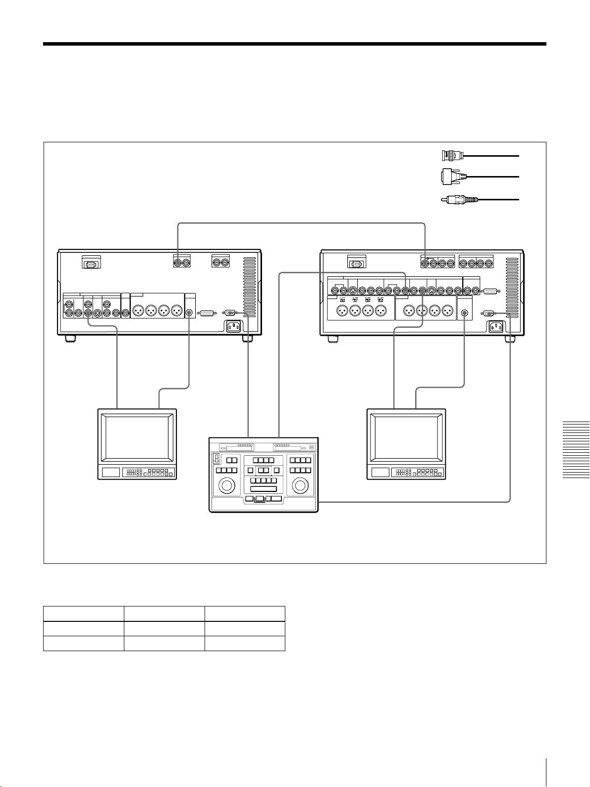
Connections for a Cut Editing System
The following figure shows a cut editing system
configuration which includes a DSR-1600A/1600AP unit
as the player and a DSR-1800A/1800AP as the recorder.
DSR-1600A/
1600AP (player)
VIDEO
OUT 2
(SUPER)
1321 132
Composite
video input
MONITOR
SDI OUT
AUDIO
REMOTE
OUT
Audio input
For details of connecting devices other than the DSR1600A/1600AP, refer to the instruction manual for each
device.
A 75 Ω coaxial cable (not supplied)
B 9-pin remote control cable
(not supplied)
C Cable with RCA phono plugs
(not supplied)
1
DSR-1800A/
1800AP (recorder)
REMOTE
OUT
REF.
VIDEO
OUT
VIDEO
OUT 2
(SUPER)
Composite
video input
SDI IN
AUDIO
MONITOR
Audio input
PLAYER
Source monitor
Editing control unit (PVE-500, etc.)
Settings on the DSR-1600A/1600AP (player) and
DSR-1800A/1800AP (recorder)
Button Recorder Player
REMOTE On (lit) On (lit)
9PIN On (lit) On (lit)
For details of the video/audio input and audio mode
settings for the recorder, refer to the DSR-1800A/1800AP
Operating Instructions.
REF.
VIDEO IN
Main monitor
RECORDER
a)
a) For the settings on the editing control unit, see
“Settings on an editing control unit” on page
56.
About reference video signals
In order to provide stable video and audio signals for
analog editing, it is necessary for the built-in time base
corrector (TBC) to operate correctly. To ensure this, input
a reference video signal synchronized with the video signal
to the REF. VIDEO IN connector.
Chapter 5 Connections and Settings
Connections for a Cut Editing System
51
Page 52
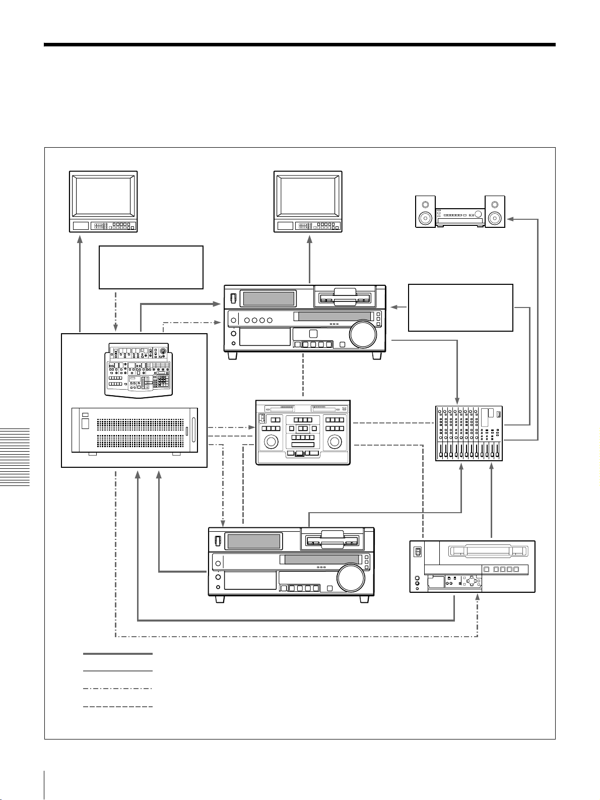
Connections for an A/B Roll Editing System
The following is an example configuration of A/B roll
editing system using the DSR-1600A/1600AP.
Main video monitor
Video signal generator
The purpose of the following figure is to clearly indicate
the flow of signals among the component devices in this
system. The specific connections and settings are
described beginning on page 53.
Source video monitor
DSR-1800A/
1800AP (recorder)
Audio system monitor
DPS-D7 or other delay
a)
unit
Audio mixer
(MXP-290, etc.)
DME switcher
Chapter 5 Connections and Settings
(DFS-500/500P,
etc.)
Video signal
Audio signal
Reference video signal
Control signal
Editing control unit
(PVE-500, etc.)
DSR-1600A/1600AP (player 1)
a) An I/O delay of several frames occurs on DME switchers and other
devices equipped with frame memory. It is therefore necessary to
connect an audio delay unit between the audio mixer and the recorder
VCR to adjust for the delay.
UVW-1600/1600P,
etc. (player 2)
Connections for an A/B Roll Editing System
52
Page 53

Audio monitor system connections
The following shows an example of audio monitor system
connections.
Reference video signal connection
When you perform recording, be sure to input a reference
video signal.
For details of these connections, refer to the instruction
manual for each connected device.
Speaker (left channel)
Audio amplifier
L
MONITOR
OUT 2
MONITOR
OUT 1
R
L
Cables with RCA phono plugs
Speaker (right channel)
R
For details of reference video signals, see “About
reference video signals” on page 51.
DME switcher
(DFS-500/500P, etc.)
BLACK
BURST
OUT
REF. VIDEO IN
1234
REF. VIDEO IN
DSR-1800A/
1800AP (recorder)
DSR-1600A/
1600AP (player 1)
Audio mixer (MXP-290, etc.)
REF. VIDEO IN 75 Ω
termination switch: ON
REF. VIDEO IN
REF.
VIDEO
IN
REF. VIDEO IN 75 Ω termination switch: ON
Use 75 Ω coaxial cables for all of these connections.
UVW-1600/1600P,
etc. (player 2)
Editing control unit
(PVE-500, etc.)
Chapter 5 Connections and Settings
Connections for an A/B Roll Editing System
53
Page 54

Control signal connections
The following shows an example of control signal
connections to enable the editing control unit to control all
other A/B roll editing system devices.
9-pin remote control cable
(not supplied)
DSR-1800A/1800AP
DSR-1800A/1800AP (recorder)
REMOTE
DSR-1600A/1600AP (player 1)
Editing control unit
(PVE-500, etc.)
Chapter 5 Connections and Settings
Mixer control mode
selection switch:
PARALLEL
SWITCHER PLAYER 2MIXER
9-pin remote control cable (not supplied)
RECORDER
9-pin remote control cable
PLAYER 1
(not supplied)
REMOTE
UVW-1600/1600P (player 2)
REMOTE
DME switcher
(DFS-500/500P, etc.)
EDITOR
Audio mixer
(MXP-290, etc.)
Connections for an A/B Roll Editing System
54
9-pin/15-pin mixer control cable (not supplied)
EDITOR (15-pin)
Page 55

Video/audio signal connections
The following shows an example of video/audio signal
connections in an A/B roll editing system.
In this example, analog component signals are used as the
video signals and XLR 3-pin connectors are used as audio
input/output connectors.
DSR-1800A/
1800AP (recorder)
AUDIO IN
CH-1
LINE OUT 2 LINE OUT 1
Audio mixer
(MXP-290, etc.)
COMPONENT VIDEO IN
Y, R–Y, B–Y
CH-2
3
DPS-D7 or other delay unit
3
3
IN
3
1
PGM OUT
COMPONENT 1
CH-2 OUTCH-1 OUT
CH-2 INCH-1 IN
1234MIC/LINE
3
3
3
3
DME switcher
(DFS-500/500P, etc.)
DSR-1600A/
1600AP (player 1)
AUDIO OUT
VIDEO INPUTS
COMPONENT 2
VIDEO INPUTS
1
COMPONENT 1
COMPONENT VIDEO OUT
Y, R–Y, B–Y
CH-1 CH-2
COMPONENT 1
OUTPUT
2
A 12-pin/3-BNC cross
cable
(not supplied; consult
your Sony dealer about
this cable.)
B 12-pin dubbing cable
(not supplied)
C Cable with XLR
connectors (not
supplied)
Settings on the DSR-1800A/1800AP
Switch/menu Setting
AUDIO IN LEVEL/600
Ω
HIGH-ON
switches
LEVEL SELECT menu item Normally +4 dBm (see page
43)
For details of the video/audio input and audio mode
settings, refer to the instruction manuals for the devices
used.
UVW-1600/1600P, etc. (player 2)
AUDIO OUTPUT
CH-1
Chapter 5 Connections and Settings
CH-2
Connections for an A/B Roll Editing System
55
Page 56
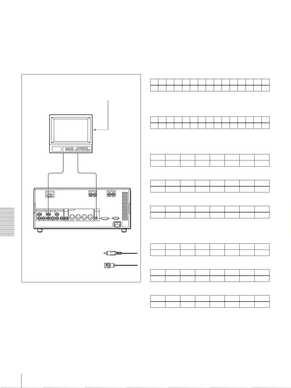
Connection of a video monitor
Set up the following connections to enable monitoring of
video and audio signals on a video monitor. In addition to
the video and audio signals, you can have time data, the
operation mode of the unit, alarm messages, and other
information displayed as text on the monitor screen by
setting the CHARA. DISPLAY menu item (see page 40)
to ON (factory default setting).
75 Ω termination switch: ON (or
attach a 75 Ω terminator.)
Input switches: Set according to the
type of input signals.
Video monitor
Composite
video input
Audio input
Settings on an editing control unit
When connecting an editing control unit, make the settings
as follows, according to the model.
PVE-500
No settings are required.
BVE-600/900/910/2000 (NTSC model) or FXE-100/
120
Set the VCR constants as follows.
123456789101112131415
80 16 00 96 05 05 03 80 0A 08 FE 00 80 5A FF
BVE-600/900/910/2000 (PAL model) or FXE-100P/
120P
Set the VCR constants as follows.
123456789101112131415
81 16 00 7D 05 05 02 80 0A 07 FE 00 80 4C FF
RM-450/RM-450CE
Set the DIP switches as follows.
• Left switches
76543210
OFF −−OFF −−−−
VIDEO
OUT
2(SUPER)
21
AUDIO
MONITOR OUT
• Right switches (RM-450)
)
76543210
OFF − OFF ON OFF OFF ON ON
• Right switches (RM-450CE)
76543210
ON − OFF ON OFF OFF ON ON
BVE-800
Chapter 5 Connections and Settings
A Cable with RCA phono plugs
B 75 Ω coaxial cable
DSR-1600A/1600AP
(not supplied)
(not supplied)
Set the DIP switches as follows.
• SW2
12345678
ON OFF ON ON − ON ON −
• SW3 (NTSC model)
12345678
ON ON ON OFF − ON OFF OFF
• SW3 (PAL model)
12345678
OFF OFF OFF ON − ON OFF OFF
Connections for an A/B Roll Editing System
56
Page 57
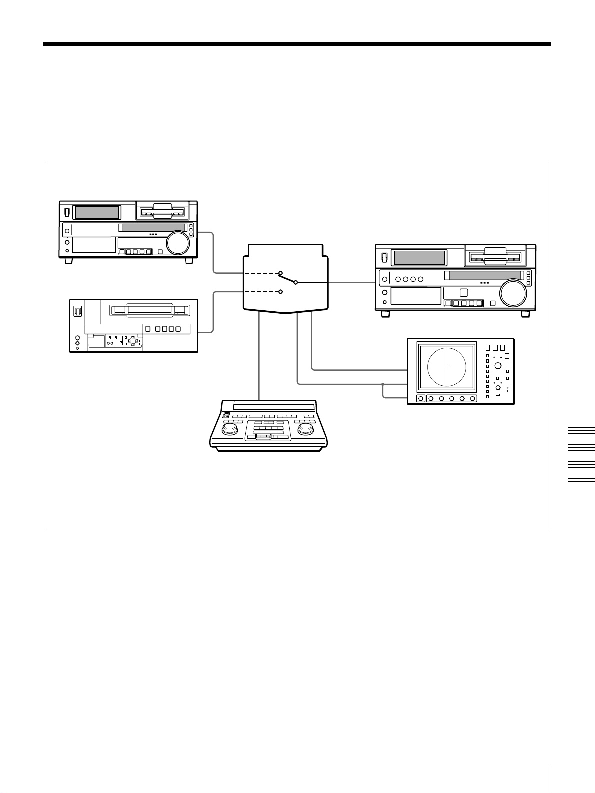
Adjusting the Sync and Subcarrier Phases
When using two or more players, as in an A/B roll editing
system, it is necessary to synchronize the sync and
subcarrier (for composite signals) phases of the signals to
be edited. If they are not synchronized, picture instabilities
or color break-up may occur at edit points.
DSR-1600A/1600AP (player 1)
Switcher (DFS-500/500P, etc.)
UVW-1600/1600P, etc. (player 2)
After configuring the editing system, use a vectorscope to
adjust the sync and subcarrier phase of the recorder and
players. Subcarrier phase adjustment is necessary when
using composite signals and Y/C signals.
a)
75 Ω coaxial cable (A)
75 Ω coaxial cable (B)
DSR-1800A/1800AP (recorder)
b)
b)
a) The sync and subcarrier phase of the
output signal from the DFS-500/500P
switcher are automatically adjusted.
b) Ensure that the 75 Ω coaxial cables (A) and
(B) (not supplied) are of the same length.
Vectorscope
Editing control unit
(PVE-500, etc.)
Chapter 5 Connections and Settings
Adjusting the Sync and Subcarrier Phases
57
Page 58

Performing a phase adjustment operation
1 Press the SCH button on the vectorscope.
Note
When component signals are used the subcarrier phase
indicator does not appear.
The vectorscope switches to SCH mode.
2 Press the B channel button on the vectorscope.
This displays the black burst signal from the switcher.
3 Press the EXT button on the vectorscope.
This switches the vectorscope to external
synchronization mode.
4 Adjust the phase synchronization control on the
vectorscope so that the sync and subcarrier phases are
close to the reference line.
Sync phase
Subcarrier phase
Align the sync and subcarrier phases of the black
burst signal to the reference line.
Reference line
8 Output the player 2 signal and repeat steps 6 and 7 to
adjust the sync and subcarrier phases of the output
from player 2.
5 Output the player 1 signal.
6 Press the A channel button on the vectorscope.
This displays the sync and subcarrier phases
Chapter 5 Connections and Settings
(composite signals only) of the signal from player 1.
7 On player 1, adjust the SYNC PHASE and SC PHASE
controls on the menu control panel, using a Phillips
screwdriver, so that the output from player 1 on
channel A is in correct phase alignment with the black
burst signal on channel B.
This indicator
moves as you
turn the SYNC
PHASE control.
Adjust the sync and subcarrier phases of the output
signal from player 1.
This indicator
moves as you
turn the SC
PHASE control.
Adjusting the Sync and Subcarrier Phases
58
Page 59

Maintenance and
Troubleshooting
Maintenance
Condensation
If you move the unit suddenly from a cold to a warm
location, or if you use it in a very humid place, moisture
from the air may condense on the head drum. This is called
condensation, and if a tape is run in this state, the tape may
stick to the drum and can be easily damaged. To lessen the
risk of this occurring, this unit is equipped with a
condensation detection system.
If condensation occurs while the unit is
operating:
The alarm message “MOISTURE HAS BEEN
DETECTED.” appears on the monitor screen, and the
alarm message “HUMID!” in the time counter display. At
the same time the unit ejects the cassette automatically. If
this happens, leave the unit powered on and wait until the
alarm messages disappear.
If the condensation alarm message appears
immediately after powering on:
Leave the unit powered on and wait until the alarm
message disappears. You cannot load a cassette into the
unit while the alarm message is being displayed.
Once the alarm message disappears, the unit is ready for
use.
Chapter 6
Regular Checks
Digital hours meter
The digital hours meter keeps cumulative counts of the
total operating time, the head drum rotation time, the tape
transport operating time, and the number of threading/
unthreading operations. These counts can be displayed on
the monitor screen and in the time counter display of this
unit. Use them as guidelines for scheduling maintenance.
In general, consult your Sony dealer about necessary
periodic maintenance checks.
Digital hours meter display modes
The digital hours meter has the following four display
modes.
• T1 (OPERATION) mode
The cumulative total hours during which the unit is
powered on is displayed in 10-hour increments.
• T2 (DRUM ROTATION) mode
The cumulative total hours of drum rotation with tape
threaded is displayed in 10-hour increments.
• T3 (TAPE RUNNING) mode
The cumulative total hours of tape transport operation
for fast forward, rewind, playback, and search (except in
still search mode) is displayed in 10-hour increments.
• CT (THREADING) mode
The cumulative number of tape threading/unthreading
operation pairs is displayed in 10-operation pair
increments.
For all modes except T1 (OPERATION), there are two
types of count: a “trip” count, which is resettable, and the
cumulative total from manufacture, which is unresettable.
Maintenance
59
Page 60

Displaying the digital hours meter
Use the following procedure.
1 Press the MENU button on the menu control panel.
Digital hours meter indications on the monitor
screen
All four counts (T1, T2, T3, and CT) are indicated on the
monitor screen.
The menu selection level display appears on the
monitor screen and in the time counter display.
Menu selection level display
SYSTEM MENU
SETUP MENU
HOURS METER
Monitor screen
Setup menu
Time counter display
2 Press the j button to select “HOURS METER.”
SYSTEM MENU
SETUP MENU
HOURS METER
Monitor screen
Hours meter
Time counter display
3 Press the k button.
Resettable trip counts
Unresettable counts
HOURS METER
T1 00000 X10 HOURS
T2 0000/00000 X10 HOURS
T3 0000/00000 X10 HOURS
CT 0000/00000 X10 COUNT
T1:OPERATION
T2:DRUM ROTATION
T3:TAPE RUNNING
CT:THREADING
The four-digit value to the left of the slash (/) is the
resettable trip count, and the right value is the cumulative
total from manufacture.
Digital hours meter indications in the time
counter display
One of the four indications appears in the time counter
display at a time. Use the J and j buttons on the menu
control panel to change the item displayed.
Initially, only the trip value appears. Hold down the k
button to display also the cumulative total from
manufacture, which will appear to the right of the trip
value and the slash (/).
The following illustrates the digital hours meter
indications in the time counter display in all four display
modes. The right-hand indication for each display mode is
the indication you can view while holding down the k
button on the menu control panel.
Chapter 6 Maintenance and Troubleshooting
60
The cumulative counts by the digital hours meter are
indicated on the monitor screen and in the time counter
display.
Maintenance
T1 (OPERATION) mode:
Oper. 00000
T2 (DRUM ROTATION) mode:
Drum 0000
T3 (TAPE RUNNING) mode:
Tape 0000
CT (THREADING) mode:
Thread 0000
0000/00000
0000/00000
0000/00000
Page 61

To end the digital hours meter display
Press the MENU button on the menu control panel.
To reset the trip values
About this operation, consult your Sony dealer.
Head Cleaning
Always use the DVM12CL (mini size) or DV12CL
(standard size) Cleaning Cassette to clean the video and
audio heads. You can run the cleaning cassette for 10
seconds per cleaning operation. Follow the instructions for
the cleaning cassette, as inappropriate use of the cleaning
cassette can damage the heads.
To clean the heads
Insert the cleaning cassette. This automatically starts
cleaning. You cannot operate any tape transport control
buttons other than the EJECT button during the cleaning
operation.
After about 10 seconds, the cleaning cassette will be
automatically ejected.
Maintenance
Chapter 6 Maintenance and Troubleshooting
61
Page 62
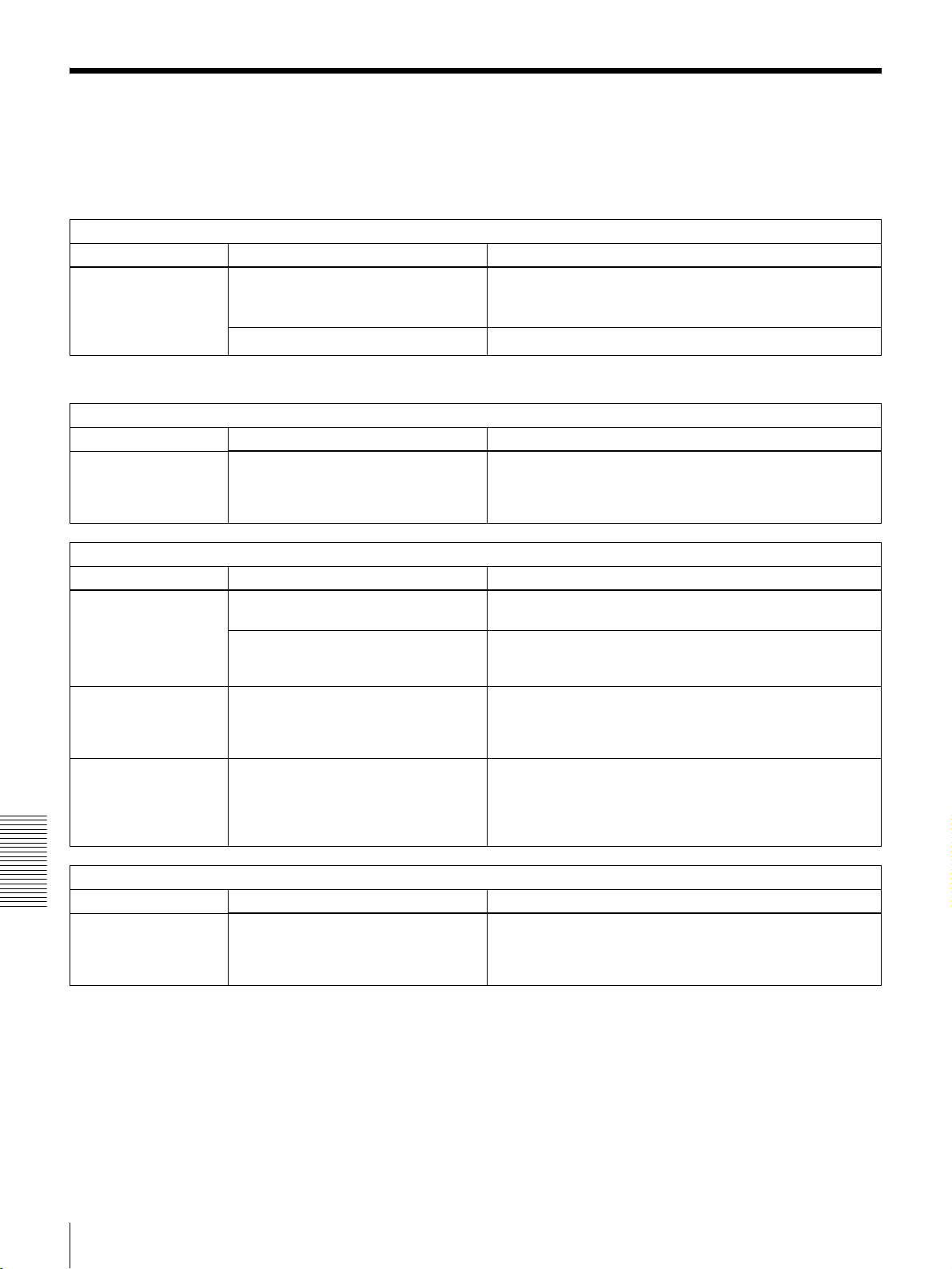
Troubleshooting
If an alarm message appears on the monitor screen, or if
the unit appears to be malfunctioning, please check the
following before contacting your Sony dealer.
Tape problem
Symptom Cause Remedy
The unit’s tape
transport control
buttons (PLAY, F FWD,
REW, etc.) do not
work.
a) In these states, an alarm message appears on the monitor screen and in the
time counter display.
Time data problem
Symptom Cause Remedy
The tape is running,
but the time data is not
shown in the time
counter display.
Monitor problems
Symptom Cause Remedy
Data is not
superimposed on the
monitor screen.
The image on the
monitor screen is too
bright.
The image on the
monitor screen is too
dark.
The REMOTE button is lit and the
LOCAL ENABLE menu item is set to
STOP & EJECT or ALL DISABLE.
No cassette is loaded.
The U-BIT time data type indicator is lit. Press the COUNTER SEL button to make the COUNTER or
The CHARA. DISPLAY menu item is
set to OFF.
The monitor is not connected to the
VIDEO OUT 2 (SUPER) connector of
this unit.
The 75 Ω termination switch for video
input on the monitor is in the OFF
position, or a 75 Ω terminator is not
fitted to its video input connector.
In a video signal loop-through
connection of video monitors, 75 Ω
termination switches for video input on
monitors other than the loop-end
monitor are in the ON position.
a)
Press the REMOTE button to turn it off, or change the setting
of the LOCAL ENABLE menu item (see page 38) to ALL
a)
ENABLE.
Insert a cassette (see page 21).
TC time data type indicator light up.
Set the CHARA. DISPLAY menu item (see page 40) to ON.
Connect the monitor to the VIDEO OUT 2 (SUPER)
connector. (You must make this connection to display any
type of text on the monitor.)
Set the 75 Ω termination switch to ON or connect a
terminator.
Set the 75 Ω termination switches to OFF on all monitors
other than the loop-end monitor.
i.LINK interface problems
Symptom Cause Remedy
Chapter 6 Maintenance and Troubleshooting
This unit cannot be
recognized or
controlled by computer
via i.LINK interface.
Troubleshooting
62
Performance of i.LINK interface is not
guaranteed with all IEEE 1394 devices.
It is only guaranteed as a tape dubbing
facility between VTRs.
• Check the computer for connections and setup.
• Contact your computer hardware/software manufacturer to
check system requirements and product compatibility.
Page 63
Error Messages
This unit is provided with a self-diagnostic function that
detects internal abnormalities. When it detects an
abnormality, it outputs an error message to the monitor
screen and indicates an error code in the time counter
display.
ERROR
AN ERROR HAS BEEN
DETECTED. INFORM SERVICE
OF FOLLOWING CODE:
02-603
PRESS EJECT KEY
TO EJECT TAPE.
Monitor screen
If an error message appears, follow the direction indicated
on the monitor screen.
Alarm Messages
Note
To display error messages on the monitor screen, connect
the monitor to the VIDEO OUT 2 (SUPER) connector, and
set the CHARA. DISPLAY menu item (see page 40) to
ON (factory default setting).
Error message
Error code
Direction
Error code
Error02-603
Time counter display
When operating this unit, the unit may sometimes output
alarm messages such as the one shown below to the
monitor screen and the time counter display.
ALARM
REMOTE MODE IS SELECTED
PRESS REMOTE BUTTON
TURNING IT OFF
Monitor screen
If such an alarm message appears, a connection or
operation error may have been made, or condensation on
heads may have occurred. Follow the direction indicated
on the monitor screen.
Cause of
alarm
Direction
REMOTE!
Time counter display
Note
To display alarm messages on the monitor screen, it is
necessary for the monitor to be connected to the VIDEO
OUT 2 (SUPER) connector, and set the following menu
items to ON.
• CHARA. DISPLAY (see page 40)
•ALARM (see page 41)
• REF ALARM (see page 41)
Chapter 6 Maintenance and Troubleshooting
Troubleshooting
63
Page 64

Alarm messages and associated directions
Alarm message on monitor screen
(Cause)
A cleaning tape has been inserted. The tape will automatically be ejected after cleaning is
Abnormal settings selected in setup
menu.
Cassette adaptor not usable. Use a tape without cassette adaptor. Adaptor!
Moisture has been detected. Keep the power on and wait until this alarm message
No cassette in VTR. Load a cassette. No Cass.!
Remote mode is selected. Turn off the REMOTE button. REMOTE!
Tape cannot be replayed. Use a tape recorded in 525/60 format. (For DSR-
Tape end has been detected. Use a new cleaning tape. Tape end!
Tape not usable. Use a DVCAM/DV/DVCPRO (25M) tape. ILL. Tape!
Direction Alarm message in time
counter display
completed.
Correct the setup menu settings. Contact your Sony
dealer if this alarm message appears again after
making corrections.
disappears.
1600A)
Use a tape recorded in 625/50 format. (For DSR1600AP)
Cleaning Tp
ILL. SETUP!
HUMID!
625/50 Tape
(For DSR-1600A)
525/60 Tape
(For DSR-1600AP)
Chapter 6 Maintenance and Troubleshooting
64
Troubleshooting
Page 65

Precautions
Appendixes
Avoid violent impacts
Dropping the unit, or otherwise imparting a violent shock
to it, is likely to cause it to malfunction.
On safety
• Should any liquid or solid object fall into the cabinet,
unplug the unit and have it checked by qualified
personnel before operating it further.
• Unplug the unit from the wall outlet if it is not to be used
for an extended period of time.
• To disconnect the cord, pull it out by the plug. Never pull
the cord itself.
On operation and storage locations
Avoid operation or storage in any of the following places.
• Location subject to extremes of temperature (operating
temperature range 5ºC to 40ºC (41ºF to 104ºF))
• Location subject to direct sunlight for long periods, or
close to heating appliances (Note that the interior of a car
left in summer with the windows closed can exceed 50ºC
(122ºF).)
• Damp or dusty places
• Location subject to severe vibrations
• Location near equipment generating strong
electromagnetic emissions
• Location near transmitting stations generating strong
radio waves
Operate the unit in a horizontal position
This unit is designed to be operated in a horizontal
position. Do not operate it on its side, or tilted through an
excessive angle (exceeding 20º).
Do not obstruct ventilation openings
To prevent the unit from overheating, do not obstruct
ventilation openings, by for example wrapping the unit in
a cloth while it is in operation.
On cleaning
If the casing or panel is dirty, wipe it gently with a soft dry
cloth. In the event of extreme dirt, use a cloth steeped in a
neutral detergent to remove the dirt, then wipe with a dry
cloth. Applying alcohol, thinners, insecticides, or other
volatile solvents may result in deforming the casing or
damaging the finish.
On repacking and shipping
Save the original shipping carton and packing material;
they will come in handy if you ever have to ship your unit.
For maximum protection, repack your unit as it was
originally packed at the factory, and take care not to impart
violent shocks in transit.
Precautions
65
Page 66
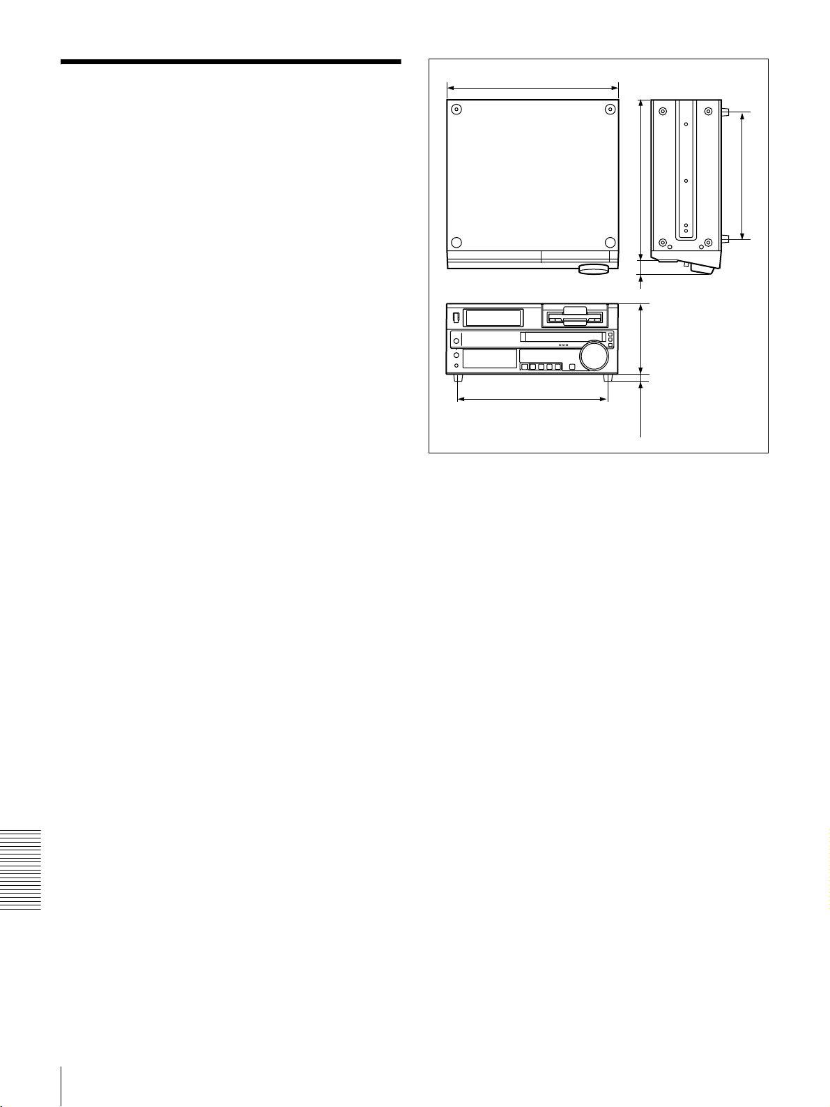
Specifications
General
Signal system DSR-1600A: NTSC
DSR-1600AP: PAL
Power requirements
100 V to 240 V AC, 50/60 Hz
Power consumption (with all options installed)
DSR-1600A:
70 W/120 V
DSR-1600AP for Europe:
70 W/220 V
Peak inrush current
(1)Power ON, current probe method:
40 A (100 V), 40 A (240 V)
(2)Hot switching inrush current,
measured in accordance with
European standard EN55103-1:
40A (230 V)
Operating temperature
5ºC to 40ºC (41ºF to 104ºF)
Storage temperature
−20ºC to +60ºC (−4ºF to +140ºF)
Operating relative humidity
Less than 80%
Storage relative humidity
Less than 90%
Mass 13 kg (28 lb 10 oz)
Dimensions (w/h/d, excluding projections)
427 × 174 × 400 mm
7
(16
/8 × 67/8 × 153/4 inches)
Appendixes
427(16 7/8)
320(12 5/8)
372(14 3/4)
Unit: mm (inches)
400(15 3/4)
34(1 3/8)
174(6 7/8)
18(23/32)
Tape transport control system
Tape speed DSR-1600A: 28.193 mm/s
DSR-1600AP: 28.221 mm/s
Playback time
Using PDV-184ME standard-size
cassette:
Maximum 184 minutes
Using PDVM-40ME mini-size cassette:
Maximum 40 minutes
Fast forward/rewind time
Using PDV-184ME standard-size
cassette:
Less than 3 minutes
Using PDVM-40ME mini-size cassette:
Less than 1 minute
Search speed When controlling via RS-422A interface:
Maximum 60 times normal speed in
both directions
When controlling from DSRM-10
Remote Control Unit:
Jog mode: 0 (still) to 2 times normal
speed in both directions
Shuttle mode: 8 speeds from 0 (still) to
16 times normal speed in both
directions
Video performance
Band width Composite (DSR-1600A):
30 Hz to 4.2 MHz ±1.0 dB (Y)
Composite (DSR-1600AP):
25 Hz to 4.8 MHz ±1.0 dB (Y)
66
Specifications
Page 67

S-video (DSR-1600A):
30 Hz to 5.0 MHz ±1.0 dB (Y),
5.75 MHz +0/−3.0 dB (Y) (TM)
S-video (DSR-1600AP):
25 Hz to 5.0 MHz ±1.0 dB (Y),
5.5 MHz +1.0/−2.0 dB (Y),
5.75 MHz +0/−3.0 dB (Y) (TM)
Component (DSR-1600A):
30 Hz to 5.0 MHz ±1.0 dB (Y),
5.75 MHz +0/−3.0 dB (Y) (TM),
30 Hz to 1.3 MHz ±1.0 dB (C),
1.5 MHz +0/−5.0 dB (C)
Component (DSR-1600AP):
25 Hz to 5.0 MHz ±1.0 dB (Y),
5.5 MHz +1.0/−2.0 dB (Y),
5.75 MHz +1.0/−3.0 dB (Y) (TM),
25 Hz to 1.5 MHz ±1.0 dB (C),
2.0 MHz +1.0/−2.0 dB (C)
S/N Composite output (Y):
53 dB or more
S-video output (Y): 55 dB or more
Component output (Y): 55 dB or more
Y/C delay 30 ns or less
K-factor 2.0% or less (K2T, KPB)
Processor adjustment range
Video level ±3 dB/−∞ to 3 dB selectable
Chrome level ±3 dB/−∞ to 3 dB selectable
Setup/Black level
±30 IRE (±210 mV)
Chroma phase ±30°
Y/C delay ±100 ns
System phase Sync: ±1 μs
*
SC: ±180°
*+2 μs to –3 μs when using a TBC remote control unit
Audio performance
Frequency response
Two-channel (48 kHz) mode:
20 Hz to 20 kHz +0.5 dB/−1.0 dB
Four-channel (32 kHz) mode:
20 Hz to 14.5 kHz +0.5 dB/−1.0 dB
Dynamic range More than 90 dB
Distortion (THD + N)
Less than 0.05% (48 kHz)
Input connectors
Analog video inputs
REF. VIDEO IN
BNC type (×2, loop-through)
Black burst
0.286 Vp-p (DSR-1600A) or 0.3 Vp-p
(DSR-1600AP), 75 Ω, negative sync
Composite sync
Output connectors
Digital signal outputs
SDI OUT (with optional DSBK-1601 SDI/AES/EBU
Output Board installed)
BNC type (×2, active-through), Serial
Digital Interface format (270 Mbps),
SMPTE 259M/ITU-R BT.656
DV IN/OUT 6-pin IEEE 1394 connector
Analog video outputs
REF. VIDEO OUT
BNC type ×1
Black burst
0.286 Vp-p (DSR-1600A) or 0.3 Vp-p
(DSR-1600AP), 75 Ω, negative sync
Composite sync
VIDEO OUT 1, 2 (SUPER)
BNC type (×2), composite, 1.0 Vp-p,
75 Ω, sync negative
COMPONENT VIDEO OUT
BNC type (×3), Y/R−Y/B−Y
Y: 1.0 Vp-p, 75 Ω, sync negative
R−Y: 0.7 Vp-p, 75 Ω (75% color bars
for DSR-1600A or 100% color bars for
DSR-1600AP)
B−Y: 0.7 Vp-p 75 Ω (75% color bars
for DSR-1600A or 100% color bars for
DSR-1600AP)
S VIDEO OUT DIN 4-pin
Y: 1.0 Vp-p, 75 Ω, sync negative
C: 0.286 Vp-p (DSR-1600A) or
0.3 Vp-p (DSR-1600AP), 75 Ω (burst
level)
Analog audio outputs
AUDIO OUT XLR 3-pin, male (× 4), +4/0/−3
600 Ω loading, low impedance,
balanced
AUDIO MONITOR OUT
Phono jack, 47 kΩ, unbalanced
−∞ to −11 dBu ±1 dBu, −20 dBFS
(DSR-1600A)
−∞ to −9 dBu ±1 dBu, −18 dBFS
(DSR-1600AP)
*
/−6 dBu,
Appendixes
* Selectable on DSR-1600AP only
Specifications
67
Page 68
Digital audio outputs
DIGITAL AUDIO (AES/EBU) OUT (with optional
DSBK-1601 SDI/AES/EBU Output Board installed)
BNC type (×2), complying with AES-
3id-1995
Output for headphones
HEADPHONES
Stereo phone jack, 8 Ω, unbalanced
−∞ to −13 dBu, −20 dBFS
(DSR-1600A)
−∞ to −11 dBu, −18 dBFS
(DSR-1600AP)
Time code output
TIME CODE OUT
BNC type, SMPTE time code (DSR-
1600A), EBU time code (DSR1600AP), 2.2 Vp-p ±3 dB, 600 Ω,
unbalanced
Remote control connectors
REMOTE D-sub 9-pin, female, for connection of
editing control unit, RS-422A standard
CONTROL S Stereo minijack, for connection of
SIRCS-compatible remote control unit
(DSRM-10)
VIDEO CONTROL
D-sub 15-pin, male, for connection of
TBC remote control unit
DV IN/OUT
6-pin IEEE 1394 connector
Note
Always verify that the unit is operating properly before
use.
SONY WILL NOT BE LIABLE FOR DAMAGES OF
ANY KIND INCLUDING, BUT NOT LIMITED TO,
COMPENSATION OR REIMBURSEMENT ON
ACCOUNT OF THE LOSS OF PRESENT OR
PROSPECTIVE PROFITS DUE TO FAILURE OF
THIS UNIT, EITHER DURING THE WARRANTY
PERIOD OR AFTER EXPIRATION OF THE
WARRANTY, OR FOR ANY OTHER REASON
WHATSOEVER.
Supplied accessories
AC power cord (1)
Operating Instructions
English version (1)
CD-ROM manual (1)
Optional accessories
DSBK-1601 SDI/AES/EBU Output Board
RCC-5G 9-pin remote control cable (length: 5 m (16 ft))
RMM-131/1 Rack Mount Kit
Digital video cassette
Standard size: PDV-34*/64*/94*/124*/
Mini size: PDVM-12*/22*/32*/40*
a) The * in each model name is actually “ME”
Appendixes
Cleaning cassette
DV12CL (standard size), DVM12CL
Design and specifications are subject to change without
notice.
a)
184*
(indicating that a cassette memory is contained), or
“N” (indicating that no cassette memory is
contained).
(mini size)
a)
68
Specifications
Page 69

Glossary
A/B roll editing
An editing method that uses two or
more playback VCRs to create
special effects such as dissolve and
wipe, and uses one record VCR to
record the results of the editing.
Using an editing control unit allows
efficient control of the VCRs and
very precise editing.
AES/EBU format
A unified format for digital audio
signals. It allows a single connector
to carry the signals for two channels.
B−Y signal
A chrominance signal determined by
subtracting the Y (luminance) signal
from the B (blue) signal. One of the
component signals.
C (chrominance) signal
Color signal containing color
information such as hue and
saturation.
Capstan
A drive mechanism that moves the
tape at a specified speed. Its rotation
normally synchronizes with a
reference sync signal.
Component signals (YRB)
A video signal consisting of a
luminance signal (Y) and two
chrominance signals (R−Y, B−Y).
Composite signal
A composite video signal containing
video, burst and sync signals.
Condensation
Condensation of moisture on the tape
transport mechanisms of VCRs
including the head drum. If moisture
condenses on the head drum, the tape
adheres to the drum and causes
malfunction.
Drop frame mode
Time code runs at 30 frames/sec. The
NTSC system, however, runs at
about 29.97 frames/sec. Drop frame
mode adjusts this difference. The
time code and video are synchronized
by dropping the first two frames of
the time code every minute, except at
the ten-minute marks.
Head drum
A metal cylinder to which a video
head is attached. This drum is rotated
at high speeds in synchronization
with the sync signal during recording
and playback.
Linear editing
Editing while playing back video and
audio signals recorded on video tape.
See also “Non-linear editing.”
Loading
When being loaded, the tape is pulled
out of the cassette case and threaded
along the specified tape path and
wrapped round the drum to be ready
for recording or playback. Generally,
this is done automatically when you
place the cassette at the cassette
entrance of the VCR. Also called
threading.
Loop-through connection
A connection which allows a signal
input to an input connector to pass
through the unit and exit from an
output connector as input to external
equipment. Also called bridging
connection.
Luminance signal
The signal that determines the
brightness of the picture. Also called
Y signal. One of the component
signals.
Non-drop frame mode
The number of frames of the time
code and video run is not adjusted.
When you use the time code in nondrop frame mode, the real playback
time will be about 86 seconds shorter
per day than the time code. If you edit
frame by frame or if you determine
the length of a shot by counting the
time code, use drop frame mode.
Non-linear editing
Editing while playing back video and
audio signals recorded on hard disks.
Video scenes stored on disk can be
cued up quickly, for increased editing
efficiency. See also “Linear
editing.”
PCM audio
This is an audio signal represented by
pulse code modulation. The analog
audio signal is first broken down into
a sequence of pulses, and these are
then represented digitally.
Preroll
Running of a video tape to a prior to
an edit-start point to enable the tape
to reach a steady speed and to be
synchronized with other video tapes.
R−Y signal
A chrominance signal determined by
subtracting the Y (luminance) signal
from the R (red) signal. One of the
component signals.
Reference video signal
A video signal consisting of a sync
signal or sync and burst signals, used
as a reference.
Setup (for DSR-1600A)
The difference between the reference
black level and the blanking level of
a composite signal.
SMPTE
Abbreviation of Society of Motion
Picture and Television Engineers, a
professional association established
in the USA.
Appendixes
Glossary
69
Page 70

S/N
Abbreviation of Signal-to-Noise
(ratio). The higher the S/N value, the
less noise and higher the picture
quality.
Search mode
A VCR operating mode used when
searching for specific scenes, by
viewing the video output or time code
values while playing back the tape at
various speeds in forward or reverse
direction.
Servo lock
Synchronizing the drum rotation
phase and tape transport phase with a
reference signal during playback and
recording so that the video heads scan
the tape in the same pattern during
playback and recording.
Sync signal
A reference signal consisting of
vertical and horizontal sync signals
used for synchronizing the scanning
patterns of the video camera and the
monitor.
TBC
Abbreviation of Time Base
Corrector. Electronic circuits to
electrically stabilize the playback
signals by removing color variation
and roll in the playback picture
caused by irregularity in drum
rotation and tape movement. Time
base correction reduces deterioration
of picture quality when transmitting
or copying playback signals.
Threading
See “Loading.”
Standby Off mode
One of two conditions in the stop
mode. The drum does not rotate and
tape is slackened. There is no damage
to the video heads and the tape, but
the VCR is not ready for immediate
recording or playback.
Standby On mode
One of two conditions in the stop
mode. The drum is rotating and the
tape is wrapped round the drum. The
VCR is ready for recording or
playback, so a still picture can be
obtained.
Subcarrier
A sine wave imposed on the
luminance portion of a video signal
and modulated to carry color
information. Its amplitude represents
color saturation and its phase
represents hue.
Superimpose
To put a set of characters onto a
picture so that both can be seen at the
same time.
Time code
Signals recorded on the tape to
supply information on tape position
such as the hour, minute, second and
frame, to assist in setting edit points
or searching for particular scenes.
Unloading
When the EJECT button is pressed,
the VCR automatically winds the
tape back into the cassette case. Also
called “Unthreading.”
User bits
Sections of time code information
consisting of a total of 32 bits that can
be used for recording information
such as date, tape ID number,
program ID number, etc.
S-video
A signal format in which Y
(luminance) and C (chrominance)
Appendixes
signals are separated to reduce
interference between them so that
noiseless images are reproduced.
Glossary
70
Page 71

Index
Numerics
9PIN button 14
A
A/B roll editing system 52
AC IN connector 15
AES 7, 17
Alarm messages 63
Analog
audio signal output section 17
video signal output section 16
Arrow buttons 11
Aspect ratio 8
AUDIO (AES/EBU) OUT connectors
17
Audio level meters 9
AUDIO MONITOR OUT connector
18
Audio monitor system connections 53
AUDIO OUT CH-1 to CH-4
connectors 18
Audio performance 67
B
Basic items 35
changing settings 45
C
Cassette compartment 9
Cassette memory 20
indicator 13
Cassettes 19
ejecting 21
inserting 21
CHANNEL CONDITION indicators
13
ClipLink
indicator 13
CNT 30, 32
COMPONENT VIDEO OUT Y/R-Y/
B-Y connectors 16
Condensation 59
Connections
A/B roll editing system 52
audio monitor system 53
control signal 54
cut editing system 51
digital non-linear editing system
49
reference video signal 53
video monitor 56
video/audio signals 55
CONTROL S connector 10
Control signal connections 54
COUNTER 13, 32
COUNTER SEL button 11
Cut editing system 51
Cyclical playback 24
D
Digital
jog sound function 7
non-linear editing system 49
signal output section 17
slow mode 33
Digital hours meter 59
display modes 59
Display section 12
Drop frame indication 31
DSBK-1601 SDI/AES/EBU Output
Board 8, 17
DSR-1600A/1600PA operation modes
31
DV format 6, 12
DVCAM
cassettes 20
format 6, 12
DVCPRO (25M) format 6, 12
E
EBU 7, 13, 17, 30
Editing control unit settings 56
Editing points 33
EJECT button 11
Enhanced items 35
changing settings 47
displaying 47
Error messages 63
External device connectors 18
F
F FWD button 11
Factory defaults (menu) 48
Front panel 9
H
Head cleaning 61
HEADPHONES connector 9
I
i.DV IN/OUT connector 17
i.LINK button 14
Interfaces 7
Internal time code reader 7
J
Jog
audio 33
mode 14, 33
JOG indicator 13
L
LP mode 12
LTC 30
M
Maintenance 59
Menu 35
AUDIO CONTROL 43
basic items 35
changing settings 45
contents 38
digital hours meter 35
DISPLAY CONTROL 40
enhanced items 35
indications on monitor screen 47
initialization 48
MENU GRADE 44
OPERATIONAL FUNCTION
38
organization 35
SETUP BANK OPERATION 44
setup menu 38
TAPE PROTECTION 41
TIME CODE 41
VIDEO CONTROL 42
Menu banks 44
MENU button 11
Menu control panel 10
Monitor problems 62
MONITOR SELECT switches 10
O
Operation mode indications 30
Optional accessories 8
P
PB FS display 9
PCM digital audio 6
PHONE LEVEL control knob 9
PLAY button 11
Playback 19
jog mode 14, 33
procedure 22
shuttle mode 14, 34
Playback format indicators 12
POWER switch 9
Power-on playback function 7
Precautions 65
Index
Index
71
Page 72

Processor adjustment range 67
R
Rack mount 8
Rear panel 15
REC/SAVE switch 20
REF. VIDEO IN/OUT connectors 16
Reference video signals 51
Index
connection 53
Regular checks 59
REMOTE
button 14
connector 18
Remote control 7
setting section 14
REPEAT indicator 13
Repeat playback 7, 24
RESET (NO) button 11
REW button 11
RMM-131/1 Rack Mount Kit 8
S
S VIDEO OUT connector 16
SC PHASE control 11
SDI OUT connectors 17
SDI/AES/EBU 7, 8
Search 33
control section 13
dial 13
via external equipment 33
SEARCH button 13
SERVO indicator 13
SET (YES) button 11
Setup menu 38
SHUTTLE indicator 13
Shuttle mode 14, 33, 34
Slow-motion playback 7
SMPTE 7, 13, 30
Specifications 66
Still mode 33
STOP button 12
Subcarrier phase adjustment 57
Superimposition 8, 16
Sync phase adjustment 57
SYNC PHASE control 11
Time counter display 13, 32
Time data
display 30
problem 62
type 31
type indicators 13
Troubleshooting 62
alarm messages 63
error messages 63
U
U-BIT 13, 32
Usable cassettes 19
User bit data 30, 32
V
Video
performance 66
process control 7
VIDEO CONTROL connector 18
Video monitor connection 56
VIDEO OUT 1 and 2 (SUPER)
connectors 16
Video/audio signal connections 55
VITC 30
field indication 31
indicator 13
W
Wide-screen aspect ratio 8
T
Tape end alarm indicator 13
Tape problem 62
Tape transport control
section 11
system 66
TC 13, 32
Text information display 30
Time code 32
TIME CODE OUT connector 16
Index
72
Page 73

Sony Corporation
http://www.sony.net/
 Loading...