

SONY DSLR-A100 Service Manual
DSLR-A100
SERVICE MANUAL
Ver 1.2 2006.07
Revision History
Revision History
How to use
How to use
Acrobat Reader
Acrobat Reader
Revised-1
Link
Link
SPECIFICATIONS
BLOCK DIAGRAMS
LEVEL 2
US Model
Canadian Model
AEP Model
UK Model
E Model
Australian Model
Hong Kong Model
Chinese Model
Korea Model
Japanese Model
Tourist Model
PRINTED WIRING BOARDS
SERVICE NOTE
DISASSEMBLY
The components identified by
mark 0 or dotted line with
mark 0 are critical for safety.
Replace only with part number specified.
FRAME SCHEMATIC DIAGRAM
SCHEMATIC DIAGRAMS
Les composants identifiés par une
marque 0 sont critiques pour la
sécurité.
Ne les remplacer que par une pièce
portant le numéro spécifié.
DIGITAL SINGLE LENS REFLEX CAMERA
REPAIR PARTS LIST
DSLR-A100_L2
Sony EMCS Co.
2006G0500-1
© 2006.7
Published by Kohda TEC9-852-130-32

SPECIFICATIONS
Camera
[System]
Camera Type Digital Single Lens Reflex
Lens All of Sony Lens
[CCD]
Total pixel number of camera
Effective pixel number of camera
Image sensor 23.6 × 15.8mm (APS-C format)
[Super SteadyShot]
System CCD-Shift mechanism
Super SteadyShot Compensation capability
[Anti-Dust]
System Charge protection coating on
[Viewfinder]
Type Fixed eye-level system with
Focusing Screen Spherical Acute Matte
Field of View 0.95
Magnification 0.83 × with 50 mm lens at
Eye Relief Approximately 20mm from the
Dioptor Adjustment
[Auto Focus System]
System TTL phase-detection system,
Sensitivity Range
Camera with built-in flash and
interchangeable lenses
Approx. 10 800 000 pixels
Approx. 10 200 000 pixels
Interlace scan Primary Color
Approximately 2 EV to 3.5 EV
decrease in shutter speed
(varies according to shooting
conditions and lens used)
Low-Pass Filter and CCD-Shift
mechanism
roof mirror type pentaprism
infinity, –1 m
eyepiece, 16mm from the
eyepiece frame at –1 diopter
(–1m
–2.5 to +1.0 m
CCD line sensors (9 points, 8
lines with center cross-hair
sensor)
0 EV to 18 EV (at ISO 100
equivalent)
–1
–1
)
–1
[Exposure]
Metering Cell 40-segment honeycomb-pattern
Metering Range +1 EV to +20 EV (+4 EV to
SPC
+20 EV with Spot metering),
(at ISO 100 with F1.4 lens)
[Shutter]
Type Electronically-controlled,
Speed range 1/4000 second to 30 seconds,
Flash Sync Speed
vertical-traverse, focal-plane
type
bulb
1/160 second (with Super
SteadyShot off),
1/125 second (with Super
SteadyShot on)
[Built-In-Flash]
Flash G.No. GN 12 (in meters at ISO 100)
Recycling Time Approx. 3 seconds
[Recording media]
CompactFlash card(TypeI,II),
Microdrive, “Memory Stick
Duo” (with Memory Stick Duo
Adaptor for CF Slot)
[LCD monitor]
LCD panel 6.2 cm (2.5type) TFT drive
Total number of dots
230 000 (960×240) dots
[Power, general]
Used battery pack
Rechargeable battery pack
NP-FM55H
[Others]
PictBridge Compatible
Exif Print Compatible
PRINT Image Matching III
Dimensions 133.1 × 94.7 × 71.3 mm
Mass Approx.545 g (1 lb 3.2 oz)
Compatible
(5 1/4 × 33/4 × 27/8 inches)
(W/H/D, excluding protrusions)
(without batteries, recording
medium and body accessories)
Operating temperature
Exif Exif Ver. 2.21
USB communication
0 to +40°C (+32 to +104°F)
(When using the Microdrive:
+5 to +40°C (41 to +104°F))
Hi-Speed USB (USB 2.0
compliant)
BC-VM10 Battery charger
Input rating 100 V to 240 V AC, 50/60 Hz
Output rating 8.4 V DC, 750 mA
Operating temperature range
Storage temperature range
Maximum dimensions
Mass Approx. 90 g (3.2 oz)
0 to +40°C (32 to +104°F)
-20 to +60°C (-4 to +140°F)
Approx. 70 × 25 × 95 mm
(2 7/8 × 1× 3 3/4 inches) (W/H/
D)
Rechargeable battery pack NP-FM55H
Used battery Lithium-ion battery
Maximum voltage
Nominal voltage DC 7.2 V
Capacity 11.5 Wh (1 600 mAh)
Maximum dimensions
Mass Approx. 78 g (2.8 oz)
Design and specifications are subject to change
without notice.
DC 8.4 V
Approx. 38.2 × 20.5 × 55.6 mm
(1 9/16 × 13/16 × 2 1/4 inches)
(W/H/D)
DSLR-A100_L2
— 2 —

TABLE OF CONTENTS
Section Title Page
1. SERVICE NOTE
1-1. Chemicals ········································································ 1-1
1-2. Exterior Parts ···································································1-1
1-3. Unleaded Solder ······························································ 1-1
1-4. Safety Check-out ····························································· 1-1
1-5. Note for Replacing Fuse on the AM-001 Board·············· 1-2
1-6. Demagnetization Method ················································ 1-2
2. DISASSEMBLY
2-1. Disassembly ····································································· 2-2
3. BLOCK DIAGRAMS
3-1. Overall Block Diagram (1/4) ··········································· 3-1
3-2. Overall Block Diagram (2/4) ··········································· 3-2
3-3. Overall Block Diagram (3/4) ··········································· 3-3
3-4. Overall Block Diagram (4/4) ··········································· 3-4
3-5. Power Block Diagram (1/3)·············································3-5
3-6. Power Block Diagram (2/3)·············································3-6
3-7. Power Block Diagram (3/3)·············································3-7
4. PRINTED WIRING BOARDS AND
SCHEMATIC DIAGRAMS
4-1. Frame Schematic Diagram ·············································· 4-1
4-2. Schematic Diagrams ························································4-3
4-3. Printed Wiring Boards ··················································· 4-23
5. REPAIR PARTS LIST
5-1. Exploded Views ·······························································5-2
DSLR-A100_L2
— 3 —

1. SERVICE NOTE
1-1. CHEMICALS
Some chemicals used for servicing are highly volatile.
Their evaporation caused by improper management affects your health and environment, and wastes resources.
Manage the chemicals carefully as follows.
• Store chemicals sealed in a specific place to prevent from exposure to high temperature or direct sunlight.
•Avoid dividing chemicals into excessive numbers of small containers to reduce natural evaporation.
•Keep containers sealed to avoid natural evaporation when chemicals are not in use.
•Avoid using chemicals as much as possible. When using chemicals, divide only required amount to a small plate from the container and
use up it.
1-2. EXTERIOR PARTS
Be careful to the following points for plastic parts used in this unit.
• Use a piece of cleaning paper or cleaning cloth for cleaning plastic parts. Avoid using chemicals.
Even if you have to use chemicals to clean heavy dirt, don’t use paint thinner, ketone, nor alcohol.
• Insert the specific screws vertically to the part when installing a plastic part.
Be careful not to tighten screws too much.
1-3. UNLEADED SOLDER
This unit uses unleaded solder.
Boards requiring use of unleaded solder are printed with the lead free mark (LF) indicating the solder contains no lead.
(Caution: Some printed circuit boards may not come printed with the lead free mark due to their particular size.)
: LEAD FREE MARK
Be careful to the following points to solder or unsolder.
• Set the soldering iron tip temperature to 350 °C approximately.
If cannot control temperature, solder/unsolder at high temperature for a short time.
Caution: The printed pattern (copper foil) may peel away if the heated tip is applied for too long, so be careful!
Unleaded solder is more viscous (sticky, less prone to flow) than ordinary solder so use caution not to let solder bridges occur
such as on IC pins, etc.
• Be sure to control soldering iron tips used for unleaded solder and those for leaded solder so they are managed separately. Mixing
unleaded solder and leaded solder will cause detachment phenomenon.
1-4. SAFETY CHECK-OUT
After correcting the original service problem, perform the following safety checks before releasing the set to the customer.
1. Check the area of your repair for unsoldered or poorly-soldered connections. Check the entire board surface for solder splashes and
bridges.
2. Check the interboard wiring to ensure that no wires are “pinched” or contact high-wattage resistors.
3. Look for unauthorized replacement parts, particularly transistors, that were installed during a previous repair. Point them out to the
customer and recommend their replacement.
4. Look for parts which, through functioning, show obvious signs of deterioration. Point them out to the customer and recommend their
replacement.
5. Check the B+ voltage to see it is at the values specified.
6. Flexible Circuit Board Repairing
•Keep the temperature of the soldering iron around 270 °C during repairing.
• Do not touch the soldering iron on the same conductor of the circuit board (within 3 times).
• Be careful not to apply force on the conductor when soldering or unsoldering.
COMPONENTS IDENTIFIED BY MARK 0 OR DOTTED LINE WITH
MARK 0 ON THE SCHEMATIC DIAGRAMS AND IN THE PARTS
LIST ARE CRITICAL TO SAFE OPERATION. REPLACE THESE
COMPONENTS WITH SONY PARTS WHOSE PART NUMBERS
APPEAR AS SHOWN IN THIS MANUAL OR IN SUPPLEMENTS
PUBLISHED BY SONY.
DSLR-A100_L2
Danger of explosion if battery is incorrectly replaced.
CAUTION
Replace only with the same or equivalent type.
SAFETY-RELATED COMPONENT WARNING!!
ATTENTION AU COMPOSANT AYANT RAPPORT
À LA SÉCURITÉ!
LES COMPOSANTS IDENTIFÉS PAR UNE MARQUE 0 SUR LES
DIAGRAMMES SCHÉMATIQUES ET LA LISTE DES PIÈCES SONT
CRITIQUES POUR LA SÉCURITÉ DE FONCTIONNEMENT. NE
REMPLACER CES COMPOSANTS QUE PAR DES PIÈSES SONY
DONT LES NUMÉROS SONT DONNÉS DANS CE MANUEL OU
DANS LES SUPPÉMENTS PUBLIÉS PAR SONY.
1-1
1-5. NOTE FOR REPLACING FUSE ON THE AM-001 BOARD
The caution label for fuse replacing on the AM-001 board is put under the DD-268 board. When replacing the fuse, remove the DD-268 board
and refer to this label.
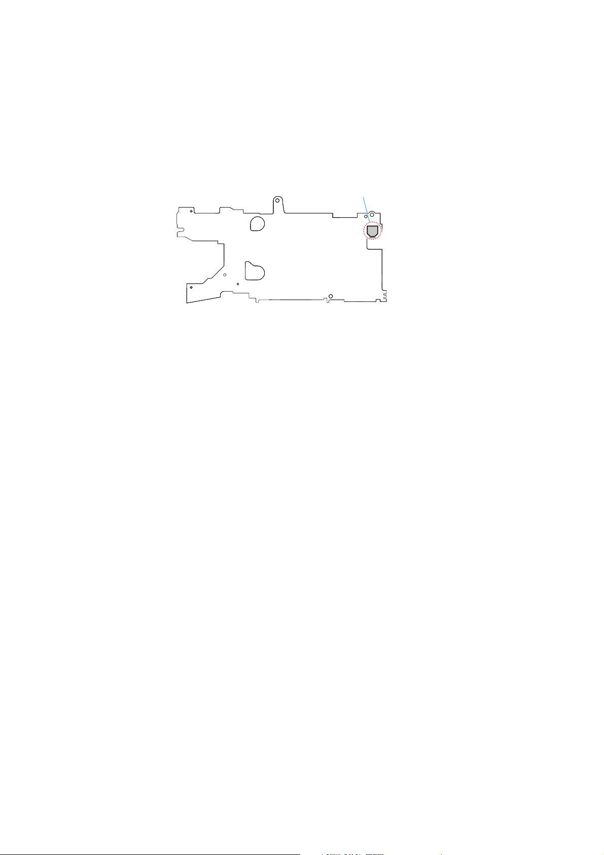
1-6. DEMAGNETIZATION METHOD
It is easy to receive the influence of the outside magnetism because the slant sensor switch (S624) has the magnet in the inside.
Horizontal and vertical cannot be detected when the influence of magnetism is received, and the display of the LCD panel doesn't change.
Therefore, it is necessary to degauss the screw in the vicinity of the switch.
S624
– AM-001 Board: Side B –
Note it because the user magnetizes set occasionally.
Refer to next page for the demagnetization method.
DSLR-A100_L2
1-2
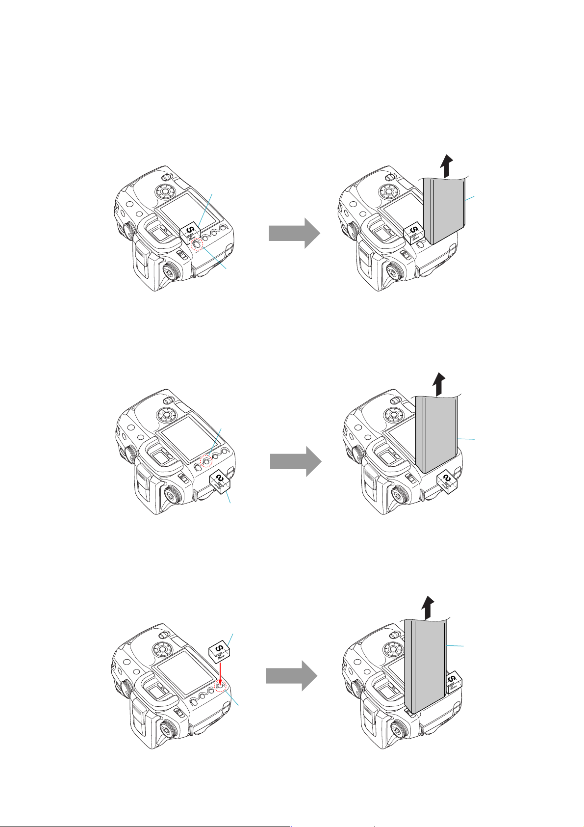
Tools to be prepared:
Push a magnet to the right side of MENU button to
demagnetize.
In the state shown below, operate the demagnetizer for 5 seconds,
and with the demagnetizer operated, detach it in the arrow direction.
At this time, hold the magnet in same position, and remove it after
the demagnetizer was detached.
MENU Button
Magnet
Demagnetizer
Push a magnet to the side of Display button (side surface
of the camera) to demagnetize.
In the state shown below, operate the demagnetizer for 5 seconds,
and with the demagnetizer operated, detach it in the arrow direction.
At this time, hold the magnet in same position, and remove it after
the demagnetizer was detached.
Display Button
Magnet
Demagnetizer
Push a magnet over the Playback button to demagnetize. In the state shown below, operate the demagnetizer for 5 seconds,
and with the demagnetizer operated, detach it in the arrow direction.
At this time, hold the magnet in same position, and remove it after
the demagnetizer was detached.
Magnet
Playback Button
Demagnetizer
Magnet (cover with a tape, etc. for damage prevention)
Demagnetizer
STEP 1:
STEP 2:
STEP 3:
• SLANT SENSOR SWITCH OPERATION INSPECTION
Using the camera already demagnetized, perform the posture switching by five sets, one set comprising “normal posture → Grip up →
Grip down”, to confirm that the LCD display changes over correctly.
DSLR-A100_L2
1-3E
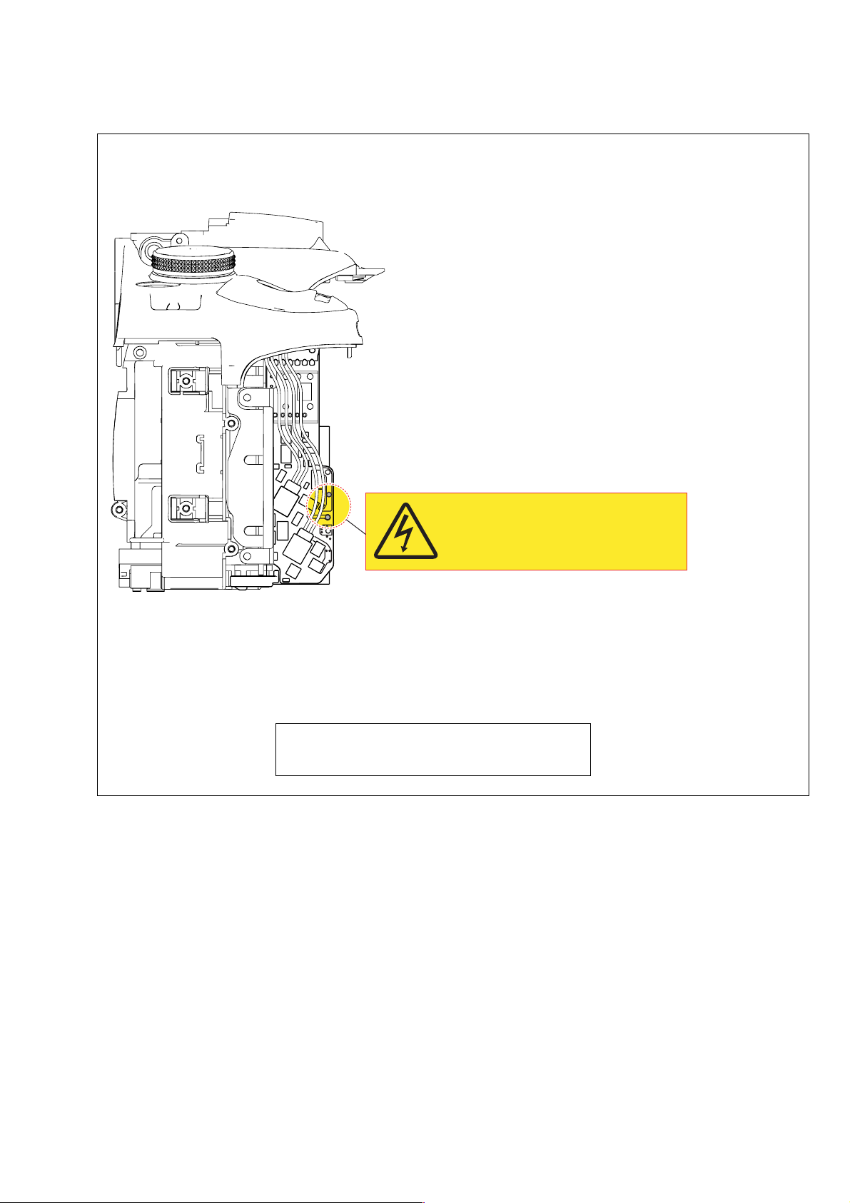
2. DISASSEMBLY
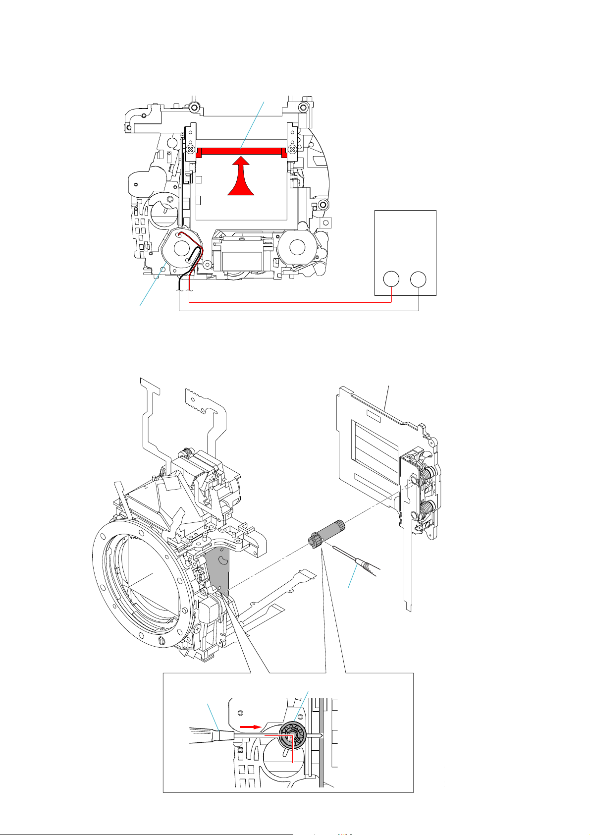
DISCHARGING OF THE MAIN CAPACITOR UNIT
Before disassembly, be sure to discharge the main capacitor unit in the following manner.
Short-circuit the capacitor using the discharger
or a resistor of about 200-300Ω/3W.
After discharge, check the voltage.
SUBSIDIARY MATERIALS
G: Grease B: Bond
G-15 (J-6082-619-A) B-20 (Adhesive (LOCTITE 460)) (Note)
G-85 (J-6082-626-A) B-50 (J-6082-615-A)
G-115 (J-6082-627-A) B-60 (J-6082-616-A)
Note: Use adhesive (LOCTITE 460) or an equivalent article.
Don’t use what becomes white after drying like a quickdrying glue.
DSLR-A100_L2
2-1
HELP
HELP
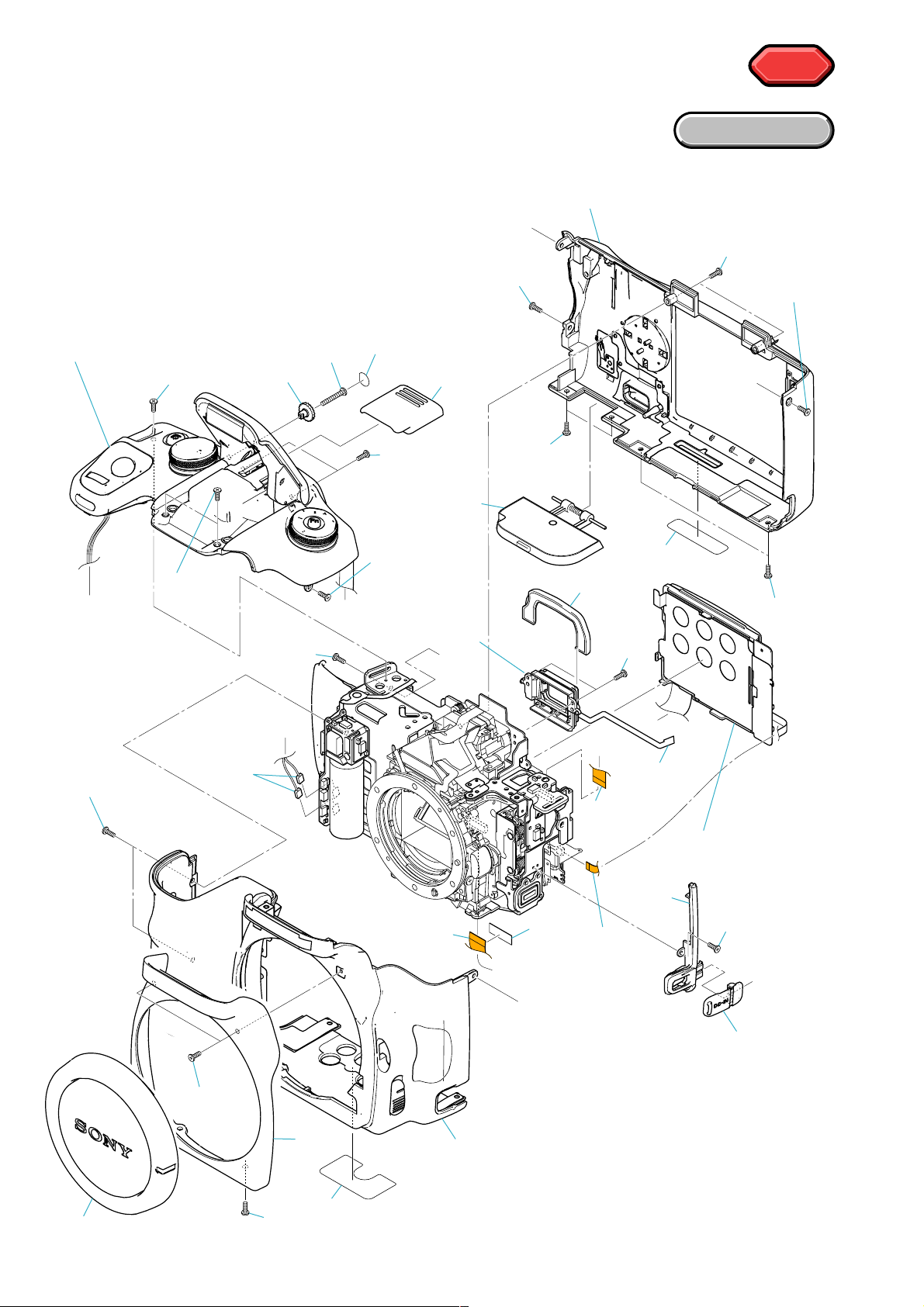
2-1. DISASSEMBLY
2-1-1. OVERALL SECTION
Follow the disassembly in the numerical order given.
1 LCD Holder Unit (1-1 to 1-22)
2 Top Cover Unit (2-1 to 2-11)
3 Eye Piece Frame Unit (3-1 to 3-2)
2 Top Cover Unit
2-10
1-11
1-10
1-9
2-11
2-9
1-3
1-19
(Fig. 1-1)
EXPLODED VIEW
1-18
D
1-17
1-16
1-14
E
1-13
1-4
A
2-1
2-2
2-8
(Fig. 1-3)
1-15
A
B
3 Eye Piece
Frame Unit
1-22
(Fig. 1-2)
D
C
1-21
(Fig. 1-2)
E
1-2
3-2
B
2-7
(Fig. 1-2)
1-20
(Fig. 1-2)
C
3-1
(Fig. 1-4)
1 LCD Holder
(Fig. 1-6, 1-7)
Unit
2-5
2-4
1-12
1-1
DSLR-A100_L2
1-6
1-7
1-8
1-5
(Fig. 1-5)
2-6
2-3
2-2
Red Connector
Wires arrangement
Yellow Connector
Fig. 1-2
FPC Sticking Tape
Fig. 1-3
Battery Cover Unit
Fig. 1-1
Battery Cover Spring
Install it while charging with the hook of the spring.
Slot
DSLR-A100_L2
2-3
Solder 4 points
Don’t tear.
Fig. 1-4
DSLR-A100_L2
S Adjustment Screw
(Yaw adjust)
B: B-50
Fig. 1-5
2-4
S Adjustment Screw
(Pitch adjust)
Claw
CCD AO Adjustment Screw
Claw
This claw does not see
from the outside.
Claw
Screwdriver
Fig. 1-6
CCD AO Adjustment Screw
DSLR-A100_L2
B: B-50
B: B-50
Fig. 1-7
2-5
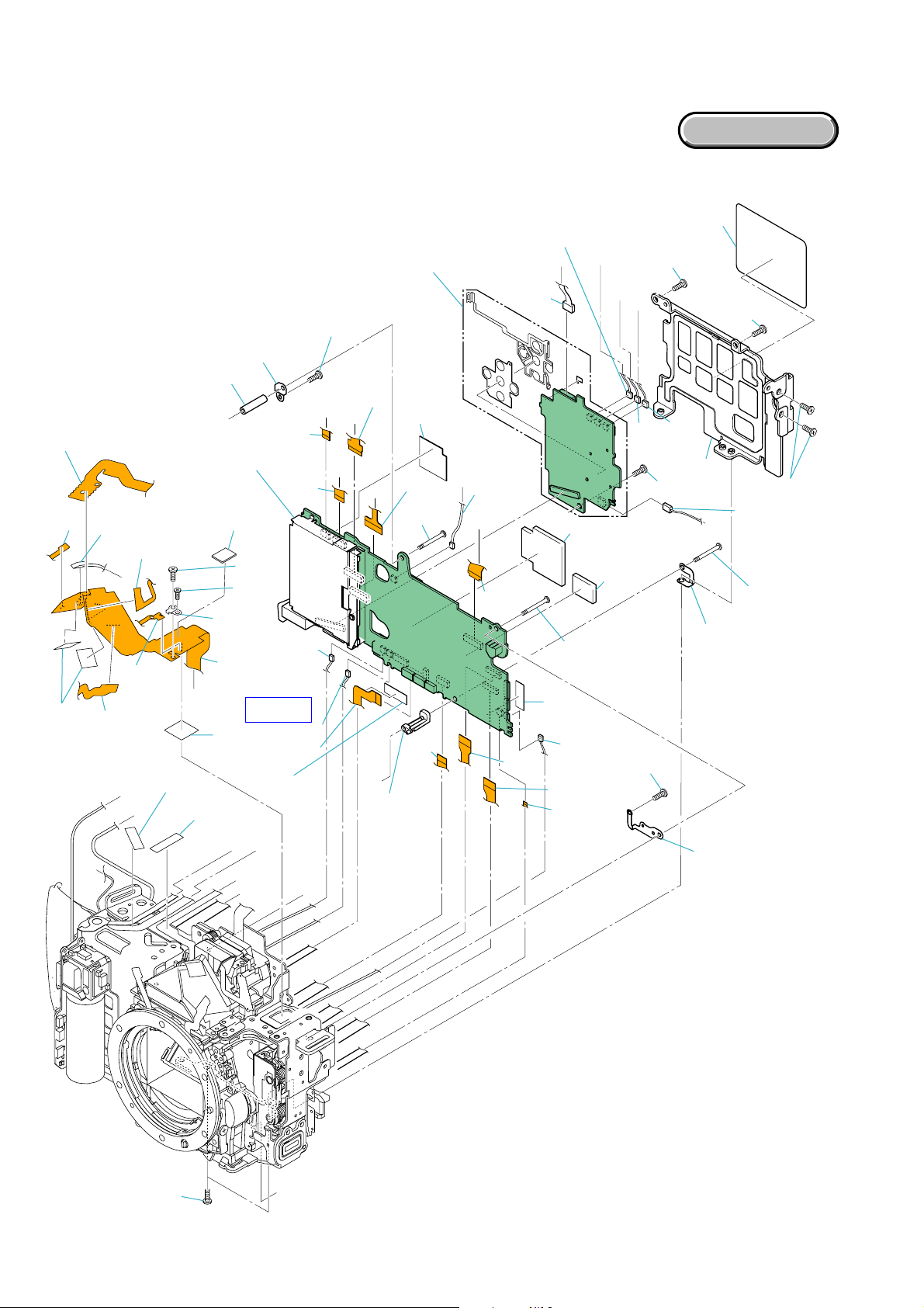
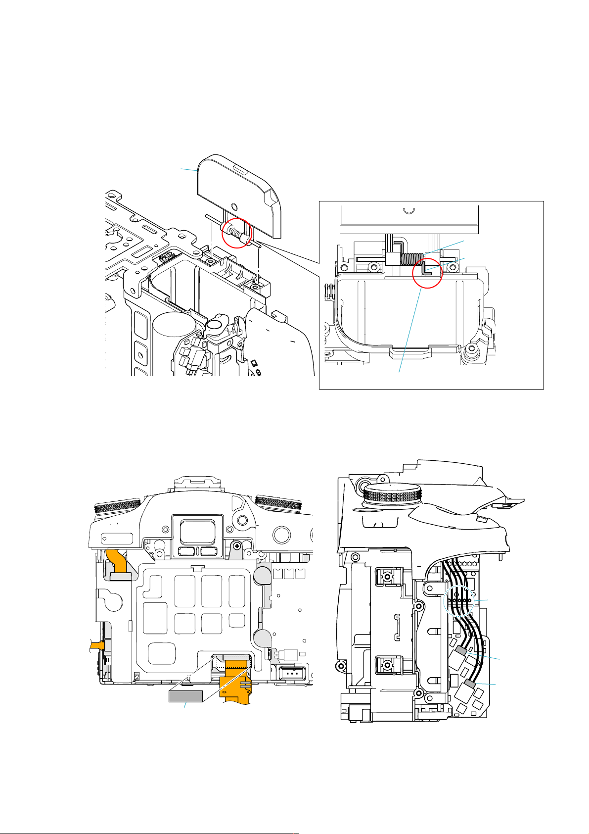
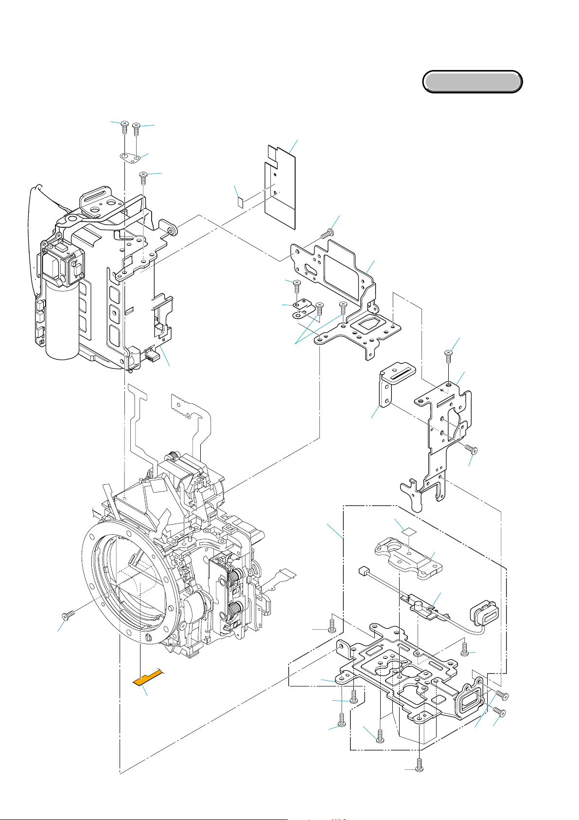
2-1-2. HALF SET BODY-1
Follow the disassembly in the numerical order given.
1 FP-528 Flexible Board (1-1 to 1-22)
2 Power Unit (2-1 to 2-8)
3 AM-001 Board (3-1 to 3-25)
2 Power Unit
2-7 (Fig. 2-2)
I
H
EXPLODED VIEW
1-1
1-6
1-14
1-13
1-22
(Fig. 2-2)
K
1-18
(Fig. 2-4)
1-11
J
1-10
1-12
2-2
(Fig. 2-2)
I
H
3-24
3-25
(Fig. 2-9)
(Fig. 2-9)
L
3-5
3 AM-001 Board
(Fig. 2-8)
1-2 (Fig. 2-2)
1-16
1-15
1-17
(Fig. 2-2)
3-6
3-7
1 FP-528
F
(Fig. 2-1)
HELP
1-21
(Fig. 2-2)
3-1
(Fig. 2-2)
A
D
C
3-8
3-10
3-9
(Fig. 2-8)
B
L
3-23
3-4
(Fig. 2-7)
A
C
B
3-2
(Fig. 2-3)
3-3
D
3-19
AM-001
3-11
G
3-22
(Fig. 2-9)
E
2-6
F
1-20
2-1
3-12
1-8 (Fig. 2-3)
1-9
(Fig. 2-3)
3-18
2-3
(Fig. 2-5)
3-15
3-13
3-14
J
E
1-19
(Fig. 2-4)
3-20
2-5
2-8
1-5
1-7
2-4
K
(Fig. 2-5)
3-17
(Fig. 2-6)
3-21
(Fig. 2-9)
1-3
3-16
DSLR-A100_L2
1-4
G
2-6
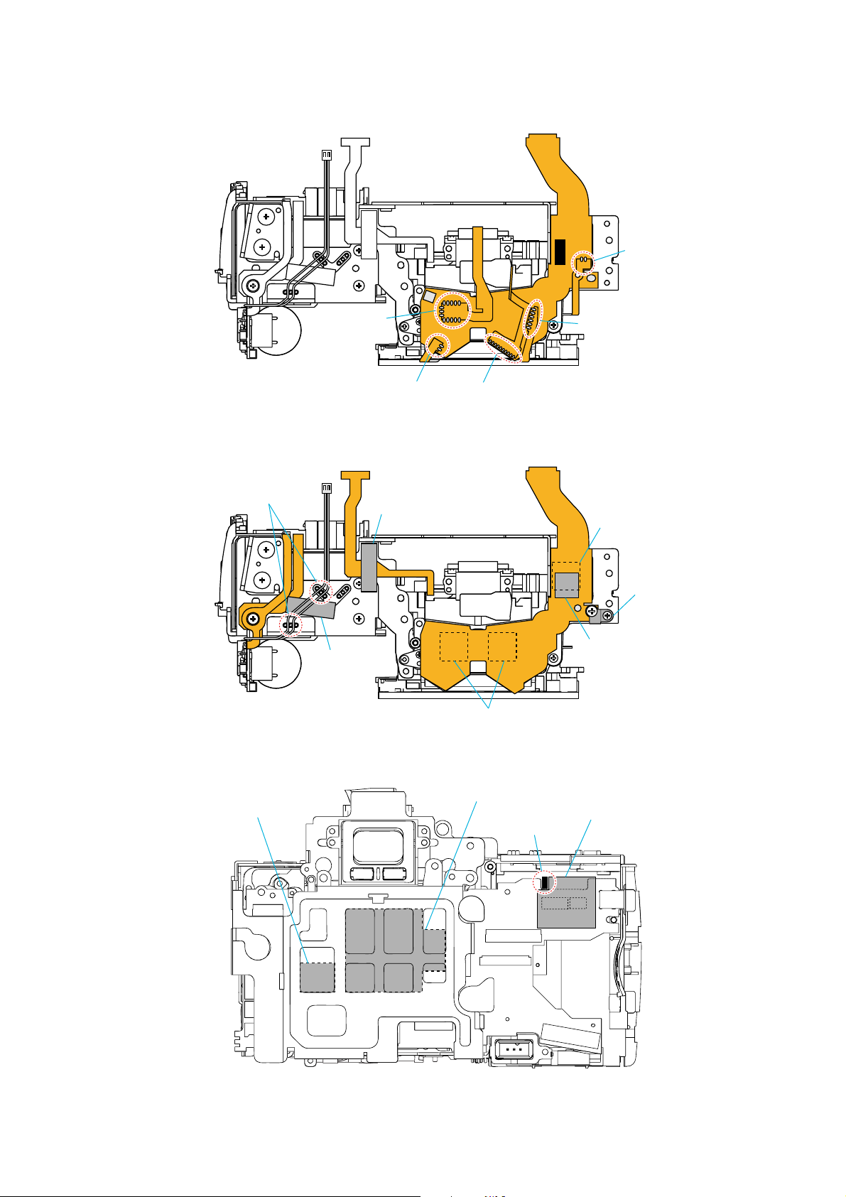
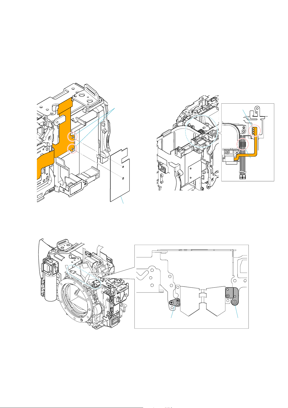
Solder 2 points
Wires arrangement
Solder 13 points
Solder 2 points
FPC Sticking Tape
FPC Sticking Tape
Solder 6 points
Solder 10 points
Fig. 2-1
Top Cover Flexible Fixed Tpe
I/O Flexible Lug Plate
FN Plate Support Tpe
Top Cover Flexible Fixed Tpe
DSLR-A100_L2
Heat Transmission Sheet 1 (S)
Fig. 2-2
Heat Transmission Sheet 2 (L)
FPC Connect Eleprevention Sheet
Boss
Fig. 2-3
2-7
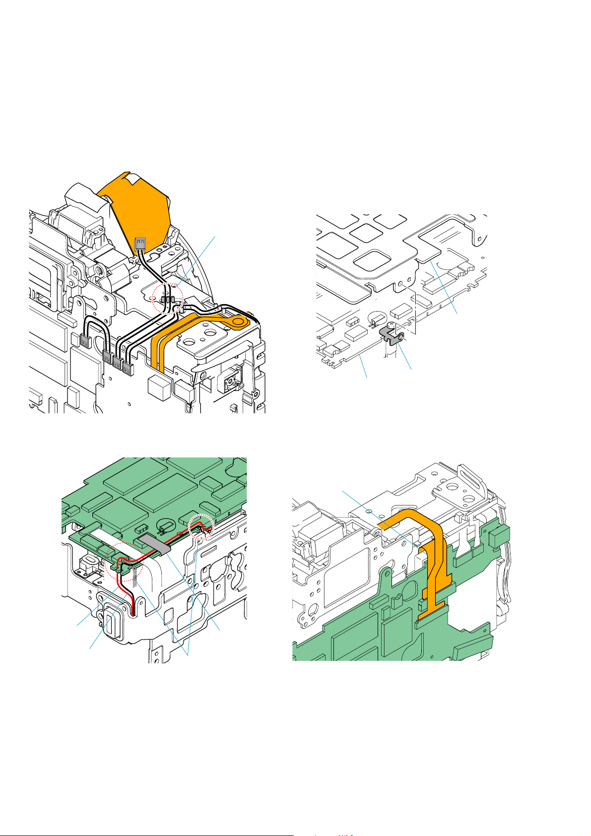
Wires arrangement
Main Chassis
Red
Black
Fig. 2-4
AM-001 Board
Main PC Board Lug Plate
Fig. 2-6
Flexible Board arrangement
Don't tear.
FPC Sticking Tape
Wires arrangement
DSLR-A100_L2
Fig. 2-5
Fig. 2-7
2-8
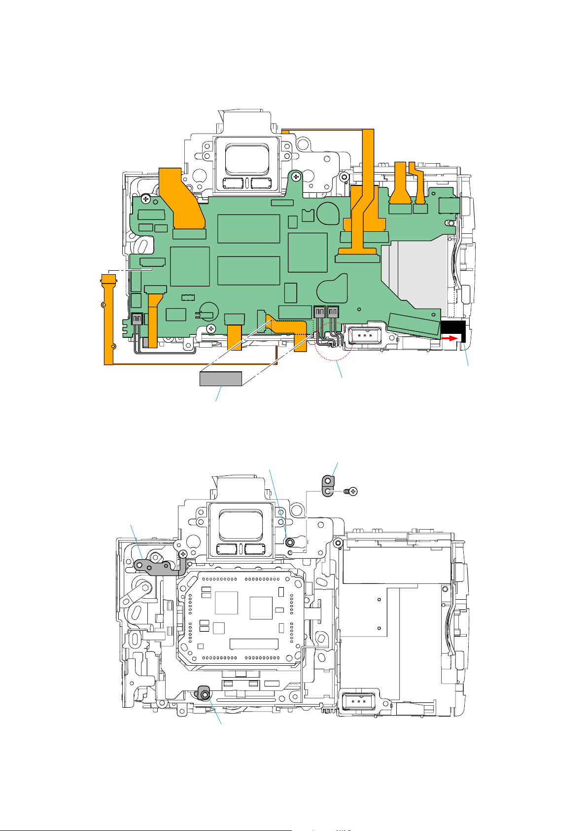
FPC Sticking Tape
AM-001 Board Eject Lever Condition
Wires arrangement
Fig. 2-8
CCD Chassis Lug (2)
PC Board Holding Shaft
Main PC Board Lug Plate
CCD Chassis Lug (1)
DSLR-A100_L2
Fig. 2-9
2-9
2-1-3. HALF SET BODY-2
Follow the disassembly in the numerical order given.
1 Tripod Unit (1-1 to 1-15)
2 Battery Chamber Unit (2-1 to 2-14)
2-12
2-13
2-14 (Fig. 3-3)
EXPLODED VIEW
1-1 (Fig. 3-1)
2-11
1-2
2-8
2-9 (Fig. 3-3)
2-7
2 Battery Chamber Unit
(Fig. 3-2)
2-6
2-10
2-2
2-3
2-5
1-3
2-1 (Fig. 3-2)
1 Tripod Unit
1-9
1-10
1-8
1-6
1-14
1-11
1-15
1-13
2-4
1-4
1-12
1-5
DSLR-A100_L2
1-7
2-10
Boss
CCD Flexible Retainer Sheet
Fig. 3-1 Fig. 3-2
Solder 3 points
Wires
arrangement
DSLR-A100_L2
Penta Protection Lug Plate (1) Penta Protection Lug Plate (2)
Fig. 3-3
2-11
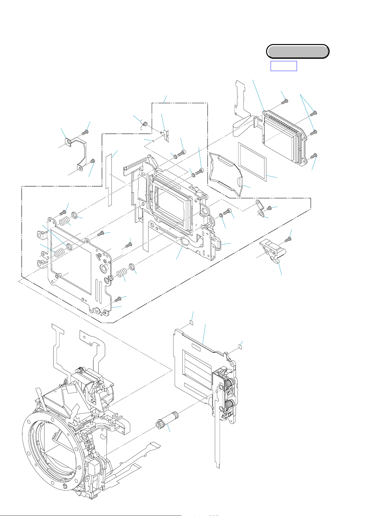
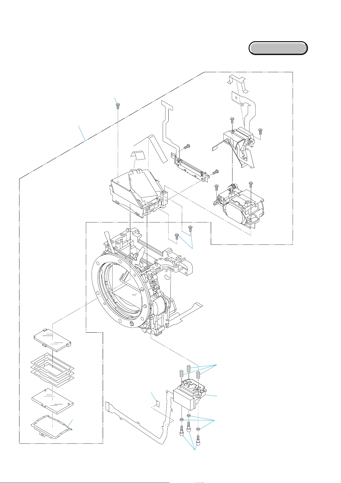
2-1-4. HALF SET BODY-3
Follow the disassembly in the numerical order given.
1 CCD Unit (1-1 to 1-8)
2 Slider Unit (2-1 to 2-27)
3 Shutter Unit (3-1 to 3-3)
2-10
(See page 2-15)
1 CCD Unit
(Fig. 4-1)
EXPLODED VIEW
HELP
1-2
1-3
2-3 (Fig. 4-3)
2-22
2-23
A
B
2-9
2-21
B
2-1
2-2
2-20
A
1-1 (Fig. 4-2)
1-8
2-27
2-8
2-7
C
2-24
2-25
2-6
2-26
1-7
2-13
2-15
2-14
2-16
2 Slider Unit
3-3
2-17
2-18
2-19
1-6
C
1-5
2-11
2-12
2-4
2-5 (Fig. 4-3)
1-4
DSLR-A100_L2
3 Shutter Unit
(See page 2-14)
3-2
3-1
(See page 2-14)
2-12
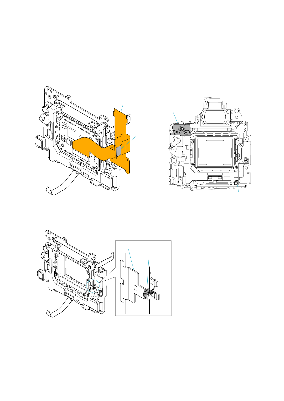
Fig. 4-1
CCD Connecting Mount
PC Board Holding Table (A)
Adhesive Tape
Slider Stop Plate
Fig. 4-3
Fig. 4-2
Ball Retainer
Slider Tension (SP-C)
DSLR-A100_L2
2-13
2-1-5. SHUTTER UNIT INSTALLATION
1. Supply the power (2V, 1A) to the charge motor to rotate it forward so as to move up the mirror completely.
Mirror
DC Power Supply
(2V, 1A)
Charge Motor
Fig. 5-1
2. Insert a screwdriver into a hole in the shutter charge gear, and hold it at 90 degree as shown in Fig. 4-5, and then install the Shutter Unit.
Screwdriver
Shutter Unit
DSLR-A100_L2
Shutter Charge Gera
Screwdriver
Fig. 5-2
2-14

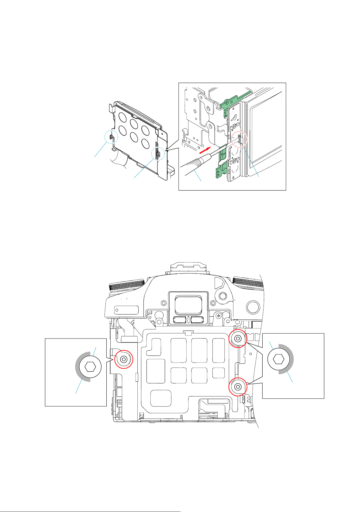
2-1-6. CCD INCLINATION ADJUSTMENT/REPAIR
Check
1. Use a copy stand, or place a mirror on the wall and adjust the accuracy so that the camera is opposed to its mirror image.
2. Use the AE master lens for inspection.
3. Obtain the tilt angle with the Photoshop, and perform as follows according to the angle:
For the angle above +/–1.0 degree, be sure to repair.
For the angle above +/–0.5 degree and less than +/–1.0 degree, repair according to the user's required level.
For the angle below +/–0.5 degree, re-check and it is within the specification.
Adjustment
1. Remove the eccentric pin stopper. (Fig. 6-1)
2. Check, and adjust the hexagonal eccentric pin. (Fig. 6-2)
*The eccentric pin can be rotated 60 degree (CCD tilt 0.42 degree) in clockwise and counterclockwise directions respectiv ely from
the neutral position.
Adjustment exceeding 60 degree is impossible. (Eccentric pin stopper cannot be installed)
If an image tilts toward the lower right, rotate the eccentric pin 60 degree clockwise.
If an image tilts toward the lower left, rotate the eccentric pin 60 degree counterclockwise.
Eccentric Pin
Eccentric Pin Stopper
Eccentric Pin
Fig. 6-1
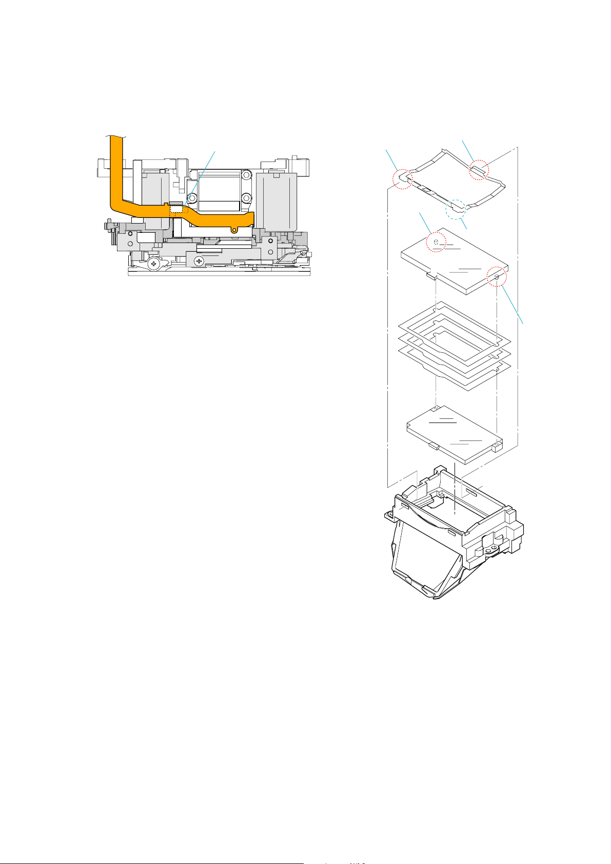
Repair (if the adjusting method failed)
1. Disassemble until the CCD Set can be removed.
2. Cut at two bosses for positional reference and directional reference of the CCD holder and the radiation plate. (Fig. 6-3)
3. Attach an insulation sheet to the terminal of CCD Set. (Prevention of short-circuit with CCD holder)
4. Assemble the CCD Set by shifting it by the amount of play
If an image tilts toward the lower right, shift clockwise the CCD Set by the amount of play.
If an image tilts toward the lower left, shift counterclockwise the CCD Set by the amount of play.
The double-sided adhesive tape on the LPF, if shifted by the amount of play, can be corrected in a range of about +/–0.7 degree
maximum.
In this case, however, prepare the service part "Slider Unit: A-1196-100-A" and modify it as described in step 2 above to make it
as a jig, and then shift the LPF on the jig (for prevention of damage to the Steadyshot Set of user's camera).
5. Assemble up to the exterior.
6. Check the tilt following the checking method.
*If not within +/–0.5 degree, replace the "Slider Unit: A-1196-100-A" and recheck.
7. After the repair completed, perform "CCD Aori and Center Adjustment" and "Steadyshot Sensitivity Adjustment".
Two bosses
(neutral Position)
Fig. 6-2
DSLR-A100_L2
Fig. 6-3
2-15
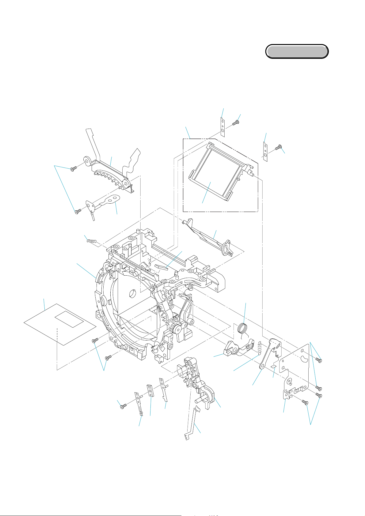
2-1-7. MIRROR BOX UNIT-1
Follow the disassembly in the numerical order given.
1 Penta Unit (1-1 to 1-2)
2 AF Module Unit (2-1 to 2-4)
1-1
1 Penta Unit
EXPLODED VIEW
(Fig. 7-2)
1-2
2-4
2-1 (Fig. 7-1)
2 AF Module Unit
(See page 2-18)
2-3
DSLR-A100_L2
2-2
2-16
AF Module Flexible FixedTape
Fig. 7-1
Claw
Claw
Boss
Claw
Boss
DSLR-A100_L2
Fig. 7-2
2-17
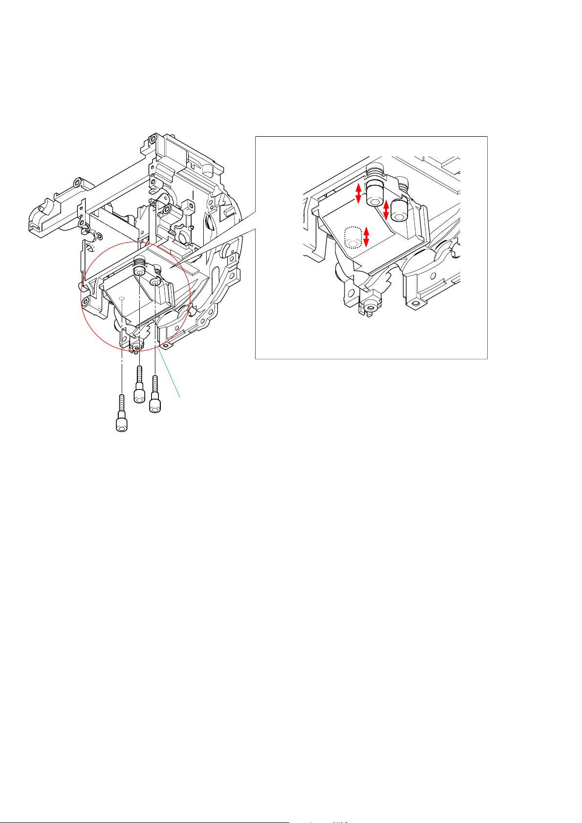
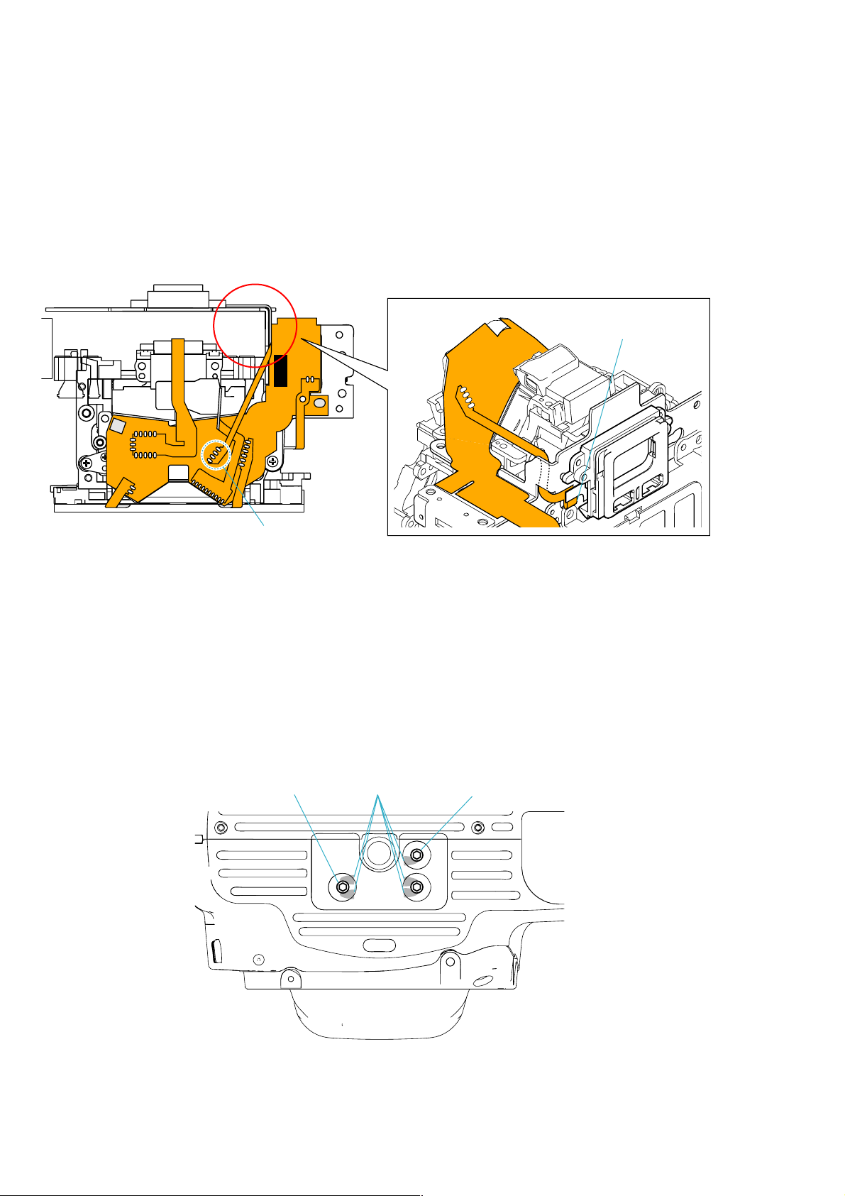
2-1-8. AF MODULE UNIT INSTALLATION
For the AF Module Unit, adjust the height by adjusting the extent
of tightening of three hexagon socket head screws.
Tighten the screws evenly when installing the AF Module Unit.
The AF Module Unit is fixed with three hexagon
socket head screws, washers, and springs.
Fig. 8-1
DSLR-A100_L2
2-18
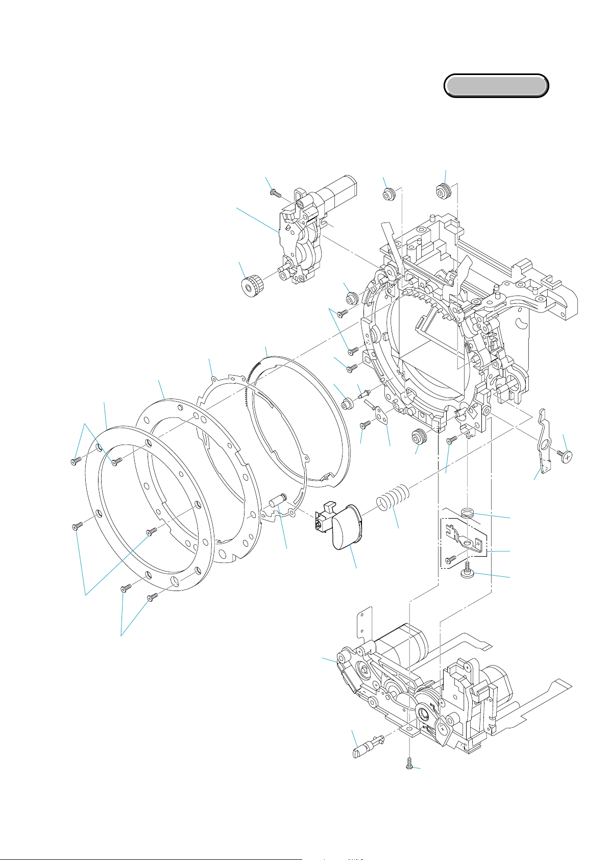
2-1-9. MIRROR BOX UNIT-2
Follow the disassembly in the numerical order given.
1 Iris Ring (1-1 to 1-16)
2 Aperture Unit (2-1 to 2-3)
3 AF Charge Unit (3-1 to 3-10)
EXPLODED VIEW
1-1
1-4
2 Aperture Unit
(Fig. 9-3)
(See page 2-21 to 2-22)
2-3
1 Iris Ring
1-6 (Fig. 9-1)
1-5
2-1
(See page 2-21)
1-13
2-2
3-9
1-11
1-12
3-6
1-14
3-7
1-15
3-4
1-16
1-2
1-3
1-8
3 AF Charge Unit
(See page 2-23)
1-9 (Fig. 9-2)
1-7
1-10
3-8
3-10
3-5
3-3 (Fig. 9-4)
3-2 (Fig. 9-4)
3-1 (Fig. 9-4)
DSLR-A100_L2
2-19
G: G-15
G: G-115
Fig. 9-1 Fig. 9-2
Solder 5 points
Coupler Lever Tention (SP)
Coupler Lever
DSLR-A100_L2
Fig. 9-3
Coupler Lever Shaft
Fig. 9-4
2-20
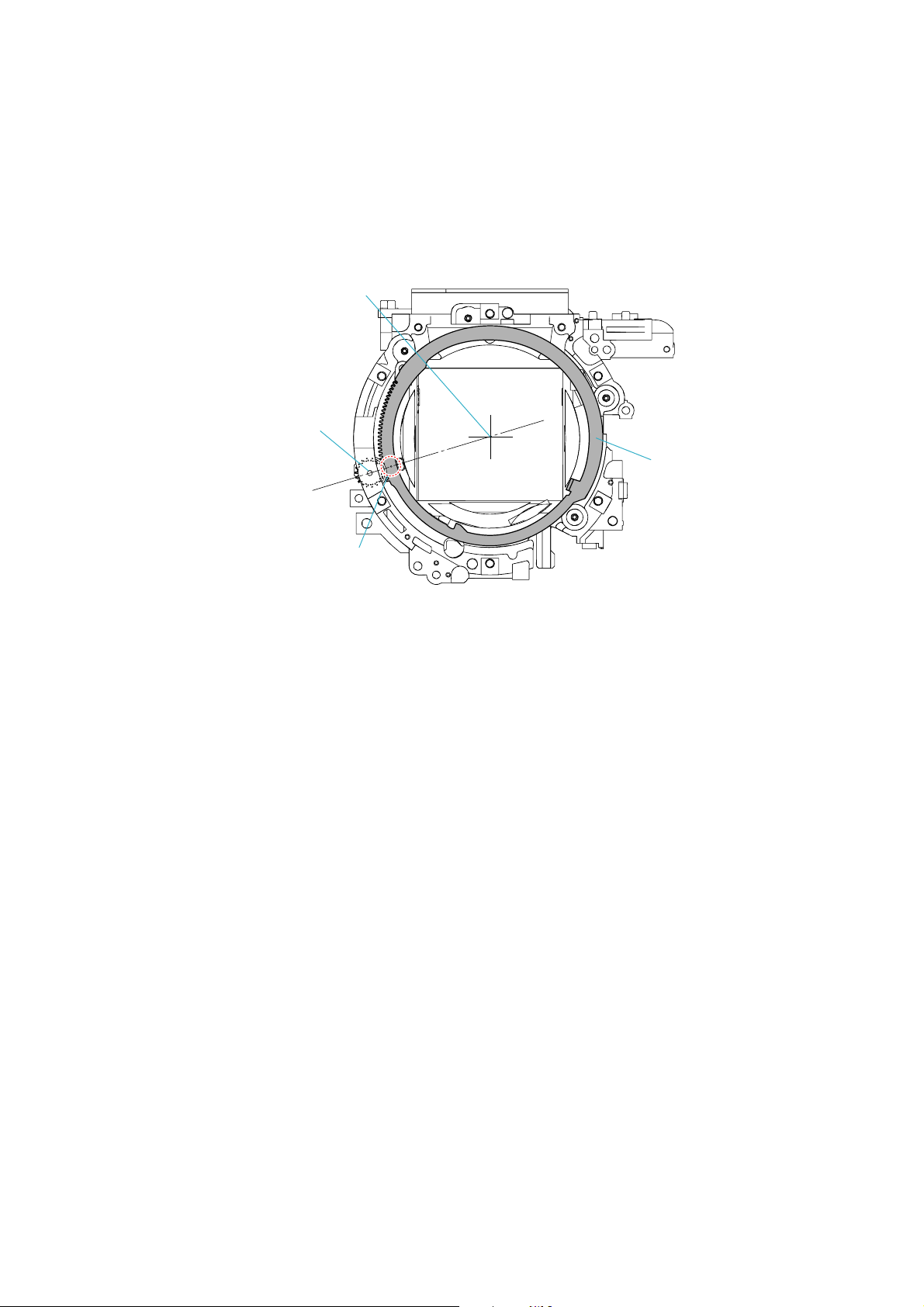
2-1-10. IRIS RING REMOVAL/INSTALLATION
Removal
Rotate the iris ring clockwise, and remove it at the stop position (iris-in end). (Fig. 10-1)
At this time, do not rotate the iris joint gear of the Aperture Unit.
Installation
1. With the Aperture Unit set in the charge position (see "2-1-12. Aperture Unit Charge Position Setting" ), install it on the front frame set.
*The Aperture Unit has been set in the charge position, if it is not removed.
However, the iris ring must be in the removed state (where the iris joint gear is not rotated).
2. Install the iris ring with it's a punch mark aligned with a line that connects the iris joint gear shaft and the optical axis center. (Fig. 10-1)
Optical Axis Center
Iris Joint Gear Shaft
Iris Ring
Punch Mark
Fig. 10-1
2-1-11. APERTURE UNIT INSTALLATION
*The Aperture Unit is supplied by being set in the charge position (initial position), but if this position is disordered when the Aperture Unit is
removed, or if the charge position is to be set again, perform as follows.
*Refer to “2-1-12. Aperture Unit Charge Position Setting” for the confirm method at the charge position.
2-1-12. APERTURE UNIT CHARGE POSITION SETTING
1. Check that the Aperture Unit is in a free state.
2. After confirming that the Aperture Unit is in a free state, rotate the gear by 3 turns.
3. After rotating the gear by 3 turns, set the Aperture Unit where the holes in the gear and the Aperture Unit coincide. This position is the charge
position.
*Refer to “2-1-13. Aperture Unit Free Position Setting” for the setting and the confirm method at the free position.
DSLR-A100_L2
2-21
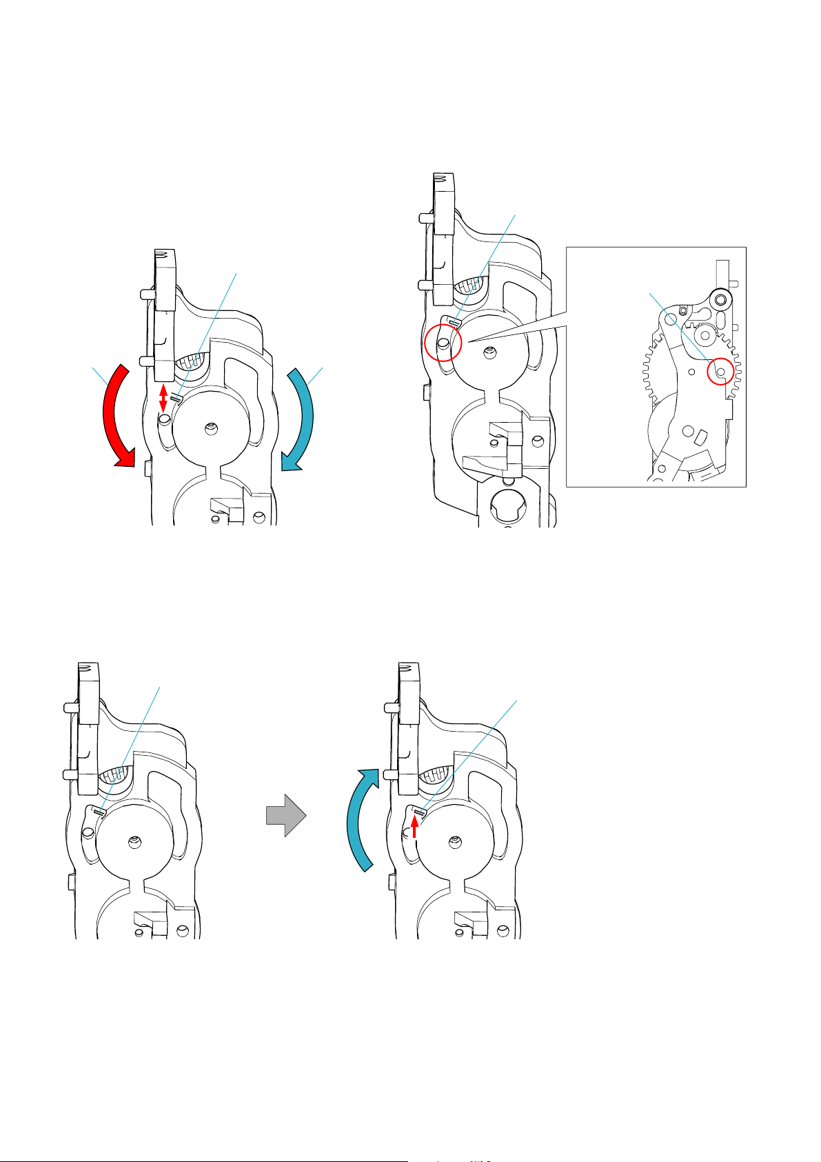
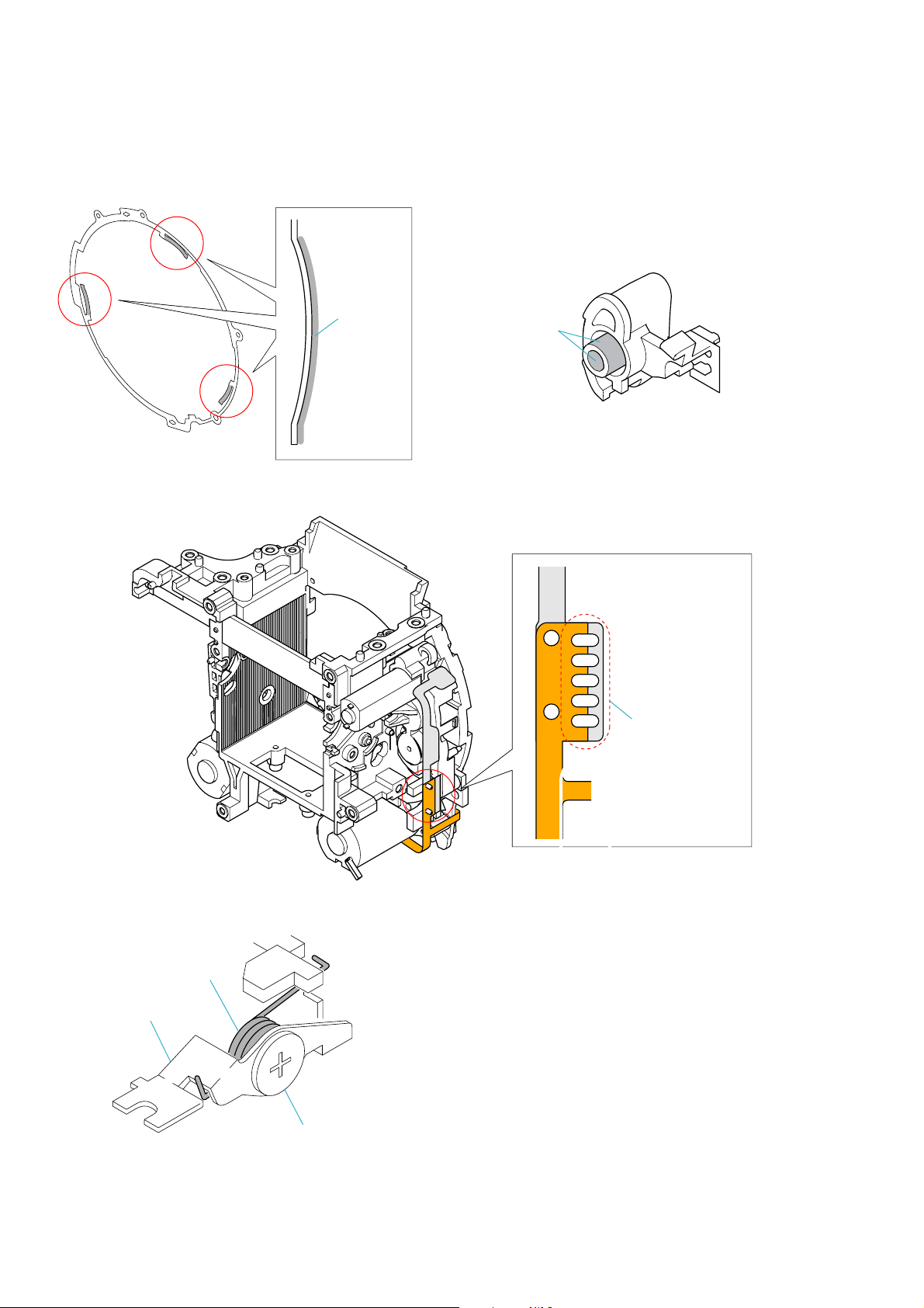
2-1-13. APERTURE UNIT FREE POSITION SETTING
1. Set the Aperture Unit to a free position once, if the gear was rotated accidentally and the charge position is disordered, or if the charge position
was shifted during disassembly. (Fig. 13-1, 13-2, 13-3)
In a free state, a hole in the gear almost
coincides with a hole in the Aperture Unit.
In a free state, the edge of this spring
will move up and down about 1 mm if
the gear is moved a little.
As viewed from gear
(Hole in the gear)
Gear rotating
direction to set
the charge position
Fig. 13-1
First, check the spring edge position.
Gear rotating
direction to make
the unit free
Fig. 13-2
If the edge of spring is located downward,
rotate the gear in the arrow direction to
search a free position.
* In a free position, the edge of spring is
located upward.
DSLR-A100_L2
Note: The spring is deformed and cannot
be used if the gear is rotated too
much from a free state.
Fig. 13-3
2-22

2-1-14. AF CHARGE UNIT INSTALLATION
1. The lever must be in a free state when the AF Charge Unit is installed. (Fig. 14-1)
Check the lever of the AF Charge Unit for position.
If it protrudes outside, rotate the gear in the arrow direction.
Gear
When the lever becomes a free state, it will
retract as shown.
* In this state, install the AF Charge Unit.
Fig. 14-1
DSLR-A100_L2
2-23
2-1-15. MIRROR BOX UNIT-3
Follow the disassembly in the numerical order given.
1 Main Mirror Holder Unit (1-1 to 1-23)
2 Front Frame Unit (2-1 to 2-3)
1 Main Mirror Holder Unit
(Fig. 15-5)
EXPLODED VIEW
1-23
1-22
1-21
1-8
1-11
(Fig. 15-2)
2 Front Frame Unit
2-3
1-10
1-9
1-20
(Fig. 15-4)
2-1 (Fig. 15-5)
2-2
(Fig. 15-6)
1-19
(Fig. 15-3)
DSLR-A100_L2
1-1
1-4
1-5
1-6
1-7
2-24
1-18
(Fig. 15-3)
1-17
(Fig. 15-3)
1-2
1-3
(Fig. 15-1)
1-12
1-15
1-16
(Fig. 15-3)
1-14
1-13
 Loading...