

Page 1
DSLR-A100
SERVICE MANUAL
Ver 1.0 2006.06
Revision History
Revision History
How to use
How to use
Acrobat Reader
Acrobat Reader
Link
Link
SERVICE NOTE
PRINTED WIRING BOARDS
LEVEL 3
US Model
Canadian Model
AEP Model
UK Model
E Model
Australian Model
Hong Kong Model
Chinese Model
Korea Model
Japanese Model
Tourist Model
REPAIR PARTS LIST
SCHEMATIC DIAGRAMS
The components identified by
mark 0 or dotted line with
mark 0 are critical for safety .
Replace only with part number specified.
Les composants identifiés par une
marque 0 sont critiques pour la
sécurité.
Ne les remplacer que par une pièce
portant le numéro spécifié.
DIGITAL SINGLE LENS REFLEX CAMERA
DSLR-A100_L3
Sony EMCS Co.
2006F0500-1
© 2006.6
Published by Kohda TEC9-852-130-11
Page 2

TABLE OF CONTENTS
Section Title Page
1. SERVICE NOTE
1-1. Chemicals ········································································1-1
1-2. Exterior Parts ···································································1-1
1-3. Unleaded Solder ······························································1-1
1-4. Safety Check-out ·····························································1-1
1-5. Note for Replacing Fuse on the AM-001 Board·············· 1-2
1-6. Demagnetization Method ················································1-2
4. PRINTED WIRING BOARDS AND
SCHEMATIC DIAGRAMS
4-2. Schematic Diagrams························································ 4-8
4-3. Printed Wiring Boards ···················································4-26
4-4. Mounted Parts Location ················································4-29
5. REPAIR PARTS LIST
5-2. Electrical Parts List ·······················································5-24
DSLR-A100_L3
— 2 —
Page 3

1. SERVICE NOTE
1-1. CHEMICALS
Some chemicals used for servicing are highly volatile.
Their evaporation caused by improper management affects your health and environment, and wastes resources.
Manage the chemicals carefully as follows.
• Store chemicals sealed in a specific place to prevent from exposure to high temperature or direct sunlight.
•Avoid dividing chemicals into excessive numbers of small containers to reduce natural evaporation.
•Keep containers sealed to avoid natural evaporation when chemicals are not in use.
•Avoid using chemicals as much as possible. When using chemicals, divide only required amount to a small plate from the container and
use up it.
1-2. EXTERIOR PARTS
Be careful to the following points for plastic parts used in this unit.
• Use a piece of cleaning paper or cleaning cloth for cleaning plastic parts. Avoid using chemicals.
Even if you have to use chemicals to clean heavy dirt, don’t use paint thinner, ketone, nor alcohol.
• Insert the specific screws vertically to the part when installing a plastic part.
Be careful not to tighten screws too much.
1-3. UNLEADED SOLDER
This unit uses unleaded solder.
Boards requiring use of unleaded solder are printed with the lead free mark (LF) indicating the solder contains no lead.
(Caution: Some printed circuit boards may not come printed with the lead free mark due to their particular size.)
: LEAD FREE MARK
Be careful to the following points to solder or unsolder.
• Set the soldering iron tip temperature to 350 °C approximately.
If cannot control temperature, solder/unsolder at high temperature for a short time.
Caution: The printed pattern (copper foil) may peel away if the heated tip is applied for too long, so be careful!
Unleaded solder is more viscous (sticky , less prone to flow) than or dinary solder so use caution not to let solder bridges occur
such as on IC pins, etc.
• Be sure to control soldering iron tips used for unleaded solder and those for leaded solder so they are managed separately. Mixing
unleaded solder and leaded solder will cause detachment phenomenon.
1-4. SAFETY CHECK-OUT
After correcting the original service problem, perform the following safety checks before releasing the set to the customer.
1. Check the area of your repair for unsoldered or poorly-soldered connections. Check the entire board surface for solder splashes and
bridges.
2. Check the interboard wiring to ensure that no wires are “pinched” or contact high-wattage resistors.
3. Look for unauthorized replacement parts, particularly transistors, that were installed during a previous repair. P oint them out to the
customer and recommend their replacement.
4. Look for parts which, through functioning, show obvious signs of deterioration. Point them out to the customer and recommend their
replacement.
5. Check the B+ voltage to see it is at the values specified.
6. Flexible Circuit Board Repairing
•Keep the temperature of the soldering iron around 270 °C during repairing.
• Do not touch the soldering iron on the same conductor of the circuit board (within 3 times).
• Be careful not to apply force on the conductor when soldering or unsoldering.
COMPONENTS IDENTIFIED BY MARK 0 OR DOTTED LINE WITH
MARK 0 ON THE SCHEMATIC DIAGRAMS AND IN THE PARTS
LIST ARE CRITICAL TO SAFE OPERATION. REPLACE THESE
COMPONENTS WITH SONY PARTS WHOSE PART NUMBERS
APPEAR AS SHOWN IN THIS MANUAL OR IN SUPPLEMENTS
PUBLISHED BY SONY .
DSLR-A100_L3
Danger of explosion if battery is incorrectly replaced.
CAUTION
Replace only with the same or equivalent type.
SAFETY-RELATED COMPONENT WARNING!!
ATTENTION AU COMPOSANT AYANT RAPPORT
À LA SÉCURITÉ!
LES COMPOSANTS IDENTIFÉS P AR UNE MARQUE 0 SUR LES
DIAGRAMMES SCHÉMA TIQUES ET LA LISTE DES PIÈCES SONT
CRITIQUES POUR LA SÉCURITÉ DE FONCTIONNEMENT. NE
REMPLACER CES COMPOSANTS QUE PAR DES PIÈSES SONY
DONT LES NUMÉROS SONT DONNÉS DANS CE MANUEL OU
DANS LES SUPPÉMENTS PUBLIÉS PAR SONY.
1-1
Page 4

1-5. NOTE FOR REPLACING FUSE ON THE AM-001 BOARD
The caution label for fuse replacing on the AM-001 board is put under the DD-268 boar d. When replacing the fuse, remov e the DD-268 board
and refer to this label.
1-6. DEMAGNETIZATION METHOD
It is easy to receive the influence of the outside magnetism because the slant sensor switch (S624) has the magnet in the inside.
Horizontal and vertical cannot be detected when the influence of magnetism is received, and the display of the LCD panel doesn't change.
Therefore, it is necessary to degauss the screw in the vicinity of the switch.
S624
– AM-001 Board: Side B –
Note it because the user magnetizes set occasionally.
Refer to next page for the demagnetization method.
DSLR-A100_L3
1-2
Page 5
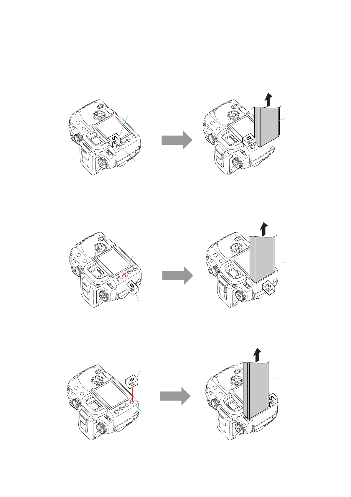
Tools to be prepared:
Push a magnet to the right side of MENU button to
demagnetize.
In the state shown below, operate the demagnetizer for 5 seconds,
and with the demagnetizer operated, detach it in the arrow direction.
At this time, hold the magnet in same position, and remove it after
the demagnetizer was detached.
MENU Button
Magnet
Demagnetizer
Push a magnet to the side of Display button (side surface
of the camera) to demagnetize.
In the state shown below, operate the demagnetizer for 5 seconds,
and with the demagnetizer operated, detach it in the arrow direction.
At this time, hold the magnet in same position, and remove it after
the demagnetizer was detached.
Display Button
Magnet
Demagnetizer
Push a magnet over the Playback button to demagnetize. In the state shown below, operate the demagnetizer for 5 seconds,
and with the demagnetizer operated, detach it in the arrow direction.
At this time, hold the magnet in same position, and remove it after
the demagnetizer was detached.
Magnet
Playback Button
Demagnetizer
Magnet (cover with a tape, etc. for damage prevention)
Demagnetizer
STEP 1:
STEP 2:
STEP 3:
• SLANT SENSOR SWITCH OPERATION INSPECTION
Using the camera already demagnetized, perform the posture switching by five sets, one set comprising “normal posture → Grip up →
Grip down”, to confirm that the LCD display changes over correctly.
DSLR-A100_L3
1-3E
Page 6

Link
Link
4-2. SCHEMATIC DIAGRAMS
AM-001 BOARD (1/5) (CAMERA DSP)
AM-001 BOARD (2/5)
(FLASH MEMORY, SDRAM)
AM-001 BOARD (3/5) (MAIN/SUB CPU)
COMMON NOTE FOR SCHEMATIC DIAGRAMS
AM-001 BOARD (4/5) (ANTI-SHAKE)
AM-001 BOARD (5/5) (CONNECTOR)
DSLR-A100_L3
Page 7

4-2. SCHEMATIC DIAGRAMS
4-2. SCHEMATIC DIAGRAMS
4. PRINTED WIRING BOARDS AND SCHEMATIC DIAGRAMS
4-2. SCHEMATIC DIAGRAMS
THIS NOTE IS COMMON FOR SCHEMATIC DIAGRAMS
(In addition to this, the necessary note is printed in each block)
(For schematic diagrams)
• All capacitors are in µF unless otherwise noted. pF : µ
µF. 50 V or less are not indicated except f or electrolytics
and tantalums.
• Chip resistors are 1/10 W unless otherwise noted.
kΩ=1000 Ω, MΩ=1000 kΩ.
• Caution when replacing chip parts.
New parts must be attached after removal of chip.
Be careful not to heat the minus side of tantalum
capacitor, Because it is damaged by the heat.
• Some chip part will be indicated as follows.
Example C541 L452
22U 10UH
TA A 2520
Precautions for Replacement of Imager
• If the imager has been replaced, carry out all the adjustments
for the camera section.
• As the imager may be damaged by static electricity from
its structure, handle it carefully like for the MOS IC.
In addition, ensure that the receiver is not covered with
dusts nor exposed to strong light.
When indicating parts by reference number, please
include the board name.
Kinds of capacitor
• Constants of resistors, capacitors, ICs and etc with XX
indicate that they are not used.
In such cases, the unused circuits may be indicated.
•Parts with ★ differ according to the model/destination.
Refer to the mount table for each function.
• All variable and adjustable resistors ha ve characteristic
curve B, unless otherwise noted.
• Signal name
XEDIT→ EDIT PB/XREC → PB/REC
• 2: non flammable resistor
• 5: fusible resistor
• C: panel designation
• A: B+ Line
• B: B– Line
• J : IN/OUT direction of (+,–) B LINE.
• C: adjustment for repair.
• A: not use circuit
External dimensions (mm)
Case size
The components identified by mark 0 or dotted line with
mark 0 are critical for safety.
Replace only with part number specified.
Les composants identifiés par une marque 0 sont
critiques pour la sécurité.
Ne les remplacer que par une pièce portant le numéro
spécifie.
DSLR-A100_L3
4-3
Page 8
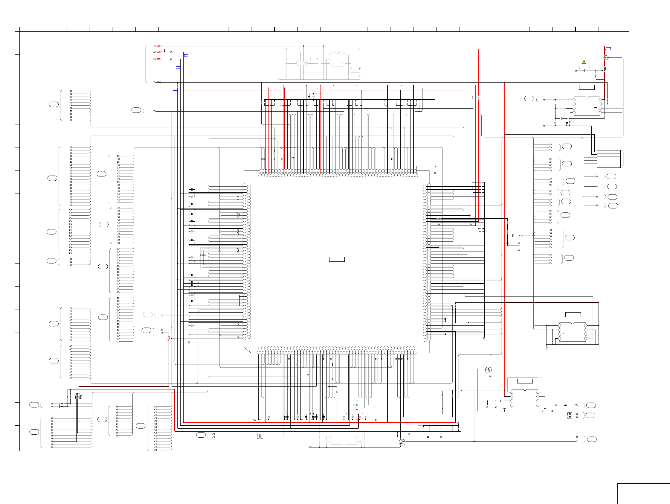
• Refer to page 4-3 for mark 0.
1
AM-001 BOARD (1/5)
A
CAMERA DSP
XX MARK:NO MOUNT
B
C
D
E
F
G
H
I
J
K
L
M
N
O
P
@114
(3/5)
(5/5)
Q
@111
(5/5)
R
05
2 18165 17
LCDD0
LCDD1
LCDD2
LCDD3
LCDD4
@101
LCDD5
(5/5)
LCDD6
LCDD7
LCDCLK
LCDVDX
LCDHDX
MSYSA1
MSYSA2
MSYSA3
MSYSA4
MSYSA5
MSYSA6
MSYSA7
MSYSA8
MSYSA9
MSYSA10
MSYSA11
@102
MSYSA12
(2/5)
MSYSA13
MSYSA14
MSYSA15
MSYSA16
MSYSA17
MSYSA18
MSYSA19
MSYSA20
MSYSA21
MSYSD0
MSYSD1
MSYSD2
MSYSD3
MSYSD4
MSYSD5
MSYSD6
MSYSD7
@103
MSYSD8
(2/5)
MSYSD9
MSYSD10
MSYSD11
MSYSD12
MSYSD13
MSYSD14
MSYSD15
MSYSLWRX
@104
MSYSRDX
(2/5)
MSYSCSX
CCDA1
CCDA3
CCDA5
CCDA7
CCDA9
CCDA11
@105
CCDB1
(5/5)
CCDB3
CCDB5
CCDB7
CCDB9
CCDB11
CCDA0
CCDA2
CCDA4
CCDA6
CCDA8
CCDA10
@106
CCDB0
(5/5)
CCDB2
CCDB4
CCDB6
CCDB8
CCDB10
100k
R101
1
4
FFCD1X
FIOWRX
FFCD2X
FREGX
FWAITX
FRESET
FCE1X
FCE2X
FVS1X
FIORDX
FWEX
23
D110
RB48SKTK
FRDY
FOEX
6
VDD1
DV1
DV2
(5/5)
DV3
LCDD0
LCDD1
LCDD2
LCDD3
LCDD4
LCDD5
LCDD6
LCDD7
LCDCLK
LCDVDX
LCDHDX
MSYSA1
MSYSA2
MSYSA3
MSYSA4
MSYSA5
MSYSA6
MSYSA7
MSYSA8
MSYSA9
MSYSA10
MSYSA11
MSYSA12
MSYSA13
MSYSA14
MSYSA15
MSYSA16
MSYSA17
MSYSA18
MSYSA19
MSYSA20
MSYSA21
MSYSD0
MSYSD1
MSYSD2
MSYSD3
MSYSD4
MSYSD5
MSYSD6
MSYSD7
MSYSD8
MSYSD9
MSYSD10
MSYSD11
MSYSD12
MSYSD13
MSYSD14
MSYSD15
MSYSLWRX
MSYSRDX
MSYSCSX
CCDA1
CCDA3
CCDA5
CCDA7
CCDA9
CCDA11
CCDB1
CCDB3
CCDB5
CCDB7
CCDB9
CCDB11
CCDA0
CCDA2
CCDA4
CCDA6
CCDA8
CCDA10
CCDB0
CCDB2
CCDB4
CCDB6
CCDB8
CCDB10
8
100k
RB101
100k
1234567
R102
FCD1X
FCD2X
FREGX
FWAITX
FRESET
FCE1X
FCE2X
FVS1X
FIORDX
FIOWRX
FRDY
FWEX
FOEX
@107
(2/5)
@108
@109
(2/5)
@110
(2/5)
@112
(5/5)
MDQS0
MDQM0
MDQS1
MDQM1
MDQS2
MDQM2
MCKE
MCLK
MCLKX
MDQS3
MDQM3
MWEX
MCASX
MRASX
MCSX
MBA0
MBA1
MA0
MA1
MA2
MA3
MA4
MA5
MA6
(2/5)
MA7
MA8
MA9
MA10
MA11
MA12
MD0
MD1
MD2
MD3
MD4
MD5
MD6
MD7
MD8
MD9
MD10
MD11
MD12
MD13
MD14
MD15
MD16
MD17
MD18
MD19
MD20
MD21
MD22
MD23
MD24
MD25
MD26
MD27
MD28
MD29
MD30
MD31
FA0
FA1
FA2
FA3
FA4
FA5
FA6
FA7
FA8
FA9
FA10
@115
VREF_DDR
(2/5)
MDQS0
MDQM0
MDQS1
MDQM1
MDQS2
MDQM2
MCKE
MCLK
MCLKX
MDQS3
MDQM3
MWEX
MCASX
MRASX
MCSX
MBA0
MBA1
MA0
MA1
MA2
MA3
MA4
MA5
MA6
MA7
MA8
MA9
MA10
MA11
MA12
MD0
MD1
MD2
MD3
MD4
MD5
MD6
MD7
MD8
MD9
MD10
MD11
MD12
MD13
MD14
MD15
MD16
MD17
MD18
MD19
MD20
MD21
MD22
@117
MD23
(5/5)
MD24
MD25
MD26
MD27
@116
MD28
(5/5)
MD29
MD30
MD31
FA0
FA1
FA2
FA3
FA4
FA5
FA6
FA7
FA8
FA9
FA10
@113
(5/5)
FD0
FD1
FD2
FD3
FD4
FD5
FD6
FD7
FD8
FD9
FD10
FD11
FD12
FD13
FD14
FD15
7 26
R212
0
DV1
R215
0
DV2
R216
0
DV3
C103
0.1u
C104
XX
C105
0.1u
C106
0.1u
C107
0.1u
C108
XX
C109
0.1u
RB103
27
C110
XX
C101
XX
C111
0.1u
C112
0.1u
C113
0.1u
C114
XX
C115
0.1u
C102
XX
PBLK
C116
CV3C
CV3FB
FD0
FD1
FD2
FD3
FD4
FD5
FD6
FD7
FD8
FD9
FD10
FD11
FD12
FD13
FD14
FD15
XX
DGND
@131
9
FD8
FD5
FD9
FD4
FD2
FD10
FD12
FD7
FD15
FD14
FA1
FD13
FD11
FA3
FA5
FA4
FA0
FA7
MCASX
MCSX
MRASX
MWEX
FA6
1234567
FA10
FA8
FA2
8
FWAITX
FCE1X
FCD1X
FA9
FOEX
FRESET
CCDA6
CCDB10
FIOWRX
FRDY
FWEX
FIORDX
CCDA0
CCDA2
CCDB8
FREGX
FCD2X
FCE2X
DM
DP
(5/5)
10
0.1u
C117
R131
100k
FD6
MA9
MA10
MA11
27
R13427R13227R133
M26
M24
N1
M25
FD6
MA9
MA11
N3
N8
N18
N23
N25
P1
P3
P8
P18
P23
P25
R1
R3
R8
R18
R23
R25
T1
T3
T8
T18
T23
T25
U1
U3
U8
U18
U23
U25
V1
V3
V8
V10
V12
V14
V16
V18
V23
V25
W1
W3
W8
W10
W12
W14
W16
W18
W23
W25
Y1
Y3
Y23
Y25
DGND
FD8
FD5
FD9
FD4
FD2
GND_DDR
VDD_DDR_IF_IO
VDD_INT
MA6
VREF_IO
MA7
FD10
FD12
FD7
FD15
GND_INT
VDD_IO
VDD_DDR_IF_IO
GND_DDR
MA8
MA5
MA4
MA3
FD14
FA1
FD13
FD11
GND_IO
VDD_INT
VDD_DDR_IF_IO
GND_DDR
MA2
MA1
MA0
MCLKX
FA3
FA5
FA4
FA0
FA7
VDD_IO
GND_INT
GND_DDR
MCKE
MBA1
MBA0
MCLK
FA6
FA10
FA8
FA2
FWAITX
GND_INT
VDD_DDR_IF_IO
GND_DDR
MRASX
MWEX
MDRAMCSX
MCASX
FCE1X
FCD1X
FA9
FOEX
FRESET
VDD_INT
VDD_IO
GND_IO
CCDA6
VDD_INT
CCDB10
VDD_INT
GND_INT
VDD_IO
GND_DDR
GND_DDR
VDD_INT
BCONF1
SLEEP
VDD_DDR_IF_IO
FIOWRX
FRDY
FWEX
FIORDX
GND_IO
TADCK
GND_INT
CCDA0
CCDA2
GND_IO
CCDB8
CCDC0
GND_IO
CCDD2
GND_IO
VDD_DDR_IF_IO
GND_INT
MDQM1
MDQS1
MDQS1X
FREGX
FVDDEN
FCD2X
FCE2X
GND_DDR
MD14
MDQM0
MDQS0X
3
1
MA10
MSYSXACK1
GND_IO
MSYSRDX
GND_IO
MSYSXCS1X
A2
A4
A3
A5
A1
MSYSRDX
LV5C
BL1C
4
2
LF101
N2
N4
N9
R108
R109 27
R114
R115
R116
R117
R118
R119
R120
N19
N24
27
N26
P2
P4
P9
P19
1
2
4
3
P24
6
5
7
8
P26
RB102
R2
27
R4
R9
R19
27
27
R24
27
22
R26
T2
T4
T9
T19
27
T24
27
22
T26
U2
U4
U9
U19
U24
U26
V2
V4
V9
V11
V13
V15
V17
V19
V24
V26
W2
W4
W9
W11
W13
W15
W17
W19
R125
W24
10
W26
Y2
Y4
Y24
R126
10
Y26
MA6
MA7
MA8
MA5
MA4
MA3
MA2
MA1
MA0
MCLKX
MCKE
MBA1
MBA0
MCLK
MDQM1
MDQS1
MD14
MDQM0
M23
GND_INT
VDD_INT
A6
M19
GND_DDR
MSYSA22
A7
MSYSA19
DGND
C119
LCDCLK
FD0
51
R140
M4
M9
M8
M18
FD0
VDD_IO
GND_IO
VDD_DDR_IF_IO
MSYSA17
MSYSA9
MSYSA19
MSYSA11
A8
A10
A9
A11
MSYSA2
MSYSA9
MSYSA11
MSYSA17
C118
XX
0.1u
FD3
FB112
M3
VCKPX
MSYSA2
A12
MSYSD13
FD1
M2
FD3
MSYSD13
A13
MSYSD8
M1
FD1
MSYSD8
A14
MSYSD4
L26
MA14
MSYSD4
A15
C120
MSYSD0
R253
R254
MA12
27
R146
L25
MA15
MSYSD0
A16
XX
XX
128
XX
L24
L23
MA12
VDD_INT
UDM
UDP
A18
A17
C121
L9
L19
L18
GND_INT
GND_DDR
VDD_DDR_IF_IO
PLL2FLT
PLL3FLT
PLL1FLT
A20
A21
A19
C122
0.0018u
0.0018u
13
Q104
XX
0.1u
C124
BRSO
BRSCK
URXD0
TP160
L4
L3
L8
LSCK1
VCK2B
URXD0
LSOUT1
EJTRST
EJTCK
RSTOUTX
A24
A22
A23
TP152
C123
0.0018u
R255
46
2
5
3
1
R257
XX
10u
C127
0.1u
C126
XX
C129
BRSI
UTXD0
ANSCK
RTCSIO
ANSOUT
MDQS2
L2
K4
K9
K2
K19
K24
K26
L1
K8
K3
K18
K23
K25
MA13
LSIN1
LSIN0
UTXD0
MDQS2
GND_IO
LSOUT0
MDQS2X
VDD_INT
GND_INT
GND_DDR
VDD_DDR_IF_IO
GND_DDR
MD15
VCOMPA
VDDDAC2
EJTDO
FVS2X
FVS1X
MD12
MDQS0
VDD_INT
GND_INT
GND_INT
AA4
A26
AB2
AA2 VDDDAC1
AA26
AA24
A25
AA3
AB1
AA1
AB3
AA23
AA25
XX
R247
MD12
MD15
MDQS0
FVS1X
0.1u
C128
VBUS
XX
0.1u
C130
C125
DGND
XX
C134
MDQS3
K1
LSCK0
VSSDAC1
AB4
MD4
C132
J26
MDQS3
MD4
AB23
C135
0.1u
MD11
0.1u
XX
C131
J25
MDQS3X
MD11
AB24
XX
J24
GND_DDR
VREF_IO
AB25
MD13
R256
XX
C183
XX
J17
J19
J18
J23
GND_IO
PLL3VDDD
USBVSSA1
VDD_DDR_IF_IO
VVREF
VDD_INT
MD13
VSSDAC2
AC2
AB26
AC3
AC1
10u
C133
R244
XX
C136
0.1u
J15
J16
USBVDDA2
GND_IO_W
GP12
GP8
AC4
AC5
TP167
DSI
0.1u
C137
C138
MSYSD5
XX
J14
MSYSD5
GND_INT
AC6
URXD1
J13
VDDWID
GP14
AC7
TP161
CSMAINX
1411
1
2
3
C139
MSYSA5
J11
J12
MSYSA0
GND_INT
IC101
CAMERA DSP
THD
ACLK
AC8
AC9
100
R220
TGCLK
TGHDX
3
4
IN
GND
EN4FB
IC113
XX
0.1u
AV16C
J9
J8
J10
MSYSA5
VDD_INT
GND_IO_W
IC101
MA07169
TSG1
THS2CK
CCDA5
AC12
AC10
AC11
FB109
CCDA8
CCDA5
ADRESC
VOUT
NC
DGND
R208
100
(3/5)
(3/5)
IC112
HD SELECT
IC112
D109
25
VDD1
Q103
3LP02M
B+ SWITCH
BT101
LITHIUM
BATTERY
R209
560
IC110
REAL TIME
CLOCK
IC110
S-35190A-T8T1G
1
INT
2
3
4
(3/5)
(5/5)
3
4
VDD
XOUT
SIO
XIN
SCK
VSS
CS
CN113
1 DV3
2 DGND
UTXD1
3 TxD1
URXD1
4RxD1
UTXD0
5 TxD0
URXD0
6RxD0
ADV1C
ADV1C
SLLKX
SLLKX
DRESCX
DRESCX
CFLED
CFLED
8
Vcc
7
STB
6
SEL
5
Y
VSAG
S2X
S1X
AVJX
VBUS
@134
@129
@130
(5/5)
(3/5)
(5/5)
(3/5)
(5/5)
LEAKC
2
D108
1
RB715W-TL
3
8
R210
10k
RTCSIO
7
RTCSCK
6
CSRTC
5
C174
0.1u
6P
NC
(3/5)
@126
(3/5)
@127
(5/5)
(2/5)
@128
(3/5)
(5/5)
@132
C182
0.1u
15
5
OUT
R258
R259
0
XX
R260
C184
XX
C185
0.1u
ANRSTX
ADV235C
MDQM3
10
R150
J2
J4
H26
J1
J3
SDD7
SDD6
SDCLK
SDCMD
MDQM3
CCDA8
CCDB3
CCDD0
CCDB1
CCDC10
AC14
AC16
AC17
AC15
AC13
CCDB1
CCDB3
R130
100k
XX
C140
IC108
H25
VREF_IO
CCDD4
AC18
MD16
MDQM2
10
R151
H24
MDQM2
CCDD6
AC19
XX
H17
H19
H18
H23
MD16
TMODE2
USBVDDD1
PLL12VSSD
GND_INT
MD3
VDD_DDR_IF_IO
VDD_DDR_IF_IO
AC20
AC22
AC23
AC21
MD3
R152
VIN
VSS
H16
USBVSSA2
MD6
AC24
MD6
XX
XX
XX
E4
VDD_INT
GP9
AE6
TP156
E3
SCEX
ARSYNC
AE7
C150
LCDD4
RSTSUB
E2
VG0
TCPCK
AE8
RTCSCK
C151
MD27
E1
D26
VDCK
MD27
TSG2
TALP2
AE10
AE9
TP162
TGVDX
0.1u
MD28
D25
D24
MD28
GND_INT
VDD_DDR_IF_IO
VDD_DDR_IF_IO
CCDA7
CCDA1
AE12
AE11
CCDA1
CCDA7
CCDB0
R162
100k
D23
D21
D22
VDD_IO
VDD_INT
PLL3VSSA
PLL12VDDA
USBVDDA1
USBVDDA3
MSYSD2
MSYSD7
MSYSD12
MSYSD14
GND_IO_W
MSYSA8
MSYSA16
VDDWID
MSYSUWRX
GND_INT
MSYSXREQ0
TMODE1
PLL3VDDA
USBVSSD1
PLL12VDDD
MSYSD3
MSYSD9
MSYSD15
MSYSA4
MSYSA7
GND_INT
MSYSA13
MSYSA15
MSYSA20
MSYSLWRX
MSYSXWRX
MSYSXRDX
GND_INT
GND_INT
TMODE0
PLL3VSSD
PLL12VSSA
USBVSSA3
USBVSSA4
MSYSD6
MSYSD11
MSYSA1
MSYSA6
MSYSA10
MSYSA12
MSYSA18
MSYSA21
MSYSCSX
MSYSXCS0X
MSYSXACK0
MSYSXREQ1
GND_IO_W
GND_INT
GND_DDR
GND_DDR
GND_DDR
ADPCMDQ
GND_DDR
VDD_INT
GND_DDR
CCDB4
CCDB0
CCDB9
AE14
AE13
AE15
CCDB4
CCDB9
C173
C152
GND_IO
BCONF0
RESETX
CCDA10
GND_IO
CCDD10
CCDD11
CCDC11
XX
0.1u
D20
TMODE3
UREXT
EJTMS
UTEST
CCDD8
CCDD7
CCDD5
CCDD3
CCDD1
CCDC8
CCDC5
CCDC1
CCDB6
CCDB2
CCDA4
TALP4
CCDC9
CCDC6
CCDC3
VDVD
MD29
MD31
VCP0
MD30
EJTDI
VCP1
TSG3
GP15
GP11
GP10
XX
C153
VDD_DDR_IF_IO
VR0
VB0
XO
VR1
TVD
GP7
GP6
GP4
MD1
MD0
0.1u
C175
RB751S-40TE61
DGND
D19
D18
D17
D16
D15
D14
D13
D12
D11
D10
D9
D8
D7
D6
D5
D4
D3
D2
D1
C26
C25
C24
C23
C22
C21
C20
C19
C18
C17
C16
C15
C14
C13
C12
C11
C10
C9
C8
C7
C6
C5
C4
C3
C2
C1
B26
B25
B24
B23
B22
B21
B20
B19
B18
B17
B16
B15
B14
B13
B12
B11
B10
B9
B8
B7
B6
B5
B4
B3
B2
B1
AF26
AF25
AF24
AF23
AF22
AF21
AF20
AF19
AF18
AF17
AF16
AF15
AF14
AF13
AF12
AF11
AF10
AF9
AF8
AF7
AF6
AF5
AF4
AF3
AF2
AF1
AE26
AE25
AE24
AE23
AE22
AE21
AE20
AE19
AE18
AE17
AE16
XX
C176
D103
MSYSD2
MSYSD7
MSYSD12
MSYSD14
MSYSA8
MSYSA16
LCDVDX
LCDD2
R200
10k
3300
MSYSLWRX
TP158
C179
R177
MSYSD3
MSYSD9
MSYSD15
MSYSA4
MSYSA7
MSYSA13
MSYSA15
MSYSA20
MSYSD6
MSYSD11
MSYSA1
MSYSA6
MSYSA10
MSYSA12
MSYSA18
MSYSA21
MSYSCSX
CCDB6
CCDB2
CCDA10
CCDA4
TP166
TP165
TP164
XX
LCDD6
±0.5%
R165
100k
C180
R218
100
±0.5%
LCDD0
LCDD3
LCDD1
LCDHDX
R196
100k
D106
RB751S-40TE61
DTC143EE-TL
LED DRIVE
VBUS
DGND
XX
0.1u
C181
MD29
MD31
TP168
MD30
MD1
MD0
R164
100k
0.1u
0.1u
C178
C177
CP154
0.1u
0.1u
C142
C143
12MXI
MSYSA3
MSYSD1
MSYSD10
H11
H13
H15
H12
H14
XI
MSYSA3
MSYSD1
VDD_INT
MSYSD10
VDD_IO
MD9
VIREF
MD10
GP1
AD2
AC26
AD1
AC25
AD3
MD9
MD10
DSCK
CSDSCX
±0.5%
3k
R154
XX
C141
2
1
MSYSA14
H10
VDDWID
GP13
AD4
XX
C144
H9
MSYSA14
VDD_INT
AD5
H8
MSYSA23
ATSYNC
AD6
CSRTC
C145
AV8C
H4
SDD2
ADPCMDI
AD7
C146
XX
C147
AV6C
MD17
MD18
MD19
MD20
H2
G4
G24
G26
H3
G3
H1
G23
G25
SDD5
SDD1
SDD3
SDD4
MD20
MD18
MD17
MD19
SDWP
THS4CK
TALP1
TALP3
CCDA3
CCDA11
CCDC2
TSG4
CCDA9
CCDB5
AD8
AD10
AD12
AD14
AD16
AD9
AD11
AD13
AD15
TP153
CCDA3
CCDA9
CCDA11
CCDB5
VDHD2
CSTGX
C148
0.1u
XX
0.1u
C149
XX
VDHD1
LCDD7
LCDD5
MD21
MD23
MD22
MD24
MD25
MD26
TP169
F2
F4
F26
MD22
CCDC4
AD19
TP154
F24
F25
MD24
MD21
CCDC7
CCDD9
AD20
AD21
DTC144EMT2L
VBUS DETECT
F23
VDD_INT
VDD_INT
AD22
E5
E24
E26
F1
F3
E23
E25
VB1
VG1
SDD0
VDHD
MD26
MD23
MD25
VDD_IO
GND_DDR
MD2
MD8
GP0
VIOUT
GP2
MD5
MD7
GP5
GP3
AE2
AE4
AD24
AD26
AE1
AE3
AE5
AD23
AD25
TP155
TP163
MD2
MD5
MD7
MD8
BRCSMAINX
CSDATAX
R163
47k
Q101
G2
G1
SDCD
SDPOEN
CCDB11
CCDB7
AD18
AD17
CCDB7
CCDB11
2120
4.7uH
L101
4.7uH
L102
C155
10u
C156
0.1u
C157
0.1u
C158
0.1u
C159
0.1u
BRFWE
C160
0.1u
C161
XX
C154
XX
C162
0.1u
C163
10u
DRESCX
LV3C
LV8C
ADV1C
CSADX
UTXD1
DSOUT
SLLKX
CSLCDX
C164
XX
CSBRX
DGND
CFLED
Q102
DGND
R197
75
±0.5%
±0.5%
22 243 19
R241
3900
R250
0
X101
12MHz
C170
5p
BH76812FVM-TR
1
C1
2
VCC
C165
1u
3
VIN
4
STBY
R199
C166
75
4.7u
FB108
C172
5p
DGND
IC111
VIDEO AMP
IC111
@133
(3/5)
12MXI
234
CP153
32KHZ
DGND
ANSOUT
TGHDX
CSADX
TGCLK
ANSCK
ANRSTX
CSTGX
TGVDX
BRCSMAINX
BRSI
BRFWE
BRSCK
BRSO
LV5C
CSLCDX
LV3C
BL1C
LV8C
AV16C
AV8C
AV6C
LEAKC
CSDSCX
CSDATAX
DSOUT
DSCK
DSI
CSMAINX
ADRESC
RSTSUB
ADV235C
CSBRX
VDHD1
VDHD2
C167
1u
8
C2
7
-VCC
6
GND
5
VOUT
R204
XX
R203
0
X102
32.768kHz
C171
C169
10p
XX
ANSOUT
@118
TGHDX
(5/5)
CSADX
TGCLK
ANSCK
@119
ANRSTX
(5/5)
CSTGX
TGVDX
BRCSMAINX
@120
BRSI
BRFWE
BRSCK
@121
BRSO
LV5C
@122
CSLCDX
(5/5)
LV3C
BL1C
LV8C
@123
AV16C
(5/5)
AV8C
AV6C
LEAKC
CSDSCX
CSDATAX
@124
DSOUT
DSCK
DSI
CSMAINX
ADRESC
RSTSUB
@125
ADV235C
(3/5)
CSBRX
HD74ALVC2G157USE-E
1
A
2
B
3
Y
4
R251
1M
GND
R252
1M
DGND
R206
75
FB110
±0.5%
C168
1u
DGND
2
1
RB48SKTK
DSLR-A100_L3
4-8
AM-001 (1/5)
Page 9

1 165
4 13
6
10
15
173
1992 1881411712
20
21
AM-001 BOARD (2/5)
A
FLASH MEMORY, SDRAM
XX MARK:NO MOUNT
B
C
D
E
F
G
H
@103
I
J
K
L
M
N
O
P
05
DSLR-A100_L3
DV2
R804
IC201
DDR SDRAM
IC201
EDD5116AFTA-6B-E-TR
1
RB801
MD0
MD1
MD2
MD3
MD4
MD5
MD6
MD7
DV3
(5/5)
MSYSCSX
@104
MSYSRDX
(1/5)
MSYSLWRX
MSYSD8
MSYSD7
MSYSD5
MSYSD2
TP203
IC203
MSYSA14
MSYSA17
E6
TP205
MSYSA5
A16F1CE#
MSYSA18
MA10
MA11
MA12
MSYSD0
MA10
MSYSA1
TP206
E1
E2
A0
DQ0E3DQ2E4DQ5E5DQ7
D6
D5
D4
D3
D2
D1
C6
C5
C4
C3
C2
C1
MDQS0
MDQM0
MDQS1
MDQM1
MDQS2
MDQM2
MCLKX
MDQS3
MDQM3
MCASX
MRASX
MSYSA16
MSYSA12
MSYSA20
MSYSA21
MSYSA6
MSYSA2
MSYSA15
MSYSA11
MSYSA19
MSYSA7
MSYSA3
MCKE
MCLK
MWEX
MCSX
MBA0
MBA1
A15
A11
A19
A20
A5
A1
A14
A10
NC
A18
A6
A2
MSYSA13
MSYSA9
MA0
MA1
MA2
MA3
MA4
MA5
MA6
MA7
MA8
@107
MA9
(1/5)
MA0
MA1
MA2
MA3 MA4
MD16
MD17
MD18
MD19
MD20
MD21
MD22
MD23
MA0
MA2
MA3
MSYSD10
MSYSD12
MSYSD14
MSYSD0
MSYSD1
MSYSD2
MSYSD3
MSYSD4
MSYSD5
MSYSD6
MSYSD7
MSYSD8
(1/5)
MSYSD9
MSYSD10
MSYSD11
MSYSD12
MSYSD13
MSYSD14
MSYSD15
MSYSD0
MSYSD1
MSYSD2
MSYSD3
MSYSD4
MSYSD5
MSYSD6
MSYSD7
MSYSD8
MSYSD9
MSYSD10
MSYSD11
MSYSD12
MSYSD13
MSYSD14
MSYSD15
@109
@102
(1/5)
MSYSA1
MSYSA2
MSYSA3
MSYSA4
MSYSA5
MSYSA6
MSYSA7
MSYSA8
MSYSA9
MSYSA10
MSYSA11
MSYSA12
MSYSA13
MSYSA14
MSYSA15
MSYSA16
MSYSA17
MSYSA18
MSYSA19
MSYSA20
MSYSA21
MD0
MD1
MD2
MD3
MD4
MD5
MD6
MD7
MD8
MD9
MD10
MD11
MD12
MD13
MD14
MD15
MSYSA1
MSYSA2
MSYSA3
MSYSA4
MSYSA5
MSYSA6
MSYSA7
MSYSA8
MSYSA9
MSYSD9
MSYSA10
MSYSD11
MSYSA11
MSYSA12
MSYSD13
MSYSA13
MSYSD15
MSYSA14
MSYSA15
MSYSD1
MSYSA16
MSYSA17
MSYSD3
MSYSD4
MSYSA18
MSYSD6
MSYSA19
MSYSA20
MSYSA21
@128
MD0
MD1
MD2
MD3
MD4
MD5
MD6
MD7
@110
MD8
MD9
MD10
MD11
MD12
MD13
MD14
MD15
(1/5)(1/5)
DV3
OE#
G1
TP202
DQ9
G2
DQ11
TP201
DGND
DRESCX
G3
Vcc
G4
DQ13
G5
DQ15/A-1
G6
Vss
H1
DQ1
H2
DQ3
H3
DQ4
H4
DQ6
H5
Vss
H6
MD16
MD17
MD18
MD19
MD20
MD21
@108
MD22
MD23
(1/5)
MD24
MD25
MD26
MD27
MD28
MD29
MD30
MD31
C801
0.1u
(1/5)
(3/5)
MD16
MD17
MD18
MD19
MD20
MD21
MD22
MD23
MD24
MD25
MD26
MD27
MD28
MD29
MD30
MD31
F2
F3
F6
DQ8
DQ10F4DQ12F5DQ14
BYTE#
IC203
FLASH MEMORY
S29AL032D70BFI03-92
A3A2A7A3RY/BY#A4WE#A5A9A6A13B1A4B2A17B3WP#/ACCB4RESET#B5A8B6A12
A1
TP204
MSYSA10
MSYSA8
MSYSA4
MA0
MA1
MA2
MA3
MA4
MA5
MA6
MA7
MA8
MA9
MA10
MA11
MA12
56
1
2
3
4
5
6
7
8
RB802
56
1
2
3
4
5
6
7
8
R814
56
RB805
56
1
2
3
4
5
6
7
8
RB806
56
2
1
4
3
6
5
8
7
R823
56
DGND
VDD
C803
0.1u
2
DQ0
3
VDDQ
C804
0.1u
4
DQ1
5
DQ2
6
VSSQ
7
DQ3
8
DQ4
9
VDDQ
C805
0.1u
DQ5
10
DQ6
11
VSSQ
12
DQ7
13
NC
14
VDDQ
15
C806
0.1u
LDQS
16
NC
17
VDD
18
C807
0.1u
NC
19
LDM
20
/WE
21
/CAS
22
/RAS
23
/CS
24
NC
25
BA0
26
BA1
27
A10(AP)
28
A0
29
A1
30
A2
31
A3
32
VDD
33
C808
0.1u
1
VDD
C809
0.1u
2
DQ0
3
VDDQ
C810
0.1u
4
DQ1
5
DQ2
6
VSSQ
7
DQ3
8
DQ4
9
VDDQ
C811
0.1u
DQ5
10
DQ6
11
VSSQ
12
DQ7
13
NC
14
VDDQ
15
C812
0.1u
LDQS
16
NC
17
VDD
18
C813
0.1u
NC
19
LDM
20
/WE
21
/CAS
22
/RAS
23
/CS
24
NC
25
BA0
26
BA1
27
A10(AP)
28
A0
29
A1
30
A2
31
A3
32
VDD
33
C814
0.1u
IC202
DDR SDRAM
IC202
EDD5116AFTA-6B-E-TR
VSS
66
DQ15
65
VSSQ
64
DQ14
63
DQ13
62
VDDQ
61
DQ12
60
DQ11
59
VSSQ
58
DQ10
57
DQ9
56
VDDQ
55
DQ8
54
NC
53
VSSQ
52
UDQS
51
NC
50
VREF
49
VSS
48
UDM
47
/CK
46
R825
CK
45
CKE
44
NC
43
A12
42
A11
41
A9
40
A8
39
A7
38
A6
37
A5
36
A4
35
VSS
34
VSS
66
DQ15
65
VSSQ
64
DQ14
63
DQ13
62
VDDQ
61
DQ12
60
DQ11
59
VSSQ
58
DQ10
57
DQ9
56
VDDQ
55
DQ8
54
NC
53
VSSQ
52
UDQS
51
NC
50
VREF
49
VSS
48
UDM
47
/CK
46
CK
45
CKE
44
NC
43
A12
42
A11
41
A9
40
A8
39
A7
38
A6
37
A5
36
A4
35
VSS
34
4-9
0
RB803
56
MD15
1
2
3
4
5
6
7
8
MD14
MD13
C815
0.1u
C816
0.1u
200
C817
0.1u
C818
0.1u
R826
200
MD12
RB804
56
MD11
1
2
3
4
5
6
7
8
MD10
MD9
MD8
R835
56
0.1u
C819
MA12
MA11
MA9
MA8
MA7
MA6
MA5
R824
0
RB807
56
MD31
7
8
5
6
3
4
1
2
MD30
MD29
MD28
RB808
56
MD27
7
8
5
6
3
4
1
2
MD26
MD25
MD24
R844
56
0.1u
C820
DGND
MA12
MA11
MA9
MA8MA10
MA7
MA6MA1
MA5
MA4
C821XXC823
XX
C822
R845
100k
±0.5%
XX
R847
10
C825
R846
1u
100k
±0.5%
XX
C824
IC205
REFERENCE
VOLTAGE
GENERATOR
IC205
XC221A1100MR
1
VOUT
VSS
2
VDD
3
IN+4IN-
C826
4.7u
DV2
(5/5)
DV3
VREF_DDR
5
DGND
@115
(1/5)
AM-001 (2/5)
Page 10

• Refer to page 4-3 for mark 0.
AM-001 BOARD (3/5)
A
MAIN/SUB CPU
XX MARK:NO MOUNT
B
C
D
VDD1
(5/5)
@137
(5/5)
DETX
TRIG
FULL
FCHG
E
F
COM0
COM1
@153
(5/5)
@126
(1/5)
@141
(5/5)
COM2
COM3
SEG0
SEG1
SEG2
SEG3
SEG4
SEG5
SEG6
SEG7
SEG8
SEG9
SEG10
SEG11
SEG12
SEG13
SEG14
SEG15
SEG16
SEG17
SEG18
SEG19
ADV1C
IFBL_K
RJU003N03T1
BACKLIGHT
ON/OFF
Q308
G
H
I
J
K
L
M
N
O
VDD1
(5/5)
P
Q
R
S
05
DSLR-A100_L3
TP303
(5/5)
TRIG
FULL
FCHG
COM0
COM1
COM2
COM3
SEG0
SEG1
SEG2
SEG3
SEG4
SEG5
SEG6
SEG7
SEG8
SEG9
SEG10
SEG11
SEG12
SEG13
SEG14
SEG15
SEG16
SEG17
SEG18
SEG19
D304
RB751S-40TE61
R323
33
PGND
RB301
100k
1
7
3
456
2
8
KEY4X
KEY7X
KEY6X
KEY5X
R317
100k
Q309
HN1L02FU(TE85R)
BATTERY
CHARGE DETECT
MV6
R308
680
123
R371
10k
CP339
RB302
100k
1234567
EXBRRXD
R316
100k
5
EXBRTXD
3 12 25131
RB521S-30-TE61
IC305
4.5V REG
IC305
S-812C45BPI-C4ZTFG
IC312
VOLTAGE
DETECT
IC312
BD4830FVE
R326
R327
0
100k
VCC1C
R369
1k
KEY0X
DV1C
KEY1X
XXR307
KEY2X
KEY3X
S1X
X303
4MHz
S2X
SLLKX
SFLDX
FEN
DGND
C335
XX
SMX
8
EXBRSCK
DGND
D309
RB521S-30-TE61
6
3
2
4
1
R332
100k
D318
RB521S-30-TE61
DGND
@136
48 19
D321
1SS400TE-61
CP303
R328
100k
FLWX
FLWX
(5/5)
KEY4X
D322
EXBRRXD
EXBRTXD
EXBRSCK
BRSO
BRSI
BRSCK
GSW
HPFSWX
R304
1M
C313
R315
100k
KEY4X
DGND
R361
1
VOUT
2
SUB
3NC4
R329
100k
0.1u
CP337
CP338
CP348
SOUT
SIN
TP305
C327
0.1u
BAT_C
D316
RB48SKTK
@138
VIN
560
VDD
GND
@130
(1/5)
(5/5)
2
3
(5/5)
C315
0.1u
4
5
6
VIN
VSS
ON/OFF
VIN3VOUT
NC
2
1
C317
4.7u
R360
VDD1
100k
C319
1u
5
C331
1u
V0
91
V1
92
V2
93
V3
94
EXBRRXD
95
EXBRTXD
96
EXBRSCK
97
BRSO
98
BRSI
99
BRSCK
100
VCC1C
101
DV1C
102
KEY0x
103
KEY1x
104
VCC
105
VSS
106
X1
107
X0
108
KEY2x
109
KEY3x
110
S1x
111
S2x
112
SLLKx
113
SFLDx
114
FLED
115
IFBL
116
GSW
117
HPFSWx
118
SOUT
119
SIN
120
DGND
CSBRX
BRCSMAINX
R393
R370
100k
100k
VBUS
AVJX
DGND
PUPCN3X
1
4
SPVX
SAFMFX
@139
(5/5)
IC317
3.3V REG
IC317
S-812C33BPI-C4NTFG
R398
10
TP314
R392
100k
R391
100k
90
RESET
SCK2BATRxD3BATTxD4USBDETx5PUPCN4x6PUPCN5x7RESCx8SDIAL1x9SDIAL2x10SDCJx11BRPW_P112BRPW_P213X0A14X1A15VCC3B16VSS17VCC318BRPW_Y119BRPW_Y220KEY4x21KEY5x22KEY6x23KEY7x24CSBRx25CSDSPx26SMx27DRESCx28FCHG29FIND30CSLNSx
1
SCK
D306
XX
ASACTVX
R394
100k
Q339
XX
2
F3
F3
PUPCN3X
@146
@125
(1/5)
Q340
DTC144EMT2L
RESET
RESETX
PUPCN3X
PUPCN2X
EXBRMD2
COM3
COM2
COM1
COM0
83
87
COM084COM185COM286COM3
MOD288MOD189MOD0
1k
R362
1kR345
1k
RESET_MX
R346
PUPCN4X
PUPCN5X
SDIAL1X
SDIAL2X
RESETX
C347
0.001u
6
3
5
1
4
BRSI
BRFWE_2
BRCSMAINX
BRSI
BRFWE
BRCSMAINX
@121
@120
(1/5)
F2
BZ
TRX
SFLDX
SDIAL1X
SDIAL2X
F2
BZ
TRX
SFLDX
SDIAL1X
SDIAL2X
@147
(5/5)
(5/5)
C378
22u
DV235C
PUPCN1X
PUPCN0X
79
PUPCN0x80PUPCN1x81PUPCN2x82PUPCN3x
ANTI-SHAKE CONTROLLER,
BRPW_P1
BRPW_P2
C348
0.001u
BRSO
BRSCK
BRSO
BRSCK
(1/5)
(5/5)
S2X
@129
(1/5)
(5/5)
5
6
VIN
ON/OFF
NC2VIN3VOUT
1
CSBRX
ADRESC
RSTSUB
ADV235C
BRFWE
ASACTVX
75
77
78
BRFWE
ASACTVx
IC303
SUB CPU
IC303
MB91F233LPFF-G-91-E1
1M
R302
32KHZ
SDCJX
Q341
XX
EXBRSCK
EXBRMD2
EXBRSCK
EXBRMD2
@155
(5/5)
S1X
S1X
S2X
4
VSS
C304
4.7u
RB751S-40TE61
BRCSMAINX
0.1u
C312
74
VCC76VSS
BRSCMAINx
EXBRTXD
EXBRRXD
EXBRTXD
SMX
PUPCN5X
SMX
@148
(5/5)
D317
32KHZ
PSSW
73
BRPW_Y1
EXBRRXD
PUPCN5X
PSSW
PUPCN4X
MONBA
72
BRPW_Y2
PUPCN4X
BRFWE_2
MONBA
CLIM
71
KEY4X
HPFSWX
1CMG_1
70
CLIM
KEY5X
@133
GSW
HPFSWX
@154
KEY7X
@152
VCC1
(5/5)
VDD2
R319
33
3.3V
R320
XX
ADRESC
R397
1k
CSBRX
CP334 CP335
COM3
SEG19
SEG18
SEG17
SEG16
SEG15
SEG14
69
1CMG
DV2356C
CSBRX
CSDSPX
KEY6X
KEY7X
SMX
FCHG
(1/5)
GSW
(4/5)
KEY7X
(5/5)
R364
CLIM
PSSW
MONBA
AD_VMON
AD_GOUT_Y
AD_ICVREFM
CLIM
PSSW
MONBA
AD_VMON
AD_GOUT_Y
AD_ICVREFM
@159
KEY1X
KEY2X
KEY3X
KEY5X
KEY6X
PUPCN2X
KEY5X
KEY6X
KEY3X
KEY2X
KEY1X
PUPCN2X
@151
(5/5)
SEG18
SEG13
FIND
1k
AD_GOUT_P
KEY0X
SEG12
61
CSLNSX
R366
100k
AD_POUT_Y
AD_GOUT_P
KEY0X
SEG1262SEG1363SEG1464SEG1565SEG1666SEG1767SEG1868SEG19
AD_ICVREFM
R338
100k
RESETX
AD_POUT_P
AD_POUT_Y
(4/5)
AD_VMON
AD_GOUT_Y
AD_GOUT_P
AD_POUT_Y
AD_POUT_P
DA_GREF_Y
DA_GREF_P
D305
XX
R365
1k
DA_GREF_Y
AD_POUT_P
DV235C
DV235C
@140
6
ON/OFF
NC2VIN3VOUT
1
C382
10u
1
2
SEG11
SEG10
SEG9
SEG8
SEG7
SEG6
SEG5
SEG4
SEG3
SEG2
SEG1
SEG0
VCC3IO
VSS
FULL
BCAN
AVSS
AVRH
AVCC
RW
WAKEx
CFDETx
SMX
DA_GREF_P
DA_GREF_P
DA_GREF_Y
BAT_C
VCC1C
BAT_C
(5/5)
9
R318
100k
4
5
VIN
VSS
C383
4.7u
S624
SLANT
SENSOR
D6B-2L
HORIZONTAL/VERTICAL
5
POSITION DETECT
DGND
60
59
58
57
56
55
54
53
52
51
50
49
48
47
46
45
44
43
42
41
40
39
38
37
36
35
34
33
32
31
D303
RB751S-40TE61
CP350
BRPW_Y1
BRPW_Y2
BRPW_Y1
BRPW_Y2
@158
(4/5)
DV1C
DV1C
VCC1C
BRPW_P1
BRPW_P2
BRPW_P2
SDCJX
PUPCN1X
SDCJX
@150
(5/5)
DGND
3
4
0.1uC310
BRPW_P1
PUPCN0X
PUPCN1X
S-812C33BPI-C4NTFG
VAE33REG
SEG11
SEG10
SEG9
SEG8
SEG7
SEG6
SEG5
SEG4
SEG3
SEG2
SEG1
SEG0
C309
0.1u
AD_VMON
AD_ICVREFM
AD_GOUT_Y
AD_GOUT_P
AD_POUT_Y
AD_POUT_P
DA_GREF_Y
DA_GREF_P
@128
(1/5)
(2/5)
PUPCN0X
IC318
ADRESC
DRESCX
@163
3.3V REG
(5/5)
10
DGND
SIN
VCC
GND
VP_F
Q307
XX
R313
XX
PGND
R339
100k
CSDSPX
FM2
74
75
FM2
FM1
76
CM2
77
CM1
78
CSDSPx
79
CSLNSx
80
BC1
81
CSLEDx
82
CSBCKx
83
CSLMx
84
CSFLx
85
CSIOx
86
SVH1
87
SVH2
88
TEMP2
89
AFPM
90
AFMPR
91
TEMP
92
LMOUT
93
AVSS
94
VOUT
95
VREF
96
AVCC
97
ADTa
98
RST
99
IST
100
PRADJ2NC3FP24FP15AFP1a6BYTE7CNVSS8XCIN9XCOUT10RESET11XOUT12VSS13XIN14VCC15NMI16CSMAINx17SCAM1x18XONx19AFP220AFP1b21MFP2x22MFP1x23LVPCL24LEDPWM25SCAM2x
1
R336
XX
PRADJ
8
C301
7
NC
0.1u
6
NC
5
F3H
C341
0.1u
F3L
C320
4700p
F2OUT
DGND
F2IN
Q312
EMH11T2R
BUFFER
R311
XX
R312
XX
Q333
XX
IC318
@160
VAE33REG
(5/5)
±0.5%
±0.5%3900
R322
R374
@162
(5/5)
@161
(5/5)
3900
C303
XX
TH101
DGND
BCAN
Q306
EMD12T2R
VOLTAGE
DETECT
4
6
5
1
3
R305
18k
±0.5%
R306
C377
C376
10k
XX
XX
±0.5%
DGND
VDD1
(5/5)
RW
CFDETX
SCK
SOUT
SIN
R375
@165
VOD
(5/5)
Q313,Q314
LEVEL SHIFT
CP333
DGND
CP332
DGND
VDD2
(5/5)
R363
330
LVDD1
LSIN
LSCK
LCSLNSX
LSOUT
D302
RB751S-40TE61
LVPCX
Q311
DTC114EMT2L
LENS ACTIVE
SWITCH
R368
22k
DGND
TEMP2
LMOUT_LPF
FULL
VCC1C
WAKEX
CSEE
F3
F2
LV0C
SLLKX
TEMP2
TEMP2
CSLMX
VOUT
ADT
RST
IST
2
10k
DTD113EK-T-146
C368
XX
R301
R334
470
2SC4081T106Q
Q314
100k
Q313
FM1
CM2
CM1
CSDSPX
CSLNSX
CSLEDX
CSBCKX
CSFLX
CSIOX
AFPM
AFMPR
1
CS
2
SK
3
DI
4
DO
2
R352
22k
2SA1577-T106-Q
R341
5600
SLLKX
DGND
VDD1
IC309
BR93L76RFV-WE2
Q334
VOLTAGE
CONTROL
CP330
EEPROM
C308
0.1u
R337
IC309
6
1
XX
3
4
@127
LCSLNSX
SOUT
5
LVSCX
LSIN
LSCK
LSOUT
(1/5)
(5/5)
15
(5/5)
@145
CSDATAX
WAKEX
TP310
S2X
ADT
CBG
TRIG
BCAN
MOD1
67
68NC69
70
71
72
73
S2x
CBG
TRIG
ADTb
BCAN
WAKEx
CSDATAx
M30620FCPGP-U5C-CX62100
AFP1
FP1
FP2
32KHZ
RESET_MX
R373
100k
123
R314
10k
Q327
DTA114EMT2L
MODE
CONTROL
FLWX
FLSTP
13
ITGSTC
14
SCK2
SCK2
15
SOUT
DIN2
16
CSLEDX
CSDATE
17
LEDC
LEDC
18
VDD1
19
DGND
20
IGBTC
21
ITGST
22
LVSCX
LVSC
23
LCSLNSX
LCSLNS
24
16527
Q301
UM6K1N-TN
SHUTTER DRIVE
TP341
TP342
6
3
5
2
1
4
2CMG
1CMG
R357
R358
10k
10k
R335
1CMG_1
LEDC
C306
0.1u
MOD4
MOD3
MOD2
61
62
63
VSS
MOD464MOD365MOD266MOD1
IC301
MAIN CPU
IC301
0.1u
C307
C379
0.01u
X301
6MHz
SIN
TP354
11
12
DOUT
F2OUT26F2IN27F3L28F3H29LSIN30LSOUT31LVDD132LSCK33LED134LED235LED336LED4
25
F2IN
F2OUT
100k
LV1C
MFPC
AFLED2
STLEDX
RW
TRX
LV0C
CP346
53
54
56
57
58RW59
60
VCC
LEDC
10k
R342
CSMAINX
R330
1M
R331
1M
10
TRIG
WLTRG
F3L
TRX
LV1C55LV0C
MFPC
AFLED2
STLEDx
TP357
AFP2
AFP1
MFPC
C365
0.01u
C361
C360
47p
47p
RW
LV1C
SLLKX
CSLNSX
6RW7
9
LV1C8SLLK
CSLNS
IC304
I/O CONTROLLER
IC304
M50222FP
LSIN
LSOUT
VDD2
F3H
52
LEDPWM
LSCK
D311
UDZSTE-1722B
ASACTVX
51
FACTx
ASACTVx
CSIOX
CSFLX
4
5
CSIO
LED1
C318
0.1u
18
SH1
@167
SH2
(5/5)
SH_COM
D312
UDZSTE-1722B
SCK2
50
VPICx
49
S1x
48
LMODE
47
CSEE
46
AFLED1
DGNDP54
CSDSCx
DSOUT
LEAKC
CCDCP
FWE_M
C366
0.01u
SOUT
3
DIN
CSFL
LED2
AFLED1
45
CE
44
SFLDx
43
AFM1
42
AFM2
41
40
EPM
39
1CMG
38
2CMG
37
36
DSCK
35
DSI
34
33
32
SCK
31
SIN
30
SOUT
29
28
BRFWE
27
BZ
26
R343
2200
DGND
SCK
AFPM
TP353
TP355
1
2
PIM
SCK
PIO4
PIO3
PIO2
PIO1
PII4
PII3
PII2
PII1
LED7
LED6
LED5
AGND
LED3
LED4
IC314
5.5V REG
IC314
XC6201P552PR
SH_COM
SCK2
S1X
LMODE
CSEE
SFLDX
1CMG
2CMG
SCK
SIN
SOUT
BZ
CM1
CM2
LVPCL
XONX
AFMPR
AFMPR
MFP1X
MFP2X
SCAM2X
SCAM1X
SCK
SCK
SIN
SIN
SOUT
SOUT
CSBCKX
CSBCKX
TP365
48
TP364
47
TP363
TP362
46
AFP1
45
AFP2
PII4
44
PII3
43
42
41
LED7
40
LED6
39
LED5
38
37
LED7
LED6
LED5
LED4
LED3
LED2
LED1
@166
@142
CP329
DTB513ZMT2L
B+ SWITCH
@156
@169
(5/5)
Q337
(5/5)
AFP2
AFP1
C372
1u
CSDSCX
(5/5)
(5/5)
@157
(5/5)
@135
(5/5)
FP2
FP1
VOUT2VSS3VIN
1
DSCK
DSI
DSOUT
LEAKC
STLED_K
FM1
FM2
STLEDX
AFLED1
AFLED2
LEDPWM
20146
C324
0.1u
DTC144EMT2L
Q330
C371
PRADJ
VCC1C
CFDETX
EMH10T2R
LED DRIVE
1u
DGND
DGND
TP334
Q335
FEN
TP333
Q338
DTC144EMT2L
SWITCH
2
DTC144EMT2L
0.1u
C322
Q303
20
20
2117
5
R325
1k
VDD1
(5/5)
VPI
@144
TP331
TP332
18
IN119IN2
VCC
GND2PWM3STBY4VM15VM26O17O18PGND19PGND210PGND3
1
TP330
TP329
18
IN119IN2
VCC
GND2PWM3STBY4VM15VM26O17O18PGND19PGND210PGND3
1
C333
2.2u
17
18
19
20
VS
PGND
OUT3P
OUT3N
IN22IN13MD24MD15MD06SGND7VDD8VB9VCONT10VREF
1
6
3
5
4
1
Q330,Q336
B+ SWITCH
PGND
4-10
6
1
3
4
VM317VM4
VM317VM4
R340
3.3
C329
2.2u
PGND
@164
14O215O216
14O215O216
15
OUT216OUT1
R356
1
3
5
7
RB304
22
RB303
1
3
5
7
2
(5/5)
13IB14
PGND
22
2
4
6
8
22
2
4
6
8
DTB513ZMT2L
XN4401-(TX)
CP323
LD307_A
(5/5)
C321
1u
C323
1u
Q336
22 2411
Q305
Q303,Q305
LED DRIVE
CP322
C381
100p
LMOUT_LPF
VP_F
VP
VP_F_301
11
PGND412PGND513PGND6
11
PGND412PGND513PGND6
11VS12
VCC
MOTOR DRIVE,
LB8632V-TLM-E
C330
0.1u
TOKO_K1
TOKO_K2
TOKO_K3
TOKO_K4
TOKO_K5
TOKO_K6
TOKO_K7
TOKO_K8
TOKO_K9
TOKO_A
R347
56k
IC308
APERTURE
LED DRIVE
IC308
DGND
IC307
AF MOTOR
DRIVE
IC307
TB6593FNG
VP_F_302
IC306
CHARGE MOTOR
DRIVE
IC306
TB6593FNG
PGND
2SA1577-T106-Q
TC7S66FU(TE85R)
(1.4A/36V)
(1.4A/36V)
(1.4A/36V)
VP_F_303
Q326
B+ SWITCH
DGND
@170
(5/5)
VPR
IC313
LOW-PASS
FILTER
1
IN
2
OUT
3
GND4GATE
F304
F301
F302
F303
(1.4A/36V)
23
Q304
DTC144EMT2L
INVERTER
R395
100k
IC313
C380
0.1u
DGND
5
VCC
SCK
SOUT
CP311
AFM+
@171
AFM-
CP312
CP313
CM+
@172
CM-
CP314
CP315
FM+
@173
FM-
(5/5)
CP316
CP324
@143
VPR
(5/5)
DGND
CSLMX
C302
XX
LMODE
FIND
FEN
RW
LD307_A
DV235C
MOD3
MOD4
MOD2
MOD1
CP302
ADT
IST
RST
CBG
VOUT
(5/5)
R359
1k
(5/5)
LEAKC
CSDSCX
CSDATAX
DSOUT
DSCK
DSI
CSMAINX
1
C332
0.1u
2
3
IC315
TC7S32FU(TE85R)
C367
XX
R388
100k
IN1
IN2
GND4OUT
CF DETECT
IC315
LMOUT
CSLMX
LMODE
SCK
CP351
FIND
FEN
GRPONX
RW
LD307_A
MOD3
MOD4
MOD2
MOD1
ADT
CCDCP
IST
RST
CBG
VOUT
DGND
VCC1
TP328
R383
R382
100k
100k
TP350TP351TP352
R386
100k
R387
100k
R380
1M
5
VCC
(5/5)
R379
1M
@149
@168
(5/5)
LEAKC
CSDSCX
CSDATAX
DSOUT
DSCK
DSI
CSMAINX
FFCD2X
FFCD1X
2726
(5/5)
@124
(1/5)
VDD1
(5/5)
@114
(1/5)
(5/5)
AM-001 (3/5)
Page 11

1 165
AM-001 BOARD (4/5)
A
ANTI-SHAKE
XX MARK:NO MOUNT
DGND
B
C
AD_POUT_P
AD_POUT_Y
AD_GOUT_P
@159
(3/5)
D
AD_GOUT_Y
AD_ICVREFM
AD_VMON
DA_GREF_P
DA_GREF_Y
DGND
E
F
GSW
@154
(3/5)
PSSW
HPFSWX
MONBA
CLIM
G
BRPW_P1
(3/5)
BRPW_P2
BRPW_Y1
BRPW_Y2
@158
H
I
MV6
(5/5)
DV5
J
K
05
C402
0.47u
C409
TP401
0.01u
C403
TP404
0.01u
C404
TP407
3
TP418
TP410
TP413
TP415
TP416
TP417
0.1u
0.1u
C406
C407
C408
0.47u
0.01u
TP402
TP405
TP411
TP403
R474
TP412
TP406
TP409
TP414
DGND
4 1310
ADVREFH
5V
R412
0
C401
1k
R466
R401
±0.5%
R402
±0.5%1k
R403
±0.5%3300
R404
±0.5%3300
R405
±0.5%1k
R406
±0.5%1k
0
0
22u
DV5
POUTA
POUTB
GVOUTA
GVOUTB
ICVREFM
VMON
DA_GREF_P
DA_GREF_Y
/HPFSW
MONBA
BRPW_P1
BRPW_P2
BRPW_Y1
BRPW_Y2
IC403
5V REG
IC403
TK11150CSCL-G
5
VIN
CONT2GND3NOISEP
1
PSSW
GSW
TP419
C411
5V
10u
4
VOUT
C410
0.1u
PINALP
PINALN
PINAHP
PINAHN
PINBLP
PINBLN
PINBHP
PINBHN
TRC_P
VMON
TP424
C412
6
24k
±0.5%
±0.5%
R425
20k
34
35
PDIFFA
IC401
ANALOG MASTER
UPC5703K9-033-5FH-A
C416
0.001u
POUTB
Q403-Q406
LIMITER
R419
1
±1%
1/4W
Q404
2SA1314C-TE12L
POUTA
C417
0.001u
33
PLPFA
ANTI-SHAKE
IC401
DGND
POUTA
ICVREFM
32
31
ICVREFM
PSSW
GVCCO_COM
2
R429
1k
±0.5%
R415
2400
±0.5%
MONBA
R424
C415
0.01u
0.1u
DGND
40
41
42
43
44
45
46
47
48
49
50
51
52
R407
100k
DGND
VMON
VCCP
PINALP
PINALN
PINAHP
PINAHN
GNDP
PINBLP
PINBLN
PINBHP
PINBHN
GNDP
PSUMGAIN
2
R413
1k
±0.5%
R414
2400
±0.5%
39
MONB/A
FBB2TRBB3TRCB4PDIFFB5PLPFB6POUTB7GNDR8GVCCO9PSSW10GREFA111GINA12GLPF1A13GHPFIA
1
C413
0.01u
Q403
EMT1T2R
1
4
3
6
R416
100
±0.5%
Q401
DTC114EE-TL
INVERTER
36
38
FBA
TRCA37TRBA
±0.5%20k
R422
±0.5%24k
R423
TRC_Y
5
9281411712
PSSW
/HPFSW
ADVREFH
PSPWR
R431
1
6
30
29
ADVREFH
±0.5%
2200
GINA
GREFA1_COM
Q405
EMT1T2R
4
3
R430
100
±0.5%
/HPFSW
5
C418
28
0.015u
VCCR
27
PSW
GSW
GVOUTB
GLPF2B
GREFB2
GHPFOB
GHPFIB
GLPF1B
GINB
GREFB1
GVOUTA
GLPF2A
GREFA2
GHPFOA
R433
1
±1%
1/4W
Q406
2SA1314C-TE12L
C420
4.7u
C414
4.7u
PINALP
TRC_P
PINBHP
PINBHN
PINAHP
PINAHN
TRC_Y
PINBLN
PINBLP
PINALN
XX
±1%
R455
±1%
XX
GREFA1_COM
GINA
GREFB1_COM
GINB
GVCCO_COM
DV5_HALL
R453
1/4W
1/4W
1/4W
R456
1/4W
TP425
1R452
1
GVCCO_COM
TP426
C421
0.1u
DGND
26
25
C422
0.0015u
24
23
22
21
C424
0.015u
20
19
18
17
C423
0.0015u
16
15
14
TP420
MV6
C434
1u
TP423
TP422
TP421
R464
XX
R439
XX
0
XX
R437
C425
R463
XX
R440
XX
C426
R438
XX
0
C419
0.1u
DGND
BRPW_Y1
BRPW_Y2
24
EN2
EN12VM23NC4PGND5OUT46OUT37OUT28OUT19PGND10NC11VM112VG
1
2SA1611T1-M5M6
R441
2200
±0.5%
C427
0.001u
R442
C428
0.1u
R443
C429
0.001u
BRPW_P1
BRPW_P2
Q407
B+ SWITCH
±0.5%2200
±0.5%2200
19
20
IN421IN322IN223IN1
IC402
ANTI-SHAKE
LV8014T-TLM-E
DRIVE
IC402
EXTRA
R460
R459
XX
18
XX
SGND
GVOUTB
DA_GREF_Y
GVOUTA
DA_GREF_P
C430
0.01u
17
C2L
PGND
GSW
GINB
GREFB1_COM
C431
0.01u
14
15
16
C1L
C1H
C2H
DGND
C433
0.1u
13
VCC
C432
0.1u
TP427
TP441
TP428
TP442
TP429
TP443
CP445
TP430
TP444
CP446
TP431
CP447
TP432
CP448
TP434
BR_Y2
BR_Y1
BR_P1
BR_P2
CP449
TP436
CP450
TP438
DGND
15
BR_P1
BR_P2
BR_Y1
BR_Y2
GREFA1_COM
GINA
GREFB1_COM
GINB
GVCCO_COM
BR_P1
BR_P2
BR_Y1
BR_Y2
DV5_HALL
PINALP
TRC_P
PINBHP
PINBHN
PINAHP
PINAHN
TRC_Y
PINBLN
PINBLP
PINALN
VCC1
VDD1
@174
(5/5)
@175
(5/5)
(5/5)
DSLR-A100_L3
4-11
AM-001 (4/5)
Page 12

AM-001 BOARD (5/5)
A
CONNECTOR
XX MARK:NO MOUNT
B
C
D
@163
TEMP2
(3/5)
@118
CSADX CSTGX
(1/5)
CCDA1 CCDA2
CCDA3 CCDA4
CCDA5
CCDA7 CCDA8
CCDA9 CCDA10
CCDA11 CCDB0
@105
CCDB1 CCDB2
(1/5)
CCDB3 CCDB4
CCDB5 CCDB6
CCDB7
CCDB9
CCDB11
E
F
@117
(1/5)
Q002
PBLK
G
H
I
J
K
L
M
N
O
P
Q
05
4 19 22
IS-001 (3/3)
CN001
(Througt the FP-526 flexible board)
(Page 4-7 of Level 2)
DGND
D319
CRS01(TE85R)
D320
CRG01(TE85L)
51PCN104
R309
XX
5
VIN
CONT2GND3NOISEP
1
2DGND
4DGND
6TGCLK
8AN_RSTx
10AN_SCK
12CSTGx
14TGVDx
16CCD_A0
18CCD_A2
20CCD_A4
22CCD_A6
24CCD_A8
26CCD_A10
28CCD_B0
30CCD_B2
32CCD_B4
34CCD_B6
36CCD_B8
38CCD_B10
40DGND
42DGND
44HDRV_6
46AV16
48AV8
50DGND
R292
4700
DGND
AV3
4
IC311
VOUT
3.2V REG
IC311
TK11132CSCL-G
C343
C344
0.1u
1u
IC310
5V REG
IC310
TK11150CSCL-G
VCC1C
DV3
DV5
IC501
5V REG
IC501
XC6213B502NR
LV8
D501
EDZ-TE61-5.6B
DGND
BL1K
BL1A
TGCLK
ANRSTX
@119
ANSCKANSOUT
(1/5)
TGVDXTGHDX
CCDA0
CCDA6
@106
(1/5)
CCDB8
CCDB10
C339
0.1u
EMD3T2R
4
Q501
R091
XX
VOUT
2
TP349
VOD
C508
4.7u
R502
100k
C504
0.1u
R299
15k
C505
1u
IC009
6V REG
IC009
R1173D001B-TR-FA
1
VOUT
2
VOUT
3
ADJ
C326
10u
C325
10u
6
4
1
3
TP507
R295
4700
6
VDD
5
CE
GND
4
VCC1
DGND
5
C507
1u
@121
R296
15k
DGND
R089
51k
±0.5%
C082
R090
10k
10uF
±0.5%
10V
5
VIN
CONT2GND3NOISEP
1
C338
0.1u
VCC2
3
4
VIN
B+ SWITCH
VOUT
CE2VSS
1
C509
0.1u
R506
C506
1u
100k
1 DGND
3 CTHERM
5 DGND
7 DGND
9 AN_SOUT
11 CSADx
13 TGHDx
15 DGND
17 CCD_A1
19 CCD_A3
21 CCD_A5
23 CCD_A7
25 CCD_A9
27 CCD_A11
29 CCD_B1
31 CCD_B3
33 CCD_B5
35 CCD_B7
37 CCD_B9
39 CCD_B11
41 AV3
43 HDRV_6
45 DGND
47 DGND
49 AV8
51 DGND
DGND
XX
R069
R068
XX
XX
1/10W
1/10W
Q003
@165
(3/5)
@145
(3/5)
DGND
XX
VOD
VP_F
@122
(1/5)
C342
0.1u
C510
XX
C511
XX
C512
XX
PGND
LV5C
LV3C
CSLCDX
R070
XX
@175
(4/5)
@101
(1/5)
@140
(3/5)
@123
(1/5)
C081
XX
0V
@168
(3/5)
(1/5)
(3/5)
DV235C
DV1C
VCC1C
BAT_C
BL1C
LV8C
AV16C
AV8C
AV6C
CP110
CP109
CP108
C098
C099
22u
22u
10V
10V
DGND
CP103
R293
4700
CP101
CP349
CP113
DGND
R294
4700
DV5_HALL
PINBHP
PINALN
PINALP
TRC_Y
PINBLP
PINBLN
PINAHP
PINAHN
TRC_P
PINBHN
BR_Y2
BR_Y1
BR_P2
BR_P1
VOUT
MOD4
MOD3
MOD2
MOD1
ADT
CCDCP
IST
RST
CBG
C501
0.1u
C502
22u
C503
4.7u
R501
100k
LCDVDX
LCDHDX
LCDCLK
LCDD7
LCDD6
LCDD5
LCDD4
LCDD3
LCDD2
LCDD1
LCDD0
BRSO
BRSCK
92 23
4700
R291
R290
4700
C097
22u
10V
DV5
DV3
17P
CN105
1 VBRA5a
2 Pout1p
3 Pout2n
4 Pout2p
5Pin_Y
6 Pout4p
7 Pout4n
8 Pout3p
9 Pout3n
10 Pin_P
11 Pout1n
12 VBRA5b
13 BR_Y2
14 BR_Y1
15 BR_P2
16 BR_P1
17 NC
DGND
14P
CN114
1 MOD3
2 MOD2
3 MOD1
4 ADT
5CP
6IST
7 RST
8 CBG
9 VOD
10 VCC1
11 SS
12 VOUT
13 MOD4
14 NC
CN107 31P
GND1
GND2
VCC13
VCC24
4.2VADJ5
VBRT6
COMAC7
COMDC(H)8
COMDC(L)9
VD10
TP504
HD11
DCK12
D713
D614
D515
D416
D317
D218
D119
D020
XCS21
TP501
SI22
TP502
SCLK23
TP503
RESET24
POFF25
VSSG26
PVDD27
GND28
COM29
BL_K30
BL_A31
10
DD-268 (1/2)
CN701
(Page 4-13 of Level 2)
60P
CN101
2DGND
4DGND
CP126
CP125
CP124
CP123
CP122
CP121
CP120
CP119
CP118
CP117
CP111
R297
XX
VCC1
6DGND
8 BAT_C
10 BL1C
12 LV8C
14 CV3C
16 DV235C
18 AV16C
20 AV8C
22 AV6C
24 DV1C
26 VCC1C
CP115
28 BL1A
30 MV6
32 MV6
34 AV16
36 AV8
38 AV6
40 DV1
42 DV1
44 DV2
46 DV5
48 VCC1
50 CV3
52 DV3
54 VDD1
56 DGND
58 DGND
60 DGND
BL1A
VCC1C
@164
VP
(3/5)
FP-554
FLEXIBLE
TN921-TN937
Page 4-16
of Level 2
@171
(3/5)
@172
(3/5)
FP-556
FLEXIBLE
TN901-TN913
Page 4-15
of Level 2
LCD9001
COLOR
MONITOR
BL9001
BACKLIGHT
LCD
@174
(4/5)
@173
(3/5)
GVCCO_COM
GREFB1_COM
GREFA1_COM
1DGND
3DGND
CP127
CP128
CN102
1 VP0
2 GND
DGND
CN306
1AFM+
2AFM-
DGND
CN307 2P
1 CM+
2 CM-
DGND
CN308
1 FM+
2 FM-
DGND
CN106
1 DGND
2 GYVCC_R
3 DGND
4 VREF_Y_R
5 DGND
6 GOUT_Y_R
7 DGND
8 VREF_P_R
9 DGND
10 GOUT_P_R
11 DGND
12 DGND
CP129
CP114
CP116
BL1K
LV8
2P
2P
2P
12P
5DGND
7SDCJX
9PUPCN3X
11PUPCN1X
13PUPCN0X
15CFLED
17KEY3X
19KEY2X
21KEY1X
23KEY0X
25LV8
27BL1K
29MV6
31MV6
33AV16
35AV8
37AV6
39DV1
41DV1
43DV2
45DV5
47VDD2
49CV3
51DV3
53VDD1
55DGND
57DGND
59DGND
CP137
CP136
CP138
CP139
PGND
AFM+
AFM-
CM+
CM-
FM+
FM-
GINB
GINA
DGND
CP130
CP131
CP132
CP133
DD-268 (1/2)
Through the
Herness MO-001
M9001
(AF MOTOR)
M
M9002
(CHARGE MOTOR)
M
M9003
(APERTURE MOTOR)
M
FP-555
FLEXIBLE
TN861-TN872
Page 4-16
of Level 2
CP134
CN702
Page 4-13
of Level 2
1413 24113
CP135
CP104
CP105
CP106
CP107
CP102
CP112
SDCJX
PUPCN1X
PUPCN0X
156
@150
(3/5)
CFLED
@132
MV6
DV1
DV3
DV2
DV5
VDD2
VDD1
VCC1
R399
0
EGND
DGND
(1/5)
(3/5) (4/5)
(1/5)
(2/5)(1/5)
(4/5)
(3/5)
(1/5) (3/5) (4/5)
(4/5)(3/5)
@135
(3/5)
@151
(3/5)
@167
@138
(3/5)
@157
(3/5)
@137
(3/5)
@136
(3/5)
(3/5)
@166
(3/5)
PUPCN1X
PUPCN3X
SCAM1X
SCAM2X
SAFMFX
KEY3X
KEY2X
KEY1X
KEY0X
PUPCN2X
AFMPR
MFP1X
MFP2X
165 12
KEY0X
KEY1X
KEY2X
KEY3X
SH_COM
DETX
TRIG
FULL
FCHG
1787 251
KEY0X
EXBRMD2
EXBRTXD
@155
EXBRRXD
(3/5)
EXBRSCK
KEY1X
CSBCKX
SCK
SIN
SOUT
DGND
KEY4X
FLWX
S1X
KEY4X
KEY0X
KEY1X
KEY2X
KEY3X
SH2
SH1
PGND
XONX
R350
1k
MAZS068008SO
DGND
DGND
DGND
18 21
FA0
FA0
FA1
FA1
FA2
FA2
FA3
FA3
FA4
FA4
FA5
FA6
FA7
FA8
FA9
FA10
FD0
FD1
FD2
FD3
FD4
FD5
FD6
FD7
FD8
FD9
FD10
FD11
FD12
FD13
FD14
FD15
1VDD1
2 KEY0x
3 EXBRMD2
4 EXBRTXD
5 EXBRRXD
6 EXBRSCK
7 KEY1x
8 DGND
FA5
FA6
FA7
FA8
FA9
FA10
FD0
FD1
FD2
FD3
FD4
FD5
FD6
FD7
FD8
FD9
FD10
FD11
FD12
FD13
FD14
FD15
XXCN111
FP-529
FLEXIBLE
TN811-TN816
Page 4-22
of Level 2
SHUTTER
UNIT
FP-560
FLEXIBLE
TN1101-TN1112
Page 4-17
of Level 2
ST-155
TN961-TN966
Through the
FP-564
flexible board
Page 4-18
of Level 2
@112
@113
DGND
1 CSBCKx
2 SCK
3SIN
4 SOUT
5 S1x
6 DGND
7 KEY4x
8 FLWx
1 KEY0x
2 KEY1x
3 KEY2x
4 KEY3x
5 PUPCN2x
6NC
CN121 5P
12C
2 COMMON
31C
4 PGND
5 SWX
D323
CN120 12P
1 SCAM1x
2 SCAM2x
3 DGND
4 SAFMFx
5 PUPCN3x
6 VPR
7 VCC1
8 AFMPR
9 DGND
10 MFP1x
11 MFP2x
12 NC
CN305
1 VDD1
2 DETx
3 TRIG
4 DGND_FL
5 FULL
6 FCHG
(1/5)
(1/5)
XXCN119
6PCN117
6P
@111
(1/5)
@114
20
CV3C
FB111
VAE33REG
LCSLNSX
TOKO_K9
TOKO_K7
TOKO_K1
TOKO_K2
TOKO_K3
TOKO_K4
TOKO_K5
TOKO_K8
TOKO_K6
LD307_A
GRPONX
C290
1u
1 GND
26
FD3
2
FD11
27
FD4
3
FD12
28
FD5
4
FD13
29
FD6
5
FD14
30
FD7
FD15
31
32
33
9
34
10
35
11
36
12
37
13
38
14
39 GND
15
40
16
41
17
42
18
43
19
44
20 CFA0
45
FD0
21
46
FD1
22
FD8
47
FD2
23
FD9
48
24
FD10
49
25
50
R390
XX
1 GND
2
EGND
DGND
LVPCX
SCK
RW
LMODE
FIND
FEN
CSLMX
LMOUT
LSOUT
LSCK
LSIN
LVDD1
LVPCL
TOKO_A
SLLKX
C291
R288
R289
XX
180
150
FCE1X
FCE2X
FA10
FVS1X
FOEX
FIORDX
FRESET
FWAITX
FREGX
FFCD1X
FFCD2X
PUPCN3X
FA9
FA8
FWEX
FA7
FRDY
FA6
FA5
FA4
FA3
FA2
FA1
FA0
(3/5)
@160
(3/5)
@161
@149
(3/5)
@162
(3/5)
(3/5)
@156
@170
(3/5)
(1/5)
@127
(3/5)
FIOWRX
(1/5)
(3/5)
@116
CV3FB
(1/5)
CN108
50P
CFCD1x
CFD3
CFD11
CFD4
CFD12
CFD5
CFD13
CFD6
CFD14
6
CFD7
CFD15
CFCE1x
7
CFCE2x
CFA10
8
CFVS1x
CFOEx
CFIORDx
CFA9
CFIOWRx
CFA8
CFWEx
CFA7
CFRDY
VCC
VCC
CFA6
CFA5
CFVS2x
CFA4
CF_RESET
CFA3
CFWAITx
CFA2
43
CFA1
CFREGx
45
CFD0
46
CFD1
CFD8
CFD2
CFD9
24
CFD10
CFCD2x
GND
CN109
2P
GND
1 LVPCx
2VDD1
3 LMCK
4RW
5 LMODE
6FIND
7 FEN
8VAE33REG
9 DGND_LM
10 LMOUT
11 GRPONx
12 LSOUT
13 CSLNSx
14 LSCK
15 LSIN
16 LVDD1
17 CSLMx
18 LD307_A
19 LVPCL
20 TOKO_K9
21 TOKO_K7
22 TOKO_K1
23 TOKO_K2
24 TOKO_A
25 TOKO_K3
26 TOKO_K4
27 TOKO_K5
28 TOKO_K8
29 TOKO_K6
30 SLLKx
31 DGND_SLLK
32 SMx
33 DGND_SM
DGND
51
52
CN301 33P
@134
@131
@130
CF CARD/
MICRODRIVE
DGND DGND
FP-528
FLEXIBLE
TN601-TN633
Page 4-19
of Level 2
DGND
VSAG
(1/5)
DP
(1/5)
DM
VBUS
(1/5)
R236
AVJX
(3/5)
@142
(3/5)
(3/5)
@139
(1/5)
@129
(3/5)
KEY4X
@148
(3/5)
@152
(3/5)
KEY0X
PUPCN1X
KEY2X
PUPCN3X
KEY1X
(3/5)
@169
@147
(3/5)
S2X
S1X
@146
(3/5)
26 27 28
CN110
12P
1 GND
VIDEO
2
(AUDIO)
3
AVJx
4
DATA+
5
6
GND
DATA-
7
8
+5V
1k
VR302
VR301
EGND
@143
@144
(3/5)(3/5)
VPI
VPR
AFP1
AFP2
PII3
PII4
SPVX
PUPCN3X
S2X
S1X
DGND
PUPCN3X
S2X
S1X
@141
IFBL_K
(3/5)
COM3
COM2
SEG11
SEG19
SEG18
SEG17
SEG16
SEG15
SEG14
SEG13
SEG12
SEG10
SEG7
SEG5
@153
SEG4
(3/5)
SEG3
SEG2
SEG6
SEG1
SEG0
SEG8
SEG9
COM1
COM0
SMX
PUPCN5X
PUPCN4X
KEY5X
KEY6X
KEY7X
STLED_K
BZ
SDIAL2X
SDIAL1X
F3
F2
TRX
SFLDX
DGND
CN115 12P
1 AFP1
2 VPI
3 AFP2
4 VCC1
5PII3
6 DGND
7PII4
8 VPR
9 SPVx
10 PUPCN3x
11 S2_REMOTE
12 S1_REMOTE
CN303
1 IFBL_K
2 IFBL_K
3 IFBL_A
4 IFBL_A
5 COM3
6 COM2
7SEG11
8SEG19
9SEG18
10 SEG17
11 SEG16
12 SEG15
13 SEG14
14 SEG13
15 SEG12
16 SEG10
17 SEG7
18 SEG5
19 SEG4
20 SEG3
21 SEG2
22 SEG6
23 SEG1
24 SEG0
25 SEG8
26 SEG9
27 COM1
28 COM0
CN302 25P
1 SMx
2 PUPCN5x
3 PUPCN4x
4KEY5x
5KEY4x
6KEY6x
7KEY7x
8KEY0x
9 PUPCN1x
10 KEY2x
11 PUPCN3x
12 KEY1x
13 STLED_K
14 STLED_A
15 BZ
16 DGND_BZ
17 SDIAL2x
18 F3
19 SDIAL1x
20 S2x
21 S1x
22 DGND_F
23 F2
24 TRX
25 SFLDx
11
9
VIDEO/
USB
10
12
EGND
FP-553
FLEXIBLE
TN771-TN782
Page 4-15
of Level 2
28P
FP-558
FLEXIBLE
TN1001-TN1028
Page 4-17
of Level 2
FP-550
FLEXIBLE
TN701-TN725
Page 4-21
of Level 2
DSLR-A100_L3
4-12
AM-001 (5/5)
Page 13

4-3. PRINTED WIRING BOARDS
Link
Link
AM-001 BOARD (SIDE A) AM-001 BOARD (SIDE B)
COMMON NOTE FOR PRINTED WIRING BOARDS
MOUNTED PARTS LOCATION
DSLR-A100_L3
Page 14

4-3. PRINTED WIRING BOARDS
4-3. PRINTED WIRING BOARDS
4-3. PRINTED WIRING BOARDS
THIS NOTE IS COMMON FOR PRINTED WIRING BOARDS
• : Uses unleaded solder.
•
: Circuit board
: Flexible board
Pattern from the side which enables seeing.
: pattern of the rear side
(The other layers’ patterns are not indicated)
• Through hole is omitted.
• There are a few cases that the part printed on diagram
isn’t mounted in this model.
• C: panel designation
• Chip parts.
Transistor Diode
C
EB
654
46
123
3152
21
12
345
534
54
45
123
312
23
14
3
21321321
43
12
4
3
23
14
46
3152
12
31
4625
654
123
DSLR-A100_L3
4-23
Page 15

AM-001 (8 layers)
: Uses unleaded solder.
AM-001 BOARD (SIDE A)
A
25
27
CN302
24
CP337
CP339
R345
B
R346
CP338
R313
C511
BE
Q333
C
1
C367
CN114
R359
CP302
1
CN120
D
16
CN117
CP313
CP314
2
1
CN307
3
15
67
4
CN121
E
05
1 2 3 4 5 6 7 8 9
Q307
VP_F
R312
C
B
R350
1
2
C
R311
E
C303
R374
14
CP303
K
A
D323
12
TP423
26
CP332
C179
CP333
CP330
CP323
TP342
33
TP310
Q336
C
B
E
F304
VPR
C
E
B
Q330
75
76
R339
R322
C308
100
1
TP365
TP364
R314
TP362
VP_F_302
F302
C323
10
IC306
11 20
TP329
TP330
32
B
Q327
VAE33REG
CP350
C171
Q102
4
IC110
5
AF26
AD26 AE26
AB26 AC26
AA26
A26 B26 C26 D26 E26 F26G26 H26 J26 K26L26 M26 N26 P26 R26 T26 U26V26 W26 Y26
C122
VP_F_301
R204
AF24
AF25
AD24
AD25
AB24
AB25
AA24 AC24 AE24
AA25 AC25 AE25
A24 B24 C24 D24 E24 F24G24 H24 J24 K24L24 M24 N24 P24 R24 T24 U24V24 W24 Y24
A25 B25 C25 D25 E25 F25G25 H25 J25 K25L25 M25 N25 P25 R25 T25 U25V25 W25 Y25
C123
IC307
CN107
C512
CP139
C169
CP138
R203
CP153
4
1
R208
C174
8
TP162
R210
AF17
AF18
AF19
AF20
AF21
AF22
AF23
AD17
AD18
AD19
AD20
AD21
AD22
AD23
AC17 AE17
AC18 AE18
AC19 AE19
AC20 AE20
AC21 AE21
AC22 AE22
AB23
AA23 AC23 AE23
A17 B17 C17 D17 H17 J17 V17 W17
A18 B18 C18 D18 H18 J18 K18 L18 M18N18P18 R18 T18 U18V18 W18
A19 B19 C19 D19 H19 J19 K19 L19 M19N19P19 R19 T19 U19V19 W19
A20 B20 C20 D20
A21 B21 C21 D21
A22 B22 C22 D22
A23 B23 C23 D23 E23 F23G23 H23 J23 K23L23 M23 N23 P23 R23 T23 U23V23 W23 Y23
C121
C170
R250
C172
R241
10
FB108
C321
F301
1
C506
31
IC318
C382
R383
CN301
IC301
C306
R335
C383
TP349
VOD
R395
C
CP351
BE
C302
1
C380
R347
2
CP346
51
50
Q304
CP329
IC313
5
1
C381
CP322
Q337
4
3
C
BE
TP351
TP350
TP341
C808
33
34
C814
33
R382
R386
R318R319R320
R825
64
C806
C807
C805
C804
IC201
IC202
R387
R336
26
R337
C365
BT101
R343
TP413
TP355
DV5_HALL
34
VDD1
TP407
TP412
TP414
TP328
TP353
TP410
TP416
TP354
CP448
CP446
TP363
CP445
CP450
TP401
TP417
TP406
TP409
TP418
R466
C401
TP426
TP430
TP427
TP428
TP436
2
TP404
TP425
TP424
CN105
18
1
C820
CP449
R826
C822
TP402
CP447
C824
123
5
4
IC403
C410
TP438
TP441
TP432
TP443
16
19
17
C818
5V
TP332
TP331
TP419
DV5
C503
TP507
C411
TP415
TP356
TP431
TP429
TP434
TP444
TP442
1
2
12
CN115
VCC2
C501
IC501
4
6
Q501
4
3
C817
3
TP422
1
C509
R501
MV6
25
C307
TP305
R373
C
1
X301
E
TP405
TP314
CP334
TP411
1
C361
R342
3
TP403
TP352
2
1
R388
CP335
C366
C360
R330
R331
TP357
GVCCD_COM
C324
C508
C507
X102
TP158
C803
B
C
E
1
Q103
D108
R209
GS
D
3
12
VDD1
TP501
66
R120
R117
1
R200
R177
R218
TP152
66
11
C502
R502
C504
20
C322
2
TP420TP421
1
1
D106
CP137
CP136
CN102
2
TP165
TP164
TP166
AF13
AF14
AF15
AF16
AD13
AD14
AD15
AD16
AC13 AE13
AC14 AE14
AC15 AE15
AC16 AE16
IC101
A13 B13 C13 D13 H13 J13 V13 W13
A14 B14 C14 D14 H14 J14 V14 W14
A15 B15 C15 D15 H15 J15 V15 W15
A16 B16 C16 D16 H16 J16 V16 W16
X101
F303
A
R506
30
31
A
K
CP348
3
CP349
1
R196
R152
R247
R154
A9 B9 C9 D9 H9 J9 K9 L9 M9 N9 P9 R9 T9 U9 V9 W9 AC9 AD9 AE9 AF9
K
3
A7 B7 C7 D7 AC7 AD7 AE7 AF7
A8 B8 C8 D8 H8 J8 K8 L8 M8 N8 P8 R8 T8 U8 V8 W8 AC8 AD8 AE8 AF8
TP504
VP_F_303
D501
CP311
1
CN306
C128
TP163
TP155
TP167
TP502
TP160
TP169
TP168
A1 B1 C1 D1 E1 F1 G1 H1 J1 K1 L1 M1 N1 P1 R1 T1 U1 V1 W1 Y1 AA1 AB1 AC1 AD1 AE1 AF1
A2 B2 C2 D2 E2 F2 G2 H2 J2 K2 L2 M2 N2 P2 R2 T2 U2 V2 W2 Y2 AA2 AB2 AC2 AD2 AE2 AF2
A3 B3 C3 D3 E3 F3 G3 H3 J3 K3 L3 M3 N3 P3 R3 T3 U3 V3 W3 Y3 AA3 AB3 AC3 AD3 AE3 AF3
A4 B4 C4 D4 E4 F4 G4 H4 J4 K4 L4 M4 N4 P4 R4 T4 U4 V4 W4 Y4 AA4 AB4 AC4 AD4 AE4 AF4
A5 B5 C5 D5 E5 AC5 AD5 AE5 AF5
A6 B6 C6 D6 AC6 AD6 AE6 AF6
TP503
2
1
2
CN308
4
3
CP316
CP315
4
TP156
AF10
AF11
AF12
AD10
AD11
AD12
AC10 AE10
AC11 AE11
AC12 AE12
A11 B11 C11 D11 H11 J11 V11 W11
A12 B12 C12 D12 H12 J12 V12 W12
A10 B10 C10 D10 H10 J10 V10 W10
CP312
TP154
TP153
51
TP161
1
CN104
250
CN303
CP132
CP120
CP119
CP123
CP124
CP122
CP129
CP117
TP334
TP333
CP127
CP135
128
CP101
CP104
CP125
CP121
CP118
CP126
CP128
CP133
CP134
CP105
CP107
CP109
CP111
CP102
CP112
CP113
CP103
CP106
CP116
CP131
CP130
CN106
12
CP110
CP114
CP108
CP115
1
CN305
16
TP303
CP154
1
CN101
2
60
LF101
10
4
2
13
9
12
8
CN110
1
11
USB
59
111-869-525-
050-382-509-
DSLR-A100_L3
BT101
BATTERY,
LITHIUM SECONDARY
4-26
CAUTION
Danger of explosion if battery is incorrectly replaced.
Replace only with the same or equivalent type.
AM-001 (SIDE A)
Page 16

AM-001 (8 layers)
: Uses unleaded solder.
AM-001 BOARD (SIDE B)
A
1
51
CN109
05
R399
CF CARD/
MICRODRIVE
2
VR302
VR301
C176
C177
R236
FB110
C343
B
C
R163
E
C173
Q101
C175
C081
C099
C097
R090
4
+
+
+
R091
6
C082
13
IC009
+
R089
R068
R069
S
D
Q003
G
C
BE
R070
Q002
7
8
RB101
2
1
TH101
CN108
1
26
TP206
TP205
5
30
R244
C135
C152
10
35
H4 G4 F4 E4 D4 C4 B4 A4
H3 G3 F3 E3 D3 C3 B3 A3
H2 G2 F2 E2 D2 C2 B2 A2
H1 G1 F1 E1 D1 C1 B1 A1
IC203
15
C290
FB111
C291
TP204
C801
TP202
TP201
TP203
40
20
45
34
D110
1
2
H6 G6 F6 E6 D6 C6 B6 A6
H5 G5 F5 E5 D5 C5 B5 A5
R102
R140
FB112
DV3
DV3
DV1
R101
C142
C147
C149
R216
C129
R220
L102
R212
C150
34
R162
R165
R164
R130
FB109
R131
C132
C145
R199
R197
2
1
IC108
C148
C154
C164
C144
C139
C159
D103
1
2
C146
C105
C101
C102
C138
C143
C151
C155
A
C182
D109
C125
C157
R292
R293
+
C098
R294
A
K
R296
R299
D320
D319
K
A
E
C344
R309
C342
1
5
2
IC311
3
4
AV3
R390
C
Q338
B
R291
R295
R288
R297
R289
R290
52
25
50
Q326
BE
C
C333
20
IC308
1
11
C505
CP324
C330
10
C165
K
C136
C167
R804
2
1
C183
12
127
1
2
C103
R118
R119
R114
R115
R116
278
RB102
R108
R109
R132
R133
R134
R150
C826
R845
R846
7
8
C420
C
Q406
BE
R433
1
3
R415
R430
R429
8
DV2
8
RB801 RB802
7
127
2
8
RB803 RB804
1
C815
C809
C810
81278
RB805 RB806
127
5
1
2
3
RB807 RB808
6
4
IC205
4
1
2
Q405
C
C825
R847
7
8
E
B
Q401
1
CN111
C811
2
8
RB303RB304
3
4
1
6
1
3
IC305
C317
C301
R398
1
3
D321
6
13
R463
R438
C426
C418
R431
C419
C416
R422
1
36 25
R356
37
C315
R304
6
4
48
112
5
8
IC309
R379
1
R380
3
6
4
C378
IC317
K
K
A
A
D322
C304
4
R305
R306
C377
R440
C376
C309
R423
R402
C403
127
Q335
3.3V
VIN
C812
8
7
C816
8
R814
R835
C821
C823
C819
C813
R824
R823
Q306
C407
R405
C425
R439
1
2
8
R474
C402
R401
C406
C409
C417
R464
R437
R844
C422
R404
C421
R424
R425
C415
C408
1
C427
R441
R406
R459
R442
C424
C428
26
27
39
40
C412
R412
6
CN113
IC401
5V
BE
R403
C423
R407
C
Q407
C404
R460
R443
C429
14
13
1
52
C413
C166
4
4
5
8
1
IC112
R252
C104
R251
C107
4
C133
3
C119
C106
C112
C108
C124
C117
C141
C110
C140
C115
C126
C116
C134
C137
C162
C156
C158
C163
L101
IC402
1
R456
C414
R455
C
Q404
B
IC111
R256
Q104
R254
R260
C118
C131
C113
C109
C430
E
6
1
R259
C130
C111
C114
R419
5
C161
R255
4
3
R253
R258
C120
C127
R151
C153
C160
C431
R452
R453
4
Q403
C185
R126
R125
1324
12
1
R206
13
6
C168
R215
R257
7
8
DV2
C434
3
IC113
45
C184
RB103
1
R146
C433
C510
C432
R414
R416
R413
8
1
CN119
C
8
7
R334
C318
IC304
14
R375
54
C332
IC315
30
31
60
61
Q313
R338
E
B
C320
Q311
R368
R370
VDD2
B
C
C
RB301
E
R397
A
D317
Q314
24
13
D302
D303
A
17
28
R393
K
E
B
1
3
Q312
A
K
R365
R364
R302
C310
IC303
C312
C368
46
R341
R325
C341
Q303
R358
R366
K
R392
R301
R363
R352
C
BE
4
6
Q301
K
AK
C348
R394
B
E
Q334
31
13
D311
C327
R315
K
D305
D306
C379
C347
R362
A
C
R357
Q341
E
R391
C329
46
Q305
K
D312
A
A
B
C
4
6
90
BE
C
Q340
C178
13
1
120
C319
Q309
R317
Q339
91
7
RB302
8
R361
C371
3
IC314
R332
3
4
R360
1
3
R340
2
1
6
R316
C326
1
2
5
4
IC312
S624
C372
R307
R308
1
2
SLANT
SENSOR
SH_COM
1
A
K
D318
K
A
R323
D309
GS
C335
R371
Q308
3
X303
1
1
2
D
4
3
D316
3
5
4
B
C
C325
5
4
IC310
C338
123
C339
C313
R369
K
A
D304
D
R326
R327
R328
R329
VDD1
C331
E
C180
C181
DSLR-A100_L3
4-27
123456789
111-869-525-
050-382-509-
AM-001 (SIDE B)
Page 17

4-3. PRINTED WIRING BOARDS
4-3. PRINTED WIRING BOARDS
4-4. MOUNTED PARTS LOCATION
AM-001 BOARD
BT101 E-3
* C082 B-8
* C097 B-9
* C098 D-8
* C099 B-9
* C103 C-5
* C105 C-6
* C106 C-6
* C107 B-6
* C109 C-5
* C111 C-5
* C112 C-6
* C113 C-5
* C115 C-6
* C117 C-6
* C119 C-6
C121 D-6
C122 D-5
C123 D-5
* C124 C-6
* C126 C-6
* C127 C-5
C128 B-6
* C130 C-5
* C132 C-6
* C133 B-6
* C134 C-5
* C136 C-6
* C137 C-6
* C139 C-6
* C142 C-6
* C143 C-6
* C148 C-6
* C149 B-6
* C151 C-6
* C152 B-6
* C155 C-6
* C156 C-6
* C157 C-6
* C158 C-6
* C159 C-6
* C160 C-5
* C162 C-6
* C163 C-6
* C165 B-6
* C166 B-6
* C167 B-5
* C168 B-5
C170 D-6
C171 B-5
C172 D-5
C174 B-6
* C175 B-9
* C177 E-9
* C178 B-2
* C181 E-1
* C182 B-6
* C185 C-5
* C290 C-7
* C301 C-3
* C304 C-3
C306 C-2
C307 D-2
C308 D-2
* C309 D-3
* C310 C-2
* C312 E-2
* C313 D-2
* C315 B-3
* C317 C-3
* C318 B-3
* C319 E-2
* C320 B-3
C321 D-6
C322 D-5
C323 D-2
C324 E-2
* C325 C-1
* C326 C-2
* C327 C-2
* C329 B-2
* C330 E-6
* C331 E-2
* C332 C-3
* C333 E-6
* C338 C-1
* C339 D-1
* C341 B-2
* C342 E-9
* C343 E-9
* C344 E-9
* C347 C-2
* C348 C-2
C360 D-3
C361 D-3
C365 D-3
C366 D-3
* C371 B-2
* C372 B-2
* C378 C-3
* C379 C-2
C380 B-3
C381 B-3
C382 A-4
C383 A-4
C401 D-4
* C402 D-4
* C403 E-3
* C404 D-4
* C406 D-4
* C407 D-4
* C408 E-4
* C409 D-4
C410 D-4
C411 D-4
* C412 E-4
* C413 E-3
* C414 D-6
* C415 E-4
* C416 D-3
* C417 D-4
* C418 D-3
* C419 D-3
* C420 D-5
* C421 D-4
* C422 D-4
* C423 D-4
* C424 D-4
* C427 D-4
* C428 D-4
* C429 D-3
* C430 D-5
* C431 D-5
* C432 D-5
* C433 D-5
* C434 E-5
C501 D-4
C502 D-5
C503 D-4
C504 D-5
* C505 E-6
C506 D-6
C507 D-5
C508 D-5
C509 D-5
* C801 C-7
C803 B-5
C804 B-5
C805 B-5
C806 B-4
C807 B-4
C808 B-3
* C809 C-5
* C810 C-5
* C811 C-4
* C812 C-4
* C813 C-4
C814 C-3
* C815 C-5
* C816 C-4
C817 D-5
C818 D-4
* C819 C-4
C820 D-4
* C825 C-5
* C826 C-5
CN101 E-9
CN102 B-6
CN104 B-7
CN105 E-4
CN106 B-8
CN107 E-5
* CN108 C-7
* CN109 C-9
CN110 B-9
* CN113 E-4
CN114 C-1
CN115 E-4
CN117 D-1
CN120 D-1
CN121 E-1
CN301 B-2
CN302 B-1
CN303 C-7
CN305 B-9
CN306 E-6
CN307 E-1
CN308 E-7
* D103 B-6
D106 A-6
D108 B-5
* D109 B-6
* D110 C-6
* D302 C-2
* D303 C-2
* D304 D-2
* D309 C-2
* D311 C-2
* D312 B-2
* D316 D-1
* D317 E-3
* D318 C-2
* D319 D-8
* D320 D-8
* D321 C-3
* D322 C-3
D323 E-2
D501 D-6
F301 D-6
F302 D-2
F303 D-6
F304 B-2
FB108 D-6
* FB109 C-6
* FB110 B-9
* FB111 C-7
* FB112 C-6
* IC009 B-8
IC101 C-6
IC110 B-5
* IC111 B-5
* IC112 B-6
IC201 B-4
IC202 C-4
* IC203 C-7
* IC205 D-5
IC301 C-2
* IC303 D-2
* IC304 B-3
* IC305 B-3
IC306 E-2
IC307 D-5
* IC308 E-6
* IC309 C-3
* IC310 C-1
* IC311 E-9
* IC312 E-2
IC313 B-3
* IC314 B-2
* IC315 C-3
* IC317 C-3
IC318 A-4
* IC401 D-4
* IC402 D-5
IC403 D-4
IC501 D-4
* L101 C-6
* L102 C-6
LF101 A-9
* Q101 A-9
Q102 B-5
Q103 B-5
* Q301 B-2
* Q303 B-2
Q304 B-3
* Q305 B-2
* Q306 D-3
* Q308 C-1
* Q309 C-2
* Q311 C-3
* Q312 B-2
* Q313 B-3
* Q314 B-3
* Q326 D-7
Q327 D-2
Q330 C-2
* Q334 B-2
* Q335 B-3
Q336 B-2
Q337 C-3
* Q338 E-8
* Q340 E-2
* Q401 E-5
* Q403 E-5
* Q404 E-6
* Q405 E-5
* Q406 D-5
* Q407 E-4
Q501 D-5
* R089 B-8
* R090 B-8
* R101 C-6
* R102 C-6
* R108 C-5
* R109 C-5
* R114 C-5
* R115 C-5
* R116 C-5
R117 C-5
* R118 C-5
* R119 C-5
R120 C-5
* R125 C-5
* R126 C-5
* R130 C-6
* R131 C-6
* R132 C-5
* R133 C-5
* R134 C-5
* R140 C-6
* R146 C-5
* R150 C-5
* R151 C-5
R154 B-6
* R162 B-6
* R163 A-9
* R164 C-6
* R165 B-6
R177 D-5
R196 B-6
* R197 B-6
* R199 B-6
R200 C-5
R203 B-5
* R206 B-5
R208 B-6
R209 B-5
R210 B-6
* R212 C-6
* R215 C-5
* R216 C-6
R218 D-5
* R220 C-6
* R236 A-9
R241 D-6
R250 D-6
* R251 B-6
* R252 B-6
* R258 B-5
* R288 D-8
* R289 D-8
* R290 D-8
* R291 D-8
* R292 D-8
* R293 D-8
* R294 D-8
* R295 D-8
* R296 D-8
* R299 D-8
* R301 B-2
* R302 C-2
* R304 B-3
* R305 D-3
* R306 D-3
* R308 D-2
R314 D-2
* R315 C-2
* R316 C-2
* R317 C-2
R318 B-4
R319 B-4
R322 C-2
* R323 C-1
* R325 B-2
* R326 D-2
* R327 D-2
* R328 D-2
* R329 E-2
R330 D-3
R331 D-3
* R332 C-2
* R334 B-3
R335 C-3
* R338 C-3
R339 C-2
* R340 B-2
* R341 B-2
R342 D-3
R343 D-3
R345 B-1
R346 B-1
R347 B-3
R350 E-2
* R352 B-2
* R356 B-3
* R357 B-2
* R358 B-2
R359 C-1
* R360 E-2
* R361 E-2
* R362 C-2
* R363 B-2
* R364 C-2
* R365 C-2
* R366 C-2
* R368 C-3
* R369 D-2
* R370 C-3
* R371 C-1
R373 D-2
R374 C-2
* R375 C-3
* R379 C-3
* R380 C-3
R382 C-3
R383 C-2
R386 C-3
R387 C-3
R388 D-3
* R391 E-2
* R392 E-2
* R393 D-2
* R394 E-2
R395 B-3
* R397 E-3
* R398 C-3
* R399 B-9
* R401 D-4
* R402 E-3
* R403 D-4
no mark : side A
mark : side B
*
* R404 D-4
* R405 D-4
* R406 E-4
* R407 E-4
* R412 E-4
* R413 E-5
* R414 E-5
* R415 E-5
* R416 E-5
* R419 E-5
* R422 E-3
* R423 D-3
* R424 D-4
* R425 D-4
* R429 E-5
* R430 E-5
* R431 D-3
* R433 D-5
* R437 D-4
* R438 D-3
* R441 D-4
* R442 D-4
* R443 D-3
* R452 D-5
* R455 D-6
R466 D-4
* R474 D-4
R501 D-5
R502 D-5
R506 D-6
* R804 B-5
* R814 B-4
* R823 C-4
* R824 C-4
R825 C-4
R826 D-4
* R835 B-4
* R844 D-4
* R845 D-5
* R846 D-5
* R847 D-5
* RB101 B-8
* RB102 C-5
* RB103 B-5
* RB301 C-3
* RB302 D-2
* RB303 B-3
* RB304 B-3
* RB801 B-5
* RB802 B-4
* RB803 B-5
* RB804 B-4
* RB805 C-5
* RB806 C-4
* RB807 D-5
* RB808 D-4
* S624 B-1
* TH101 C-8
* VR301 B-9
* VR302 B-9
X101 D-6
X102 A-5
X301 D-2
* X303 C-1
DSLR-A100_L3
4-29E
AM-001
Page 18

5. REPAIR PARTS LIST
NOTE:
• -XX, -X mean standardized parts, so they may have some differences from
the original one.
• Items marked “*” are not stocked since they are seldom required for routine
service. Some delay should be anticipated when ordering these items.
• The mechanical parts with no reference number in the exploded views are not
supplied.
• Due to standardization, replacements in the parts list may be different from
the parts specified in the diagrams or the components used on the set.
• CAPACITORS:
uF: µF
• COILS
uH: µH
• RESISTORS
All resistors are in ohms.
METAL: metal-film resistor
METAL OXIDE: Metal Oxide-film resistor
F: nonflammable
• SEMICONDUCTORS
In each case, u: µ, for example:
uA...: µA... , uPA... , µPA... ,
uPB... , µPB... , µPC... , µPC... ,
uPD..., µPD...
• Abbreviation
AR : Argentine model
AUS: Australian model
BR : Brazilian model
CH : Chinese model
CND : Canadian model
EE : East European model
HK : Hong Kong model
J: Japanese model
JE : Tourist model
KR : Korea model
NE : North European model
TW : Taiwan model
When indicating parts by reference number,
please include the board name.
The components identified by mark 0 or
dotted line with mark 0 are critical for safety.
Replace only with part number specified.
Les composants identifiés par une marque
0 sont critiques pour la sécurité.
Ne les remplacer que par une pièce portant
le numéro spécifié.
DSLR-A100_L3
5-1
Page 19

AM-001
5-2. ELECTRICAL PARTS LIST
Ref. No. Part No. Description Ref. No. Part No. Description
A-1183-654-A AM-001 BOARD, COMPLETE
***********************
2-688-850-01 SHEET (A), FUSE
2-696-911-01 SHEET, EMC
< BATTERY >
0* BT101 1-756-566-11 BATTERY, LITHIUM SECONDARY
< CAPACITOR >
C082 1-114-223-91 TANTAL. CHIP 10uF 20% 10V
C097 1-128-694-11 TANTAL. CHIP 22uF 20% 10V
C098 1-128-694-11 TANTAL. CHIP 22uF 20% 10V
C099 1-128-694-11 TANTAL. CHIP 22uF 20% 10V
C103 1-100-505-91 CERAMIC CHIP 0.1uF 20% 16V
C105 1-100-505-91 CERAMIC CHIP 0.1uF 20% 16V
C106 1-100-505-91 CERAMIC CHIP 0.1uF 20% 16V
C107 1-100-505-91 CERAMIC CHIP 0.1uF 20% 16V
C109 1-100-505-91 CERAMIC CHIP 0.1uF 20% 16V
C111 1-100-505-91 CERAMIC CHIP 0.1uF 20% 16V
C112 1-100-505-91 CERAMIC CHIP 0.1uF 20% 16V
C113 1-100-505-91 CERAMIC CHIP 0.1uF 20% 16V
C115 1-100-505-91 CERAMIC CHIP 0.1uF 20% 16V
C117 1-100-505-91 CERAMIC CHIP 0.1uF 20% 16V
C119 1-100-505-91 CERAMIC CHIP 0.1uF 20% 16V
C121 1-162-977-11 CERAMIC CHIP 0.0018uF 10% 50V
C122 1-162-977-11 CERAMIC CHIP 0.0018uF 10% 50V
C123 1-162-977-11 CERAMIC CHIP 0.0018uF 10% 50V
C124 1-100-505-91 CERAMIC CHIP 0.1uF 20% 16V
C126 1-100-505-91 CERAMIC CHIP 0.1uF 20% 16V
C127 1-137-710-11 CERAMIC CHIP 10uF 20% 6.3V
C128 1-100-505-91 CERAMIC CHIP 0.1uF 20% 16V
C130 1-100-505-91 CERAMIC CHIP 0.1uF 20% 16V
C132 1-100-505-91 CERAMIC CHIP 0.1uF 20% 16V
C133 1-137-710-11 CERAMIC CHIP 10uF 20% 6.3V
C134 1-100-505-91 CERAMIC CHIP 0.1uF 20% 16V
C136 1-100-505-91 CERAMIC CHIP 0.1uF 20% 16V
C137 1-100-505-91 CERAMIC CHIP 0.1uF 20% 16V
C139 1-100-505-91 CERAMIC CHIP 0.1uF 20% 16V
C142 1-100-505-91 CERAMIC CHIP 0.1uF 20% 16V
C143 1-100-505-91 CERAMIC CHIP 0.1uF 20% 16V
C148 1-100-505-91 CERAMIC CHIP 0.1uF 20% 16V
C149 1-100-505-91 CERAMIC CHIP 0.1uF 20% 16V
C151 1-100-505-91 CERAMIC CHIP 0.1uF 20% 16V
C152 1-100-505-91 CERAMIC CHIP 0.1uF 20% 16V
C155 1-137-710-11 CERAMIC CHIP 10uF 20% 6.3V
C156 1-100-505-91 CERAMIC CHIP 0.1uF 20% 16V
C157 1-100-505-91 CERAMIC CHIP 0.1uF 20% 16V
C158 1-100-505-91 CERAMIC CHIP 0.1uF 20% 16V
C159 1-100-505-91 CERAMIC CHIP 0.1uF 20% 16V
C160 1-100-505-91 CERAMIC CHIP 0.1uF 20% 16V
C162 1-100-505-91 CERAMIC CHIP 0.1uF 20% 16V
C163 1-137-710-11 CERAMIC CHIP 10uF 20% 6.3V
C165 1-125-837-91 CERAMIC CHIP 1uF 10% 6.3V
C166 1-127-760-11 CERAMIC CHIP 4.7uF 10% 6.3V
C167 1-125-837-91 CERAMIC CHIP 1uF 10% 6.3V
C168 1-125-837-91 CERAMIC CHIP 1uF 10% 6.3V
C170 1-164-845-11 CERAMIC CHIP 5PF 0.25PF 50V
C171 1-164-850-11 CERAMIC CHIP 10PF 0.5PF 50V
C172 1-164-845-11 CERAMIC CHIP 5PF 0.25PF 50V
C174 1-100-505-91 CERAMIC CHIP 0.1uF 20% 16V
C175 1-100-505-91 CERAMIC CHIP 0.1uF 20% 16V
C177 1-100-505-91 CERAMIC CHIP 0.1uF 20% 16V
C178 1-100-505-91 CERAMIC CHIP 0.1uF 20% 16V
C181 1-100-505-91 CERAMIC CHIP 0.1uF 20% 16V
C182 1-100-505-91 CERAMIC CHIP 0.1uF 20% 16V
C185 1-100-505-91 CERAMIC CHIP 0.1uF 20% 16V
C290 1-165-908-11 CERAMIC CHIP 1uF 10% 10V
C301 1-125-777-11 CERAMIC CHIP 0.1uF 10% 10V
C304 1-112-746-11 CERAMIC CHIP 4.7uF 10% 6.3V
C306 1-125-777-11 CERAMIC CHIP 0.1uF 10% 10V
C307 1-125-777-11 CERAMIC CHIP 0.1uF 10% 10V
C308 1-125-777-11 CERAMIC CHIP 0.1uF 10% 10V
C309 1-125-777-11 CERAMIC CHIP 0.1uF 10% 10V
C310 1-125-777-11 CERAMIC CHIP 0.1uF 10% 10V
C312 1-125-777-11 CERAMIC CHIP 0.1uF 10% 10V
C313 1-125-777-11 CERAMIC CHIP 0.1uF 10% 10V
C315 1-125-777-11 CERAMIC CHIP 0.1uF 10% 10V
C317 1-112-746-11 CERAMIC CHIP 4.7uF 10% 6.3V
C318 1-125-777-11 CERAMIC CHIP 0.1uF 10% 10V
C319 1-125-837-91 CERAMIC CHIP 1uF 10% 6.3V
C320 1-100-581-81 CERAMIC CHIP 4700PF 10% 50V
C321 1-165-908-11 CERAMIC CHIP 1uF 10% 10V
C322 1-125-777-11 CERAMIC CHIP 0.1uF 10% 10V
C323 1-165-908-11 CERAMIC CHIP 1uF 10% 10V
C324 1-125-777-11 CERAMIC CHIP 0.1uF 10% 10V
C325 1-165-989-11 CERAMIC CHIP 10uF 10% 6.3V
C326 1-165-989-11 CERAMIC CHIP 10uF 10% 6.3V
C327 1-125-777-11 CERAMIC CHIP 0.1uF 10% 10V
C329 1-100-742-91 CERAMIC CHIP 2.2uF 20% 10V
C330 1-125-777-11 CERAMIC CHIP 0.1uF 10% 10V
C331 1-125-837-91 CERAMIC CHIP 1uF 10% 6.3V
C332 1-125-777-11 CERAMIC CHIP 0.1uF 10% 10V
C333 1-100-742-91 CERAMIC CHIP 2.2uF 20% 10V
C338 1-125-777-11 CERAMIC CHIP 0.1uF 10% 10V
C339 1-125-777-11 CERAMIC CHIP 0.1uF 10% 10V
C341 1-125-777-11 CERAMIC CHIP 0.1uF 10% 10V
C342 1-125-777-11 CERAMIC CHIP 0.1uF 10% 10V
C343 1-125-777-11 CERAMIC CHIP 0.1uF 10% 10V
C344 1-125-837-91 CERAMIC CHIP 1uF 10% 6.3V
C347 1-164-937-11 CERAMIC CHIP 0.001uF 10% 50V
C348 1-164-937-11 CERAMIC CHIP 0.001uF 10% 50V
C360 1-164-866-11 CERAMIC CHIP 47PF 5% 50V
C361 1-164-866-11 CERAMIC CHIP 47PF 5% 50V
C365 1-164-943-81 CERAMIC CHIP 0.01uF 10% 16V
C366 1-164-943-81 CERAMIC CHIP 0.01uF 10% 16V
C371 1-165-908-11 CERAMIC CHIP 1uF 10% 10V
C372 1-165-908-11 CERAMIC CHIP 1uF 10% 10V
C378 1-100-611-91 CERAMIC CHIP 22uF 20% 6.3V
C379 1-164-943-81 CERAMIC CHIP 0.01uF 10% 16V
C380 1-125-777-11 CERAMIC CHIP 0.1uF 10% 10V
C381 1-164-931-11 CERAMIC CHIP 100PF 10% 50V
DSLR-A100_L3
• Refer to page 5-1 for mark 0.
5-24
Page 20

Ref. No. Part No. Description Ref. No. Part No. Description
C382 1-137-710-11 CERAMIC CHIP 10uF 20% 6.3V
C383 1-127-760-11 CERAMIC CHIP 4.7uF 10% 6.3V
C401 1-100-611-91 CERAMIC CHIP 22uF 20% 6.3V
C402 1-164-943-81 CERAMIC CHIP 0.01uF 10% 16V
C403 1-164-943-81 CERAMIC CHIP 0.01uF 10% 16V
C404 1-107-826-11 CERAMIC CHIP 0.1uF 10% 16V
C406 1-107-826-11 CERAMIC CHIP 0.1uF 10% 16V
C407 1-125-891-11 CERAMIC CHIP 0.47uF 10% 10V
C408 1-164-943-81 CERAMIC CHIP 0.01uF 10% 16V
C409 1-125-891-11 CERAMIC CHIP 0.47uF 10% 10V
C410 1-125-777-11 CERAMIC CHIP 0.1uF 10% 10V
C411 1-165-989-11 CERAMIC CHIP 10uF 10% 6.3V
C412 1-125-777-11 CERAMIC CHIP 0.1uF 10% 10V
C413 1-164-943-81 CERAMIC CHIP 0.01uF 10% 16V
C414 1-100-503-11 CERAMIC CHIP 4.7uF 20% 10V
C415 1-164-943-81 CERAMIC CHIP 0.01uF 10% 16V
C416 1-164-937-11 CERAMIC CHIP 0.001uF 10% 50V
C417 1-164-937-11 CERAMIC CHIP 0.001uF 10% 50V
C418 1-127-988-81 CERAMIC CHIP 15000PF 10% 16V
C419 1-125-777-11 CERAMIC CHIP 0.1uF 10% 10V
C420 1-100-503-11 CERAMIC CHIP 4.7uF 20% 10V
C421 1-125-777-11 CERAMIC CHIP 0.1uF 10% 10V
C422 1-164-938-11 CERAMIC CHIP 0.0015uF 10% 50V
C423 1-164-938-11 CERAMIC CHIP 0.0015uF 10% 50V
C424 1-127-988-81 CERAMIC CHIP 15000PF 10% 16V
C427 1-164-937-11 CERAMIC CHIP 0.001uF 10% 50V
C428 1-125-777-11 CERAMIC CHIP 0.1uF 10% 10V
C429 1-164-937-11 CERAMIC CHIP 0.001uF 10% 50V
C430 1-164-943-81 CERAMIC CHIP 0.01uF 10% 16V
C431 1-164-943-81 CERAMIC CHIP 0.01uF 10% 16V
C432 1-107-826-11 CERAMIC CHIP 0.1uF 10% 16V
C433 1-125-777-11 CERAMIC CHIP 0.1uF 10% 10V
C434 1-165-908-11 CERAMIC CHIP 1uF 10% 10V
C501 1-125-777-11 CERAMIC CHIP 0.1uF 10% 10V
C502 1-100-611-91 CERAMIC CHIP 22uF 20% 6.3V
C503 1-100-507-91 CERAMIC CHIP 4.7uF 20% 6.3V
C504 1-125-777-11 CERAMIC CHIP 0.1uF 10% 10V
C505 1-165-908-11 CERAMIC CHIP 1uF 10% 10V
C506 1-165-908-11 CERAMIC CHIP 1uF 10% 10V
C507 1-165-908-11 CERAMIC CHIP 1uF 10% 10V
C508 1-112-746-11 CERAMIC CHIP 4.7uF 10% 6.3V
C509 1-125-777-11 CERAMIC CHIP 0.1uF 10% 10V
C801 1-100-505-91 CERAMIC CHIP 0.1uF 20% 16V
C803 1-100-505-91 CERAMIC CHIP 0.1uF 20% 16V
C804 1-100-505-91 CERAMIC CHIP 0.1uF 20% 16V
C805 1-100-505-91 CERAMIC CHIP 0.1uF 20% 16V
C806 1-100-505-91 CERAMIC CHIP 0.1uF 20% 16V
C807 1-100-505-91 CERAMIC CHIP 0.1uF 20% 16V
C808 1-100-505-91 CERAMIC CHIP 0.1uF 20% 16V
C809 1-100-505-91 CERAMIC CHIP 0.1uF 20% 16V
C810 1-100-505-91 CERAMIC CHIP 0.1uF 20% 16V
C811 1-100-505-91 CERAMIC CHIP 0.1uF 20% 16V
C812 1-100-505-91 CERAMIC CHIP 0.1uF 20% 16V
C818 1-100-505-91 CERAMIC CHIP 0.1uF 20% 16V
C819 1-100-505-91 CERAMIC CHIP 0.1uF 20% 16V
C820 1-100-505-91 CERAMIC CHIP 0.1uF 20% 16V
C825 1-125-837-91 CERAMIC CHIP 1uF 10% 6.3V
C826 1-100-507-91 CERAMIC CHIP 4.7uF 20% 6.3V
< CONNECTOR >
* CN101 1-820-334-11 CONNECTOR, BOARD TO BOARD 60P
* CN102 1-820-332-11 HOUSING, CONNECTOR 2P
* CN104 1-817-283-51 CONNECTOR, FPC (ZIF) 51P
* CN105 1-820-379-11 CONNECTOR, FPC (ZIF) 17P
CN106 1-816-644-51 FFC/CONNECTOR, FPC (LIF) 12P
* CN107 1-820-341-51 CONNECTOR, FPC (ZIF) 31P
* CN108 1-820-343-11 PIN, CONNECTOR (CF CARD)
* CN109 1-820-342-11 CONNECTOR, CARD (COMPACT FLASH)
* CN110 1-820-333-11 MULTI CONNECTOR (REC) 8P (VIDEO/USB)
* CN113 1-817-554-51 CONNECTOR, FFC/FPC 6P
* CN114 1-820-437-11 CONNECTOR, FPC (ZIF) 14P
* CN115 1-820-436-11 CONNECTOR, FPC (ZIF) 12P
* CN117 1-817-554-51 CONNECTOR, FFC/FPC 6P
* CN120 1-820-436-11 CONNECTOR, FPC (ZIF) 12P
* CN121 1-820-331-11 CONNECTOR, FPC (ZIF) 5P
* CN301 1-820-338-11 CONNECTOR, FPC (ZIF) 33P
* CN302 1-820-380-11 CONNECTOR, FPC (ZIF) 25P
* CN303 1-820-337-51 CONNECTOR, FFC/FPC (ZIF) 28P
* CN305 1-817-554-51 CONNECTOR, FFC/FPC 6P
* CN306 1-820-332-11 HOUSING, CONNECTOR 2P
* CN307 1-820-332-11 HOUSING, CONNECTOR 2P
* CN308 1-820-332-11 HOUSING, CONNECTOR 2P
< DIODE >
D103 6-500-275-01 DIODE RB751S-40TE61
D106 6-500-275-01 DIODE RB751S-40TE61
D108 8-719-082-45 DIODE RB715W-TL
D109 8-719-074-08 DIODE MA4ZD03001S0
D110 8-719-074-08 DIODE MA4ZD03001S0
D302 6-500-275-01 DIODE RB751S-40TE61
D303 6-500-275-01 DIODE RB751S-40TE61
D304 6-500-275-01 DIODE RB751S-40TE61
D309 8-719-071-34 DIODE RB521S-30-TE61
D311 8-719-083-85 DIODE UDZSTE-1722B
D312 8-719-083-85 DIODE UDZSTE-1722B
D316 8-719-074-08 DIODE MA4ZD03001S0
D317 6-500-275-01 DIODE RB751S-40TE61
D318 8-719-071-34 DIODE RB521S-30-TE61
D319 8-719-085-70 DIODE CRS01 (TE85R)
D320 8-719-081-83 DIODE CRG01 (TE85L)
D321 8-719-071-34 DIODE RB521S-30-TE61
D322 8-719-069-28 DIODE 1SS400TE-61
D323 8-719-056-54 DIODE MAZS068008SO
D501 8-719-074-67 DIODE EDZ-TE61-5.6B
< FUSE >
AM-001
C813 1-100-505-91 CERAMIC CHIP 0.1uF 20% 16V
C814 1-100-505-91 CERAMIC CHIP 0.1uF 20% 16V
C815 1-100-505-91 CERAMIC CHIP 0.1uF 20% 16V
C816 1-100-505-91 CERAMIC CHIP 0.1uF 20% 16V
C817 1-100-505-91 CERAMIC CHIP 0.1uF 20% 16V
DSLR-A100_L3
0 F301 1-576-406-21 FUSE (1.4A/36V)
0 F302 1-576-406-21 FUSE (1.4A/36V)
0 F303 1-576-406-21 FUSE (1.4A/36V)
0 F304 1-576-406-21 FUSE (1.4A/36V)
• Refer to page 5-1 for mark 0.
5-25
Page 21

AM-001
Ref. No. Part No. Description Ref. No. Part No. Description
< FERRITE BEAD >
FB108 1-469-581-21 INDUCTOR, FERRITE BEAD (1005)
FB109 1-469-581-21 INDUCTOR, FERRITE BEAD (1005)
FB110 1-500-444-11 FERRITE, EMI (SMD) (1608)
FB111 1-400-808-21 INDUCTOR (EMI FERRITE) (1608)
FB112 1-400-940-21 INDUCTOR, FERRITE BEAD (1005)
< IC >
IC009 6-709-976-01 IC R1173D001B-TR-FA
* IC101 6-709-690-01 IC MA07169
* IC110 6-709-666-01 IC S-35190A-T8T1G
IC111 6-707-834-01 IC BH76812FVM-TR
* IC112 6-709-476-01 IC HD74ALVC2G157USE-E
IC201 6-709-558-01 IC EDD5116AFTA-6B-E
IC202 6-709-558-01 IC EDD5116AFTA-6B-E
* IC203 6-806-536-01 IC S29AL032D70BFI03-92
* IC205 6-709-665-01 IC XC221A1100MR
* IC301 6-806-537-01 IC M30620FCPGP-U5C-CX62100
* IC303 6-806-535-01 IC MB91F233LPFF-G-91-E1
* IC304 6-709-676-01 IC M50222FP
* IC305 6-709-668-01 IC S-812C45BPI-C4ZTFG
* IC306 6-709-661-01 IC TB6593FNG
* IC307 6-709-661-01 IC TB6593FNG
* IC308 6-709-658-01 IC LB8632V-TLM-E
* IC309 6-709-674-01 IC BR93L76RFV-WE2
IC310 6-705-337-01 IC TK11150CSCL-G
IC311 6-702-846-01 IC TK11132CSCL-G
IC312 6-704-433-01 IC BD4830FVE
IC313 8-759-082-60 IC TC7S66FU
* IC314 6-709-663-01 IC XC6201P552PR
IC315 8-759-058-64 IC TC7S32FU (TE85R)
* IC317 6-709-667-01 IC S-812C33BPI-C4NTFG
* IC318 6-709-667-01 IC S-812C33BPI-C4NTFG
* IC401 6-709-675-01 IC uPC5703K9-033-5FH-A
* IC402 6-709-659-01 IC LV8014T-TLM-E
IC403 6-705-337-01 IC TK11150CSCL-G
* IC501 6-709-664-01 IC XC6213B502NR
< COIL >
* L101 1-400-411-21 INDUCTOR 4.7uH
* L102 1-400-411-21 INDUCTOR 4.7uH
< LINE FILTER >
LF101 1-456-984-11 COIL,COMMONMODECHOKE (SMD1210)
< TRANSISTOR >
Q101 6-550-119-01 TRANSISTOR DTC144EMT2L
Q102 8-729-928-96 TRANSISTOR DTC143EE
Q103 8-729-048-40 TRANSISTOR 3LP02M
Q301 6-550-008-01 TRANSISTOR UM6K1N-TN
Q303 6-550-119-01 TRANSISTOR DTC144EMT2L
Q304 6-550-119-01 TRANSISTOR DTC144EMT2L
Q305 8-729-403-27 TRANSISTOR XN4401
Q306 6-550-025-01 TRANSISTOR EMD12T2R
* Q308 6-551-526-01 TRANSISTOR RJU003N03T106
Q309 8-729-041-43 TRANSISTOR HN1L02FU (TE85R)
Q311 6-550-242-01 TRANSISTOR DTC114EMT2L
Q312 6-550-807-01 TRANSISTOR EMH11T2R
Q313 8-729-905-37 TRANSISTOR 2SC4081T106Q
Q314 8-729-904-66 TRANSISTOR DTD113EK-T-146
Q326 8-729-922-06 TRANSISTOR 2SA1577-T106-Q
Q327 6-550-238-01 TRANSISTOR DTA114EMT2L
Q330 6-550-119-01 TRANSISTOR DTC144EMT2L
Q334 8-729-922-06 TRANSISTOR 2SA1577-T106-Q
* Q335 6-550-011-01 TRANSISTOR EMH10T2R
* Q336 6-551-525-01 TRANSISTOR DTB513ZMT2L
* Q337 6-551-525-01 TRANSISTOR DTB513ZMT2L
Q338 6-550-119-01 TRANSISTOR DTC144EMT2L
Q340 6-550-119-01 TRANSISTOR DTC144EMT2L
Q401 8-729-928-90 TRANSISTOR DTC114EE
Q403 8-729-053-54 TRANSISTOR HN1A01FE-Y/GR (TPLR3)
Q404 8-729-020-94 TRANSISTOR 2SA1314C-TE12L
Q405 8-729-053-54 TRANSISTOR HN1A01FE-Y/GR (TPLR3)
Q406 8-729-020-94 TRANSISTOR 2SA1314C-TE12L
Q407 8-729-140-63 TRANSISTOR 2SA1611-M5M6
* Q501 6-550-010-01 TRANSISTOR EMD3T2R
< RESISTOR >
R089 1-208-928-11 METAL CHIP 51K 0.5% 1/16W
R090 1-208-911-11 METAL CHIP 10K 0.5% 1/16W
R101 1-218-977-11 RES-CHIP 100K 5% 1/16W
R102 1-218-977-11 RES-CHIP 100K 5% 1/16W
R108 1-218-934-11 RES-CHIP 27 5% 1/16W
R109 1-218-934-11 RES-CHIP 27 5% 1/16W
R114 1-218-934-11 RES-CHIP 27 5% 1/16W
R115 1-218-934-11 RES-CHIP 27 5% 1/16W
R116 1-218-934-11 RES-CHIP 27 5% 1/16W
R117 1-218-933-11 RES-CHIP 22 5% 1/16W
R118 1-218-934-11 RES-CHIP 27 5% 1/16W
R119 1-218-934-11 RES-CHIP 27 5% 1/16W
R120 1-218-933-11 RES-CHIP 22 5% 1/16W
R125 1-218-929-11 RES-CHIP 10 5% 1/16W
R126 1-218-929-11 RES-CHIP 10 5% 1/16W
R130 1-218-977-11 RES-CHIP 100K 5% 1/16W
R131 1-218-977-11 RES-CHIP 100K 5% 1/16W
R132 1-218-934-11 RES-CHIP 27 5% 1/16W
R133 1-218-934-11 RES-CHIP 27 5% 1/16W
R134 1-218-934-11 RES-CHIP 27 5% 1/16W
R140 1-220-167-81 RES-CHIP 51 5% 1/16W
R146 1-218-934-11 RES-CHIP 27 5% 1/16W
R150 1-218-929-11 RES-CHIP 10 5% 1/16W
R151 1-218-929-11 RES-CHIP 10 5% 1/16W
R154 1-208-898-81 METAL CHIP 3K 0.5% 1/16W
R162 1-218-977-11 RES-CHIP 100K 5% 1/16W
R163 1-218-973-11 RES-CHIP 47K 5% 1/16W
R164 1-218-977-11 RES-CHIP 100K 5% 1/16W
R165 1-218-977-11 RES-CHIP 100K 5% 1/16W
R177 1-208-695-11 METAL CHIP 3.3K 0.5% 1/16W
R196 1-218-977-11 RES-CHIP 100K 5% 1/16W
R197 1-208-860-81 METAL CHIP 75 0.5% 1/16W
R199 1-208-860-81 METAL CHIP 75 0.5% 1/16W
R200 1-218-965-11 RES-CHIP 10K 5% 1/16W
R203 1-218-990-81 SHORT CHIP 0
R206 1-208-860-81 METAL CHIP 75 0.5% 1/16W
R208 1-218-941-81 RES-CHIP 100 5% 1/16W
DSLR-A100_L3
5-26
Page 22

Ref. No. Part No. Description Ref. No. Part No. Description
R209 1-218-950-11 RES-CHIP 560 5% 1/16W
R210 1-218-965-11 RES-CHIP 10K 5% 1/16W
R212 1-216-864-11 SHORT CHIP 0
R215 1-216-864-11 SHORT CHIP 0
R216 1-216-864-11 SHORT CHIP 0
R218 1-218-941-11 RES-CHIP 100 5% 1/16W
R220 1-218-941-81 RES-CHIP 100 5% 1/16W
R236 1-218-953-11 RES-CHIP 1K 5% 1/16W
R241 1-218-960-11 RES-CHIP 3.9K 5% 1/16W
R250 1-218-990-81 SHORT CHIP 0
R251 1-218-989-11 RES-CHIP 1M 5% 1/16W
R252 1-218-989-11 RES-CHIP 1M 5% 1/16W
R258 1-218-990-81 SHORT CHIP 0
R288 1-216-811-11 METAL CHIP 150 5% 1/10W
R289 1-216-812-11 METAL CHIP 180 5% 1/10W
R290 1-218-961-11 RES-CHIP 4.7K 5% 1/16W
R291 1-218-961-11 RES-CHIP 4.7K 5% 1/16W
R292 1-218-961-11 RES-CHIP 4.7K 5% 1/16W
R293 1-218-961-11 RES-CHIP 4.7K 5% 1/16W
R294 1-218-961-11 RES-CHIP 4.7K 5% 1/16W
R295 1-218-961-11 RES-CHIP 4.7K 5% 1/16W
R296 1-218-967-11 RES-CHIP 15K 5% 1/16W
R299 1-218-967-11 RES-CHIP 15K 5% 1/16W
R301 1-218-977-11 RES-CHIP 100K 5% 1/16W
R302 1-218-989-11 RES-CHIP 1M 5% 1/16W
R304 1-218-989-11 RES-CHIP 1M 5% 1/16W
R305 1-208-713-11 METAL CHIP 18K 0.5% 1/16W
R306 1-208-911-11 METAL CHIP 10K 0.5% 1/16W
R308 1-218-951-11 RES-CHIP 680 5% 1/16W
R314 1-218-965-11 RES-CHIP 10K 5% 1/16W
R315 1-218-977-11 RES-CHIP 100K 5% 1/16W
R316 1-218-977-11 RES-CHIP 100K 5% 1/16W
R317 1-218-977-11 RES-CHIP 100K 5% 1/16W
R318 1-218-977-11 RES-CHIP 100K 5% 1/16W
R319 1-218-935-11 RES-CHIP 33 5% 1/16W
R322 1-208-697-11 METAL CHIP 3.9K 0.5% 1/16W
R323 1-216-803-11 METAL CHIP 33 5% 1/10W
R325 1-218-953-11 RES-CHIP 1K 5% 1/16W
R326 1-218-990-81 SHORT CHIP 0
R327 1-218-977-11 RES-CHIP 100K 5% 1/16W
R328 1-218-977-11 RES-CHIP 100K 5% 1/16W
R329 1-218-977-11 RES-CHIP 100K 5% 1/16W
R330 1-218-989-11 RES-CHIP 1M 5% 1/16W
R331 1-218-989-11 RES-CHIP 1M 5% 1/16W
R332 1-218-977-11 RES-CHIP 100K 5% 1/16W
R334 1-218-949-11 RES-CHIP 470 5% 1/16W
R335 1-218-977-11 RES-CHIP 100K 5% 1/16W
R338 1-218-977-11 RES-CHIP 100K 5% 1/16W
R339 1-218-977-11 RES-CHIP 100K 5% 1/16W
R340 1-216-304-11 RES-CHIP 3.3 5% 1/10W
R341 1-218-962-11 RES-CHIP 5.6K 5% 1/16W
R342 1-218-965-11 RES-CHIP 10K 5% 1/16W
R343 1-218-957-11 RES-CHIP 2.2K 5% 1/16W
R345 1-218-953-11 RES-CHIP 1K 5% 1/16W
R346 1-218-953-11 RES-CHIP 1K 5% 1/16W
R347 1-218-974-11 RES-CHIP 56K 5% 1/16W
R350 1-218-953-11 RES-CHIP 1K 5% 1/16W
R352 1-218-969-11 RES-CHIP 22K 5% 1/16W
R356 1-218-933-11 RES-CHIP 22 5% 1/16W
R357 1-218-965-11 RES-CHIP 10K 5% 1/16W
R358 1-218-965-11 RES-CHIP 10K 5% 1/16W
R359 1-218-953-11 RES-CHIP 1K 5% 1/16W
R360 1-218-977-11 RES-CHIP 100K 5% 1/16W
R361 1-218-950-11 RES-CHIP 560 5% 1/16W
R362 1-218-953-11 RES-CHIP 1K 5% 1/16W
R363 1-218-947-11 RES-CHIP 330 5% 1/16W
R364 1-218-953-11 RES-CHIP 1K 5% 1/16W
R365 1-218-953-11 RES-CHIP 1K 5% 1/16W
R366 1-218-977-11 RES-CHIP 100K 5% 1/16W
R368 1-218-969-11 RES-CHIP 22K 5% 1/16W
R369 1-218-953-11 RES-CHIP 1K 5% 1/16W
R370 1-218-977-11 RES-CHIP 100K 5% 1/16W
R371 1-218-965-11 RES-CHIP 10K 5% 1/16W
R373 1-218-977-11 RES-CHIP 100K 5% 1/16W
R374 1-208-697-11 METAL CHIP 3.9K 0.5% 1/16W
R375 1-218-965-11 RES-CHIP 10K 5% 1/16W
R379 1-218-989-11 RES-CHIP 1M 5% 1/16W
R380 1-218-989-11 RES-CHIP 1M 5% 1/16W
R382 1-218-977-11 RES-CHIP 100K 5% 1/16W
R383 1-218-977-11 RES-CHIP 100K 5% 1/16W
R386 1-218-977-11 RES-CHIP 100K 5% 1/16W
R387 1-218-977-11 RES-CHIP 100K 5% 1/16W
R388 1-218-977-11 RES-CHIP 100K 5% 1/16W
R391 1-218-977-11 RES-CHIP 100K 5% 1/16W
R392 1-218-977-11 RES-CHIP 100K 5% 1/16W
R393 1-218-977-11 RES-CHIP 100K 5% 1/16W
R394 1-218-977-11 RES-CHIP 100K 5% 1/16W
R395 1-218-977-11 RES-CHIP 100K 5% 1/16W
R397 1-218-953-11 RES-CHIP 1K 5% 1/16W
R398 1-218-929-11 RES-CHIP 10 5% 1/16W
R399 1-218-990-81 SHORT CHIP 0
R401 1-208-683-11 METAL CHIP 1K 0.5% 1/16W
R402 1-208-683-11 METAL CHIP 1K 0.5% 1/16W
R403 1-208-695-11 METAL CHIP 3.3K 0.5% 1/16W
R404 1-208-695-11 METAL CHIP 3.3K 0.5% 1/16W
R405 1-208-683-11 METAL CHIP 1K 0.5% 1/16W
R406 1-208-683-11 METAL CHIP 1K 0.5% 1/16W
R407 1-218-977-11 RES-CHIP 100K 5% 1/16W
R412 1-218-990-81 SHORT CHIP 0
R413 1-208-683-11 METAL CHIP 1K 0.5% 1/16W
R414 1-218-701-11 METAL CHIP 2.4K 0.5% 1/10W
R415 1-218-701-11 METAL CHIP 2.4K 0.5% 1/10W
R416 1-218-941-11 RES-CHIP 100 5% 1/16W
R419 1-219-724-11 METAL CHIP 1 1% 1/4W
R422 1-208-918-81 METAL CHIP 20K 0.5% 1/16W
R423 1-208-920-81 METAL CHIP 24K 0.5% 1/16W
R424 1-208-920-81 METAL CHIP 24K 0.5% 1/16W
R425 1-208-918-81 METAL CHIP 20K 0.5% 1/16W
R429 1-208-683-11 METAL CHIP 1K 0.5% 1/16W
R430 1-218-941-11 RES-CHIP 100 5% 1/16W
R431 1-208-691-11 METAL CHIP 2.2K 0.5% 1/16W
R433 1-219-724-11 METAL CHIP 1 1% 1/4W
R437 1-218-990-81 SHORT CHIP 0
R438 1-218-990-81 SHORT CHIP 0
R441 1-208-691-11 METAL CHIP 2.2K 0.5% 1/16W
AM-001
DSLR-A100_L3
5-27
Page 23

AM-001
Ref. No. Part No. Description Ref. No. Part No. Description
R442 1-208-691-11 METAL CHIP 2.2K 0.5% 1/16W
R443 1-208-691-11 METAL CHIP 2.2K 0.5% 1/16W
R452 1-219-724-11 METAL CHIP 1 1% 1/4W
R455 1-219-724-11 METAL CHIP 1 1% 1/4W
R466 1-216-864-11 SHORT CHIP 0
R474 1-218-990-81 SHORT CHIP 0
R501 1-218-977-11 RES-CHIP 100K 5% 1/16W
R502 1-218-977-11 RES-CHIP 100K 5% 1/16W
R506 1-218-977-11 RES-CHIP 100K 5% 1/16W
R804 1-216-864-11 SHORT CHIP 0
R814 1-218-938-11 RES-CHIP 56 5% 1/16W
R823 1-218-938-11 RES-CHIP 56 5% 1/16W
R824 1-216-864-11 SHORT CHIP 0
R825 1-220-174-11 RES-CHIP 200 5% 1/16W
R826 1-220-174-11 RES-CHIP 200 5% 1/16W
R835 1-218-938-11 RES-CHIP 56 5% 1/16W
R844 1-218-938-11 RES-CHIP 56 5% 1/16W
R845 1-208-935-11 METAL CHIP 100K 0.5% 1/16W
R846 1-208-935-11 METAL CHIP 100K 0.5% 1/16W
R847 1-218-929-11 RES-CHIP 10 5% 1/16W
< COMPOSITION CIRCUIT BLOCK >
RB101 1-233-810-21 RES, NETWORK 100K (3216)
RB102 1-234-168-11 RES, CHIP NETWORK 27 (3216)
RB103 1-234-168-11 RES, CHIP NETWORK 27 (3216)
RB301 1-234-381-21 RES, NETWORK 100K (1005X4)
RB302 1-234-381-21 RES, NETWORK 100K (1005X4)
RB303 1-233-575-11 RES, CHIP NETWORK 22 (3216)
RB304 1-233-575-11 RES, CHIP NETWORK 22 (3216)
RB801 1-234-525-21 RES, CHIP NETWORK 56 (3216)
RB802 1-234-525-21 RES, CHIP NETWORK 56 (3216)
RB803 1-234-525-21 RES, CHIP NETWORK 56 (3216)
RB804 1-234-525-21 RES, CHIP NETWORK 56 (3216)
RB805 1-234-525-21 RES, CHIP NETWORK 56 (3216)
RB806 1-234-525-21 RES, CHIP NETWORK 56 (3216)
RB807 1-234-525-21 RES, CHIP NETWORK 56 (3216)
RB808 1-234-525-21 RES, CHIP NETWORK 56 (3216)
< SLANT SENSOR >
S624 1-479-591-11 SLANT SENSOR
TH101 1-804-949-11 THERMISTOR, NTC (SMD)
(HORIZONTAL/VERTICAL POSITION DETECT)
< THERMISTOR >
< VARISTOR >
* VR301 1-802-128-11 VARISTOR (SMD)
* VR302 1-802-128-11 VARISTOR (SMD)
< VIBRATOR >
* X101 1-813-090-31 VIBRATOR, CRYSTAL (12MHz)
X102 1-767-994-23 VIBRATOR, CRYSTAL (32.768kHz)
* X301 1-813-104-21 VIBRATOR, CERAMIC (6MHz)
X303 1-781-646-21 VIBRATOR, CERAMIC (4MHz)
DSLR-A100_L3
5-28
Page 24

[Description of main button functions on toolbar of the Adobe Acrobat Reader Ver5.0 (for Windows)]
Toolbar
Printing a text
1. Click the Print button .
2. Specify a printer, print range, number of copies, and other options, and then click [OK].
Application of printing:
To set a r ange to be printed within a page, select the graphic
selection tool
be printed, and then click the Print button.
and drag on the page to enclose a range to
Finding a text
1. Click the Find button .
2. Enter a character string to be found into a text box, and click
the [Find]. (Specify the find options as necessary)
Application to the Service Manual:
To execute “find” from current page toward the pre vious pages,
select the check box “Find Backward” and then click the
“Find”.
3. Open the find dialog box again, and click the [Find Again] and
you can find the matched character strings displayed next.
(Character strings entered previously are displayed as they are
in the text box.)
Reversing the screens displayed once
•To reverse the previous screens (operation) one by one, click
.
the
•To advance the reversed screens (operation) one by one, click
.
the
Application to the Service Manual:
This function allows you to go and back between circuit diagram and printed circuit board diagram, and accordingly it
will be convenient for the voltage check.
Moving with link
1. Select either palm tool , zoom tool , text selection tool
, or graphic selection tool .
2. Place the pointer in the position in a text where the link exists
(such as a button on cover and the table of contents page, or
blue characters on the removal flowchart page or drawing
page), and the pointer will change to the forefinger form .
3. Then, click the link. (You will go to the link destination.)
Moving with bookmark:
Click an item (text) on the bookmark pallet, and you can move
to the link destination. Also, clicking can display the
hidden items.
(To go back to original state, click )
Application to the Service Manual:
The parts on the drawing pages (block diagrams, circuit diagrams, printed circuit boards) and parts list pages in a text
can be found using this find function. For example, find a
Ref. No. of IC on the block diagram, and click the [Find Again]
continuously, so that you can move to the Ref. No. of IC on
the circuit diagram or printed circuit board diagram successively.
Note: The find function may not be applied to the Service
Manual depending on the date of issue.
Switching a page
•To move to the first page, click the .
•To move to the last page, click the
•To move to the previous page, click the
•To move to the next page, click the
.
.
.
Zooming or rotating the screen display
“Zoom in/out”
• Click the triangle button in the zoom control box to select the
display magnification. Or, you may click
ing in or out.
“Rotate”
• Click rotate tool , and the page then rotates 90 degrees each.
or for zoom-
Application to the Service Manual:
The printed circuit board diagram you see now can be changed
to the same direction as the set.
Page 25

Reverse
985213011.pdf
Revision History
Ver.
1.0
Date
2006.06
History
Official Release
Contents
—
S.M. Rev.
issued
—
DSLR-A100_L3
 Loading...