

Page 1
DSC-P32
Ver 1.1 2003. 09
Revision History
Revision History
Link
Link
Before starting adjustment
Before starting adjustment
Adjusting items when replacing main parts and boards
Adjusting items when replacing main parts and boards
ADJUSTMENT
ADJUSTMENT
PREPARATIONS BEFORE ADJUSTMENT
PREPARATIONS BEFORE ADJUSTMENT
INITIALIZATION OF 0F, 0E, 2F, 4F, 6F PAGE DATA
INITIALIZATION OF 0F, 0E, 2F, 4F, 6F PAGE DATA
VIDEO SYSTEM ADJUSTMENTS
VIDEO SYSTEM ADJUSTMENTS
CAMERA SYSTEM ADJUSTMENTS
CAMERA SYSTEM ADJUSTMENTS
LCD SYSTEM ADJUSTMENT
LCD SYSTEM ADJUSTMENT
SYSTEM CONTROL SYSTEM ADJUSTMENT
SYSTEM CONTROL SYSTEM ADJUSTMENT
SECTION 6
ADJUSTMENTS
SERVICE MODE
SERVICE MODE
APPLICATION FOR ADJUSTMENT (SEUS)
APPLICATION FOR ADJUSTMENT (SEUS)
SERVICE MODE
SERVICE MODE
ADJ
Contents of LEVEL 2 and LEVEL 3 Service Manual
CONTENTS
1. SERVICE NOTE
2. DISASSEMBLY
3. BLOCK DIAGRAMS
4. PRINTED WIRING BOARDS AND
SCHEMATIC DIAGRAMS
5. REPAIR PARTS LIST
OVERALL, CAMERA,
FRONT/LCD, POWER
ST-82, JK-247, RL-059,
UA-001 BOARD,
CONTROL SWITCH BLOCK
(SW-390),
FP-643, FP-644 FLEXIBLE
EXPLODED VIEWS
ELECTRICAL PARTS
LEVEL 2
a
a
LEVEL 3
✕
✕
✕
SY-84 BOARD
✕
a (SY-84 BOARD)
9-876-228-51
Sony EMCS Co.
2003I1600-1
©2003.9
Published by DI CS Strategy Div.
Page 2

DSC-P32
TABLE OF CONTENTS
6. ADJUSTMENT
1. Before starting adjustment···············································6-1
1-1. Adjusting items when replacing main parts and boards.· 6-2
6-1. ADJUSTMENT······························································· 6-3
1-1. PREPARATIONS BEFORE ADJUSTMENT·················6-3
1-1-1.List of Service Tools ························································6-3
1-1-2.Preparations ·····································································6-4
1-1-3.Discharging of the flashlight power supply·····················6-4
1-1-4.Precaution ········································································6-6
1. Setting the Switch····························································6-6
2. Order of Adjustments ······················································6-6
3. Subjects ···········································································6-6
4. Preparing the Flash Adjustment Box·······························6-7
1-2. INITIALIZATION OF 0E, 2F, 4F, 6F PAGE
DATA···············································································6-8
1-2-1.INITIALIZATION OF 2F PAGE DATA ·························6-8
1. Initializing the 2F Page Data ···········································6-8
2. 2F Page Table ··································································6-8
1-2-2.Initializing the 4F Page Data ···········································6-9
1. Initializing the 4F Page Data ···········································6-9
2. 4F Page Table ··································································6-9
1-2-3.Initializing the 6F Page Data ·········································6-10
1. Initializing the 6F Page Data ·········································6-10
2. 6F Page Table ································································6-10
1-2-4.INITIALIZATION OF 0E PAGE DATA·······················6-12
1. Initializing the 0E Page Data·········································6-12
2. 0E Page Table ································································6-12
1-3. VIDEO SYSTEM ADJUSTMENTS·····························6-13
1. Video Output Level Adjustment (SY-84 board) ············6-13
1-4. CAMERA SYSTEM ADJUSTMENTS························6-14
1. Data Setting during Camera System Adjustments ········6-14
2. HALL Adjustment ·························································6-14
3. Flange Back Adjustment (Using Minipattern Box)·······6-15
4. Flange Back Check························································6-16
5. Picture Frame Setting ····················································6-17
6. F No. Standard Data Input·············································6-18
7. Mechanical Shutter Adjustment ····································6-18
8. Light V alue Adjustment·················································6-19
9. Auto White Balance 3200K Standard Data Input ·········6-20
10. Auto White Balance 3200K Check ·······························6-21
11. Auto White Balance 5800K Standard Data Input ·········6-22
12. Auto White Balance 5800K Check ·······························6-23
13. CCD Linearity Check ····················································6-24
14. Color Reproduction Adjustment····································6-25
15. Color Reproduction Check ············································6-26
16. CCD White Defect Compensation Check ·····················6-27
17. CCD Black Defect Compensation Check ·····················6-28
18. Strobe Adjustment ·························································6-29
19. Auto Focus Illumination Check ····································6-30
1-5. LCD SYSTEM ADJUSTMENT ···································6-31
1. LCD Initial Data Input (1)·············································6-31
2. LCD Initial Data Input (2)·············································6-32
3. VCO Adjustment (SY-84 board) ···································6-32
4. Bright Adjustment (SY-84 board)··································6-33
4-1. Adjustment without Using Oscilloscope ·······················6-33
4-2. Adjustment Using Oscilloscope ····································6-33
5. Contrast Adjustment (SY-84 board) ······························6-34
5-1. Adjustment without Using Oscilloscope ·······················6-34
5-2. Adjustment Using Oscilloscope ····································6-34
6. V COM Level Adjustment (SY-84 board) ·····················6-35
6-1. Adjustment without Using Oscilloscope ·······················6-35
6-2. Adjustment Using Oscilloscope ····································6-35
7. V COM Adjustment (SY-84 board) ·······························6-36
8. White Balance Adjustment (SY-84 board) ····················6-36
1-6. SYSTEM CONTROL SYSTEM ADJUSTMENT········6-37
1. Battery End Adjustment (SY-84 board)·························6-37
6-2. SERVICE MODE··························································6-38
2-1. APPLICATION FOR ADJUSTMENT (SEUS) ············6-38
2-1-1.Using Method of SEUS ·················································6-38
1. Connection·····································································6-38
2. Operation ·······································································6-38
2-1-2.Precaution on Use of SEUS···········································6-38
2-2. SERVICE MODE··························································6-39
1. Setting the Test Mode ····················································6-39
2. Bit value discrimination ················································ 6-39
3. Switch check (1) ····························································6-40
4. Switch check (2) ····························································6-40
5. LED check ····································································· 6-40
6. Lens Shutter check ························································ 6-40
* Color reproduction frame and AF illumination frame are
shown on page 6-41.
— 2 —
Page 3
DSC-P32
COVER
COVER
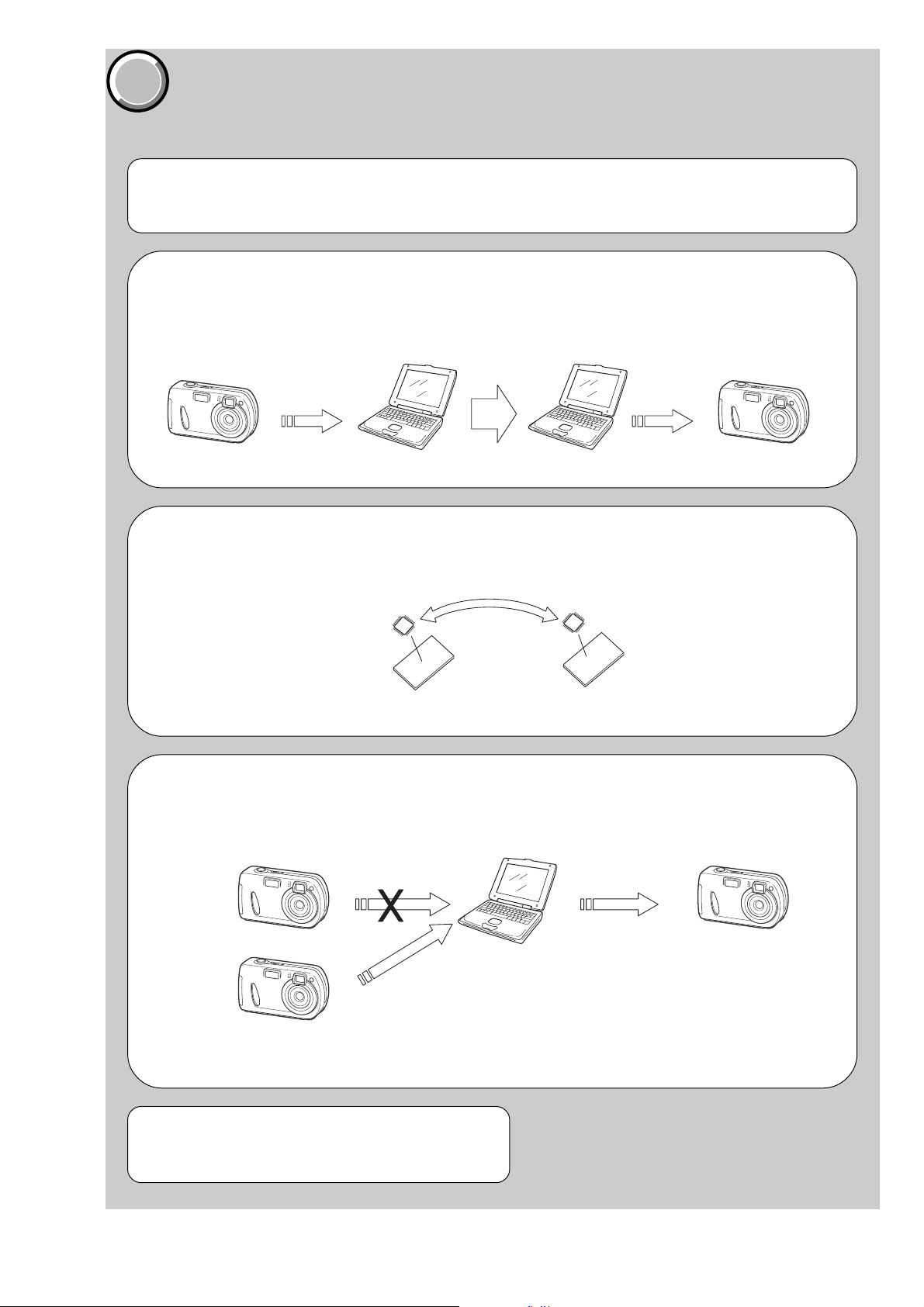
1. Before starting adjustment EVR Data Re-writing Procedure When Replacing Board
The data that is stored in the repair board, is not necessarily correct.
Perform either procedure 1 or procedure 2 or procedure 3 when replacing board.
Procedure 1
Save the EVR data of the machine in which a board is going to be replaced. Download the sa ved data after a board
is replaced.
(Machine before starting repair)
Save the EVR data
to a personal computer.
SECTION 6
ADJUSTMENTS
PC PC
(Machine after a board is replaced)
Download the saved
data to a machine.
Procedure 2
Remove the EEPR OM from the board of the machine that is going to be repaired. Install the removed EEPR OM
to the replaced board.
Remove the EEPROM and install it.
(Former board)
(New board)
Procedure 3
When the data cannot be saved due to defective EEPROM, or when the EEPROM cannot be removed or
installed, save the data from the same model of the same destination, and download it.
(Machine to be repaired) (Machine to be repaired)
PC
Download the data.
Save the data.
(The same model of the same destination)
After the EVR data is saved and downloaded, check the
respective items of the EVR data.
(Refer to page 6-2 for the items to be checked.)
6-1
Page 4
DSC-P32
COVER
COVER
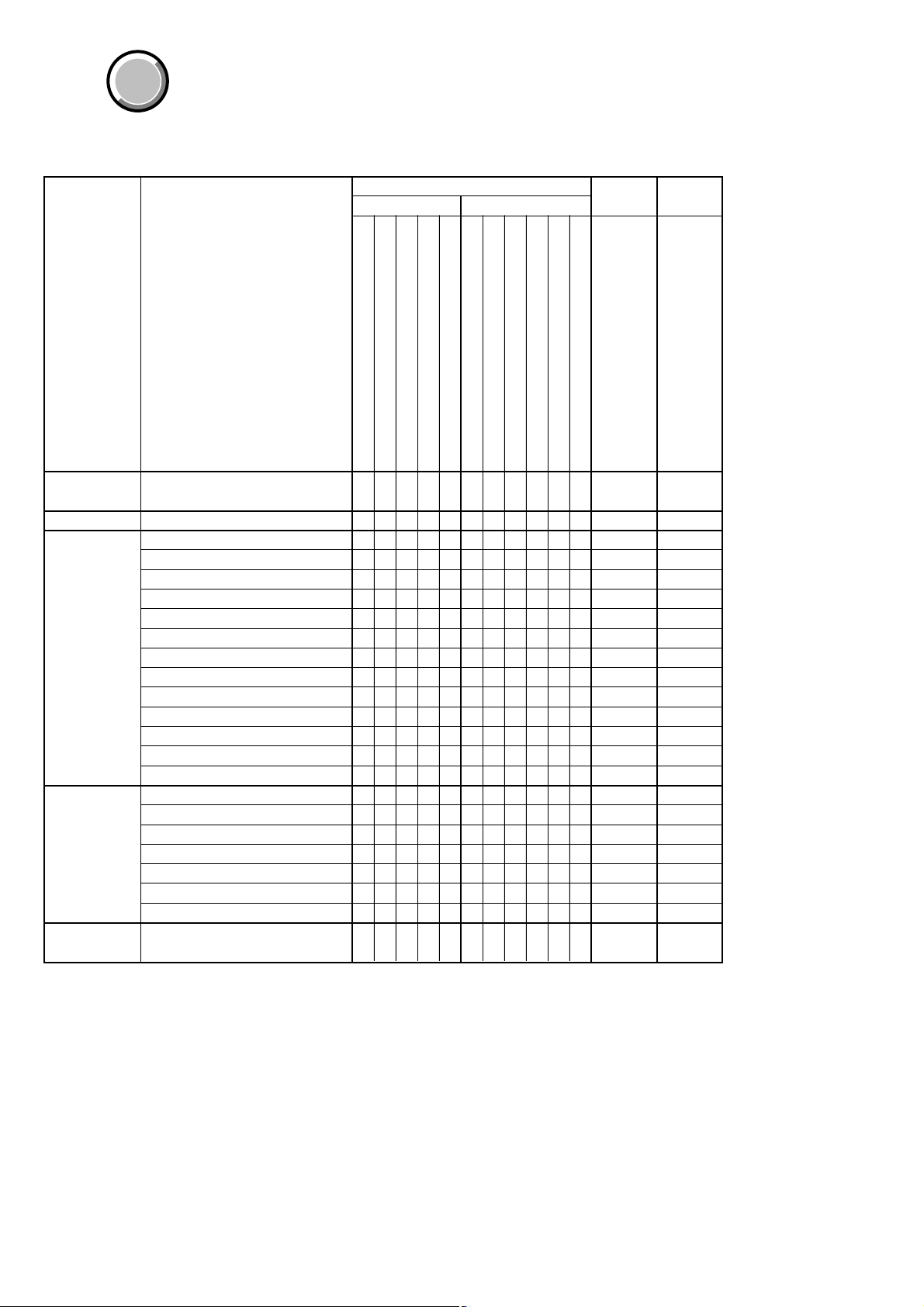
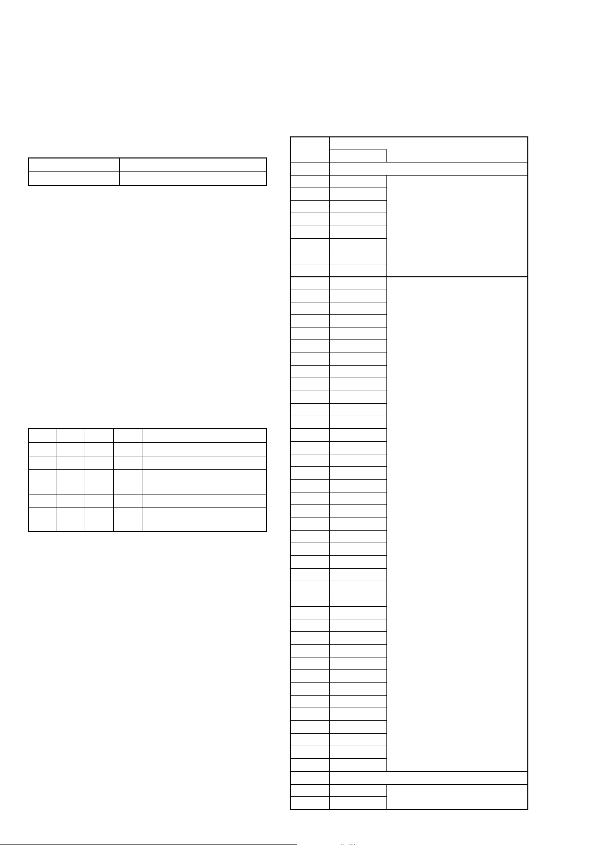
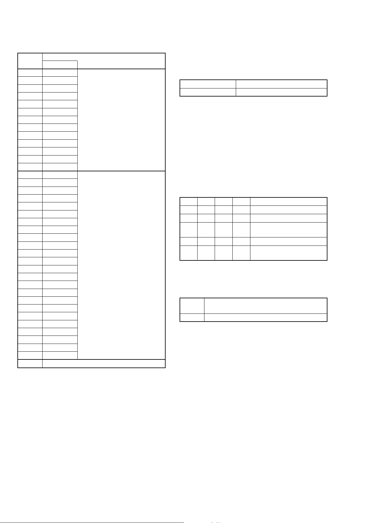
1-1. Adjusting items when replacing main parts and boards.
When replacing main parts, adjust the items indicated by z in the following table.
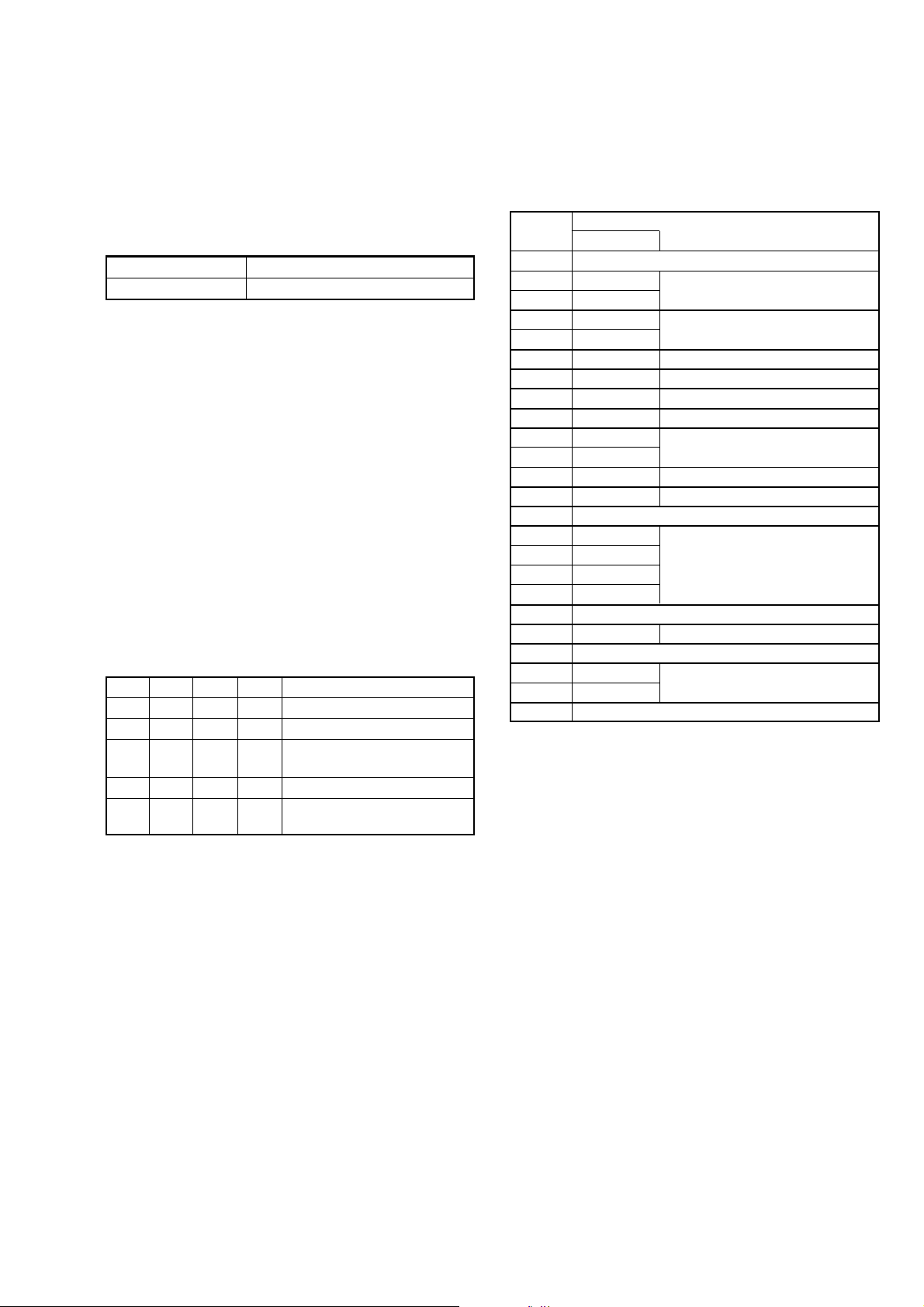
Replaced parts Board EEPROM
Block replacement
Parts replacement
replacement replacement
Adjustment
Section
Initialization of 0E,
2F, 4F, 6F page data
Video
Camera
LCD
System control
Adjustment
Initialization of 0E, 2F, 4F, 6F
page data
Video output level adj.
HALL adj.
Flange back adj.
F No. standard data Input
Mechanical shutter adj.
Light value adj.
AWB 3200K standard data input
AWB 5800K standard data input
CCD linearity check
Color reproduction adj.
CCD white defect compensation check
CCD black defect compensation check
Strobe adj.
Auto focus illumination check
LCD initial data input
VCO adj.
Bright adj.
Contrast adj.
V COM level adj.
V COM adj.
White balance adj.
Battery end adj.
(Timing generator) (LCD)
IC802
Lens device
Flash unit (ST-82)
Parts unit (UA-001)
LCD block LCD unit (LCD901)
LCD block Back light unit
SY-84 board IC351 (CCD imager)
SY-84 board IC901 (S/H, AGC,A/D)
SY-84 board IC301 (CAMERA DSP)
SY-84 board IC601 (Video amp.)
SY-84 board IC801 (RGB drive) (LCD)
SY-84 board
SY-84 board (COMPLETE)
zz
zz z z
zzzzzzzzz
zzzzzzzzz
zzzzzzzzz
zzzzzzzzz
zzzzzzzzz
zzzzzzzzz
zzzzzzzzz
zzzzzzzzz
zzzzzzzzz
zzzzzzzzz
zzzzzzzzz
zz zzzzzz z z
zz zzzzzzz z
zz
zz z z
zz z
zz z z
zz z
zzzz
zz z z z
zz
SY-84 board IC502 (EEPROM)
Table. 6-1-1.
6-2
Page 5
Ver 1.1 2003. 09
COVER
COVER
6-1. ADJUSTMENT
1-1. PREPARATIONS BEFORE ADJUSTMENT
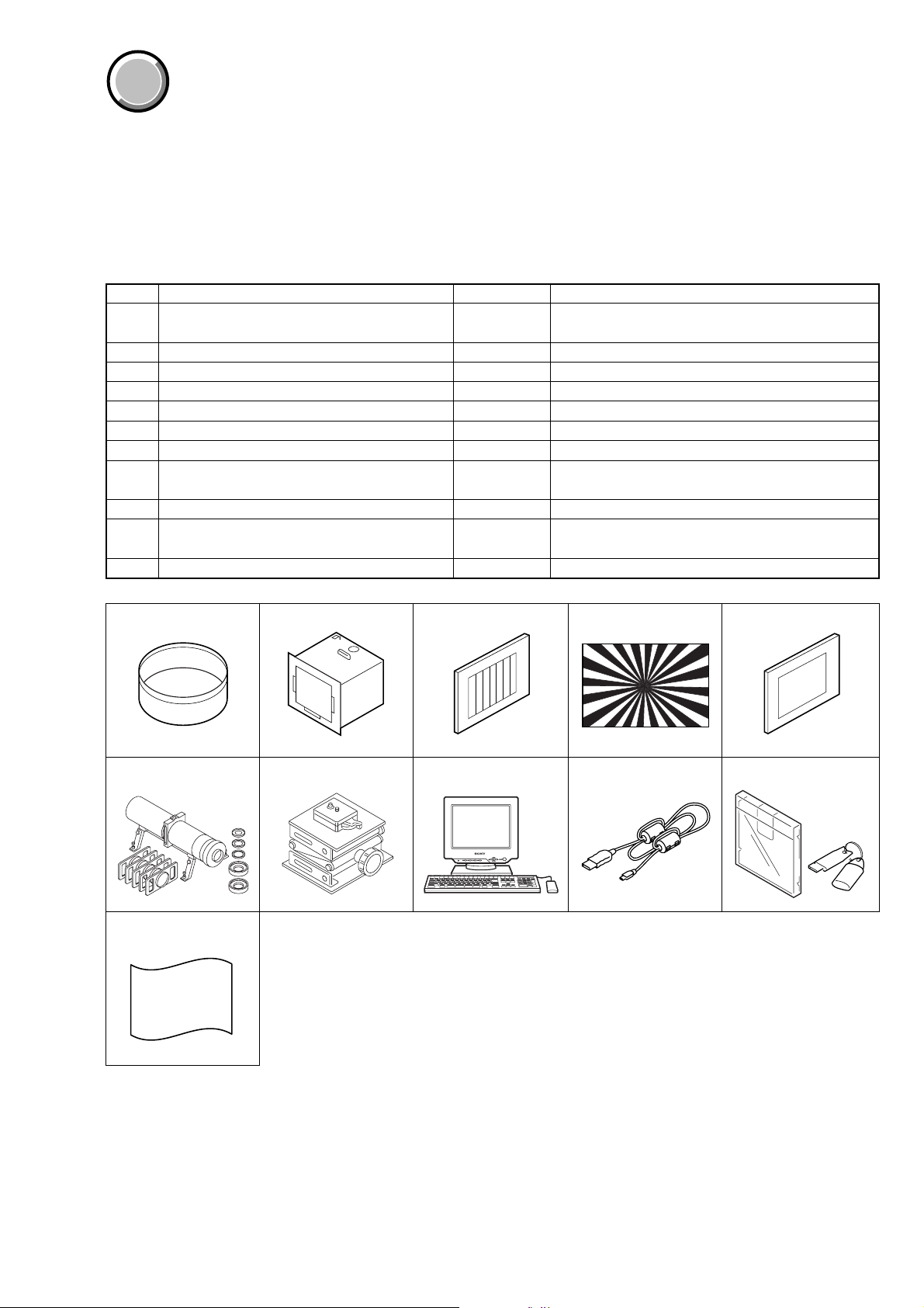
1-1-1. List of Service Tools
• Oscilloscope • Color monitor • Vectorscope • AC power adapter
• Regulated power supply • Digital voltmeter
• Calculator which can hexadecimal calculation.
Ref. No.
J-1
J-2
J-3
J-4
J-5
J-6
J-7
J-8
J-9
J-10
J-11
Filter for color temperature correction (C14)
Pattern box PTB-450
Color chart for pattern box
Siemens star chart
Clear chart for pattern box
Mini pattern box
Camera table
Personal computer with Windows98/ME/2000/XP
installed and with two USB ports
USB cable
Application for adjustment (SEUS) and HASP key
Background paper
Name
Parts Code
J-6080-058-A
J-6082-200-A
J-6020-250-A
J-6080-875-A
J-6080-621-A
J-6082-353-B
J-6082-384-A
1-823-932-11
J-2501-130-A
Usage
Auto white balance adjustment/check
White balance adjustment/check
For checking the flange back
For adjusting the flange back
For adjusting the flange back
For connecting the personal computer
Contact our service headquarter of each area how to get
the application for adjustment (SEUS) and HASP key
For adjusting the strobe
DSC-P32
J-1 J-2 J-3 J-4 J-5
J-6 J-7 J-8 J-9 J-10
J-11
Fig. 6-1-1.
6-3
Page 6
DSC-P32
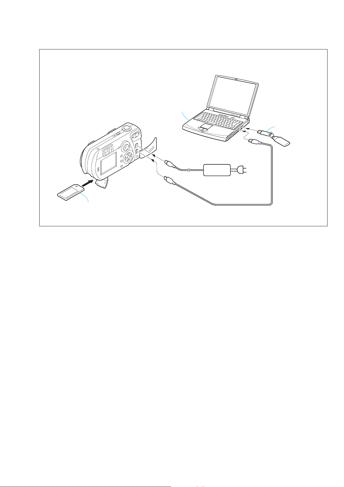
1-1-2. Preparations
1) Connect the equipment for adjustments according to Fig. 6-1-4.
2) Start up the application for adjustment (SEUS).
Note1: Setting the “Forced Power ON Mode (Forced STILL Mode)”
1) Select page: 00, address: 01, and set data: 01.
2) Select page: 2F, address: 21, and write data: 03.
The above procedure will enable the power (STILL mode) to
be turned on with POWER switch (SY-84 board CN705)
disconnected. After completing adjustments, be sure to exit the
“Forced Power ON Mode”.
Note2: Setting the “Forced Power ON Mode (Forced PLAY Mode)”
1) Select page: 00, address: 01, and set data: 01.
2) Select page: 2F, address: 21, and write data: 04.
The above procedure will enable the power (PLAY mode) to be
turned on with POWER switch (SY-84 board CN705)
disconnected. After completing adjustments, be sure to exit the
“Forced Power ON Mode”.
Note3: Exiting the “Forced Power ON Mode”
1) Select page: 00, address: 01, and set data: 01.
2) Select page: 2F, address: 21, and write data: 00.
3) Select page: 00, address: 01, and set data: 00.
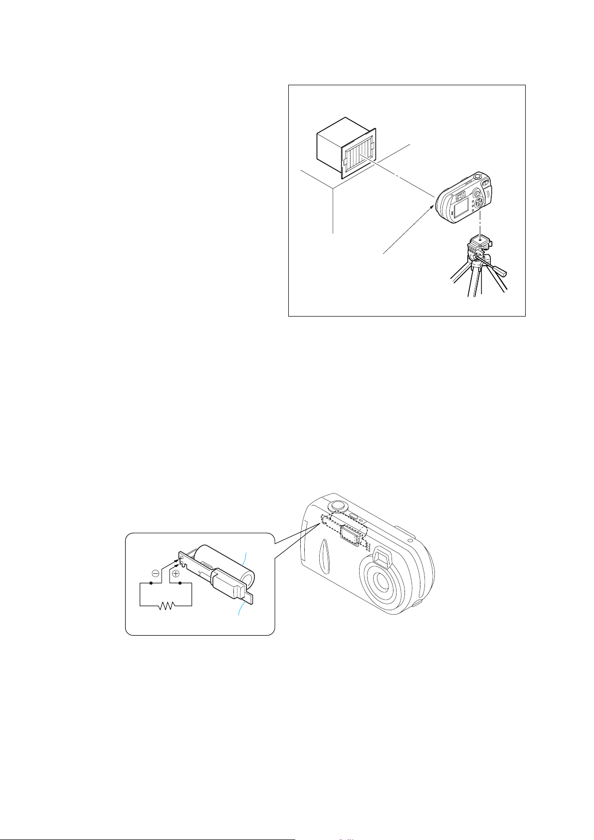
1-1-3. Discharging of the flashlight power supply
The capacitor which is used as power supply of flashlight is charged
with 200V to 300V voltage. Discharge this voltage when opening
the SY-84 board in order to protect service engineers from electric
shock.
Pattern box
About 26cm
Front of the lens
Fig. 6-1-2.
Discharge procedure
1. Remove the power supply (AC power adaptor or battery).
2. Fabricate the discharging jig as shown in Fig. 6-1-3 locally by
yourself. Connect the discharging jig to the positive (+) and
negative (–) terminal of the flash v oltage charge capacitor . Allo w
ten seconds to discharge the voltage.
Capacitor
Shorting jig
(1kΩ / 1w)
ST-82 BOARD
Fig. 6-1-3.
6-4
Page 7
y
[CONNECTION OF EQUIPMENT]
DSC-P32
Personal computer
(with two USB ports)
Memory stick
USB
DC IN
Fig. 6-1-4.
AC power
adaptor
USB1
USB2
AC IN
HASP ke
6-5
Page 8
DSC-P32
e
1-1-4. Precaution
1. Setting the Switch
Unless otherwise specified, set the switches as follows and perform
adjustments.
SETUP settings
USB connect (SETUP2) ........................................NORMAL
MENU settings
Camera ......................................................................... AUTO
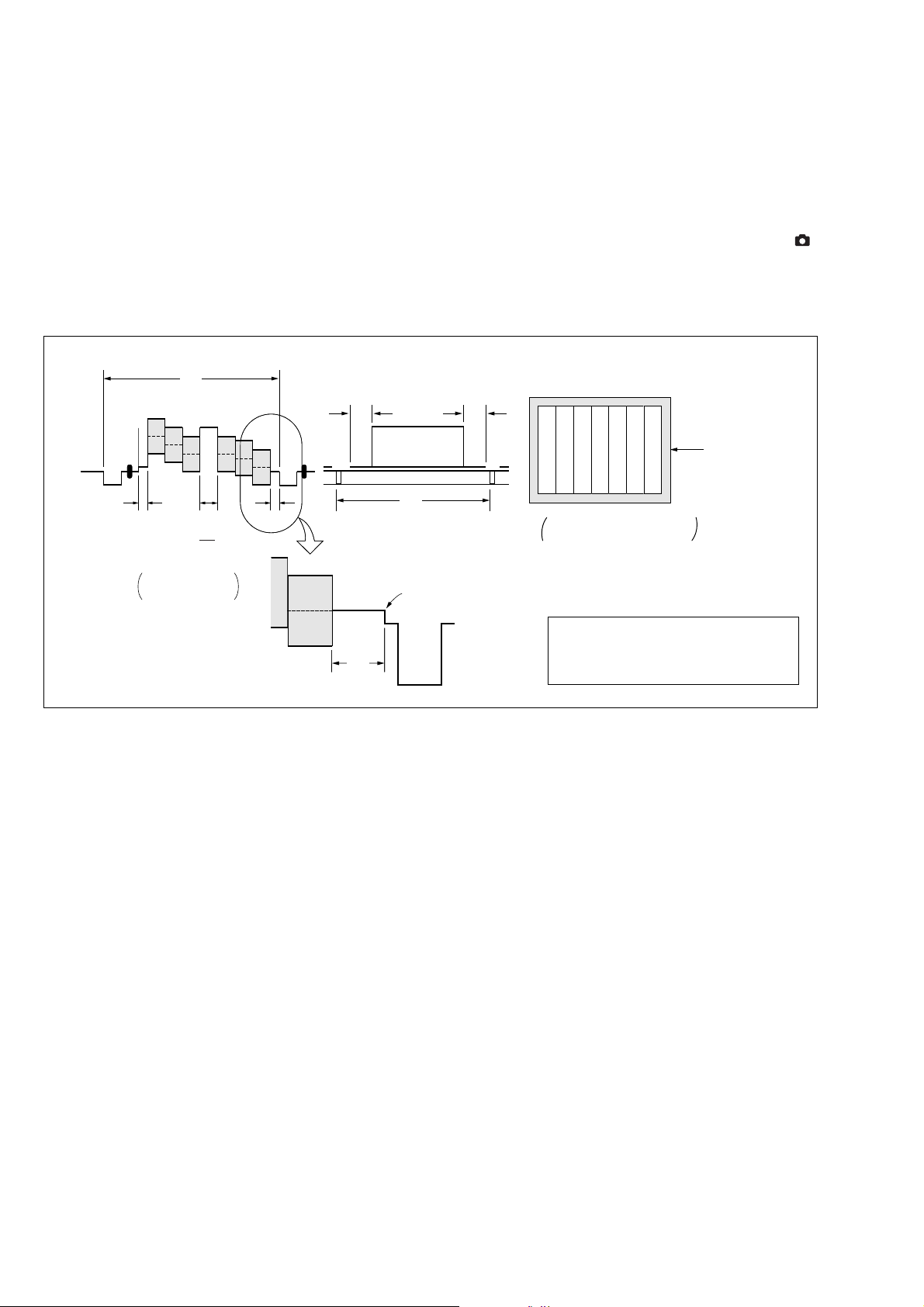
2. Order of Adjustments
Basically carry out adjustments in the order given.
Color bar chart (Color reproduction adjustment frame)
H
Yellow
Cyan
Green
AAB
B
A=
2
Fig. a
Video terminal
output waveform
White
Magenta
Red
Blue
CD
Enlargement
A
Switch settings
1. Mode dial ........................................................... STILL (
2. IMAGE SIZE ................................................................. 3.1M
C=D
Picture fram
V
Difference in level
Cyan
White
Green
Yellow
LCD screen or under scan
Fig. b
monitor TV picture
Adjust the camera position and direction to
obtain the output wavef orm shown in Fig. a
and the LCD screen or the monitor TV
display shown in Fig. b.
Red
Blue
Magenta
)
3. Subjects
1) Color bar chart (Standard picture frame)
When performing adjustments using the color bar chart, adjust
the picture frame as shown in Fig. 6-1-5. (Standard picture
frame)
2) Clear chart (Color reproduction adjustment frame)
Remove the color bar chart from the pattern box and insert a
clear chart in its place. (Do not perform zoom operations during
this time.)
Fig.6-1-5.
6-6
Page 9
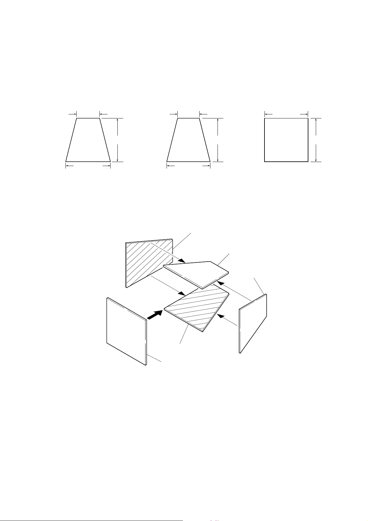
4. Preparing the Flash Adjustment Box
m
A
A dark room is required to provide an accurate strobe adjustment.
If it is not available, prepare the flash adjustment box as giv en below;
1) Provide woody board A, B and C of 15 mm thickness.
DSC-P32
woody board A (2 sheets)
400 mm
513 mm 513 mm 700 m
woody board B (2 sheets)
370 mm
700 mm730 mm
Fig. 6-1-6.
2) Apply black mat paint to one side of woody board A and B.
3) Attach background paper (J-2501-130-A) to woody board C.
4) Assemble so that the black sides and the background paper side
of woody board A, B and C are internal. (Fig. 6-1-7.)
woody board C (1 sheet)
700 mm
woody board A
woody board B
woody board
woody board B
woody board C
Fig. 6-1-7.
6-7
Page 10
DSC-P32
COVER
COVER
1-2. INITIALIZATION OF 0E, 2F, 4F, 6F PAGE
DAT A
1-2-1. INITIALIZATION OF 2F PAGE DATA
1. Initializing the 2F Page Data
Note: If the 2F page data has been initialized, the following adjustments
need to be performed again.
1) Battery end adjustments
Adjusting page 2F
Adjusting Address 00 to 7F
Initializing Method:
1) Select page:00, address:01, and set data:01.
2) Click [Page Edit] on the SEUS screen to display the SEUS
PAGE EDIT screen.
3) Click [Page] to display the INPUT PAGE screen, and input
“2F”.
4) Click [Preset Data Read] on the SEUS PAGE EDIT screen to
display the INPUT SETID screen.
5) Input “04” and click [OK] to read the preset data.
6) On the SEUS P AGE EDIT screen, change the data of the “Fixed
data-2” address shown in the following table by manual input.
Note: New data for changing are not shown in the table because they
are different in destination. When changing the data, copy the
data built in the same model. If copy the data built in the dif ferent
model, the camera may not operate.
7) Check that the data of adjustment addresses is the initial value.
If not, change the data to the initial value.
8) Click [Write] to write the initializing data to the EEPROM of
the camera.
9) Click [Close] to close the SEUS PAGE EDIT screen.
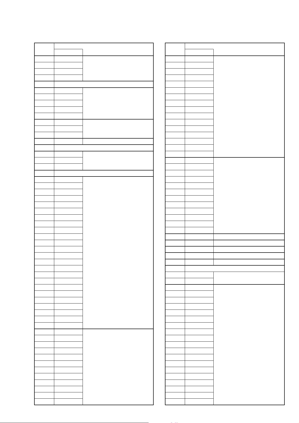
2. 2F Page Table
Note: Fixed data-1: Initialized data. (Refer to “1. Initializing the 2F Page
Data”.)
Fixed data-2: Modified data. (Refer to “2. Modification of 2F Page
Data”.)
Address Remark
Address Remark
00 to 20
22 to 49
4F to 7F
21
4A
4B
4C
4D
4E
Initial value
Initial value
00
4E
57
5F
63
63
Test mode
Fixed data-1
Battery end adj.
Fixed data-1
Table. 6-1-2.
Processing after Completing Initializing of 2F Page data
Order Page
1 20 00 29 Write the data.
2 20 01 29 Write the data.
3 Check “Receive Paket Error” is
4 Turn on the power.
5 Click [Connect] on the SEUS
Address
Data Procedure
displayed on the SEUS screen.
screen.
6-8
Page 11
DSC-P32
1-2-2. Initializing the 4F Page Data
1. Initializing the 4F Page Data
Note: If the 4F page data has been initialized, the following adjustments
need to be performed again.
1) Video system adjustments
2) LCD system adjustments
Adjusting page 4F
Adjusting Address 00 to AF
Initializing Method:
1) Select page:00, address:01, and set data:01.
2) Click [Page Edit] on the SEUS screen to display the SEUS
PAGE EDIT screen.
3) Click [Page] to display the INPUT PAGE screen, and input
“4F”.
4) Click [Preset Data Read] on the SEUS PAGE EDIT screen to
display the INPUT SETID screen.
5) Input “04” and click [OK] to read the preset data.
6) On the SEUS P AGE EDIT screen, change the data of the “Fixed
data-2” address shown in the following table by manual input.
Note: New data for changing are not shown in the table because they
are different in destination. When changing the data, copy the
data built in the same model. If copy the data built in the diff erent
model, the camera may not operate.
7) Check that the data of adjustment addresses is the initial value.
If not, change the data to the initial value.
8) Click [Write] to write the initializing data to the EEPROM of
the camera.
9) Click [Close] to close the SEUS PAGE EDIT screen.
Processing after Completing Initializing of 4F Page data
Order Page
Address
Data Procedure
1 20 00 29 Write the data.
2 20 01 29 Write the data.
3 Check “Receive Paket Error” is
displayed on the SEUS screen.
4 Turn on the power.
5 Click [Connect] on the SEUS
screen.
2. 4F Page Table
Note: Fixed data-1: Initialized data. (Refer to “1. Initializing the 4F
Page Data”.)
Fixed data-2: Modified data. (Refer to “2. Modification of 4F
Page Data”.)
Address Remark
Address Remark
00 to 7E
8C to 91
98 to 9F
A1 to A2
A5 to AF
80
81
82
83
84
85
86
87
88
89
8A
8B
92
93
94
95
A0
A3
A4
Initial value
Initial value
4E
FF
80
90
6D
16
08
87
8D
59
38
00
05
0C
9F
1F
80
24
00
Fixed data-1
Fixed data (LCD)
VCO adj. (LCD)
V COM adj. (LCD)
Bright adj. (LCD)
Fixed data (LCD)
V COM level adj. (LCD)
White balance adj.
Contrast adj. (LCD)
Fixed data (LCD)
Fixed data-1
Fixed data (LCD)
Fixed data-1
Video output level adj.
Fixed data-1
Fixed data (LCD)
Fixed data-1
Table. 6-1-3.
6-9
Page 12
DSC-P32
1-2-3. Initializing the 6F Page Data
1. Initializing the 6F Page Data
Note: If the 6F page data has been initialized, the following adjustments
need to be performed again.
1) Camera system adjustments
Adjusting page 6F
Adjusting Address 00 to FF
Initializing Method:
1) Select page:00, address:01, and set data:01.
2) Click [Page Edit] on the SEUS screen to display the SEUS
PAGE EDIT screen.
3) Click [Page] to display the INPUT PAGE screen, and input
“6F”.
4) Click [Preset Data Read] on the SEUS PAGE EDIT screen to
display the INPUT SETID screen.
5) Input “04” and click [OK] to read the preset data.
6) On the SEUS P AGE EDIT screen, change the data of the “Fixed
data-2” address shown in the following table by manual input.
Note: New data for changing are not shown in the table because they
are different in destination. When changing the data, copy the
data built in the same model. If copy the data built in the dif ferent
model, the camera may not operate.
7) Check that the data of adjustment addresses is the initial value.
If not, change the data to the initial value.
8) Click [Write] to write the initializing data to the EEPROM of
the camera.
9) Click [Close] to close the SEUS PAGE EDIT screen.
Processing after Completing Initializing of 6F Page data
Order Page
Address
Data Procedure
1 20 00 29 Write the data.
2 20 01 29 Write the data.
3 Check “Receive Paket Error” is
displayed on the SEUS screen.
4 Turn on the page.
5 Click [Connect] on the SEUS
screen.
2. 6F Page Table
Note: Fixed data-1: Initialized data. (Refer to “1. Initializing the 6F Page
Data”.)
Fixed data-2: Modified data. (Refer to “2. Modification of 6F Page
Data”.)
Address Remark
Address Remark
00 to 13
3F to 57
10
11
12
13
14
15
16
17
18
19
1A
1B
1C
1D
1E
1F
20
21
22
23
24
25
26
27
28
29
2A
2B
2C
2D
2E
2F
30
31
32
33
34
35
36
37
38
39
3A
3B
3C
3D
3E
58
59
Initial value
Initial value
FF
FF
FF
FF
FF
FF
FF
FF
10
00
10
00
10
1D
00
00
00
00
00
00
20
20
00
02
03
00
00
00
00
00
00
00
00
00
00
00
00
00
00
00
00
00
00
00
00
00
FF
5D
8F
Fixed data-1
Auto focus illumination check
Flange back Adj.
Fixed data-1
HALL adj.
6-10
Page 13
6F page
Address Remark
Address Remark
5E to 5F
69 to 6A
6E to 6F
5A
5B
5C
5D
60
61
62
63
64
65
66
67
68
6B
6C
6D
70
71
72
73
74
75
76
77
78
79
7A
7B
7C
7D
7E
7F
80
81
82
83
84
85
86
87
88
89
8A
8B
8C
8D
8E
8F
90
91
92
93
Initial value
Initial value
13
5B
75
5D
00
00
00
00
00
30
FE
6D
68
FF
00
00
29
83
1F
DF
29
0C
22
6D
00
00
00
00
00
00
00
00
00
00
00
00
00
00
00
00
19
66
30
6E
19
A7
32
FB
00
00
00
00
HALL adj.
Fixed data-1
F No. standard data input
Light value adj.
HALL adj.
Fixed data-1
HALL adj./F No. standard data input/
Mechanical shutter adj.
Fixed data-1
AWB 3200K standard data input
AWB 5200K standard data input
Address Remark
Address Remark
AA
AB
AC
AD
AE
BA
BB
BC
BD
CA
94
95
96
97
98
99
9A
9B
9C
9D
9E
9F
A0
A1
A2
A3
A4
A5
A6
A7
A8
A9
AF
B0
B1
B2
B3
B4
B5
B6
B7
B8
B9
BE
BF
C0
C1
C2
C3
C4
C5
C6
C7
C8
C9
Initial value
Initial value
00
00
00
00
00
00
00
00
00
00
00
00
28
C8
60
00
03
E9
63
83
D5
FE
73
45
28
C8
60
00
00
00
00
00
00
28
6E
10
6B
0F
F6
0F
F7
0F
F2
0F
F7
00
00
00
00
00
30
1B
12
0D
AWB 5200K standard data input
Color reproduction adj.
AWB 3200K standard data input
AWB 5800K standard data input
AWB 3200K standard data input
AWB 5800K standard data input
AWB 3200K standard data input
Fixed data-1
Strobe adj.
Mechanical shutter adj.
DSC-P32
6-11
Page 14
DSC-P32
6F page
Address Remark
Address Remark
CB
CC
CD
CE
CF
D0
D1
D2
D3
D4
D5
D6
D7
D8
D9
DA
DB
DC
DD
DE
DF
EA
EB
EC
ED
EE
F0 to FF
E0
E1
E2
E3
E4
E5
E6
E7
E8
E9
EF
Initial value
Initial value
08
80
88
98
90
88
00
00
00
00
00
00
14
FF
FF
FF
00
00
00
00
00
00
00
00
00
00
00
00
00
00
00
00
00
00
00
00
00
Mechanical shutter adj.
Strobe adj.
Fixed data-1
Table. 6-1-4.
1-2-4. INITIALIZATION OF 0E PAGE DATA
1. Initializing the 0E Page Data
Adjusting page 0E
Adjusting Address 00 to FF
Initializing Method:
1) Select page:00, address:01, and set data:01.
2) Click [Page Edit] on the SEUS screen to display the SEUS
PAGE EDIT screen.
3) Click [Page] to display the INPUT PAGE screen, and input
“0E”.
4) Click [Preset Data Read] on the SEUS PAGE EDIT screen to
display the INPUT SETID screen.
5) Input “00” and click [OK] to read the preset data.
6) Click [Write] to write the initializing data to the EEPROM of
the camera.
7) Click [Close] to close the SEUS PAGE EDIT screen.
Processing after Completing Initializing of 0E Page data
Order Page
1 20 00 29 Write the data.
2 20 01 29 Write the data.
3 Check “Receive Paket Error” is
4 Turn on the power.
5 Click [Connect] on the SEUS
2. 0E Page Table
Note: Fixed data-1: Initialized data. (Refer to “1. Initializing the 0E P age
Data”.)
Address
Address Remark
F0 to FF Fixed data-1
Address
Data Procedure
displayed on the SEUS screen.
screen.
Table. 6-1-5.
6-12
Page 15

COVER
COVER
1-3. VIDEO SYSTEM ADJUSTMENTS
1. Video Output Level Adjustment (SY-84 board)
Adjust the sync level of the composite video signal output.
Mode PLAY ( )
Signal Arbitrary
Measurement Point Video terminal of AV OUT jack
(75 terminated)
Measuring Instrument Oscilloscope
Adjustment Page 4F
Adjustment Address A0
Specified V alue Sync level:
A=286 ± 5mV (NTSC mode)
A=300 ± 5mV (PAL mode)
Burst level:
B=286 ± 30mV (NTSC mode)
B=300 ± 30mV (PAL mode)
SETUP setting:
VIDEO OUT (SETUP 2) ............................ NTSC (NTSC mode)
.................................. PAL (PAL mode)
DSC-P32
Adjusting method:
Order Page
1 00 01 01 Set the data.
2 60 C1 Read the data, and check it is “01”.
3 4F 02 03 Write the data.
4 40 F1 04 Write the data.
5 4F A0 Change the data and set the sync
6 4F A0 Write the data.
7 Check that the burst level (B)
8 4F 02 00 Write the data.
9 40 F1 00 Write the data.
10 00 01 00 Set the data.
Address
Data Procedure
level (A) to the specified value.
satisfies the specified value.
B
A
H
Fig.6-1-8.
6-13
Page 16

DSC-P32
COVER
COVER
1-4. CAMERA SYSTEM ADJUSTMENTS
Before perform the camera system adjustments, check that the
specified values of “VIDEO SYSTEM ADJUSTMENT” are
satisfied.
1. Data Setting during Camera System Adjustments
Perform the following data setting before the camera system
adjustments.
Note1: When the power is turned off, some data settings will be released.
After completing the camera system adjustments, release the data
setting.
So perform this data setting again when the power is turned off.
Order Page
1 00 01 01 Set the data.
2 4F 0F 01 Write the data.
3 4F 02 02 Write the data.
4 2F 21 03 Set the data.
5 60 C1 Read the data, and check it is “02”.
6 60 6C 01 Write the data.
Order Page
1 00 01 01 Set the data.
2 4F 0F 00 Write the data.
3 4F 02 00 Write the data.
4 2F 21 00 Write the data.
5 00 01 00 Set the data.
6 Initialize the 0E page data.
Address
Address
Data Procedure
Data Procedure
(Note2)
2. HALL Adjustment
For detecting the position of the lens iris, adjust the hall AMP g ain
and offset.
Mode STILL ( )
Subject Arbitrary
Measurement Point Data of page 10, address: 07
Measuring Instrument
Adjustment Page 6F
Adjustment Address 58 to 5D, 68, 6B to 6D
Specified Value1 00
Specified Value2 12 to 1A
Specified Value3 7F to 87
Note1: If the data of page: 60, address: 02 is “01”, select page: 60, address:
Adjusting method:
Note2: The adjustment data will be automatically input to page: 6F,
01, and write data: 00.
Order Page
1 Check that “1. Data Setting during
2 00 01 01 Set the data.
3 60 01 6D Write the data.
4 Wait for 1 sec.
5 60 02 Read the data, and check it is “01”.
6 60 01 00 Write the data.
Address
address: 58 to 5D, 68, 6B to 6D.
Data Procedure
Camera System Adjustments” is
performed.
(Note2)
Note2: Refer to “1-2-4. INITIALIZATION OF 0E PAGE DATA”.
Checking method:
Order Page
1 6F 6B Read the data, and check it
2 60 01 01 Write the data.
3 10 07 Read the data, and check it
4 60 01 00 Write the data.
5 60 01 03 Write the data.
6 10 07 Read the data, and check it
Processing after Completing Adjustments:
Order Page
1 60 01 00 Write the data.
2 If finish the camera system
Address
Address
Data Procedure
satisfies the specified value 1.
satisfies the specified value 2.
satisfies the specified value 3.
Data Procedure
adjustments, release the data
setting.
(See “1. Data Setting during
Camera System Adjustments”.)
6-14
Page 17

DSC-P32
3. Flange Back Adjustment
(Using Minipattern Box)
The inner focus lens flange back adjustment is carried out
automatically. In whic he ver case, the focus will be de viated dur ing
auto focusing/manual focusing.
Mode STILL ( )
Subject Siemens star chart with ND filter for
the minipattern box (Note1)
Measurement Point Data of page: 6F, address: 24, 3E
Measuring Instrument
Adjustment Page 6F
Adjustment Address 18 to 3E
Specified value1 00
Specified value2 0A to 40
Note1: Dark siemens star chart.
Note2: If the data of page: 60, address: 02 is “01”, select page: 60, address:
01, and write data: 00.
Preparations:
1) The minipattern box is installed as shown in the following
figure.
Note: The attachment lenses are not used.
2) Install the minipattern box so that the distance between it and
the front of the lens of the camcorder is less than 3cm.
3) Make the height of the minipattern box and the camcorder equal.
4) Check that the output voltage of the regulated po wer supply is
the specified voltage.
5) Check that the center of the siemens star chart and center of
the exposure screen coincide.
Specified voltage:
The specified voltage varies according to the minipattern box, so
adjust the power supply output voltage to the specified voltage
written on the sheet which is supplied with the minipattern box.
Adjusting method:
Order Page
Address
Data Procedure
1 Check that “1. Data Setting
during Camera System
Adjustments” is performed.
2 00 01 01 Set the data.
3 60 01 13 Write the data.
4 60 01 27 Write the data.
5 Wait until the movement of the
lens stops.
6 60 02 Read the data, and check it is “01”.
(Note3)
7 6F 3E Read the data, and check it
satisfies the specified value 1.
8 6F 24 Read the data, and check it
satisfies the specified value 2.
Note3:The adjustment data will be automatically input to page:6F , address:
18 to 3E
Processing after Completing Adjustments:
Order Page
Address
Data Procedure
1 60 01 00 Write the data.
2 Click [Disconnect].
3 Tuen of f the po wer turn on again.
4 Perform “Flange Back Check”.
5 If finish the camera system
adjustments, release the data
setting.
(See “1. Data Setting during
Camera System Adjustments”.)
Minipattern box
Output voltage : Specified voltage ±0.01Vdc
Red (+)
Black (–)
Yellow (SENS +)
White (SENS –)
Black (GND)
Below 3 cm
Camera
Camera
table
Regulated power supply
Output current : more than 3.5A
Need not connected
Fig.6-1-9.
6-15
Page 18

DSC-P32
4. Flange Back Check
Mode STILL ( )
Subject Siemens star
(50cm from the front of the lens)
(Luminance : approx. 300 lux)
Measurement Point Check operation on TV monitor
Measuring Instrument
Specified Value The lens is focused.
Switch setting:
CAMERA setting (Menu setting) ................................ AUTO
Checking method:
Order Page
1 Place the siemens star 50cm from
2 60 90 00 Write the data.
3 60 91 00 Write the data.
4 60 92 00 Write the data.
5 60 93 B0 Write the data.
6 60 01 79 Write the data.
7
8 60 07 Read the data, and check it is “01”.
9 Observe the TV monitor and
10 60 01 00 Write the data.
Address
Data Procedure
the front of the lens.
W ait until the movement of the lens
stops.
check that the lens is focused.
Processing after Completing Adjustments:
Order Page
1 60 01 00 Write the data.
2 60 90 00 Write the data.
3 60 91 00 Write the data.
4 60 92 00 Write the data.
5 60 93 00 Write the data.
Address
Data Procedure
6-16
Page 19

5. Picture Frame Setting
E=F
V
EF
Color bar chart picture frame
Effective picture frame
ABC
Mode STILL ( )
Subject Color bar chart and clear chart
(Standard picture frame)
About 26 cm from the front of the lens
Measurement Point Video terminal of A/V OUT jack
Measuring Instrument Oscilloscope and TV monitor
Specified V alue A=C=B/2, E=F
Switch setting:
CAMERA setting (Menu setting) ................................ AUTO
IMAGE SIZE ................................................................. 3.1M
Setting method:
Order Page
Address
Data Procedure
1 Check that “1. Data Setting during
Camera System Adjustments” is
performed.
2 Shoot the color bar chart.
3 Adjust the direction and distance
between the pattern box and
camera, and set the picture
frame to the specified position.
4 Remove the color bar chart and set
the clear chart.
5 Check that the whole of the
screen is white. If not, adjust the
direction and distance slightly.
6 10 44 Read the data, and this data named
YH.
7 10 45 Read the data, and this data named
YL.
8 60 2C 01 Write the data.
9
Perform the following adjustments.
Check on an oscilloscope
1. Horizontal period
A = C =
A
Fig. 6-1-10.
2. V ertical period
DSC-P32
B
2
B
C
How to reset the focus when they deviated:
If the zoom and focus deviated due to some reason reset them in the
following method.
Order Page
Address
Data Procedure
1 60 2C 01 Write the data.
2 60 90 00 Write the data.
3 60 91 00 Write the data.
4 60 92 YL Write the data. Note
5 60 93 YH Write the data. Note
6 60 01 79 Write the data.
7 Wait until the movement of the
8 60 07 Read the data, and check it is “01”.
9 60 01 00 Write the data.
Note: YH and YL are the data read in the “Setting method”.
Fig. 6-1-11.
Check on the monitor TV (Underscanned mode)
lens stops.
Fig. 6-1-12.
6-17
Page 20

DSC-P32
6. F No. Standard Data Input
Adjusted the dispersion of the iris to every to every F number, and
compensate the exposure.
Mode STILL ( )
Subject Clear chart
(Standard picture frame)
Measurement Point Data of page: 6F, address: 6B
Measuring Instrument
Adjustment Page 6F
Adjustment Address 60 to 64, 6B to 6D
Specified value 00
Note1: If the data of page: 60, address: 02 is “01”, select page: 60, address:
01, and write data: 00.
Switch setting:
CAMERA setting (Menu setting) ................................ AUTO
Adjusting method:
Order Page
Address
Data Procedure
1 Check that “1. Data Setting
during Camera System
Adjustments” is performed.
2 Check the picture frame.
If deviated, perform “5. Picture
Frame Setting”.
3 00 01 01 Set the data.
4 60 01 BB Write the data.
5 Wait for 1 sec.
6 60 02 Red the data, and check it is “01”.
(Note2)
7 6F 6B Read the data, and check it
satisfies the specified v alue.
Note2: The adjustment data will be automatically input to page: 6F,
address: 60 to 64, 6B to 6D.
Processing after Completing Adjustments:
Order Page
Address
Data Procedure
1 60 01 00 Write the data.
2 If finish the camera system
adjustments, release the data
setting.
(See “1. Data Setting during
Camera System Adjustments”.)
7. Mechanical Shutter Adjustment
Adjust the dispersion of the opening/closing time and the closing
loss rate of the mechanical shutter. and compensate the exposure.
Mode STILL ( )
Subject Clear chart
(Standard picture frame)
Measurement Point Data of page: 6F, address: 6B
Measuring Instrument
Adjustment Page 6F
Adjustment Address 6B to 6D, B8 to D7
Specified value 00
Note1: If the data of page: 60, address: 02 is “01”, select page: 60, address:
01, and write data: 00.
Switch setting:
CAMERA setting (Menu setting) ................................ AUTO
Adjusting method:
Order Page
Address
Data Procedure
1 Check that “1. Data Setting
during Camera System
Adjustments” is performed.
2 Check the picture frame.
If deviated, perform “5. Picture
Frame Setting”.
3 00 01 01 Set the data.
4 60 01 AD Write the data.
5 Wait until the movement of the
shutter stops.
6 60 02 Read the data, and check it is “01”.
(Note2)
7 6F 6B Read the data, and check it
satisfies the specified value.
Note2: The adjustment data will be automatically input to page: 6F,
address: 6B to 6D, B8 to D7.
Processing after Completing Adjustments:
Order Page
Address
Data Procedure
1 60 01 00 Write the data.
2 If finish the camera system
adjustments, release the data
setting.
(See “1. Data Setting during
Camera System Adjustments”.)
6-18
Page 21

8. Light Value Adjustment
Adjust the standard LV value.
Mode STILL ( )
Subject Clear chart
(Standard picture frame)
Measurement Point Data of page: 10, address: 0C, 0D
Measuring Instrument Data of page: 6F, address: 65
Adjustment Page 6F
Adjustment Address 65 to 67
Specified value1 0FE0 to 1020
Specified value2 2D to 58
DSC-P32
Note1: If the data of page: 60, address: 02 is “01”, select page: 60, address:
Switch setting:
Adjusting method:
01, and write data: 00.
CAMERA setting (Menu setting) ................................ AUTO
Order Page
1 Check that “1. Data Setting
2 Check the picture frame.
3 00 01 01 Set the data.
4 60 01 0D Write the data.
5 Wait for 1 sec.
6 60 02 Read the data, and check it is “01”.
7 10 0C Read the data, and this data is
8 10 0D Read the data, and this data is
9 Calculate DLV using the
10 Check that DLV satisfies the
11 6F 65 Read the data, and check it
Address
Data Procedure
during Camera System
Adjustments” is performed.
If deviated, perform “5. Picture
Frame Setting”.
(Note2)
named D0C.
named D0D.
following equation.
(Hexadecimal calculation.)
DLV = D0C × 100 + D0D
specified value1.
satisfies the specified value2.
Note2: The adjustment data will be automatically input to page: 6F,
Processing after Completing Adjustments:
address: 65 to 67.
Order Page
1 60 01 00 Write the data.
2 If finish the camera system
Address
Data Procedure
adjustments, release the data
setting.
(See “1. Data Setting during
Camera System Adjustments”.)
6-19
Page 22

DSC-P32
9. Auto White Balance 3200K Standard Data Input
Adjust the white balance standard data at 3200K.
Mode STILL ( )
Subject Clear chart
(Standard picture frame)
Measurement Point Data of page: 6F, address: B5
Measuring Instrument
Adjustment Page 6F
Adjustment Address 70 to 87, B0, B2, B4
Specified value 00
Note1: If the data of page: 60, address: 02 is “01”, select page: 60, address:
Switch setting:
Adjusting method:
Note2: The adjustment data will be automatically input to page: 6F,
01, and write data: 00.
ZOOM.................................................................... WIDE end
CAMERA setting (Menu setting) ................................ AUTO
Order Page
1 Install the Clear chart.
2 Check that “1. Data Setting during
3
4 00 01 01 Set the data.
5 6F B5 FF Write the data.
6 60 02 Read the data, and check it is “00”.
7 60 37 01 Write the data.
8 60 01 11 Write the data.
9 60 38 Read the data, and check it is “01”.
10 60 01 C1 Write the data.
11 Wait for 1 sec.
12 60 02 Read the data, and check it is “01”.
13 60 01 00 Write the data.
14 60 02 Read the data, and check it is “00”.
15 60 37 02 Write the data.
16 60 01 0B Write the data.
17 Wait for 3 sec.
18 60 02 Read the data, and check it is “01”.
19 60 01 00 Write the data.
20 6F B5
Address
address: 70 to 87, B0, B2, B4.
Data Procedure
Camera System Adjustments” is
performed.
Check the picture frame. If deviated,
perform “4. Picture Frame Setting”.
3200K standard data input (1)
(Note2)
3200K standard data input (2)
(Note2)
Read the data, and check it
satisfies the specified value.
Processing after Completing Adjustments:
Order Page
1 60 37 00 Write the data.
2 60 01 00 Write the data.
3 Perform next adjustments.
Address
Data Procedure
If finish the camera system
adjustments, release the data
setting.
(See “1. Data Setting during
Camera System Adjustments”.)
6-20
Page 23

DSC-P32
10.Auto White Balance 3200K Check
Check that the white balance standard data at 3200K are inputted
properly.
Mode STILL ( )
Subject Clear chart
(Standard picture frame)
Measurement Point Data of page: 10, address: 08, 09, 0A,
0B, 59, 5B
Measuring Instrument Data of page: 6F, address: 74, 76, B5
Specified value 1 R ratio = 3F00 to 4100
Specified value 2 B ratio = 3F00 to 4100
Specified value 3 R-Y data = 7A to 86
Specified value 4 B-Y data = 7A to 86
Specified value 5 R/G data = 20 to 60
Specified value 6 B/G data = 10 to 40
Specified value 7 00
Note: If the data of page: 60, address: 02 is “01”, select page: 60, address:
01, and write data: 00.
Switch setting:
ZOOM.................................................................... WIDE end
CAMERA setting (Menu setting) ................................ AUTO
Adjusting method:
Order Page
1 Check that “1. Data Setting during
2 Check the picture frame.
3 00 01 01 Set the data.
4 6F B5 FF Write the data.
5 60 37 0D Write the data.
6 60 01 11 Write the data.
7 Wait for 1 sec.
8 60 38 Read the data, and check it is “01”.
9 60 01 C1 Write the data.
10 Wait for 1 sec.
11 60 02 Read the data, and check it is “01”.
12 10 08 Read the data, and this data is
13 10 09 Read the data, and this data is
14 Calculate R ratio using the
15 Check that R ratio satisfies the
16 10 0A Read the data, and this data is
17 10 0B Read the data, and this data is
Address
Data Procedure
Camera System Adjustments” is
performed.
If deviated, perform “4. Picture
Frame Setting”.
3200K standard data Check (1)
named D08.
named D09.
following equation
(Hexadecimal calculation)
R ratio = D08 × 100 + D09
specified value1.
named D0A.
named D0B.
Order Page
18 Calculate B ratio using the
19 Check that B ratio satisfies the
20 10 59
21 10 5B
22 60 01 00 Write the data.
23 6F 74
24 6F 76
25 6F B5 Read the data, and check it
Processing after Completing Adjustments:
Order Page
1 60 37 00 Write the data.
2 60 01 00 Write the data.
3 Perform next adjustments.
Address
Address
Data Procedure
following equation
(Hexadecimal calculation)
B ratio = D0A × 100 + D0B
specified value2.
Read the data (R-Y data), and check
it satisfies the specified value3.
Read the data (B-Y data), and check
it satisfies the specified value4.
3200K standard data Check (2)
Read the data (R/G data), and check
it satisfies the specified value 5.
Read the data (B/G data), and check
it satisfies the specified value 6.
satisfies the specified value 7.
Data Procedure
If finish the camera system
adjustments, release the data
setting.
(See “1. Data Setting during
Camera System Adjustments”.)
6-21
Page 24

DSC-P32
11.Auto White Balance 5800K Standard Data Input
Adjust the white balance standard data at 5800K.
Mode STILL ( )
Subject Clear chart
(Standard picture frame)
Filter Filter C14 for color temperature
correction
Measurement Point Data of page: 6F, address: B5
Measuring Instrument
Adjustment Page 6F
Adjustment Address 88 to A3, B1, B3
Specified value 00
Note1: If the data of page: 60, address: 02 is “01”, select page: 60, address:
Switch setting:
Adjusting method:
01, and write data: 00.
CAMERA setting (Menu setting) ................................ AUTO
Order Page
1 Place the C14 filter for color
2 Check that “1. Data Setting
3 Check the picture frame.
4 00 01 01 Set the data.
5 6F B5 FF Write the data.
6 6F A0 Read the data, this data is named
7 6F A0 28 Write the data.
8 6F A1 Read the data, this data is named
9 6F A1 C8 Write the data.
10 6F A2 Read the data, this data is named
11 6F A2 60 Write the data.
12 6F A3 Read the data, this data is named
13 6F A3 00 Write the data.
14 60 37 07 Write the data.
15 60 01 11 Write the data.
16 60 38 Read the data, and check it is “01”.
17 60 01 C3 Write the data.
18 Wait for 1 sec.
19 60 02 Read the data, and check it is “01”.
20 60 01 00 Write the data.
21 60 37 08 Write the data.
22 60 01 A5 Write the data.
23 Wait for 2 sec.
Address
Data Procedure
temperature correction on the lens.
during Camera System
Adjustments” is performed.
If deviated, perform “5. Picture
Frame Setting”.
DA0, and memorize it.
DA1, and memorize it.
DA2, and memorize it.
DA3, and memorize it.
5800K standard data input (1).
(Note2)
5800K standard data input (2).
Order Page
24 60 02 Read the data, and check it is “01”.
25 60 01 00 Write the data.
26 6F B5 Read the data, and check it
Note2: The adjustment data will be automatically input to page: 6F,
Processing after Completing Adjustments:
Order Page
1 60 37 00 Write the data.
2 60 01 00 Write the data.
3 Perform next adjustments.
Address
address: 88 to A3, B1, B3.
Address
Data Procedure
Data Procedure
(Note2)
satisfies the specified value.
If finish the camera system
adjustments, perform
“Processing after Completing
Adjustments” of “12. Auto
White Balance 5800K Check”.
6-22
Page 25

DSC-P32
12.Auto White Balance 5800K Check
Check that the white balance standard data at 5800K are inputted
properly.
Mode STILL ( )
Subject Clear chart
(Standard picture frame)
Filter Filter C14 for color temperature
correction
Measurement Point Data of page: 10, address: 08, 09, 0A,
0B, 59, 5B
Measuring Instrument Data of page: 6F, address: 8C, 8E, B5
Specified value 1 R ratio = 2838 to 2C38
Specified value 2 B ratio = 5DA0 to 61A0
Specified value 3 R-Y data = 70 to 90
Specified value 4 B-Y data = 70 to 90
Specified value 5 R/G data = 10 to 40
Specified value 6 B/G data = 10 to 40
Specified value 7 00
Note1: Before perform this adjustment, perform “Auto White Balance
Note2: If the data of page: 60, address: 02 is “01”, select page: 60, address:
5800K Standard Data Input”.
01, and write data: 00.
Switch setting:
ZOOM.................................................................... WIDE end
CAMERA setting (Menu setting) ................................ AUTO
Adjusting method:
Order Page
Address
Data Procedure
1 Place the C14 filter for color
temperature correction on the
lens.
2 Check that “1. Data Setting during
Camera System Adjustments” is
performed.
3 Check the picture frame.
If deviated, perform “4. Picture
Frame Setting”.
4 00 01 01 Set the data.
5 6F B5 FF Write the data.
5800K standard data Check (1).
6 60 37 13 Write the data.
7 60 01 11 Write the data.
8 60 38 Read the data, and check it is “01”.
9 60 01 C3 Write the data.
10 Wait for 2 sec.
11 60 02 Read the data, and check it is “01”.
12 10 08 Read the data, and this data is
named D08.
13 10 09 Read the data, and this data is
named D09.
14 Calculate R ratio using the
following equation.
(Hexadecimal calculation.)
R ratio = D08 × 100 + D09
15 Check that R ratio satisfies the
specified value1.
16 10 0A Read the data, and this data is
named D0A.
Order Page
Address
Data Procedure
17 10 0B Read the data, and this data is
named D
0B.
18 Calculate B ratio using the
following equation.
(Hexadecimal calculation.)
B ratio = D0A × 100 + D0B
19 Check that B ratio satisfies the
specified value 2.
20 10 59 Read the data (R-Y data), and
check it satisfies the specified
value 3.
21 10 5B Read the data (B-Y data), and
check it satisfies the specified
value 4.
22 60 01 00 Write the data.
5800K standard data Chec k (2).
23 6F 8C Read the data (R/G data), and
check it satisfies the specified
value 5.
24 6F 8E Read the data (B/G data), and
check it satisfies the specified
value 6.
25 6F B5 Read the data, and check it
satisfies the specified value 7.
Processing after Completing Adjustments:
Order Page
Address
Data Procedure
1 60 37 00 Write the data.
2 60 01 00 Write the data.
3 Perform next adjustments.
If finish the camera system
adjustments, release the data
setting.
(See “1. Data Setting during
Camera System Adjustments”.)
6-23
Page 26

DSC-P32
13.CCD Linearity Check
Data picking is done to keep output linearity of the CCD imager,
even if the input level of CCD imager changes.
Mode STILL ( )
Subject Clear chart (Standard picture frame)
Specified value1 97 to 103
Specified value2 97 to 103
Note: If the data of page: 60, address: 02 is “01”, select page: 60, address:
01, and write data: 00.
Switch setting:
CAMERA setting (Menu setting) ................................ AUTO
Adjusting method:
Order Page
1 Check that “1. Data Setting
2 Check the picture frame. If
3 00 01 01 Set the data.
4 75 09 Read the data, and memorize it.
5 75 09 04 Write the data.
6 60 1F 80 Write the data.
7 77 F7 Read the data, and memorize it.
8 77 F7 42 Write the data.
9 77 F2 Read the data, and memorize it.
10 77 F2 02 Write the data.
11 60 14 90 Write the data.
12 60 12 9F Write the data.
13 Wait for 2 sec.
14 60 01 F9 Write the data.
15 Wait for 2 sec.
16 60 E1
17 10 80 Read the data, and this data is
18 10 81 Read the data, and this data is
19 Calculate DRG using the
20 10 82 Read the data, and this data is
21 10 83 Read the data, and this data is
22 Calculate DBG using the
23 60 01 00 Write the data.
24 60 E1 00 Write the data.
25 77 72 Read the data, and memorize it.
26 77 72 32 Write the data.
27 Wait for 2 sec.
28 60 01 F9 Write the data.
Address
Data Procedure
during Camera System
Adjustments” is performed.
deviated, perform “5. Picture
Frame Setting”.
Read the data, and check it is “08”.
named D80.
named D81.
following equation
(Hexadecimal calculation)
DRG0 = D80 ×100 + D81
named D82.
named D83.
following equation
(Hexadecimal calculation)
DBG0 = D82 × 100 + D83
Order Page
29 Wait for 2 sec.
30 60 E1
31 10 80 Read the data, and this data is
32 10 81 Read the data, and this data is
33 Calculate DRG using the
34 10 82 Read the data, and this data is
35 10 83 Read the data, and this data is
36 Calculate DBG using the
37 60 01 00 Write the data.
38 60 E1 00 Write the data.
39 77 72 0A Write the data.
40 Wait for 2 sec.
41 60 01 F9 Write the data.
42 Wait for 2 sec.
43 60 E1
44 10 80 Read the data, and this data is
45 10 81 Read the data, and this data is
46 Calculate DRG using the
47 10 82 Read the data, and this data is
48 10 83 Read the data, and this data is
49 Calculate DBG using the
50 60 01 00 Write the data.
51 60 E1 00 Write the data.
52 Convert DRG0, DBG0, DRGH,
53 Calculate R/G ratio (H), B/G
Address
Data Procedure
Read the data, and check it is “08”.
named D
named D81.
following equation
(Hexadecimal calculation)
DRGH = D80 × 100 + D81
named D82.
named D83.
following equation
(Hexadecimal calculation)
DBGH = D82 × 100 + D83
Read the data, and check it is “08”.
named D80.
named D81.
following equation
(Hexadecimal calculation)
DRGL = D80 × 100 + D81
named D82.
named D83.
following equation
(Hexadecimal calculation)
DBGL = D82 × 100 + D83
DBGH, DRGL and DBGL to decimal
number, and obtain DRG0’, DBG0’,
DRGH’, DBGH’, DRGL’ and DBGL’.
ratio (H), R/G ratio (L) and B/G
ratio (L), using the following
equations (Decimal calculation)
80.
R/G ratio (H) =
(DRGH’ / DRG0’) ×100
B/G ratio (H) =
(DBGH’ / DBG0’) × 100
R/G ratio (L) =
(DRGL’ / DRG0’) × 100
B/G ratio (L) =
(DBGL’ / DBG0’) ×100
6-24
Page 27

DSC-P32
Order Page
54 Check that R/G ratio (H)
55 Check that B/G ratio (H)
56 Check that R/G ratio (L)
57 Check that B/G ratio (L)
Processing after Completing Adjustments:
Order Page
1 60 12 00 Write the data.
2 60 14 00 Write the data.
3 60 1F 00 Write the data.
4 75 09 Write the data memorized at
5 77 F7 Write the data memorized at
6 77 F2 Write the data memorized at
7 77 72 Write the data memorized at
8 Perform next adjustments.
Address
Address
Data Procedure
satisfies the specified value 1.
(Decimal number)
satisfies the specified value 1.
(Decimal number)
satisfies the specified value 2.
(Decimal number)
satisfies the specified value 2.
(Decimal number)
Data Procedure
step 4.
step 7.
step 9.
step 25.
If finish the camera system
adjustments, release the data
setting.
(See “1. Data Setting during
Camera System Adjustments”.)
14.Color Reproduction Adjustment
Adjust the color Separation matrix coefficient so that proper color
reproduction is produced.
Mode STILL ( )
Subject Color bar chart
(Standard picture frame)
Measurement Point Data of page: 6F, address: B5
Measuring Instrument
Adjustment Page 6F
Adjustment Address A4 to AF
Specified value 00
Note1: If the data of page: 60, address: 02 is “01”, select page: 60, address:
Switch setting:
Adjusting method:
01, and write data: 00.
ZOOM.................................................................... WIDE end
CAMERA setting (Menu setting) ................................ AUTO
VIDEO OUT (SET UP setting) ....................................NTSC
Order Page
1 Install the color bar chart.
2 Check that “1. Data Setting during
3 Check the picture frame.
4 00 01 01 Set the data.
5 6F B5 FF Write the data.
6 60 01 AB Write the data.
7 60 12 80 Write the data.
8 Wait for 1 sec.
9 60 12 00 Write the data.
10 Wait for 2 sec.
11 60 01 A9 Write the data.
12 Wait until the color of the screen
13 60 02 Read the data, and check it is “01”.
14 6F B5 Read the data, and check it
Address
Data Procedure
Camera System Adjustments” is
performed.
If deviated, perform “4. Picture
Frame Setting”.
stops changing.
(Note2)
satisfies the specified v alue.
Note2: The adjustment data will be automatically input to page: 6F,
Processing after Completing Adjustments:
address: A4 to AF.
Order Page
1 60 01 00 Write the data.
2 Perform next adjustments.
Address
Data Procedure
If finish the camera system
adjustments, release the data
setting.
(See “1. Data Setting during
Camera System Adjustments”.)
6-25
Page 28

DSC-P32
Burst position
White
15.Color Reproduction Check
Check that the color reproduction adjustment is done properly.
Mode STILL ( )
Subject Color bar chart
(Standard picture frame)
Measurement Point Video terminal of A/V OUT jack
Measuring Instrument NTSC vectorscope
Specified Value Each center of all color luminance
points should settle within each color
reproduction frame.
Note: If the data of page: 60, address: 02 is “01”, select page: 60, address:
01, and write data: 00.
Switch setting:
ZOOM.................................................................... WIDE end
CAMERA setting (Menu setting) ................................ AUTO
VIDEO OUT (SET UP setting) ....................................NTSC
Checking method:
Order Page
1 Check that “1. Data Setting during
2 Check the picture frame.
3 00 01 01 Set the data.
4 60 01 AB Write the data.
5 60 12 80 Write the data.
6 Wait for 1 sec.
7 60 12 00 Write the data.
8 Wait for 2 sec.
9 Adjust the GAIN and PHASE of
10 Check that each center of all color
Address
Data Procedure
Camera System Adjustments” is
performed.
If deviated, perform “4. Picture
Frame Setting”.
the vectorscope so that the burst
luminance point is set at the
specified position.
luminance points is set in each
color reproduction frame.
Fig. 6-1-13.
Processing after Completing Adjustments:
Order Page
1 60 01 00 Write the data.
2 Perform next adjustments.
Address
Data Procedure
If finish the camera system
adjustments, release the data
setting.
(See “1. Data Setting during
Camera System Adjustments”.)
6-26
Page 29

16.CCD White Defect Compensation Check
The positions of the white defective pixel are detected, and check
that the pixels can be corrected.
Mode STILL ( )
Subject Clear chart
(Standard picture frame)
Measurement Point Data of page: 60, address: 55
Measuring Instrument
Specified value 1 00 to 7F
Specified value 2 00
Note: If the data of page: 60, address: 02 is “01”, select page: 60, address:
01, and write data: 00.
Switch setting:
CAMERA setting (Menu setting) ................................ AUTO
Adjusting method:
Order Page
1 Install the clear chart.
2 Check that “1. Data Setting during
3 Check the picture frame.
4 00 01 01 Set the data.
5 7D 64 1E Write the data.
6 7D 69 11 Write the data.
7 60 01 8B Write the data.
8 Wait for 10 sec.
9 60 02 Read the data, and check it is “01”.
10 60 55 Read the data, and check it
11 60 01 00 Write the data.
12 7D 64 0F Write the data.
13 7D 69 60 Write the data.
14 60 01 87 Write the data.
15 Wait for 5 sec.
16 60 02 Read the data, and check it is “01”.
17 60 55 Read the data, and check it
Address
Data Procedure
Camera System Adjustments” is
performed.
If deviated, perform “5. Picture
Frame Setting”.
satisfies the specified value 1.
satisfies the specified value 2.
DSC-P32
Processing after Completing Adjustments:
Order Page
1 60 01 00 Write the data.
2 7D 64 0F Write the data.
3 7D 69 30 Write the data.
4 Perform next adjustments.
Address
Data Procedure
If finish the camera system
adjustments, release the data
setting.
(See “1. Data Setting during
Camera System Adjustments”.)
6-27
Page 30

DSC-P32
17.CCD Black Defect Compensation Check
The positions of the black defective pixel are detected, and check
that the pixels can be corrected. And conf irms that there is no trash
in the surface of the CCD imager, the optical f ilter and the inside of
the lens.
Mode STILL ( )
Subject Clear chart
(Standard picture frame)
Measurement Point Data of page: 60, address: 55
Measuring Instrument
Specified value 1 00 to 0A
Specified value 2 00
Note1: Check that there are no dust, no dirt and no reflection on the clear
Note2: If the data of page: 60, address: 02 is “01”, select page: 60, address:
Switch setting:
Adjusting method:
chart.
01, and write data: 00.
CAMERA setting (Menu setting) ................................ AUTO
Order Page
1 Check that “1. Data Setting during
2 Check the picture frame.
3 00 01 01 Set the data.
4 7D 65 4C Write the data.
5 60 2C 01 Write the data.
6 60 90 00 Write the data.
7 60 91 03 Write the data.
8 60 92 00 Write the data.
9 60 93 00 Write the data.
10 60 01 79 Write the data.
11 60 30 08 Write the data.
12 60 07 Read the data, and check it is “01”.
13 Check that the whole of the screen
14 60 01 8D Write the data.
15 Wait for about 30 sec.
16 60 02 Read the data, and check it is “01”.
17 60 55 Read the data, and check it
18 60 01 00 Write the data.
19 7D 65 5A Write the data.
20 60 01 89 Write the data.
21 Wait for about 15 sec.
22 60 02 Read the data, and check it is “01”.
23 60 55 Read the data, and check it
Address
Data Procedure
Camera System Adjustments” is
performed.
If deviated, perform “5. Picture
Frame Setting”.
is white.
satisfies the specified value 1.
If the data is “00”, proceed to
“Processing after Completing
Adjustments”.
satisfies the specified value 2.
Processing after Completing Adjustments:
Order Page
1 60 01 00 Write the data.
2 60 2C 00 Write the data.
3 60 30 00 Write the data.
4 60 91 00 Write the data.
5 7D 65 4C Write the data.
6 Perform next adjustments.
Address
Data Procedure
If finish the camera system
adjustments, release the data
setting.
(See “1. Data Setting during
Camera System Adjustments”.)
6-28
Page 31

DSC-P32
18.Strobe Adjustment
Adjust the light level and white balance when the strobe light flashes.
Mode STILL ( )
Subject Background paper (J-2501-130-A)
(50cm from the front of the lens)
Measurement Point Data of page 6F, address: DC
Measuring Instrument Data of page 10, address: 59, 5B
Adjustment Page 6F
Adjustment Address B6, B7, D8 to EF
Specified Value1 03 to 0E
Specified Value2 7A to 86
Specified Value3 7A to 86
Specified V alue4 00
Note1: Perform this adjustment in the dark room or use the flash
Note2: Any light other than the strobe light should not light up the paper.
Note3: After the power is turned on, this adjustment can be done only
Note4: If the data of page: 60, address: 02 is “01”, select page: 60, address:
adjustment box.
once.
01, and write data: 00.
Switch setting:
FLASH .............................................................................. ON
Adjusting method:
Order Page
Address
Data Procedure
1 Check that “1. Data Setting during
Camera System Adjustments” is
performed.
2 00 01 01 Set the data.
3 60 2C 01 Write the data.
4 60 92 FF Write the data.
5 60 93 FF Write the data.
6 60 6C 01 Write the data.
7 60 01 79 Write the data.
8 Wait until the movement of the
lens stops.
9 60 07 Read the data, and check it is “01”.
10 6F B5 FF Write the data.
11 60 01 B9 Write the data.
12 Check the flashing.
13 60 02 Read the data, and check it is “01”.
(Note5)
14 6F D8 Read the data, and check it is “00”.
15 60 01 00 Write the data.
16 Wait for 5 sec.
17 60 ED Read the data, and check it is “02”.
18 60 01 E7 Write the data.
19 Check the flashing.
20 60 02 Read the data, and check it is “01”.
21 6F D8 Read the data, and check it is “00”.
22 6F DC Read the data, and check it
satisfies the specified value 1.
23 10 59 Read the data, and check it
satisfies the specified value 2.
24 10 5B Read the data, and check it
satisfies the specified value 3.
25 6F B5 00 Read the data, and check.
Note5: The adjustment data will be automatically input to page: 6F,
address: B6, B7, D8.
Processing after Completing Adjustments:
Order Page
Address
Data Procedure
1 60 01 00 Write the data.
2 60 2C 00 Write the data.
3 60 6C 00 Write the data.
4 60 90 00 Write the data.
5 60 91 00 Write the data.
6 60 92 00 Write the data.
7 60 93 00 Write the data.
8 If finish the camera system
6-29
adjustments, release the data
setting.
(See “1. Data Setting during
Camera System Adjustments”.)
Page 32

DSC-P32
19.Auto Focus Illumination Check
Check the auto focus illumination optical axis.
Mode STILL ( )
Subject Background paper (J-2501-130-A).
(50cm from the front of the lens)
Measurement Point LCD screen or monitor TV
Measuring Instrument (under scan)
Adjustment Page 6F
Adjustment Address 10 to 17
Specified Value1 Center of luminance point should
settle within the specified frame.
Specified Value2 Date of page: 6F, address:10 is “00”.
Note1: Perform this adjustment in the dark room or use the flash
adjustment box.
Note2: Any light other than the strobe light should not light up the paper.
Note3: If the data of page: 60, address: 02 is “01”, select page: 60, address:
01, and write data: 00.
Switch setting:
CAMERA setting (Menu setting) ................................ AUTO
Preparations:
1) Take a copy of the AF illumination axis frame with a clear
sheet. (Reduce or enlarge the frame in same size as the effectiv e
picture frame of the LCD screen or the monitor TV.)
Processing after Completing Adjustments:
Order Page
Address
Data Procedure
1 60 01 00 Write the data.
2 5F 3D Write the data memorized at step
3.
3 If finish the camera system
adjustments, release the data
setting.
(See “1. Data Setting during
Camera System Adjustments”.)
Adjusting method:
Order Page
Address
Data Procedure
1 Check that “1. Data Setting during
Camera System Adjustments” is
performed.
2 00 01 01 Set the data.
3 5F 3D Read the data, and memorize it.
4 5F 3D Decrease the data, and stop it
when the black frame just appears
on the LCD screen.
5 Attach the copied AF
illumination axis frame
(transparent) on the LCD screen.
(The frame of the AF
illumination axis frame and the
black frame of the LCD screen
must be agree.)
6 7B A9 06 Set the data.
7 60 01 EF Write the data.
8 Check that the auto focus
illumination is lit.
9 60 02 Read the data, and check it is “01”.
(Note4)
10 Check that center of the
luminance point is set in the
specified frame of the AF
illumination axis frame.
11 6F 10 Read the data, and check it
satisfies the specified value 2.
Fig. 6-1-14.
Note4: The adjustment data will be automatically input to page: 6F,
address: 10 to 17.
6-30
Page 33

COVER
COVER
DSC-P32
1-5. LCD SYSTEM ADJUSTMENT
Note: When replacing the LCD unit, be careful to prevent damages caused
by static electricity.
SETUP setting:
LCD BRIGHTNESS (SETUP1) ............................NORMAL
LCD BACKLIGHT (SETUP1) ................................BRIGHT
VIDEO OUT (SETUP2) ...............................................NTSC
(Adjustments must be performed in NTSC mode, so don’t set
the setup setting to “PAL”.)
[Measuring points]
The measuring points when using the oscilloscope or the digital
voltmeter are CL802 (Pin ws of IC801 (VG)) and CL803 (Pin wj of
IC801) of SY-84 board.
SY-84 board
25
36
37
IC801
Fig. 6-1-15.
24
CL803
12
48
1
13
38
2
CN702
1
39
1. LCD Initial Data Input (1)
Mode PLAY ( )
Signal Arbitrary
Adjustment Page 4F
Adjustment Address 80 to 8B, 92 to 95, A3, A4
Adjusting method:
1) Select page: 00, address: 01, and set data: 01.
2) Select page: 4F, and write the data in the following table.
3) Select page: 00, address: 01, and set data: 00.
Address
80
81
82
83
84
85
86
87
88
89
8A
8B
92
93
94
95
A3
A4
Data
4E
FF
80
90
6D
16
08
87
8D
59
38
00
05
0C
9F
1F
24
00
Fixed data
Fixed data
VCO adj.
VCO adj.
V COM adj.
Bright adj.
Fixed data
P sig level adj.
White balance adj.
White balance adj.
Contrast adj.
VG center adj.
Fixed data
Fixed data
Fixed data
Fixed data
Fixed data
Fixed data
Remark
6-31
Page 34

DSC-P32
2. LCD Initial Data Input (2)
Mode PLAY ( )
Signal Arbitrary
Adjustment Page 5F
Adjustment Address 3A to 3F
Adjusting method:
1) Select page: 00, address: 01, and set data: 01.
2) Select page: 5F, and write the data in the following table.
3) Select page: 00, address: 01, and set data: 00.
Address
3A
3B
3C
3D
3E
3F
Data
57
FE
02
5A
00
01
Fixed data
Fixed data
Fixed data
Fixed data
Fixed data
Fixed data
Remark
3. VCO Adjustment (SY-84 board)
Set the VCO free-run frequency. If deviated, the LCD screen will
be blurred.
Mode PLAY ( )
Signal Arbitrary
Measurement Point Check on LCD display
Measuring Instrument
Adjustment Page 4F
Adjustment Address 82, 83
Setup setting:
Adjusting method:
Order Page
1 00 01 01 Set the data.
2 40 F1 09 Write the data.
3 4F 02 03 Write the data.
4 4F 82 80 Write the data.
5 4F 82 Increase the data, and stop it
6 4F 82 Read the data, and this data is
7 4F 82 80 Write the data.
8 4F 82 Decrease the data, and stop it
9 4F 82 Read the data, and this data is
10 Calculate D82 using following
11 4F 82 D82 Write the data.
12 Calculate D83 using following
13 4F 83 D83 Write the data.
14 4F 02 00 Write the data.
15 40 F1 00 Write the data.
16 00 01 00 Set the data.
Address
Data Procedure
when the LCD screen just begins
to fall into the disorder.
named DH.
when the LCD screen just begins
to fall into the disorder.
named DL.
equation.
(Hexadecimal calculation.)
D82 = (DH + DL)/2
equation.
(Hexadecimal calculation.)
D83 = D82 + 16
6-32
Page 35

DSC-P32
4. Bright Adjustment (SY-84 board)
Set the level of the VIDEO signal for driving the LCD to the specified
value. If deviated, the screen image will be blackish or saturated
(whitish).
Note: Do either of “Adjustment without Using Oscilloscope” or
“Adjustment Using Oscilloscope”.
4-1. Adjustment without Using Oscilloscope
Mode PLAY ( )
Signal Arbitrary
Measurement Point Data of page: 40, address: 11, 12
Measuring Instrument
Adjustment Page 4F
Adjustment Address 85
Specified Value 0D7 to 0DF
Adjusting method:
Order Page
Address
Data Procedure
1 00 01 01 Set the data.
2 40 F1 08 Write the data.
3 4F 02 03 Write the data.
4 40 10 00 Write the data.
5 40 10 90 Write the data.
6 40 11 Read the data, and this data is
named D11A.
7 40 12 Read the data, and this data is
named D12A.
8 40 10 91 Write the data.
9 40 11 Read the data, and this data is
named D11B.
10 40 12 Read the data, and this data is
named D12B.
11 Calculate DA and DB using
following equation.
(Hexadecimal calculation.)
(Note1)
DA = (D11A × 4 + D12A / 40)
DB = (D11B × 4 + D12B / 40)
12 Calculate the signal level using
following equation.
(Hexadecimal calculation.)
When DA DB
Signal level = DA – DB
When DA < DB
Signal level = DB – DA
13 When the signal level satisfies the
specified value proceed to step 16,
in case of others proceed to step
14.
14 4F 85 Change the data. (Note2)
15 4F 85 Write the data, and return to step
4.
16 4F 02 00 Write the data.
17 40 F1 00 Write the data.
18 00 01 00 Set the data.
4-2. Adjustment Using Oscilloscope
Mode PLAY ( )
Signal Arbitrary
Measurement Point CL802 (Pin ws of IC801) (VG)
Measuring Instrument Oscilloscope
Adjustment Page 4F
Adjustment Address 85
Specified Value A = 2.95 ± 0.05V
Adjusting method:
Order Page
Address
Data Procedure
1 00 01 01 Set the data.
2 40 F1 08 Write the data.
3 4F 02 03 Write the data.
4 4F 85 Change the data and set the
voltage (A) between the reversed
waveform pedestal and nonreversed waveform pedestal to
the specified value.
5 4F 85 Write the data.
6 4F 02 00 Write the data.
7 40 F1 00 Write the data.
8 00 01 00 Set the data.
Pedestal
Pedestal
2H
Fig. 6-1-16.
A
Note1: When dividing D12A or D12B by 40. If there is a fraction below
decimal point, truncate it.
Note2: When the signal level is smaller than specified value, increase the
data.
6-33
Page 36

DSC-P32
5. Contrast Adjustment (SY-84 board)
Set the level of the VIDEO signal for driving the LCD to the specified
value. If deviated, the screen image will be blackish or saturated
(whitish).
Note: Do either of “Adjustment without Using Oscilloscope” or
“Adjustment Using Oscilloscope”.
5-1. Adjustment without Using Oscilloscope
Mode PLAY ( )
Signal Arbitrary
Measurement Point Data of page: 40, address: 11, 12
Measuring Instrument
Adjustment Page 4F
Adjustment Address 8A
Specified Value 0B0 to 0B8
Adjusting method:
Order Page
Address
Data Procedure
1 00 01 01 Set the data.
2 40 F1 01 Write the data.
3 4F 02 03 Write the data.
4 40 10 00 Write the data.
5 40 10 90 Write the data.
6 40 11 Read the data, and this data is
named D11A.
7 40 12 Read the data, and this data is
named D12A.
8 40 10 91 Write the data.
9 40 11 Read the data, and this data is
named D11B.
10 40 12 Read the data, and this data is
named D12B.
11 Calculate DA and DB using
following equation.
(Hexadecimal calculation.)
(Note1)
DA = (D11A × 4+ D12A / 40)
DB = (D11B × 4+ D12B / 40)
12 Calculate the signal level using
following equation.
(Hexadecimal calculation.)
When DA DB
Signal level = DA – DB
When DA < DB
Signal level = DB – DA
13 When the signal level satisfies the
specified value proceed to step 16,
in case of others proceed to step
14.
14 4F 8A Change the data. (Note2)
15 4F 8A Write the data, and return to step
4.
16 4F 02 00 Write the data.
17 40 F1 00 Write the data.
18 00 01 00 Set the data.
5-2. Adjustment Using Oscilloscope
Mode PLAY ( )
Signal Arbitrary
Measurement Point CL802 (Pin ws of IC801) (VG)
Measuring Instrument Oscilloscope
Adjustment Page 4F
Adjustment Address 8A
Specified Value A = 2.70 ± 0.05V
Adjusting method:
Order Page
Address
Data Procedure
1 00 01 01 Set the data.
2 40 F1 01 Write the data.
3 4F 02 03 Write the data.
4 4F 8A Change the data and set the
voltage (A) to the specified
value.
5 4F 8A Write the data.
6 4F 02 00 Write the data.
7 40 F1 00 Write the data.
8 00 01 00 Set the data.
White(100%)
White(100%)
2H
Fig. 6-1-17.
A
Note1: When dividing D12A or D12B by 40. If there is a fraction below
decimal point, truncate it.
Note2: When the signal level is smaller than specified value, increase the
data.
6-34
Page 37

DSC-P32
6. V COM Level Adjustment (SY-84 board)
Set the V COM signal level to an appropriate level.
Note: Do either of “Adjustment without Using Oscilloscope” or
“Adjustment Using Oscilloscope”.
6-1. Adjustment without Using Oscilloscope
Mode PLAY ( )
Signal Arbitrary
Measurement Point Data of page: 40, address: 11, 12
Measuring Instrument
Adjustment Page 4F
Adjustment Address 87
Specified Value 1A0 to 1A8
Adjusting method:
Order Page
Address
Data Procedure
1 00 01 01 Set the data.
2 40 F1 02 Write the data.
3 4F 02 03 Write the data.
4 40 10 00 Write the data.
5 40 10 80 Write the data.
6 40 11 Read the data, and this data is
named D11A.
7 40 12 Read the data, and this data is
named D12A.
8 40 10 81 Write the data.
9 40 11 Read the data, and this data is
named D11B.
10 40 12 Read the data, and this data is
named D12B.
11 Calculate DA and DB using
following equation.
(Hexadecimal calculation.)
(Note1)
DA = (D11A × 4+ D12A / 40)
DB = (D11B × 4+ D12B / 40)
12 Calculate the signal level using
following equation.
(Hexadecimal calculation.)
When DA DB
Signal level = DA - DB
When DA < DB
Signal level = DB - DA
13 When the signal level satisfies the
specified value proceed to step 16,
in case of others proceed to step
14.
14 4F 87 Change the data. (Note2)
15 4F 87 Write the data, and return to step
4.
16 4F 02 00 Write the data.
17 40 F1 00 Write the data.
18 00 01 00 Set the data.
6-2. Adjustment Using Oscilloscope
Mode PLAY ( )
Signal Arbitrary
Measurement Point CL803 (Pin wj of IC801) (VCOM)
Measuring Instrument Oscilloscope
Adjustment Page 4F
Adjustment Address 87
Specified Value A = 5.65 ± 0.05V
Adjusting method:
Order Page
Address
Data Procedure
1 00 01 01 Set the data.
2 40 F1 02 Write the data.
3 4F 02 03 Write the data.
4 4F 87 Change the data and set the
signal level (A) to the specified
value.
5 4F 87 Write the data.
6 4F 02 00 Write the data.
7 40 F1 00 Write the data.
8 00 01 00 Set the data.
2H
Fig. 6-1-18.
A
Note1: When dividing D12A or D12B by 40. If there is a fraction below
decimal point, truncate it.
Note2: When the signal level is smaller than specified value, increase the
data.
6-35
Page 38

DSC-P32
7. V COM Adjustment (SY-84 board)
Set the DC bias of the common electrode drive signal of LCD to the
specified value.
If deviated, the LCD display will move, producing flicker and
conspicuous vertical lines.
Mode PLAY ( )
Signal Arbitrary
Measurement Point Check on LCD display
Measuring Instrument
Adjustment Page 4F
Adjustment Address 84
Specified Value The brightness difference between the
section A and section B is minimum.
Note: Perform “Bright Adjustment” and “Contrast Adjustment” before this
adjustment.
Adjusting method:
Order Page
Address
Data Procedure
1 00 01 01 Set the data.
2 40 F1 82 Write the data.
3 4F 02 03 Write the data.
4 4F 84 Change the data so that the
brightness of the section A and
that of the section B is equal.
5 4F 84 Write the data.
6 4F 02 00 Write the data.
7 40 F1 00 Write the data.
8 00 01 00 Set the data.
B
A
B
A
A
B
A
B
8. White Balance Adjustment (SY-84 board)
Correct the white balance.
If deviated, the LCD screen color cannot be reproduced.
Mode PLAY ( )
Subject Arbitrary
Measurement Point Check on LCD display
Measuring Instrument
Adjustment Page 4F
Adjustment Address 88, 89
Specified V alue The LCD screen should not be colored.
Note1: Use the AC power adaptor during this adjustment.
Note2: Check the white balance only when replacing the following parts.
If necessary, adjust them.
1. LCD panel
2. Light induction plate
3. IC801
Adjusting method:
Order Page
Address
Data Procedure
1 00 01 01 Set the data.
2 40 F1 0A Write the data.
3 4F 02 03 Write the data.
4 4F 88 8D Write the data.
5 4F 89 59 Write the data.
6 4F 88 Check that the LCD screen is
not colored. If not colored,
proceed to step 12.
7 4F 88 Change the data so that the LCD
screen is not colored.
8 4F 88 Write the data.
9 4F 89 Change the data so that the LCD
screen is not colored.
10 4F 89 Write the data.
11 4F 89 If the LCD screen is colored,
repeat steps 7 to 11.
12 4F 02 00 Write the data.
13 40 F1 00 Write the data.
14 00 01 00 Set the data.
Fig. 6-1-19.
6-36
Page 39

COVER
COVER
DSC-P32
1-6. SYSTEM CONTROL SYSTEM ADJUSTMENT
1. Battery End Adjustment (SY-84 board)
Check the battery end voltage.
Mode STILL ( )
Subject Arbitrary
Measurement Point Data of page: 20, address: 9B
Measuring Instrument
Adjustment Page 2F
Adjustment Address 4A to 4E
Switch setting:
FOCUS (Menu setting) ...................................................0.5m
Connection:
1) Connect the regulated power supply and the digital voltmeter
to the battery terminal as shown in Fig. 6-1-20.
Preparations:
1) Adjust the output voltage of the regulated power supply so tha t
the digital voltmeter display is 4.2 ± 0.1Vdc.
Adjusting method:
Order Page
1 00 01 01 Set the data.
2 Decrease the output voltage of
3 20 9B Read the data, and this data is
4 2F 4A Dref Write the data.
5 Calculate D4B, D4C, D4D and D4E
62F4BD4B Write the data.
72F4CD4C Write the data.
82F4DD4D Write the data.
92F4ED4E Write the data.
10 00 01 00 Set the data.
Address
Data Procedure
the regulated power supply so
that the digital voltmeter display
is 1.80 ± 0.01V.
named Dref.
using following equations.
(Hexadecimal calculation.)
D4B = Dref + 09
D4C = Dref + 11
D4D = Dref + 15
D4E = Dref + 15
Regulated power supply
Digital voltmeter
Fig. 6-1-20.
6-37
Page 40

DSC-P32
COVER
COVER
6-2. SERVICE MODE
2-1. APPLICATION FOR ADJUSTMENT (SEUS)
The application for adjustment (SEUS) is used for changing the
calculation coefficient in signal processing, EVR data, etc. The SEUS
performs bi-directional communication between the personal
computer (PC) and the unit using the USB signal. The resultant
data of this bi-directional communication is written in the nonvolatile memory.
2-1-1. Using Method of SEUS
1. Connection
1) Connect the HASP key to the USB port of the PC.
2) Connect the camera to another USB port of the PC.
3) Insert a memory stick to the camera.
4) Confirm that the camera starts in the USB mode.
5) Start the SEUS on the PC.
6) Click [Connect] on the SEUS screen. If the connection is
normal, the SEUS screen will be as shown in Fig. 6-2-1,
indicating the “connected” state.
Note: The SEUS will go in “disconnect” state, if the camera is turned
off (for instance, by resetting the unit). In such a case, click
[Connect] on the SEUS screen to restore the “connected” state.
2. Operation
• Page change
To change the page, click [Page] on the SEUS screen and enter
the page to be changed. The page is displayed in hexadecimal
notation.
• Address change
To change the address, click [Address] on the SEUS screen and
enter the address to be changed. Or click [B] to increase the
address, click [b] to decrease the address. The address is displayed
in hexadecimal notation.
• Data change
T o change the data, click [Set] on the SEUS screen and enter the
data. Or click [v] to increase the data, click [V] to decrease the
data. The data is displayed in hexadecimal notation.
This operation does not write the data to the nonvolatile memory.
If you want to write the changed data, click [Store] to write it.
• Data writing
T o write the data to the nonvolatile memory, click [Write] on the
SEUS screen and enter the data to be written.
• Data reading
The data displayed on the SEUS screen are the data values at the
time when the pages and addresses were set, and they are not
updated automatically. T o check the data change, click [Read] on
the SEUS screen and update the displayed data.
Fig. 6-2-1.
2-1-2. Precaution on Use of SEUS
Mishandling of the SEUS may erase the correct adjustment data at
times. To prevent this, it is recommended that all adjustment data
be saved before beginning adjustments.
1) Click [Page Edit] on the SEUS screen.
2) Click [Page], and enter the page number to be saved.
3) Click [Read] to read the data to be saved from the camera.
4) Click [File] and save the data.
6-38
Page 41

COVER
COVER
DSC-P32
2-2. SERVICE MODE
1. Setting the Test Mode
Page 2F Address 21
Data Function
00 Normal
02 Forced MOVIE mode power ON
03 Forced STILL mode power ON
04 Forced PLAY mode power ON
• Before setting the data, select page: 00, address: 01, and set data:
01.
• For page 2F, the data set is recorded in the non-volatile memory
by clicking [Write] button. In this case, take note that the test
mode will not be exited even when the main po wer is turned of f.
• After completing adjustments/repairs, be sure to return the
data of this address to “00”, and press [Write] button.
Select page: 00, address: 01, and set data: 00.
2. Bit value discrimination
Bit values must be discriminated using the hexadecimal data for
following items. Use the table below to discriminate if the bit v alue
is “1” or “0”.
Hexadecimal data
bit3 to bit0 discrimination
bit7 to bit4 discrimination
Display on the
adjustment
remote
commander
A
A (A)
B (b)
C (c)
D (d)
E (E)
B
F (F)
bit3
or
bit7
0
1
2
3
4
5
6
7
8
9
0
0
0
0
0
0
0
0
1
1
1
1
1
1
1
1
Bit values
bit2
or
bit6
0
0
0
0
1
1
1
1
0
0
0
0
1
1
1
1
bit1
or
bit5
0
0
1
1
0
0
1
1
0
0
1
1
0
0
1
1
bit0
or
bit4
0
1
0
1
0
1
0
1
0
1
0
1
0
1
0
1
Examples: If the hexadecimal data is “8E”, the bit values for bit7 to bit4
are shown in the A column, and the bit values for bit3 to bit0
are shown in the B column.
6-39
Page 42

DSC-P32
3. Switch check (1)
Page 20 Address 80
Bit
POWER switch (XPWER ON)
0
(Control switch block (RL-059) S002)
1
2
Shutter button (XSHTR ON SW)
3
(Control switch block (RL-059) S003)
Shutter button (XAE LOCK SW)
4
(Control switch block (RL-059) S003)
Using method:
1) Select page: 20, address: 80.
2) Read the data. By discriminating the bit value of the data, the state of the switches can be discriminated.
4. Switch check (2)
Page 20 Address 90 to 92, 94
Using method:
1) Select page: 20, address: 90 to 92, 94.
2) Read the data. By discriminating the data, the pressed key can be discriminated.
Address
90
(MODE DIAL1)
(IC401 tf)
91
(KEY AD0)
(IC401 tg)
92
(KEY AD1)
(IC401 th)
94
(KEY AD2)
(IC401 tk)
00 to 0C
Mode dial
SET UP
(SW-390 block)
Control button
DOWN (S104)
(SW-390 block)
Control button
RIGHT (S105)
(SW-390 block)
ZOOM WIDE
(S102)
(SW-390 block)
Function
0D to 27
Mode dial
MOVIE
(SW-390 block)
Control button
UP (S100)
(SW-390 block)
Control button
LEFT (S101)
(SW-390 block)
ZOOM WIDE
(S106)
(SW-390 block)
Data
28 to 48
Mode dial
STILL
(SW-390 block)
MENU
(S107)
(SW-390 block)
Control button
SET (S103)
(SW-390 block)
When bit value=1
OFF
OFF
OFF
49 to 73
Mode dial
PLAY
(SW-390 block)
IMAGE SIZE/
DELETE (S110)
(SW-390 block)
LCD STATUS/
LCD ON-OFF
(S108)
(SW-390 block)
When bit value=0
ON
ON
ON
D0 to FF
No key input
No key input
No key input
No key input
5. LED check
Page 20 Address 04
Using method:
1) Select page: 20, address: 04, set data: 02.
2) Check that all LED (TALLY/ACCESS LED, AE LOCK/FLASH LED, STROB/CHARGE LED, MS LED) are lit.
3) Select page: 20, address: 04, set data: 00.
6. Lens Shutter check
Page 60 Address 5B, 5C
Using method:
1) Select page: 60, address: 5B, and write data: 01.
2) Check that the lens shutter is closed. Select page: 60, address: 5C, and check the data is “01”.
3) Select page: 60, address: 5B, and write data: 02.
4) Check that the lens shutter is open. Select page: 60, address: 5C, and check the data is “02”.
5) Select page: 60, address: 5B, and write data: 00.
6-40
Page 43

〈FOR CAMERA COLOR REPRODUCTION ADJUSTMENT〉
DSC-P32
T ake a copy of CAMERA COLOR
REPRODUCTION FRAME with
a clear sheet for use.
✂
〈AF ILLUMINATION FRAME〉
✂
6-41E
Page 44

Reverse
987622852.pdf
Revision History
Ver.
1.0
1.1
Date
2003.02
2003.09
History
Official Release
Correction-1
Contents
—
Correction of jig No.
S.M. correction: Page 6-3
S.M. Rev.
issued
—
Yes
 Loading...