

Page 1
DSC-P30/P50
System
Image device
6.64 mm (1/2.7 type) color
CCD
Lens
3× zoom lens
f = 6.4 – 19.2 mm (9/32 –
25/32 inches)
(41 – 123 mm (1 5/8 – 4 7/8
inches) when converted into a
35 mm still camera)
F = 3.8 – 3.9
Exposure control
Automatic exposure
White balance
Automatic, Indoor, Outdoor,
Hold
Data system
Movie: MPEG1
Still: JPEG, GIF (in TEXT
mode, Clip Motion), TIFF
Recording medium
“Memory Stick”
Flash
Recommended recording
distance (ISO is set to AUTO):
0.3m to 2.0m
(11 13/16 inches to
6 feet 6 3/4 inches)
Output connector
VIDEO OUT
Minijack
Video: 1 Vp-p, 75Ω
unbalanced, sync negative
USB jack
mini-B
LCD screen
Used LCD panel
1.5 type TFT (Thin Film
Transistor active matrix) drive
Total number of dots
123 200 (560×220) dots
General
Used battery
Two size AA alkaline
batteries: 3 V
NP-FS11: 3.6 V (not supplied)
Power consumption
(during recording)
2.8 W
Operation temperature
0ºC to 40ºC
(32ºF to 104ºF )
Storage temperature
–20ºC to +60ºC
(–4ºF to +140ºF )
Maximum dime nsions
126×61.2×53.7 mm
(5×2 1/2×2 1/8inches)
(w/h/d)
Mass
Approx. 260 g (9.2 oz)
(including two size AA
batteries, “Memory Stick,”
wrist strap and lens cap etc.)
AC-LS1A AC power
adaptor (not supplied)
Power requirements
100 to 240 V AC, 50/60 Hz
Rated output voltage
DC 4.2 V, 1.5 A in operating
mode
Operation temperature
0ºC to 40ºC (32º F to 104ºF)
Storage temperature
–20ºC to +60ºC
(–4ºF to +140ºF )
Maximum dime nsions
105×36×56 mm
(4 1/4×1 7/16×2 1/4 inches)
(w/h/d) (excluding maximum
protrusions)
Mass
Approx. 180 g (6 oz)
NP-FS11 battery pack
(not supplied)
Used battery
Lithium ion battery
Maximum voltage
DC 4.2 V
Nominal voltage
DC 3.6 V
Capacity
4.1 Wh (1 140 mAh)
Accessories
VIDEO connecting cable (1)
Size AA alkaline batteries (2)
USB cable (1)
Lens cap (1)
Lens cap strap (1)
Wrist strap (1)
“Memory Stick” (4 MB) (1)
CD-RO M (2 )
Operating Instructions (1)
Design and specifications are
subject to change without
notice.
SERVICE MANUAL
Level 2
Ver 1.1 2001. 05
Photo: DSC-P50
This service manual contains information for Japanese model as well.
On the SY-66 board
This service manual procides the information that is premised the
circuit board replacement service and not intended repair inside the
SY-66 board.
Therefore, schematic diagram, printed wiring board and electrical
parts list of the SY-66 board are not shown.
The following pages are not shown.
US Model
Canadian Model
AEP Model
UK Model
E Model
Hong Kong Model
Australian Model
Chinese Model
Korea Model
Tourist Model
Japanese Model
DSC-P30/P50
Argentina Model
Brazilian Model
DSC-P50
SY-66 board
Schematic diagram...................................Pages 4-11 to 4-26
Printed wiring board ................................... Pages 4-7 to 4-10
Electrical parts list ...................................... Pages 6-9 to 6-14
The above-described information is shown in service manual
Level 3.
SPECIFICATIONS
DIGITAL STILL CAMERA
Page 2

Table for differences of function
Model DSC-P30 DSC-P50
CCD Imager 1.3M pixels 2.1M pixels
SAFETY-RELATED COMPONENT WARNING!!
COMPONENTS IDENTIFIED BY MARK 0 OR DOTTED
LINE WITH MARK 0 ON THE SCHEMATIC DIAGRAMS
AND IN THE PARTS LIST ARE CRITICAL TO SAFE
OPERATION. REPLACE THESE COMPONENTS WITH
SONY PARTS WHOSE PART NUMBERS APPEAR AS
SHOWN IN THIS MANUAL OR IN SUPPLEMENTS PUBLISHED BY SONY.
SAFETY CHECK-OUT
After correcting the original service problem, perform the following
safety checks before releasing the set to the customer.
1. Check the area of your repair for unsoldered or poorly-soldered connections. Check the entire board surface for solder
splashes and bridges.
2. Check the interboard wiring to ensure that no wires are
“pinched” or contact high-wattage resistors.
3. Look for unauthorized replacement parts, particularly transistors, that were installed during a previous repair. Point them
out to the customer and recommend their replacement.
4. Look for parts which, though functioning, show obvious signs
of deterioration. Point them out to the customer and recommend their replacement.
5. Check the B+ voltage to see it is at the values specified.
6. Flexible Circuit Board Repairing
• Keep the temperature of the soldering iron around 270 ˚C
during repairing.
• Do not touch the soldering iron on the same conductor of
the circuit board (within 3 times).
• Be careful not to apply force on the conductor when sol-
dering or unsoldering.
ATTENTION AU COMPOSANT AYANT RAPPORT
À LA SÉCURITÉ!
LES COMPOSANTS IDENTIFIÉS P AR UNE MARQUE 0
SUR LES DIAGRAMMES SCHÉMATIQUES ET LA LISTE
DES PIÈCES SONT CRITIQUES POUR LA SÉCURITÉ
DE FONCTIONNEMENT. NE REMPLACER CES COMPOSANTS QUE PAR DES PIÈCES SONY DONT LES
NUMÉROS SONT DONNÉS DANS CE MANUEL OU
DANS LES SUPPLÉMENTS PUBLIÉS PAR SONY.
UNLEADED SOLDER
Boards requiring use of unleaded solder are printed with the leadfree mark (LF) indicating the solder contains no lead.
(Caution: Some printed circuit boards may not come printed with
the lead free mark due to their particular size)
: LEAD FREE MARK
Unleaded solder has the following characteristics.
• Unleaded solder melts at a temperature about 40 ˚C higher than
ordinary solder.
Ordinary soldering irons can be used but the iron tip has to be
applied to the solder joint for a slightly longer time.
Soldering irons using a temperature regulator should be set to
about 350 ˚C .
Caution: The printed pattern (copper foil) may peel a w ay if the
heated tip is applied for too long, so be careful!
• Strong viscosity
Unleaded solder is more viscous (sticky , less prone to flow) than
ordinary solder so use caution not to let solder bridges occur
such as on IC pins, etc.
• Usable with ordinary solder
It is best to use only unleaded solder but unleaded solder may
also be added to ordinary solder.
– 2 –
Page 3

TABLE OF CONTENTS
Section Title Page Section Title Page
SERVICE NOTE................................................................... 5
5. ADJUSTMENTS
Self-diagnosis Display .......................................................... 6
1. GENERAL
Introduction .............................................................................. 1-2
Identifying the Parts................................................................. 1-2
Preparing the Power Supply.................................................... 1-2
Setting the Date and Time....................................................... 1-4
Inserting the “Memory Stick” ................................................... 1-4
Basic Operations ..................................................................... 1-4
Recording Still Images ............................................................ 1-5
Recording Moving Images....................................................... 1-6
Playing Back Still Images ........................................................ 1-7
Playing Back Moving Images .................................................. 1-7
Viewing Images Using a Personal Computer ......................... 1-7
Image File Storage Destinations and Image Files.................. 1-9
Before Performing Advanced Operations ............................... 1-10
Various Recording ................................................................... 1-12
Various Playback ..................................................................... 1-14
Editing ..................................................................................... 1-15
Additional Information.............................................................. 1-18
Troubleshooting ....................................................................... 1-19
Warning and Notice Messages ............................................... 1-20
Self-diagnosis Display ............................................................. 1-21
LCD Screen Indicators ............................................................ 1-21
2. DISASSEMBLY
2-1. Cabinet (R) Assembly ................................................... 2-1
2-2. Cabinet (Front) Block Assembly.................................... 2-1
2-3. DD-158 Board ............................................................... 2-2
2-4. Chassis (Main) Assembly.............................................. 2-3
2-5. Lens Block Assembly .................................................... 2-3
2-6. Optical Finder ................................................................ 2-3
2-7. Zoom Lens..................................................................... 2-3
2-8. JK-206 Board ................................................................ 2-4
2-9. DC Jack ......................................................................... 2-4
2-10. SY-66 Board .................................................................. 2-4
2-11. LCD Module................................................................... 2-4
2-12. Circuit Boards Location ................................................. 2-6
2-13. Flexible Boards Location............................................... 2-6
3. BLOCK DIAGRAMS
3-1. Overall Block Diagram .................................................. 3-1
3-8. Power Block Diagram 1................................................. 3-15
3-9. Power Block Diagram 2................................................. 3-17
4. PRINTED WIRING BOARDS AND
SCHEMATIC DIAGRAMS
4-1. Frame Schematic Diagrams ......................................... 4-3
Frame Schematic Diagram ........................................... 4-3
4-2. Printed Wiring Boards and Schematic Diagrams ......... 4-5
CD-319 Printed Wiring Board and
Schematic Diagram ....................................................... 4-5
JK-206 Printed Wiring Board ........................................ 4-27
JK-206 Schematic Diagram .......................................... 4-29
DD-158 Printed Wiring Board ....................................... 4-31
DD-158 (DC IN) Schematic Diagram............................ 4-35
DD-158 (DC/DC CONVERTER) Schematic Diagram .. 4-37
DD-158 (FLASH CHARGE) Schematic Diagram ......... 4-39
4-3. Waveforms .................................................................... 4-41
4-4. Parts Location ............................................................... 4-44
Before Starting Adjustment ..................................................... 5-1
1-1. Adjusting Items when Replacing
Main Parts and Boards.................................................. 5-2
5-1. Camera Section Adjustment ......................................... 5-3
1-1. Preparations Before Adjustment ................................... 5-3
1-1-1. List of Service Tools ................................................. 5-3
1-1-2. Preparations ............................................................. 5-4
1-1-3. Discharging of the Flashlight Power Supply............ 5-4
1-1-4. Precautions .............................................................. 5-6
1. Setting the Switch .................................................... 5-6
2. Order of Adjustments ............................................... 5-6
3. Subjects .................................................................... 5-6
4. Preparing the Flash Adjustment Box ....................... 5-7
1-2. Initialization of B, D, E, F, 7, 9 Page Data .................... 5-8
1-2-1. Initialization of D Page Data .................................... 5-8
1. Initializing D Page Data............................................ 5-8
2. Modification of D Page Data .................................... 5-8
3. D Page Table............................................................ 5-8
1-2-2. Initialization of B, E, F, 7, 9 Page Data .................... 5-9
1. Initializing B, E, F, 7, 9 Page Data ........................... 5-9
2. Modification of B, E, F, 7, 9 Page Data.................... 5-9
3. B Page Table ............................................................ 5-9
4. E Page Table ............................................................ 5-9
5. F Page Table ............................................................ 5-10
6. 7 Page Ta ble ............................................................ 5-12
7. 9 Page Ta ble ............................................................ 5-12
1-3. Video System Adjustments ........................................... 5-13
1. Video Sync Level Adjustment ....................................... 5-13
2. Video Burst Level Adjustment....................................... 5-13
1-4. Camera System Adjustment ......................................... 5-14
1. HALL Adjustment........................................................... 5-15
2. Flange Back Adjustment (Using the Minipattern Box).. 5-16
3. Flange Back Adjustment (Using the Flange Back
Adjustment Chart Subject More than 500 m Away) ..... 5-17
4. Flange Back Check ....................................................... 5-18
5. Picture Frame Setting ................................................... 5-19
6. F No. Standard Data Input ............................................ 5-20
7. Mechanical Shutter Adjustment .................................... 5-20
8. Light Level Adjustment.................................................. 5-21
9. Mixed Color Cancel Adjustment.................................... 5-21
10. Auto White Balance Standard Data Input ..................... 5-22
11. Auto White Balance Adjustment ................................... 5-23
12. Color Reproduction Adjustment .................................... 5-24
13. Color Reproduction Check ............................................ 5-25
14. Auto White Balance Check............................................ 5-26
15. CCD White Defect Compensation ................................ 5-27
16. CCD Black Defect Compensation ................................. 5-28
17. Strobe White Balance Adjustment ................................ 5-29
1-5. LCD System Adjustments ............................................. 5-30
1. LCD Initial Data Input (1) .............................................. 5-31
2. LCD Initial Data Input (2) .............................................. 5-31
3. VCO Adjustment (SY-66 Board).................................... 5-32
4. Black Limit Adjustment (SY-66 Board) .......................... 5-33
5. Bright Adjustment (SY-66 Board) .................................. 5-34
6. Contrast Adjustment (SY-66 Board).............................. 5-35
7. Color Adjustment (SY-66 Board)................................... 5-35
8. VG Center Adjustment (SY-66 Board) .......................... 5-36
9. V-COM Adjustment (SY-66 Board)................................ 5-36
10. White Balance Adjustment (SY-66 Board).................... 5-37
5-2. Service Mode ................................................................ 5-38
2-1. Adjusting Remote Commander ..................................... 5-38
1. Used the Adjusting Remote Commander ..................... 5-38
2. Precautions upon Using
the Adjusting Remote Commander............................... 5-38
2-2. Data Process ................................................................. 5-39
2-3. Service Mode ................................................................ 5-40
1. Setting the Test Mode.................................................... 5-40
2. Bit Value Discrimination ................................................ 5-40
3. Mode Dial Check (1) ..................................................... 5-40
4. Mode Dial Check (2) ..................................................... 5-40
5. Switch Check (1) ........................................................... 5-40
6. Switch Check (2) ........................................................... 5-41
– 3 –
Page 4

Section Title Page
7. LED Check .................................................................... 5-41
8. Self Diagnosis Code...................................................... 5-41
6. REPAIR PARTS LIST
6-1. Exploded Views ............................................................. 6-1
6-1-1. Cabinet (Front) Block Assembly .............................. 6-1
6-1-2. Main Chassis Assembly........................................... 6-2
6-1-3. Lens Block Assembly............................................... 6-3
6-1-4. Cabinet (Rear) Block Assembly............................... 6-4
6-2. Electrical Parts List ....................................................... 6-5
* The color reproduction frame is shown on page 117.
– 4 –
Page 5
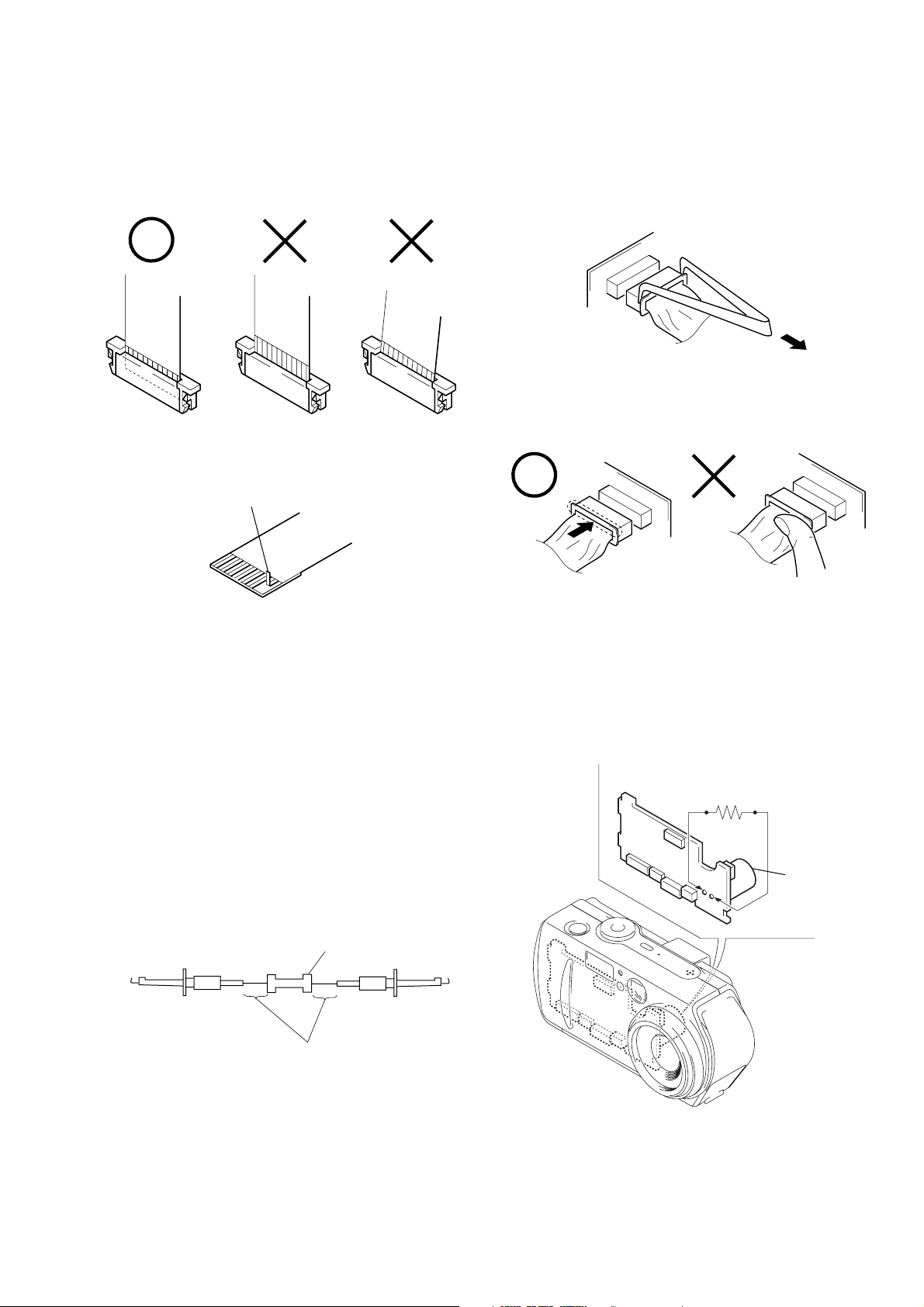
• NOTE FOR REPAIR
When installing a connector, don’t press down at wire of connector.
It is possible that a wire is snapped.
R:1 kΩ/1 W
(Part code:
1-215-869-11)
Capacitor
SERVICE NOTE
Make sure that the flat cable and flexible board are not cracked of
bent at the terminal.
Do not insert the cable insufficiently nor crookedly.
Cut and remove the part of gilt
which comes off at the point.
(Be careful or some
pieces of gilt may be left inside)
When remove a connector, don’t pull at wire of connector.
It is possible that a wire is snapped.
[Discharging of the DD-158 board’s charging capacitor
(C506)]
The charging capacitor (C506) of the DD-158 board is charged up
to the maximum 300 V potential.
There is a danger of electric shock by this high voltage when the
battery is handled by hand. The electric shock is caused by the
charged voltage which is kept without discharging when the main
power of the unit is simply turned off. Therefore, the remaining
voltage must be discharged as described below.
Preparing the Short Jig
T o preparing the short jig, a small clip is attached to each end of a
resistor of 1 kΩ /1 W (1-215-869-11).
Wrap insulating tape fully around the leads of the resistor to prevent electrical shock.
1 kΩ/1 W
Wrap insulating tape.
Discharging the Capacitor
Short-circuit between the positive and the negative terminals of
charged capacitor with the short jig about 10 seconds.
– 5 –
Page 6
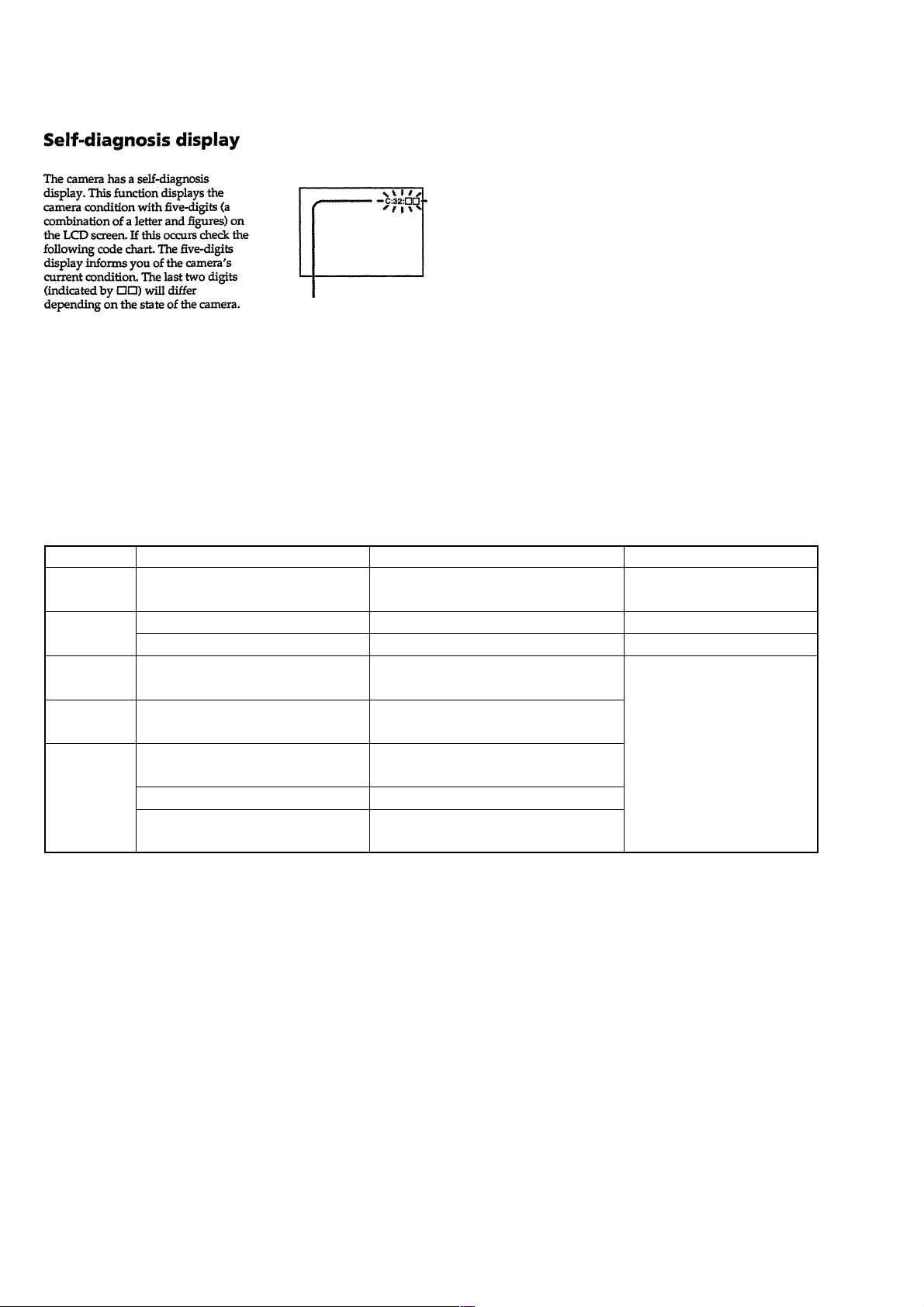
[Description on Self-diagnosis Display]
Self-diagnosis display
• C: ss: ss
You can reverse the camera malfunction yourself. (However , contact your Sony dealer or local
authorized Sony service facility
when you cannot recover from
the camera malfunction.)
• E: ss: ss
Contact your Sony dealer or local authorized Sony service facility.
Display Code
C:32:ss
C:13:ss
E:61:ss
E:91:ss
Countermeasure
Turn the power off and on again.
Format the “Memory stick”.
Insert a new “Memory Stick”.
Checking of lens drive circuit.
Checking of flash unit or replacement
of flash unit.
Use an “InfoLITHIUM” battery pack.
Insert a battery pack correctly. Battery pack is not inserted correctly. E:92:ss
Turn the power off and on again.
Cause
Trouble with hardware.
Unformatted memory stick is inserted.
Memory stick is broken.
When failed in the focus and zoom
initialization.
Abnormality when flash is being
charged.
Battery pack is not “InfoLITHIUM”
compatible.
Battery pack was installed or removed
when using the AC adaptor.
Caution Display During Error
SYSTEM ERROR
FORMAT ERROR
MEMORY STICK ERROR
—
– 6 –
Page 7
SECTION 1
GENERAL
DSC-P30/P50
This section is extracted from
instruction manual.
WARNING
To prevent fire or shock hazard, do
not expose the unit to rain or
moisture.
For the Customers in the
U.S.A.
This symbol is intended to
alert the user to the presence
of uninsulated “dangerous
voltage” within the
product’s enclosure that
may be of sufficient
magnitude to constitute a
risk of electric s h ock to
persons.
This symbol is intended to
alert the user to the presence
of important operating and
maintenance (servicing)
instructions in the literature
accompanying the
If you have any questions about this product,
you may call:
appliance.
Sony Customer Information Services Center
1-800-222-SONY (7669)
2
The number below is for the FCC related
matters only.
Declaration of Conformity
Trade Name: SONY
Model No.: DSC-P30
Responsible Party:Sony Electronics Inc.
Address: 680 Kinderkamack
Telephone No.: 201-930-6972
This device complies with Part 15 of the
FCC Rules. Operation is subject to the
following two conditions: (1) This
device may not cause harmful
interference, and (2) this device must
accept any interference received,
including interference that may cause
undesired operation.
Declaration of Conformity
Trade Name: SONY
Model No.: DSC-P50
Responsible Party:Sony Electronics Inc.
Address: 680 Kinderkamack
Telephone No.: 201-930-6972
This device complies with Part 15 of the
FCC Rules. Operation is subject to the
following two conditions: (1) This
device may not cause harmful
interference, and (2) this device must
accept any interference received,
including interference that may cause
undesired operation.
CAUTION
You are cautioned that any changes or
modifications not expressly approved in this
manual could void your authority to operate
this equipment.
Road, Oradell, NJ
07649 USA
Road, Oradell, NJ
07649 USA
Note:
This equipment has been tested and found to
comply with the limits for a Class B digital
device, pursuant to Part 15 of the FCC
Rules. These limits are designed to provide
reasonable protection against harmful
interference in a residential installation. This
equipment generates, uses, and can radiate
radio frequency energy and, if not installed
and used in accordance with the
instructions, may cause harmfu l interference
to radio communications. However, there is
no guarantee that interfere nce will not o ccur
in a particular installation. If this equipment
does cause harmful interference to radio or
television reception, which can be
determined by turning the equipment off and
on, the user is encouraged to try to correct
the interference by one or more of the
following measures:
— Reorient or relocate the receiving
antenna.
— Increase the separation between the
equipment and receiver.
— Connect the equipment into an outle t
on a circuit different from that to which
the receiver is connected.
— Consult the dealer or an experienced
radio/TV technician for help.
The supplied interface cable must be used
with the equipment in order to co mply with
the limits for a digital device pursuant to
Subpart B of Part 15 of FCC Rules.
For the Customers in the
U.S.A.
DISPOSAL OF LITHIUM ION
BATTERY .
LITHIUM ION BATTERY.
DISPOSE OF PROPERLY.
You can return your unwanted lithium ion
batteries to your nearest Sony Service
Center.
Note:
In some areas the disposal o f li thium ion
batteries in household or business trash may
be prohibited.
For the Sony Service Center near est yo u call
1-800-222-SONY (United States only)
Caution:
Do not handle damaged or leaking lithium
ion battery.
For the Customers in
Germany
Directive:EMC Directive 89/336/EEC,
92/31/EEC
This equipment complies with the EMC
regulations when used under the following
circumstances:
•
Residential area
•
Business district
•
Light-industry district
(This equipment complies with the EMC
standard regulations EN55022 Class B.)
Attention for the Customers in
Europe
This product has been tested and found
compliant with the limits sets out on the
EMC Directive for using connection cables
shorter than 3 meters.
Attention
The electromagnetic fields at the s pe cific
frequencies may influence the pictu re a nd
sound of this camera.
“Memory Stick”
N50
3
For the Customers in the
U.S.A. and Canada
THIS CLASS B DIGITAL DEVICE
COMPLIES WITH PART 15 OF THE
FCC RULES AND THE CANADIAN
ICES-003 OPERATION IS SUBJECT
TO THE FOLLOWING TWO
CONDITIONS:
(1) THIS DEVICE MAY NOT CAUSE
HARMFUL INTERFERENCE, AND
(2) THIS DEVICE MUST ACCEPT
ANY INTERFERENCE RECEIVED,
INCLUDING INTERFERENCE THAT
MAY CAUSE UNDESIRED
OPERATION.
Be sure to read the following
before using your camera
Trial recording
Before you record one-time events, you may
want to make a trial recording to make sure
that the camera is working correctly.
No compensation for contents of
the recording
Contents of the recording cannot be
compensated for if recording or playback is
not possible due to a malfunction of your
camera or recording medium, etc.
Notes on image data compatibility
•
This camera conforms with the Design
Rules for Camera File Systems universal
standard establ is hed by the JEITA (Japan
Electric and Information Technology
Industries). You cannot play back on your
camera still images recorded on other
equipment (DCR-TRV890E/TRV900/
TRV900E, DSC-D700, DSC-D770) that
does not conform with this universal
standard. (These models are not sold in
some areas.)
•
Playback of images recorded with your
camera on other equipment and playback
of images recorded or edited with other
equipment on your camera are not
guaranteed.
Precaution on copyright
Television programs, films, video tapes, and
other materials may be copyrighted.
Unauthorized recording of suc h ma terials
may be contrary to the provision of the
copyright laws.
Do not shake or strike the camera
In addition to malfunctions and inability to
record images, this ma y render the
“Memory Stick” unusable or image data
breakdown, damage or loss may occur.
Do not aim the camera at the sun
or other bright light
This may cause irrecoverable damage to
your eyes.
LCD screen, LCD finder (only
models with a finder) and lens
•
The LCD screen and the LCD finder are
manufactured using extremely highprecision technology so over 99.99% of
the pixels are operational for effective use.
However, there may be some tiny black
points and/or bright points (white, red,
blue or green in color) that constantly
appear on the LCD screen and the LCD
finder. These points are normal in the
manufacturing process and do not affect
the recording in any way.
•
Be careful when placing the camera near a
window or outdoors. Exposing the LCD
screen, the finder or the lens to direct
sunlight for long periods may cause
malfunctions.
Notes on batteries
Be careful when removing the b atteries, as
they may be hot after the camera is used for
long periods.
Do not get the camera wet
When taking pictures outdoors in the rain or
under similar conditions, be careful not to
get the camera wet. If moisture
condensation occurs, refer to page 71 and
follow the instructions on how to remove it
before using the camera.
Back up recommendation
To avoid the potential risk of data loss,
always copy (back up) data to a disk.
When the camera is used for long
periods
Note that the camera body may become hot.
4
5
1-1
Page 8

Introduction
Checks the image after recording images
Recording still images:
page 19
Playing back still images:
page 28
Deleting images (DELETE):
page 62
Captures images with your computer
You can copy images onto your computer and view and modify images or attach
images to e-mail on your computer using the supplied USB cable and application
software.
Viewing images using a personal computer: pag e 30
Recording still images for e-mail (E-MAIL): page 48
Getting started
Identifying the parts
See the pages in parent hes es for details of operation.
Records a moving picture (MPEG Movie or Clip Motion)
according to your purpose
Recording moving images (MPEG
MOVIE): page 26
Selects the recording mode from various types of recordings
according to your situation
Creating Clip Motion Files: page51
Recording text documents (TEXT): page 49
Recording still images as uncompressed files (TIFF): page50
6
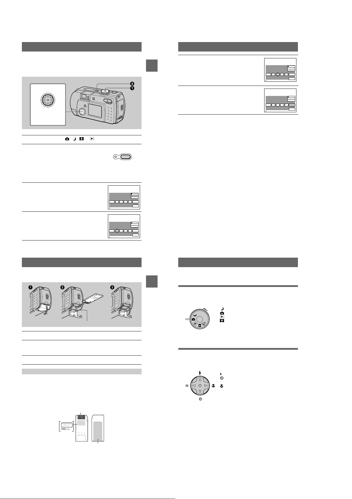
Attaching the str ap
Getting started
A POWER button/lamp (15)
Press and hold down this button
for approximately one second to
turn on the came ra.
B Mode dial (18) (39)
: To record in TWILIGHT
mode
: To record still images
: To playback or edit
images
: T o record moving images
or Clip Motion images
SET UP:To set the setup items
C Shutter button (19) (27)
D Flash (24)
E Photocell window for flash
Do not block while recording with
the flash.
F Self-timer (23) (27)/
AF illuminator (25)
G Lens cap (supplied)
Be sure to remove the lens cap
before recording.
H Finder window
I Beep/shutter sound holes
J Lens
K Jack cover
L USB jack (32) (34)
M VIDEO OUT jack (61)
N Tripod receptacle (bottom
surface)
Use a tripod with a screw length of
less than 5.5 mm (7/32 inch). You
will be unable to firmly secure the
camera to tripods having longer
screws, and may damage the
camera.
O RESET button (75)
8
Preparing the power supply
Installing the supplied batteries or an optional
battery pack
Your camera operates only with the following batteries.
•
Two size AA alkaline batteries (supplied)
•
“InfoLITHIUM” (S series) battery pack (NP-FS11) (not supplied)
•
Two size AA nickel metal hydride batteries (not supplied)
•
Two size AA nickel-cadmium batteries (not supplied)
The “InfoLITHIUM” ba ttery pack is recommen ded for longer operatin g times. Note
that in this Operating Instructions, “batteries” refers to siz e AA al ka lin e batteries.
Batteries
A Finder
Self-timer/recording lamp (red)
AE/AF lock lamp (gr e e n)
/CHG (flash charge/battery
charge) lamp (orange) (24)
B MENU button (40)
C DC IN jack cover (12) (14)
D DC IN jack (12) (14)
E Control button (18) (39)
F LCD screen
G DISPLAY/LCD ON/OFF button
(21)
H Zoom button (INDEX button
during playback ) ( 2 2 )
I Hook for lens cap/wrist strap
J OPEN switch
K Battery cover
L Access lamp (17)
M “Memory Stick” cover
“InfoLITHIUM” battery p ack (not supplied)
Insert the battery pack with the v mark facing toward the bat tery compartment.
Open the battery cover.
1
Open the cover while sliding the OPEN switch in the direction of the arrow.
9
10
1-2
Page 9
Install the batteries.
2
Insert the two size AA batteries with the 3 and # ends facing as illustrated. Be
careful not to insert the batteries facing the wrong way.
Close the battery cover.
3
Pressing the batteries with the cover, close the cover firmly until it clicks into
place.
To remove the batteries
Open the battery cover with the battery cover side facing upward and remove the
batteries. Be careful not to drop the batteries when removing them.
Power save mode
When operating the camera with batteries, set POWER SAVE in the SET UP screen
to ON to extend the battery life. The factory setting is ON (page70).
See page 88 for more in formation on power save mode.
Auto power-off function
If you do not operate the cam era for about three minutes during recording or
playback, the camera turns off automatically to prevent wearing down the battery. To
use the camera again, pres s the P O WE R b utt on to tu rn on the camera agai n. The auto
power-off function only operates when the camera is operating using a battery pack.
The auto power-off also will not operate when playing back moving images or
playing back a slide show (page 60), or when a connector is plugged into the USB
jack or the DC IN jack.
* What is “InfoLITHIUM”?
“InfoLITHIUM” is a lithium ion battery pack which can exchange information such as battery
consumption with compatible vide o equ ipment. This unit is compatible with the
“InfoLITHIUM” battery pack (S series). “InfoLITHIUM” S series battery packs have the
mark. “InfoLITHIUM” is a trademark of Sony Corporation.
NP-FS11 battery pack (not supplied)
When you record images in an extremely cold location or using the LCD screen, the
operating time becomes short. When using the camera in an ex tremely cold location,
place the battery pack in your pocket or other place to keep it warm , t hen insert the
battery pack into the camera just before recording. When using a pocket heater, take
care not to let the heater di rectly contact the battery.
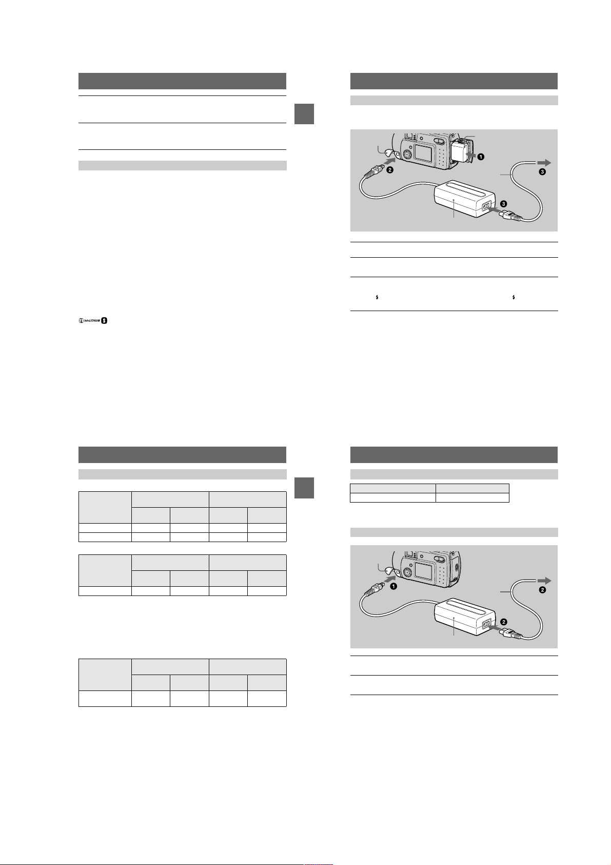
Charging the battery pack (not supplied)
You cannot charge the battery pack while your camera is turned on. Be sure to turn
Getting started
off your camera.
DC IN jack
cover
AC-LS1A AC power adaptor (not supplied)
Insert the battery pack into your camera.
1
Open the DC IN jack cover and connect the DC connecting cable to
2
the DC IN jack of your camera with the v mark facing up.
Connect the power cord (mains lead) to the AC power adaptor (not
3
supplied) and then to a wall outlet (mains).
The /CHG lamp lights up when charging begins. When the /CHG lamp goes
off, charging is completed.
Battery pack (S series)
(not supplied)
To the wall outlet (mains)
Power cord
(mains lead)
After charging the battery pack
Disconnect the AC power adaptor fr om the DC IN jack on your camera.
Battery remaining indicator
When using an optional “InfoLITHIUM” battery pack, the LCD screen on the
camera shows the rema in in g time for which you can still r ec or d or play back images.
This indication may not be ent i rely accurate depending on th e conditions of use and
the operating environment.
Charging of 10°C to 30°C (50°F to 86°F) circumstances is recommended.
When using size AA alkaline batteries, the remaining time is not shown.
Note
When you turn the LCD screen on and off, it takes about one minute for the correct battery
remaining time to appear.
Battery life and number of images that can be recorded/played back
Still image recording*
SONY alkaline batteries
(supplied)
Battery life
(min.)
Number of
images
NP-FS11 (not supplied)**
Battery life
(min.)
Number of
images
LCD screen ON Approx. 30 Approx. 600 Approx. 90 Approx. 1800
LCD screen OFF Approx. 60 Approx. 1200 Approx. 120 Approx. 2400
Still image playback***
SONY alkaline batteries
(supplied)
Battery life
(min.)
Number of
images
NP-FS11 (not supplied)**
Battery life
(min.)
Number of
images
LCD screen ON Approx. 60 Approx. 1200 Approx. 120 Approx. 2400
Approximate battery lif e and number of images that can be recorded/played ba ck
640×480 image size, standard picture quality, no flash, and in NORMAL recording
mode.
Recording at about 3-second intervals with the power save mode off (when continuous
∗
recording, the power save mode does not operate effectively.)
When using a fully charged battery pack at a temperature of 25°C (77°F).
∗∗
Playing back single images in order at about 3-sec ond intervals
∗∗∗
Moving image recording
SONY alkaline batteries
(supplied)
LCD screen
Continuous
recording
Approximate recor ding time in 160×112 imag e size.
When using a fully charged battery pack at a temperature of 25°C (77°F).
∗
Notes
•
The camera may not operate in an extremely cold location when using alkaline batteries.
Even when using an “InfoLITHIUM” battery pack (not supp l ied), the battery life and number
of images will be decreased if you use your camera at low temperatures, use the flash ,
repeatedly turn the power on/off or use the zoom.
•
The numbers of images shown on tables above are as a guide. The numbers may be smaller
depending on conditions.
•
The capacity of the “Memory Stick” is limited. The ab ove figures are a guide when you
continuously record/play back while replaci ng the “M em or y S tic k. ”
•
When LCD BACKLIGHT is set to BRIGHT, th e battery life and number of images will be
decreased.
OFF (min.)
Approx. 60 Approx. 30 Approx. 120 Approx. 90
LCD screen
ON (min.)
NP-FS11 (not supplied)*
LCD screen
OFF (min.)
LCD screen
ON (min.)
11
13
Getting started
12
Charging time
Battery pack Full charge (min.)
NP-FS11 (not supplied) Approx. 180
Approximate time to charge a completely discharged battery pack using the
AC-LS1A AC power adaptor (not supplied) a t a temperature of 25°C (77°F).
Using the AC power adaptor (not supplied)
DC IN jack
cover
To the wall outlet (mains)
Power cord
(mains lead)
AC-LS1A AC power adaptor (not supplied)
Open the DC IN jack cover and connect the DC connecting cable to
1
the DC IN jack of your camera with the v mark facing up.
Connect the power cord (mains lead) to the AC power adaptor (not
2
supplied) and then to a wall outlet (mains).
Using a car battery
Use Sony DC adaptor/charger (not supplied).
Using your camera abroad
For details, see page74.
When using the AC power adaptor
Be sure to use it near the wall outlet. If a malfunction occurs, disconnect the plug
from the wall outlet.
14
1-3
Page 10
Setting the date and time
When you first use your camera, set the date and time. If these are not set, the
CLOCK SET screen appear s whenever you turn on your camera.
Control button
Select the item with
, then set with
vVbB
the center z.
Set the mode dial to , , or
1
Press and hold down the POWER button for
2
approximately one second to turn on the
power.
The POWER ON/OFF (CHG) lamp (green) lights
up.
The CLOCK SET screen appears on the LCD
screen.
To change the date and time, set the mode dial to
SET UP (page 69) and perform th e procedure from step 3.
Select the desired date display format with
3
on the control button, then press the
v/V
center z.
Select from [Y/M/D] (year/month/da y), [M/D/Y]
(month/day/year) or [D/M/Y] (day/month/year).
Select the year, month, day, hour or minute
4
item you wa nt to se t w it h b/B on the control
button.
The item to be set is indicated with v/V.
CLOCK SET
2001
OK
CLOCK SET
2001
OK
/:/
/:/
POWER
ON/OFF(CHG)
1
12 00
1
1
12 00
1
Y / M / D
M / D / Y
D / M / Y
AM
CANCEL
Y / M / D
M / D / Y
D / M / Y
AM
CANCEL
Set the numeric value with v/V on the
5
control button, then press the center z to
enter it.
Getting started
OK
OK
After entering the number, v/V moves to the next
item.
If you selected [D/M/Y] in step 3, set the time on a
24-hour cycle.
Select [OK] with B on the control button,
6
then press the center z at the desired
moment to begin clock movement.
The date and time are entered.
To cancel the date and time setting
Select [CANCEL] with v/V/b/B on the control button, then press the center z.
Note
If the rechargeable button battery is ever fully discharged (page 72), the CLOCK SET screen will
appear again. When this happens, rese t th e da te and time by starting from step 3 above.
CLOCK SET
2001
OK
CLOCK SET
2001
OK
/:/
/:/
Y / M / D
M / D / Y
D / M / Y
OK
1
12 00
7
AM
CANCEL
Y / M / D
M / D / Y
D / M / Y
OK
4
10 30
7
PM
CANCEL
Inserting the “Memory Stick”
Access lamp
Open the “Memory Stick” cover.
1
Insert the “Memory Stick.”
2
Insert the “Memory Stick” with the B mark facing toward the battery
compartment as illustrated until it clicks.
Close the “Memory Stick” cover.
3
Removing the “Memory Stick”
Open the “Memory Stick” cover, then press the “Memory Stick” once lightly.
Notes
•
Insert the “Memory Stick” firmly until it clicks, otherwise a message such as “MEMORY
STICK ERROR” will be displayed.
•
Never remove the “Memory Stick” or turn off the power while the access lamp is lit up.
•
Y ou can not record or edi t images o n a “Mem ory Stick” if the erasure prevention switch is set to
the LOCK position.
Connector
15
Getting started
16
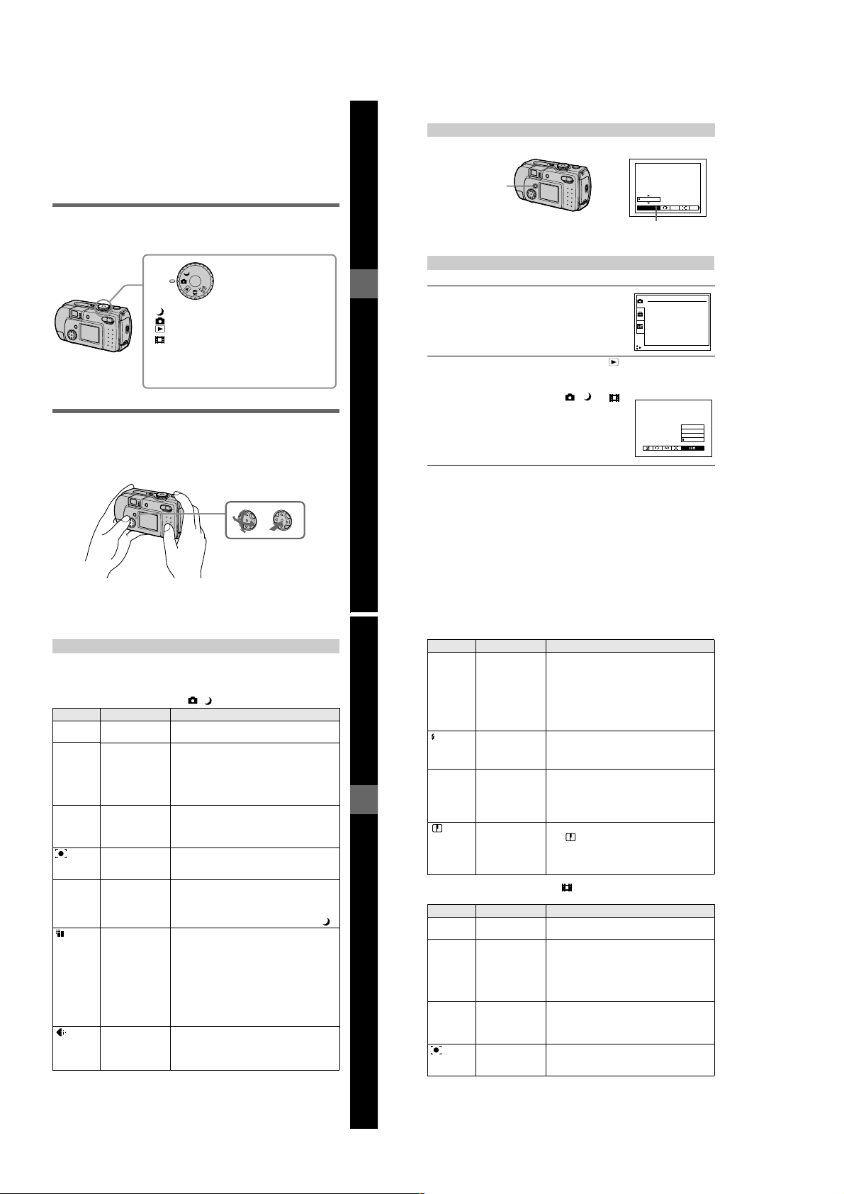
Basic operations
Recording
B
Basic operations
How to use the mode dial
The mode dial switches the function which is used for recording, playback, or
editing. Set the dial as follows before starting to operate your camera.
: To record still images in TWIL IGHT mode
: To record still images
: To play back or ed it images
: To record moving images or Clip Motion images
SET UP: To display the setup items (The SET UP pos ition
changes the settings of infrequently-used
items.)
How to use the control button
When the menu is not displ ayed, the control button is used to pe rform the following
operations.
(v): Recording with flash
(V): Recording with self-timer
7
(b): Checkin g the last recorded image
(B): Recording close subjects
When you select above functions with the control button while recording with the
LCD screen turned off, the LCD screen lights for approximatel y 2 seconds and the
selected function icon appears on the screen. The LC D screen also lights
automatically when the MENU button is pressed, but in this case the LCD screen
does not turn off automatically.
Erasure
prevention
switch
The position and shape of the erasure prevention switch may differ depending on the type s of
“Memory Stick” used.
Label space
17
18
1-4
Page 11
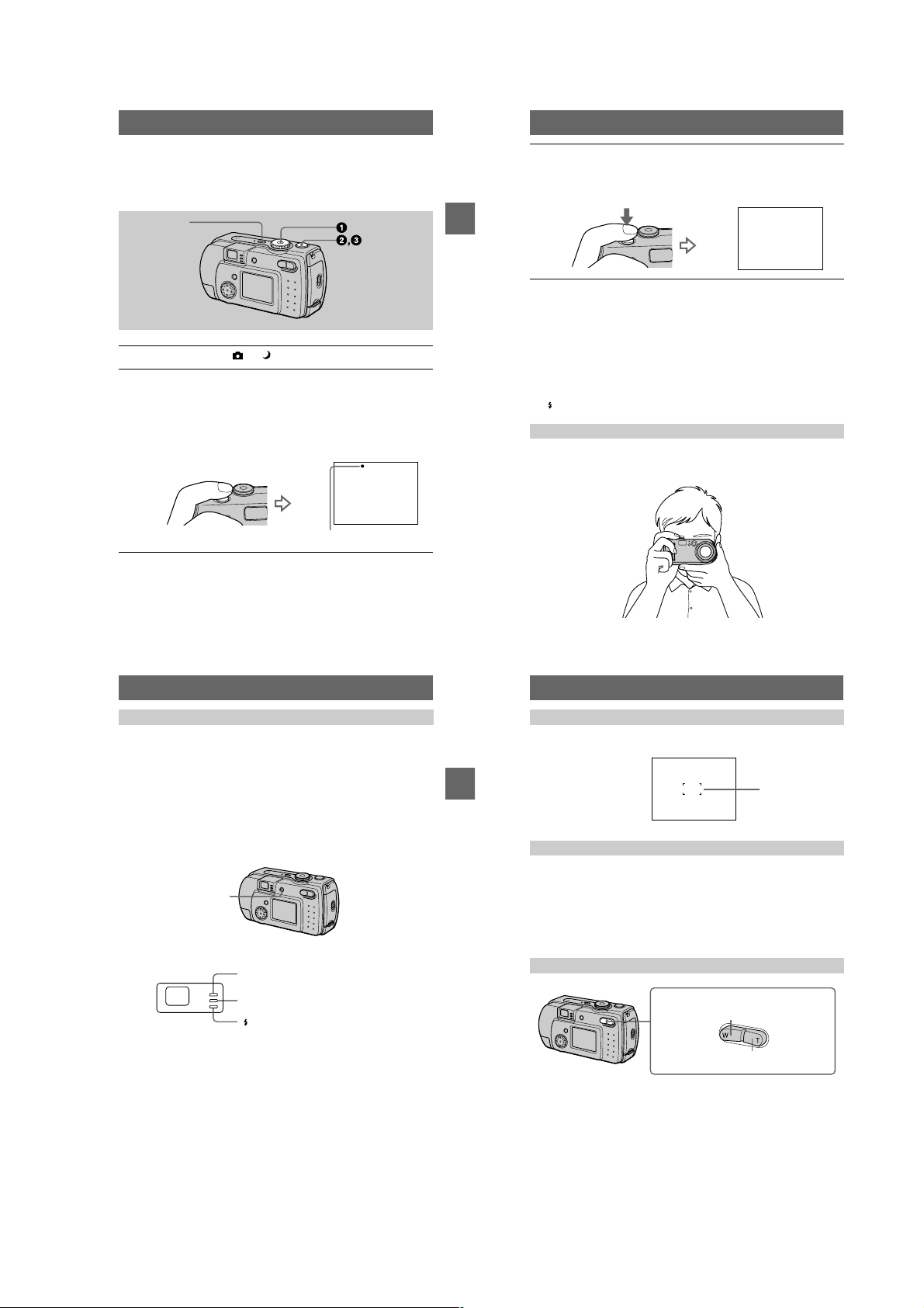
Recording still images
Still images are recorded in JPEG format.
Before recording still images, press the POWER button to turn on the power and
insert a “Memory Stick.”
POWER
Set the mode dial to or .
1
Press and hold the shutter button halfway down.
2
The image freezes momentarily, but is not yet recorded. While the AE/AF lock
indicator z is flashing, the camera automatically adj us ts the exposure and
focus of the captured imag e. When the camera finishes the automatic
adjustments, the AE/AF lock indicator z stops flashing, then light s up and the
camera is ready for recording.*
If you release the shut ter button, the record ing will be canceled.
AE/AF lock indicator (green) flashes t lights up
BB
B
B
Recording
Press the shutter button fully down.
3
The shutter sounds.
“RECORDING” appears on the LCD screen, and the image will be recorded on
the “Memory Stick.” When “RECORDING” disappears, you can record the
next image.
RCORI
If the flashing AE/AF lock indicator changes to flashing slowly, the subject may be difficult to
∗
focus on (dark, poor contrast) or the subject may be extrem el y cl ose . Re le as e th e shu tte r
button, then focus again.
The number of images you can record on a “Memory Stick”
See pages 46 and 48 to 52.
Notes
•
When recording a bright subject, the LCD screen color may change after AE/AF lock, but this
does not affect the recorded imag e.
•
When you press the shutter button fully down at once in step 2, the camera starts recording
after the automatic adjustment is complete. However, the recording cannot be carried out while
the /CHG lamp (page 21) is flashing. (During this time, the camera is charging the flash.)
Holding the camera correctly
Hold the camera so that yo ur fingers do not block the flash and do not t ouc h the lens
portion when recording images.
19
Recording images with the finder
You can extend the battery time by turning off the LCD screen and recording using
the finder.
Each time you press DISPLAY/LCD ON/OFF, the status of the LCD screen changes
as follows:
See page 85 for a detailed description of the indicated items.
The LCD backlight is turned on.
(All the available indicators are turned on.)
r
The LCD backlight is turned on.
(Warning messages are turned on.)
r
The LCD backlight is turned off.
DISPLAY/LCD ON/OFF
Indicators in the finder
Notes
•
You cannot check the entire recording range with the finder. Recording with the LCD screen is
recommended when it is necessary to correctly unde r sta nd the recording range.
•
Because of the difference of the portion of the finder and lens, use the LCD screen whe n you
record a subject closer than 1 m (3 1/4 feet).
•
When [DEMO] is set to [ON] in the S ET UP sett i ngs, yo u c ann ot tur n off the LCD screen once
the demonstration starts.
•
You cannot turn off the LCD backlight when setting in SET UP and when displaying the menu.
•
You cannot turn off the self-timer indicators and some of the indicators used in advanced
operations.
•
The indicators on the LCD screen are not recorded.
Recording lamp (red)
AE/AF lock lamp (green)
/CHG lamp (orange)
BB
B
B
Recording
20
Recording with the LCD screen
When recording w it h the LCD screen, align the AF frame in the center of the screen
with the subject.
AF frame
Checking the last recorded image (Quick Review)
You can check the last recorded image by clearing the menu from the screen
(page 40) and pressing b (7) on the control b utton. (You can perform this operation
even when the LCD screen is off.)
To return to the norma l recording mode: press lightly on the shutter button or
press b (7) again.
To delete the image: 1. Press MENU. 2. Select [DELETE] with B on the control
button, then press the center z. 3. Select [OK] with v on the control button, then
press the center z.
Using the zoom feature
Zoom button
W side: for wide-angle (subject appears
farther away)
T side: for telephoto (subject appears closer)
If you cannot get a sharp focus on a close subject
Press the zoom W button repeatedly and move closer to the subject until the focus is
sharp.
Minimum focal distance to the subject
W side: About 25cm (9 27/32 inches) or more
T side: About 80 cm (31 1/2 i n ches) or more
To record even closer subjects, see page 53.
21
22
1-5
Page 12
Digital zoom function
VING IMA
GE:
This camera has a digital zoom function.
Digital zoom enlarges the image by digital processing and it starts to function when
zoom exceeds 3×.
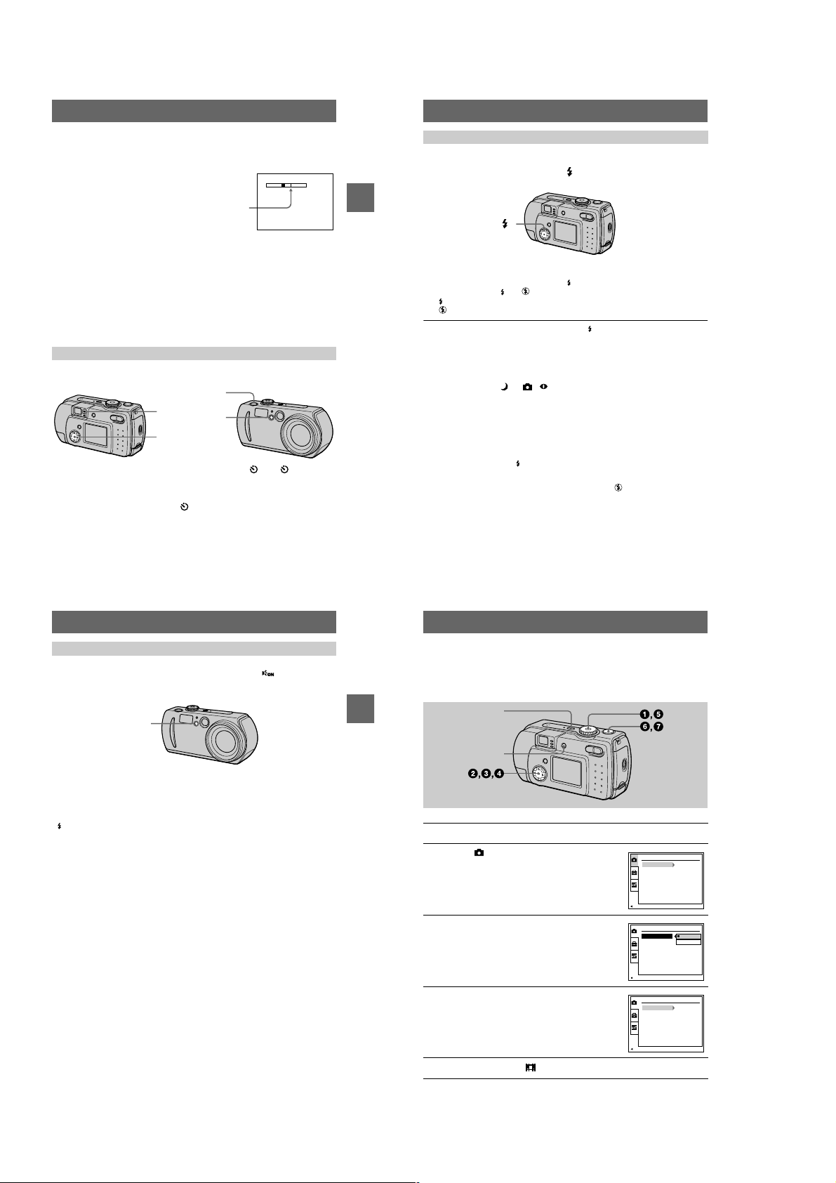
Recording images with the flash
The factory setting is auto (no indicator). In this mode, the flash automatically
strobes when the surroundings is dark. To change the flash mode, clear the menu
(page 40), then press the
indicator appears on the LCD screen.
control button v (
) repeatedly so that the flash mode
The T side of the bar shows the
digital zooming zone.
Using digital zoom
•
The maximum zoom magnification is 6×.
•
Digital zooming dete ri or at es the picture quality. When digital zoom is not
necessary, set [DIGITA L ZOOM] to [OFF] in the setup settings (page 69).
Notes
•
Digital zoom does not work for moving images.
•
Use the LCD screen when using digital zoom function. Digitally zoomed images do not appear
in the finder.
•
The AF frame (page85) does not appear on the LCD screen.
Using the self-timer
When you use the self-timer function, the subject is recorded about 10 seconds after
you press the shutte r butt on.
Shutter button
Self-timer lamp
Control button
Clear the menu (page 40), then press the control button V ( ). The (self-timer)
indicator appears on t he LCD scre en, an d about 10 seco nds afte r you pr ess the s hutter
button, the subject is re corded. The self-timer lamp flashes an d t he beep sounds after
you press the shutter button until the shutter is released. To cancel the self-timer
recording, press the control button V ( ) again.
23
BB
B
B
Recording
Control button v ()
Each time you press the control button v ( ), the indicator changes a s follows.
(No indicator) t t t (No indicator)
Forced flash: The flash strobes regardless of the surrounding brightness.
No flash: The flash does not strobe.
You can change the brightness of the flash with [ ±] (FLASH LEVEL) in the menu
settings (page 42).
To reduce the red-eye phenomenon
Set [RED EYE REDUCTION] to [ON] in the setup settings, the flash strobes before
recording to reduce the red-eye phenomenon (page 69). When [ON] is selected and
the mode dial is set to or , appears on the LCD screen.
Notes
•
When [ISO] is set to [AUTO] in the menu settings, the recommended shooting distance using
the built-in flash is 0.3 m to 2.0 m (11 13/16 inches to 6 feet 6 3/4 inches). When it is not set to
[AUTO], the flash may be ineffective even if the flash level is changed.
•
Red-eye reduction may not produce the desired effects depending on individual differences, the
distance to the subject, if the subject does not see the pre-strobe, or other conditions.
•
The flash effect is not obtained easily when you use forced flash in a bright locat ion.
•
While charging the flash, the /CHG lamp flashes. After the charging is complete, the lamp
goes out.
•
The flash does not function when recording moving images (excludi ng C lip Motion).
•
When you record images i n a dark place with the camer a set to
becomes slow, so using a tripod is recommended to prevent shaking.
(no flash), the shutter speed
24
Recording images with the AF illuminator
The AF illuminator is fill light to focus on a subject easi ly und er dark conditions. Set
[AF ILLUMINATOR] (page 69) to [ON] in the setup settings, appears on the
LCD screen and the AF illuminator emits light when the shutter button is pressed
halfway. It keeps emitting light until the focus is locked.
AF illuminator
Notes
•
If AF illuminator light does not reach the subject sufficiently or the subj ect ha s no c ontr a st,
focus will not be achieved. (Approximate distance up to 2.0 m (6 feet 6 3/4 inches) is
recommended.)
•
In TWILIGHT mode (page 47), the AF illuminator will emit only when the flash mode is set to
(Forced flash).
•
Focus is achieved as long as AF illuminator light reaches to the subje ct even if its light is
slightly out of the middle position of the subje c t.
•
The AF illuminator is a very bright light. Although it is safe to use, avoid shining it directly into
someone’s eyes at a close distance.
BB
B
B
Recording
Recording moving images
Moving images are reco rded in MPEG format ( page 38).
To recor d moving images, press the POWER button to turn on the power and in sert a
“Memory Stick.”
DISPLAY/LCD ON/OFF
1
2
3
4
5
POWER
Set the mode dial to SET UP.
Select [ ] (CAMERA) with v/V on the
control button, then press B.
Select [MOVING IMAGE] with v/V on the
control button, then press B.
Select [MPEG MOVIE] with v/V on the
control button, then press the center z.
Set the mode dial to .
CAMERA
MOVING IMAGE:
DATE/TIME:
DIGITAL ZOOM:
RED EYE REDUCTION:
AF ILLUMINATOR:
PAGE SELECT
CAMERA
MOMOVING IMA
DATE/TIME:
DIGITAL ZOOM:
RED EYE REDUCTION:
AF ILLUMINATOR:
OK
CAMERA
MOVING IMAGE:
DATE/TIME:
DIGITAL ZOOM:
RED EYE REDUCTION:
AF ILLUMINATOR:
PAGE SELECT
MPEG MOVIE
OFF
OFF
OFF
ON
GE:
MPEG MOVIE
CLIP MOTION
MPEG MOVIE
OFF
OFF
OFF
ON
25
26
1-6
Page 13
Press the shutter button fully down.
FILE BACK/NEXT
10:30
PM
2001 7 4100-0028
6/8
640
6
“REC” appears on the LCD screen, and the image is recorded on the “Memory
Stick.”
Sound cannot be recorded with moving images.
Press the shutter button fully down again to stop recording.
7
The recording stops. Or, the recording stops when the “Memory Stick” is full.
For details on the image size, see “Setting the image size (IMAGE SIZE)” on
page 45”.
Using the self-timer
When you use the self-timer function, the subject is recorded about 10 seconds after
you press the shutte r butt on.
Clear the menu (page 40), then press the control button V ( ). The (self-timer)
indicator appears on the LCD screen, and the recording starts about 10 seconds after
you press the shutter button. The self-timer lamp flashes and the beep sounds after
you press the shutter button until the shutter is released. To stop the self-timer
recording, press the control button V ( ) again.
LCD screen indicators during recording
Each time you press DSPL /LCD ON/OFF, the status of t he LCD screen changes as
follows: all indi cators on t indicators off t LCD screen off.
These indicators are not recorded. See page 86 for a detailed description of the
indicators.
Note
If you remove the battery or otherwise turn off the power partway through a recording, the
moving image recorded thus far is not saved. When the battery low mark E appears while
operating the camera with batt er ies, stop the recording at this poi nt be fo re the batteries
completely run out.
BB
B
B
Recording
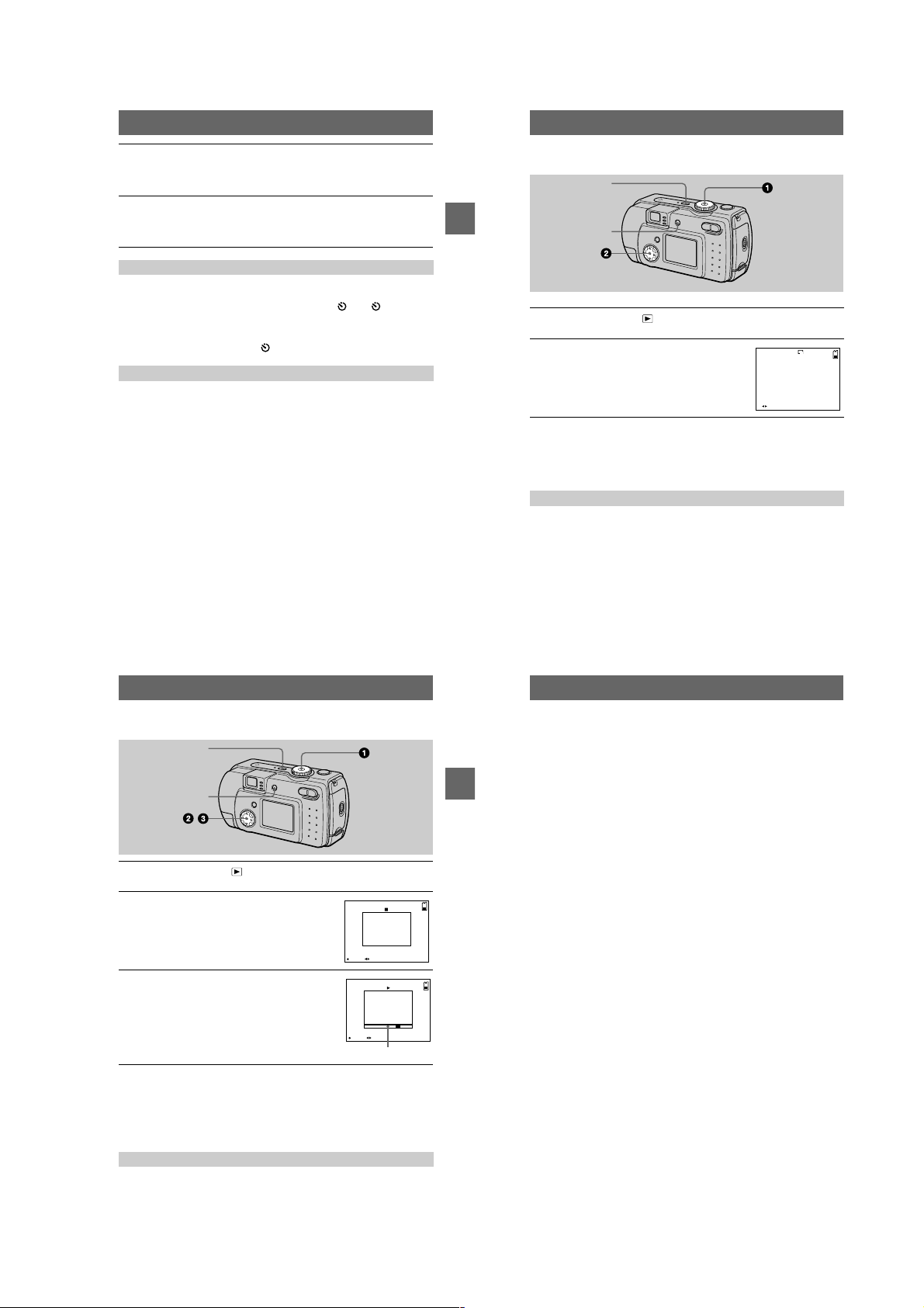
Playback
B
Playing back still images
DISPLAY/LCD ON/OFF
1
2
Notes
•
•
Each time you press DSPL/LCD ON/OFF, the statu s of the LCD screen changes as
follows: all indicators on t indicators off t LCD screen off.
See page 87 for a detailed description of the indicators.
POWER
Set the mode dial to .
The last recorded image (still or moving) appears on th e LC D screen.
Select the desired still image with the
control button b/B.
: To display the preceding image.
b
: To display the next image.
B
You might not be able to correctly pl ay b ack images reco rded with this camera on other
equipment.
You cannot play back on this camera images larger than the maximum image size that can be
recorded with this camera.
LCD screen indicators during still image playback
Playing back moving images
DISPLAY/LCD ON/OFF
1
2
3
To pause playback
Press the center z on the control button to stop the pl ayback.
To advance or rewind the moving image
Press the control button b/B during playback.
To return to the normal playback, press the center z on the control button.
LCD screen indicators during moving image playback
Each time you press DSPL /LCD ON/OFF, the status of t he LCD screen changes as
follows: all indi cators on t indicators off t LCD screen off.
See page 87 for a detailed descr i pt i on of the indicators.
POWER
,
Set the mode dial to .
The last recorded image (still or moving) appears on the LCD screen.
Select the desired moving image with the
control button b/B.
Moving images are display ed one-size smaller than
still images.
: To display the preceding image.
b
: To display the next image.
B
Select the center z to start the playback.
The moving image is played back.
During playback , B (playback) appears on the LCD
screen.
To advance or rewind, press the control button b/B
during playback .
FILE BACK/NEXTPLAY
STOP REV/CUE
Playback bar
2001 7 4MOV 00001 10:30 PM
6/8
6/8
27
29
28
Viewing images using a personal
computer
You can view data recorded with your camera on a personal computer, modify and
attach it to e-mail using application software. This section describes the method for
viewing images on a personal computer using the supplied USB cable.
There are two ways to make the USB connection, which are the norma l co nnection
BB
B
B
Playback
and the PTP connection (page 70). This is set using [USB CONNECT] in the setup
settings. However, any OS does not conform to [PTP] as of M ar ch, 2001. Here
describes the way using the [NORMAL] setting.
The factory setting of USB mode is [NORMAL].
The mode can be checked and set as follows.
1
Set the mode dial to SET UP.
2
Select [SETUP2] with v/V, then press B.
3
Select [USB CONNECT] with v/V, then press B.
4
Select the connection mode with v/V.
The USB cable is used to connect the camera to a personal computer so that
operations can be performed on image files recorded in a “Memory Stick” from the
personal computer.
In order to use the USB cable, a USB driver must be installed in the personal
computer beforehand.
Be sure to also refer to the operation manuals for your personal computer and the
application soft w a r e .
Notes
•
Data recorded with your camera is stored in the following formats. Make sure that applications
that support these file formats are installed on your per sona l computer.
— Still images (other than TEXT mode, uncompressed mode and Clip Motion): JPEG format
— Moving images: MPEG format
— Uncompressed mode still images: TIFF format
— TEXT mode/Clip Motion: GIF format
•
Depending on your application software, the file size may increase when you open a still image
file.
•
When you copy the image to the camera from your comp u ter, which was modified with a
retouching software and was converted to another file format, the “FILE ERROR” message
may appear and you may be unable to open the image.
•
Depending on your application software, only the first frame of the Clip Mot ion file may be
played back.
Communications with your computer (for Windows only)
Communications between your camera and your computer may not recover after recovering
from Suspend or Sleep.
•
When connecting the camera to a computer, use a fully charged “InfoLITHIUM” battery pack
(not supplied) or the AC power adapter (not supplied). Do not use batteries.
30
1-7
Page 14
Recommended computer en vironment
Recommended Windows environment
OS: Microsoft Windows 98 , Windows 98SE, Windows 2000 Professional, Windows
Millennium Edition
The above OS is required to be instal led at the factory .
Operation is not assured in an environment upgraded to the operating sy ste ms described
above.
CPU: MMX Pentium 200 MHz or faster
The USB connector must be provided as standard.
Recommended Macintosh environment
Macintosh computer with the Mac OS 8.5.1/8.6/9.0/9.1 standard installation
However, note that the update to Mac OS 9.0/9.1 should be used for the following models.
•
iMac with the Mac OS 8.6 factory pre-installed and a slot loa ding type CD-ROM drive
•
iBook or Power Mac G4 with the Mac OS 8.6 factory pre - inst a lle d
The USB connector must be provided as standard.
QuickTime 3.0 or newer must be installed (to play back moving pictures).
Notes
•
If you connect two or more USB equipment to a single persona l co mputer at the same time,
some equipment may not operate depending on the type of USB eq uipment.
•
Operations are not guaranteed when using a hub.
•
Operations are not guaranteed for all the recommended computer environments menti o n ed
above.
•
Microsoft and Windows are either registered trademarks or trademarks of Microsoft
Corporation in the United States and /or oth er countries.
•
Macintosh and Mac OS, QuickTime are either registered trademarks or trademarks of Apple
Computer, Inc.
•
All other product names mentioned herein may be the tra de ma r ks or register ed trade marks of
their respective companies. Furthermore, “™” and “®” are not mentioned in each case in this
manual
Installing the USB driver
Before connecting your camera to your personal computer, install the USB driver to
the computer. The USB driver is included with the application software in the CDROM which is supplied with your camera.
Be sure to complete installation of the USB driver before connecting the
USB cable. If you connect the USB cable first, you will be unable to
BB
B
B
Playback
install the USB driver properly.
See page 80 for corrective measures if the USB cable was connected before installing
the driver and the driver software could not be ins ta ll ed correctly.
For Windows 98/98SE/Me and Windows 2000 users
Turn on your personal computer and allow Windows to load.
1
Do not connect the USB cable in this step.
Insert the supplied CD-ROM in the CD-ROM drive of your personal
2
computer.
The application software sc r een appears.
Click “USB Driver Installation for Windows 98/98SE/Me and
3
Windows 2000”.
USB driver installation starts.
Follow the on-screen messages to install the USB driver.
4
Your personal computer may restart.
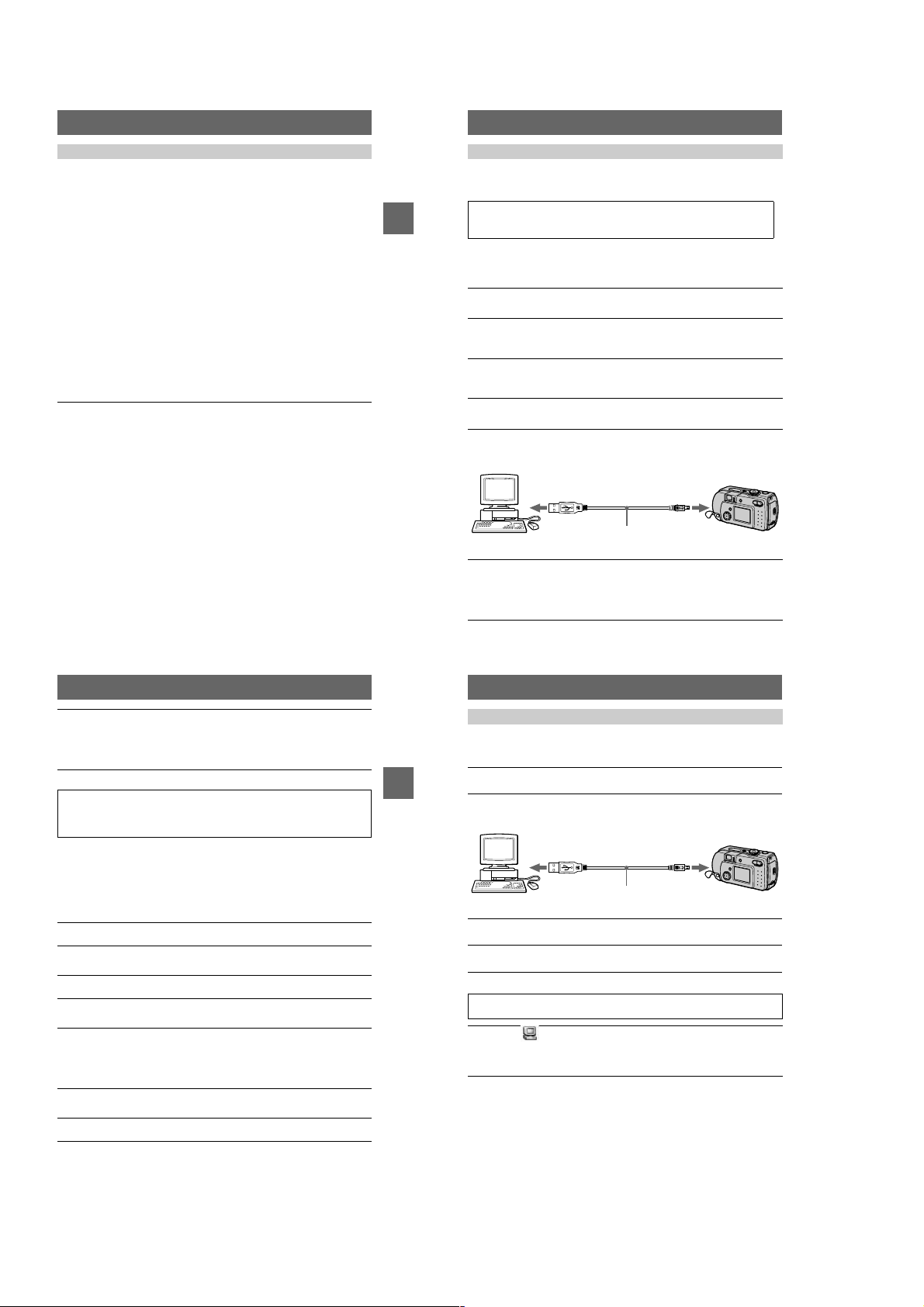
Connect the USB jack (mini-B) on your camera with the USB
5
connector on your personal computer using the supplied USB
cable.
USB cable
to the USB ja ck
(mini-B)
Push the
connector in as
far as it will go.
to the USB connector
Personal computer
Insert a “Memory Stick” into your camera, connect the AC power
6
adaptor and turn on your camera.
“USB MODE” appears on the LCD screen of your camera and the camer a is set
to communication standby mode. Your personal computer recognizes the
camera, and the Windows Add Hardware Wizard starts.
31
Follow the on-screen messages to have the Add Hardware Wizard
7
recognize the hardware.
The Add Hardware Wizard starts twice because two different USB dr ivers are
to be installed. Be sure to allo w the i nstallatio n to complet e without inte rrupting
it.
Notes
•
Do not connect the USB cable bef or e the USB driver installation is completed in step 4.
•
In step 7, make sure that a “Memory Stick” is inserted into your camera before installing the
USB driver. Otherwise, you will be unable to install the USB driver.
For Macintosh users
• When using MacO S9.1
It is not necessary to install the USB driver. The Macintosh recognizes the camera as
a drive simply by connecting it to the Macintosh with the USB cable.
• When using MacOS8.5.1/8.6/9.0
Follow the procedures below to install the driver.
Turn on your personal computer and allow the Mac OS to load.
1
Insert the supplied CD-ROM in the CD-ROM drive of your personal
2
computer.
Double-click the CD-ROM drive icon to open the window.
3
Double-click the icon of the hard disk containing the OS to open
4
the window.
Move the following two files from the window opened in step 3 to
5
the “System Folder” icon in the window opened in step 4 (drag
and drop) .
•
Sony USB Driver
•
Sony USB Shim
When “Put these items into the Ex te nsions folder?” appears, click
6
“OK.”
Restart your personal computer.
7
32
Viewing images
When viewing moving images on a Windows system, RealPlayer, Windows Media
Player or other moving ima ge playba ck applic ations must be in stalled . When v ie wing
moving images on a Macintosh system, QuickTime3.0 or later must be installed.
Turn on the power of your personal computer and allow Windows
1
or Mac OS to load.
BB
B
B
Playback
Connect the USB jack (mini-B) on the camera with the USB
2
connector on your personal computer using the supplied USB
cable.
to the USB connector
Personal computer
Insert a “Memory Stick” into your camera, and connect the AC
3
power adaptor to your camera and then to a wall outlet (mai ns) .
Turn on the power of your camera.
4
“USB MODE” appears on the LCD screen of th e camera.
USB cable
to the USB ja ck
(mini-B)
Push the
connector in as
far as it will go.
For Windows 98/98SE/Me and Windows 2000 users
Open “ My Computer” on Windows and double click the newly
5
recognized drive. (Example: “Removable Disk (E:)”)
The folders inside the “Memory Stick ” are displayed.
If the drive is not recognized, see “Troubleshooting” on page 75.
33
34
1-8
Page 15
Select and double-click the desired image file from the folder.
6
For the detailed folder and file name, see “Image file storage destinations a nd
image files” on page 37.
Desired file type Double-click in this order
Still image “Dcim” foldert“100msdcf” foldertImage file
Moving image* “Mssony” foldert“Moml0001” foldertImage file*
Clip Motion
image
E-mail image
TIFF image
(uncompressed)
Copying a file to the hard disk of your personal computer befor e v iewing it is
∗
recommended. If you play back the file directly from the “Memory Stick”, the image
may break off.
“Dcim” foldert“100msdcf” foldertImage file
“Mssony” folder t“Imcif100” fold ertImage file
For Macintosh users
Follow the procedure 1 – 4 on page 34.
Double click the newly recognized icon on the desktop.
5
The folders inside the “Memory Stick” are displayed.
Select and double-click the desired image file from the folder.
6
Notes on using your personal computer
“Memory Stick”
•
Operation is not guaranteed if you are using a “Memory St ic k” that was formatted with a
personal computer, or if you used a personal computer to format the “Memory Stick” in your
camera through a USB connection.
•
Do not optimize the “Memory Stick” on a Windows machine. This will shorte n the “Memory
Stick” life.
•
Do not compress the data on the “Memory Stick.” Compressed files cannot be played back on
your camera.
For Windows Me and Windows 2000 u sers
The following procedures are recommended when disconnecting the USB cable from
your personal computer or ejecting the “Memory Stick” from the camera while it is
connected to your pers onal computer.
1
Stop the drive by clicking on the “Unplug/Eject” icon in the task tray.
2
When the message appear s confirming the safe removal of the hardware,
BB
B
B
Playback
disconnect the USB cable or eject the “Memory Stick”.
Software
•
Depending on your application software, the file size may increase when you open a still image
file.
•
When you load an image modified using the supplied retouch software from your personal
computer to the camera or when you directly modify the image on the camera, the image
format will differ so the “FILE ERROR” message may appear and you may be unable to ope n
the file.
•
Depending on your application software, only the first frame of the Clip Mot ion file may be
played back.
Communications with your personal computer (for Windows
only)
Communications between your camera and your personal computer may not recover after
recovering from Suspend, Resume, or Sleep.
35
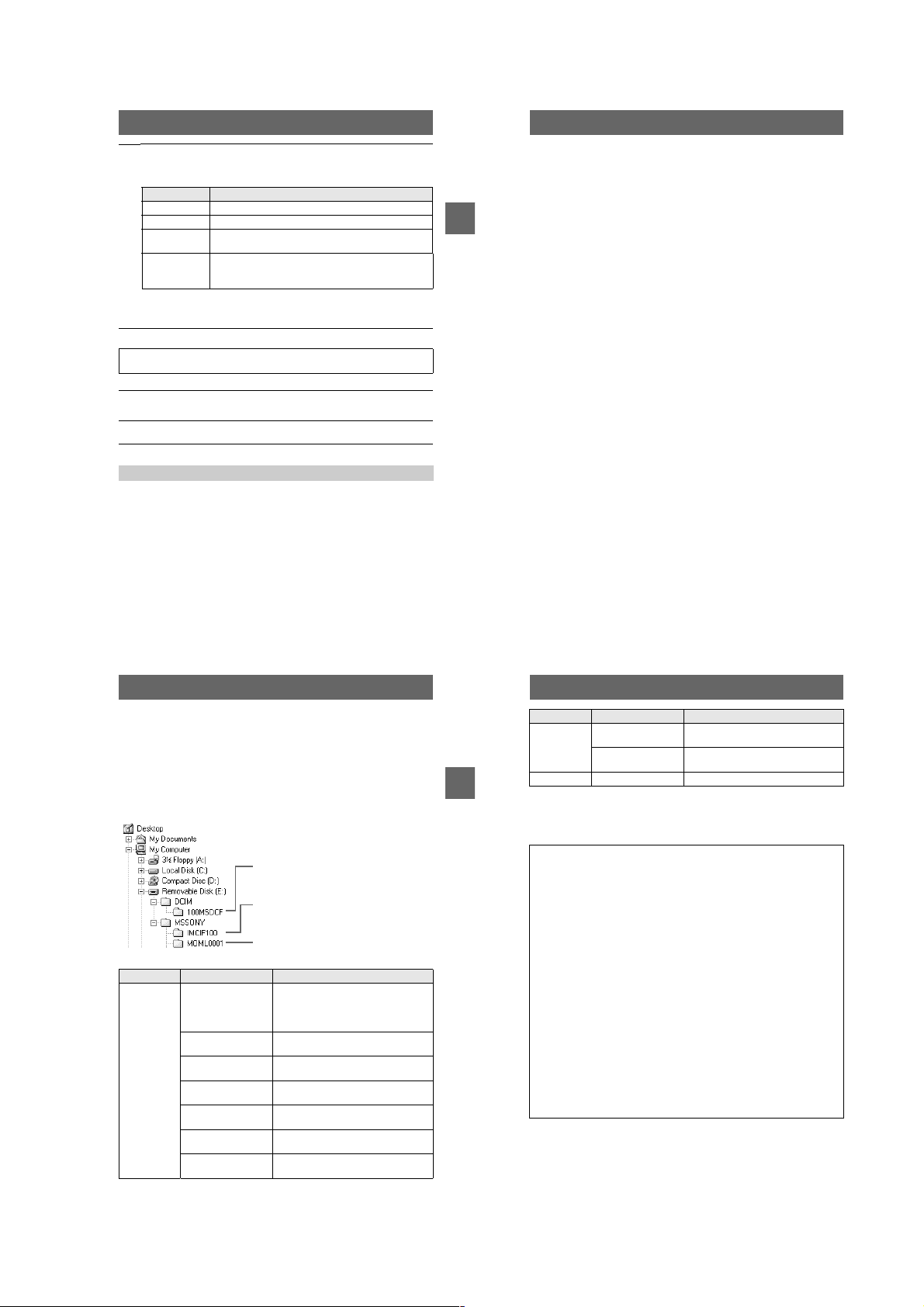
Image file storage destinations and
image files
Image files recorded with y our camera are grouped in fold ers by recording mode.
The meanings of the file names are as follows.
within the range from 0001 to 9999.
For Windows Me users (The drive recognizing the camer a is
“E.”)
Folder containing still im age, TEXT mode image
and Clip Motion image data
Folder containing E-MAIL mo de and TIFF mode
image data
Folder containing movi ng image data
Folder File Meaning
100MSDCF DSC0
CLP0
CLP0
MBL0
MBL0
TXT0
TXT0
.JPG•Still image file recorded normally
ssss
ssss
ssss
ssss
ssss
ssss
ssss
•
.GIF•Clip Motion file recorded in NORMAL
.THM•Index image file of Clip Motion file
.GIF•Clip Motion file recorded in MOBILE
.THM•Index image file of Clip Motion file
.GIF•Still image file recorded in TEXT mode
.THM•Index image file of still image file
stands for any number
ssss
Still image file recorded in
– E-MAIL mode (page 48)
– TIFF mode (page 50)
mode (page51)
recorded in NORMA L m ode
mode (page51)
recorded in MOBILE m ode
(page 49)
recorded in TEXT mode
36
Folder File Meaning
IMCIF100 DSC0
DSC0
MOML0001 MOV0
BB
B
B
Playback
The numerical portions of the following files are the same.
– A small-size image file recorded in E-MAIL mode and its corresponding image file
– An uncompressed image file recorded in TIFF mode and its corresponding image file
– An image file recorded in TEXT mode and its corresponding index image file
– An image file recorded with Clip Motion and its corresponding index image file
Tips
The digital still camera saves recorded images as digital data. The format of the
saved data is called as the file format. The formats that can be used with this
camera are as follows:
JPEG format
Most digital still cameras, operating systems of computers, and browser
software adopt this format. This format is able to compress files without
appreciable deterioration. However, if the image is compressed and saved on
repeated occasions, the image will dete riorate. This camera records still images
using the JPEG format for normal recording.
GIF format
Using this format, the image will not deteriorat e ev en if the image is compressed
and saved on repeated occasions. This format limits the number of colors to
256 colors. This camera records still images using the GIF format in Clip
Motion (page51) or TEXT mode (page49).
TIFF format
Stores shooting images without compression, so the image does not deteriorate.
Most of operating systems and applications correspond to this format. This
camera records still images using the TIFF format for the TIFF mode (page 50).
MPEG format
This format is very typical for moving images. This camera records moving
images using the MPEG format.
.JPG•Small-size image file r ecorded in
ssss
ssss
ssss
E-MAIL mode (page 48)
.TIF•Uncompressed image file recorded in
TIFF mode (page 50)
.MPG•Moving image file recorded normally
37
38
1-9
Page 16
Advanced operations
Before performing advanced
operations
This section describes the basic control methods that are frequently used for
“Advanced operations.”
How to use the mode dial
The mode dial switches the function which is used for recording, playback, or
editing. Set the dial as follows before starting to operate your camera.
: To record still images in TWILIGHT mode
: To record still images
: To play back or edit images
: To record moving images or Clip Motion
images
SET UP: To display the setup items (The SET UP
position changes the se ttings of infrequentlyused items.)
How to use the control button
When the menu or setup screen is displayed, the control button is used to select the
buttons, images and menu item s displayed on the LCD screen of your camera and
modify the settings. The operation methods that are frequently used for “Advanced
operations” are described below.
Turning on/off the operation buttons (menu) on the LCD screen
Press MENU to display/
clear the menu on the
LCD screen.
0
EV
Menu
0
WB
ISO
You can perform this operation even when the LCD screen is off.
Setting up the items in the setup or menu
Set the mode dial to SET UP so that the
Before performing advanced operations
1
setup screen appears, or press MENU so
that the menu appears.
When the mode dial is set to SET UP or :
2
1
Press v/V/b/B on the control button to select the item you want to set up.
2
Press the center z on the control button to enter the item.
When the mode dial is set to , , or :
Press v/V/b/B on the control button to select the
setting of the item.
The selected setting is turned to yellow, and the
setup is complete.
CAMERA
MOVING IMAGE:
DATE/TIME:
DIGITAL ZOOM:
RED EYE REDUCTION:
AF ILLUMINATOR:
SELECT
MPEG MOVIE
OFF
ON
OFF
ON
00
200
100
O
Menu settings
Menu items that can be modified differ depending on the positions of th e mode dial.
The LCD screen shows only the items you can operate at the mo m ent. Factory
settings are indicated w ith x.
When the mode dial is set to /
Item Setting Description
EV +2.0EV to
9
(FOCUS)
WB
(WHITE
BAL)
(SPOT
METER)
ISO 400
(IMAGE
SIZE)
(P. QUALITY)
–2.0EV
(infinite)
∞
7.0 m
3.0 m
1.0 m
0.5 m
AUTO
x
HOLD
AUTO
x
IN DOOR
OUT DOOR
ON
OFF
x
200
100
AUTO
x
1600×1200
x
(DSC-P50)
1280×960
x
(DSC-P30)
1600 (3:2)
(DSC-P50)
1280(3:2)
(DSC-P30)
1024×768
640×480
FINE Records still images in the fine image quality
x
STANDARD Records still images in the standard image
Adjust the exposure value (page 53).
Sets the distance to the subject (page 52).
Sets the white balance (pag e 5 4) .
Measures the brightness of the spot to be
recorded (page 57).
Selects the ISO film speed. When recording
under dark situations or recording a fast-moving
subject, use a high-number setting. When you
record high-quality images, use a low-number
setting (except when the mode dial i s se t to ).
Selects the image size when recording still
images (page 45).
mode.
quality mode.
39
40
Item Setting Description
MODE
(REC
MODE)
±
(FLASH
LEVEL)
PFX
(P. EFFECT)
Before performing advanced operations
(
SHARPNESS
When the mode dial is set to (MOVING IMAGE is set to
MPEG MOVIE in the setup se ttings.)
EV +2.0EV to
9
(FOCUS)
WB
(WHITE
BAL)
(SPOT
METER)
TIFF Records a TIFF (uncompr essed) file in addition
to the JPEG file (page 50).
TEXT Records a GIF file in black-a nd-white (page 49).
E-MAIL Records a small-size (320×24 0) JPEG file in
NORMAL Records an image using the normal recording
x
addition to the selected image size (page 48).
mode.
HIGH Makes the fl as h level higher than normal.
NORMAL Normal setting.
x
LOW Makes the flash level lower than normal.
x
)+2+1
x
SOLARIZE
B&W
SEPIA
NEG.ART
OFF
0
–1
–2
Sets the image special effects (page 55).
Adjusts the sharpnes s of the image.
The indicator appears (e xcept when the
setting is 0).
Item Setting Description
–2.0EV
(infinite)
∞
7.0 m
3.0 m
1.0 m
0.5 m
AUTO
x
HOLD
AUTO
x
IN DOOR
OUT DOOR
ON
OFF
x
Adjust the exposure value (page 53).
Sets the distance to the subject (page 52).
Sets the white balance (page 54).
Measures the brightness of the spot to be
recorded (page57).
41
42
1-10
Page 17
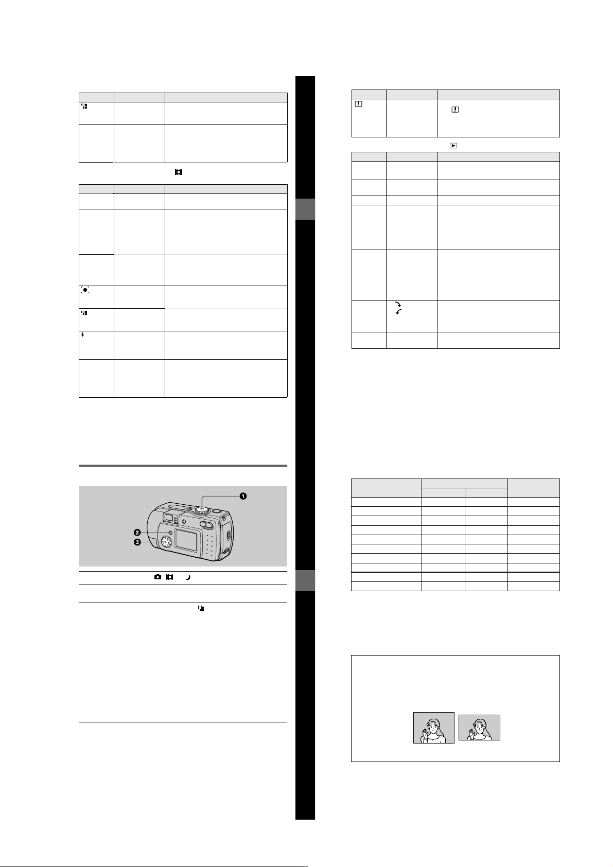
Item Setting Description
(IMAGE
SIZE)
PFX
(P. EFFECT)
When the mode dial is set to (MOVING IMAGE is set to CLIP
MOTION in the setup settings.)
EV +2.0EV to
9
(FOCUS)
WB
(WHITE
BAL)
(SPOT
METER)
(IMAGE
SIZE)
±
(FLASH
LEVEL)
PFX
(P. EFFECT)
320×240
160×112
x
SOLARIZE
B&W
SEPIA
NEG.ART
OFF
x
Item Setting Description
–2.0EV
(infinite)
∞
7.0 m
3.0 m
1.0 m
0.5 m
AUTO
x
HOLD
AUTO
x
IN DOOR
OUT DOOR
ON
OFF
x
NORMAL
x
MOBILE
HIGH Makes the flash level higher than normal.
NORMAL Normal setting.
x
LOW Makes the flash level lower than norm al .
SOLARIZE
B&W
SEPIA
NEG.ART
OFF
x
Selects the MPEG image s iz e w hen recording
moving images (page 45).
Sets the image special effects (page 55).
Adjust the exposure value (page 53).
Sets the distance to the subject (page 52).
Sets the white balance (page 5 4).
Measures the brightness of the spot to be
recorded (page 57).
Selects the Clip Motion image size (page 45,
51).
Sets the image special effects (page 55).
Item Setting Description
(
SHARPNESS
When the mode dial is set to
DELETE OK Deletes the displayed image (page 62).
PROTECT – Protect s images against accidental era sure
PRINT – Marks the print mark on still images (page 66).
SLIDE*
Before performing advanced operations
RESIZE* 1600×1200
ROTA TE*
DIVIDE OK
Only in single-image mode.
∗
+2
)
+1
0
x
–1
–2
Item Setting Description
CANCEL Cancels deleting of the image.
INTERVAL
REPEAT
START Starts the slide show.
CANCEL Cancels the slide show.
(DSC-P50)
1280×960
(DSC-P30)
1024×768
640×480
CANCEL
OK
CANCEL
CANCEL
Adjusts the sharpnes s of the image.
The indicator appears (except w hen the
setting is 0).
(page 63).
Sets the slide show interval.
3 sec/5 sec/10 sec/30 sec/1 m i n
x
ON/OFF
x
Changes the recorded image size (page65).
Rotates the still image (page 61).
Divides an moving image (page 67).
Setting the image size (IMAGE SIZE)
Set the mode dial to , or
1
Press MENU.
2
The menu appears.
Select the desired image size from [ ] (IMAGE SIZE) and press
3
.
v/V
Still image sizes:
DSC-P50
1600×1200, 1600 (3:2 )*, 1024×768, 640×480
DSC-P30
1280×960, 1280(3:2)* , 1024×768, 640×480
The image is recorded in the ratio of three to two to fit the printing paper size. Using this
∗
image size, the margin of an image is not printed out. However, the slight amount of the
upper and lower black portions are displayed on the LCD screen.
Moving image (MPEG movie) sizes:
320×240, 160×112
Clip Motion sizes:
NORMAL (160×120), MOBILE (80×72)
.
43
44
The number of images* or the time** that you can record on a “Memory
Stick” (4 MB)
Image size
1600×1200 (DSC-P50) Approx. 7 Approx. 3 –
1600 (3:2) (DSC-P50) Approx. 7 A pprox. 3 –
1280×960 (DSC-P30) Approx. 11 Approx. 6 –
1280 (3:2) (DSC-P30) Appr ox. 11 Approx. 6 –
1024×768 Approx. 16 Approx. 10 –
640×480 Approx. 57 Approx. 23 –
320×240 ––
160×112 ––
MOBILE (80×72) ––Approx. 200
Before performing advanced operations
NORMAL (160×120)*** ––Approx. 20
When MODE (REC MODE) is set to NORMAL.
∗
The maximum recording time in continuous rec o rd ing
∗∗
When recording 10 frames per Clip Motion file.
∗∗∗
Remaining num ber of reco rdable images (p age 85)
The remaining number of recordable im ages i s a guide lin e for when MODE (R EC MODE) is set
to NORMAL. The actual number of remaining images may differ depending on the recording
conditions.
Tips
The size of the image is indicated by the pixel unit. The higher the number of pixels, the more
information is included. So , a n image that is saved using a large number of pixels is suitable
for a large-format print and one that is saved using a smaller number of pixels is suitable for
attaching to an E-mail. Normally, an image is recorded in the ratio of four to three to fit the
monitor ratio. This ca mera can also record the image in the ratio of three t o two to
accommodate the most common printing paper size. This is the same ratio as the one used in
photo-developing shops.
Quality
STANDARD FINE
Moving image
Approx. 40 sec.
Approx. 160 sec.
45
1600×1200 (4:3) 1600 (3: 2)
46
1-11
Page 18
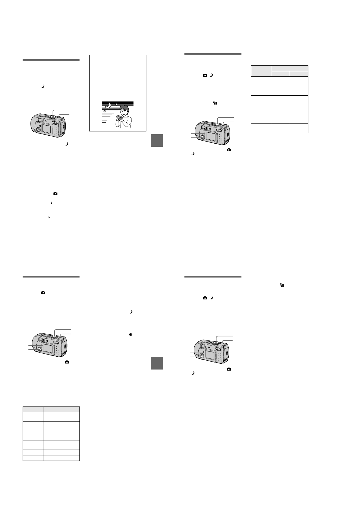
Various recording
B
Records images
according to shooting
conditions (TWILIGHT
mode)
Mode dial:
This camera has a preset TWILIGHT
mode. This m o de is suitable for the
night scene.
1
2
1
Set the mode dial to .
Allows you to record bright
subjects in dark places without
losing the dark atmosphere of the
surroundings. The shutter speed
becomes slower, so we
recommend that you use a tri pod
to prevent shaking.
2
Record the image.
To cancel the TWILIGHT
mode
Set the mode dial to .
Notes
•
Set the forced flash whe n you use the
flash in the TWILIGHT mode.
•
When using the TWILIGHT mode, the AF
illuminator (page 25) emits when the flash
mode is set to the forced flash mode.
•
You cannot record moving images in the
TWILIGHT mode.
Tips
Under normal recording conditions, the
camera automatically makes various
adjustments, such as those for the focus,
iris, exposure, and white balance, as it
shoots. However, you may not be able to
carry out your desired shooting
depending on shooting conditions. The
TWILIGHT mode provides you with
near-optimum adjustments to suit your
shooting situation.
BB
B
B
Various recording
Recording still
images for e-mail
(E-MAIL)
Mode dial: /
In the E-MAIL mode, a small-size
image which is suitable for e-mail
transmission is also recorded at the
same time as recording a normal still
image. (The size of the normal still
image is set using [ ] (IMAGE
SIZE) in the menu settings (page 45).)
1
4
2
3
1
Set the mode dial to or
.
2
Press MENU.
The menu appears.
3
Select [MODE] (REC MODE)
with b/B, [E-MAIL] with v/V.
4
Record the image.
The number of images that you can
record on a “Memory Stick” (4 MB)
in E-MAIL mode
Image size
1600×1200
(DSC-P50)
1600 (3:2)
(DSC-P50)
1280×960
(DSC-P30)
1280 (3:2)
(DSC-P30)
1024×768
640×480
Remaining number of recordable
images (page 85)
The actual number of remaining images
may differ depending on the recording
conditions.
To return to normal
recording mode
Select [NORMAL] with v/V in step 3.
Quality
STD FINE
Approx. 7 Approx. 3
Approx. 7 Approx. 3
Approx. 10Approx.
Approx. 10Approx.
Approx. 15Approx.
Approx. 46Approx.
5
5
9
21
Recording text
documents (TEXT)
Mode dial:
The TEXT mode is suitable for
recording a document to emphasize its
character by the black and white
colors. The LCD screen also turns to
black and white, and the i m age is
recorded in the GIF format.
1
4
2
3
1
Set the mode dial to .
2
Press MENU.
The menu appears.
3
Select [MODE] (REC MODE)
with b/B, [TEXT] with v/V.
4
Record the image.
The number of images that you can
record on a “Memory Stick” (4 MB)
in TEXT mode*
Image size Number of images
1600×1200
(DSC-P50)
1600 (3:2)
(DSC-P50)
1280×960
(DSC-P30)
1280 (3:2)
(DSC-P30)
1024×768 Minimum 26
640×480 Minimum 59
The maximum number of recordable
∗
images depends on the document
condition, such as the amount of text
portions.
Minimum 12
Minimum 13
Minimum 18
Minimum 20
47
To return to normal
recording mode
Select [NORMAL] with v/V in step 3.
Notes
•
If the subject is not evenly illuminated, you
may be unable to record a clear image.
•
Writing and reading data take more time
than normal recording.
•
When the mode dial is set to , images
can be recorded, but the image may be
bleached out or may be turned black.
•
Remaining number of recordable images is
not displayed.
•
The number of recordable images is the
same regardless of whether [ ]
(P. QUALITY) is set to STANDARD or
FINE.
49
BB
B
B
Various recording
48
Recording still images
as uncompressed
files (TIFF)
Mode dial: /
Records the images without
compression, so the image does not
deteriorate. Image s recorded in this
mode are suitable for printing with a
high-quality image. The JP EG
(compressed) format image is also
recorded with the TIFF format image.
1
4
2
3
1
Set the mode dial to or
.
2
Press MENU.
The menu appears.
3
Select [MODE] (REC MODE)
with b/B, [TIFF] with v/V.
4
Record the image.
The number of images that you
can record on a “Memory Stick”
(8 MB) in TIFF mode is approx. 1.
To return to normal
recording mode
Select [NORMAL] with v/V in step 3.
50
Notes
•
JPEG images are recorded in the image
size selected by the [ ] (IMAGE SIZE)
menu (page 45). TIFF images are recorded
in [1600×1200] (DSC-P50) or [1280×960]
(DSC-P30) size other than when [1600
(3:2)] (DSC-P50) or [1280 (3:2)]
(DSC-P30) is selected.
•
Writing data takes more time than in
normal recording.
•
The supplied “Memory Stick” (4 MB)
does not have sufficient capacity to record
uncompressed images.
1-12
Page 19

Creating Clip Motion
Files
Mode dial:
Clip Motion is an animation function
that plays back still images in
succession. The images are stored in
GIF format, which is convenient for
creating home pages or attaching
images to an e-mail.
1,3
6,7
4
2,5,8
1
Set the mode dial to SET UP.
The setup screen appe ar s.
2
Select [ ] (CAMERA) with
, [MOVING IMAGE] with
v/V
, [CLIP MOTION] with
B/v/V
, then press z.
v/V
3
Set the mode dial to .
4
Press MENU.
The menu appears.
5
Select [ ] (IMAGE SIZE)
with b/B, the desired mode
with v/V.
NORMAL (160×120)
Clip Motion of up to 10 frames can
be recorded. This is suitable for
use on home pages, etc.
MOBILE (80×72)
Clip Motion of up to 2 frames can
be recorded. This is suitable for
use with portable data terminals.
6
Record the image for the fir st
frame.
60
min
MAKING "CLIP MOTION"
Before carrying out step 8, the
images are temporarily stored in
memory. These images are not
recorded on the “Memory Stick”,
yet.
7
Record the image f or the ne xt
frame.
Image recording can be repeated
up to the maximum number of
recordable frames.
8
Press z.
All the frame images are recorded
on the “Memory Stick”.
To delete some or all the
frame images while making
a Clip Motion recording
1
Press the control button b (7) in
step 6 or 7.
The recorded frame images are
played back in turn and stop at the
last image.
2
Press MENU, and select [DELETE
LAST] or [DELETE ALL], then
press z.
3
Select [OK], then press z.
When [DELETE LAST] is selected
in step 2, each time you repeat
step 3, the recorded frame is
deleted from the newest one.
BB
B
B
Various recording
The number of Clip Motion frames
that you can record on a “Memory
Stick” (4 MB)
Image size
NORMAL (160×120)
MOBILE (80×72) Approx. 200
When recording 10 frames per Clip
∗
Motion file
Notes
•
You cannot change the image size partway
through a Clip Motion recording.
•
Reading and writing data take more time
than normal image recording.
•
Due to the limitations of th e G IF format,
the number of colors for Clip Motion
images is reduced to 256 colors or less.
Therefore, the picture quality may
deteriorate for some images.
•
The file size is redu ced in MOBILE mode,
so the picture quality deteriorates.
•
GIF files not created on this camer a ma y
not be displayed correctly.
•
All the frame images are immediately
recorded on the “Memory Stick” if the
mode dial is switched or the power is
turned off.
Number of
images
Approx. 20*
Setting the distance
to the subject
Mode dial: /
Normally the focus is automatically
adjusted. This function is useful when
the auto focus does not work well such
as in dark places.
/
1
2
3
1
Set the mode dial to ,
or .
2
Press MENU.
The menu appears.
3
Select [9] (FOCUS) with
, the desired distance
b/B
setting with v/V.
You can select from the fol l owin g
6 focus settings:
AUTO, 0.5 m (1 3/4 feet), 1.0 m
(3 1/4 feet), 3.0 m (9 3/4 feet),
7.0m (23feet), ∞ (infinite).
To reactivate auto focusing
Select [AUTO] with v/V in step 3.
Notes
•
Focal point information may not
completely show the correct distance. Use
the information as a guide.
•
If you shoot a subject within 0.5 m
(1 3/4 feet) while the zoom is set to th e T
side, you cannot get a clear focus. In such
cases, the focal point information flas h es .
Press the zoom W button until the
indicator stops flashing.
Recording images in
macro
Mode dial: / /
The macro recording is used when
zooming up a little subject, such as
flowers, insects.
1
2
3
1
Set the mode dial to ,
or .
2
Clear the menu, and press
the control button B ().
The (m acro) indicator appears
on the LCD screen.
You can record a subject as cl ose
as about 3 cm (1 3/16 inches) from
the lens surface with the zo om set
all the way to the W side, or about
80 cm (31 1/2 inches) wi th the
zoom set all the way to the T side.
To return to normal
recordin g mo de
Press the control button B ( ) again.
The indicator disappears.
Note
When recording images in macro, use the
LCD screen. If you record using the finder,
the range visible in the finder may differ
from the actual recording range.
51
Adjusting the
exposure
(EXPOSURE)
Mode dial: / /
Adjusts the exposure v alue wh ich is set
in the automatic adjustment.
1
2
3
1
Set the mode dial to ,
.
or
2
Press MENU.
The menu appears.
3
Select [ ] (EV) with b/B, the
desired exposure value with
.
v/V
Adjust the exposure value while
checking the brightness of the
background.
Y ou can select values ranging from
+2.0 EV to –2.0 EV in steps of 1/3
EV.
Note
If a subject is under extremely bright or dark
situations, or the flash is use d, the exposure
adjustment may not be effective.
53
BB
B
B
Various recording
52
Tips
Normally, the camera automatically
adjusts the exposure. If the color of the
image is too dark or bright as illustrated
below, we recommend that you adjust the
exposure manually. When recording a
backlighted subject or a subject in the
snow, set it toward +, and when recording
a dark subject with fully displayed on the
LCD screen, set it toward –.
Set the exposure
toward +
Set the exposure
–
toward
54
Adjusting the white
balance (WHITE
BALANCE)
Mode dial: / /
Normally, the white balance is
automatically adjusted (AUTO). When
you record with the shooting condition
fixed or under the specific lighting
condition, you can manually adjust the
white balance.
1
2
3
1
Set the mode dial to ,
or .
2
Press MENU.
The menu appears.
3
Select [WB] (WHITE BAL)
with b/B, the desired setting
with v/V.
HOLD
Recording a single-colored subject
or background
AUTO (No indicator)
Adjusts the white balance
automatically
Under fluorescent lighting
IN DOOR (n)
•
Places where the lighting
condition changes quickly
•
Under bright lighting such as
photography studios
•
Under sodium or mercury lamps
OUT DOOR ( )
Recording a sunrise/sunse t, night
scene, neon signs, or fireworks
1-13
Page 20
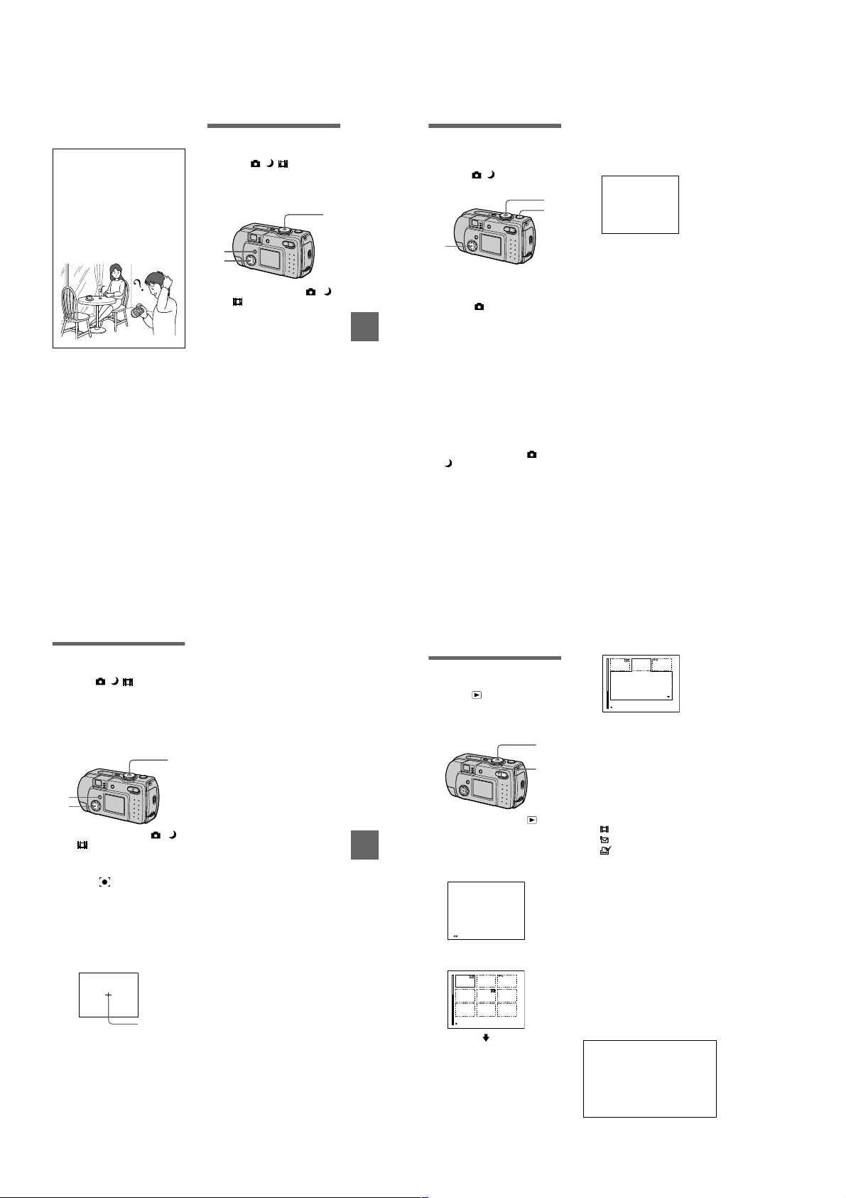
To reactivate auto adjustment
Select [AUTO] with v/V in step 3.
Tips
The image is susceptible to lighting
conditions. The image looks blue under
sunlight in the summer, and looks red
under mercury lamps. Human eyes can
resolve these problems. However, the
camera cannot resolve the pro b le m
without making adjustments. Normally,
the camera adjusts it automatically, but, if
the image appears in stran ge colors, we
recommend that you change the white
balance mode.
Enjoying picture
effects (P. EFFECT)
Mode dial: / /
You can digitally process images to
obtain special effect.
2
3
1
Set the mode dial to ,
or .
2
Press MENU.
The menu appears.
3
Select [PFX] (P . EFFECT) with
, the desired mode with
b/B
.
v/V
SOLARIZE
The light contrast is clearer and the
picture looks like an illustration.
B&W
The picture is mono chrome (black
and white).
SEPIA
The picture is sepia-toned like a n
old photograph.
NEG.ART
The color and brightness of the
picture are reversed as in a
negative.
OFF
Does not use the picture effect
function.
To cancel picture effect
Select [OFF] with v/V in step 3.
5
Record the image.
Recording the date
and time on the still
image (DATE/TIME)
Mode dial: /
1,4
1
5
2,3
1
Set the mode dial to SET UP.
The setup screen appears.
2
Select [ ] (CAMERA) with
, [DATE/TIME] with B/v/V,
v/V
then press B.
3
BB
B
B
Various recording
Select the date and time
setting with v/V, then press
.
z
DAY & TIME
Imposes the date, hour, and
minute.
DATE
Imposes the year, month, and day.
OFF
Does not impose the date and time.
4
Set the mode dial to or
.
The date and time do not appear on
the LCD screen during shooting.
These appear during play ba ck
only.
2001
Notes
•
If you select [DATE] in step 3, the date is
imposed onto the image in the order
selected with “Setting the date and time”
(page 15).
•
The date and time are not superimposed
onto moving images or Clip Motion
images.
Using the spot lightmetering function
Mode dial: / /
Use this function when there is
backlight or when there is strong
contrast between the subject and the
background, etc. Position the point you
want to record on the spot lightmetering cross hair.
1
2
3
1
Set the mode dial to ,
or .
2
Press MENU.
The menu appears.
3
Select [ ] (SPOT METER)
with b/B, [ON] with v/V.
Position the point you want to
record at the spot light-metering
cross hair.
Record the picture wh en the
automatic adjustment has been
completed.
LCD screen
Spot lightmetering
cross hair
To cancel the spot lightmetering function
Select [OFF] with v/V in step 3.
55
57
BB
B
B
Various recording
56
Various playback
B
Playing back three or
nine images at once
Mode dial:
Y ou can display mult iple images on the
LCD screen at one time using the
zoom buttons.
1
2
1
Set the mode dial to .
2
Press the zoom W button
repeatedly.
The LCD screen display changes
as follows:
•
Single (single-image) scree n
10:30
PM
2001 7 4100-0001
FILE BACK/NEXT
•
Index (nine-image ) screen
CLIP TEXT
SINGLE DISPLAY
58
•
Triple-image screen
APERTURE VALUE :
F2.2
SHUTTER SPEED :
1/125
+0.0
EXPOSURE VALUE :
CLIP TEXT
10:30
PM
2001 7 4100-0005
SINGLE DISPLAY
The image indicated by the yellow
frame in the index screen is
displayed in the middle of the
triple-image screen with the
recording informati on. To display
the other information, press the
control button v/V.
The following marks ar e displa yed
on each image according to th e
image type and settings.
: Moving image file
: E-mail file
: Print mark
: Protect mark
-
TEXT: TEXT file
TIFF: TIFF file
CLIP: Clip Motion file
(No mark): Normal recording (no
settings)
To display the next
(previous) index screen
Press the control button v/V/b/B.
To return to n ormal playback
(single-image)
•
Press the zoom T button repeated ly.
•
Press the control button z.
Note
When viewing an image recorded in Clip
Motion or TEXT mode on the index screen,
the image may appear different from the
actual image.
Tips
When the triple-image screen is displayed,
pressing MENU opens the menu includi ng
[PRINT], [PROTECT], and [DELETE].
For details on these items, see pages 62,
63, or 66. T o cl ose t he menu, press MEN U
again. The menu disappears and the
recording information is indicated.
1-14
Page 21
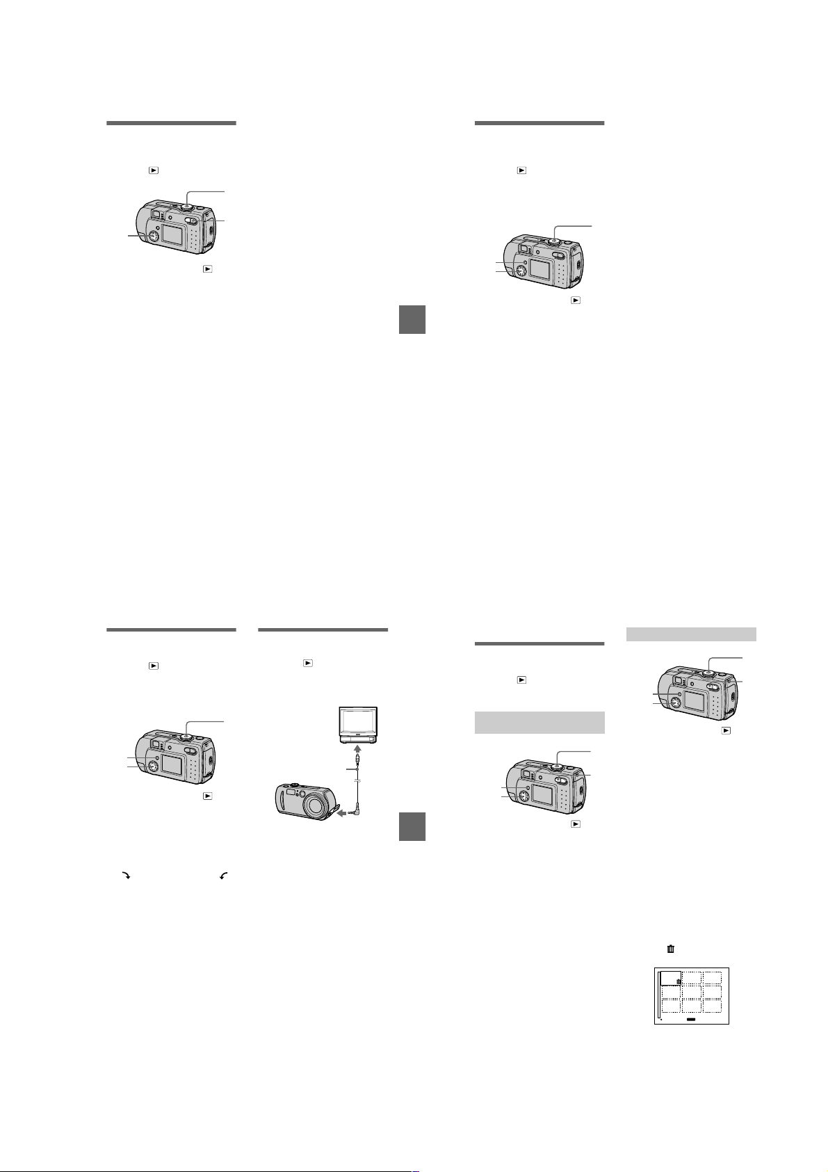
Enlarging a part of
the still image (Zoom
and trimming)
Mode dial:
2,4
1
Set the mode dial to .
2
Display the image to be
enlarged.
3
Zoom in/out the image with
the zoom T/W buttons.
4
Press the control button
repeatedly to select the
desired portion of the image.
: The image moves downward
v
: The image moves upward
V
: The image moves rightward
b
: The image moves leftward
B
To return to the normal size
Press the control button z.
To record an enlarged image
(trimming)
1
Press MENU after zooming.
2
Select [TRIMMING] with B, then
press z.
3
Select the image size with v/V,
then press z.
The image is recorded and the
image on the LCD screen returns
to the normal size after recording.
Notes
•
You cannot zoom moving images.
•
Y ou can zoom images recorded in TEXT
mode, but cannot trim them.
•
Zoom scaling is up to 5× regardless of the
original image size.
•
The quality of enlarged images may be
deteriorated.
•
The original data is left even if you enlarge
1
the image.
•
The enlarged image is recorded as the
newest file.
3
•
If you trim an image, the remaining
“Memory Stick” capacity will be
decreased.
•
If the remaining “Memory Stick” capacity
is not sufficient, you may be unable to trim
an image.
•
You cannot trim to an image of 3:2.
To stop the SLIDE SHOW
Playing back the still
images in order
(SLIDE)
Mode dial:
This function is useful for checking the
recorded images or for presentations,
etc.
2
3,4
1
Set the mode dial to .
2
Press MENU.
BB
B
B
Various playback
The menu appears.
3
Select [SLIDE], then press z.
Set the following items.
INTERVAL
You can select from 1 min ( one
minute), 30 sec (30 second s),
10 sec (10 seconds), 5sec
(5 seconds), or 3sec (3 seconds).
REPEAT
ON: Plays back images in a
continuous loop.
OFF: After all images have been
played back, the slide show end s.
4
Select [START], then press
.
z
The slide show begins.
To cancel the SLIDE SHOW
setting
Select [CANCEL] with v/V in step 3,
then press z.
playback
Press z, select [EXIT] with B, then
press z.
To skip to the next/previous
image during the SLIDE
SHOW
Select b/B at the lower-left on the
LCD screen, then press z.
1
Note
The interval setting time may vary
depending on the image size.
Rotating a still image
(ROTATE)
Mode dial:
You can rotate the image recorded in
portrait orientation and display it in
landscape orient at ion.
2
3,4
1
Set the mode dial to , and
display the i mage to rotate.
2
Press MENU.
The menu appears.
3
Select [ROTATE] with
then press z.
4
Rotate the image clockwise
or counterclockwise ,
select [OK] with v/
press z.
To cancel rotation
Select [CANCEL] with v/V in step 4,
then press z.
Notes
•
You cannot rotate protected or
uncompressed images, or images recorded
in TEXT mode.
•
You may not be able to rotate images
recorded with other equipment.
•
Also, when viewing images on a com puter ,
the image rotation information may not be
reflected depending on the applicati on
software.
,
b/B
then
,
V
Viewing images on a
TV screen
Mode dial:
Before connecting you r ca mera, be
sure to turn off the TV.
Set the TV/VIDEO
1
switch to “VIDEO”.
VIDEO connecting cable
1
Connect the VIDEO
connecting cable to the
VIDEO OUT jack of your
camera and to the video
input jacks of the TV.
2
T urn on the TV and start
playback on your camera.
The playback image appears on
the TV screen.
Notes
•
You cannot use a TV that has an antenna
(aerial) connector only.
•
When viewing a still image on the TV, the
black band may appear around the image.
(supplied)
to VIDEO OUT
jack
59
60
Editing
B
Deleting images
(DELETE)
Mode dial:
You can delete unwant ed files.
In single-image or tripleimage mode
3
2,4,5
1
Set the mode dial to .
2
BB
B
B
Various playback
In single-i m age mode:
Display the image you want to
delete with b/B.
In triple-image mode:
Press the zoom W button twice to
turn to the triple-image mode.
Display the image you want to
delete with b/B.
3
Press MENU.
The menu appears.
4
Select [DELETE] with b/B in
single-image mode, or with
in triple-image mode,
v/V
then press z.
5
Select [OK] with v/V, then
press z.
The image (or the middlepositioned image in triple-image
mode) is deleted.
1
W
In index mode
2
3,4,5
1
Set the mode dial to , then
display the index screen with
the zoom W button.
2
Press MENU.
The menu appears.
3
Select [DELETE] with b/B,
then press z.
4
Select [ALL] or [SELECT]
with b/B, then press z.
5
When you select [ALL]
Select [ENTER] with b/B, then
press z.
All the unprotected images are
deleted.
When you select [SELECT]
1
Select the images to be deleted
with the control button, then
press z.
To cancel, press z again.
Repeat this step to sele ct other
images.
The (delete) indicator
appears on the selected images.
MENU
SET TO NEXT
2
Press MENU.
3
Select [OK] with b/B, then
press z.
1
W
61
62
1-15
Page 22
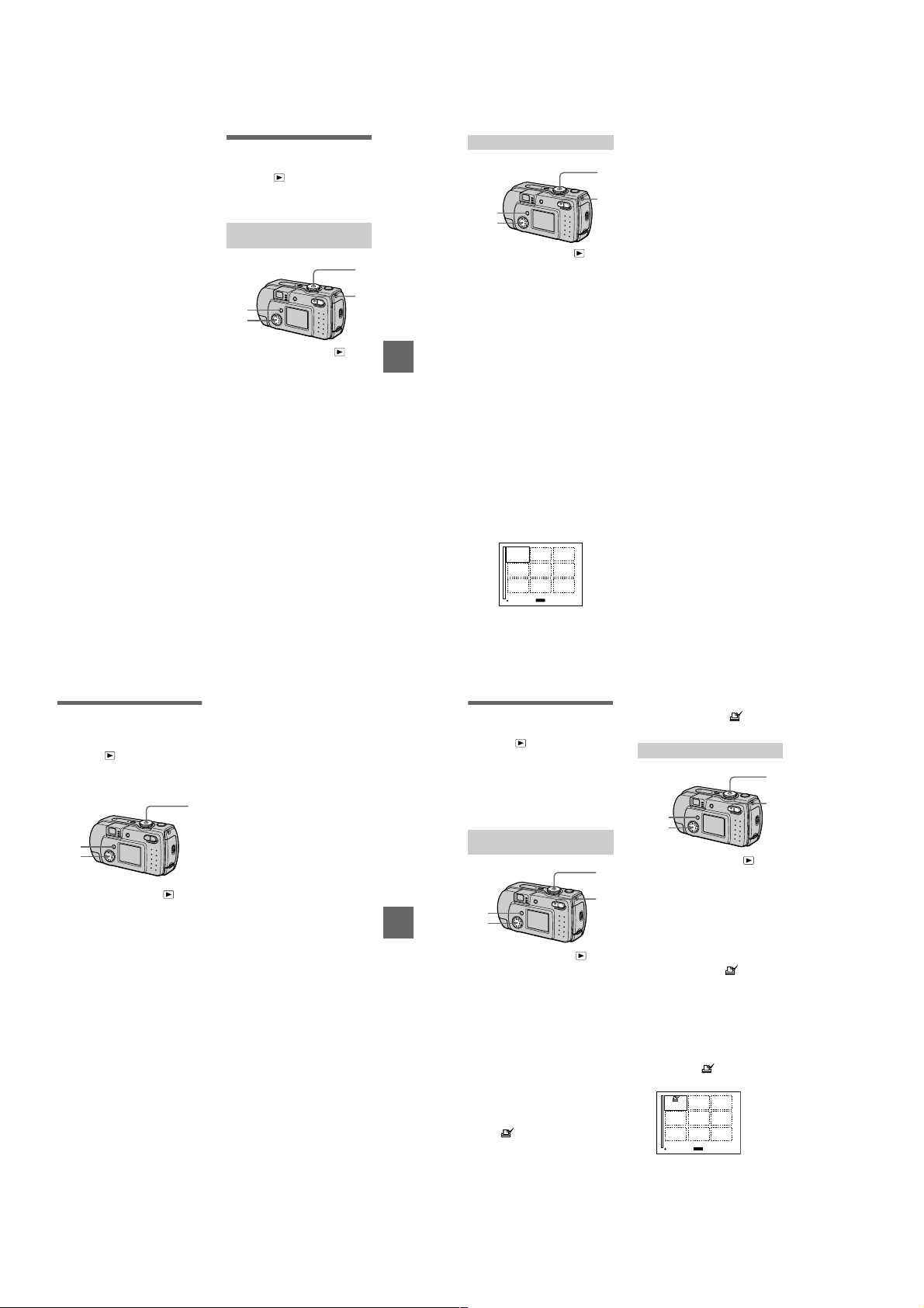
To cancel deleting
Select [CANCEL] with b/B in step 4
or [EXIT] with b/B in step 5, then
press z.
Note
If there are files on the “Memory Stic k” with
names having the same last 4 digits as the
file name of the image to be deleted, the se
files are also deleted at the same time.
Preventing accidental
erasure (PROTECT)
Mode dial:
Protects images again st accidental
erasure.
In single-image or tripleimage mode
1
W
3
2,4
1
Set the mode dial to .
2
In single-i m age mode
Display the image you want to
protect with b/B.
In triple-image mode
Press the zoom W button twice to
turn to the triple-image mode.
Display the image you want to
protect with b/B.
3
Press MENU.
The menu appears.
4
Select [PROTECT] with b/B
in single-image mode, or with
in triple-image mode,
v/V
then press z.
The displayed image (or the
middle-positioned image in tripleimage mode) is protected .
The - indicator appears on the
image.
To release protection
Press z again in step 4. - indicator
disappears.
BB
B
B
Editing
In index mode
2
3,4,5
1
Set the mode dial to , then
display the index screen with
the zoom W button.
2
Press MENU.
The menu appears.
3
Select [PROTECT] with b/B,
then press z.
4
Select [ALL] or [SELECT]
with b/B, then press z.
5
When you select [ALL]
Select [ON] with b/B, then press
.
z
All the images in the “Memory
Stick” are protected.
When you select [SELECT]
The frame of the selected image
turns green.
1
Select the images to be
protected with the control
button, then press z.
To cancel, press z again.
Repeat this step to select other
images.
The - indicator appears on
the selected images.
-
MENU
SET TO NEXT
2
Press MENU.
3
Select [OK] with b/B, then
press z.
To release protection
1
If you selected [ALL] in step 4, select
[OFF] then press z. If you selected
W
[SELECT] in step 4, select the images
to be unprotected with the cont r ol
button. Select [OK] with b/B, then
press z.
To cancel protection
Select [CANCE L ] with b/B in step 4
or [EXIT] with b/B in step 5, then
press z.
Changing the
recorded still image
size (RESIZE)
Mode dial:
You can change the image size of the
recorded image.
2
3,4
1
Set the mode dial to , then
display the i mage of which
you want to change the size.
2
Press MENU.
The menu appears.
3
Select [RESIZE] with b/B,
then press z.
4
Select the desired size with
, then press z.
v/V
DSC-P50:
1600×1200, 1024×768, 640×480
DSC-P30:
1280×960, 1024×768, 640×480
The resized image is recorded.
To cancel changing the size
Select [CANCEL] with v/V in step 4,
then press z.
Notes
•
The original image is retained even after
resizing.
•
Y ou can n ot change the size of images
recorded in TEXT mode, moving images,
uncompressed images, or Clip Motion
images.
•
The resized image is recorded as the
newest file.
•
If you resize an image, the remaining
“Memory Stick” capacity will be
decreased.
1
•
When you change from a small size to a
large size, the picture quality deteriorates.
•
If the remaining “Memory Stick” capacity
is not sufficient, you may not be able to
resize an image.
•
You cannot resize to an image of 3:2.
63
65
BB
B
B
Editing
64
Selecting still images
to print (PRINT)
Mode dial:
You can mark a print mark on still
images recorded with your camera.
This mark is convenient when you
have images printed at a shop that
conforms with the DPOF (Digital Print
Order Format) standard .
.
In single-image or tripleimage mode
1
W
3
2,4
1
Set the mode dial to .
2
In single-i m age mode
Display the image you want to
print with b/B.
In triple-image mode
Press the zoom W button twice to
turn to the triple-image mode.
Display the image you want to
print with b/B.
3
Press MENU.
The menu appears.
4
Select [PRINT] with b/B in
single-image mode, or with
in triple-image mode,
v/V
then press z.
The (print) mark is mark ed on
the displayed image (or the
middle-positioned image in tripleimage mode).
66
To unmark the print mark
Press z again in step 4. mark
disappears.
In index mode
1
W
2,6
3–5,7
1
Set the mode dial to , then
display the index screen with
the zoom W button.
2
Press MENU.
The menu appears.
3
Select [PRINT] with b/B, then
press z.
4
Select [SELECT] with b/B,
then press z.
When marking the mark, you
cannot select [ALL].
The frame of the selected image
turns green.
5
Select the images to be
marked with the control
button, then press z.
To cancel, press z again.
Repeat this step to select other
images. The mark appears on
the selected image.
MENU
SET TO NEXT
6
Press MENU.
The menu appears.
7
Select [OK] with b/B, then
press z.
1-16
Page 23
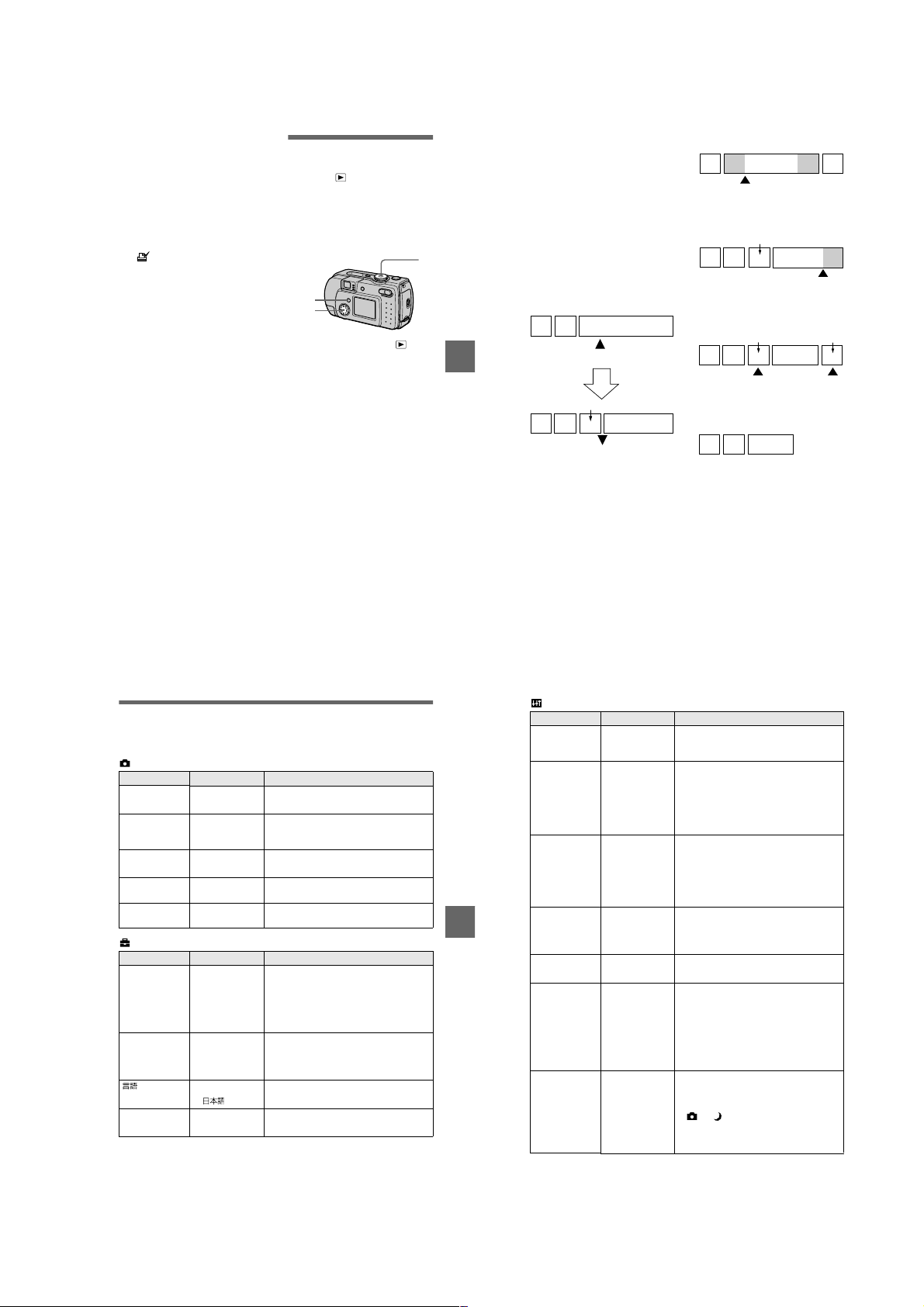
To unmark selected print
marks
Select the images to be unmarked in
step 5 with the control button, then
press z.
To unmark all the print
marks
Select [ALL] with b/B in step 4, then
press z. Select [OFF] with b/B, then
press z.
The marks on all images are
unmarked.
To cancel marking the print
mark
Select [CANCEL] with b/B in step 4
or select [EXIT] with b/B in step 7,
then press z.
Notes
•
You cannot mark moving images, Clip
Motion images or images recorded in
TEXT mode.
•
If you mark an image recorded in TIFF
mode with a print mark, only the
uncompressed image is printed, and the
JPEG image recorded at the same time is
not printed.
•
In E-mail mode, a print mark is marked on
the normal size image that is recorded at
the same time.
Dividing a moving
image file (DIVIDE)
Mode dial:
You can divide moving images
recorded in MPEG MOVIE mo de. This
is convenient when there is not enough
space on a “Memory Stick” or when
attaching moving images to e-mails.
2
3–6
1
Set the mode dial to and
display the moving image
you want to divide.
2
Press MENU.
The menu appears.
3
Select [DIVIDE] with b/B,
then press z, select [OK]
with v/V, then press z.
4
Play the moving image.
If you press z at this time, c,
(frame forward, frame
C
reverse), [CANCEL] and [EXIT]
appear on the screen. If you select
[c, C], you can finely adjust
the divide location using b/B.
If you select [CANCEL], moving
image playback restarts and you
can reselect the divide location.
5
When you have decided the
divide point, select [OK] then
press z.
6
[OK], [CANCEL] and [EXIT]
appear on the screen. Select
[OK], then press z.
The moving image file is divided.
You cannot divide the
following types of files:
•
Clip Motion files
•
Still image files
•
Moving image files that are too short
to divide
The file number changes as
follows when you divide a
file.
<eg.> If you divide the MOV0003.mpg
1
BB
B
B
Editing
file, the divided file numbers become
MOV0004.mpg and MOV0005.mpg,
and MOV0003.mpg is skipped. The
divided files are saved as the latest
files.
1
2
MOV0003.mpg
DIVIDE point
MOV0004.mpg
1 2 MOV0005.mpg
Divided at the designated point
To cancel fi le division
Press [EXIT]. The image playback
screen appears.
To delete unwanted portions
1
Display the portion of the movi ng
image you want to de lete and pres s
MENU.
2
Select [DELETE] with b/B, then
press z.
3
Select [OK] with v/V, then press
.
z
Step 1: Divide the unwanted scene A.
1
MOV0002.mpg
DIVIDE point
Step 2: Divide the unwanted scene B.
MOV0004.mpg
1 MOV0005.mpg3 BA
DIVIDE point
Step 3:Delete the unwanted scenes
A and B.
MOV0004.mpg
13
Step 4:Only the desired scene
remains.
13
MOV0006.mpg
Notes
•
You cannot divide Clip Motion files.
•
You cannot recombine divided files.
•
The original undivided file is not saved.
MOV0007.mpg
AB
MOV0006.mpg
DELETEDELETE
3AB
67
Changing the setup settings (SETUP)
Set the mode dial to SET UP. The setup scre en appears. You can set up the following
items with the control button.
CAMERA
Item Setting Description
MOVING
IMAGE
DATE/TIME DAY & TIME
DIGIT AL ZOOMxON Uses digital zoom (page 23).
RED EYE
REDUCTION
AF
ILLUMINATOR
SETUP 1
Item Setting Description
FORMAT OK Formats a “Memory Stick”.
FILE NUMBERxSERIES Assigns numbers to files in sequence even if
/
LANGUAGE
CLOCK SET OK Sets the date and time (Perform the
MPEG MOVIE Records the MPEG movie (pages 26, 51).
x
CLIP MOTION Records the Clip Motion.
DATE
OFF
x
OFF Does not use digital zoom.
ON
OFF
x
ON
x
OFF
CANCEL Cancels formatting of a “Memory Stick”.
RESET Resets the file numbering each time the
ENGLISH Displays the menu items in English.
x
CANCEL
Sets whethe r to insert the da te and time into
the image (page 56).
Reduces the red-eye phenomenon (page 24).
Uses when it is hard to focus on the subject
under dark situations (page 25).
Note that formatting erases all the
information recorded on a “Memory Stick”,
including even erasure protected images
(page 83).
the “Memory Stick” is changed.
“Memory Stick” is changed.
/JPN Displays the menu items in Japanese.
procedure from step 3 on page 15).
69
BB
B
B
Editing
68
SETUP 2
Item Setting Description
LCD
BRIGHTNESS
LCD
BACKLIGHT
BEEP SHUTTER Turns on the shutter soun d onl y. (The shutter
VIDEO OUT NTSC Sets the video output signal to NTSC mode
USB CONNECT PTP Switches the USB mode (page 30).
POWER SAVExON Set to ON to extend the battery life when
DEMO
Notes on [DATE/TIME]
•
The date and time do not appear on the LCD screen during shooting. The se appea r duri ng
playback.
•
The date and time are not superimposed onto m oving imag e s an d Clip Motion images.
BRIGHT
NORMAL
x
DARK
BRIGHT
NORMAL
x
ON Turns on the beep/ s hutter sound (when you
x
OFF Turns off the beep/shutter sound.
PAL Sets the video output signal to PAL mode
NORMAL
x
OFF When POWER SAVE is set to ON, the time
ON/STBY Displayed only when you use the AC power
x
OFF
Selects the LCD brightness.
This has no effect on the recorded images.
Selects the brightness of the LCD backlight.
Lets you set the brightness of the LCD
backlight to [BR IG H T] or [NORMAL] .
Selecting [BRIGHT] makes the screen
bright and easy to see when using the
camera outdoors or in other bright locations,
but also uses up the battery charge fas te r.
sound is heard when you pr ess the shutter
button.)
press the control button/shu tter button).
(e.g., Japan, the USA) (page 74).
(e.g., Europe) (page74).
operating the camera with batteries.
from when you press the shutter button until
the image is recorded is longer than normal
(pages 11, 88).
The LCD screen turns off while the flash is
charging.
adaptor. [DEMO] is set to [STBY] at the
factory and the demonstration starts about
10 minutes after you have set the mode dial
to or . To cancel the demonstration,
turn off the power. The demonstration will
not start if the MOVING IMAGE setting is
CLIP MOTION.
70
1-17
Page 24
Additional information
Precautions
On cleaning
Cleaning the LCD screen
Wipe the screen surface with a clean i ng
cloth (not supplied) or a LCD cleaning kit
(not supplied) to remove fingerprints, dust,
etc.
Cleaning the camera surface
Clean the camera surface with a soft cloth
slightly moistened with water, then wipe the
surface dry. Do not use any type of solvent
such as thinner, alcohol or benzine as this
may damage the finish or the casing.
After using your camera at the
seashore or other dusty locations
Clean your camera carefully. Otherwise, the
salty air may corrode the metal fittings or
dust may enter the inside of your camera,
causing a malfunction.
Note on operating
temperature
Your camera is designed for use between the
temperatures of 0°C and 40°C (32°F and
104°F). Recording in extremely cold or hot
places that exceed this range is not
recommended.
On moisture condensation
If the camera is brought directly from a cold
to a warm location, or is placed in a very
damp room, moisture may condense inside
or outside the camera. Sho uld t his occur, the
camera will not operate properly.
Moisture condensation occurs
easily when:
•
The camera is brought from a cold location
such as a ski slope into a warmly heated
room.
•
The camera is taken from an airconditioned room or car interior to the hot
outdoors, etc.
How to prevent moisture
condensation
When bringing the camera from a cold place
to a warm place, seal the camera in a plastic
bag and allow it to adapt to conditions at the
new location over a period of time (about an
hour).
If moisture condensation occurs
Turn off the camera and wait about an hour
for the moisture to evaporate. No te that if
you attempt to record with moi s ture
remaining inside the lens, you will be unable
to record clear images.
On AC power adaptor (not
supplied)
•
Unplug the unit from the wall outlet
(mains) when you are not using the unit for
a long time.
•
To disconnect the po wer cord (m ains lead ),
pull it out by the plug. Never pull the
power cord (mains lead) itself.
•
Do not operate the unit with a damaged
cord (mains lead) or if the unit has been
dropped or damaged.
•
Do not bend the power cord (mains lead)
forcibly, or pl ace a hea vy obj ect on it . This
will damage the cord (mai ns le ad) and may
cause fire or electrical shock.
•
Prevent metallic objects from co ming into
contact with the metal parts of the
connecting section. If this happens, a short
may occur and the unit may be damaged.
•
Always keep metal contacts clean.
•
Do not disassemble the unit.
•
Do not apply mechanical shock or drop the
unit.
•
While the unit is in use, particularly during
charging, keep it away from AM receivers
and video equipment. AM reception and
video operation are disturbed.
•
The unit becomes warm during use. This is
not a malfunction.
•
Do not place the unit in locations that are:
—Extremely hot or cold
—Dusty or dirty
—Very humid
—Vibrating
On battery pack (not supplied)
•
Use only the specified charger with the
charging function.
•
To pre ven t accide nt from a short circuit , do
not allow metal objects to come into
contact with the battery termin al s.
•
Keep the battery pack away fro m fire.
•
Never expose the battery pack to
temperatures above 60°C (140°F), such as
in a car parked in the sun or under direct
sunlight.
•
Keep the battery pack dry.
•
Do not expose the battery pack to any
mechanical shock.
•
Do not disassemble nor modify the battery
pack.
•
Install the battery pack to the camera
securely.
•
Charging while some capacity remains
does not affect the original battery
capacity.
If any problem occurs, unplug your camera
and contact your nearest Sony dealer.
On internal rechargeable
button battery
Additional information
This camera has an internal rechargeable
button battery for maintaining the date and
time and other settings regardless of whether
the power is on or off. This rechargeable
button battery is constantly charged as long
as you are using the camera. However, if
you use the camera for only short periods it
discharges gradually, and if you do not use
the camera at all for about one month it
becomes completely discharged. In this
case, be sure to charge this rechargeable
button batte ry before using the camera.
However, even if this rechargeable button
battery is not charged, you can still use the
camera as long as you do not record the date
and time.
Charging method
Connect the camera to a wall outlet (mains)
with the AC power adaptor (not supplied),
or install a charged battery pack or new
alkaline batteries, and leave the camera for
24 hours or more with the POWER button
set to OFF.
On “Memory Sticks”
“Memory Stick” is a new compact, portable
and versatile IC recording medium with a
data capacity that exceeds a floppy disk.
“Memory Stick” is specially designed for
exchanging and sharing digital data among
“Memory Stick” compatible products.
Because it is removable, “Memory Stick”
can also be used for external data storage.
There are two types of “Memory Sticks”:
general “Memory Sticks” and “MagicGate
Memory Sticks” that are equipped with the
MagicGate* copyright protection
technology.
You can use both types of “Memory Stick”
with your camera. However, because your
camera does not support the MagicGate
standards, data recorded with your c amera is
not subject to MagicGate copyright
protection.
MagicGate is copyright protection
∗
technology that uses encryption
technology.
Notes
•
Do not remove the “Memory Stick” while
reading or writing data.
•
Data may be damaged if:
—you remove the “Memory Stick” or turn
off your camera while reading or
writing data.
—you use the “Memory Stick” in a
location subject to the effects of static
electricity or noise.
•
Do not attach any other mater ia l than the
supplied label on th e labeling position .
•
Attach the label so that it does not stick out
from the proper attachment location.
•
When you carry or store the “Memory
Stick,” put it in its supplied case.
•
Do not touch the terminals of a “Memory
Stick” with your hand or a metal object.
•
Do not strike, bend or drop the “Memory
Stick.”
•
Do not disassemble or modify the
“Memory Stick.”
•
Do not allow the “Memory Stick” to get
wet.
“Memory Stick”, , “MagicGate
Memory Stick” and are trademarks of
Sony Corporation.
“MagicGate” and are
trademarks of Sony Corporation.
About “InfoLITHIUM”
battery pack (not
supplied)
What is the “InfoLITHIUM” battery
pack?
The “InfoLITHIUM” battery pack (not
supplied) is a lithium-ion battery pack that
has functions for communicating
information related to operating conditions
between your camera and the AC power
adaptor (not supplied).
The “InfoLITHIUM” battery pack
calculates the power cons umption acco rding
to the operating conditions of your camera,
and displays the remaining battery time in
minutes.
Charging the battery pack
•
Be sure to charge the battery pack before
you start using your camera.
•
We recommend charging the battery pack in
an ambient temperature of between 10°C to
30°C (50°F to 86°F) until the /CHG lamp
goes out, indicating that the battery pack is
fully charged. If you charge the battery
pack outside of this temperature range, you
may not be able to efficiently charge the
battery pack.
•
After charging is completed, disconnect
the AC power adaptor from th e DC IN jack
on your camera or remove the battery
pack.
Effective use of the battery pack
•
Battery performance decreases in lowtemperature surroundings. So, the time that
the battery pack can be used is shorter in
cold places. We recommend the following
to use the battery pack longer:
—Put the battery pack in a p oc k et close to
your body to warm it up, and insert it in
your camera immediately before you
start taking shots.
•
Frequently using the LCD panel or
frequently operating the zoom wears out
the battery pack faster.
•
Be certain to turn the POWER to off when
not taking shots or playing back on your
camera.
•
We recommend having spare batteries
handy for two or three times the expected
shooting time, and make a trial shots
before taking the actual shots.
•
Do not expose the battery pack to water.
The battery pack is not water-resista nt.
Remaining battery time indicator
•
If the power goes off although the battery
remaining indicator indicates that the
battery pack has enough power to operate,
charge the battery pack fully again so that
the indication on the battery remaining
indicator is correct. Note, ho we ver, that the
correct battery indication so me times will
not be restored if it is used in high
temperatures for a long time or left in a
fully charged state, or the battery pack is
frequently used. Regard the remaining
battery time indication as the approximate
shooting time.
•
The E mark indicating there is little
remaining battery time sometime s f la she s
depending on the operating conditions or
ambient temperature and en vironment e ven
if the remaining battery time is 5 to
20 minutes.
How to store the battery pack
•
Even if the battery pack is not used for a
long time, store it in a dry, cool place after
fully charging it once per year and then
using the battery pack up on your camera.
This is to maintain the batter y pa ck’s
functions.
•
To use the battery pack up on your camera,
leave the POWER to on in slide sh o w
playback mode until the power goes off.
71
72
Battery life
•
The battery life is limited. Battery capacity
decreases little by little as you use it mor e
and more, and as time passes. When the
battery operating time is shortened
considerably, a probable cause is that the
battery pack has reached the end of its life.
Please buy a new battery pack.
•
The battery life varies according to how it
is stored and operating conditions and
environment for each battery pack.
Using your camera
abroad
Power sources
You can use your camera in any
country or area with the battery charge r
(not supplied) within 100 V to 240 V
AC, 50/60 Hz. Use a commercially
available AC plug adaptor
necessary, depending on the design of
the wall outlet (mains)
AC-LS1A
Additional information
Watching the playback picture on
TV
If you want to view the playback
picture on a TV, you need a TV having
a video input jack and a video
connecting cable.
The color system of the TV must be
the same as that of your digital still
camera. Check the following list:
NTSC system
Bahama Islands, Bolivia, Canada,
Central America, Chile, Columbia,
Ecuador, Jamaica, Japan, Korea,
Mexico, Peru, Surinam, Taiwan, the
Philippines, the U.S.A., Venezuela, etc.
[a]
, if
[b]
.
PAL system
Australia, Austria, Belgium, China,
Denmark, Finland, Germany, Great
Britain, Holland, Hong Kong, Italy,
Kuwait, Malaysia, New Zealand,
Norway, Portugal, Singapore, Spain,
Sweden, Switzerl and, Thailand, etc.
PAL-M system
Brazil
PAL-N system
Argentina, Paraguay, Uruguay
SECAM system
Bulgaria, Czech Republic, France,
Guiana, Hungary, Iran, Iraq, Monaco,
Poland, Russia, Slovak Republic,
Ukraine, etc.
73
74
1-18
Page 25
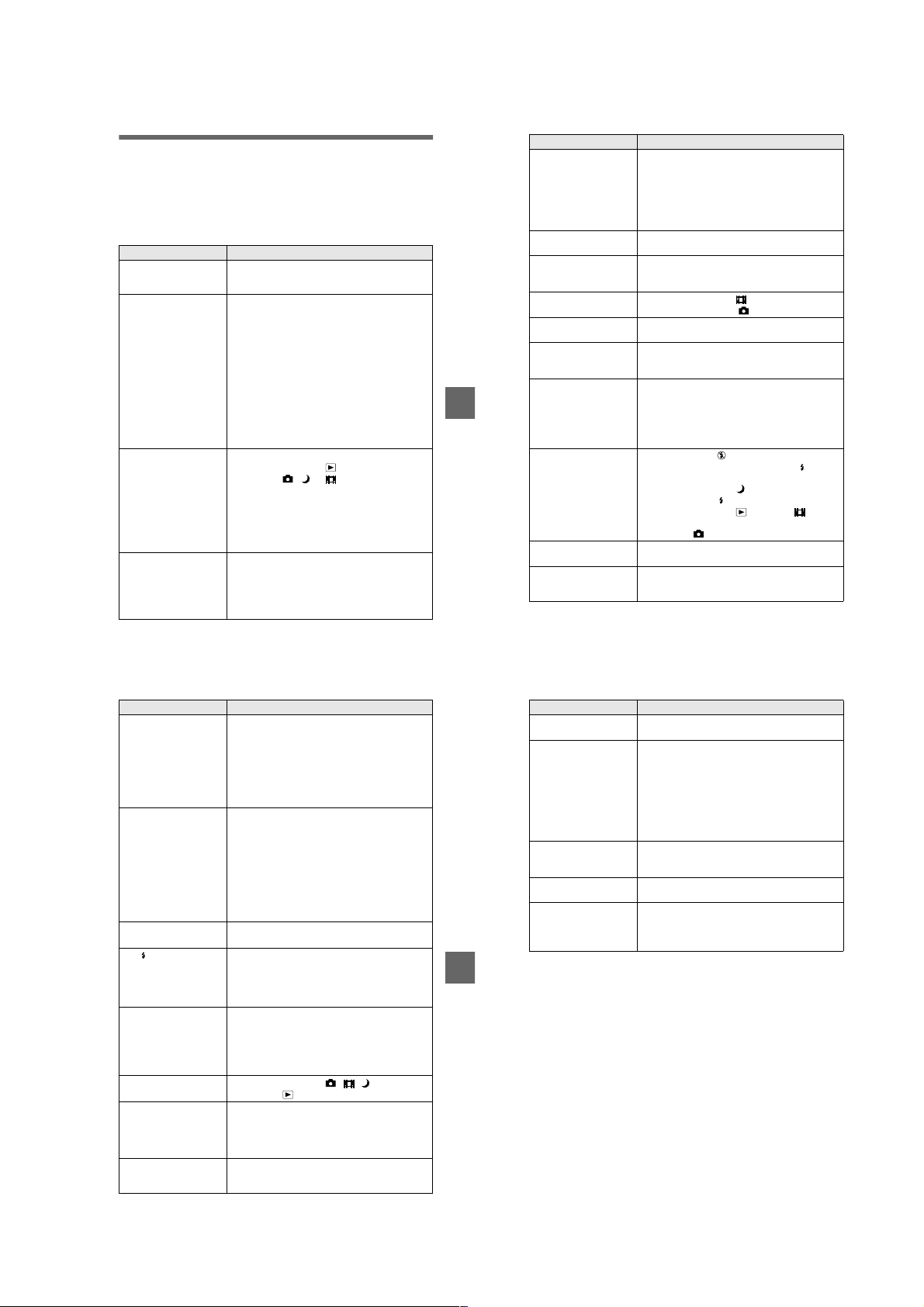
Troubleshooting
If you experience trouble with your camera, first check the following items. Should
your camera still not operate properly after you have made these checks, press the
reset button located on the bottom. (If you press the reset button, the date and time
setting is cleared.) Shou l d your camera still not operate properly, consult your Sony
dealer or local authorized Sony service facility. If code displays (C:
appear on the LCD screen, the self-diagnosis display function is working
(page 83).
Symptom Cause and/or Solution
The power is not turned on
if you press the POWER
button.
Your camera does not
work.
Your camera cannot
record images.
The LCD screen does not
light when the power is
turned on.
Press and hold down the POWER butto n for
t
approximately one second.
•
The battery level is low (the E indicator appears
on the LCD screen).
Replace the alkaline bat t er ie s or charge the
t
battery pack (pages 10, 12).
•
The AC pow er adaptor is not connected securely.
Connect it firmly to the DC IN jack of your
t
camera and a wall outlet (mains) (pages 12, 14).
•
The built-in microcomputer is not working
properly.
Disconnect and then reconnect all power
t
sources after one minute. Then turn the power
on and check that the cam era works properly.
Press the reset button located on the bottom
using a sharp-pointed ob je ct.
•
You cannot record images while charging the flash.
•
The mode dial is set to or SET UP.
Set it to , or (pages 19, 26).
t
•
No “Memory Stick” has been inserted into your
camera.
Insert a “Memory Stick” (page17).
t
•
The write-protect tab on the “Memory St ick” is set
to LOCK.
Set it to the recording position.
t
•
The power was turned off with the LCD screen se t
to OFF the last time the camera was used.
The camera retains the settings from the last
t
time it was used. If you turn the power off with
the LCD screen set to OFF, the LCD is still set
to OFF the next time you turn the power on .
ss
ss:ss
ss
ssss
ssss
)
Symptom Cause and/or Solution
The picture is out of focus. •Your camera is not in macro rec o r di ng mode when
The resizing functi on doe s
not work.
Images recorded in TEXT
mode are blurry.
You cannot record images
in TEXT mode.
You cannot display a print
mark.
The picture is noisy.
The picture is too dark.•You are shooting a subject with a light source
Additional information
The flash does not work. •The flash is set to .
The date and time are
recorded incorrectly.
Vertical streaks appear
when you are shooting a
very bright subject.
you shoot a subject that is abou t 3 to 25 cm (1 3 /1 6
to 9 27/32 inches) from the lens.
Set the macro recording mode (page 53).
t
Press the zoom button to set to the W side.
t
•
The focus preset is select ed.
Cancel the function (page 52).
t
•
Y ou can not resi ze mo ving i mages, t ext images, Clip
Motion and uncompressed images.
•
Light is not striking the subj ect evenly.
Adjust so that the lighting strikes the subject
t
evenly.
•
The mode dial is set to .
Set the mode dial to .
t
•
You cannot display prin t ma rks on moving images,
text images and Clip Motion images.
•
Your camera is placed near a TV or other
equipment that uses stro ng m agnets.
Move your camera away from the TV, etc.
t
behind the subject.
Adjust the exposure (p age 53).
t
•
The brightness of the LCD scree n is to o low.
Adjust the brightness of the LCD screen
t
(page 70).
Set the flash to auto (no indicator) or
t
(page 24).
•
The mode dial is set to .
Set the flash to .
t
•
The mode dial is set to , SETUP or (MPEG
MOVIE).
Set it to .
t
•
The date and time are not set correctly.
Set the correct date an d t ime (page 15).
t
•
The smear phenomenon is happening.
This is not a malfunction.
t
Symptom Cause and/or Solution
The battery life is short.•You are recording/playing back images under
The battery remaining
indicator is incorrect.
Or sufficient battery
remaining indicator is
displayed but the power
runs out soon. (when
using the “InfoLITHIUM”
battery pack)
You cannot charge the
battery pack.
The /CHG lamp flashes
during charging the
battery pack.
Digital zoom does not
function.
Your camera cannot play
back images.
The image and sound are
interfered by noise when
you play back an image on
a personal computer.
The image cannot be
played back on a personal
computer.
extremely cold temperatures.
•
The battery pack is not charged enou gh.
Charge the battery pack fully.
t
•
Alkaline batteries or the battery pack is dead.
Replace the battery (p age 10).
t
•
You are not using the recommended batteries.
Use the recommended batteries (pages 10, 88).
t
•
You have used the camera for a long time in an
extremely hot or an extremely cold location.
•
The battery pack is dead.
Replace the battery pack with a new one
t
(page 10).
•
The battery pack is discharged.
Install a charged battery pack (pages 10, 12).
t
•
A deviation has occurred in the remaining battery
time.
Fully charge the battery pack (page 12).
t
•
The camera is turned on.
Turn the camera off (page 12).
t
•
The battery pack is not installed correctly.
Install the battery pack correctly (page10).
t
•
The battery pack has malfunctioned.
Contact your Sony dealer or local authorized
t
Sony service facility.
•
The digital zoom cannot be used when recording a
moving image with [MOVING IMAGE] set to
[MPEG MOVIE], or the LCD screen is OFF.
•
[DIGITAL ZOOM] is set to [OFF].
Set [DIGIT AL ZOOM] to [ON] in the menu
t
settings.
•
The mode dial is set to , , or SET UP.
Set it to (pages 28, 29).
t
•
You are playing back the file direc t ly fr om the
“Memory Stick.”
Copy the file to the hard disk of the personal
t
computer and then play back the file from the
hard disk (page 35).
Consult the personal computer or software
t
manufacturer.
75
76
Symptom Cause and/or Solution
Y our camera cannot delete
an image.
The power turns off
suddenly.
The image does not
appear on the TV screen.
A file error occurs when
you play back a file.
The picture is
monochrome (black and
white).
Additional information
•
The image is protected.
Cancel the protection (page63).
t
•
If you do not operate the ca m er a for about three
minutes while the power is o n, the camera turns off
automatically to prevent wearing down the battery
(page 11).
The auto-power off functi on (page 11) is
t
activated. Turn on the camera.
•
The battery is discharged.
Replace it with a charged battery or new
t
alkaline batteries.
•
The video output signal se tti ng of your camera is
incorrect.
Change the setting (page 70).
t
•
The image size is larger than 160 0×1200 (DSCP50) or 1280×960 (D SC-P30).
•
The camera is set to TEXT mode.
Cancel TEXT mode (page 49).
t
•
P. EFFECT is set to B&W mode.
Cancel B&W mode (page 55).
t
77
78
1-19
Page 26
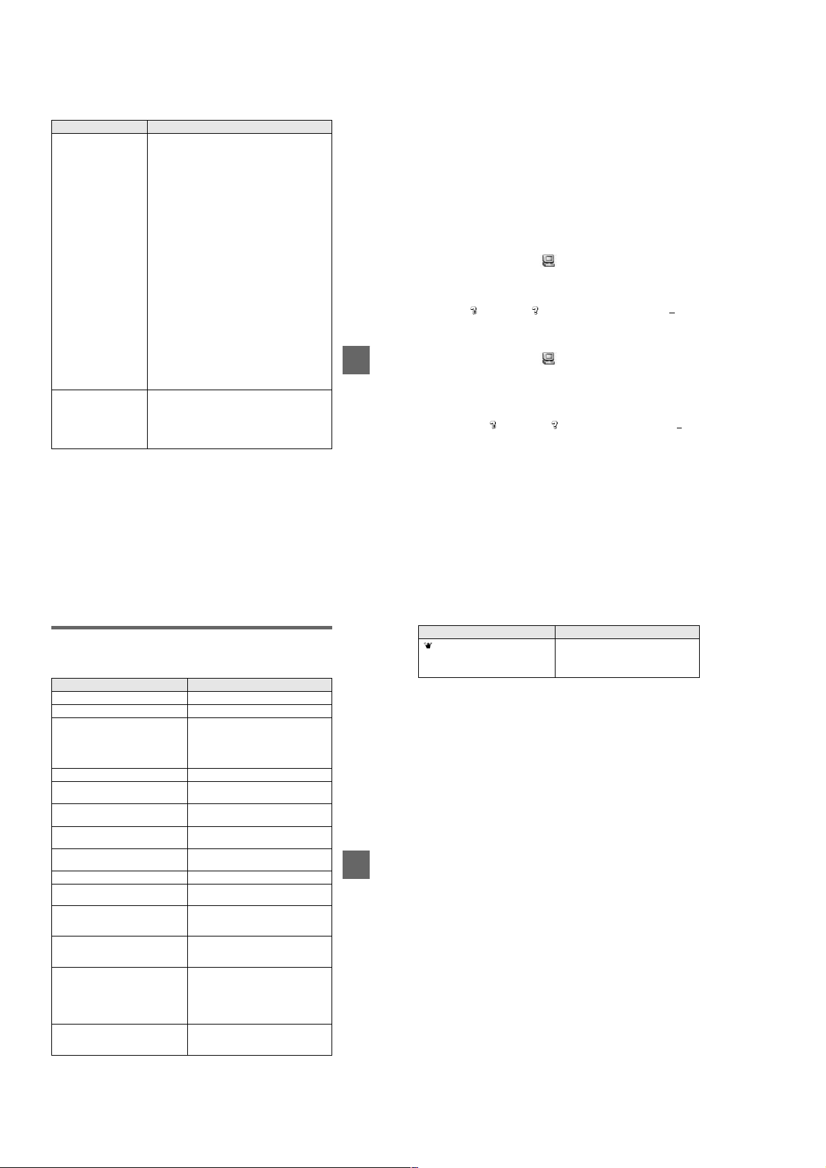
Symptom Cause and/or Solution
Your personal computer
does not recognize your
camera.
No function works though
the power is on.
•
The battery level is low.
Use the AC power adaptor (not su pplied)
t
(page 14).
•
The camera is turned off.
Turn on the camera.
t
•
The USB cable is not connected firmly.
Disconnect the USB cable , a nd connect it again
t
firmly. Make sure that “USB MODE” is
displayed on the LCD screen (pages 32, 34).
•
The USB connectors on your personal computer are
connected to other equipment besides the keyboard,
the mouse, and your camera.
Disconnect the USB cab le s exce pt for the ones
t
connected to the keyboard, the mouse, and your
camera.
•
The USB driver is not installed.
Install the USB driver (page32).
t
•
[USB CONNECT] is set to [PTP] in the setup
settings.
Set it to [NORMAL] (page 70).
t
•
Since the camera is connec te d t o a computer with
the USB cable before installing the USB driver, the
drive is not recognized by the computer.
Delete the drive which is not recognized, then
t
install the USB driver. For details, se e the
procedure on page 80.
Remove the battery pack, then install it again
t
after about one minute. If the function still do
not work, press the reset button located on the
bottom using a sharp-po i nt ed object. (If you
press the reset button, the date and time setting
is cleared.)
Reinstall the USB driver when using Windows 98, Windows
98SE, Windows Me and Windows 2000 Professional
Perform all steps without skipping.
T urn on your computer and allow Windows to load.
1
Connect the USB jack on the camera and the computer with the
2
supplied USB cable.
Insert a “Memory Stick”.
3
Connect the AC power adaptor to your camera and then to a wall
4
outlet (mains), and turn on the power of your camera.
Open “Device Manager” on Windows.
5
For Windows 98, Windows 98SE and Windows Me users:
Open [Control Panel] from [ My Computer], then double-click
1
[System].
“System propertie s ” is displayed. Click the [Device Manager] tab located at
2
the top.
Click [ Sony DSC] in [ Other devices], then click the [Delete (E)]
3
button located at the lower-right corner.
For Windows 2000 Professional users:
Log in with the permission of administrator.
*
Open [Control Panel] from [ My Computer], then double-click
1
Additional information
[System].
“System properties” is displayed. Click the [Hardware] tab located at the top,
2
then click the [Device Manager (D)] button.
Click [View] in [Device Manager], then click [Devices by type (E)].
3
Right-click [ Sony DSC] in [ Other devices], then click [D el ete (E)].
4
After the message appears to verify that you delete the device, click
6
“OK.”
Turn off the camera, disconnect the USB cable, and restart the
7
computer.
Install the USB driver in the supplied CD-ROM to the computer
8
following the procedure on page 32.
Warning and notice messages
Various messages appear on the LCD screen. Check the corr esponding descriptions
in the following list.
Message Meaning
NO MEMORY STICK No “Memory Stick” has been inserted.
SYSTEM ERROR Turn the power off and on again.
MEMORY STICK ERROR
FORMAT ERROR Failed to format the “Memory Stick.”
MEMORY STICK LOCKED The write-protect tab on the “Memory
NO MEMORY SPACE The capacity of the “Memory Stick” is
NO FILE No image has been recorded on the
FILE ERROR An error occurred while playing back the
FILE PROTECT The image is protected against er asure.
DIRECTORY ERROR A directory with the same name already
IMAGE SIZE OVER You are playing back an image of a size
INVALID OPERATION You are playing back a file that was
E
CANNOT DIVIDE • The file is not long enough to be
•
The inserted “Memory Stick” cannot
be used with your camera, or i s
damaged.
•
The “Memory Stick” is not inserted
correctly.
Stick” is set to the LOCK position.
full, and you cannot record im ages.
“Memory Stick.”
image.
exists.
that cannot be played back wi t h your
camera.
created on equipment other than your
camera.
The battery level is low or zero.
Depending on the conditio ns of use or
the type of battery pack, the indicator
may flash even though there is still 5 to
20 minutes of remaining battery time
left.
divided.
• The file is not a moving i m age.
79
80
Message Meaning
Additional information
The amount of light is not su fficient or
the shutter speed is too slow. (Mount the
camera on a tripod or ot herwise secure
the camera in place.)
81
82
1-20
Page 27
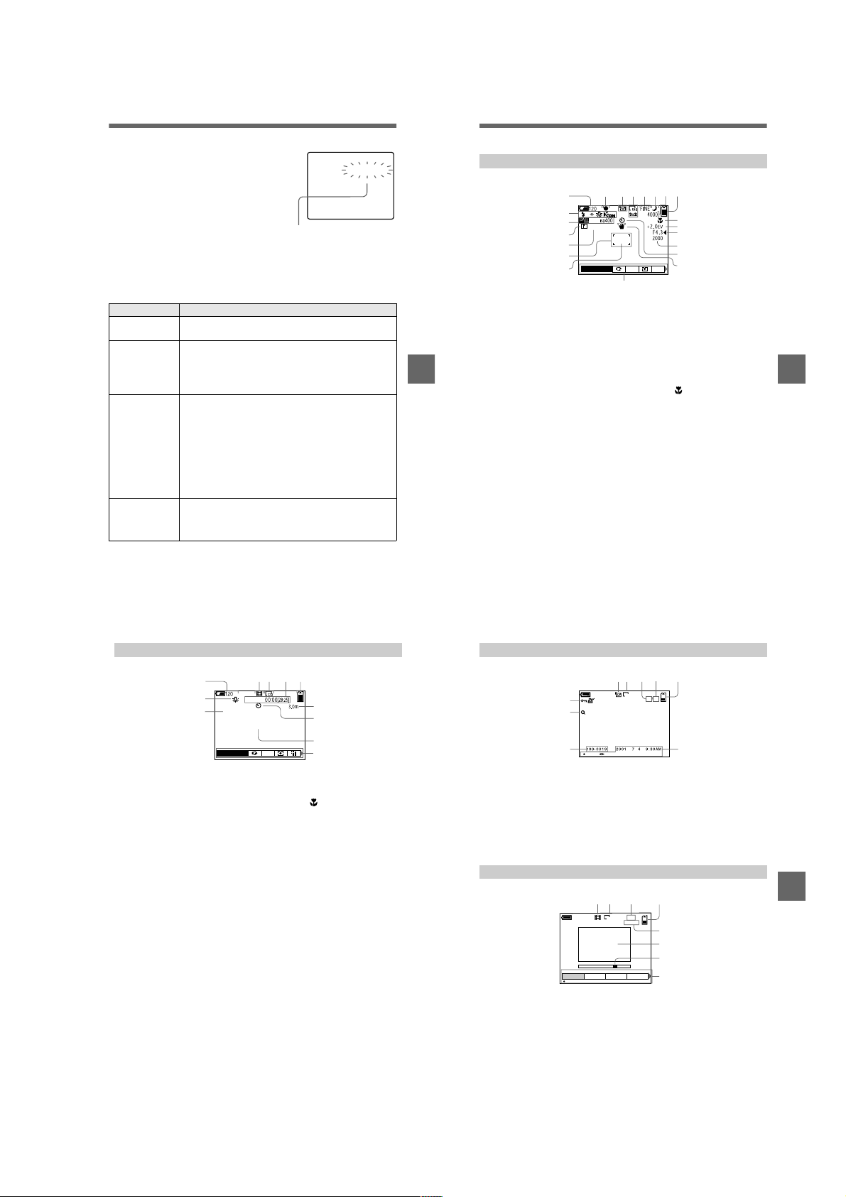
Self-diagnosis display
Your camera has a self-diagnosis display. This
function displays the camera condition on the
LCD screen with a comb i nation of a letter and
four digits of numbers. If this occurs, check the
following code chart. The code informs you of the
camera’s curr ent condition. The last two digits
(indicated by ss) will differ de pending on the
state of the camera.
Self-diagnosis display
•
C:ss:
You can reverse the camera
malfunction yourself.
•
E:ss:
Contact your Sony dealer or local
authorized Sony service facility.
First three digits Cause and/or Corrective Action
•
C:32:
ss
C:13:
ss
E:92:
ss
E:61:
ss
E:91:
ss
If you are unable to solve the problem even after trying the corrective
actions a few times and when the camera is not reset even if you press the
reset button located on the bottom, contact your Sony dealer or local
authorized Sony service facility.
There is trouble with your camera’s hardware.
Turn the power off and on again.
t
•
An unformatted “Memory Stick” is insert ed.
Format the “Memory Stick” (page 69).
t
•
The inserted “Memory Sti ck” cannot be used with your
camera, or is damaged.
Insert a new “Memory Stick” (page 17).
t
•
You are using a battery pack that is not “InfoLITHIUM”
compatible.
Use an “InfoLITHIUM” battery pack.
t
•
You installed or removed the “InfoLITHIUM” battery pack
when using the AC adapter.
Turn the power of and on again.
t
•
A camera malfunction that you cannot reverse has occurred.
Contact your Sony dealer or local aut horized Sony
t
service facility and inform them of the 5-digit service
code. (example: E:92:10)
•
A camera malfunction that you cannot reverse has occurred.
Contact your Sony dealer or local aut horized Sony
t
service facility and inform them of the 5-digit service
code. (example: E:61:10)
C:32:ss
ss
ss
83
LCD screen indicators
The indicators during recording still images
qd
890 qsqa
1
min
2
3
SOLARIZE
4
5
6
7
+
WB
EV
qf
qg
qh
qj
qk
ql
w;
ISO
wa
A Battery remaining indicator
B Flash mode/red eye reduction/
white balance/AF illuminator
indicator
C Date/time/ISO number indicator
D Sharpness indicator
Additional information
E Picture effect indicator
F AF frame
G Spot light-metering cross hair
H AE/AF lo ck indicator
I Recording mode indicator
J Image size indicator
K Image quality indicator
L TWILIGHT mode indicator
M Remaining number of
recordable images indicator/
Self-diagnosis function
indicator
N Remaining memory capacity
indicator
O Macro /focus mode 9
indicator
P EV level indicator
Q Aperture value indicator
R Shutter speed indicator
S Self-timer indicator
T Light amount warning indicator
U Menu and guide menu
Pressing MENU switches the
menu on/off.
Additional information
85
The indicators during recording moving images
45 6
1
min
2
3
STANDBY
SOLARIZE
7
+
WB
EV
A Battery remaining indicator
B White balance indicator
C Picture effect indicator
D Recording mode indicator
E Image size indicator
F Recording time (maximum
recordable time) indicator/
Self-diagnosis function
indicator
G Remaining memory capacity
indicator
H Macro /focus mode 9
indicator
I Self-timer indicator
J Spot light-metering cross hair
K Menu and gu id e m e nu
Pressing MENU switches the
menu on/off.
When playing back still images
45 76
120
min
8
9
0
qa
A Protect/print mark indicator
B Zoom scaling indicator
C File name
D Recording mode indicator
E Image size indicator
F Image number
1
2
3
640
x1.3
FILE BACK/NEXTPLAY
8
11/12
9
G Number of stored images in
“Memory Stick”
H Remaining memory capacity
indicator
I Recording date of the playback
image/menu and guide menu
When playing back moving images
4
6/8
0:12
5
Additional information
60
min
12 3
320
6
7
DELETE
PROTECT
OK
A Recording mode indicator
B Image size indicator
C Image number/number of
stored images in “Memory
Stick”
D Remaining memory capacity
indicator
PRINT SLIDE
8
E Counter
F Playback image
G Play bar
H Menu and guide menu
(play/pause/fast-forward/
rewind)
86
87
1-21
Page 28

Notes on Using
Batteries
Power save mode
When operating the camera with size
AA alkaline batteries, set POWER
SAVE in the SET UP screen to ON.
This increases the battery efficiency
and life when recording still images.
When POWER SAVE is ON
•
When recording with the L CD screen
turned on, the LCD scr een turns off
while the flash is charging (while the
/CHG lamp flashes).
•
The time from when you pr ess the
shutter button until the image is
recorded is slightly longer than when
POWER SAVE is OFF.
•
The focus is only aligned when the
shutter button is depressed halfway,
even when auto focusing is activated.
Power save mode
•
The factory setting is ON (page 70).
•
Power save mode is also effective
when using an “InfoLITHIUM”
battery pack (NP-FS11, not
supplied), but in this case recording
can be performed more com f ortably
by setting POWER SAVE in the SET
UP screen to OFF.
Handling precautions for size
AA batteries
•
The batteries may be hot
immediately after using the camera.
Wait until the batteries have cooled
before removing them.
•
Remove the batteries when yo u w i ll
not be using the camera for a long
time.
•
Do not disassemble batteri es, short
the terminals with metallic obje cts, or
place batteries in or near he at
sources.
•
Be sure to replace both batteries at
the same time. In addition, do not
mix new and old batt eries or diff erent
types of batteries such as alkaline and
nickel metal hydride batterie s.
Batteries that can be used
•
“InfoLITHIUM” battery pack
(NP-FS11) (recommended, not
supplied)
•
Size AA alkaline batteries (2)
•
Size AA nickel metal hydride
batteries (2)
•
Size AA nickel-cadmium batteries
(2)
Notes
•
When using size AA alkaline batteries, we
recommend Sony Stamina alkaline
batteries. Other batteries may not bring out
the full performance of the camera.
•
When using the camera in low temperat ure
environments, use the “InfoLITHIUM”
battery pack (NP-FS11, not supplied). The
performance of alkaline batteries drop s
significantly at low temperatures, making
use impossible.
•
Nickel metal hydride batteries and nickelcadmium batteries can be use d, but the
battery remaining time may not be
displayed correctly.
•
Manganese and primary lithium batteries
cannot be used with the camera.
88
1-22 E
1-22
Page 29
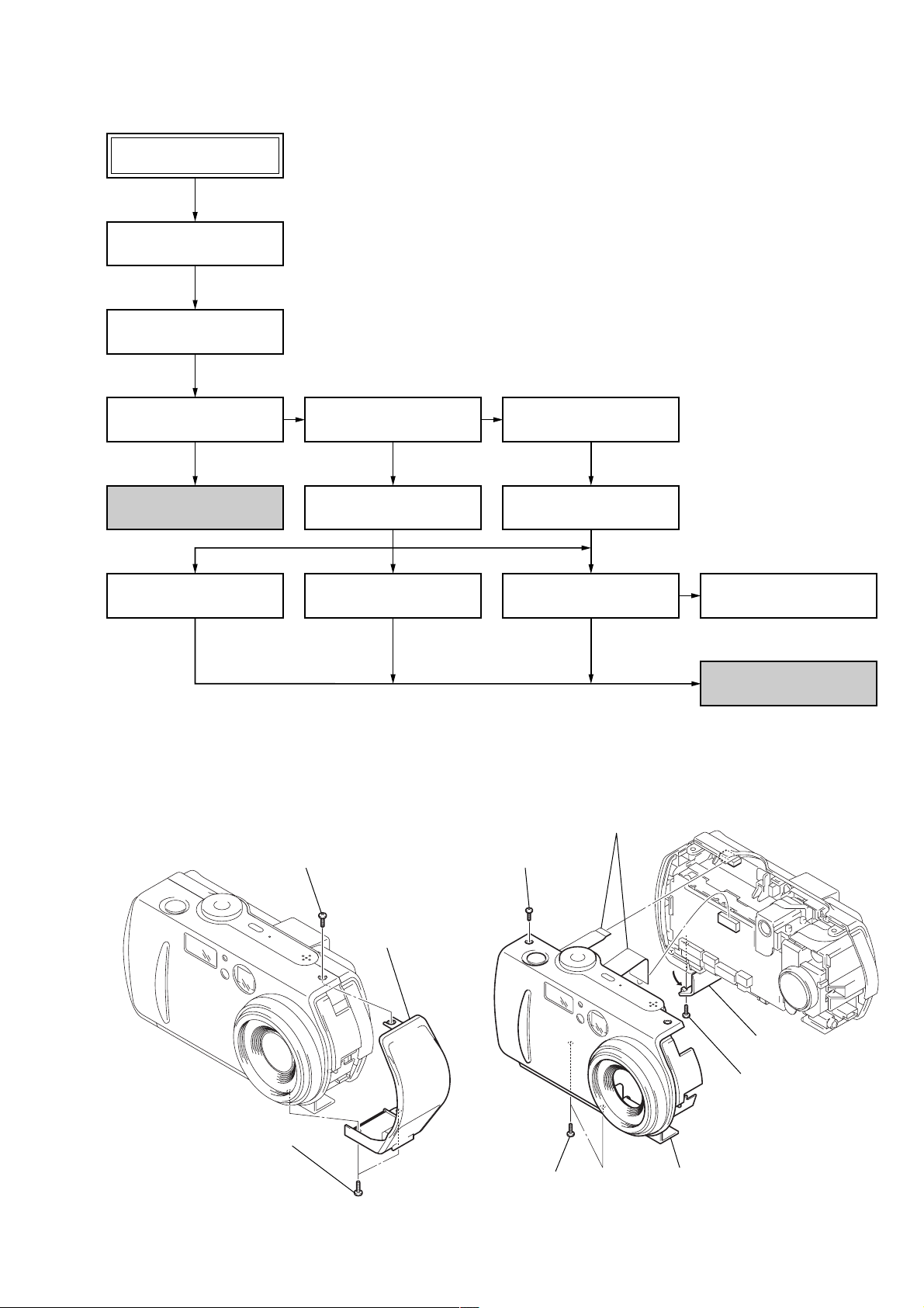
• This set can be disassembled in the order shown below.
DSC-P30/P50
2-1. CABINET (R) ASSEMBLY
(Page 2-1)
2-2. CABINET (FRONT) BLOCK
ASSEMBLY (Page 2-1)
DSC-P30/P50
SECTION 2
DISASSEMBLY
2-3. DD-158 BOARD
(Page 2-2)
SERVICE POSITION
(DD-158 BOARD)
(Page 2-2)
2-6. OPTICAL FINDER
(Page 2-3)
2-4. CHASSIS (MAIN)
ASSEMBLY (Page 2-3)
2-5. LENS BLOCK ASSEMBLY
(Page 2-3)
2-7. ZOOM LENS
(Page 2-3)
Note: Follow the disassembly procedure in the numerical order given.
2-1. CABINET (R) ASSEMBLY
1 Screw
(M2)
2-8. JK-206 BOARD
(Page 2-4)
2-9. DC JACK
(Page 2-4)
2-10. SY-66 BOARD
(Page 2-4)
2-11. LCD MODULE
(Page 2-4)
SERVICE POSITION
(SY-66 BOARD)
(Page 2-5)
2-2. CABINET (FRONT) BLOCK ASSEMBLY
6 Two flexible boards
(CN501, 708)
3 Screw
(M2)
2 Two screws
(M2)
3 Cabinet (R)
assembly
4 Two screws
2-1
(M2)
1 Open the MS lid.
2 Screw
(M2)
5 Cabinet (front)
block assembly
Page 30
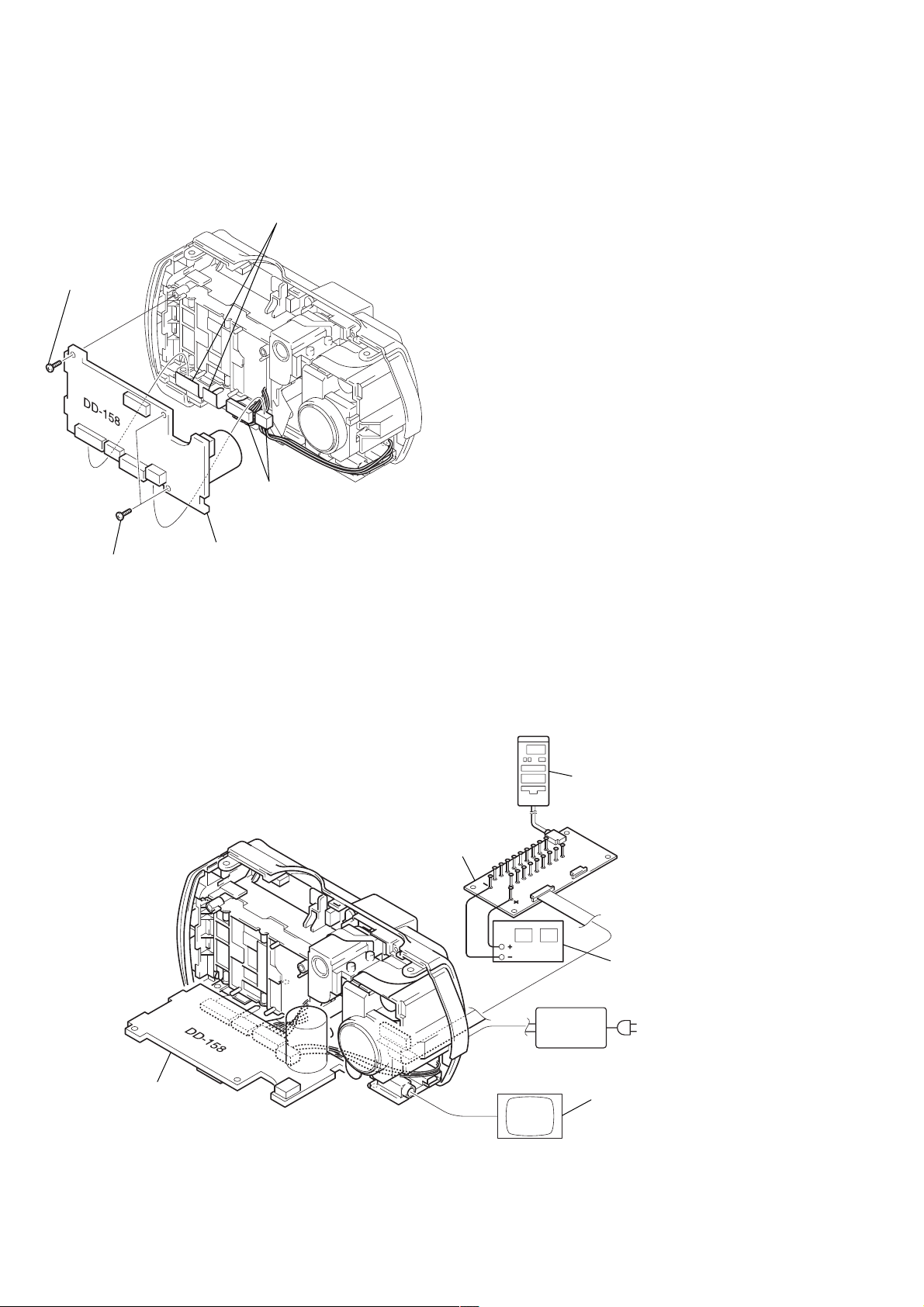
2-3. DD-158 BOARD
3 Screw
(DIA. 1.7 × 4)
1 Two flexible boards
(CN003, 004)
2 Two connectors
(CN001, 002)
4 Screw
(DIA. 1.7 × 4)
5 DD-158 board
[SERVICE POSITION (DD-158 BOARD)]
Note 1: Don’t use the 12 pin flexible board of CPC-9 jig.
Note 2: The old CPC-9 jig (Parts code: J-6082-393-B)
It causes damage to the unit.
cannot be used, because it cannot operate
the adjustment remote commander.
Adjusting remote
commander
CPC-9 jig
(J-6082-393-C)
18
1
Regulated power supply
(6.0 to 7.2 Vdc)
DD-158 board
18
1
AC power
adaptor
Color monitor
AC IN
2-2
Page 31

2-4. CHASSIS (MAIN) ASSEMBLY 2-6. OPTICAL FINDER
1 Two screws
(DIA. 1.7 × 4)
2 Optical finder
2 Chassis (main) assembly
2-5. LENS BLOCK ASSEMBLY 2-7. ZOOM LENS
1 Two screws
(DIA. 1.7 × 4)
4 Screw
(DIA. 1.7 × 4)
6 Connector
(CN702)
1 Flexible board
(CN182)
3 Two screws
(DIA. 1.7 × 4)
5 Lens block
assembly
2 Two flexible boards
(CN101, 181)
1 Screw
(DIA. 1.7 × 4)
2 Screw
(DIA. 1.7 × 4)
4 Zoom lens
3 Two bosses
2-3
Page 32

2-8. JK-206 BOARD 2-10. SY-66 BOARD
2 SY-66 board
2 Flexible board
1 JK-206 board
(CN201)
1 Four screws
(M1.7 × 5)
3 Two flexible board
(CN805, 806)
2-9. DC JACK 2-11. LCD MODULE
6 LCD module
5 Two claws
1 Claw
2 DC jack
1 Four screws
(1.7 × 3)
4 Two claws
3 Light guide plate (1.5) block
2 Ground plate (LCD)
2-4
Page 33

[SERVICE POSITION (SY-66 BOARD)]
Note 1: Don’t use the 12 pin flexible board of CPC-9 jig.
It causes damage to the unit.
Note 2: The old CPC-9 jig (Parts code: J-6082-393-B)
cannot be used, because it cannot operate
the adjustment remote commander.
Adjusting remote
commander
CPC-9 jig
(J-6082-393-C)
Regulated power supply
(6.0 to 7.2 Vdc)
1
18
1
18
DC jack
AC power
adaptor
AC IN
Color monitor
JK-206 board
Cabinet (rear)
block assembly
DD-158 board
Base
SY-66 board
Optical finder
Zoom lens
• SIDE A
• SIDE B
Optical finder
JK-206 board
Zoom lens
SY-66 board
Color monitor
Adjusting remote
commander
CPC-9 jig
(J-6082-393-C)
DD-158 board
18
1
DC jack
Note 1: Don’t use the 12 pin flexible board of CPC-9 jig.
Note 2: The old CPC-9 jig (Parts code: J-6082-393-B)
It causes damage to the unit.
cannot be used, because it cannot operate
the adjustment remote commander.
Regulated power supply
(6.0 to 7.2 Vdc)
AC power
adaptor
AC IN
2-5
Page 34

2-12. CIRCUIT BOARDS LOCATION
DD-158
DC IN, DC/DC CONVERTER,
FLASH CHARGE
JK-206
(JACK)
SY-66
CAMERA PROCESS, LENS DRIVE,
CAMERA DSP, VIDEO, MEMORY,
SH DSP, CLOCK GENERATOR, USB I/F,
FRONT CONTROL, LCD DRIVE,
( )
TIMING GENERATOR
CD-319
(CCD IMAGER)
2-13. FLEXIBLE BOARDS LOCATION
Strobo flexible block assembly
FP-052
FP-053
Optical finder
FP-054
Zoom lens
FP-058
2-6
E
Page 35

3-1. OVERALL BLOCK DIAGRAM
DSC-P30/P50
SECTION 3
BLOCK DIAGRAMS
FOCUS
SENSOR
FLASH UNIT
LENS
MM
ZOOM
SENSOR
OPTICAL VIEWFINDER BLOCK
M
ZOOM
SENSOR
DD-158 BOARD
METER
H
Z SENS RST
F SENS RST
CHARGING
CAPACITOR
IRIS
M
DRIVE +
DRIVE–
HALL+
IC183
(SEE PAGE 4-13)
CD-319 BOARD SY-66 BOARD
T501
IC401
CCD IMAGER
(SEE PAGE 4-6)
IC184, 185
(SEE PAGE 4-13)
IRIS DRIVE
HALL AMP
ZOOM MOTOR
DRIVE
FOCUS MOTOR
DRIVE
IC182 (2/2)
OVF ZOOM
DRIVE
(SEE PAGE 4-13)
CCD OUT
V1A, V1B, V2, V3A,
V3B, V4, VSUB CNT
IC182 (1/2)
IRIS
(MECHA SHUTTER)
DRIVE
(SEE PAGE 4-13)
HALL AD
ST 5V
STB CHG
XSTB FULL
H1, H2
IC102
S/H, AGC,
A/D CONV.
(SEE PAGE 4-12)
IC101
TIMING
GENERATOR
(SEE PAGE 4-11)
MSHUT ON
IC186
EVR
(D/A CONVERTER)
(SEE PAGE 4-14)
PE EN1,
PE DIR1A, PE DIR1B
PE EN0,
PE DIR1A, PE DIR0B
IC187
OVF ZOOM
CONTROL
(SEE PAGE 4-14)
PE DAC LEVEL
CNTC
Z SENS RST
F SENS RST
12
DATA BUS
1, 2
CAM SI, CAM SO, XCAM SCK
OVF RST SENSOVF RST SENS
STRB ON
STRB AIN
IC301
CAMERA
DSP
(SEE PAGE 4-16)
Y OUT
C OUT
PANEL Y
PANEL R-Y
PANEL B-Y
ADDRESS BUS14 14
X781
48MHz
CAM SI, CAM SO, XCAM SCK
DATA BUS16 16
IC504
16M
FLASH ROM
(SEE PAGE 4-21)
IC505
16M SDRAM
(SEE PAGE 4-21)
16
14
IC781
CLOCK GEN.
(SEE PAGE 4-22)
IC302
64M
SDRAM
(SEE PAGE 4-17)
16
20
16
12
ADDRESS BUS ADDRESS BUS
DATA BUS DATA BUS
TG CLK
MC CLK
USB CLK
AU CLK
CAM SI, CAM SO, XCAM SCK
V OUT ON
16
20
HALL AD
LCD DD ONLCD DD ON
IC507
EEPROM
(SEE PAGE 4-21)
IC802
EVR
(D/A CONVERTER)
(SEE PAGE 4-25)
IC501
MC CAM,
SH DSP
(SEE PAGE 4-19)
Y OUT
C OUT
V OUT ON
PANEL Y
PANEL R-Y
PANEL B-Y
BL LEV
BL ON
(SEE PAGE 4-18)
USB DATA
IC651
VIDEO AMP
IC801
LCD
DRIVE
(SEE PAGE 4-25)
IC806
BACK LIGHT
CONTROL
(SEE PAGE 4-26)
IC601
USB I/F
(SEE PAGE 4-22)
MS DIO, MS BS, MS SCLK
JK-206 BOARD (2/3)
(SEE PAGE 4-29)
VIDEO OUT
VR
VG
VB
IC804
LCD TIMING
GENERATOR
(SEE PAGE 4-26)
Q812, 814, 817
BACK LIGHT
DRIVE
JK-206 BOARD (3/3)
D+ USB D+
D– USB D–
(SEE PAGE 4-29)
VIDEO OUT
LCD901
COLOR
MONITOR
D901
BACK LIGHT
LCD
J201
CN204
CN202
USB
MS
SOCKET
BRIGHT
LEVEL
SENSOR
BT901
BATTERY
TERMINAL
J001
DC IN
+
S
–
05
BATT SIG
DRY BATT DET1, 2
STRB ON
STRB AIN
ACV UNREG
BATT UNREG
SYS DD ON
LCD DD ON
IC001
DC/DC
CONTROL
(SEE PAGE 4-37)
JK-206 BOARD (1/3)
(SEE PAGE 4-29)
CAM 15V
BUZZER 15V
PANEL 13.5V
CAM –7.5V
PANEL 3.2V
D 1.8V
M 5V
BL VO–
A 3.2V
A 4.9V
EVER 5.5V
ST 5V
BT201
LITHIUM
BATTERY
VL 3V
EVER 5.5V
D408
SYS DD ON
BATT SIG
DRY BATT DET1, 2
IC403
INITIAL
RESET,
BACK UP VCC
(SEE PAGE 4-23)
XHI SCK
HI SI, HI SO,
STB CHARGE
XSTB FULL
IC402
FRONT
CONTROL
(SEE PAGE 4-24)
UNREG SCK, UNREG SOUNREG SCK, UNREG SO
XRESET
EVER B+
BACK UP VCC
KEY AD3
ZOOM
SWITCH
FUNCTION
KEY
BEEP
XAE LOCK SW, XSHTR SW
XPB ON, XSET UP, MODE DIAL
XPWR ON
KEY AD0, 1
BZ701
BUZZER
CONTROL SWITCH BLOCK
(SEE PAGE 4-23)
SHUTTER
SWITCH
MODE
DIAL
POWER
ON/OFF
3-1 3-2
Page 36

DSC-P30/P50
3-8. POWER BLOCK DIAGRAM 1
TERMINAL
POWER BLOCK 2
(SEE PAGE 3-17)
J001
DC IN
BT901
BATTERY
+
S
–
TO
A
DD-158 BOARD
BATT /XEXT
D002, 014
Q106
Q001, 002
Q007
D003
Q067, 073
CHARGE
CONTROL
Q067, 073
SWITCH
CONTROL
Q005, 006
DRY
BATTERY
DETECT
INIT CHARGE
FAST CHARGE
DRY BATT IN1
DRY BATT IN2
CN001
ACV UNREG
2
BATT/XEXT
1
ACV GND
3
CN002
BATT UNREG/+
6
7
DRY BATT DET1
4
DRY BATT DET2
3
BATT SIG BATT SIG
5
BATT GND/-
1
2
CN003
EVER 3.2V
2
SYS DD ON
15
FAST CHARGE
11
INIT CHARGE ON
9
XCS DDCON
5
UNREG SO
4
UNREG SCK
3
DRY BATT IN1
31
DRY BATT IN2
30
BATT SIG
1
SYS
DD ON
XCS DDCON
UNREG SO
UNREG SCK
EVER 3.2V
Q003
60
57
44
45
46
47
48
56
58
IN 2-
CONT
XCS
DATA
CLK
RST
LD ON
VCC1
CH2UP
F001
F002, 005
F005
F003, 006
IC001
DC/DC CONTROL
(SEE PAGE 4-37)
AMP IN-
AMP OUT
L004
OUT 2n
VCC2
OUT 6p
OUT 6n
OUT 6s
VIN 6-
VCC4
OUT 3p
OUT 3n
VIN 3-
OUT 10
IN 10-
SCPIN
OUT 5p
OUT 5n
OUT 5s
VIN 5-
VCC3
VCC5
OUT 4p
OUT 4n
VIN 4-
OUT 9
IN 9-
SCP 9
SWITCHING
35
41
28
29
18
50
19
32
33
54
22
4
5
3
10
38
39
43
52
42
20
30
31
53
23
80
1
Q019
D011
D013
D012
ST 5V
D009
L002
L005
Q501, 502
D010
L100 L013
Q018, 021
SWITCHING
Q017, 020
SWITCHING
L001
(SEE PAGE 4-36)
Q024
L020
Q023
L021
Q016
SWITCHING
D008
IC002
DC/DC
CONVERTER
Q011, 014
SWITCHING
Q013
SWITCHING
Q012, 015
SWITCHING
D004 D005
L016
D006 D007
L101
L006
L007
L014
T501
L012
L011
Q010
EMERGENCY
DETECT
L017
L018
Q026, 027
CAM –7.5V
L008
L009
L010
Q032, 034
PANEL 13.5V
REG
REG
A 4.9V
D 3.2V
Q029
SWITCH
AF LED 5V SENS-A
BATT UNREG
BATT /XEXT
EVER 5.5V
A 4.9V
D 3.2V
M 5V
ACV UNREG
D 1.8V
BL VO –
CAM –7.5V
A 3.2V
PANEL 3.2V
BUZER 15V
CAM 15V
L019
PANEL 13.5V
LCD DD ON
CN501
CN004
CN003
FLASH UNIT
11
XE-A
ı
16
4
AF ILLUMINATOR
11
13
TO
POWER BLOCK 2
B
9
6
7
ı
8
(SEE PAGE 3-17)
TO
POWER BLOCK 2
C
(SEE PAGE 3-17)
20
21
12
10
24
25
18
21
26
27
14
28
29
16
10
12
13
05
3-15 3-16
Page 37

3-9. POWER BLOCK DIAGRAM 2
DSC-P30/P50
JK-206 BOARD (1/2)
(SEE PAGE 4-29)
BT201
LITHIUM BATTERY
POWER BLOCK 1
(SEE PAGE 3-15)
POWER BLOCK 1
(SEE PAGE 3-16)
TO
TO
A
C
CN201 (1/2)
CN704
EVER 3.2V
38
SYS DD ON
25
FAST CHARGE
29
INIT CHARGE ON
31
XCS DDCON
35
UNREG SO
36
UNREG SCK
37
DRY BATT IN1
9
DRY BATT IN2
10
BATT SIG
39
ACV UNREG
33
34
BUZER 15V
30
LCD DDON
27
CAM 15V
32
CAM – 7.5V
26
19
D 1.8V
ı
22
A 3.2V
11
12
M 5V
15
16
13
BL VO–
14
PANEL 3.2V
24
VL 3V
18 1
Q703 704
BUZZER AMP
(SEE PAGE 4-23)
A 3.2V
CN703 (1/2)
D408
EVER 5.5V
BATT/XEXT
SY-66 BOARD
VBAT
3
VRO
8
7
VIN
BATT UNREG
D 1.8V
CLOCK GEN.
(SEE PAGE 4-22)
FB781
L781
IC403
INITIAL RESET
BACK UP VCC
(SEE PAGE 4-23)
IC781
VOUT
6
4
CS
5
RESET
Q405
BATTERY
CHARGE
DETECTOR
IC301
CAMERA
DSP
(SEE PAGE 4-16)
L306
L303
FB301
26 (BATT IN)
15 BATT IN
6 XRESET
31
14
37
36
27
28
29
89
17
78
79
94
93
92
FB302
BACKUP VCC
FRONT CONTROL
(SEE PAGE 4-24)
SYS DD ON
BATT/XEXT
FAST CHARGE
INIT CHARGE
XCS DDCON
UNREG SO
UNREG SCK
DRY BATT IN1
DRY BATT IN2
BATT SI
BATT SO
ACV SENS
BATT SENS
DD CON SENS
IC302
64M SDRAM
(SEE PAGE 4-17)
FB304
IC402
IC651
VIDEO AMP
(SEE PAGE 4-18)
L653
CAM 15V
CAM –7.5V
A 3.2V
21 LCD DD ON
L501
D 3.2VD 3.2V
D 1.8V
A 3.2V
M 5V
BL VO–
PANEL 3.2V
IC501
MC CAM,
SH DSP
(SEE PAGE 4-19)
L502
Q102 – 105
18CAM DD ON
16MS POWER ON
D403
17LCD POWER
25VOUT ON
D402
Q305 – 309
BUFFER
(SEE PAGE 4-18)
L307
Q311, 312
L183
IC184
IRIS
DRIVE
(SEE PAGE 4-13)
D101
D102
HALL BIAS/GAN
(SEE PAGE 4-13)
D 3.2V
FB113
FB112
IC185
IRIS DRIVE
HALL AMP
CONTROL
M 5V
L184
IC186
EVR
(D/A CONV.)
(SEE PAGE 4-14)
L186
L182
IC504
16M
FLASH
(SEE PAGE 4-21)
FB503 FB502
(SEE PAGE 4-12)
L181
IC183
FOCUS/
ZOOM
DRIVE
(SEE PAGE 4-13)
IC505
16M
SDRAM
(SEE PAGE 4-21)
FB110
IC102
S/H, AGC,
A/D CONV.
D 3.2V
L101
L102
FB111
IC101
TIMING
GENERATOR
(SEE PAGE 4-11)
L185
IC182
IRIS
(MECHA SHUTTER)/
OVF ZOOM
DRIVE
(SEE PAGE 4-13)
IC507
EEPROM
(SEE PAGE 4-21)
L103
FB114
(SEE PAGE 4-22)
CN101
CAM 15V
CAM –7.5V
IC187
OVF ZOOM
CONTROL
(SEE PAGE 4-14)
IC601
USB I/F
FB601
1
18
CAM 15V
CAM –7.5V
Q186
Q182
Q701, 702
CD-319 BOARD
CN401
20
3
CN182
7
CN181
20
7
CN708
5
10
CN703
(2/2)
3
CN806
1
6
FB401
(SEE PAGE 4-6)
OVF SENS VCC
F SENS VCC
Z SENS VCC
D 3.2V
D 3.2V
D 3.2V
BL L
PANEL 3.2V
L401
IC401
CCD
IMAGER
OPTICAL VEWFINDER BLOCK
FOCUS
SENSOR
FOCUS
SENSOR
ZOOM
SENSOR
LENS BLOCK
CONTROL
SWITCH
BLOCK
JK-206 BOARD
(2/2)
(SEE PAGE 4-29)
CN201
(2/2)
16
CN204
SOCKET
D901
BACK LIGHT
MS
POWER BLOCK 1
(SEE PAGE 3-16)
D803
CN805
VDD
7
VDDG
9
LCD901
COLOR
LCD
MONITOR
PANEL UNIT
PANEL 13.5V
28
CN705
EVER 5.5V
1
TO
2
BATT/XEXT
9
11
12
13
10
05
BATT UNREG
D 3.2V
A 4.9V
B
PANEL 13.5V
D 3.2V
A 4.9V
Q808, 810
IC806
BACK LIGHT
DRIVE
(SEE PAGE 4-26)
Q804
L803
IC804
LCD TIMING
GENERATOR
(SEE PAGE 4-26)
L802
IC802
EVR
(D/A CONVERTER)
(SEE PAGE 4-25)
L801
IC801
LCD
DRIVE
(SEE PAGE 4-25)
IC803
VREF AMP,
VCO
(SEE PAGE 4-26)
3-17 3-18 E
Page 38

SECTION 4
PRINTED WIRING BOARDS AND SCHEMATIC DIAGRAMS
THIS NOTE IS COMMON FOR WIRING BOARDS AND SCHEMATIC DIAGRAMS
(In addition to this, the necessary note is printed in each block)
DSC-P30/P50
(For printed wiring boards)
•
: Uses unleaded solder.
• b: Pattern from the side which enables seeing.
(The other layers’ patterns are not indicated)
• Through hole is omitted.
• Circled numbers refer to waveforms.
• There are a few cases that the part printed on diagram
isn’t mounted in this model.
• Chip parts.
Transistor
5
C
EB
654
5246
31
12
45
123
543
34521321
Diode
3
21321321
(For schematic diagrams)
• All capacitors are in µF unless otherwise noted. pF : µ
µF. 50 V or less are not indicated e xcept for electrolytics
and tantalums.
• Chip resistors are 1/10 W unless otherwise noted.
kΩ=1000 Ω, MΩ=1000 kΩ.
• Caution when replacing chip parts.
New parts must be attached after removal of chip.
Be careful not to heat the minus side of tantalum
capacitor, Because it is damaged by the heat.
• Some chip part will be indicated as follows.
Example C541 L452
22U 10UH
TA A 2520
(Measuring conditions voltage and waveform)
• Voltages and waveforms are measured between the
measurement points and ground when camera shoots
color bar chart of pattern box. The y are reference v alues
and reference waveforms. *
(VOM of DC 10 MΩ input impedance is used)
• Voltage v alues change depending upon input impedance
of VOM used.)
1. Connection
12
43
Pattern box
L
Front of the lens
L=About 90 cm
2. Adjust the distance so that the output waveform of Fig.
a and the Fig. b can be obtain.
Kinds of capacitor
Temperature characteristics
External dimensions (mm)
• Constants of resistors, capacitors, ICs and etc with XX
indicate that they are not used.
In such cases, the unused circuits may be indicated.
• Parts with ★ differ according to the model/destination.
Refer to the mount table for each function.
• All variable and adjustable resistors have characteristic
curve B, unless otherwise noted.
• Signal name
XEDIT→ EDIT PB/XREC → PB/REC
• 2: non flammable resistor
• 1: fusible resistor
• C: panel designation
• A: B+ Line *
• B: B– Line *
• J : IN/OUT direction of (+,–) B LINE. *
• C: adjustment for repair. *
• Circled numbers refer to waveforms. *
* Indicated by the color red.
Note : The components identified by mark 0 or
dotted line with mark 0 are critical for safety.
Replace only with part number specified.
H
Yellow
Cyan
White
Magenta
Green
AABBA=B
Fig. a (Video output terminal waveform)
Cyan
White
Green
Yellow
Fig.b (Picture on monitor TV)
Magenta
Red
Blue
Red
Blue
Color bar chart
picture frame
Monitor TV
picture frame
When indicating parts by reference number, please
include the board name.
Note : Les composants identifiés par une marque
0 sont critiques pour la sécurité.
Ne les remplacer que par une pièce portant
le numéro spécifie.
4-1
Page 39

DSC-P30/P50
4-1. FRAME SCHEMATIC DIAGRAMS
FRAME SCHEMATIC DIAGRAM
1
A
CPC(FOR CHECK)
10
11876
BZ701
BUZZER
1324
D001
(POWER (GREEN))
14
CONTROL SWITCH BLOCK
S004
MODE
DIAL
S002
POWER
ON/OFF
15
S003
(SHUTTER)
169 173
18
19125
B
123456789
18P
BL_L1
Y_OUT
C_OUT
CPC_IN
REG_GND
24P
CN805
C
D
LCD901
PANEL UNIT
E
1 TESTL
2 COM
3 VST
4 VCK
5EN
6 DWN
7 VDD
8 VSS
9 VDDG
10 VSSG
11 CS
12 WIDE
13 HST
14 REF
15 SDUT
16 CRext
17 HCK2
18 HCK1
19 PSIG
20 G
21 R
22 B
23 RGT
24 TESTR
CN706
S251
CONTROL
F
CN806
6P
PANEL_3.2V
6
NC
D901
BACK LIGHT
G
10P
CN204
1 VSS
2BS
H
MEMORY STICK
I
J
VIDEO OUT
3 VCC
1
4 DIO
5 N.C
6 INT
7 N.C
10
8 SCLK
9 VCC
10 VSS
CN202
5P
1 VCC
2D-
3D+
USB
4ID
5 GND
S201
J201
RESET
BT201
(LITHIUM BATTERY)
D214
(ACCESS LED(RED))
CN201
REG_GND
MS_VCC
MS_SCLK
XMS_IN
MS_DIO
REG_GND
ACCESS_LED
XRESET
REG_GND
AV_JACK_IN
USB_JACK_IN
REG_GND
REG_GND
VL_3V
MS_BS
V_OUT
18P
18
17
16
15
14
13
12
11
FP-053
10
FLEXIBLE
9
8
7
6
5
4
D-
3
D+
2
1
JK-206 BOARD
5
4
3
2
1
1
2
3
4
5
6
7
8
9
10
11
12
13
14
15
16
17
18
BL_FB
BL_H
NC
BL_L
VL_3V
REG_GND
MS_VCC
MS_SCLK
XMS_IN
MS_DIO
MS_BS
REG_GND
ACCESS_LED
XRESET
REG_GND
AV_JACK_IN
V_OUT
USB_JACK_IN
REG_GND
D-
D+
REG_GND
18PCN703
39P
CN704
BATT_SIG
39
EVER_3.2V
UNREG_SO
UNREG_SCK
XCS_DDCON
ACV_UNREG
CAM_15V
ACV_UNREG
INIT_CHARGE
FAST_CHARGE
BUZER_15V
DISPLAY
ZOOM(W)
ZOOM(T)
LCD_DD_ON
PANEL_13.5V
S252
MENU
S253
S261
S262
CAM_-7.5V
HSY
BL_L2
SYS_DD_ON
PANEL_3.2V
VG
PANEL_COM
CAM_DD_ON
D_1.8V
101112131415161718
UNREG
LANC_IN
RF7(N.C.)
TXD(N.C.)
RXD(N.C.)
LANC_OUT
(SELF TIMER/REC(RED))
(AE LOCK(GREEN))
(FLASH/CHARGE(AMBER))
D_1.8V
D_1.8V
D_1.8V
MAKER_RECOG
D251
D252
D253
M_5V
XPRELAMP_AF_LED
XPRELAMP_AF_LEDXPRELAMP_AF_LED
M_5V
RESET(N.C.)
BL_VO-
VDD(N.C.)
SY-66 BOARD
BL_VO-
A_3.2V
A_3.2V
DRY_BATT_IN2
DRY_BATT_IN1
1011121314151617181920212223242526272829303132333435363738
REG_GND
K
123456789
39P
BATT_SIG
EVER_3.2V
L
33P
CN501
XE_K
XE_K
XE_K
XE_K
3332313029282726252423222120191817161514131211
XE_K
XE_K
N.C.
N.C.
TRIGGER
TRIGGER
TRIGGER
N.C.
N.C.
XE_A
XE_A
XE_A
N.C.
N.C.
N.C.
N.C.
XE_A
XE_A
XE_A
N.C.
10
SENS_A
SENS_K
PHOTO_C
PHOTO_E
N.C.
N.C.
987654321
SENS_A
N.C.
SENS_K
CN003
UNREG_SO
UNREG_SCK
XCS_DDCON
M
1011121314151617181920212223242526272829303132333435363738
M_5V
ACV_UNREG
ACV_UNREG
CAM_15V
BUZER_15V
INIT_CHARGE
PANEL_13.5V
FAST_CHARGE
CAM_-7.5V
LCD_DD_ON
PANEL_3.2V
SYS_DD_ON
D_1.8V
CAM_DD_ON
D_1.8V
D_1.8V
D_1.8V
XPRELAMP_AF_LED
M_5V
BL_VO-
BL_VO-
A_3.2V
A_3.2V
DD-158 BOARD
DRY_BATT_IN2
REG_GND
DRY_BATT_IN1
FLASH UNIT
05
REG_GND
REG_GND
REG_GND
REG_GND
REG_GND
REG_GND
2P
CN702
REG_GND
REG_GND
1
BEEP_OUT
REG_GND
REG_GND
2
REG_GND
REG_GND
REG_GND
REG_GND
123456789
FP-052 FLEXIBLE
39
REG_GND
123456789
14P
XSETUP_ON
CN708
21PCN705
REG_GND
REG_GND
REG_GND
REG_GND
REG_GND
REG_GND
REG_GND
REG_GND
REG_GND
REG_GND
REG_GND
21
123456789
21P
REG_GND
CN004
N.C.
D_3.2V
XPB_ON
REG_GND
MODE_DIAL
XMOVIE_ON
D_3.2V
REG_GND
REG_GND
A_4.9V
D_3.2V
REG_GND
BATT_UNREG
1011121314151617181920
1011121314151617181920
A_4.9V
D_3.2V
D_3.2V
REG_GND
BATT_UNREG
N.C.
XPWR_LED_ON
BATT/XEXT
BATT/XEXT
1011121314
D_3.2V
XPWR_ON
XSHTR_ON
STRB_AIN
STRB_ON
REG_GND
STRB_ON
REG_GND
STRB_AIN
REG_GND
XSTRB_FULL
STRB_CHG
STRB_CHG
XSTRB_FULL
XAE_LOCK_SW
STRB_PHOTO_ON
EVER_5.5V
EVER_5.5V
STRB_PHOTO_ON
EVER_5.5V
123456789
21
EVER_5.5V
CN101
CCD_TEMP
CAM_-7.5V
VSUB_CONT
CCD_OUT
CAM_15V
CN181
ZOOM_B
ZOOM_A
ZOOM_B
ZOOM_A
Z_SENS_GND
Z_SENS_RST
Z_SENS_VCC
DRIVE+
DRIVE-
FOCUS_B
FOCUS_A
FOCUS_B
FOCUS_A
F_SENS_GND
F_SENS_RST
F_SENS_VCC
CN182
OVF_SENS_GND
OVF_SENS_RST
OVF_SENS_VCC
CN001
BATT/XEXT
ACV_UNREG
ACV_GND
CN002
BATT_UNREG/+
BATT_UNREG/+
BATT_SIG
DRY_BATT_DET1
DRY_BATT_DET2
BATT_GND/-
BATT_GND/-
HALL+
OVF_A
OVF_A
OVF_B
OVF_B
BIAS+
BIAS-
HALL-
CD-319 BOARD
20P
GND
20
19
18
GND
17
H2
16
H1
15
RG
14
V3B
13
V3A
12
V1B
11
V1A
10
V4
9
V2
8
FP-054 FLEXIBLE
7
6
GND
5
GND
4
3
GND
2
1
20P
1
2
3
4
5
6
7
8
9
10
11
12
13
FP-058 FLEXIBLE
14
15
16
17
18
19
20
8P
1
2
3
4
5
6
7
8
NC
3P
1
2
3
7P
7
6
5
4
3
2
1
20PCN401
GND
1
2
CCD_TEMP
3
CAM_-7.5V
4
GND
5
H2
6
H1
7
RG
8
V3B
9
V3A
10
V1B
11
V1A
12
V4
13
V2
14
VSHTVSHT
15
VSUB_CONT
16
GND
17
GND
18
CCD_OUT
19
GND
20
CAM_15V
CCD IMAGER
LENZ UNIT
OPTICAL VIEW
FINEDER
J001
DC IN
BT901
BATTERY TERMINL
(DRY BATTERY)
FRAME
4-3 4-4
Page 40

4-2. PRINTED WIRING BOARDS AND SCHEMATIC DIAGRAMS
CD-319 (CCD IMAGER) PRINTED WIRING BOARD AND SCHEMATIC DIAGRAM • See page 4-41 for waveforms.
– Ref. No.: CD-319 board; 2,000 series –
• For Printed Wiring Board.
• :Uses unleaded solder .
• There are a few cases that the part isn't mounted in this model
is printed on this diagram.
• See page 4-44 for printed parts location.
• Chip transistor
C
EB
DSC-P30/P50
1
245 876
93
CD-319 BOARD
A
CCD IMAGER
-REF.NO.:2,000 SERIESXX MARK:NO MOUNT
NO MARK:REC/PB MODE
R:REC MODE
P:PB MODE
B
SIGNAL PATH
Y/CHROMA
VIDEO
SIGNAL
100uH
L401
REC
R-7.2/P0
R-0.3/P0
R1.5/P0
C404
0.1u
R404
:P50
:P30
Q401
SWITCH
2
1
V4
V3A3V3B
12
H2
0.1u
C405
R7.6/P0
0
45
R404
R-7.2/P0
4V25
13VL14RG15H116
R13.1/P0
*
V1A6V1B7GND
R7.6/P0
CSUB
12
R-7.4/P0
R409
C412
2200p
C406
0.1u
IC401
CCD IMAGER
ICX284AQ-13
ICX202BQ-13
*
R-7.2/P0
IC401
:P50
:P30
6
R1.6/P0
*
2.2k
6.8k
R408
UN9213J-(K8).SO
XX
CN401
20P
C
1
2
3
SY-66 BOARD (1/8)
CN101
THROUGH THE
FP-054 FLEXIBLE
D
(SEE PAGE 4-11)
E
6
05
5
4
CAM_15V
CCD_OUT
VSUB_CONT
CAM_-7.5V
CCD_TEMP
20
19
GND
18
17
GND
16
GND
15
14
VSHT
13
V2
12
V4
11
V1A
10
V1B
9
V3A
8
V3B
7
RG
6
H1
5
H2
4
GND
3
2
1
GND
(CCD TEMP.SENSOR)
D401
MA111-(K8).S0
R402,403
*
15
:P50
33
:P30
C411
1u
TH401
*
P50
R410
TH401
*
15
CL401
C401
3.3u
35V
FB401
C402
10u
16V
R402
*
R403
150
R401
C414
XX
C403
0.01u
16V
R-0.3/P0
VSHT
11
*
R7.3/P0
10
R405
R-0.3/P0
GND
*
Q402
2SC4178-F13F14-T1
BUFFER
R9.9/
C409
10p
C407
0.1u
R9.9/P0
8
VOUT
VDD
9
R14.9/P0
R405
*
220k
1M
C408
0.1u
P30
R14.9/P0
P0
3
R409
*
22
47
:P50
:P30
R407
0
C410
XX
R9.3/P0
R406
3300
:P50
:P30
C413
0.1u
P50
4-5 4-6
Precautions for Replacement of CCD Imager
• The CD-319 board mounted as a repair part is not equipped
with a CCD imager.
When replacing this board, remove the CCD imager from the
old one and mount it onto the new one.
• If the CCD imager has been replaced, carry out all the
adjustments for the camera section.
• As the CCD imager may be damaged by static electricity from
its structure, handle it carefully like for the MOS IC.
In addition, ensure that the receiver is not covered with dusts
nor exposed to strong light.
CCD IMAGER
CD-319
Page 41

DSC-P30/P50
JK-206 (JACK) PRINTED WIRING BOARD
– Ref. No.: JK-206 board; 2,000 series –
• For Printed Wiring Board.
• :Uses unleaded solder .
• There are a few cases that the part isn't mounted in this model
is printed on this diagram.
• See page 4-44 for printed parts location.
BT201
BATTERY,
(
LITHIUM SECONDARY
A
K
K
K
K
A
(
(MS SOCKET)
JACK
JK-206
A
A
K
K
K
K
USB
RESET
VIDEO OUT
4-27 4-28
(ACCESS)
Page 42

JK-206 (JACK) SCHEMATIC DIAGRAM • See page 4-27 printed wiring board.
DSC-P30/P50
1
24
3
576
JK-206 BOARD
A
B
C
D
E
JACK
-REF.NO.:2,000 SERIESXX MARK:NO MOUNT
SY-66 BOARD (7/8)
CN703
THROUGH THE
FP-053 FLEXIBLE
(SEE PAGE 4-24)
CN201
18P
ACCESS_LED
AV_JACK_IN
USB_JACK_IN
VL_3V
REG_GND
MS_VCC
MS_SCLK
XMS_IN
MS_DIO
MS_BS
REG_GND
XRESET
REG_GND
V_OUT
REG_GND
REG_GND
D214
CL-270HR-C-TS
(ACCESS LED(RED))
R213
820
R214
18
17
16
15
14
13
12
11
10
9
8
7
6
5
4
3
D-
D+
2
1
33
BT201
(LITHIUM BATTERY)
MS_VCC
MS_SCLK
XMS_IN
MS_DIO
MS_BS
D210
MAZT082H08S0
MS_BS
MS_DIO
XMS_IN
MS_SCLK
MS_VCC
LND202
STATIC_GND
S201
RESET
2
4
R202
1k
D209
MAZT082H08S0
C204
0.1u
C203
XX
FB205
1
3
C202
MA111-(K8).S0
XX
10P
CN204
(MS SOCKET)
VSS
1
BS
2
VCC
3
DIO4
5
N.C
6
INT
7
N.C
SCLK
8
VCC
9
VSS
10
D213
FB201
FB202
D206
MA111-(K8).S0
C205
XX
J201
VIDEO
OUT
110
D215
MA111-(K8).S0
SIGNAL PATH
VIDEO SIGNAL
R201
150k
Y/CHROMA
REC
F
05
PB
D201
MAZT082H08S0
D203
MAZT082H08S0
C201
XX
R212
100k
D205
MA111-(K8).S0
2
3
2
3
LF203
LF204
FB204
XX
CN202
1
4
1
4
VCC
1
D-
2
D+
3
4ID
5
GND
5P
USB
JACK
4-29 4-30
JK-206
Page 43

DSC-P30/P50
DD-158 (DC IN, DC/DC CONVERTER, FLASH CHARGE) PRINTED WIRING BOARD
– Ref. No.: DD-158 board; 2,000 series –
• For Printed Wiring Board.
• :Uses unleaded solder.
• DD-158 board is four-lay er print board. Ho wev er, the patterns
of layers 2 to 3 have not been included in the diagram.
• There are a few cases that the part isn't mounted in this model
is printed on this diagram.
• See page 4-44 for printed parts location.
• Chip parts
Transistor
5
5246
C
EB
12
45
31
543
321
5
8
1
4
1
4
8
5
8
5
1
4
1
3
4-31
DC IN, DC/DC CONVERTER, FLASH CHARGE
DD-158
4-32
Page 44

DSC-P30/P50
35
642
A
K
A
E
B
C
4-33
K
K
A
4-34
DC IN, DC/DC CONVERTER, FLASH CHARGE
DD-158
Page 45

DSC-P30/P50
DD-158 (DC IN) SCHEMATIC DIAGRAM • See page 4-31 for DD-158 printed wiring board.
1
DD-158 BOARD (1/3)
DC IN(DD BLOCK 1/2)
A
-REF.NO.:2,000 SERIESXX MARK:NO MOUNT
NO MARK:REC/PB MODE
J001
B
C
D
BT901
BATTERY
E
TERMINAL
(DRY BATTERY)
F
G
H
I
J
K
L
05
3PCN001
CN002
1
DD-158 BOARD (2/3)
ACV_UNREG
LND001
BATT/XEXT
ACV_GND
STATIC_GND
7P
BATT_UNREG/+
BATT_UNREG/+
DRY_BATT_DET1
DRY_BATT_DET2
1
2
3
BATT_SIG
BATT_GND/-
BATT_GND/-
REG_GND
FB001
MAZT082H08S0
1-1
1-2
1-3
1-4
1-5
1-6
1-7
1-8
1-9
1-10
1-11
1-12
1-13
1-14
11876
Note:Resistors are mounted to the location
Q008
(K8).SO
68k
R126
2200
0.2
0.2
C053
1u
C054
10u
16V
where F001-F006 are printed.
(Note)
R036
47k
(Note)
Q009
SSM3K03FE(TPL3)
0
C056
1u
Q029
RN1904FE(TPL3)
SWITCH
F001
0
F005
F002
F003
F004
0
1SS357-TPH3
0
2
(Note)
(Note)
0
0
F006
(Note)
0
0
(Note)
D013
R073
100k
6
3
1
4
D009
1SS357-TPH3
R075
33k
±0.5%
13.5
013.5
R076
120k
±0.5%
5
3
R077
120k
C060
±0.5%
0.33u
R080
100k
6
2
1
13
D010
1SS357-TPH3
L100
10uH
C043
4.7u
Q034
HN1A01FE-Y/GR(TPL3)
14.6
5
4
1
15.3
2
3
5
4
HN1C01FE-Y/GR(TPL3)
R081
100k
PANEL 13.5V REG
IC002
DC/DC CONVERTER
L013
MA2ZD14001S0
33uH
S-8321ADMP-DND-T2
3.6
C104
10u
10V
3
6
13.5
Q032
Q032,034
45
L016
1uH
13.515.3
Q106
CPH6311-TL
SWITCH
C002
0.022u
LF001
R125
FB002
R124
D014
MA111-(K8).S0
D002
MA111-(K8).S0
470k
10k
R127
220k
C003
0.022u
R003
1k
C107
0.1u
D001
7
6
5
4
3
2
1
5
44
6
4
1
2
3
0
R122
1k
R052
1M
Q004
TPC8305(TE12L)
-3.8
1
3
470k
4
R018
-3.8
Q002,025,100,
101,104,105
SWITCH CONTROL
R100
10k
C009
0.022u
0
2.9
2SJ347-TE85L
3.2
3.2
C108
0.1u
Q004,102
SWITCH
2
4
8
7
5
6
4
4
Q002
SSM3K03FE(TPL3)
R019
1M
Q104
TPC8305(TE12L)
-3.8
4
4
6
5
7
8
4
2
-3.8
3.2
R101
10k
Q101
SSM3K03FE(TPL3)
2SJ347-TE85L
0
C109
XX
Q006
SSM3K03FE(TPL3)
C042
1u
35V
Q102
3
4
1
-7.8
6
2
1
-7.8
Q105
0
0
R051
1M
SSM3K03FE(TPL3)
3.2 0
C048
1u
2SB1122-ST-TD
Q100
RN4983FE(TPLR3)
3.2
3
4
3.2
C100
0.022u
0
R123
470k
3.2
Q005
L015
1uH
Q026
HN1A01FE-Y/
GR(TPL3)
Q007
5
0
2.9
R063
100k
-17.8
5
R102
1M
0
0
R055
470k
Q026,027
CAM -7.5V REG
HN1C01FE-Y/GR(TPL3)
-17.2
-17.8
6
3
1
4
0.5
R064
82k
R031
10
4
-0.8
D003
1SS357-TPH3
R121
10k
2.9
2SD2216J-QR(K8).SO
Q025
R056
470k
DRY BATTERY
Q027
2
1
4
5
-0.1
-1.6
2
R065
10k
4
R035
3300
Q005,006
DETECT
-7.8
6
3
L017
10uH
L018
10uH
Q007-009
CHARGE CONTROL
R034
2200
4
UN9213J-
R066
22k
±0.5%
R067
150k
±0.5%
R068
±0.5%
125
D008
IC002
L019
4.7uH
C052
4.7u
L101
10uH
5.2
123
C105
33u
10V
L012
10uH
L008
1uH
L009
1uH
L010
1uH
C063
3.3u
20V
1324
D012
1SS357-TPH3
C050
4.7u
C046
10u
C041
10u
C044
10u
C047
10u
L014
10uH
14
C051
1u
1510
169 173
CLK
DATA
XCS
SYS_DD_ON
STB_ON
STRB_AIN
STB_CHARGE
XSTRB_FULL
ST_PHOTO_ON
1
2
3
4
5
6
7
8
9
10
11
12
13
14
15
16
17
18
19
20
21
22
23
24
25
26
27
28
29
30
31
32
33
34
35
36
37
38
39
1
2
3
4
5
6
7
8
9
10
11
12
13
14
15
16
17
18
19
20
21
REG_GND
2-1
2-2
2-3
AF_LED_5V
AF_LED
39PCN003
BATT_SIG
EVER_3.2V
UNREG_SCK
UNREG_SO
XCS_DDCON
ACV_UNREG
ACV_UNREG
CAM_15V
INIT_CHARGE
BUZER_15V
FAST_CHARGE
PANEL_13.5V
LCD_DD_ON
CAM_-7.5V
SYS_DD_ON
PANEL_3.2V
CAM_DD_ON
D_1.8V
D_1.8V
D_1.8V
D_1.8V
XPRELAMP_AF_LED
XPRELAMP_AF_LED
M_5V
M_5V
BL_VO-
BL_VO-
A_3.2V
A_3.2V
DRY_BATT_IN2
DRY_BATT_IN1
REG_GND
REG_GND
REG_GND
REG_GND
REG_GND
REG_GND
REG_GND
REG_GND
21PCN004
REG_GND
REG_GND
REG_GND
REG_GND
REG_GND
REG_GND
REG_GND
REG_GND
D_3.2V
D_3.2V
BATT_UNREG
A_4.9V
BATT/XEXT
REG_GND
STRB_ON
STRB_AIN
STRB_CHG
XSTRB_FULL
STRB_PHOTO_ON
EVER_5.5V
EVER_5.5V
2
DD-158 BOARD (3/3)
18
SY-66 BOARD (7/8)
THROUGH THE
FP-052 FLEXIBLE
(SEE PAGE 4-24)
SY-66 BOARD (7/8)
THROUGH THE
FP-052 FLEXIBLE
(SEE PAGE 4-24)
CN704
CN705
DC IN
DD-158 (1/3)
4-364-35
Page 46

DD-158 (DC/DC CONVERTER) SCHEMATIC DIAGRAM • See page 4-31 for DD-158 printed wiring board.
DSC-P30/P50
1
DD-158 BOARD (2/3)
A
DC/DC CONVERTER(DD BLOCK 2/2)
-REF.NO.:2,000 SERIESXX MARK:NO MOUNT
NO MARK:REC/PB MODE
B
C
D
Q003
UN9213J-(K8).SO
SWITCH
E
R001
R004
47k
47k
±0.5%
F
G
±0.5%
C101
0.1u
R013
2200
R105
R014
4700
R015
4700
0.033u
C004
22k
6800p
C103
0.033u
C005
C006
0.033u
H
R017
4700
C008
0.033u
I
R012
8200
±0.5%
J
R009
18k
±0.5%
R010
100k
±0.5%
K
93
D011
1SS357-TPH3
CLK
XCS
DATA
SYS_DD_ON
R022
120k
±0.5%
3.2
2
R020
33k
±0.5%
3
1
0
C012
0.033u
470
R043
2.2
IC001
4.8
0.1u
C015
Q010
DETECT
470
R045
LDON
47
0.1u
R039
R047 470
3.1
3.2
44
45
46
CLK
RST
DATA
2.2
47k
47k
R046
R044
C017
4700
R041
33k
R042
68k
3.2
2.2
5
48
49
VIN8-50VIN6-51VIN7-52VIN5-53VIN4-54VIN3-55VIN1-
0.1u
C016
4.8
-1.1
R024
2200
C010
0.033u
0.4
3.2
3.2
1.1 4.9
57
58
59
60
FB2
IN2-
CONT
CH2UP
1.1
61
IN2+
62
FB1
2.2
63
IN1-
0.7
64
FB3
1
65
IN3-
0.9
66
FB4
1
67
IN4-
0.6
68
FB5
69
IN5-
1
70
FB7
2.2
71
IN7-
72
IN7+
0.6
73
FB6
74
IN6-
1
75
IN61-
76
FB8
2.2
77
IN8-
78
IN8+
0.7
79
FB9
1
80
IN9-
SCP92FB103IN10-4AMPIN5AMPOUT6CT17RT8CT29CS10SCPIN11CP12TLOFF13GND14VREG(2.2V)15DT216DT117PGND118OUT6s19VCC420VCC5
1
3.2 4.9501100
0.8
C011
0.033u
R025
4700
R027
47k
±0.5%
3.2
56
R029
180k
VCC1
10k
R030
2.2
0.8
1101
±0.5%
100p
C013
3.1
1.9
DC/DC CONTROL
0.8
±0.5%
27kR032
2SD2216J-QR(K8).SO
4.9
IC001
FA3692F-TE2
2.2
100pC014
EMERGENCY
C019
0.033uC018
0.033u
4.9
00
43
41
XCS
VCC242VCC3
OUT5S
PGND3
40
0.9
OUT5n
39
1.7
OUT5p
38
OUT1n
37
OUT1p
36
0.2
OUT2n
35
OUT2p
34
2.3
OUT3n
33
3
OUT3p
32
1
OUT4n
31
1.7
OUT4p
30
1
OUT6n
29
1.8
OUT6p
28
OUT7n
27
OUT7p
26
OUT8n
25
OUT8p
24
1.9
OUT9
23
2.1
OUT10
22
PGND2
21
10
1324
1-1
1-2
1-3
1-4
1-5
1-6
1-7
1-8
1-9
1
1
1-10
1-11
1-12
1-13
1-14
REG_GND
Q011,014
SWITCHING
C032
4.7u
Q012,015
SWITCHING
C034
4.7u
1
2
3
4.9
Q021
1
2
3
1.8
D005
D004
D007
MA2ZD14001S0
D006
125
Q023
MCH3306-TL
4
B+ SWITCH
4.9 4.9
3
2
C039
4.7u
0
Q024
MCH3306-TL
B+ SWITCH
4
55
3
5
2
0
C040
4.7u
C036
2.2u
35V
L011
10uH
C038
2.2u
35V
11876
L020
4.7uH
C024
1u
L021
4.7uH
C025
1u
C026
10u
C027
10u
C028
1u
C023
1u
22uH
Q011
MCH3306-TL
5
3
3
2
Q014
MCH5801-TL
4.9
3
1.7
2
1
1
Q015
MCH5801-TL
L005
Q017
MCH3406-TL
L002
0uH
Q018,021
SWITCHING
MCH3406-TL
L001
22uH
1.9
0
1
2
L003
3
2.2
1
MCH3306-TL
1
Q017,020
SWITCHING
0uH
0.9
1
Q018
C030
2.2u
5
4
3
Q016
CPH5803-TL
SWITCHING
5
4
Q013
CPH5802-TL
SWITCHING
L006
22uH
1.9
5
4
213
Q012
L007
22uH
3.1
5
4
3
2
Q020
CPH5802-TL
5
4
4
1
2
3
CPH5802-TL
5
4
4
1
2
3
MA2ZD14001S0
MA2ZD14001S0
4.9
1
2
C033
7.9
4.7u
C031
2.2u
MA2ZD14001S0
5
-6.6
C035
4.7u
14
1
DD-158 BOARD (1/3)
L004
22uH
4
C029
1u
L
05
4-37 4-38
5
5
1
24
4
3
0.2
CPH5803-TL
SWITCHING
Q019
C037
4.7u
ST_5V
3
DD-158 BOARD (3/3)
DC/DC CONVERTER
DD-158 (2/3)
Page 47

DSC-P30/P50
DD-158 (FLASH CHARGE) SCHEMATIC DIAGRAM • See page 4-31 for DD-158 printed wiring board.
1
DD-158 BOARD (3/3)
A
FLASH CHARGE(STB CHARGE BLOCK)
-REF.NO.:2,000 SERIES-
NO MARK:DVD/CD PLAY
R:REC MODE
P:PB MODE
:IMPOSSIBLE TO MEASURE THE
*
VOLTAGE AT THE MARKED POINTS.
93
10
11876
125
1324
XX MARK:NO MOUNT
B
C
D
E
F
G
DD-158 BOARD (2/3)
2
DD-158 BOARD (1/3)
05
L501
Q501,502
B+ SWITCH
2.2uH
R502
100k
UN9213J-(K8).SO
R501
4700
R007
C055
C057
0.001u
R070
3300
3
ST_5V
REG_GND
2-1
2-2
2-3
AF_LED_5V
AF_LED
CPH3109-TL
R503
100
Q501
0
470
XX
R072
1k
0
Q028
2SD2216J-QR(K8).SO
SWITCH
Q502
R021
270
05.1
5.1
5.1
STRB_AIN
0
C510
XX
B+ SWITCH
STB_CHARGE
ST_PHOTO_ON
STB_ON
XSTRB_FULL
C501
22u
10V
Q031
UN9113J-(K8).SO
Q031,033
R078
D501
MA111-(K8).S0
Q033
C503
R507
R506
6800
1u
T501
4
1k
F
3
2
P
6
S
5
C504
0.1u
RN1902FE(TPL3)
FLASH CHARGE
2
0
Q504,507(1/2)
PHOTO TRANSISTOR
CONTROL
R505
22k
0
0
Q503
CPH3109-TL
0
C508
4.7u
22k
R504
47
C502
0.01u
Q503
TRANS DRIVE
5R5/P0
R0/P5
R3/P0
UN9213J-(K8).SO
HAU140C029TP
R512
4700
Q505
DETECTOR
0
2.2
3
6
1
4
R513
47k
0
Q504
UN9213J-(K8).SO
D502
33PCN501
XE_K
33
XE_K
32
XE_K
31
XE_K
30
XE_K
R515
1M
C506
130uF
310V
CHARGING
()
CAPACITOR
R508
5
0
C505
1u
2
R5/P0
R514
4700
R5/P0
R
2
47
R509
1M
R5/P0
RN2902FE(TPLR3)
1
4
5
6
3
0
0
/P0
*
6
3
5
1
4
Q506
RN1902FE(TPL3)
CY25AAJ-8-T13
FLASH DRIVE
260
5
4
0
Q506,507(2/2),509
FLASH CONTROL
Q507
R
/P0
*
0.047u
R510
1k
0
/P0R*/P0
R
*
Q508
8
67
2
1
3
C507
R511
150
0
Q509
2SD2216J-QR(K8).SO
C509
0.047u
250V
R516
0
29
XE_K
28
N.C.
27
N.C.
26
N.C.
25
N.C.
24
TRIGGER
23
TRIGGER
22
TRIGGER
21
N.C.
20
N.C.
19
N.C.
18
N.C.
17
XE_A
16
XE_A
15
XE_A
14
XE_A
13
XE_A
12
XE_A
11
N.C.
10
N.C.
9
N.C.
8
N.C.
7
PHOTO_C
6
PHOTO_E
5
SENS_A
4
SENS_A
3
SENS_K
2
SENS_K
1
FLASH
UNIT
FLASH CHARGE
DD-158 (3/3)
The components identified by mark 0 or dotted
line with mark 0 are critical for safety.
Replace only with part number specified.
4-39 4-40
Les composants identifiés par une marque 0 sont
critiques pour la sécurité. Ne les remplacer que
par une piéce portant le numéro spécifié.
Page 48

4-3. WAVEFORMS
CD-319 BOARD
1
100 µsec
IC401 1, 2, 3 REC
2
100 µsec
IC401 4, 5, 6 REC
3
100 µsec
IC401 8 REC
4
8.0 Vp-p
8.0 Vp-p
650 mVp-p
3.0 Vp-p
5
6
18.4 MHz
IC401 qf REC
4.5 Vp-p
17.1 MHz
IC401 qg REC
4.2 Vp-p
17.1 MHz
IC401 qh REC
4-41
Page 49

4-4. PARTS LOCATION
no mark : SIDE A
* mark : SIDE B
CD-319 BOARD
* C401 B-1
C402 A-2
* C403 C-2
* C404 C-2
* C405 C-2
* C406 C-2
* C407 B-1
* C408 C-1
* C409 B-1
* C411 B-2
* C412 B-1
* C413 C-1
CN401 A-2
* D401 B-1
FB401 A-2
* L401 B-1
* Q401 C-2
* Q402 B-1
* R401 C-2
* R402 C-2
* R403 C-2
* R404 C-2
* R405 C-1
R406 A-1
R407 A-1
* R408 B-2
* R409 C-1
R410 A-2
TH401 B-2
JK-206 BOARD
BT201 A-4
C204 A-5
CN201 B-4
* CN202 B-1
CN204 A-6
* D201 B-1
* D203 B-1
D205 B-2
D206 B-2
D209 A-2
D210 A-2
D213 B-5
* D214 A-7
D215 B-5
FB201 A-1
* FB202 B-1
FB205 B-2
* J201 A-1
LF203 B-1
LF204 B-1
R201 B-1
R202 A-2
R212 B-1
* R213 A-7
R214 B-4
* S201 B-4
DD-158 BOARD
C002 C-5
C003 C-5
C004 A-1
C005 A-1
C006 A-1
C008 B-1
* C009 C-4
* C010 A-1
C011 B-1
* C012 B-1
C013 B-1
C014 B-1
C015 B-1
* C016 B-1
C017 B-1
* C018 A-2
* C019 A-2
* C023 B-3
* C024 B-2
* C025 B-2
* C026 B-4
* C027 B-3
* C028 A-3
* C029 A-3
* C030 A-2
* C031 C-2
* C032 B-2
* C033 A-2
* C034 B-2
* C035 B-3
* C036 A-2
* C037 A-3
* C038 B-2
* C039 B-4
* C040 B-3
* C046 B-2
* C047 C-3
* C050 C-1
* C052 B-3
* C054 C-4
* C057 B-5
* C060 C-3
* C100 C-4
* C101 A-1
* C104 C-1
* C105 C-1
C107 C-4
* C108 C-4
C501 C-6
C502 B-6
C503 B-6
C504 C-5
* C505 C-6
C506 C-6
C507 B-5
C508 C-6
C509 A-5
CN001 C-5
CN002 C-4
CN003 C-2
CN004 C-3
CN501 A-4
* D001 C-5
* D002 C-5
* D003 C-4
* D004 A-2
* D005 A-2
* D006 C-2
* D007 C-2
* D008 C-1
* D009 C-2
* D010 C-2
* D011 B-1
* D012 B-1
* D013 B-1
* D014 C-4
* D501 B-6
* D502 B-6
F001 B-5
F002 B-4
F003 B-4
F004 C-4
F005 B-4
F006 B-4
FB001 C-5
* FB002 C-5
IC001 A-1
* IC002 C-1
L001 A-2
L002 B-3
L003 B-3
L004 A-3
L005 B-4
L006 B-2
L007 B-2
L008 C-3
L009 C-2
L010 C-3
L011 C-2
* L012 B-2
L013 C-1
* L014 B-4
* L015 C-4
* L016 B-4
* L017 A-3
* L018 A-3
* L019 C-3
* L020 B-2
* L021 B-2
* L100 C-1
* L101 C-1
L501 B-6
LF001 C-5
* Q002 C-4
* Q003 A-1
Q004 C-4
* Q005 C-4
* Q006 C-4
* Q007 C-4
* Q008 C-4
* Q009 C-4
Q010 B-1
* Q011 B-2
* Q012 C-2
* Q013 C-3
* Q014 B-2
* Q015 C-2
* Q016 A-2
* Q017 B-4
* Q018 B-3
* Q019 A-3
* Q020 B-4
* Q021 B-3
* Q023 B-4
* Q024 B-3
* Q025 C-4
Q026 B-6
Q027 B-6
* Q028 C-5
* Q029 C-3
* Q031 C-5
* Q032 C-3
* Q033 C-5
* Q034 C-3
* Q100 C-4
* Q101 C-4
Q102 B-4
* Q104 C-4
* Q105 C-4
Q106 C-4
Q501 C-6
Q502 B-6
* Q503 B-6
Q504 C-5
* Q505 C-6
Q506 B-5
Q507 B-5
Q508 B-5
Q509 B-6
R001 A-1
R003 C-5
R004 A-1
* R007 C-5
R009 B-1
R010 B-1
R012 B-1
R013 A-1
R014 A-1
R015 B-1
R017 B-1
R018 C-3
* R019 C-4
* R020 A-1
* R021 B-5
* R022 A-1
* R024 A-1
R025 B-1
R027 B-1
R029 B-1
R030 B-1
* R031 B-5
R032 B-1
* R034 C-4
* R035 B-4
* R036 B-4
* R039 B-1
R041 B-1
R042 B-1
* R043 B-1
R044 B-2
* R045 B-1
R046 B-2
* R047 B-2
* R051 C-4
* R052 C-4
* R055 C-4
* R056 C-4
R063 B-6
R064 B-6
R065 A-6
R066 B-6
R067 B-6
R068 B-6
* R070 C-5
* R072 C-5
* R073 C-3
* R075 C-3
* R076 C-3
* R077 C-3
* R078 C-3
* R080 C-3
* R081 C-3
* R100 C-4
* R101 C-4
* R102 C-4
* R105 B-1
* R121 C-4
* R122 C-4
* R123 C-3
R124 C-4
R125 C-5
* R126 B-4
* R127 C-1
R501 C-6
R502 C-6
R503 C-6
R504 B-6
* R505 B-6
R506 B-6
* R507 B-6
R508 B-5
R509 B-5
R510 B-5
R511 B-5
* R512 C-6
R513 B-5
R514 B-5
R515 A-4
* R516 A-4
* T501 B-6
4-44
Page 50

Before starting adjustment
EVR Data Re-writing Procedure When Replacing Board
The data that is stored in the repair board, is not necessarily correct.
Perform either procedure 1 or procedure 2 or procedure 3 when replacing board.
Procedure 1
Save the EVR data of the machine in which a board is going to be replaced. Download the saved data after a
board is replaced.
DSC-P30/P50
SECTION 5
ADJUSTMENTS
(Machine before starting repair)
Save the EVR data
to a personal computer.
Procedure 2
Remove the EEPROM from the board of the machine tha t is going to be repaired. Install the removed EEPR OM
to the replaced board.
PC
Remove the EEPROM and install it.
(Former board)
(New board)
PC
Download the saved
data to a machine.
(Machine after a board is replaced)
Procedure 3
When the data cannot be saved due to defective EEPROM, or when the EEPROM cannot be removed or installed, save the data from the same model of the same destination, and download it.
(Machine to be repaired)
Download the data.
Save the data.
(The same model of the same destination)
After the EVR data is saved and downloaded, check the
respective items of the EVR data.
(Refer to page 5-2 for the items to be checked.)
(Machine to be repaired)PC
5-1
Page 51

1-1. Adjusting items when replacing main parts and boards
p
When replacing main parts and boards, adjust the items indicated by z in the following table.
Replaced parts
Adjustment section Adjustment
Block Mounted
replacement replacement
(LCD panel)
(Back light unit)
(CCD imager)
(S/H, AGC, A/D)
LCD901
D9001
IC401
IC102
Lens device
Flash unit
LCD block
LCD block
CD-319 board
SY-66 board
arts
(EVR)
(VIDEO AMP)
IC186
IC651
SY-66 board
SY-66 board
(LCD drive)
(LCD Timing generator)
(EVR)
IC801
IC804
IC802
SY-66 board
SY-66 board
SY-66 board
EEPROM
(COMPLETE)
IC507
SY-66 board
SY-66 board
Initialization of 7, 9,
B, D, E, F, page data
Video Video sync level adj.
Camera Flange back adj.
LCD LCD initial data input
Initialization of D page data
Initialization of 7, 9, B, E, F page data
Video burst level adj.
F No. standard data input
Mechanical shutter adjustment
Light level adj.
Mixed color cancel adj.
Auto white balance standard data input
Auto white balance adj.
Color reproduction adj.
CCD (white and black) defect compensation
Strobe white balance adj.
VCO adj.
Black limit range adj.
Bright adj.
Contrast adj.
Color adj.
VG center adj.
V-COM adj.
White balance adj.
zz
zz
zzzz
zz zz
zz zz
zz zz
zz zz
zzz zz
zzz zz
zzz zz
zzz zz
zzz zz
zzz
z zzz zz
zz
zzzz
z zzz
z zzz
z zzz
z zzz
z zzz
z z zzz
zz z zzz
Table 5-1-1
5-2
Page 52

Ref. No.
J-1
J-2
J-3
J-4
J-5
J-6
J-7
J-8
Name
Filter for color temperature correction (C14)
Pattern box PTB-450
Color bar chart for pattern box
Adjusting remote commander (RM-95 upgraded).
(Note 1)
Siemens star chart
Clear chart for pattern box
CPC-9 jig (Note 2)
Minipattern box
Parts Code
J-6080-058-A
J-6082-200-A
J-6020-250-A
J-6082-053-B
J-6080-875-A
J-6080-621-A
J-6082-393-C
J-6082-353-B
Usage
Auto white balance adjustment/check
White balance adjustment/check
For checking the flange back
For connecting the adjusting remote commander
For adjusting the LCD block
For adjusting the flange back
J-9 Back ground paper J-2501-130-A For adjusting the strobe
5-1. CAMERA SECTION ADJUSTMENT
1-1. PREPARATIONS BEFORE ADJUSTMENT
1-1-1. List of Service Tools
• Oscilloscope • Color monitor • V ectorscope
• Regulated power supply • Digital voltmeter
Note 1: If the micro processor IC in the adjusting remote
commander is not the new micro processor (UPD7503GC56-12), The pages cannot be switched. In this case,
replace with the new micro processor (8-759-148-35).
J-1
J-6 J-7
J-2
J-3 J-4
J-8 J-9
Note 2: The old CPC-9 jig (Parts code: J-6082-393-B) cannot be
used, because it cannot operate the adjusting remote commander.
J-5
Fig. 5-1-1
5-3
Page 53

1-1-2. Preparations
Note 1: For details of how remove the cabinet and boards, refer
to “2. DISASSEMBLY”.
Note 2: When performing only the adjustments, the lens block
and boards need not be disassemble.
1) Connect the equipment for adjustments according to Fig. 5-1-
5.
2) Connect the Adjusting remote commander to SY-66 board
CN706 via CPC-9 jig (J-6082-393-C). (See Fig. 5-1-3)
Note 3: Setting the “Forced CAMERA mode power ON” Mode
1) Select page: 0, address: 01, and set data: 01.
2) Select page: D, address: 10, set data: 01, and press
the PAUSE button of the adjusting remote commander.
The above procedure will enable the camera power
to be turned on. After completing adjustments, be
sure to exit the “Forced CAMERA mode power ON
Mode”.
Note 4: Exiting the “Forced CAMERA mode power ON Mode”
1) Select page: 0, address: 01, and set data: 01.
2) Select page: D, address: 10, set data: 00, and press
the PAUSE button of the adjusting remote commander.
3) Select page: 0, address: 01, and set data: 00.
Pattern box
L
Front of the lens
L=About 90 cm
Fig. 5-1-2
1-1-3. Discharging of the Flashlight Power Supply
The capacitor which is used as power supply of flashlight is charged
with 200 V to 300 V voltage. Discharge this voltage before starting adjustments in order to protect service engineers from electric
shock during adjustment.
Discharge procedure
1. Press the FLASH button (SY -66 board S251 (CONTR OL UP))
and turn off the FLASH LED (SY-66 board D253).
2. Fabricate the discharging jig as shown in Fig. 5-1-5 locally by
yourself. Connect the discharging jig to the positive (+) and
negative (–) terminal of the flash voltag e charge capacitor . Allow ten seconds to discharge the voltage.
R:1 kΩ/1 W
(Part code:
1-215-869-11)
Capacitor
CPC-9 jig (J-6082-393-C)
(18p flexible board)
(Note 1, 2)
CPC
cover
1
18
SY-66 board
CN706
Note 1: Don’t use the 12 pin flexible board of CPC-9 jig.
Note 2: The old CPC-9 jig (Parts code: J-6082-393-B)
It causes damage to the unit.
cannot be used, because it cannot operate
the adjusting remote commander.
Fig. 5-1-3
Fig. 5-1-4
1 kΩ/1 W
Wrap insulating tape.
Fig. 5-1-5
5-4
Page 54

–+
LENS UNIT
OVF UNIT
BUZZER
CN708
CN182
CN704
CN705CN805
181
CN806
CN703
CN101
CN706
CN201
CN501
CN001CN002 CN004 CN003
CN181
CN702
SY-66 BOARD
CONTROL SWITCH BLOCK
to LCD BACK LIGHT
to PANEL UNIT
JK-206 BOARD
DD-158 BOARD
Need not connected
Terminated
75 Ω
VectorscopeColor monitor
VIDEO OUT Jack
Adjusting Remote
Commander
Regulated power supply
(6.0 to 7.2 Vdc)
CPC-9 jig (Note 1, 2)
(J-6082-393-C)
1
18
AC power
adaptor
AC IN
CN401
CD-319 BOARD
Must be connected
when the FLASH UNIT
is used.
Note 1: Don’t use the 12 pin flexible board of CPC-9 jig.
It causes damage to the unit.
Note 2: The old CPC-9 jig (Parts code: J-6082-393-B)
cannot be used, because it cannot operate
the adjusting remote commander.
Fig. 5-1-6
5-5
Page 55

1-1-4. Precautions
1. Setting the Switch
Unless otherwise specified, set the switches as follows and perform adjustments.
1. PLAY/CAMERA/MOVIE switch (Mode Dial) .... CAMERA
2. FOCUS (Menu display)......................................... AUTO
3. EV (Menu display) ................................................ 0EV
4. DISPLAY/LCD ON/OFF button
(SY-66 board S253) ............................................... OSD OFF
5. WB (WHITE BALANCE) (Menu display) .......... AUTO
6. P.EFFECT (Menu display) .................................... OFF
7. DEMO (Menu display) .......................................... OFF
8. VIDEO OUT (Menu display) ................................ NTSC
2. Order of Adjustments
Basically carry out adjustments in the order given.
Color bar chart (Color reproduction adjustment frame)
H
Yellow
Cyan
White
Magenta
Green
AB B
A=B
Red
Blue
A
Enlargement
B
A
C=D
V
Difference in level
3. Subjects
1) Color bar chart (Standard picture frame).
When performing adjustments using the color bar chart, adjust the picture frame as shown in Fig. 5-1-7. (Standard picture frame)
2) Clear chart (Standard picture frame)
Remove the color bar chart from the pattern box and insert a
clear chart in its place. (Do not perform zoom operations during this time)
3) Chart for flange back adjustment
Join together a piece of white A0 size paper (1189mm × 841
mm) and a piece of black paper to make the chart shown in
Fig. 5-1-8.
Note: Use a non-reflecting and non-glazing vellum paper. The
size must be A0 or larger and the joint between the white
and black paper must not have any undulations.
Fig. 5-1-7
Electronic beam scanning frame
DC
Red
Cyan
White
Green
Yellow
Fig. b (monitor TV picture)
Adjust the camera zoom and direction to
obtain the output waveform shown in Fig a
and the monitor TV display shown in Fig. b.
Black
Magenta
1189 mm
Blue
CRT picture frame
White
841 mm
Fig. 5-1-8
5-6
Page 56

4. Preparing the Flash Adjustment Box
A dark room is required to provide an accurate flash adjustment.
If it is not available, prepare the flash adjustment box as given
below;
1) Provide woody board A, B and C of 15 mm thickness.
woody board A (2)
530 mm
1026 mm 1026 mm 1000 mm
woody board B (2)
Fig. 5-1-9
2) Apply black mat paint to one side of woody board A and B.
3) Attach background paper (J-2501-130-A) to woody board C.
4) Assemble so that the black sides and the background paper
side of woody board A, B and C are internal. (Fig 5-1-10)
500 mm
1000 mm1030 mm
woody board A
woody board C (1)
1000 mm
woody board B
woody board A
woody board B
woody board C
Fig. 5-1-10
5-7
Page 57

1-2. INITIALIZA TION OF B, D , E, F, 7, 9 PAGE D A TA
1-2-1. Initialization of D Page Data
1. Initializing D Page Data
Note: If the D page data has been initialized, the following
adjustments need to be performed again.
1) Modification of D page data
2) LCD system adjustments
Adjusting page D
Adjusting Address 10 to EF
Initializing Method:
Order Page Address Data Procedure
1 0 01 01
24 03→ 0D (P30), 0C (P50)
34 002D
4 4 01 2D Press PAUSE button.
5 4 02 Check the data changes to “01”.
6
2. Modification of D Page Data
If the D page data has been initialized, change the data of the “Fixed
data-2” address shown in the following table by manual input.
Modifying Method:
1) Before changing the data, select page: 0, address: 01, and set
data: 01.
2) New data for changing are not shown in the tables because
they are different in destination. When changing the data, copy
the data built in the same model.
Note: If copy the data built in the different model, the
camcorder may not operate.
3) When changing the data, press the PAUSE button of the
adjusting remote commander each time when setting new data
to write the data in the non-volatile memory.
4) Check that the data of adjustment addresses is the initial value.
If not, change the data to the initial value.
Perform “Modification of D
page Data”.
3. D Page Table
Note 1: Fixed data-1: Initialized data.
(Refer to “1. Initializing of D Page Data”)
Note 2: Fixed data-2: Modified data.
(Refer to “2. Modification of D Page Data”)
Address Initial value Remark
00 to 0F
10 00 Test mode
11 to 4E Fixed data-1 (Initialized data)
4F Fixed data-2
50 to C5 Fixed data-1 (Initialized data)
C6 5A Video sync level adj.
C7 61 Video burst level adj.
C8 to CF Fixed data-1 (Initialized data)
D0 76 Bright adj.
D1 77 Color adj.
D2 AA
D3 74
D4 BE Contrast adj.
D5 89 Black limit adj.
D6 7F VG center adj.
D7 68 VCO adj. (NTSC)
D8 5E V-COM adj.
D9 to DC Fixed data-1 (Initialized data)
DD 80 VCO adj. (PAL)
DE Fixed data-2
DF to EF Fixed data-1 (Initialized data)
White balance adj.
Processing after Completing Modification of D Page Data:
1) Press the RESET switch at the bottom of the set using a thin
and long pin.
5-8
Page 58

1-2-2. Initialization of B, E, F, 7, 9 Page Data
1. Initializing B, E, F, 7, 9 Page Data
Note: If the B, E, F, 7, 9 Page data has been initialized,
“Modification of B, E, F, 7, 9 Page Data” and following
adjustments need to be performed again.
1) Modification of B, E, F, 7, 9 page data
2) Video system adjustments
3) Camera system adjustments
Adjusting page F
Adjusting Address 10 to FF
Adjusting page E
Adjusting Address 00 to FF
Adjusting page B
Adjusting Address 00 to FF
Adjusting page 7
Adjusting Address 00 to FF
Adjusting page 9
Adjusting Address 00 to FF
Initializing Method:
Order Page Address Data Procedure
1 0 01 01
26 03→ 0D (P30), 0C (P50)
36 002D
4 6 01 2D Press PAUSE button.
5 6 02 Check the data changes to “01”.
6
Perform “Modification of B,
E, F, 7, 9 page Data”.
3. B Page Table
Note 1: Fixed data-1: Initialized data.
(Refer to “1. Initializing B, E, F, 7, 9 Page Data”)
Note 2: Fixed data-2: Modified data.
(Refer to “2. Modification of B, E, F, 7, 9 Page Data”)
Address Initial value Remark
00 to FF Fixed data-1 (Initialized data)
4. E Page Table
Note 1: Fixed data-1: Initialized data.
(Refer to “1. Initializing B, E, F, 7, 9 Page Data”)
Note 2: Fixed data-2: Modified data.
(Refer to “2. Modification of B, E, F, 7, 9 Page Data”)
Address Initial value Remark
00 to FF Fixed data-1 (Initialized data)
2. Modification of B, E, F, 7, 9 Page Data
If the B, E, F, 7, 9 Page data has been initialized, change the data
of the “Fixed data-2” address shown in the following tables by
manual input.
Modifying Method:
1) Before changing the data, select page: 0, address: 01, and set
data: 01.
2) New data for changing are not shown in the tables because
they are different in destination. When changing the data, copy
the data built in the same model.
Note: If copy the data built in the different model, the
camcorder may not operate.
3) When changing the data, press the PAUSE button of the
adjusting remote commander each time when setting new data
to write the data in the non-volatile memory.
4) Check that the data of adjustment addresses is the initial value.
If not, change the data to the initial value.
Processing after Completing Modification of B, E, F, 7, 9
Page data
1) Press the RESET switch at the bottom of the set using a thin
and long pin.
5-9
Page 59

5. F Page Table
Note 1: Fixed data-1: Initialized data. (Refer to “1. Initializing of B, E, F, 7, 9 Page Data”)
Note 2: Fixed data-2: Modified data. (Refer to “2. Modification of B, E, F, 7, 9 Page Data”)
Address
10 to 13 Fixed data-1 (Initialized data)
14 14 14
15 40 40
16 21 21
17 23 23
18 12 12
19 AC AC
1A 00 00
1B 00 00
1C 00 00
1D 00 00
1E 68 68
1F 00 00
20 20 20
21 20 20
22 51 51
23 40 40
24 0A 0A
25 00 00
26 FB FC
27 7D 85
28 27 36
29 00 00
2A 00 00
2B 00 00
2C 00 00
2D 00 00
2E to 39 Fixed data-1 (Initialized data)
3A 2F 2F
3B 37 37
3C 40 40
3D D0 D0
3E Fixed data-1 (Initialized data)
3F B5 B5
40 43 43
41 03 03
42 E9 E9
43 63 63
44 83 83
45 D5 D5
46 FE FE
47 73 73
48 45 45
49 to 4C Fixed data-1 (Initialized data)
4D 28 28
4E 6E 6E
Initial value
P30 P50
Remark
Flange back adj.
Light level adj.
F No. standard data input
Auto white balance standard data input
Auto white balance adj.
Color reproduction adj.
Strobe white balance adj.
Address
4F to 58 Fixed data-1 (Initialized data)
59 00 00 Auto white balance standard data input
5A 14 14 Mechanical shutter adj.
5B Fixed data-1 (Initialized data)
5C 63 63
5D 83 83
5E 03 03
5F E9 E9
60 to 63 Fixed data-1 (Initialized data)
64 10 10 Strobe white balance adj.
65 to 68 Fixed data-1 (Initialized data)
69 02 02
6A 79 79
6B F8 F8
6C 0B 09
6D 14 77
6E 07 06
6F 09 81
70 05 05
71 15 89
72 02 04
73 53 C1
74 00 00
75 00 00
76 01 01
77 01 01
78 01 01
79 01 01
7A 00 00
7B 27 29
7C 3C 2A
7D 33 33
7E 33 33
7F 00 00
80 00 00 Auto white balance adj.
81 to 86 Fixed data-1 (Initialized data)
87 FF FF
88 FF FF
89 FF FF
8A 00 00
8B 20 20
8C to 9F Fixed data-1 (Initialized data)
A0 00 00
A1 00 00
A2 00 00
A3 00 00
Initial value
P30 P50
Remark
Color reproduction adj.
Strobe white balance adj.
Mechanical shutter adj.
Flange back adj.
Mixed color cancel adj.
5-10
Page 60

Address
A4 to A8 Fixed data-1 (Initialized data)
A9 00 00
AA 00 00
AB to D3 Fixed data-1 (Initialized data)
D4 80 80
D5 98 98
D6 A0 A0
D7 98 98
D8 90 90
D9 to FF Fixed data-1 (Initialized data)
Initial value
P30 P50
Remark
Auto white balance adj.
Mechanical shutter adj.
5-11
Page 61

6. 7 Page Table
Note 1: Fixed data-1: Initialized data. (Refer to “1. Initializing B, E, F, 7, 9 Page Data”)
Note 2: Fixed data-2: Modified data. (Refer to “2. Modification of B, E, F, 7, 9 Page Data”)
Address Initial value Remark
00 to 5F Fixed da ta-1 (Initialized data)
60 0F
61 FF
62 0F
63 FF
64 0F
65 FF
66 0F
67 FF
68 0F
69 FF
6A 0F
6B FF
6C 0F
6D FF
6E 0F
6F FF
70 0F
71 FF
72 0F
73 FF
74 0F CCD black defect compensation
75 FF
76 0F
77 FF
78 0F
79 FF
7A 0F
7B FF
7C 0F
7D FF
7E 0F
7F FF
80 0F
81 FF
82 0F
83 FF
84 0F
85 FF
86 0F
87 FF
88 0F
89 FF
8A 0F
8B FF
8C 0F
8D FF
CCD white defect compensation
Address Initial value Remark
8E 0F
8F FF
90 0F
91 FF
92 0F
93 FF
94 0F
95 FF
96 0F
97 FF
98 0F CCD white defect compensation
99 FF
9A 0F
9B FF
9C 0F
9D FF
9E 0F
9F FF
A0 0F
A1 FF
A2 0F
A3 FF
A4 to FF Fixed data-1 (Initialized data)
7. 9 Page Table
Note 1: Fixed data-1: Initialized data.
(Refer to “1. Initializing B, E, F, 7, 9 Page Data”)
Note 2: Fixed data-2: Modified data.
(Refer to “2. Modification of B, E, F, 7, 9 Page Data”)
Address Initial value Remark
00 to FF Fixed data-1 (Initialized data)
5-12
Page 62

1-3. VIDEO SYSTEM ADJUSTMENTS
1. Video Sync Level Adjustment
Adjust the sync level of the composite video signal output.
Mode PLAY
Signal Arbitrary
Measurement Point Video terminal of A/V OUT jack
(75 Ω terminated)
Measuring Instrument Oscilloscope
Adjustment Page D
Adjustment Address C6
Specified Value A = 286 ± 5 mVp-p (NTSC)
A = 300 ± 5 mVp-p (PAL)
Adjusting method:
Order Page Address Data Procedure
1 0 01 01
24 F104
Change the data and set the
3 D C6 sync level (A) to the specified
value.
4 D C6 Press PAUSE button
Processing after Completing Adjustments:
Order Page Address Data Procedure
14 F100
2 0 01 00
2. Video Burst Level Adjustment
Adjust the burst level of the composite video signal output.
Mode PLAY
Signal Arbitrary
Measurement Point Video terminal of A/V OUT jack
(75 Ω terminated)
Measuring Instrument Oscilloscope
Adjustment Page D
Adjustment Address C7
Specified Value A = 286 ± 5 mVp-p (NTSC)
A = 300 ± 5 mVp-p (PAL)
Adjusting method:
Order Page Address Data Procedure
1 0 01 01
24 F104
Change the data and set the
DC7
3
burst level (A) to the
specified value.
4 D C7 Press PAUSE button
Processing after Completing Adjustments:
Order Page Address Data Procedure
14 F100
2 0 01 00
H
Fig. 5-1-11
A
A
H
Fig. 5-1-12
5-13
Page 63

1-4. CAMERA SYSTEM ADJUSTMENTS
Before perform the camera system adjustments, check that the
specified values of “VIDEO SYSTEM ADJUSTMENTS” are satisfied.
Note: For “CAMERA SYSTEM ADJUSTMENTS”, perform in
order of item numbers.
Data setting during camera system adjustments
Perform the following data setting before the camera system adjustments.
Menu setting:
1) VIDEO OUT of SET UP menu
..................................NTSC (NTSC mode)
(This adjustment must be performed in NTSC mode, so don’t
set the menu setting to “PAL” )
Data setting method:
Order Page Address Data Procedure
1 0 01 01
2 D 10 80 Press PAUSE button.
32 10
4 D 11 40 Press PAUSE button.
5 D 10 81 Press PAUSE button.
5 6 C1 Check the data changes to “02”.
6 4 06 01
76 6C01
8 Wait for 1 second.
9 B 75 00 Press PAUSE button.
Note 1: For the bit values, refer to “5-2. SERVICE MODE”, “2-
3. 2. Bit value discrimination”.
Note 2: In case of wrong data, select page: 2, address: 0A and set
data: 02.
Set the adjusting remote commander to normal rank, and
the power will be turned off and on automatically. Wait
for 0.167 second after the power on, and set the adjusting remote commander to the service rank. Then, retry
from the step 1.
Note 3: Repeat the “Data setting method”, if the power was turned
off and on during the “CAMERA SYSTEM ADJUSTMENTS”.
Check the bit values of bit3, bit4
and bit5 are “1”. (Note 1, 2)
After completing the camera system adjustments,
release the data setting:
Order Page Address Data Procedure
1 4 06 00
26 6C00
3 B 75 10 Press PAUSE button.
4 D 11 00 Press PAUSE button.
5 D 10 00 Press PAUSE button.
6 0 01 00
5-14
Page 64

1. HALL Adjustment
For detecting the position of lens iris, adjust the HALL AMP g ain
and offset.
Mode CAMERA
Subject Not required
Measurement Point Displayed data of page: 1 (Note 2)
Measuring Instrument Adjusting remote commander
Adjustment Page F
Adjustment Address 2E, 2F, 34, 35
Specified Value 10 to 18 during IRIS OPEN
75 to 7D during IRIS CLOSE
Note 1: Check that the data of page: 6, address: 02 is “00”.
If not, turn the power of the unit OFF/ON.
Note 2: The right 2 digits of the page: 1 displayed data of the
adjusting remote commander.
1:00:XX
Displayed data
Adjusting method:
Order Page Address Data Procedure
1 0 01 01
2
3 6 94 14
4 6 95 79
5 6 01 6D Press PAUSE button. (Note 3)
6 6 02 Check the data changes to “01”.
7 6 01 00 Press PAUSE button.
8 0 03 03
9 6 01 01 Press PAUSE button.
10 1
11 6 01 03 Press PAUSE button.
12 1
Note 3: The adjustment data will be automatically input to page:
F, address: 2E, 2F, 34 and 35.
Perform “Data setting during
camera system adjustments”.
(Refer to page 5-14)
Check that the displayed data
(Note 2)
during IRIS OPEN satisfies
the specified value.
Check that the displayed data
(Note 2) during IRIS CLOSE
satisfies the specified value.
Processing after Completing Adjustment:
Order Page Address Data Procedure
1 0 03 00
2 6 01 00 Press PAUSE button.
3 6 94 00
4 6 95 00
5
6 0 01 00
Release the data setting
performed at step 2.
(Refer to page 5-14)
5-15
Page 65

2. Flange Back Adjustment (Using the minipattern box)
The flange back of inner focus lens is adjusted automatically. If
shifted, the auto focus is disordered.
Mode CAMERA
Subject Siemens star chart with ND filter
for minipattern box (Note 1)
Measurement Point
Measuring Instrument
Check operation on the LCD
screen
Adjustment Page F
Adjustment Address 14 to 25, 87 to 8B
Note 1: Dark Siemens star chart.
Note 2: Check that the data of page: 6, address: 02 is “00”.
If not, turn the power of unit OFF/ON.
Preparations before adjustments:
1) The minipattern box is installed as shown in the following f igure.
Note 3: The attachment lenses are not used.
Note 4: Take care not to hit the mini-pattern box when
extending the lens.
2) Install the minipattern box so that the distance between it and
the front of lens of camera is less than 3 cm.
3) Make the height of minipattern box and the camera equal.
4) Check the output voltage of the regulated power supply is the
specified voltage ± 0.01 Vdc.
5) Check that the center of Siemens star chart meets the center of
shot image screen with the zoom lens at TELE end and WIDE
end respectively.
6) Check that the data on page: F , address: 14 to 25 and 87 to 8B
are initial value (See table below).
Address Data Address Data
14 14 20 20
15 40 21 20
16 21 22 51
17 23 23 40
18 12 24 0A
19 AC 25 00
1A 00 87 FF
1B 00 88 FF
1C 00 89 FF
1D 00 8A 00
1E 68 8B 20
1F 00
Specified voltage:The specified voltage varies according to the
minipattern box, so adjustment the power supply output voltage to the specified voltage written on the sheet which is supplied with the minipattern box.
Below 3 cm
Minipattern box
Camera
Camera
table
Output voltage : Specified voltage ± 0.01 Vdc
Red (+)
Black (–)
Yellow (SENS +)
White (SENS –)
Black (GND)
Regulated power supply
Output current : more than 3.5 A
Need not connected
Fig. 5-1-13
Adjusting method:
Order Page Address Data Procedure
1 0 01 01
Perform “Data setting during
2
camera system adjustments”.
(Refer to page 5-14)
3 6 01 13 Press PAUSE button.
4 6 01 27 Press PAUSE button. (Note 5)
5 6 02 Check the data changes to “01”.
6 F 87 Check the data changes to “00”.
Note 5: The adjustment data will be automatically input to page:
F, address: 14 to 25 and 87 to 8B.
Processing after Completing Adjustment:
Order Page Address Data Procedure
1 6 01 00 Press PAUSE button.
Release the data setting
2
performed at step 2. (Refer to
page 5-14)
3 0 01 00
4 Perform “Flange Back Check”.
5-16
Page 66

3. Flange Back Adjustment
(Using the flange back adjustment chart and 9
subject more than 500 m away)
The flange back of inner focus lens is adjusted automatically. If
shifted, the auto focus is disordered.
3-1. Flange Back Adjustment (1)
Mode CAMERA
Subject Flange back adjustment chart
(2.0 m from the front of the lens)
(Luminance: 300 to 400 lux)
Measurement Point
Measuring Instrument
Adjustment Page F
Adjustment Address 14 to 25, 87 to 8B
Note 1: Check that the data of page: 6, address: 02 is “00”.
If not, turn the power of unit OFF/ON.
Preparations before adjustments:
1) Place the Flange back adjustment chart 2.0 m from the front
of the lens.
2) Check that the center of Flange back adjustment chart meets
the center of shot image screen with the zoom lens at TELE
end and WIDE end respectively.
3) Check that the data on page: F, address: 14 to 25 and 87 to 8B
are initial value (See table below).
Check operation on the LCD
screen
Adjusting method:
Order Page Address Data Procedure
1 0 01 01
2
3 6 01 13 Press PAUSE button.
4 6 01 15 Press PA USE b utton. (Note 2)
5 6 02 Check the data changes to “01”.
6 F 87 Check the data changes to “00”.
Note 2: The adjustment data will be automatically input to
page: F, address: 14 to 25 and 87 to 8B.
Processing after Completing Adjustment:
Order Page Address Data Procedure
1 6 01 00 Press PAUSE button.
2
3 0 01 00
4
Perform “Data setting during
camera system adjustments”.
(Refer to page 5-14)
Release the data setting
performed at step 2.
(Refer to page 5-14)
Perform “Flange Back Adjustment (2)”.
Address Data Address Data
14 14 20 20
15 40 21 20
16 21 22 51
17 23 23 40
18 12 24 0A
19 AC 25 00
1A 00 87 FF
1B 00 88 FF
1C 00 89 FF
1D 00 8A 00
1E 68 8B 20
1F 00
5-17
Page 67

3-2. Flange Back Adjustment (2)
Perform this adjustment after performing “Flange Back Adjustment (1)”.
Mode CAMERA
Subject Subject more than 500 m away
(Subjects with clear contrast such
as buildings, etc.)
Measurement Point Check operation on the LCD
Measuring Instrument screen
Adjustment Page F
Adjustment Address 14 to 25, 87 to 8B
Adjusting method:
Order Page Address Data Procedure
Set the zoom lens to the
TELE end and expose a
subject that is more than 500
1
2 0 01 01
3
4 6 01 13 Press PAUSE button.
5
6 6 01 29 Press PA USE b utton. (Note 1)
7 6 02 Check the data changes to “01”.
8 F 87 Check the data changes to “00”.
Note 1: The adjustment data will be automatically input to
page: F, address: 14 to 25 and 87 to 8B.
m away (subject with clear
contrast such as building,
etc.). (Nearby subjects less
than 500 m away should not
be in the screen.)
Perform “Data setting during
camera system adjustments”.
(Refer to page 5-14)
Place the ND filter on the
lens so that the optimum
image is obtain.
4. Flange Back Check
Mode CAMERA
Subject Siemens star chart
(1.0 m from the front of the lens)
(Luminance: 200 to 400 lux)
Measurement Point
Measuring Instrument
Specified value Focused at the TELE end and
Checking method:
Order Page Address Data Procedure
1
2 0 01 01
3
4
5
66 2C01
7
Check operation on the LCD
screen
WIDE end
Place the Siemens star 1.0 m
from the front of the lens.
To open the IRIS , decrease
the luminous intensity to the
Siemens star up to a point
before noise appear on the
image.
Perform “Data setting during
camera system adjustments”.
(Refer to page 5-14)
Shoot the Siemens star chart
with the zoom TELE end. At
this time, the center of
Siemens star chart should be
in the center of the LCD
screen.
Check that the lens is
focused.
While observe the LCD
screen, change the zoom to
the WIDE end and check that
the lens is focused.
Processing after Completing Adjustment:
Order Page Address Data Procedure
1 6 01 00 Press PAUSE button.
2
3 0 01 00
4 Perform “Flange Back Check”.
Release the data setting
performed at step 3.
(Refer to page 5-14)
Processing after Completing Adjustment:
Order Page Address Data Procedure
16 2C00
2
3 0 01 00
Release the data setting
performed at step 3.
(Refer to page 5-14)
5-18
Page 68

5. Picture Frame Setting
Color bar chart picture frame
TV monitor picture frame
E=F
V
EF
Mode CAMERA
Subject Color bar chart
(Color reproduction adjustment
frame with the zoom lens at
WIDE end)
Measurement Point Video terminal of A/V OUT jack
(75 Ω terminated)
Measuring Instrument Oscilloscope and TV monitor
Specified Value A=B, C=D, E=F
Note 1: Displayed data of the page 1 of adjusting remote com-
mander.
XX:XX
1:
YL data
YH data
Switch setting:
1) FOCUS ................................................................... AUTO
How to reset the zoom and focus when they deviated:
Order Page Address Data Procedure
16 2C01
2 6 90 00
3 6 91 00
4 6 92 YL (Note 2)
5 6 93 YH (Note 2)
6 6 01 79 Press PAUSE button.
7 6 07 Check the data changes to “01”.
8 6 01 00 Press PAUSE button.
Note 2: The data noted down at step 9 of “Setting method”.
Check on the oscilloscope
1. Horizontal period
A=B
C=D
Setting method:
Order Page Address Data Procedure
1 0 01 01
Perform “Data setting during
2
camera system adjustments”.
(Refer to page 5-14)
3
Shoot the color bar chart
with the zoom WIDE end.
Enter the output of VIDEO
4
OUT to the TV monitor, and
move to the position as
shown in Fig. 5-1-16.
Horizontal width of one color
5
(B, C) and that of black (A, D)
on the color bar chart should
be same. (See Fig. 5-1-14)
With vertical width of black (E,
6
F) set in same, the color bar chart
should come to the center of TV
monitor. (See Fig. 5-1-15)
7
Check that the color bar on
the TV monitor is focused.
8 0 03 22
91
Note down the YH and YL
data. (Note 1)
A
2. Vertical period
B
Fig. 5-1-14
C
D
Processing after Completing Adjustment:
Order Page Address Data Procedure
1 0 03 00
2
3 0 01 00
Fig. 5-1-15
Check on the TV monitor
Release the data setting
performed at step 2 . (Refer
to page 5-14)
Fig. 5-1-16
5-19
Page 69

6. F No. Standard Data Input
Compensate the unevenness of the iris meter sensitivity.
Mode CAMERA
Subject Clear chart
(Color reproduction adjustment
frame with the zoom lens at WIDE
end)
Adjustment Page F
Adjustment Address 29 to 2D
Note 1: Check that the data of page: 6, address: 02 is “00”.
If not, turn the power of unit OFF/ON.
Note 2: Refer to “Picture Frame Setting” for YH and YL.
Adjusting method:
Order Page Address Data Procedure
1 0 01 01
Perform “Data setting during
2
36 2C01
4 6 90 00
5 6 91 00
6 6 92 YL (Note 2)
7 6 93 YH (Note 2)
8 6 01 79 Press PAUSE button.
9 6 07 Check the data changes to “01”.
10 6 01 00 Press PAUSE button.
11 6 01 BB Press PAUSE button. (Note 3)
12 6 02 Check the data changes to “01”.
Note 3: The adjustment data will be automatically input to page:
F, address: 29 to 2D.
Processing after Completing Adjustment:
Order Page Address Data Procedure
1 6 01 00 Press PAUSE button.
26 2C00
3 6 92 00
4 6 93 00
5
6 0 01 00
camera system adjustments”.
(Refer to page 5-14)
Release the data setting
performed at step 2. (Refer to
page 5-14)
7. Mechanical Shutter Adjustment
Adjust the period which the mechanical shutter is closed, and compensate the exposure.
Mode CAMERA
Subject Clear chart
(Color reproduction adjustment
frame with the zoom lens at WIDE
end)
Adjustment Page F
Adjustment Address 5A, 6C to 7F, D4 to D8
Note 1: Check that the data of page: 6, address: 02 is “00”.
If not, turn the power of unit OFF/ON.
Note 2: Refer to “Picture Frame Setting” for YH and YL.
Adjusting method:
Order Page Address Data Procedure
1 0 01 01
Perform “Data setting during
2
36 2C01
4 6 90 00
5 6 91 00
6 6 92 YL (Note 2)
7 6 93 YH (Note 2)
8 6 01 79 Press PAUSE button.
9 6 07 Check the data changes to “01”.
10 6 01 00 Press PAUSE button.
11 6 01 AD Press PAUSE button. (Note 3)
12 6 02 Check the data changes to “01”.
13 6 AB Check the data changes to “00”.
Note 3: The adjustment data will be automatically input to page:
F, address: 5A, 6C to 7F and D4 to D8.
Processing after Completing Adjustment:
Order Page Address Data Procedure
1 6 01 00 Press PAUSE button.
26 2C00
3 6 92 00
4 6 93 00
5
6 0 01 00
camera system adjustments”.
(Refer to page 5-14)
Release the data setting
performed at step 2 . (Refer
to page 5-14)
5-20
Page 70

8. Light Level Adjustment
Adjust the standard LV value.
Mode CAMERA
Subject Clear chart
(Color reproduction adjustment
frame with the zoom lens at
WIDE end)
Measurement Point Displayed data of page: 1 (Note 3)
Measuring Instrument Adjusting remote commander
Adjustment Page F
Adjustment Address 26 to 28
Specified Value AE level: 0FE0 to 1020
Note 1: Check that the data of page: 6, address: 02 is “00”.
If not, turn the power of the unit OFF/ON.
Note 2: Refer to “Picture Frame Setting” for YH and YL.
Note 3: The right 4 digits of the page: 1 displayed data of the
adjusting remote commander.
1:XX:XX
Displayed data
Adjusting method:
Order Page Address Data Procedure
1 0 01 01
Perform “Data setting during
2
36 2C01
4 6 90 00
5 6 91 00
6 6 92 YL (Note 2)
7 6 93 YH (Note 2)
8 6 01 79 Press PAUSE button.
9 6 07 Check the data changes to “01”.
10 6 01 00 Press PAUSE button.
11 6 01 0D Press PAUSE button. (Note 4)
12 6 02 Check the data changes to “01”.
13 0 03 06
14 1
Note 4: The adjustment data will be automatically input to page:
F, address: 26 and 28.
Processing after Completing Adjustment:
Order Page Address Data Procedure
1 0 03 00
2 6 01 00 Press PAUSE button.
36 2C00
4 6 92 00
5 6 93 00
6
7 0 01 00
camera system adjustments”.
(Refer to page 5-14)
Check that the displayed data
(Note 3) satisfies the AE
level specified value.
Release the data setting
performed at step 2 . (Refer
to page 5-14)
9. Mixed Color Cancel Adjustment
To perform mixed color cancel adjustment based on data of each
color in color bar.
Mode CAMERA
Subject Color bar chart
(Color reproduction adjustment
frame with the zoom lens at
WIDE end)
Adjustment Page F
Adjustment Address A0 to A3
Note 1: Check that the data of page: 6, address: 02 is “00”.
If not, turn the power of the unit OFF/ON.
Note 2: Refer to “Picture Frame Setting” for YH and YL.
Adjusting method:
Order Page Address Data Procedure
1 0 01 01
Perform “Data setting during
2
36 2C01
4 6 90 00
5 6 91 00
6 6 92 YL (Note 2)
7 6 93 YH (Note 2)
8 6 01 79 Press PAUSE button.
9 6 07 Check the data changes to “01”.
10 6 01 00 Press PAUSE button.
11 6 01 D7 Press PAUSE button.
12 6 01 D5 Press PAUSE button. (Note 3)
13 6 02 Check the data changes to “01”.
Note 3: The adjustment data will be automatically input to page:
F, address: A0 to A3.
Processing after Completing Adjustment:
Order Page Address Data Procedure
1 6 01 00 Press PAUSE button.
26 2C00
3 6 92 00
4 6 93 00
5
6 0 01 00
camera system adjustments”.
(Refer to page 5-14)
Release the data setting
performed at step 2 . (Refer
to page 5-14)
5-21
Page 71

10. Auto White Balance Standard Data Input
Adjust the white balance standard data at 3200K.
Mode CAMERA
Subject Clear chart
(Color reproduction adjustment
frame with the zoom lens at
WIDE end)
Adjustment Page F
Adjustment Address 3A to 3D, 59
Note 1: Check that the data of page: 6, address: 02 is “00”.
If not, turn the power of unit OFF/ON.
Note 2: Refer to “Picture Frame Setting” for YH and YL.
Note 3: “Auto W hite Balance Standard Data Input” is available
only once after the power is turned on. Turn the power
off, then on again if the adjustment is retried.
Adjusting method:
Order Page Address Data Procedure
1 0 01 01
Perform “Data setting during
2
36 2C01
4 6 90 00
5 6 91 00
6 6 92 YL (Note 2)
7 6 93 YH (Note 2)
8 6 01 79 Press PAUSE button.
9 6 07 Check the data changes to “01”.
10 6 01 00 Press PAUSE button.
11 6 01 11 Press PAUSE button.
12 6 01 0B Press PAUSE button. (Note 4)
13 6 02 Check the data changes to “01”.
Note 4: The adjustment data will be automatically input to page:
F, address: 3A to 3D and 59.
camera system adjustments”.
(Refer to page 5-14)
Processing after Completing Adjustment:
Order Page Address Data Procedure
1 6 01 00 Press PAUSE button.
26 2C00
3 6 92 00
4 6 93 00
Release the data setting
5
6 0 01 00
performed at step 2 . (Refer
to page 5-14)
5-22
Page 72

11. Auto White Balance Adjustment
Adjust to the proper auto white balance output data.
If it is not correct, auto white balance and color reproducibility
will be poor.
Mode CAMERA
Subject Clear chart
(Color reproduction adjustment
frame with the zoom lens at
WIDE end)
Filter Filter C14 for color temperature
correction
Measurement Point Displayed data of page: 1 (Note 3)
Measuring Instrument Adjusting remote commander
Adjustment Page F
Adjustment Address 3F, 40, 80, A9, AA
Specified Value P30:
R ratio: 25C0 to 2700
B ratio: 6110 to 6250
P50:
R ratio: 2610 to 2750
B ratio: 60F0 to 6230
Note 1: Check that the data of page: 6, address: 02 is “00”.
If not, turn the power of unit OFF/ON.
Note 2: Refer to “Picture Frame Setting” for YH and YL.
Note 3: The right 4 digits of the page: 1 displayed data of the
adjusting remote commander.
1:
XX:XX
Displayed data
Note 4: “Auto White Balance Adjustment” is available only once
after the power is turned on. Turn the power off, then on
again if the adjustment is retried.
Adjusting method:
Order Page Address Data Procedure
1 Place the C14 filter on the lens.
2 0 01 01
Perform “Data setting during
3
46 2C01
5 6 90 00
6 6 91 00
7 6 92 YL (Note 2)
8 6 93 YH (Note 2)
9 6 01 79 Press PAUSE button.
10 6 07 Check the data changes to “01”.
11 6 01 00 Press PAUSE button.
12 6 01 A7 Press PAUSE button.
49
13 F
14 F
4A
4B
4C
49 26
4A 60/B0
4B 61
4C B0/90
camera system adjustments”.
(Refer to page 5-14)
Note down the data.
Press PAUSE button. (Note 5)
Order Page Address Data Procedure
15 6 01 A5 Press P AUSE button. (Note 6)
16 6 02 Check the data changes to “01”.
17 6 01 3F Press PAUSE button.
18 0 03 04
Check that the displayed data
19 1
20 0 03 05
21 1
Note 5: TYPE P30 / TYPE P50
Note 6: The adjustment data will be automatically input to page:
F, address: 3A, 40, 80, A9 and AA.
Processing after Completing Adjustment:
Order Page Address Data Procedure
1 0 03 00
2 6 01 00 Press PAUSE button.
36 2C00
4 6 92 00
5 6 93 00
49
6F
7
8 0 01 00
9
4A
4B
4C
(Note 3) satisfies the R ratio
specified value.
Check that the displayed data
(Note 3) satisfies the B ratio
specified value.
Set the data noted down at
step 13, and press PAUSE
button.
Release the data setting
performed at step 3 . (Refer
to page 5-14)
Remove the C14 filter on the
lens.
5-23
Page 73

12. Color Reproduction Adjustment
Adjust the color separation matrix coefficient so that proper color
reproduction is produced.
Mode CAMERA
Subject Color bar chart
(Color reproduction adjustment
frame with the zoom lens at
WIDE end)
Adjustment Page F
Adjustment Address 41 to 48, 5C to 5F
Note 1: Check that the data of page: 6, address: 02 is “00”.
If not, turn the power of the unit OFF/ON.
Note 2: Refer to “Picture Frame Setting” for YH and YL.
Note 3: “Color Reproduction Adjustment” is available only once
after the power is turned on. Turn the power off, then on
again if the adjustment is retried.
Adjusting method:
Order Page Address Data Procedure
1 0 01 01
Perform “Data setting during
2
36 2C01
4 6 90 00
5 6 91 00
6 6 92 YL (Note 2)
7 6 93 YH (Note 2)
8 6 01 79 Press PAUSE button.
9 6 07 Check the data changes to “01”.
10 6 01 00 Press PAUSE button.
11 6 01 AB Press PAUSE button.
12 6 12 80
13 Wait for 1 second.
14 6 12 00
15 Wait for 2 seconds.
16 6 01 A9 Press PAUSE button. (Note 4)
17 6 02 Check the data changes to “01”.
Note 4: The adjustment data will be automatically input to page:
F, address: 41 to 48 and 5C to 5F.
camera system adjustments”.
(Refer to page 5-14)
Processing after Completing Adjustment:
Order Page Address Data Procedure
1 6 01 00 Press PAUSE button.
26 2C00
3 6 92 00
4 6 93 00
Release the data setting
5
6 0 01 00
7
performed at step 2 . (Refer
to page 5-14)
Perform “Color Reproduction Check”.
5-24
Page 74

13. Color Reproduction Check
Mode CAMERA
Subject Color bar chart
(Color reproduction adjustment
frame with the zoom lens at
WIDE end)
Measurement Point Video terminal of A/V OUT jack
(75 Ω terminated)
Measuring Instrument Vectorscope
Specified Value All color luminance points
should settle within each color
reproduction frame.
Note 1: Check that the data of page: 6, address: 02 is “00”.
If not, turn the power of the unit OFF/ON.
Note 2: Refer to “Picture Frame Setting” for YH and YL.
Adjusting method:
Order Page Address Data Procedure
1 0 01 01
Perform “Data setting during
2
camera system adjustments”.
(Refer to page 5-14)
36 2C01
4 6 90 00
5 6 91 00
6 6 92 YL (Note 2)
7 6 93 YH (Note 2)
8 6 01 79 Press PAUSE button.
9 6 07 Check the data changes to “01”.
10 6 01 00 Press PAUSE button.
11 6 10 01
12 E 52 Note down the data.
13 E 52 08 Press PAUSE button.
14 6 01 0F Press PAUSE button.
15 6 12 80
16 Wait for 1 second.
17 6 12 00
18 Wait for 2 seconds.
Check the each color
19
luminance point is each color
reproduction frame.
Processing after Completing Adjustment:
Order Page Address Data Procedure
1 6 01 00 Press PAUSE button.
2 6 10 00
36 2C00
4 6 92 00
5 6 93 00
6E 52
Set the data noted down at step
12, and press PAUSE button.
Release the data setting
7
performed at step 2 . (Refer
to page 5-14)
8 0 01 00
R-Y
M
R
Y
E
G
B
C
Y
G
Burst position
Fig. 5-1-17
B-Y
5-25
Page 75

R-Y
B-Y
4 mm
4 mm
Ver 1.1 2001. 05
14. Auto White Balance Check
Mode CAMERA
Subject Clear chart
(Color reproduction adjustment
frame with the zoom lens at
WIDE end)
Measurement Point Displayed data of Video terminal
of Pag e: 1 A/V OUT jack
(Note 3) (75 Ω terminated)
Measuring Instrument Adjusting remote Vectorscope
commander
Specified Value R ratio: Fig. 5-1-19
3E00 to 4200 (A) and (B)
B ratio:
3E00 to 4200
Note 1: Check that the data of page: 6, address: 02 is “00”.
If not, turn the power of unit OFF/ON.
Note 2: Refer to “Picture Frame Setting” for YH and YL.
Note 3: The right 4 digits of the page: 1 displayed data of the
adjusting remote commander.
XX:XX
1:
Displayed data
Checking method:
Order Page Address Data Procedure
1 Check that the lens is not
covered with either filter.
2 0 01 01
Perform “Data setting during
3
camera system adjustments”.
(Refer to page 5-14)
46 2C01
5 6 90 00
6 6 91 00
7 6 92 YL (Note 2)
8 6 93 YH (Note 2)
9 6 01 79 Press PAUSE button.
10 6 07 Check the data changes to “01”.
11 6 01 00 Press PAUSE button.
INDOOR data check (without ND filter)
12 E 52 Note down the data.
13 E 52 0D/0 C Press PAUSE button. (Note 4)
14 6 01 0F Press PAUSE button.
15 0 03 04
Check that the displayed data
16 1
(Note 3) satisfied the R ratio
specified value.
17 0 03 05
Check that the displayed data
18 1
(Note 3) satisfied the B ratio
specified value.
INDOOR luminance point check
Check that the center of the
19
white luminance point within the
circle shown Fig. 5-1-18 (A).
OUTDOOR luminance check
20 Place the C14 filter on the lens.
21 E 4B Note down the data.
22 E 4B 20 Press PAUSE button.
23 6 01 3F Press PAUSE button.
Check that the center of the
24
white luminance point settles in
the circle shown Fig. 5-1-18 (B).
Note 4: TYPE P30/TYPE P50
Processing after Completing Adjustment:
Order Page Address Data Procedure
1 6 01 00 Press PAUSE button.
26 2C00
3 6 92 00
4 6 93 00
5E 4B
6E 52
Set the data noted down at step
21, and press PAUSE button.
Set the data noted down at step
12, and press PAUSE button.
Release the data setting
7
performed at step 3 . (Refer
to page 5-14)
8 0 01 00
9
Remove the C14 filter on the
lens.
Fig. 5-1-18 (A)
R-Y
B-Y
3 mm
6 mm
6 mm
Fig. 5-1-18 (B)
5-26
Page 76

15. CCD White Defect Compensation
Mode CAMERA
Subject Not required
Measurement Point Displayed data of page: 6,
address: 55
Measuring Instrument Adjusting remote commander
Adjustment Page 7
Adjustment Address 88 to A3
Note 1: Check that the data of page: 6, address: 02 is “00”.
If not, turn the power of unit OFF/ON.
Adjusting method:
Order Page Address Data Procedure
1 0 01 01
Perform “Data setting during
2
3 F DE Note down the data.
4 F DF 1E Press PAUSE button.
5 F E3 Note down the data.
6 F E3 0E Press PAUSE button.
7 6 01 8B Press PAUSE button. (Note 2)
8 6 02 Check the data changes to “01”.
96 55
10 6 01 00 Press PAUSE button.
11 F DE 0F Press PAUSE button.
12 F E3 60 Press PAUSE button.
13 6 01 87 Press PAUSE button.
14 6 02 Check the data changes to “01”.
15 6 55 Check the data changes to “00”.
Note 2: The adjustment data will be automatically input to page:
7, address: 88 to A3.
camera system adjustments”.
(Refer to page 5-14)
Check the data.
00 to 7F: Normal
80 to FF: Defective
Processing after Completing Adjustment:
Order Page Address Data Procedure
1 6 01 00 Press PAUSE button.
2F E3
3F DE
4
5 0 01 00
Set the data noted down at step
5, and press PAUSE button.
Set the data noted down at step
3, and press PAUSE button.
Release the data setting
performed at step 2 . (Refer
to page 5-14)
5-27
Page 77

16. CCD Black Defect Compensation
Mode CAMERA
Subject Clear chart
(Color reproduction adjustment
frame)
Measurement Point Displayed data of page: 6,
address: 55
Measuring Instrument Adjusting remote commander
Adjustment Page 7
Adjustment Address 60 to 87
Note 1: Check that the data of page: 6, address: 02 is “00”.
If not, turn the power of unit OFF/ON.
Note 2: Check that there are no dust, no dirt and reflection of the
clear chart.
Note 3: Any subject other than the clear chart should be in the
screen.
Adjusting method:
Order Page Address Data Procedure
1 0 01 01
Perform “Data setting during
2
3 F DF Note down the data.
4 F DF 4C Press PAUSE button.
56 2C01
6 6 90 00
7 6 91 03
8 6 92 00
9 6 93 00
10 6 01 79 Press PAUSE button.
11 6 30 01
12 6 07 Check the data changes to “01”.
13 6 01 8D Press PAUSE button. (Note 4)
14 6 02 Check the data changes to “01”.
15 6 55
16 6 01 00 Press PAUSE button.
17 F DF 5A Press PAUSE button.
18 6 01 89 Press PAUSE button.
19 6 02 Check the data changes to “01”.
20 6 55 Check the data changes to “00”.
Note 4: The adjustment data will be automatically input to page:
7, address: 60 to 87.
camera system adjustments”.
(Refer to page 5-14)
Check the data.
00 to 0A: Normal
0B to FF: Defective
Processing after Completing Adjustment:
Order Page Address Data Procedure
1 6 01 00 Press PAUSE button.
26 2C00
3 6 30 00
4 6 91 00
5F DF
6
7 0 01 00
Set the data noted down at step
3, and press PAUSE button.
Release the data setting
performed at step 2 . (Refer
to page 5-14)
5-28
Page 78

17.Strobe White Balance Adjustment
Adjust the white balance when the strobe light flashed.
Mode CAMERA
Subject Flash adjustment box (Note 3)
(1.0 m from the front of the lens)
Adjustment Page F
Adjustment Address 4D, 4E, 64, 69 to 6B
Specified Value Y level data: 60 to 94 (Note 4)
R-Y level data: FA to FF or 00 to 06
(Note 5)
B-Y level data: FA to FF or 00 to 06
(Note 5)
Note 1: Check that the data of page: 6, address: 02 is “00”.
If not, turn the power of unit OFF/ON.
Note 2: Perform this adjustment in the Flash adjustment box.
Note 3: Refer to “4. Preparing the Flash adjustment box”. (See
page 5-7)
Note 4: Displayed data of page: F, address: 64, of the adjusting
remote commander.
F:
XX:64
Y level data
Note 5: The right four digits of the page: 1 displayed data of the
adjusting remote commander.
1:XX:XX
B-Y level data
R-Y level data
Note 6: “Strobe White Balance Adjustment” is available only
once after the power is turned on. Turn the power off,
then on again if the adjustment is retried.
Switch setting:
1) FLASH ........................ ON
Adjusting method:
Order Page Address Data Procedure
1 0 01 01
Perform “Data setting during
2
3 6 90 00
4 6 91 00
56 92FF
66 93FF
76 2C01
8 6 01 79 Press PAUSE button.
9 6 07 Check the data changes to “01”.
10 6 01 67 Press PAUSE button.
11
12 6 02 Check the data changes to “01”.
13 6 01 00 Press PAUSE button.
14 6 01 67 Press PAUSE button.
15
16 6 02 Check the data changes to “01”.
17 6 01 00 Press PAUSE button.
18 6 01 B9 Press PAUSE button. (Note 7)
19
20 6 02 Check the data changes to “01”.
21 6 01 00 Press PAUSE button.
22 6 01 67 Press PAUSE button.
23
24 6 02 Check the data changes to “01”.
25 F 64
26 0 03 02
27 1
Note 7: The adjustment data will be automatically input to page:
F, address: 4D, 4E, 64 and 69 to 6B.
camera system adjustments”.
(Refer to page 5-14)
Check the flashing of strobe
light.
Check the flashing of strobe
light.
Check the flashing of strobe
light.
Check the flashing of strobe
light.
Check that the data satisfies
the Y level data satisfied
value. (Note 4)
Check the R-Y and B-Y level
data (Note 5) satisfies the
specified value.
Processing after Completing Adjustment:
Order Page Address Data Procedure
1 0 03 00
2 6 01 00 Press PAUSE button.
36 2C00
4 6 92 00
5 6 93 00
Release the data setting
6
7 0 01 00
performed at step 2 . (Refer
to page 5-14)
5-29
Page 79

1-5. LCD SYSTEM ADJUSTMENTS
Before perform the LCD system adjustments, check that the
specified values of “VIDEO SYSTEM ADJUSTMENTS” are satisfied.
Note 1: The back light (fluorescent tube) is driven with high volt-
age AC power. Therefore, do not touch the back light
directly, otherwise you will feel an electric shock.
Note 2: Taken an extreme care not to destroy the liquid crystal
display module by static electricity when replacing it.
Note 3: Set the LCD BRIGHT (Menu display) to the center.
[Adjusting connector]
Most of the measuring points for adjusting the LCD system are
concentrated in CN706 of the SY-66 board.
Connect the Measuring Instruments via the CPC-9 jig (J-6082393-C).
The following table shows the Pin No. and signal name of CN803.
Pin No. Signal Name Pin No. Signal Name
1 BL_L1 10 UNREG
2 Y_OUT 11 LANC_IN
3 C_OUT 12 LANC_OUT
4 REG_GND 13 MAKER_RECOG
5 CPC_IN 14 RF7 (N.C.)
6 BL_L2 15 TXD (N.C.)
7 HSY 16 RXD (N.C.)
8 PANEL_COM 17 RESET (N.C.)
9 VG 18 VDD (N.C.)
CPC-9 jig (J-6082-393-C)
(18p flexible board)
(Note 1, 2)
CPC
cover
1
18
SY-66 board
CN706
Note 1: Don’t use the 12 pin flexible board of CPC-9 jig.
Note 2: The old CPC-9 jig (Parts code: J-6082-393-B)
It causes damage to the unit.
cannot be used, because it cannot operate
the adjusting remote commander.
Fig. 5-1-19
5-30
Page 80

1. LCD Initial Data Input (1)
2. LCD Initial Data Input (2)
Mode PLAY
Signal Arbitrary
Adjustment Page C
Adjustment Address 3A to 3F
Adjusting method:
1) Select page: 0, address: 01, and set data: 01.
2) Select page: C, and enter the data given in the following table.
Note: Press the PAUSE button each time the data are set, as the
data are written to non-volatile memory (EEPROM).
Address Data Remark
3A 59
3B 00
3C 04
3D 5B
3E 00
3F 02
Processing after Completing Adjustments:
1) Select page: 0, address: 01, and set data: 00.
Fixed data
Mode PLAY
Signal Arbitrary
Adjustment Page D
Adjustment Address CE to DA, DC to DF
Adjusting method:
1) Select page: 0, address: 01, and set data: 01.
2) Select page: D, and enter the data given in the following table.
Note: Press the PAUSE button each time the data are set, as the
data are written to non-volatile memory (EEPROM).
Address Data Remark
CE 46
CF BE
D0 76 Bright adjustment
D1 77 Color adjustment
D2 AA
D3 74
D4 BE Contrast adjustment
D5 89 Black Limit adjustment
D6 7F VG center adjustment
D7 68 VCO adjustment (NTSC)
D8 5E V-COM adjustment
D9 9C
DA 7F Fixed value
DC 2D
DD 80 VCO adjustment (PAL)
DE A6
DF BE
Fixed value
White blance adjustment
Fixed value
Processing after Completing Adjustments:
1) Select page: 0, address: 01, and set data: 00.
5-31
Page 81

3. VCO Adjustment (SY-66 Board)
Set the VCO free-run frequency. If deviated, the LCD screen will
be blurred.
Mode PLAY
Signal Arbitrary
Measurement Point CH1: Pin 7 of CN706
(HSY)
CH2: Video terminal of A/V
OUTjack
(75 Ω terminated)
Measuring Instrument Oscilloscope
Adjustment Page D
Adjustment Address D7 (NTSC)
DD (PAL)
Specified Value T = 2.04 ± 0.1 µs (NTSC)
T = 3.06 ± 0.1 µs (PAL)
Menu setting:
1) VIDEO OUT of SET UP menu
..................................NTSC (NTSC mode)
(This adjustment must be performed in NTSC mode, so don’t
set the menu setting to “PAL” )
Adjusting method:
Order Page Address Data Procedure
1 0 01 01
Change the data and set the
2 D D7 phase difference (T) to the
NTSC specified value.
3 D D7 Press PAUSE button.
Change the data and set the
4 D DD phase difference (T) to the
PAL specified value.
5 D DD Press PAUSE button.
CH1
CH2
H
magnified
CH1
CH2
T
T: Between the center of HSY signal rising and
VIDEO SYNC signal rising
Fig. 5-1-20
Processing after Completing Adjustments:
Order Page Address Data Procedure
1 0 01 00
5-32
Page 82

4. Black Limit Adjustment (SY-66 Board)
Set the maximum amplitude of the RGB decoder for driving the
LCD to the specified value.
If deviated, the LCD screen image will be blackish or saturated
(whitish).
Mode PLAY
Signal Arbitrary
Measurement Point Pin 9 of CN706 (VG)
External trigger: Pin 8 of CN706
(PEARL COM)
Measuring Instrument Oscilloscope
Adjustment Page D
Adjustment Address D5
Specified Value A = 8.20 ± 0.1 Vp-p
Adjusting method:
Order Page Address Data Procedure
1 0 01 01
24 F103
3 D D0 Note down the data.
4 D D0 20 Press PAUSE button.
Change the data and set the
5 D D5 voltage (A) to the specified
value.
6 D D5 Press PAUSE button.
Processing after Completing Adjustments:
Order Page Address Data Procedure
14 F100
2D D0
Set data noted down at step 3,
and press PAUSE button.
3 0 01 00
A
2H
A: Between the reversed waveform peak and non-reversed
waveform peak
Fig. 5-1-21
5-33
Page 83

5. Bright Adjustment (SY-66 Board)
Set the amplitude of the RGB decoder for driving the LCD to the
specified value.
If deviated, the LCD screen image will be blackish or saturated
(whitish).
Mode PLAY
Signal Arbitrary
Measurement Point Pin 9 of CN706 (VG)
External trigger: Pin 8 of CN706
(PEARL COM)
Measuring Instrument Oscilloscope
Adjustment Page D
Adjustment Address D0
Specified Value A = 7.96 ± 0.1 Vp-p
Adjusting method:
Order Page Address Data Procedure
1 0 01 01
2 4 10 01
34 F103
Change the data and set the
4 D D0 voltage (A) to the specified
value.
5 D D0 Press PAUSE button.
6D D0
Read the data and this data is
named Dref.
Convert Dref to decimal
7
notation, and obtain Dref’.
(Note)
Calculate D
’ and DDE’ using
CE
following equations.
8
(decimal calculation)
DCE’ = Dref’ – 48
DDE’ = Dref’ + 48
Convert D
9
hexadecimal numbers, and
’ and DDE’ to
CE
obtain DCE and DDE. (Note)
10 D CE DCEPress PAUSE button.
11 D DE D
Press PAUSE button.
DE
Note: Refer to table 5-2-2. “Hexadecimal-decimal conversion
table”.
Pedestal
A
Pedestal
2H
A: Between the reversed waveform pedestal and non-reversed
waveform pedestal
Fig. 5-1-22
Processing after Completing Adjustments:
Order Page Address Data Procedure
14 F100
2 4 10 00
3 0 01 00
5-34
Page 84

6. Contrast Adjustment (SY-66 Board)
Set the level of the VIDEO signal for driving the LCD to the
specified value.
If deviated, the LCD screen image will be blackish or saturated
(whitish).
Mode PLAY
Signal Arbitrary
Measurement Point Pin 9 of CN706 (VG)
External trigger: Pin 8 of CN706
(PEARL COM)
Measuring Instrument Oscilloscope
Adjustment Page D
Adjustment Address D4
Specified Value A = 2.50 ± 0.05 Vp-p
Adjusting method:
Order Page Address Data Procedure
1 0 01 01
24 F103
Change the data and set the
3 D D4 voltage (A) to the specified
value.
4 D D4 Press PAUSE button.
5D D4
Read the data and this data is
named Dref.
6 D CF Dref Press PAUSE button.
7 D DF Dref Press PAUSE button.
7. Color Adjustment (SY-66 Board)
Set the color saturation to the standard value.
If, deviated, the color will be dark or light.
Mode PLAY
Signal Arbitray
Measurement Point Pin 9 of CN706 (VG)
External trigger: Pin 8 of CN706
(PEARL COM)
Measuring Instrument Oscilloscope
Adjustment Page D
Adjustment Address D1
Specified Value A = 324 ± 50 mVp-p
Adjusting method:
Order Page Address Data Procedure
1 0 01 01
24 F104
Change the data and set the
2 D D1 voltage (A) to the specified
value.
4 D D1 Press PAUSE button.
Processing after Completing Adjustments:
Order Page Address Data Procedure
14 F100
2 0 01 00
Processing after Completing Adjustments:
Order Page Address Data Procedure
15 F100
2 0 01 00
10 steps peak
A
Pedestal
2H
A: Between the pedestal and 10 steps peak
Fig. 5-1-23
White 100%
Green
A
2H
A: Between the white 100% (Reference level) and green
Fig. 5-1-24
5-35
Page 85

8. VG Center Adjustment (SY-66 Board)
Set the center of VG signal for driving the LCD to the specified
value.
Mode PLAY
Signal Arbitrary
Measurement Point Pin 9 of CN706 (VG)
Measuring Instrument Digital voltmeter
Adjustment Page D
Adjustment Address D6
Specified Value A = 7.00 ± 0.05 V
Adjusting method:
Order Page Address Data Procedure
1 0 01 01
24 F102
Change the data and set the
3 D D6 DC voltage (A) to the specified
value.
4 D D6 Press PAUSE button.
Processing after Completing Adjustments:
Order Page Address Data Procedure
14 F100
2 0 01 00
9. V-COM Adjustment (SY-66 Board)
Set the DC bias of the common electrode drive signal of LCD to
the specified value.
If deviated, the LCD display will be move, producing flicker and
conspicuous vertical lines.
Mode PLAY
Signal Arbitrary
Measurement Point
Measuring Instrument
Check on the LCD screen
Adjustment Page D
Adjustment Address D8
Specified Value The brightness difference
between the section-A and
section-B is minimum
Note 1: Perform “Bright Adjustment” and “Contrast Adjusstment”
before this adjustment.
Adjusting method:
Order Page Address Data Procedure
1 0 01 01
24 F102
3 4 10 02
Change the data so that
4D D8
brightness of the section A
and section B is equal.
5D D8
Read the data and this data is
named Dref.
Convert Dref to decimal
6
notation, and obtain Dref’.
(Note 2)
Calculate D
7
following equations.
(decimal calculation)
’ using
D8
DD8’ = Dref’ – 13
Convert D
8
mal number, and obtain DD8.
’ to a hexadeci-
D8
(Note 2)
9D D8D
Press PAUSE button.
D8
Note 2: Refer to table 5-2-2. “Hexadecimal-decimal conversion
table”.
Processing after Completing Adjustments:
Order Page Address Data Procedure
14 F100
2 4 10 00
3 0 01 00
A
B
A
B
A
B
A
B
Fig. 5-1-25
5-36
Page 86

10. White Balance Adjustment (SY-66 Board)
Correct the white balance.
If deviated, the LCD screen color cannot be reproduced.
Mode PLAY
Signal Arbitrary
Measurement Point
Measuring Instrument
Adjustment Page D
Adjustment Address D2, D3
Specified Value LCD screen must not be colored
Note 1: Check the white balance only when replacing the fol-
lowing parts. If necessary, adjust them.
1. LCD panel
2. Light induction plate
3. IC801
Adjusting method:
Order Page Address Data Procedure
1 0 01 01
24 F102
3D
4
5D
Note 2: To write in the non-volatile memory (EEPROM), press
the PAUSE button each time to set the data.
D2 AA Press PAUSE button.
D3 74 (Initial value) (Note 2)
D2
D3
Check on the LCD screen
Check that the LCD screen is
not colored. If not colored,
proceed to “Processing after
Completing Adjustments”.
Change the data so that the
LCD screen is not colored.
(Note 2)
Processing after Completing Adjustments:
Order Page Address Data Procedure
14 F100
2 0 01 00
5-37
Page 87

5-2. SERVICE MODE
2-1. ADJUSTING REMOTE COMMANDER
The adjusting remote commander is used for changing the calculation coefficient in signal processing, EVR data, etc. The adjusting remote commander performs bi-directional communication
with the unit using the remote commander signal line (LANC).
The resultant data of this bi-directional communication is written
in the non-volatile memory.
1. Used the Adjusting Remote Commander
1) Connect the adjusting remote commander to the CN706 on
the SY-66 board via CPC-9 jig (J-6082-393-C).
2) Adjust the HOLD switch of the adjusting remote commander
to “HOLD” (SERVICE position).
3) Turn on the power with the POWER switch of the unit.
If it has been properly connected, the LCD on the adjusting remote commander will display as shown in Fig. 5-2-1.
0 : 00 : 00
Page Data Address
• Changing the address
The address increases when the FF (M) button is pressed,
and decreases when the REW (M) button is pressed. There
are altogether 256 addresses, from 00 to FF.
• Changing the data (Data setting)
The data increases when the PLAY (N) button is pressed,
and decreases when the STOP (x) button is pressed. There
are altogether 256 data, from 00 to FF.
• Writing the adjustment data
The PAUSE button must be pressed to write the adjustment
data in the nonvolatile memory. (The new adjustment data
will not be recorded in the nonvolatile memory if this step is
not performed)
2. Precautions upon Using the Adjusting Remote
Commander
Mishandling of the adjusting remote commander may erase the
correct adjustment data at times. T o prev ent this, it is recommended
that all adjustment data be noted down before beginning adjustments and new adjustment data after each adjustment.
Fig. 5-2-1
4) Operate the adjusting remote commander as follows.
• Changing the page
The page increases when the EDIT SEARCH + button is
pressed, and decreases when the EDIT SEARCH – button is
pressed. There are altogether 16 pages, from 0 to F.
Hexadecimal
notation
LCD Display 01 23456789AbcdEF
Decimal notation
conversion value
0123456789ABCDEF
0123456789101112131415
Table 5-2-1
5-38
Page 88

2-2. DATA PROCESS
The calculation of the adjusting remote commander display data
(hexadecimal notation) are required for obtaining the adjustment
data of some adjustment items. In this case, after converting the
hexadecimal notation to decimal notation, calculate and convert
the result to hexadecimal notation, and use it as the adjustment
data. Table 5-2-2. indicates the hexadecimal notation- the decimal notation, calculation table.
Hexadecimal nontation-Decimal notation
The lower digits of the 0 1 2 3 4 5 6 7 8 9 A B C D E F
hexadecimal notation
The upper digits of the (A)(b)(c)(d)(E)(F)
hexadecimal notation
0 0123456789101112131415
1 16 17 18 19 20 21 22 23 24 25 26 27 28 29 30 31
2 32 33 34 35 36 37 38 39 40 41 42 43 44 45 46 47
3 48 49 50 51 52 53 54 55 56 57 58 59 60 61 62 63
4 64 65 66 67 68 69 70 71 72 73 74 75 76 77 78 79
5 80 81 82 83 84 85 86 87 88 89 90 91 92 93 94 95
6 96 97 98 99 100 101 102 103 104 105 106 107 108 109 110 111
7 112 113 114 115 116 117 118 119 120 121 122 123 124 125 126 127
8 128 129 130 131 132 133 134 135 136 137 138 139 140 141 142 143
9 144 145 146 147 148 149 150 151 152 153 154 155 156 157 158 159
A (A) 160 161 162 163 164 165 166 167 168 169 170 171 172 173 174 175
1→
B (b) 176 177 178 179 180 181 182 183 184 185 186 187 188 189 190 191
C (c) 192 193 194 195 196 197 198 199 200 201 202 203 204 205 206 207
D (d) 208 209 210 211 212 213 214 215 216 217 218 219 220 221 222 223
E (E) 224 225 226 227 228 229 230 231 232 233 234 235 236 237 238 239
F (F) 240 241 242 243 244 245 246 247 248 249 250 251 252 253 254 255
2
↓
Note : ( ) indicate the adjusting remote control unit display.
(Example) In the case that the adjusting remote control unit display are BD (bd).
As the upper digit of the hexadecimal notation is B (b), and the lower digit is D (d), the intersection “189” of
the1 and 2 in the above table is the decimal notation to be calculated.
Table 5-2-2
5-39
Page 89

2-3. SERVICE MODE
1. Setting the Test Mode
Page D Address 10
Data Function
00 Normal
01 Forced CAMERA mode power ON
02 Forced PLAY mode power ON
03 Forced MOVIE mode power ON
• Before setting the data, select page: 0, address: 01, and set data:
01.
• For page D, the data set is recorded in the non-volatile memory
by pressing the PAUSE button of the adjusting remote commander. In this case, take note that the test mode will not be
exited even when the main power is turned off.
• After completing adjustments/repairs, be sure to return the data
of this address to “00”, and press the PAUSE button of the adjusting remote commander.
Select page: 0, address: 01, and set data: 00.
2. Bit Value Discrimination
Bit values must be discriminated using the display data of the adjusting remote commander for following items. Use the table below to discriminate if the bit value is “1” or “0”.
Display on the adjustilng remote commander
3. Mode Dial Check (1)
Page 2 Address 94
Data Function
00 to 14 MOVIE
15 to 3D TWILIGHT
3E to 67 CAMERA
Using method:
1) Select page: 2, address: 94.
2) By discriminating the bit value of dispaly data, the state of the
switches can be discriminated.
4. Mode Dial Check (2)
Page 2 Address 80, 86
Address Bit Function
80 1 PLAY others PLAY
86 6 SET UP others SET UP
Using method:
1) Select page: 2, address: 80 and 86.
2) By discriminating the bit value of dispaly data, the state of the
switches can be discriminated.
When bit When bit
value=1 value=0
0 : 00 : 00
Page
Display on the Bit values
Adjusting bit3 bit2 bit1 bit0
remote or or or or
commander bit7 bit6 bit5 bit4
00000
10001
20010
30011
40100
50101
60110
70111
A
B
Example: If “8E” is displayed on the adjusting remote com-
81000
91001
A (A)1010
B (b)1011
C (c)1100
D (d)1101
E (E)1110
F (F)1111
mander, the bit values for bit7 to bit4 ar e shown in the
A column, and the bit values for bit3 to bit0 are shown
in the B column.
bit3 to bit0 discrimination
bit7 to bit4 discrimination
Address
5. Switch Check (1)
Page 2 Address 80
Bit Function
0 POWER SW OFF ON
PLAY
1
(Mode Dial)
2
SHUTTR SW
(CONTR OL SWITCH
3
BLOCK)
XSHUTTER LOCK SW
(CONTROL SWITCH
4
BLOCK)
MEMORY STICK
5
IN S W (MS Socket)
Using method:
1) Select page: 2, address: 80.
2) By discriminating the bit value of dispaly data, the state of the
switches can be discriminated.
When bit value=1 When bit value=0
others PLAY
OFF ON
OFF ON
OUT IN
5-40
Page 90

6. Switch Check (2)
Page 2 Addresses 90, 91, 93
Using method:
1) Select page: 2, addresses: 90, 91 and 93.
2) By discriminating the dispaly data, the pressed key can be
discriminated.
Address
90
(KEY AD0) (SY-66 board) (SY-66 board) (SY-66 board)
(IC402 is) (S251) (S251) (S252)
91
(KEY AD1) (SY-66 board) (SY-66 board) (SY-66 board)
(IC402 id) (S251) (S251) (S251)
93
(KEY AD3) (SY-66 board)
(IC402 ig)
7. LED Check
Page 2 Address 04 Data 01
Using method:
1) Select page: 2, address: 04, and set data: 01.
2) Check that all LED except for the ACCESS LED are lit.
3) Select page: 2, address: 04, and set data: 00.
8. Self Diagnosis Code
00 to 0C 0D to 27 28 to 49 4A to 76 77 to AA AB to E3 E4 to FF
CONTROL DOWN CONTROL UP MENU
CONTROL RIGHT CONTROL LEFT
ZOOM (W) ZOOM (T)
(SY-66 board)
(S261) (S262)
CONTROL SET
Data
DISPLAY/LCD
ON/OFF
(SY-66 board)
(S253)
Display Code
C:32:ss
C:13:ss
E:61:ss
E:91:ss
Countermeasure
Turn the power off and on again.
Format the “Memory stick”.
Insert a new “Memory Stick”.
Checking of lens drive circuit.
Checking of flash unit or replacement
of flash unit.
Use an “InfoLITHIUM” battery pack.
Insert a battery pack correctly. Battery pack is not inserted correctly. E:92:ss
Turn the power off and on again.
Cause
Trouble with hardware.
Unformatted memory stick is inserted.
Memory stick is broken.
When failed in the focus and zoom
initialization.
Abnormality when flash is being
charged.
Battery pack is not “InfoLITHIUM”
compatible.
Battery pack was installed or removed
when using the AC adaptor.
Caution Display During Error
SYSTEM ERROR
FORMAT ERROR
MEMORY STICK ERROR
—
5-41
5-41 E
Page 91

SECTION 6
REPAIR PARTS LIST
DSC-P30/P50
Ver 1.1 2001. 05
6-1. EXPLODED VIEWS
NOTE:
• -XX and -X mean standardized parts, so they may
have some difference from the original one.
• Items marked “*” are not stocked since they are
seldom required for routine service. Some delay
should be anticipated when ordering these items.
6-1-1. CABINET (FRONT) BLOCK ASSEMBLY
13
1
13
• The mechanical parts with no reference number in
the exploded views are not supplied.
• Accessories are given in the last of the electrical
parts list.
9
The components identified by mark
0 or dotted line with mark 0 are
critical for safety.
Replace only with part number specified.
Les composants identifiés par une
marque 0 sont critiquens pour la
sécurité.
Ne les remplacer que par une pièce
portant le numéro spécifié.
7
10
7
7
8
13
not supplied
not supplied
not supplied
not supplied
not supplied
13
not supplied
Main chassis assembly
(See page 6-2.)
11
not
supplied
not
supplied
13
Ref. No. Part No. Description Remark Ref. No. Part No. Description Remark
1 X-3951-657-1 CABINET (FRONT) ASSY (P50)
1 X-3951-662-1 CABINET (FRONT) ASSY (P30)
7 3-914-366-01 SCREW (DIA. 1.7X4), PRECISION
0 8 A-7028-598-A STROBO FLEXIBLE BLOCK ASSY
9 1-476-677-11 SWITCH BLOCK, CONTROL
10 X-3951-661-1 CABINET (UPPER) ASSY
11 X-3951-659-1 COVER (R) ASSY (P50)
11 X-3951-664-1 COVER (R) ASSY (P30)
13 3-968-729-71 SCREW (M2), LOCK ACE, P2
6-1
Page 92

6-1-2. MAIN CHASSIS ASSEMBLY
y
not
supplied
not
supplied
not
supplied
not
supplied
not
53
supplied
not
supplied
not
supplied
Ver 1.1 2001. 05
Lens block assembly
(See page 6-3.)
52
not
supplied
52
BT901
52
5152
not supplied
!
: BT201 (BATTERY, LITHIUM SECONDARY)
Board on the mount position. (See page 4-27.)
not
supplied
not supplied
61
#
52
60
59
62
Cabinet (rear) block assembl
(See page 6-4.)
Ref. No. Part No. Description Remark Ref. No. Part No. Description Remark
51 A-7074-846-A DD-158 BOARD, COMPLETE
52 3-914-366-01 SCREW (DIA. 1.7X4), PRECISION
53 X-3951-660-1 CHASSIS (MAIN) ASSY
59 3-968-729-71 SCREW (M2), LOCK ACE, P2
60 A-7074-847-A JK-206 BOARD, COMPLETE
61 3-068-555-01 PLATE (JK), GROUND
62 X-3951-755-1 LID (CPC) ASSY
BT901 1-694-812-11 TERMINAL BOARD, BATTERY
6-2
Page 93

6-1-3. LENS BLOCK ASSEMBLY
102
101
103
not supplied
BZ701
not supplied
102
110
105
109
102
111
104
106
107
IC401
(Note)
108
(Note ) Be sure to read “Precuations for Replacement of CCD
Ref. No. Part No. Description Remark Ref. No. Part No. Description Remark
101 1-758-620-11 LENS, ZOOM (DE01)
102 3-914-366-01 SCREW (DIA. 1.7X4), PRECISION
103 3-068-554-01 CHASSIS (LENS)
104 1-758-621-11 FINDER, OPTICAL (DE02)
105 1-681-601-11 FP-054 FLEXIBLE BOARD
106 3-318-203-11 SCREW (B1.7X6), TAPPING
107 A-7074-845-A CD-319 BOARD, COMPLETE (P50)
107 A-7074-853-A CD-319 BOARD, COMPLETE (P30)
108 3-068-558-01 CCD SEAL RUBBER
109 1-758-571-11 FILTER BLOCK, OPTICAL (P30)
109 1-758-572-11 FILTER BLOCK, OPTICAL (P50)
110 1-681-602-11 FP-058 FLEXIBLE BOARD
111 3-069-237-01 SHEET, LENS (FP)
BZ701 1-544-829-11 BUZZER, PIEZOELECTRIC
IC401 A-7031-265-A CCD BLOCK ASSY (CCD IMAGER) (P50) (Note)
IC401 A-7031-269-A CCD BLOCK ASSY (CCD IMAGER) (P30) (Note)
Imager” on page 4-6 when changing the CCD imager .
6-3
Page 94

6-1-4. CABINET (REAR) BLOCK ASSEMBLY
151
152
Ver 1.1 2001. 05
not supplied
154
158
153
158
157
not supplied
D901
not
supplied
LCD901
J001
The components identified by
mark 0 or dotted line with
mark 0 are critical for safety .
Replace only with part number specified.
Ref. No. Part No. Description Remark Ref. No. Part No. Description Remark
151 A-7074-887-A SY-66 BOARD, COMPLETE (SERVICE) (P50)
151 A-7074-889-A SY-66 BOARD, COMPLETE (SERVICE) (P30)
152 1-681-599-11 FP-052 FLEXIBLE BOARD
153 1-681-600-11 FP-053 FLEXIBLE BOARD
154 X-3951-658-1 CABINET (REAR) ASSY (P50)
154 X-3951-663-1 CABINET (REAR) ASSY (P30)
157 3-713-791-11 SCREW (M1.7X5), TAPPING, P2
158 3-318-382-01 SCREW (1.7X3), TAPPING
0 D901 1-476-706-11 BLOCK, LIGHT GUIDE PLATE (1.5)
J001 1-815-571-11 JACK, DC
LCD901 8-753-050-67 ACX309AK-1
Les composants identifiés par une
marque 0 sont critiques pour la
sécurité.
Ne les remplacer que par une pièce
portant le numéro spécifié.
6-4
Page 95

6-2. ELECTRICAL PARTS LIST
CD-319
NOTE:
• Due to standardization, replacements in the
parts list may be different from the parts specified in the diagrams or the components used
on the set.
• -XX and -X mean standardized parts, so they
may have some difference from the original
one.
• RESISTORS
All resistors are in ohms.
METAL: Metal-film resistor.
METAL OXIDE: Metal oxide-film resistor.
F: nonflammable
• Abbreviation
AUS : A ustralian model
CN : Chinese model
CND: Canadian model
HK : Hong Kong model
Ref. No. Part No. Description Remark Ref. No. Part No. Description Remark
A-7074-845-A CD-319 BOARD, COMPLETE (P50)
A-7074-853-A CD-319 BOARD, COMPLETE (P30)
C401 1-113-992-11 TANTAL. CHIP 3.3uF 20% 35V
C402 1-135-957-91 TANTAL. CHIP 10uF 20% 16V
C403 1-164-943-11 CERAMIC CHIP 0.01uF 10% 16V
C404 1-104-329-11 CERAMIC CHIP 0.1uF 10% 50V
C405 1-107-826-11 CERAMIC CHIP 0.1uF 10% 16V
C406 1-107-826-11 CERAMIC CHIP 0.1uF 10% 16V
C407 1-107-826-11 CERAMIC CHIP 0.1uF 10% 16V
C408 1-107-820-11 CERAMIC CHIP 0.1uF 16V
C409 1-164-850-11 CERAMIC CHIP 10PF 0.5PF 16V
C411 1-125-827-91 CERAMIC CHIP 1uF 10% 25V
C412 1-162-966-11 CERAMIC CHIP 0.0022uF 10% 50V
C413 1-107-820-11 CERAMIC CHIP 0.1uF 16V
J : Japanese model
JE : Tourist model
KR : Korea model
***********************
(IC401 is not included in this complete board)
< CAPACITOR >
< CONNECTOR >
• Items marked “*” are not stocked since they
are seldom required for routine service.
Some delay should be anticipated when ordering these items.
• SEMICONDUCTORS
In each case, u: µ, for example:
uA. . : µA. . uPA. . : µPA. .
uPB. . : µPB. . uPC. . : µPC. .
uPD. . : µPD. .
• CAPACITORS
uF: µF
• COILS
uH: µH
(Ref.No.: 2,000 Series)
(P30)
(P50)
Q401 8-729-037-74 TRANSISTOR UN9213J- (K8).SO
Q402 8-729-117-73 TRANSISTOR 2SC4178-F13F14-T1
R401 1-218-943-11 RES-CHIP 150 5% 1/16W
R402 1-218-931-11 RES-CHIP 15 5% 1/16W
R402 1-218-935-11 RES-CHIP 33 5% 1/16W
R403 1-218-931-11 RES-CHIP 15 5% 1/16W
R403 1-218-935-11 RES-CHIP 33 5% 1/16W
R404 1-218-957-11 RES-CHIP 2.2K 5% 1/16W
R404 1-218-963-11 RES-CHIP 6.8K 5% 1/16W
R405 1-218-981-11 RES-CHIP 220K 5% 1/16W
R405 1-218-989-11 RES-CHIP 1M 5% 1/16W
R406 1-218-959-11 RES-CHIP 3.3K 5% 1/16W
< TRANSISTOR >
< RESISTOR >
The components identified by
mark 0 or dotted line with mark
0 are critical for safety.
Replace only with part number
specified.
Les composants identifiés par une
marque 0 sont critiquens pour la
sécurité.
Ne les remplacer que par une pièce
portant le numéro spécifié.
When indicating parts by reference
number, please include the board.
(P50)
(P30)
(P50)
(P30)
(P50)
(P30)
(P50)
(P30)
CN401 1-779-334-11 CONNECTOR, FFC/FPC 20P
< DIODE >
D401 8-719-073-01 DIODE MA111- (K8).S0
< FERRITE BEAD >
FB401 1-414-228-11 FERRITE 0uH
< IC >
IC401 A-7031-265-A CCD BLOCK ASSY (P50)
IC401 A-7031-269-A CCD BLOCK ASSY (P30)
< COIL >
L401 1-469-528-91 INDUCTOR 100uH
(Note) Be sure to read “Note on the CCD Imager
Replacement” on page 4-6 when changing the
CCD imager.
R407 1-218-990-11 SHORT 0
R408 1-218-977-11 RES-CHIP 100K 5% 1/16W
R409 1-208-643-11 RES-CHIP 22 5% 1/16W
(P50)
R409 1-218-937-11 RES-CHIP 47 5% 1/16W
(P30)
R410 1-218-931-11 RES-CHIP 15 5% 1/16W
(P50)
< THERMISTOR >
TH401 1-810-816-11 THERMISTOR, NTC (1608)
(CCD TEMP. SENSOR)
6-5
Page 96

DD-158
Ref. No. Part No. Description Remark Ref. No. Part No. Description Remark
A-7074-846-A DD-158 BOARD, COMPLETE
***********************
(Ref.No.: 2,000 Series)
< CAPACITOR >
C002 1-107-819-11 CERAMIC CHIP 0.022uF 10% 16V
C003 1-107-819-11 CERAMIC CHIP 0.022uF 10% 16V
C004 1-164-677-11 CERAMIC CHIP 0.033uF 10% 16V
C005 1-164-677-11 CERAMIC CHIP 0.033uF 10% 16V
C006 1-164-677-11 CERAMIC CHIP 0.033uF 10% 16V
C008 1-164-677-11 CERAMIC CHIP 0.033uF 10% 16V
C009 1-107-819-11 CERAMIC CHIP 0.022uF 10% 16V
C010 1-164-677-11 CERAMIC CHIP 0.033uF 10% 16V
C011 1-164-677-11 CERAMIC CHIP 0.033uF 10% 16V
C012 1-164-677-11 CERAMIC CHIP 0.033uF 10% 16V
C103 1-162-969-11 CERAMIC CHIP 0.0068uF 10% 25V
C104 1-104-851-11 TANTAL. CHIP 10uF 20% 10V
C105 1-113-682-11 TANTAL. CHIP 33uF 20% 10V
C107 1-125-777-11 CERAMIC CHIP 0.1uF 10% 10V
C108 1-125-777-11 CERAMIC CHIP 0.1uF 10% 10V
C501 1-104-852-11 TANTAL. CHIP 22uF 20% 10V
C502 1-164-943-11 CERAMIC CHIP 0.01uF 10% 16V
C503 1-125-837-91 CERAMIC CHIP 1uF 10% 6.3V
C504 1-125-777-11 CERAMIC CHIP 0.1uF 10% 10V
C505 1-125-837-91 CERAMIC CHIP 1uF 10% 6.3V
0 C506 1-165-447-11 CAP, ELECT 130uF 310V
C507 1-119-923-81 CERAMIC CHIP 0.047uF 10% 10V
C508 1-115-566-11 CERAMIC CHIP 4.7uF 10% 10V
0 C509 1-137-723-21 CERAMIC CHIP 0.047uF 10% 250V
C013 1-164-874-11 CERAMIC CHIP 100PF 5% 16V
C014 1-164-874-11 CERAMIC CHIP 100PF 5% 16V
C015 1-107-826-11 CERAMIC CHIP 0.1uF 10% 16V
C016 1-125-777-11 CERAMIC CHIP 0.1uF 10% 10V
C017 1-125-777-11 CERAMIC CHIP 0.1uF 10% 10V
C018 1-164-677-11 CERAMIC CHIP 0.033uF 10% 16V
C019 1-164-677-11 CERAMIC CHIP 0.033uF 10% 16V
C023 1-107-682-11 CERAMIC CHIP 1uF 10% 16V
C024 1-107-682-11 CERAMIC CHIP 1uF 10% 16V
C025 1-107-682-11 CERAMIC CHIP 1uF 10% 16V
C026 1-125-817-11 CERAMIC CHIP 10uF 10% 6.3V
C027 1-125-817-11 CERAMIC CHIP 10uF 10% 6.3V
C028 1-107-682-11 CERAMIC CHIP 1uF 10% 16V
C029 1-107-682-11 CERAMIC CHIP 1uF 10% 16V
C030 1-115-565-11 CERAMIC CHIP 2.2uF 10% 10V
C031 1-115-565-11 CERAMIC CHIP 2.2uF 10% 10V
C032 1-115-566-11 CERAMIC CHIP 4.7uF 10% 10V
C033 1-115-566-11 CERAMIC CHIP 4.7uF 10% 10V
C034 1-115-566-11 CERAMIC CHIP 4.7uF 10% 10V
C035 1-115-566-11 CERAMIC CHIP 4.7uF 10% 10V
C036 1-165-596-11 CERAMIC CHIP 2.2uF 35V
C037 1-115-566-11 CERAMIC CHIP 4.7uF 10% 10V
C038 1-165-596-11 CERAMIC CHIP 2.2uF 35V
C039 1-115-566-11 CERAMIC CHIP 4.7uF 10% 10V
C040 1-115-566-11 CERAMIC CHIP 4.7uF 10% 10V
< CONNECTOR >
* CN001 1-580-056-21 PIN, CONNECTOR (SMD) 3P
* CN002 1-580-756-21 PIN, CONNECTOR (SMD) 7P
CN003 1-784-423-21 CONNECTOR, FPC (ZIF) 39P
CN004 1-815-098-11 CONNECTOR, FPC (ZIF) 21P
CN501 1-793-299-21 CONNECTOR, FPC (ZIF) 33P
< DIODE >
D001 8-719-075-15 DIODE MAZT082H08S0
D002 8-719-073-01 DIODE MA111- (K8).S0
D003 8-719-027-76 DIODE 1SS357-TPH3
D004 8-719-072-70 DIODE MA2ZD14001S0
D005 8-719-072-70 DIODE MA2ZD14001S0
D006 8-719-072-70 DIODE MA2ZD14001S0
D007 8-719-072-70 DIODE MA2ZD14001S0
D008 8-719-072-70 DIODE MA2ZD14001S0
D009 8-719-027-76 DIODE 1SS357-TPH3
D010 8-719-027-76 DIODE 1SS357-TPH3
D011 8-719-027-76 DIODE 1SS357-TPH3
D012 8-719-027-76 DIODE 1SS357-TPH3
D013 8-719-027-76 DIODE 1SS357-TPH3
D014 8-719-073-01 DIODE MA111- (K8).S0
D501 8-719-073-01 DIODE MA111- (K8).S0
0 D502 8-719-083-17 DIODE HAU140C029TP
C041 1-137-710-91 CERAMIC CHIP 10uF 20% 6.3V
C042 1-107-689-21 TANTAL. CHIP 1uF 20% 35V
C043 1-115-566-11 CERAMIC CHIP 4.7uF 10% 10V
C044 1-125-817-11 CERAMIC CHIP 10uF 10% 6.3V
C046 1-137-710-91 CERAMIC CHIP 10uF 20% 6.3V
C047 1-125-817-11 CERAMIC CHIP 10uF 10% 6.3V
C048 1-125-837-91 CERAMIC CHIP 1uF 10% 6.3V
C050 1-115-566-11 CERAMIC CHIP 4.7uF 10% 10V
C051 1-109-982-11 CERAMIC CHIP 1uF 10% 10V
C052 1-115-566-11 CERAMIC CHIP 4.7uF 10% 10V
C053 1-125-827-91 CERAMIC CHIP 1uF 10% 25V
C054 1-104-913-11 TANTAL. CHIP 10uF 20% 16V
C056 1-125-827-91 CERAMIC CHIP 1uF 10% 25V
C057 1-115-416-11 CERAMIC CHIP 0.001uF 5% 25V
C060 1-110-501-11 CERAMIC CHIP 0.33uF 10% 16V
C063 1-107-687-11 TANTAL. CHIP 3.3uF 20% 20V
C100 1-107-819-11 CERAMIC CHIP 0.022uF 10% 16V
C101 1-107-826-11 CERAMIC CHIP 0.1uF 10% 16V
Note: Resistor are mounted to the location
where F001 - F006 are printed.
< FUSE >
F001 1-216-864-91 SHORT 0 (Note)
F002 1-216-864-91 SHORT 0 (Note)
F003 1-216-864-91 SHORT 0 (Note)
F004 1-216-864-91 SHORT 0 (Note)
F005 1-216-864-91 SHORT 0 (Note)
F006 1-216-864-91 SHORT 0 (Note)
< FERRITE BEAD >
FB001 1-414-228-11 FERRITE 0uH
FB002 1-414-228-11 FERRITE 0uH
< IC >
IC001 8-759-836-94 IC FA3692F-TE2
IC002 6-700-429-01 IC S-8321ADMP-DND-T2
6-6
The components identified by
mark 0 or dotted line with
mark 0 are critical for safety .
Replace only with part number specified.
Les composants identifiés par une
marque 0 sont critiques pour la
sécurité.
Ne les remplacer que par une pièce
portant le numéro spécifié.
Page 97

DD-158
Ref. No. Part No. Description Remark Ref. No. Part No. Description Remark
< COIL >
L001 1-416-669-11 INDUCTOR 22uH
L002 1-424-846-11 INDUCTOR 0uH
L003 1-416-669-11 INDUCTOR 22uH
L004 1-416-669-11 INDUCTOR 22uH
L005 1-424-846-11 INDUCTOR 0uH
L006 1-416-669-11 INDUCTOR 22uH
L007 1-416-669-11 INDUCTOR 22uH
L008 1-469-549-21 INDUCTOR 1uH
L009 1-469-522-91 INDUCTOR 1uH
L010 1-469-522-91 INDUCTOR 1uH
L011 1-469-757-21 INDUCTOR 10uH
L012 1-414-398-11 INDUCTOR 10uH
L013 1-416-670-11 INDUCTOR 33uH
L014 1-469-525-91 INDUCTOR 10uH
L015 1-469-549-21 INDUCTOR 1uH
L016 1-469-522-91 INDUCTOR 1uH
L017 1-469-757-21 INDUCTOR 10uH
L018 1-469-757-21 INDUCTOR 10uH
L019 1-414-770-91 INDUCTOR 4.7uH
L020 1-412-056-11 INDUCTOR 4.7uH
Q031 8-729-037-61 TRANSISTOR UN9113J- (K8).SO
Q032 8-729-053-52 TRANSISTOR N1C01FE-Y/GR (TPLR3)
Q033 8-729-037-74 TRANSISTOR UN9213J- (K8).SO
Q034 8-729-053-54 TRANSISTOR N1A01FE-Y/GR (TPLR3)
Q100 8-729-054-48 TRANSISTOR RN4983FE (TPLR3)
Q101 8-729-047-68 TRANSISTOR SSM3K03FE (TPL3)
Q102 8-729-051-49 TRANSISTOR TPC8305 (TE12L)
Q104 8-729-032-62 TRANSISTOR 2SJ347-TE85L
Q105 8-729-032-62 TRANSISTOR 2SJ347-TE85L
Q106 8-729-056-45 TRANSISTOR CPH6311-TL
Q501 8-729-037-74 TRANSISTOR UN9213J- (K8).SO
Q502 8-729-048-75 TRANSISTOR CPH3109-TL
Q503 8-729-048-75 TRANSISTOR CPH3109-TL
Q504 8-729-037-74 TRANSISTOR UN9213J- (K8).SO
Q505 8-729-053-57 TRANSISTOR RN1902FE (TPLR3)
Q506 8-729-053-57 TRANSISTOR RN1902FE (TPLR3)
Q507 8-729-054-44 TRANSISTOR RN2902FE (TPLR3)
0 Q508 8-729-053-74 TRANSISTOR CY25AAJ-8-T13
Q509 8-729-037-52 TRANSISTOR 2SD2216J-QR (K8).SO
< RESISTOR >
L021 1-412-056-11 INDUCTOR 4.7uH
L100 1-469-757-21 INDUCTOR 10uH
L101 1-469-757-21 INDUCTOR 10uH
L501 1-412-027-11 INDUCTOR 2.2uH
< LINE FILTER >
LF001 1-411-957-11 FILTER, COMMON MODE
< TRANSISTOR >
Q002 8-729-047-68 TRANSISTOR SSM3K03FE (TPL3)
Q003 8-729-037-74 TRANSISTOR UN9213J- (K8).SO
Q004 8-729-051-49 TRANSISTOR TPC8305 (TE12L)
Q005 8-729-047-68 TRANSISTOR SSM3K03FE (TPL3)
Q006 8-729-047-68 TRANSISTOR SSM3K03FE (TPL3)
Q007 8-729-804-41 TRANSISTOR 2SB1122-ST-TD
Q008 8-729-037-74 TRANSISTOR UN9213J- (K8).SO
Q009 8-729-047-68 TRANSISTOR SSM3K03FE (TPL3)
Q010 8-729-037-52 TRANSISTOR 2SD2216J-QR (K8).SO
Q011 8-729-055-89 TRANSISTOR MCH3306-TL
Q012 8-729-055-89 TRANSISTOR MCH3306-TL
Q013 8-729-053-76 TRANSISTOR CPH5802-TL
Q014 8-729-055-87 TRANSISTOR MCH5801-TL
Q015 8-729-055-87 TRANSISTOR MCH5801-TL
Q016 8-729-055-90 TRANSISTOR CPH5803-TL
Q017 8-729-055-88 TRANSISTOR MCH3406-TL
Q018 8-729-055-88 TRANSISTOR MCH3406-TL
Q019 8-729-055-90 TRANSISTOR CPH5803-TL
Q020 8-729-053-76 TRANSISTOR CPH5802-TL
Q021 8-729-053-76 TRANSISTOR CPH5802-TL
Q023 8-729-055-89 TRANSISTOR MCH3306-TL
Q024 8-729-055-89 TRANSISTOR MCH3306-TL
Q025 8-729-037-52 TRANSISTOR 2SD2216J-QR (K8).SO
Q026 8-729-053-54 TRANSISTOR N1A01FE-Y/GR (TPLR3)
Q027 8-729-053-52 TRANSISTOR N1C01FE-Y/GR (TPLR3)
Q028 8-729-037-52 TRANSISTOR 2SD2216J-QR (K8).SO
Q029 8-729-053-58 TRANSISTOR RN1904FE (TPLR3)
R001 1-208-927-11 METAL CHIP 47K 0.5% 1/16W
R003 1-218-953-11 RES-CHIP 1K 5% 1/16W
R004 1-208-927-11 METAL CHIP 47K 0.5% 1/16W
R007 1-218-949-11 RES-CHIP 470 5% 1/16W
R009 1-208-713-11 METAL CHIP 18K 0.5% 1/16W
R010 1-208-935-11 METAL CHIP 100K 0.5% 1/16W
R012 1-208-909-11 METAL CHIP 8.2K 0.5% 1/16W
R013 1-218-957-11 RES-CHIP 2.2K 5% 1/16W
R014 1-218-961-11 RES-CHIP 4.7K 5% 1/16W
R015 1-218-961-11 RES-CHIP 4.7K 5% 1/16W
R017 1-218-961-11 RES-CHIP 4.7K 5% 1/16W
R018 1-218-985-11 RES-CHIP 470K 5% 1/16W
R019 1-218-989-11 RES-CHIP 1M 5% 1/16W
R020 1-208-719-11 METAL CHIP 33K 0.5% 1/16W
R021 1-218-946-11 RES-CHIP 270 5% 1/16W
R022 1-218-978-11 METAL CHIP 120K 0.5% 1/16W
R024 1-218-957-11 RES-CHIP 2.2K 5% 1/16W
R025 1-218-961-11 RES-CHIP 4.7K 5% 1/16W
R027 1-218-973-11 RES-CHIP 47K 5% 1/16W
R029 1-208-941-11 METAL CHIP 180K 0.5% 1/16W
R030 1-208-707-11 METAL CHIP 10K 0.5% 1/16W
R031 1-216-150-91 RES-CHIP 10 5% 1/8W
R032 1-218-970-11 METAL CHIP 27K 0.5% 1/16W
R034 1-218-957-11 RES-CHIP 2.2K 5% 1/16W
R035 1-218-959-11 RES-CHIP 3.3K 5% 1/16W
R036 1-218-973-11 RES-CHIP 47K 5% 1/16W
R039 1-218-961-11 RES-CHIP 4.7K 5% 1/16W
R041 1-218-971-11 RES-CHIP 33K 5% 1/16W
R042 1-218-975-11 RES-CHIP 68K 5% 1/16W
R043 1-218-949-11 RES-CHIP 470 5% 1/16W
R044 1-218-973-11 RES-CHIP 47K 5% 1/16W
R045 1-218-949-11 RES-CHIP 470 5% 1/16W
R046 1-218-973-11 RES-CHIP 47K 5% 1/16W
R047 1-218-949-11 RES-CHIP 470 5% 1/16W
R051 1-218-989-11 RES-CHIP 1M 5% 1/16W
R052 1-218-989-11 RES-CHIP 1M 5% 1/16W
6-7
The components identified by
mark 0 or dotted line with
mark 0 are critical for safety .
Replace only with part number specified.
Les composants identifiés par une
marque 0 sont critiques pour la
sécurité.
Ne les remplacer que par une pièce
portant le numéro spécifié.
Page 98

DD-158 JK-206
Ver 1.1 2001. 05
Ref. No. Part No. Description Remark Ref. No. Part No. Description Remark
R055 1-218-985-11 RES-CHIP 470K 5% 1/16W
R056 1-218-985-11 RES-CHIP 470K 5% 1/16W
R063 1-218-977-11 RES-CHIP 100K 5% 1/16W
R064 1-218-976-11 RES-CHIP 82K 5% 1/16W
R065 1-218-965-11 RES-CHIP 10K 5% 1/16W
R066 1-208-715-11 METAL CHIP 22K 0.5% 1/16W
R067 1-208-939-11 METAL CHIP 150K 0.5% 1/16W
R068 1-208-931-11 METAL CHIP 68K 0.5% 1/16W
R070 1-218-959-11 RES-CHIP 3.3K 5% 1/16W
R072 1-218-953-11 RES-CHIP 1K 5% 1/16W
R073 1-218-977-11 RES-CHIP 100K 5% 1/16W
R075 1-208-719-11 METAL CHIP 33K 0.5% 1/16W
R076 1-218-978-11 METAL CHIP 120K 0.5% 1/16W
R077 1-218-978-11 METAL CHIP 120K 0.5% 1/16W
R078 1-218-969-11 RES-CHIP 22K 5% 1/16W
R080 1-218-977-11 RES-CHIP 100K 5% 1/16W
R081 1-218-977-11 RES-CHIP 100K 5% 1/16W
R100 1-218-965-11 RES-CHIP 10K 5% 1/16W
R101 1-218-965-11 RES-CHIP 10K 5% 1/16W
R102 1-218-989-11 RES-CHIP 1M 5% 1/16W
R105 1-218-969-11 RES-CHIP 22K 5% 1/16W
R121 1-218-965-11 RES-CHIP 10K 5% 1/16W
R122 1-218-953-11 RES-CHIP 1K 5% 1/16W
R123 1-218-985-11 RES-CHIP 470K 5% 1/16W
R124 1-218-965-11 RES-CHIP 10K 5% 1/16W
R125 1-218-985-11 RES-CHIP 470K 5% 1/16W
R126 1-218-957-11 RES-CHIP 2.2K 5% 1/16W
R127 1-218-981-11 RES-CHIP 220K 5% 1/16W
R501 1-218-961-11 RES-CHIP 4.7K 5% 1/16W
CN201 1-794-321-21 CONNECTOR, FFC (ZIF) 18P
CN202 1-794-962-11 CONNECTOR, SQUARE TYPE (USB 5P) (USB)
CN204 Not supplied CONNECTOR, MEMORY STICK (MS SOCKET)
D201 8-719-075-15 DIODE MAZT082H08S0
D203 8-719-075-15 DIODE MAZT082H08S0
D205 8-719-073-01 DIODE MA111- (K8).S0
D206 8-719-073-01 DIODE MA111- (K8).S0
D209 8-719-075-15 DIODE MAZT082H08S0
D210 8-719-075-15 DIODE MAZT082H08S0
D213 8-719-073-01 DIODE MA111- (K8).S0
D214 8-719-066-44 DIODE CL-270HR-C-TS (ACCESS LED (RED))
D215 8-719-073-01 DIODE MA111- (K8).S0
FB201 1-500-284-21 FERRITE 0uH
FB202 1-469-324-21 FERRITE 0uH
FB205 1-414-228-11 FERRITE 0uH
J201 1-569-950-31 JACK (SMALL TYPE) (VIDEO OUT)
LF203 1-419-100-21 COIL, COMMON-MODE CHOKE
LF204 1-419-100-21 COIL, COMMON-MODE CHOKE
< CONNECTOR >
< DIODE >
< FERRITE BEAD >
< JACK >
< LINE FILTER >
R502 1-218-977-11 RES-CHIP 100K 5% 1/16W
R503 1-216-809-11 METAL CHIP 100 5% 1/16W
R504 1-218-937-11 RES-CHIP 47 5% 1/16W
R505 1-218-969-11 RES-CHIP 22K 5% 1/16W
R506 1-218-963-11 RES-CHIP 6.8K 5% 1/16W
R507 1-218-953-11 RES-CHIP 1K 5% 1/16W
R508 1-218-937-11 RES-CHIP 47 5% 1/16W
R509 1-218-989-11 RES-CHIP 1M 5% 1/16W
R510 1-218-953-11 RES-CHIP 1K 5% 1/16W
R511 1-218-943-11 RES-CHIP 150 5% 1/16W
R512 1-218-961-11 RES-CHIP 4.7K 5% 1/16W
R513 1-218-973-11 RES-CHIP 47K 5% 1/16W
R514 1-218-961-11 RES-CHIP 4.7K 5% 1/16W
0 R515 1-216-121-11 RES-CHIP 1M 5% 1/10W
R516 1-218-990-11 SHORT 0
< TRANSFORMER >
0 T501 1-437-269-11 TRANSFORMER, DC CONVERTER
A-7074-847-A JK-206 BOARD, COMPLETE
**********************
(Ref.No.: 2,000 Series)
< BATTERY >
< RESISTOR >
R201 1-218-979-11 RES-CHIP 150K 5% 1/16W
R202 1-218-953-11 RES-CHIP 1K 5% 1/16W
R212 1-218-977-11 RES-CHIP 100K 5% 1/16W
R213 1-218-952-11 RES-CHIP 820 5% 1/16W
R214 1-216-013-00 METAL CHIP 33 5% 1/10W
< SWITCH >
S201 1-771-138-82 SWITCH, KEY BOARD (RESET)
Electrical parts list of the SY -66 board is not
shown.
Pages 6-9 to 6-14 are not shown.
BT201 1-756-191-11 BATTERY, LITHIUM (SECONDARY)
< CAPACITOR >
C204 1-107-820-11 CERAMIC CHIP 0.1uF 16V
6-8
The components identified by
mark 0 or dotted line with
mark 0 are critical for safety .
Replace only with part number specified.
Les composants identifiés par une
marque 0 sont critiques pour la
sécurité.
Ne les remplacer que par une pièce
portant le numéro spécifié.
Page 99

Ver 1.1 2001. 05
Ref. No. Part No. Description Remark Ref. No. Part No. Description Remark
ACCESSORIES
************
1-757-293-11 CORD, CONNECTION (USB 5P)
1-783-738-31 CORD, CONNECTION (AV CONNECTING)
1-792-955-11 CORD, CONNECTION (VIDEO CONNECTING)(J)
3-065-665-01 MANUAL, INSTRUCTION (for SAFETY)
3-066-676-01 SPVD-004 (P) (CD-ROM) (US, CND, J)
3-066-677-01 SPVD-004 (I) (CD-ROM) (EXCEPT US, CND, J)
3-067-652-01 REGISTRATION (CD-ROM) (J)
3-067-797-11 STRING (T), CAP
A-7096-809-A CLUB (J), PICTURE PARADISE (CD-ROM) (J)
3-068-186-01 MANUAL, INSTRUCTION (JAPANESE) (J)
(EXCEPT J)
(JAPANESE) (J)
3-068-186-11 MANUAL, INSTRUCTION (ENGLISH)
3-068-186-21 MANUAL, INSTRUCTION (FRENCH, GERMAN)
3-068-186-31 MANUAL, INSTRUCTION
3-068-186-41 MANUAL, INSTRUCTION (DUTCH, ITALIAN)
3-068-186-51 MANUAL, INSTRUCTION (TRADITIONAL
3-068-186-61 MANUAL, INSTRUCTION
3-068-186-71 MANUAL, INSTRUCTION (ARABIC) (E)
3-068-186-81 MANUAL, INSTRUCTION (KOREAN) (KR, JE)
3-068-191-01 PC INSTRUCTION MANUAL (JAPANESE) (J)
3-068-699-01 STRAP, HAND
X-3951-673-1 CAP ASSY, LENS
(US, CND, AEP, UK, E, HK, AUS, CN, JE)
(CND, AEP, JE)
(SPANISH, PORTUGUESE) (AEP, E, JE)
(AEP)
CHINESE, SIMPLIFIED CHINESE)
(E, HK, CN, JE)
(SWEDISH, RUSSIAN) (AEP, JE)
6-9
6-15 E
Page 100

FOR CAMERA COLOR REPRODUCTION ADJUSTMENT
Take a copy of CAMERA COLOR
REPRODUCTION FRAME with a
clear sheet for use.
For NTSC mode
R-Y
M
R
Y
E
G
B-Y
B
C
Y
G
✄
DSC-P30/P50
✄
– 117 –
 Loading...