

Sony DSC-P30, DSC-P50 Service manual
DSC-P30/P50
System
Image device
6.64 mm (1/2.7 type) color
CCD
Lens
3× zoom lens
f = 6.4 – 19.2 mm (9/32 –
25/32 inches)
(41 – 123 mm (1 5/8 – 4 7/8
inches) when converted into a
35 mm still camera)
F = 3.8 – 3.9
Exposure control
Automatic exposure
White balance
Automatic, Indoor, Outdoor,
Hold
Data system
Movie: MPEG1
Still: JPEG, GIF (in TEXT
mode, Clip Motion), TIFF
Recording medium
“Memory Stick”
Flash
Recommended recording
distance (ISO is set to AUTO):
0.3m to 2.0m
(11 13/16 inches to
6 feet 6 3/4 inches)
Output connector
VIDEO OUT
Minijack
Video: 1 Vp-p, 75Ω
unbalanced, sync negative
USB jack
mini-B
LCD screen
Used LCD panel
1.5 type TFT (Thin Film
Transistor active matrix) drive
Total number of dots
123 200 (560×220) dots
General
Used battery
Two size AA alkaline
batteries: 3 V
NP-FS11: 3.6 V (not supplied)
Power consumption
(during recording)
2.8 W
Operation temperature
0ºC to 40ºC
(32ºF to 104ºF )
Storage temperature
–20ºC to +60ºC
(–4ºF to +140ºF )
Maximum dime nsions
126×61.2×53.7 mm
(5×2 1/2×2 1/8inches)
(w/h/d)
Mass
Approx. 260 g (9.2 oz)
(including two size AA
batteries, “Memory Stick,”
wrist strap and lens cap etc.)
AC-LS1A AC power
adaptor (not supplied)
Power requirements
100 to 240 V AC, 50/60 Hz
Rated output voltage
DC 4.2 V, 1.5 A in operating
mode
Operation temperature
0ºC to 40ºC (32º F to 104ºF)
Storage temperature
–20ºC to +60ºC
(–4ºF to +140ºF )
Maximum dime nsions
105×36×56 mm
(4 1/4×1 7/16×2 1/4 inches)
(w/h/d) (excluding maximum
protrusions)
Mass
Approx. 180 g (6 oz)
NP-FS11 battery pack
(not supplied)
Used battery
Lithium ion battery
Maximum voltage
DC 4.2 V
Nominal voltage
DC 3.6 V
Capacity
4.1 Wh (1 140 mAh)
Accessories
VIDEO connecting cable (1)
Size AA alkaline batteries (2)
USB cable (1)
Lens cap (1)
Lens cap strap (1)
Wrist strap (1)
“Memory Stick” (4 MB) (1)
CD-RO M (2 )
Operating Instructions (1)
Design and specifications are
subject to change without
notice.
SERVICE MANUAL
Level 2
Ver 1.3 2001. 11
Photo: DSC-P50
This service manual contains information for Japanese model as well.
On the SY-66 board
This service manual procides the information that is premised the
circuit board replacement service and not intended repair inside the
SY-66 board.
Therefore, schematic diagram, printed wiring board and electrical
parts list of the SY-66 board are not shown.
The following pages are not shown.
US Model
Canadian Model
AEP Model
UK Model
E Model
Hong Kong Model
Australian Model
Chinese Model
Korea Model
Tourist Model
Japanese Model
DSC-P30/P50
Argentina Model
Brazilian Model
DSC-P50
SY-66 board
Schematic diagram...................................Pages 4-11 to 4-26
Printed wiring board ................................... Pages 4-7 to 4-10
Electrical parts list ...................................... Pages 6-9 to 6-14
The above-described information is shown in service manual
Level 3.
SPECIFICATIONS
DIGITAL STILL CAMERA

Table for differences of function
Model DSC-P30 DSC-P50
CCD Imager 1.3M pixels 2.1M pixels
SAFETY-RELATED COMPONENT WARNING!!
COMPONENTS IDENTIFIED BY MARK 0 OR DOTTED
LINE WITH MARK 0 ON THE SCHEMATIC DIAGRAMS
AND IN THE PARTS LIST ARE CRITICAL TO SAFE
OPERATION. REPLACE THESE COMPONENTS WITH
SONY PARTS WHOSE PART NUMBERS APPEAR AS
SHOWN IN THIS MANUAL OR IN SUPPLEMENTS PUBLISHED BY SONY.
SAFETY CHECK-OUT
After correcting the original service problem, perform the following
safety checks before releasing the set to the customer.
1. Check the area of your repair for unsoldered or poorly-soldered connections. Check the entire board surface for solder
splashes and bridges.
2. Check the interboard wiring to ensure that no wires are
“pinched” or contact high-wattage resistors.
3. Look for unauthorized replacement parts, particularly transistors, that were installed during a previous repair. Point them
out to the customer and recommend their replacement.
4. Look for parts which, though functioning, show obvious signs
of deterioration. Point them out to the customer and recommend their replacement.
5. Check the B+ voltage to see it is at the values specified.
6. Flexible Circuit Board Repairing
• Keep the temperature of the soldering iron around 270 ˚C
during repairing.
• Do not touch the soldering iron on the same conductor of
the circuit board (within 3 times).
• Be careful not to apply force on the conductor when sol-
dering or unsoldering.
ATTENTION AU COMPOSANT AYANT RAPPORT
À LA SÉCURITÉ!
LES COMPOSANTS IDENTIFIÉS P AR UNE MARQUE 0
SUR LES DIAGRAMMES SCHÉMATIQUES ET LA LISTE
DES PIÈCES SONT CRITIQUES POUR LA SÉCURITÉ
DE FONCTIONNEMENT. NE REMPLACER CES COMPOSANTS QUE PAR DES PIÈCES SONY DONT LES
NUMÉROS SONT DONNÉS DANS CE MANUEL OU
DANS LES SUPPLÉMENTS PUBLIÉS PAR SONY.
UNLEADED SOLDER
Boards requiring use of unleaded solder are printed with the leadfree mark (LF) indicating the solder contains no lead.
(Caution: Some printed circuit boards may not come printed with
the lead free mark due to their particular size)
: LEAD FREE MARK
Unleaded solder has the following characteristics.
• Unleaded solder melts at a temperature about 40 ˚C higher than
ordinary solder.
Ordinary soldering irons can be used but the iron tip has to be
applied to the solder joint for a slightly longer time.
Soldering irons using a temperature regulator should be set to
about 350 ˚C .
Caution: The printed pattern (copper foil) may peel a w ay if the
heated tip is applied for too long, so be careful!
• Strong viscosity
Unleaded solder is more viscous (sticky , less prone to flow) than
ordinary solder so use caution not to let solder bridges occur
such as on IC pins, etc.
• Usable with ordinary solder
It is best to use only unleaded solder but unleaded solder may
also be added to ordinary solder.
– 2 –

TABLE OF CONTENTS
Section Title Page Section Title Page
SERVICE NOTE................................................................... 5
5. ADJUSTMENTS
Self-diagnosis Display .......................................................... 6
1. GENERAL
Introduction .............................................................................. 1-2
Identifying the Parts................................................................. 1-2
Preparing the Power Supply.................................................... 1-2
Setting the Date and Time....................................................... 1-4
Inserting the “Memory Stick” ................................................... 1-4
Basic Operations ..................................................................... 1-4
Recording Still Images ............................................................ 1-5
Recording Moving Images....................................................... 1-6
Playing Back Still Images ........................................................ 1-7
Playing Back Moving Images .................................................. 1-7
Viewing Images Using a Personal Computer ......................... 1-7
Image File Storage Destinations and Image Files.................. 1-9
Before Performing Advanced Operations ............................... 1-10
Various Recording ................................................................... 1-12
Various Playback ..................................................................... 1-14
Editing ..................................................................................... 1-15
Additional Information.............................................................. 1-18
Troubleshooting ....................................................................... 1-19
Warning and Notice Messages ............................................... 1-20
Self-diagnosis Display ............................................................. 1-21
LCD Screen Indicators ............................................................ 1-21
2. DISASSEMBLY
2-1. Cabinet (R) Assembly ................................................... 2-1
2-2. Cabinet (Front) Block Assembly.................................... 2-1
2-3. DD-158 Board ............................................................... 2-2
2-4. Chassis (Main) Assembly.............................................. 2-3
2-5. Lens Block Assembly .................................................... 2-3
2-6. Optical Finder ................................................................ 2-3
2-7. Zoom Lens..................................................................... 2-3
2-8. JK-206 Board ................................................................ 2-4
2-9. DC Jack ......................................................................... 2-4
2-10. SY-66 Board .................................................................. 2-4
2-11. LCD Module................................................................... 2-4
2-12. Circuit Boards Location ................................................. 2-6
2-13. Flexible Boards Location............................................... 2-6
3. BLOCK DIAGRAMS
3-1. Overall Block Diagram .................................................. 3-1
3-8. Power Block Diagram 1................................................. 3-15
3-9. Power Block Diagram 2................................................. 3-17
4. PRINTED WIRING BOARDS AND
SCHEMATIC DIAGRAMS
4-1. Frame Schematic Diagrams ......................................... 4-3
Frame Schematic Diagram ........................................... 4-3
4-2. Printed Wiring Boards and Schematic Diagrams ......... 4-5
CD-319 Printed Wiring Board and
Schematic Diagram ....................................................... 4-5
JK-206 Printed Wiring Board ........................................ 4-27
JK-206 Schematic Diagram .......................................... 4-29
DD-158 Printed Wiring Board ....................................... 4-31
DD-158 (DC IN) Schematic Diagram............................ 4-35
DD-158 (DC/DC CONVERTER) Schematic Diagram .. 4-37
DD-158 (FLASH CHARGE) Schematic Diagram ......... 4-39
4-3. Waveforms .................................................................... 4-41
4-4. Parts Location ............................................................... 4-44
Before Starting Adjustment ..................................................... 5-1
1-1. Adjusting Items when Replacing
Main Parts and Boards.................................................. 5-2
5-1. Camera Section Adjustment ......................................... 5-3
1-1. Preparations Before Adjustment ................................... 5-3
1-1-1. List of Service Tools ................................................. 5-3
1-1-2. Preparations ............................................................. 5-4
1-1-3. Discharging of the Flashlight Power Supply............ 5-4
1-1-4. Precautions .............................................................. 5-6
1. Setting the Switch .................................................... 5-6
2. Order of Adjustments ............................................... 5-6
3. Subjects .................................................................... 5-6
4. Preparing the Flash Adjustment Box ....................... 5-7
1-2. Initialization of B, D, E, F, 7, 9 Page Data .................... 5-8
1-2-1. Initialization of D Page Data .................................... 5-8
1. Initializing D Page Data............................................ 5-8
2. Modification of D Page Data .................................... 5-8
3. D Page Table............................................................ 5-8
1-2-2. Initialization of B, E, F, 7, 9 Page Data .................... 5-9
1. Initializing B, E, F, 7, 9 Page Data ........................... 5-9
2. Modification of B, E, F, 7, 9 Page Data.................... 5-9
3. B Page Table ............................................................ 5-9
4. E Page Table ............................................................ 5-9
5. F Page Table ............................................................ 5-10
6. 7 Page Ta ble ............................................................ 5-12
7. 9 Page Ta ble ............................................................ 5-12
1-3. Video System Adjustments ........................................... 5-13
1. Video Sync Level Adjustment ....................................... 5-13
2. Video Burst Level Adjustment....................................... 5-13
1-4. Camera System Adjustment ......................................... 5-14
1. HALL Adjustment........................................................... 5-15
2. Flange Back Adjustment (Using the Minipattern Box).. 5-16
3. Flange Back Adjustment (Using the Flange Back
Adjustment Chart Subject More than 500 m Away) ..... 5-17
4. Flange Back Check ....................................................... 5-18
5. Picture Frame Setting ................................................... 5-19
6. F No. Standard Data Input ............................................ 5-20
7. Mechanical Shutter Adjustment .................................... 5-20
8. Light Level Adjustment.................................................. 5-21
9. Mixed Color Cancel Adjustment.................................... 5-21
10. Auto White Balance Standard Data Input ..................... 5-22
11. Auto White Balance Adjustment ................................... 5-23
12. Color Reproduction Adjustment .................................... 5-24
13. Color Reproduction Check ............................................ 5-25
14. Auto White Balance Check............................................ 5-26
15. CCD White Defect Compensation ................................ 5-27
16. CCD Black Defect Compensation ................................. 5-28
17. Strobe White Balance Adjustment ................................ 5-29
1-5. LCD System Adjustments ............................................. 5-30
1. LCD Initial Data Input (1) .............................................. 5-31
2. LCD Initial Data Input (2) .............................................. 5-31
3. VCO Adjustment (SY-66 Board).................................... 5-32
4. Black Limit Adjustment (SY-66 Board) .......................... 5-33
5. Bright Adjustment (SY-66 Board) .................................. 5-34
6. Contrast Adjustment (SY-66 Board).............................. 5-35
7. Color Adjustment (SY-66 Board)................................... 5-35
8. VG Center Adjustment (SY-66 Board) .......................... 5-36
9. V-COM Adjustment (SY-66 Board)................................ 5-36
10. White Balance Adjustment (SY-66 Board).................... 5-37
5-2. Service Mode ................................................................ 5-38
2-1. Adjusting Remote Commander ..................................... 5-38
1. Used the Adjusting Remote Commander ..................... 5-38
2. Precautions upon Using
the Adjusting Remote Commander............................... 5-38
2-2. Data Process ................................................................. 5-39
2-3. Service Mode ................................................................ 5-40
1. Setting the Test Mode.................................................... 5-40
2. Bit Value Discrimination ................................................ 5-40
3. Mode Dial Check (1) ..................................................... 5-40
4. Mode Dial Check (2) ..................................................... 5-40
5. Switch Check (1) ........................................................... 5-40
6. Switch Check (2) ........................................................... 5-41
– 3 –

Section Title Page
7. LED Check .................................................................... 5-41
8. Self Diagnosis Code...................................................... 5-41
6. REPAIR PARTS LIST
6-1. Exploded Views ............................................................. 6-1
6-1-1. Cabinet (Front) Block Assembly .............................. 6-1
6-1-2. Main Chassis Assembly........................................... 6-2
6-1-3. Lens Block Assembly............................................... 6-3
6-1-4. Cabinet (Rear) Block Assembly............................... 6-4
6-2. Electrical Parts List ....................................................... 6-5
* The color reproduction frame is shown on page 117.
– 4 –
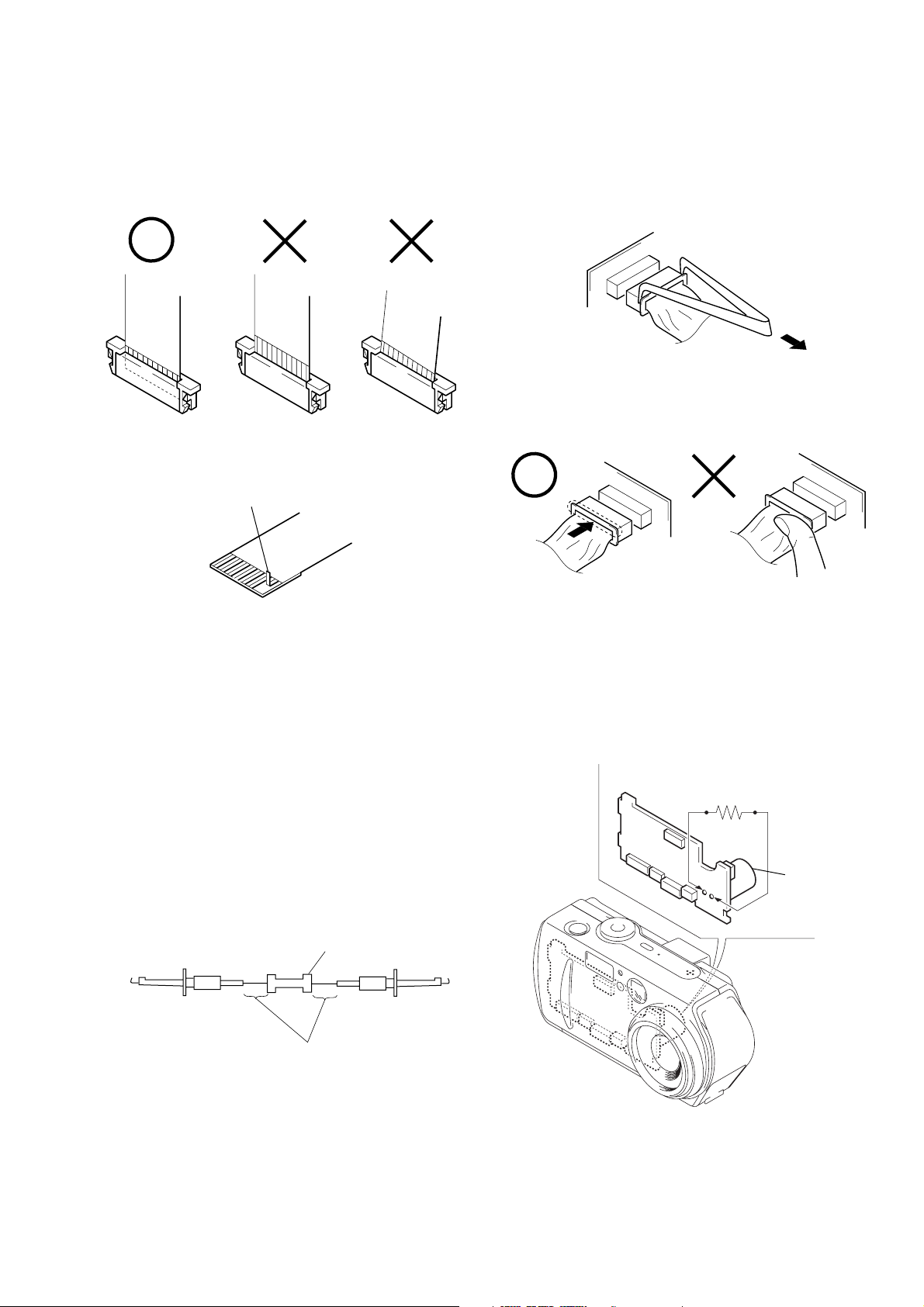
• NOTE FOR REPAIR
When installing a connector, don’t press down at wire of connector.
It is possible that a wire is snapped.
R:1 kΩ/1 W
(Part code:
1-215-869-11)
Capacitor
SERVICE NOTE
Make sure that the flat cable and flexible board are not cracked of
bent at the terminal.
Do not insert the cable insufficiently nor crookedly.
Cut and remove the part of gilt
which comes off at the point.
(Be careful or some
pieces of gilt may be left inside)
When remove a connector, don’t pull at wire of connector.
It is possible that a wire is snapped.
[Discharging of the DD-158 board’s charging capacitor
(C506)]
The charging capacitor (C506) of the DD-158 board is charged up
to the maximum 300 V potential.
There is a danger of electric shock by this high voltage when the
battery is handled by hand. The electric shock is caused by the
charged voltage which is kept without discharging when the main
power of the unit is simply turned off. Therefore, the remaining
voltage must be discharged as described below.
Preparing the Short Jig
T o preparing the short jig, a small clip is attached to each end of a
resistor of 1 kΩ /1 W (1-215-869-11).
Wrap insulating tape fully around the leads of the resistor to prevent electrical shock.
1 kΩ/1 W
Wrap insulating tape.
Discharging the Capacitor
Short-circuit between the positive and the negative terminals of
charged capacitor with the short jig about 10 seconds.
– 5 –

[Description on Self-diagnosis Display]
Self-diagnosis display
• C: ss: ss
You can reverse the camera malfunction yourself. (However , contact your Sony dealer or local
authorized Sony service facility
when you cannot recover from
the camera malfunction.)
• E: ss: ss
Contact your Sony dealer or local authorized Sony service facility.
Display Code
C:32:ss
C:13:ss
E:61:ss
E:91:ss
Countermeasure
Turn the power off and on again.
Format the “Memory stick”.
Insert a new “Memory Stick”.
Checking of lens drive circuit.
Checking of flash unit or replacement
of flash unit.
Use an “InfoLITHIUM” battery pack.
Insert a battery pack correctly. Battery pack is not inserted correctly. E:92:ss
Turn the power off and on again.
Cause
Trouble with hardware.
Unformatted memory stick is inserted.
Memory stick is broken.
When failed in the focus and zoom
initialization.
Abnormality when flash is being
charged.
Battery pack is not “InfoLITHIUM”
compatible.
Battery pack was installed or removed
when using the AC adaptor.
Caution Display During Error
SYSTEM ERROR
FORMAT ERROR
MEMORY STICK ERROR
—
– 6 –
SECTION 1
GENERAL
DSC-P30/P50
This section is extracted from
instruction manual.
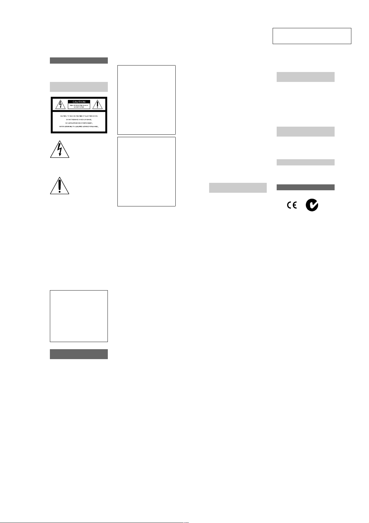
WARNING
To prevent fire or shock hazard, do
not expose the unit to rain or
moisture.
For the Customers in the
U.S.A.
This symbol is intended to
alert the user to the presence
of uninsulated “dangerous
voltage” within the
product’s enclosure that
may be of sufficient
magnitude to constitute a
risk of electric s h ock to
persons.
This symbol is intended to
alert the user to the presence
of important operating and
maintenance (servicing)
instructions in the literature
accompanying the
If you have any questions about this product,
you may call:
appliance.
Sony Customer Information Services Center
1-800-222-SONY (7669)
2
The number below is for the FCC related
matters only.
Declaration of Conformity
Trade Name: SONY
Model No.: DSC-P30
Responsible Party:Sony Electronics Inc.
Address: 680 Kinderkamack
Telephone No.: 201-930-6972
This device complies with Part 15 of the
FCC Rules. Operation is subject to the
following two conditions: (1) This
device may not cause harmful
interference, and (2) this device must
accept any interference received,
including interference that may cause
undesired operation.
Declaration of Conformity
Trade Name: SONY
Model No.: DSC-P50
Responsible Party:Sony Electronics Inc.
Address: 680 Kinderkamack
Telephone No.: 201-930-6972
This device complies with Part 15 of the
FCC Rules. Operation is subject to the
following two conditions: (1) This
device may not cause harmful
interference, and (2) this device must
accept any interference received,
including interference that may cause
undesired operation.
CAUTION
You are cautioned that any changes or
modifications not expressly approved in this
manual could void your authority to operate
this equipment.
Road, Oradell, NJ
07649 USA
Road, Oradell, NJ
07649 USA
Note:
This equipment has been tested and found to
comply with the limits for a Class B digital
device, pursuant to Part 15 of the FCC
Rules. These limits are designed to provide
reasonable protection against harmful
interference in a residential installation. This
equipment generates, uses, and can radiate
radio frequency energy and, if not installed
and used in accordance with the
instructions, may cause harmfu l interference
to radio communications. However, there is
no guarantee that interfere nce will not o ccur
in a particular installation. If this equipment
does cause harmful interference to radio or
television reception, which can be
determined by turning the equipment off and
on, the user is encouraged to try to correct
the interference by one or more of the
following measures:
— Reorient or relocate the receiving
antenna.
— Increase the separation between the
equipment and receiver.
— Connect the equipment into an outle t
on a circuit different from that to which
the receiver is connected.
— Consult the dealer or an experienced
radio/TV technician for help.
The supplied interface cable must be used
with the equipment in order to co mply with
the limits for a digital device pursuant to
Subpart B of Part 15 of FCC Rules.
For the Customers in the
U.S.A.
DISPOSAL OF LITHIUM ION
BATTERY .
LITHIUM ION BATTERY.
DISPOSE OF PROPERLY.
You can return your unwanted lithium ion
batteries to your nearest Sony Service
Center.
Note:
In some areas the disposal o f li thium ion
batteries in household or business trash may
be prohibited.
For the Sony Service Center near est yo u call
1-800-222-SONY (United States only)
Caution:
Do not handle damaged or leaking lithium
ion battery.
For the Customers in
Germany
Directive:EMC Directive 89/336/EEC,
92/31/EEC
This equipment complies with the EMC
regulations when used under the following
circumstances:
•
Residential area
•
Business district
•
Light-industry district
(This equipment complies with the EMC
standard regulations EN55022 Class B.)
Attention for the Customers in
Europe
This product has been tested and found
compliant with the limits sets out on the
EMC Directive for using connection cables
shorter than 3 meters.
Attention
The electromagnetic fields at the s pe cific
frequencies may influence the pictu re a nd
sound of this camera.
“Memory Stick”
N50
3
For the Customers in the
U.S.A. and Canada
THIS CLASS B DIGITAL DEVICE
COMPLIES WITH PART 15 OF THE
FCC RULES AND THE CANADIAN
ICES-003 OPERATION IS SUBJECT
TO THE FOLLOWING TWO
CONDITIONS:
(1) THIS DEVICE MAY NOT CAUSE
HARMFUL INTERFERENCE, AND
(2) THIS DEVICE MUST ACCEPT
ANY INTERFERENCE RECEIVED,
INCLUDING INTERFERENCE THAT
MAY CAUSE UNDESIRED
OPERATION.
Be sure to read the following
before using your camera
Trial recording
Before you record one-time events, you may
want to make a trial recording to make sure
that the camera is working correctly.
No compensation for contents of
the recording
Contents of the recording cannot be
compensated for if recording or playback is
not possible due to a malfunction of your
camera or recording medium, etc.
Notes on image data compatibility
•
This camera conforms with the Design
Rules for Camera File Systems universal
standard establ is hed by the JEITA (Japan
Electric and Information Technology
Industries). You cannot play back on your
camera still images recorded on other
equipment (DCR-TRV890E/TRV900/
TRV900E, DSC-D700, DSC-D770) that
does not conform with this universal
standard. (These models are not sold in
some areas.)
•
Playback of images recorded with your
camera on other equipment and playback
of images recorded or edited with other
equipment on your camera are not
guaranteed.
Precaution on copyright
Television programs, films, video tapes, and
other materials may be copyrighted.
Unauthorized recording of suc h ma terials
may be contrary to the provision of the
copyright laws.
Do not shake or strike the camera
In addition to malfunctions and inability to
record images, this ma y render the
“Memory Stick” unusable or image data
breakdown, damage or loss may occur.
Do not aim the camera at the sun
or other bright light
This may cause irrecoverable damage to
your eyes.
LCD screen, LCD finder (only
models with a finder) and lens
•
The LCD screen and the LCD finder are
manufactured using extremely highprecision technology so over 99.99% of
the pixels are operational for effective use.
However, there may be some tiny black
points and/or bright points (white, red,
blue or green in color) that constantly
appear on the LCD screen and the LCD
finder. These points are normal in the
manufacturing process and do not affect
the recording in any way.
•
Be careful when placing the camera near a
window or outdoors. Exposing the LCD
screen, the finder or the lens to direct
sunlight for long periods may cause
malfunctions.
Notes on batteries
Be careful when removing the b atteries, as
they may be hot after the camera is used for
long periods.
Do not get the camera wet
When taking pictures outdoors in the rain or
under similar conditions, be careful not to
get the camera wet. If moisture
condensation occurs, refer to page 71 and
follow the instructions on how to remove it
before using the camera.
Back up recommendation
To avoid the potential risk of data loss,
always copy (back up) data to a disk.
When the camera is used for long
periods
Note that the camera body may become hot.
4
5
1-1

Introduction
Checks the image after recording images
Recording still images:
page 19
Playing back still images:
page 28
Deleting images (DELETE):
page 62
Captures images with your computer
You can copy images onto your computer and view and modify images or attach
images to e-mail on your computer using the supplied USB cable and application
software.
Viewing images using a personal computer: pag e 30
Recording still images for e-mail (E-MAIL): page 48
Getting started
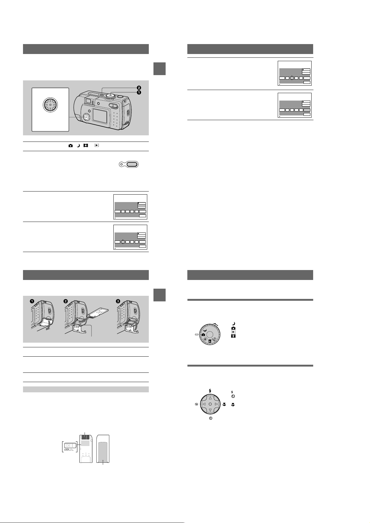
Identifying the parts
See the pages in parent hes es for details of operation.
Records a moving picture (MPEG Movie or Clip Motion)
according to your purpose
Recording moving images (MPEG
MOVIE): page 26
Selects the recording mode from various types of recordings
according to your situation
Creating Clip Motion Files: page51
Recording text documents (TEXT): page 49
Recording still images as uncompressed files (TIFF): page50
6
Attaching the str ap
Getting started
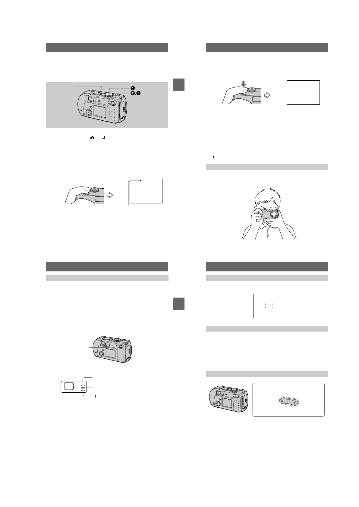
A POWER button/lamp (15)
Press and hold down this button
for approximately one second to
turn on the came ra.
B Mode dial (18) (39)
: To record in TWILIGHT
mode
: To record still images
: To playback or edit
images
: T o record moving images
or Clip Motion images
SET UP:To set the setup items
C Shutter button (19) (27)
D Flash (24)
E Photocell window for flash
Do not block while recording with
the flash.
F Self-timer (23) (27)/
AF illuminator (25)
G Lens cap (supplied)
Be sure to remove the lens cap
before recording.
H Finder window
I Beep/shutter sound holes
J Lens
K Jack cover
L USB jack (32) (34)
M VIDEO OUT jack (61)
N Tripod receptacle (bottom
surface)
Use a tripod with a screw length of
less than 5.5 mm (7/32 inch). You
will be unable to firmly secure the
camera to tripods having longer
screws, and may damage the
camera.
O RESET button (75)
8
Preparing the power supply
Installing the supplied batteries or an optional
battery pack
Your camera operates only with the following batteries.
•
Two size AA alkaline batteries (supplied)
•
“InfoLITHIUM” (S series) battery pack (NP-FS11) (not supplied)
•
Two size AA nickel metal hydride batteries (not supplied)
•
Two size AA nickel-cadmium batteries (not supplied)
The “InfoLITHIUM” ba ttery pack is recommen ded for longer operatin g times. Note
that in this Operating Instructions, “batteries” refers to siz e AA al ka lin e batteries.
Batteries
A Finder
Self-timer/recording lamp (red)
AE/AF lock lamp (gr e e n)
/CHG (flash charge/battery
charge) lamp (orange) (24)
B MENU button (40)
C DC IN jack cover (12) (14)
D DC IN jack (12) (14)
E Control button (18) (39)
F LCD screen
G DISPLAY/LCD ON/OFF button
(21)
H Zoom button (INDEX button
during playback ) ( 2 2 )
I Hook for lens cap/wrist strap
J OPEN switch
K Battery cover
L Access lamp (17)
M “Memory Stick” cover
“InfoLITHIUM” battery p ack (not supplied)
Insert the battery pack with the v mark facing toward the bat tery compartment.
Open the battery cover.
1
Open the cover while sliding the OPEN switch in the direction of the arrow.
9
10
1-2

Install the batteries.
2
Insert the two size AA batteries with the 3 and # ends facing as illustrated. Be
careful not to insert the batteries facing the wrong way.
Close the battery cover.
3
Pressing the batteries with the cover, close the cover firmly until it clicks into
place.
To remove the batteries
Open the battery cover with the battery cover side facing upward and remove the
batteries. Be careful not to drop the batteries when removing them.
Power save mode
When operating the camera with batteries, set POWER SAVE in the SET UP screen
to ON to extend the battery life. The factory setting is ON (page70).
See page 88 for more in formation on power save mode.
Auto power-off function
If you do not operate the cam era for about three minutes during recording or
playback, the camera turns off automatically to prevent wearing down the battery. To
use the camera again, pres s the P O WE R b utt on to tu rn on the camera agai n. The auto
power-off function only operates when the camera is operating using a battery pack.
The auto power-off also will not operate when playing back moving images or
playing back a slide show (page 60), or when a connector is plugged into the USB
jack or the DC IN jack.
* What is “InfoLITHIUM”?
“InfoLITHIUM” is a lithium ion battery pack which can exchange information such as battery
consumption with compatible vide o equ ipment. This unit is compatible with the
“InfoLITHIUM” battery pack (S series). “InfoLITHIUM” S series battery packs have the
mark. “InfoLITHIUM” is a trademark of Sony Corporation.
NP-FS11 battery pack (not supplied)
When you record images in an extremely cold location or using the LCD screen, the
operating time becomes short. When using the camera in an ex tremely cold location,
place the battery pack in your pocket or other place to keep it warm , t hen insert the
battery pack into the camera just before recording. When using a pocket heater, take
care not to let the heater di rectly contact the battery.
Charging the battery pack (not supplied)
You cannot charge the battery pack while your camera is turned on. Be sure to turn
Getting started
off your camera.
DC IN jack
cover
AC-LS1A AC power adaptor (not supplied)
Insert the battery pack into your camera.
1
Open the DC IN jack cover and connect the DC connecting cable to
2
the DC IN jack of your camera with the v mark facing up.
Connect the power cord (mains lead) to the AC power adaptor (not
3
supplied) and then to a wall outlet (mains).
The /CHG lamp lights up when charging begins. When the /CHG lamp goes
off, charging is completed.
Battery pack (S series)
(not supplied)
To the wall outlet (mains)
Power cord
(mains lead)
After charging the battery pack
Disconnect the AC power adaptor fr om the DC IN jack on your camera.
Battery remaining indicator
When using an optional “InfoLITHIUM” battery pack, the LCD screen on the
camera shows the rema in in g time for which you can still r ec or d or play back images.
This indication may not be ent i rely accurate depending on th e conditions of use and
the operating environment.
Charging of 10°C to 30°C (50°F to 86°F) circumstances is recommended.
When using size AA alkaline batteries, the remaining time is not shown.
Note
When you turn the LCD screen on and off, it takes about one minute for the correct battery
remaining time to appear.
Battery life and number of images that can be recorded/played back
Still image recording*
SONY alkaline batteries
(supplied)
Battery life
(min.)
Number of
images
NP-FS11 (not supplied)**
Battery life
(min.)
Number of
images
LCD screen ON Approx. 30 Approx. 600 Approx. 90 Approx. 1800
LCD screen OFF Approx. 60 Approx. 1200 Approx. 120 Approx. 2400
Still image playback***
SONY alkaline batteries
(supplied)
Battery life
(min.)
Number of
images
NP-FS11 (not supplied)**
Battery life
(min.)
Number of
images
LCD screen ON Approx. 60 Approx. 1200 Approx. 120 Approx. 2400
Approximate battery lif e and number of images that can be recorded/played ba ck
640×480 image size, standard picture quality, no flash, and in NORMAL recording
mode.
Recording at about 3-second intervals with the power save mode off (when continuous
∗
recording, the power save mode does not operate effectively.)
When using a fully charged battery pack at a temperature of 25°C (77°F).
∗∗
Playing back single images in order at about 3-sec ond intervals
∗∗∗
Moving image recording
SONY alkaline batteries
(supplied)
LCD screen
Continuous
recording
Approximate recor ding time in 160×112 imag e size.
When using a fully charged battery pack at a temperature of 25°C (77°F).
∗
Notes
•
The camera may not operate in an extremely cold location when using alkaline batteries.
Even when using an “InfoLITHIUM” battery pack (not supp l ied), the battery life and number
of images will be decreased if you use your camera at low temperatures, use the flash ,
repeatedly turn the power on/off or use the zoom.
•
The numbers of images shown on tables above are as a guide. The numbers may be smaller
depending on conditions.
•
The capacity of the “Memory Stick” is limited. The ab ove figures are a guide when you
continuously record/play back while replaci ng the “M em or y S tic k. ”
•
When LCD BACKLIGHT is set to BRIGHT, th e battery life and number of images will be
decreased.
OFF (min.)
Approx. 60 Approx. 30 Approx. 120 Approx. 90
LCD screen
ON (min.)
NP-FS11 (not supplied)*
LCD screen
OFF (min.)
LCD screen
ON (min.)
11
13
Getting started
12
Charging time
Battery pack Full charge (min.)
NP-FS11 (not supplied) Approx. 180
Approximate time to charge a completely discharged battery pack using the
AC-LS1A AC power adaptor (not supplied) a t a temperature of 25°C (77°F).
Using the AC power adaptor (not supplied)
DC IN jack
cover
To the wall outlet (mains)
Power cord
(mains lead)
AC-LS1A AC power adaptor (not supplied)
Open the DC IN jack cover and connect the DC connecting cable to
1
the DC IN jack of your camera with the v mark facing up.
Connect the power cord (mains lead) to the AC power adaptor (not
2
supplied) and then to a wall outlet (mains).
Using a car battery
Use Sony DC adaptor/charger (not supplied).
Using your camera abroad
For details, see page74.
When using the AC power adaptor
Be sure to use it near the wall outlet. If a malfunction occurs, disconnect the plug
from the wall outlet.
14
1-3
Setting the date and time
When you first use your camera, set the date and time. If these are not set, the
CLOCK SET screen appear s whenever you turn on your camera.
Control button
Select the item with
, then set with
vVbB
the center z.
Set the mode dial to , , or
1
Press and hold down the POWER button for
2
approximately one second to turn on the
power.
The POWER ON/OFF (CHG) lamp (green) lights
up.
The CLOCK SET screen appears on the LCD
screen.
To change the date and time, set the mode dial to
SET UP (page 69) and perform th e procedure from step 3.
Select the desired date display format with
3
on the control button, then press the
v/V
center z.
Select from [Y/M/D] (year/month/da y), [M/D/Y]
(month/day/year) or [D/M/Y] (day/month/year).
Select the year, month, day, hour or minute
4
item you wa nt to se t w it h b/B on the control
button.
The item to be set is indicated with v/V.
CLOCK SET
2001
OK
CLOCK SET
2001
OK
/:/
/:/
POWER
ON/OFF(CHG)
1
12 00
1
1
12 00
1
Y / M / D
M / D / Y
D / M / Y
AM
CANCEL
Y / M / D
M / D / Y
D / M / Y
AM
CANCEL
Set the numeric value with v/V on the
5
control button, then press the center z to
enter it.
Getting started
OK
OK
After entering the number, v/V moves to the next
item.
If you selected [D/M/Y] in step 3, set the time on a
24-hour cycle.
Select [OK] with B on the control button,
6
then press the center z at the desired
moment to begin clock movement.
The date and time are entered.
To cancel the date and time setting
Select [CANCEL] with v/V/b/B on the control button, then press the center z.
Note
If the rechargeable button battery is ever fully discharged (page 72), the CLOCK SET screen will
appear again. When this happens, rese t th e da te and time by starting from step 3 above.
CLOCK SET
2001
OK
CLOCK SET
2001
OK
/:/
/:/
Y / M / D
M / D / Y
D / M / Y
OK
1
12 00
7
AM
CANCEL
Y / M / D
M / D / Y
D / M / Y
OK
4
10 30
7
PM
CANCEL
Inserting the “Memory Stick”
Access lamp
Open the “Memory Stick” cover.
1
Insert the “Memory Stick.”
2
Insert the “Memory Stick” with the B mark facing toward the battery
compartment as illustrated until it clicks.
Close the “Memory Stick” cover.
3
Removing the “Memory Stick”
Open the “Memory Stick” cover, then press the “Memory Stick” once lightly.
Notes
•
Insert the “Memory Stick” firmly until it clicks, otherwise a message such as “MEMORY
STICK ERROR” will be displayed.
•
Never remove the “Memory Stick” or turn off the power while the access lamp is lit up.
•
Y ou can not record or edi t images o n a “Mem ory Stick” if the erasure prevention switch is set to
the LOCK position.
Connector
15
Getting started
16
Basic operations
Recording
B
Basic operations
How to use the mode dial
The mode dial switches the function which is used for recording, playback, or
editing. Set the dial as follows before starting to operate your camera.
: To record still images in TWIL IGHT mode
: To record still images
: To play back or ed it images
: To record moving images or Clip Motion images
SET UP: To display the setup items (The SET UP pos ition
changes the settings of infrequently-used
items.)
How to use the control button
When the menu is not displ ayed, the control button is used to pe rform the following
operations.
(v): Recording with flash
(V): Recording with self-timer
7
(b): Checkin g the last recorded image
(B): Recording close subjects
When you select above functions with the control button while recording with the
LCD screen turned off, the LCD screen lights for approximatel y 2 seconds and the
selected function icon appears on the screen. The LC D screen also lights
automatically when the MENU button is pressed, but in this case the LCD screen
does not turn off automatically.
Erasure
prevention
switch
The position and shape of the erasure prevention switch may differ depending on the type s of
“Memory Stick” used.
Label space
17
18
1-4
Recording still images
Still images are recorded in JPEG format.
Before recording still images, press the POWER button to turn on the power and
insert a “Memory Stick.”
POWER
Set the mode dial to or .
1
Press and hold the shutter button halfway down.
2
The image freezes momentarily, but is not yet recorded. While the AE/AF lock
indicator z is flashing, the camera automatically adj us ts the exposure and
focus of the captured imag e. When the camera finishes the automatic
adjustments, the AE/AF lock indicator z stops flashing, then light s up and the
camera is ready for recording.*
If you release the shut ter button, the record ing will be canceled.
AE/AF lock indicator (green) flashes t lights up
BB
B
B
Recording
Press the shutter button fully down.
3
The shutter sounds.
“RECORDING” appears on the LCD screen, and the image will be recorded on
the “Memory Stick.” When “RECORDING” disappears, you can record the
next image.
RCORI
If the flashing AE/AF lock indicator changes to flashing slowly, the subject may be difficult to
∗
focus on (dark, poor contrast) or the subject may be extrem el y cl ose . Re le as e th e shu tte r
button, then focus again.
The number of images you can record on a “Memory Stick”
See pages 46 and 48 to 52.
Notes
•
When recording a bright subject, the LCD screen color may change after AE/AF lock, but this
does not affect the recorded imag e.
•
When you press the shutter button fully down at once in step 2, the camera starts recording
after the automatic adjustment is complete. However, the recording cannot be carried out while
the /CHG lamp (page 21) is flashing. (During this time, the camera is charging the flash.)
Holding the camera correctly
Hold the camera so that yo ur fingers do not block the flash and do not t ouc h the lens
portion when recording images.
19
Recording images with the finder
You can extend the battery time by turning off the LCD screen and recording using
the finder.
Each time you press DISPLAY/LCD ON/OFF, the status of the LCD screen changes
as follows:
See page 85 for a detailed description of the indicated items.
The LCD backlight is turned on.
(All the available indicators are turned on.)
r
The LCD backlight is turned on.
(Warning messages are turned on.)
r
The LCD backlight is turned off.
DISPLAY/LCD ON/OFF
Indicators in the finder
Notes
•
You cannot check the entire recording range with the finder. Recording with the LCD screen is
recommended when it is necessary to correctly unde r sta nd the recording range.
•
Because of the difference of the portion of the finder and lens, use the LCD screen whe n you
record a subject closer than 1 m (3 1/4 feet).
•
When [DEMO] is set to [ON] in the S ET UP sett i ngs, yo u c ann ot tur n off the LCD screen once
the demonstration starts.
•
You cannot turn off the LCD backlight when setting in SET UP and when displaying the menu.
•
You cannot turn off the self-timer indicators and some of the indicators used in advanced
operations.
•
The indicators on the LCD screen are not recorded.
Recording lamp (red)
AE/AF lock lamp (green)
/CHG lamp (orange)
BB
B
B
Recording
20
Recording with the LCD screen
When recording w it h the LCD screen, align the AF frame in the center of the screen
with the subject.
AF frame
Checking the last recorded image (Quick Review)
You can check the last recorded image by clearing the menu from the screen
(page 40) and pressing b (7) on the control b utton. (You can perform this operation
even when the LCD screen is off.)
To return to the norma l recording mode: press lightly on the shutter button or
press b (7) again.
To delete the image: 1. Press MENU. 2. Select [DELETE] with B on the control
button, then press the center z. 3. Select [OK] with v on the control button, then
press the center z.
Using the zoom feature
Zoom button
W side: for wide-angle (subject appears
farther away)
T side: for telephoto (subject appears closer)
If you cannot get a sharp focus on a close subject
Press the zoom W button repeatedly and move closer to the subject until the focus is
sharp.
Minimum focal distance to the subject
W side: About 25cm (9 27/32 inches) or more
T side: About 80 cm (31 1/2 i n ches) or more
To record even closer subjects, see page 53.
21
22
1-5
Digital zoom function
VING IMA
GE:
This camera has a digital zoom function.
Digital zoom enlarges the image by digital processing and it starts to function when
zoom exceeds 3×.
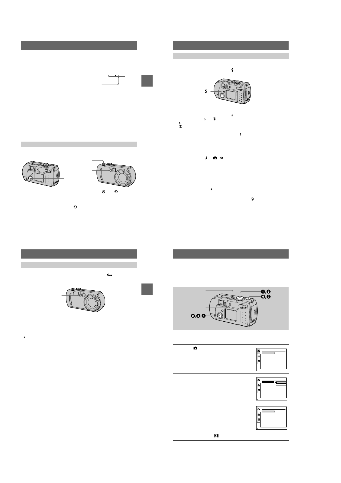
Recording images with the flash
The factory setting is auto (no indicator). In this mode, the flash automatically
strobes when the surroundings is dark. To change the flash mode, clear the menu
(page 40), then press the
indicator appears on the LCD screen.
control button v (
) repeatedly so that the flash mode
The T side of the bar shows the
digital zooming zone.
Using digital zoom
•
The maximum zoom magnification is 6×.
•
Digital zooming dete ri or at es the picture quality. When digital zoom is not
necessary, set [DIGITA L ZOOM] to [OFF] in the setup settings (page 69).
Notes
•
Digital zoom does not work for moving images.
•
Use the LCD screen when using digital zoom function. Digitally zoomed images do not appear
in the finder.
•
The AF frame (page85) does not appear on the LCD screen.
Using the self-timer
When you use the self-timer function, the subject is recorded about 10 seconds after
you press the shutte r butt on.
Shutter button
Self-timer lamp
Control button
Clear the menu (page 40), then press the control button V ( ). The (self-timer)
indicator appears on t he LCD scre en, an d about 10 seco nds afte r you pr ess the s hutter
button, the subject is re corded. The self-timer lamp flashes an d t he beep sounds after
you press the shutter button until the shutter is released. To cancel the self-timer
recording, press the control button V ( ) again.
23
BB
B
B
Recording
Control button v ()
Each time you press the control button v ( ), the indicator changes a s follows.
(No indicator) t t t (No indicator)
Forced flash: The flash strobes regardless of the surrounding brightness.
No flash: The flash does not strobe.
You can change the brightness of the flash with [ ±] (FLASH LEVEL) in the menu
settings (page 42).
To reduce the red-eye phenomenon
Set [RED EYE REDUCTION] to [ON] in the setup settings, the flash strobes before
recording to reduce the red-eye phenomenon (page 69). When [ON] is selected and
the mode dial is set to or , appears on the LCD screen.
Notes
•
When [ISO] is set to [AUTO] in the menu settings, the recommended shooting distance using
the built-in flash is 0.3 m to 2.0 m (11 13/16 inches to 6 feet 6 3/4 inches). When it is not set to
[AUTO], the flash may be ineffective even if the flash level is changed.
•
Red-eye reduction may not produce the desired effects depending on individual differences, the
distance to the subject, if the subject does not see the pre-strobe, or other conditions.
•
The flash effect is not obtained easily when you use forced flash in a bright locat ion.
•
While charging the flash, the /CHG lamp flashes. After the charging is complete, the lamp
goes out.
•
The flash does not function when recording moving images (excludi ng C lip Motion).
•
When you record images i n a dark place with the camer a set to
becomes slow, so using a tripod is recommended to prevent shaking.
(no flash), the shutter speed
24
Recording images with the AF illuminator
The AF illuminator is fill light to focus on a subject easi ly und er dark conditions. Set
[AF ILLUMINATOR] (page 69) to [ON] in the setup settings, appears on the
LCD screen and the AF illuminator emits light when the shutter button is pressed
halfway. It keeps emitting light until the focus is locked.
AF illuminator
Notes
•
If AF illuminator light does not reach the subject sufficiently or the subj ect ha s no c ontr a st,
focus will not be achieved. (Approximate distance up to 2.0 m (6 feet 6 3/4 inches) is
recommended.)
•
In TWILIGHT mode (page 47), the AF illuminator will emit only when the flash mode is set to
(Forced flash).
•
Focus is achieved as long as AF illuminator light reaches to the subje ct even if its light is
slightly out of the middle position of the subje c t.
•
The AF illuminator is a very bright light. Although it is safe to use, avoid shining it directly into
someone’s eyes at a close distance.
BB
B
B
Recording
Recording moving images
Moving images are reco rded in MPEG format ( page 38).
To recor d moving images, press the POWER button to turn on the power and in sert a
“Memory Stick.”
DISPLAY/LCD ON/OFF
1
2
3
4
5
POWER
Set the mode dial to SET UP.
Select [ ] (CAMERA) with v/V on the
control button, then press B.
Select [MOVING IMAGE] with v/V on the
control button, then press B.
Select [MPEG MOVIE] with v/V on the
control button, then press the center z.
Set the mode dial to .
CAMERA
MOVING IMAGE:
DATE/TIME:
DIGITAL ZOOM:
RED EYE REDUCTION:
AF ILLUMINATOR:
PAGE SELECT
CAMERA
MOMOVING IMA
DATE/TIME:
DIGITAL ZOOM:
RED EYE REDUCTION:
AF ILLUMINATOR:
OK
CAMERA
MOVING IMAGE:
DATE/TIME:
DIGITAL ZOOM:
RED EYE REDUCTION:
AF ILLUMINATOR:
PAGE SELECT
MPEG MOVIE
OFF
OFF
OFF
ON
GE:
MPEG MOVIE
CLIP MOTION
MPEG MOVIE
OFF
OFF
OFF
ON
25
26
1-6
Press the shutter button fully down.
FILE BACK/NEXT
10:30
PM
2001 7 4100-0028
6/8
640
6
“REC” appears on the LCD screen, and the image is recorded on the “Memory
Stick.”
Sound cannot be recorded with moving images.
Press the shutter button fully down again to stop recording.
7
The recording stops. Or, the recording stops when the “Memory Stick” is full.
For details on the image size, see “Setting the image size (IMAGE SIZE)” on
page 45”.
Using the self-timer
When you use the self-timer function, the subject is recorded about 10 seconds after
you press the shutte r butt on.
Clear the menu (page 40), then press the control button V ( ). The (self-timer)
indicator appears on the LCD screen, and the recording starts about 10 seconds after
you press the shutter button. The self-timer lamp flashes and the beep sounds after
you press the shutter button until the shutter is released. To stop the self-timer
recording, press the control button V ( ) again.
LCD screen indicators during recording
Each time you press DSPL /LCD ON/OFF, the status of t he LCD screen changes as
follows: all indi cators on t indicators off t LCD screen off.
These indicators are not recorded. See page 86 for a detailed description of the
indicators.
Note
If you remove the battery or otherwise turn off the power partway through a recording, the
moving image recorded thus far is not saved. When the battery low mark E appears while
operating the camera with batt er ies, stop the recording at this poi nt be fo re the batteries
completely run out.
BB
B
B
Recording
Playback
B
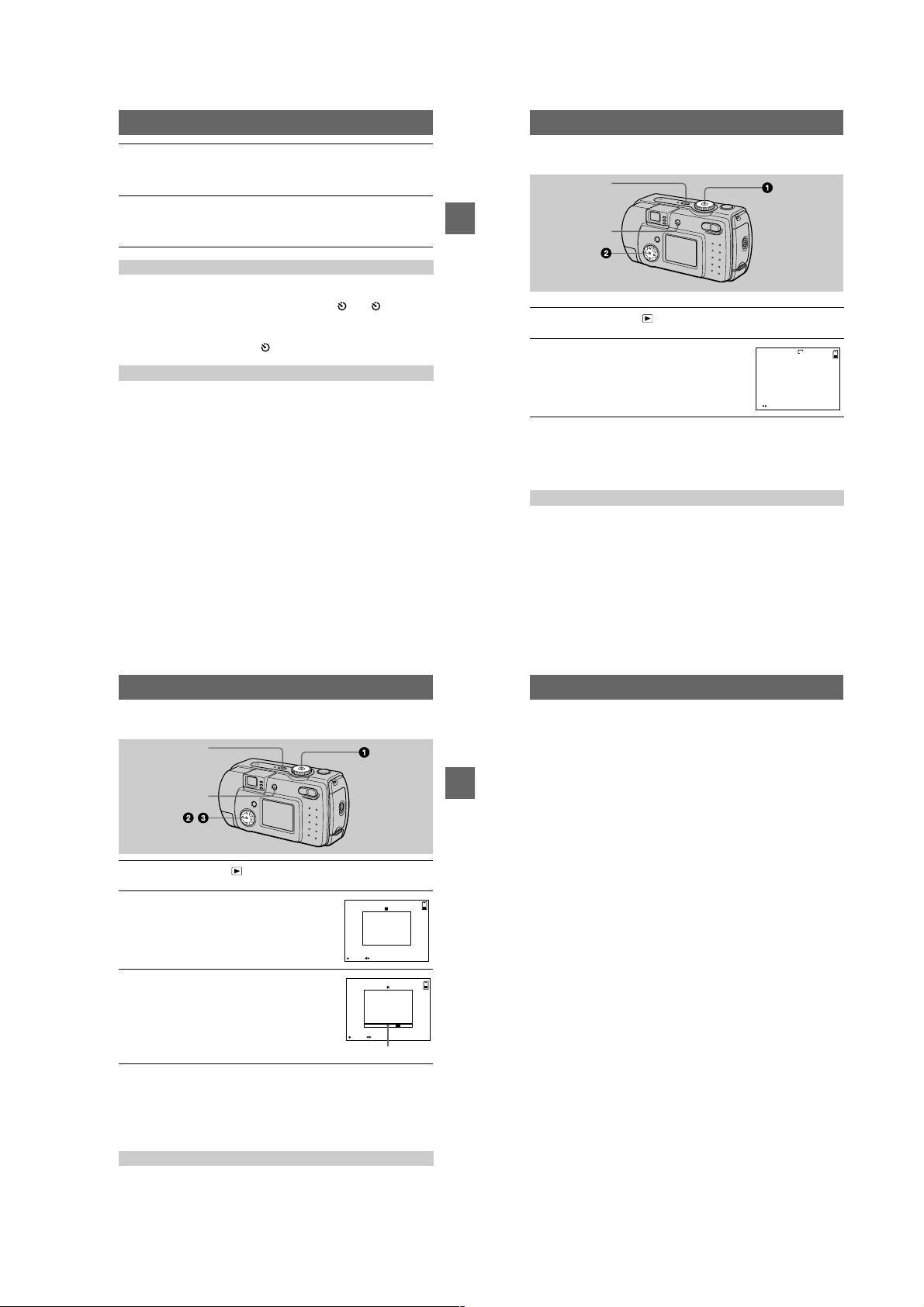
Playing back still images
DISPLAY/LCD ON/OFF
1
2
Notes
•
•
Each time you press DSPL/LCD ON/OFF, the statu s of the LCD screen changes as
follows: all indicators on t indicators off t LCD screen off.
See page 87 for a detailed description of the indicators.
POWER
Set the mode dial to .
The last recorded image (still or moving) appears on th e LC D screen.
Select the desired still image with the
control button b/B.
: To display the preceding image.
b
: To display the next image.
B
You might not be able to correctly pl ay b ack images reco rded with this camera on other
equipment.
You cannot play back on this camera images larger than the maximum image size that can be
recorded with this camera.
LCD screen indicators during still image playback
Playing back moving images
DISPLAY/LCD ON/OFF
1
2
3
To pause playback
Press the center z on the control button to stop the pl ayback.
To advance or rewind the moving image
Press the control button b/B during playback.
To return to the normal playback, press the center z on the control button.
LCD screen indicators during moving image playback
Each time you press DSPL /LCD ON/OFF, the status of t he LCD screen changes as
follows: all indi cators on t indicators off t LCD screen off.
See page 87 for a detailed descr i pt i on of the indicators.
POWER
,
Set the mode dial to .
The last recorded image (still or moving) appears on the LCD screen.
Select the desired moving image with the
control button b/B.
Moving images are display ed one-size smaller than
still images.
: To display the preceding image.
b
: To display the next image.
B
Select the center z to start the playback.
The moving image is played back.
During playback , B (playback) appears on the LCD
screen.
To advance or rewind, press the control button b/B
during playback .
FILE BACK/NEXTPLAY
STOP REV/CUE
Playback bar
2001 7 4MOV 00001 10:30 PM
6/8
6/8
27
29
28
Viewing images using a personal
computer
You can view data recorded with your camera on a personal computer, modify and
attach it to e-mail using application software. This section describes the method for
viewing images on a personal computer using the supplied USB cable.
There are two ways to make the USB connection, which are the norma l co nnection
BB
B
B
Playback
and the PTP connection (page 70). This is set using [USB CONNECT] in the setup
settings. However, any OS does not conform to [PTP] as of M ar ch, 2001. Here
describes the way using the [NORMAL] setting.
The factory setting of USB mode is [NORMAL].
The mode can be checked and set as follows.
1
Set the mode dial to SET UP.
2
Select [SETUP2] with v/V, then press B.
3
Select [USB CONNECT] with v/V, then press B.
4
Select the connection mode with v/V.
The USB cable is used to connect the camera to a personal computer so that
operations can be performed on image files recorded in a “Memory Stick” from the
personal computer.
In order to use the USB cable, a USB driver must be installed in the personal
computer beforehand.
Be sure to also refer to the operation manuals for your personal computer and the
application soft w a r e .
Notes
•
Data recorded with your camera is stored in the following formats. Make sure that applications
that support these file formats are installed on your per sona l computer.
— Still images (other than TEXT mode, uncompressed mode and Clip Motion): JPEG format
— Moving images: MPEG format
— Uncompressed mode still images: TIFF format
— TEXT mode/Clip Motion: GIF format
•
Depending on your application software, the file size may increase when you open a still image
file.
•
When you copy the image to the camera from your comp u ter, which was modified with a
retouching software and was converted to another file format, the “FILE ERROR” message
may appear and you may be unable to open the image.
•
Depending on your application software, only the first frame of the Clip Mot ion file may be
played back.
Communications with your computer (for Windows only)
Communications between your camera and your computer may not recover after recovering
from Suspend or Sleep.
•
When connecting the camera to a computer, use a fully charged “InfoLITHIUM” battery pack
(not supplied) or the AC power adapter (not supplied). Do not use batteries.
30
1-7
Recommended computer en vironment
Recommended Windows environment
OS: Microsoft Windows 98 , Windows 98SE, Windows 2000 Professional, Windows
Millennium Edition
The above OS is required to be instal led at the factory .
Operation is not assured in an environment upgraded to the operating sy ste ms described
above.
CPU: MMX Pentium 200 MHz or faster
The USB connector must be provided as standard.
Recommended Macintosh environment
Macintosh computer with the Mac OS 8.5.1/8.6/9.0/9.1 standard installation
However, note that the update to Mac OS 9.0/9.1 should be used for the following models.
•
iMac with the Mac OS 8.6 factory pre-installed and a slot loa ding type CD-ROM drive
•
iBook or Power Mac G4 with the Mac OS 8.6 factory pre - inst a lle d
The USB connector must be provided as standard.
QuickTime 3.0 or newer must be installed (to play back moving pictures).
Notes
•
If you connect two or more USB equipment to a single persona l co mputer at the same time,
some equipment may not operate depending on the type of USB eq uipment.
•
Operations are not guaranteed when using a hub.
•
Operations are not guaranteed for all the recommended computer environments menti o n ed
above.
•
Microsoft and Windows are either registered trademarks or trademarks of Microsoft
Corporation in the United States and /or oth er countries.
•
Macintosh and Mac OS, QuickTime are either registered trademarks or trademarks of Apple
Computer, Inc.
•
All other product names mentioned herein may be the tra de ma r ks or register ed trade marks of
their respective companies. Furthermore, “™” and “®” are not mentioned in each case in this
manual
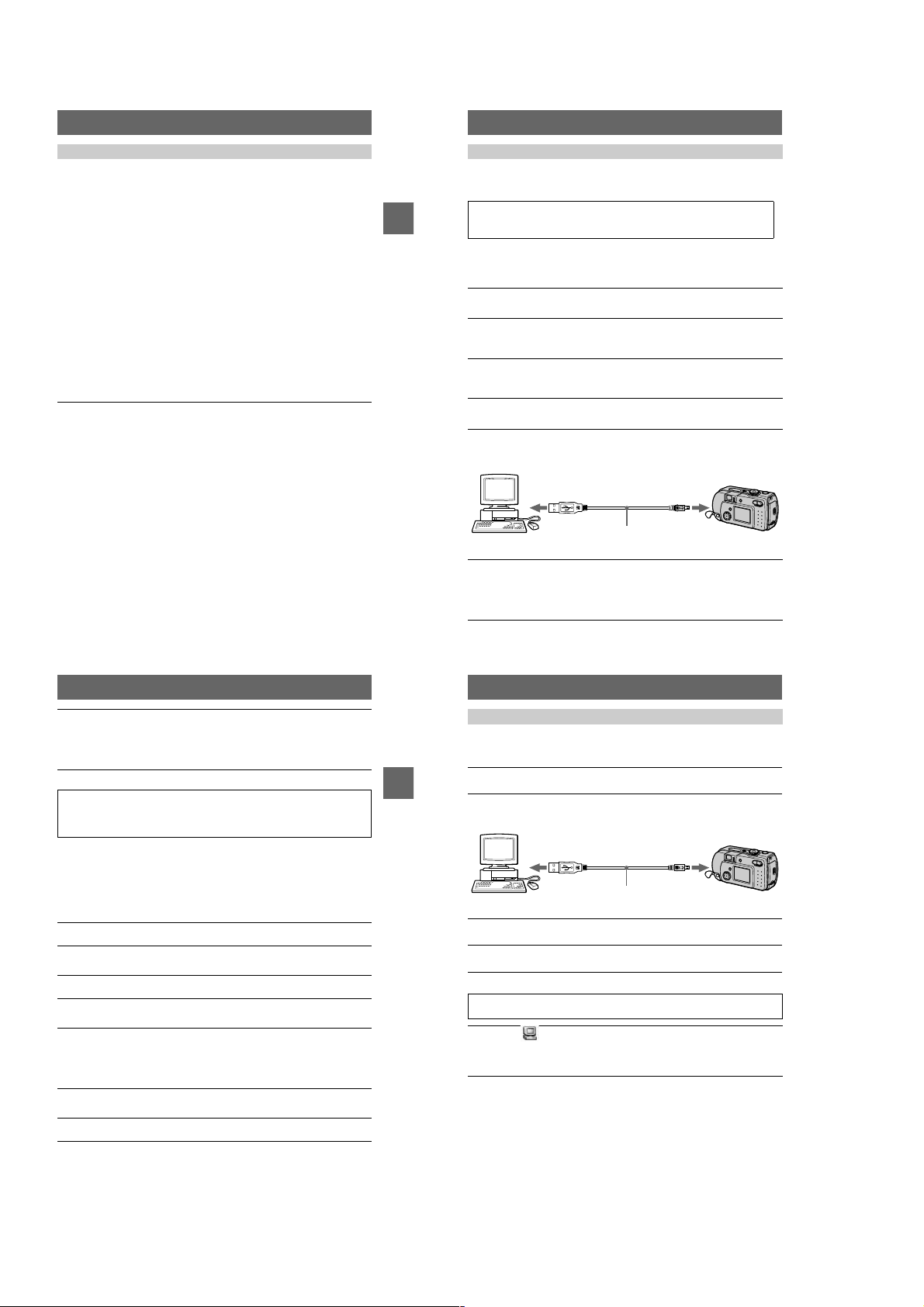
Installing the USB driver
Before connecting your camera to your personal computer, install the USB driver to
the computer. The USB driver is included with the application software in the CDROM which is supplied with your camera.
Be sure to complete installation of the USB driver before connecting the
USB cable. If you connect the USB cable first, you will be unable to
BB
B
B
Playback
install the USB driver properly.
See page 80 for corrective measures if the USB cable was connected before installing
the driver and the driver software could not be ins ta ll ed correctly.
For Windows 98/98SE/Me and Windows 2000 users
Turn on your personal computer and allow Windows to load.
1
Do not connect the USB cable in this step.
Insert the supplied CD-ROM in the CD-ROM drive of your personal
2
computer.
The application software sc r een appears.
Click “USB Driver Installation for Windows 98/98SE/Me and
3
Windows 2000”.
USB driver installation starts.
Follow the on-screen messages to install the USB driver.
4
Your personal computer may restart.
Connect the USB jack (mini-B) on your camera with the USB
5
connector on your personal computer using the supplied USB
cable.
USB cable
to the USB ja ck
(mini-B)
Push the
connector in as
far as it will go.
to the USB connector
Personal computer
Insert a “Memory Stick” into your camera, connect the AC power
6
adaptor and turn on your camera.
“USB MODE” appears on the LCD screen of your camera and the camer a is set
to communication standby mode. Your personal computer recognizes the
camera, and the Windows Add Hardware Wizard starts.
31
Follow the on-screen messages to have the Add Hardware Wizard
7
recognize the hardware.
The Add Hardware Wizard starts twice because two different USB dr ivers are
to be installed. Be sure to allo w the i nstallatio n to complet e without inte rrupting
it.
Notes
•
Do not connect the USB cable bef or e the USB driver installation is completed in step 4.
•
In step 7, make sure that a “Memory Stick” is inserted into your camera before installing the
USB driver. Otherwise, you will be unable to install the USB driver.
For Macintosh users
• When using MacO S9.1
It is not necessary to install the USB driver. The Macintosh recognizes the camera as
a drive simply by connecting it to the Macintosh with the USB cable.
• When using MacOS8.5.1/8.6/9.0
Follow the procedures below to install the driver.
Turn on your personal computer and allow the Mac OS to load.
1
Insert the supplied CD-ROM in the CD-ROM drive of your personal
2
computer.
Double-click the CD-ROM drive icon to open the window.
3
Double-click the icon of the hard disk containing the OS to open
4
the window.
Move the following two files from the window opened in step 3 to
5
the “System Folder” icon in the window opened in step 4 (drag
and drop) .
•
Sony USB Driver
•
Sony USB Shim
When “Put these items into the Ex te nsions folder?” appears, click
6
“OK.”
Restart your personal computer.
7
32
Viewing images
When viewing moving images on a Windows system, RealPlayer, Windows Media
Player or other moving ima ge playba ck applic ations must be in stalled . When v ie wing
moving images on a Macintosh system, QuickTime3.0 or later must be installed.
Turn on the power of your personal computer and allow Windows
1
or Mac OS to load.
BB
B
B
Playback
Connect the USB jack (mini-B) on the camera with the USB
2
connector on your personal computer using the supplied USB
cable.
to the USB connector
Personal computer
Insert a “Memory Stick” into your camera, and connect the AC
3
power adaptor to your camera and then to a wall outlet (mai ns) .
Turn on the power of your camera.
4
“USB MODE” appears on the LCD screen of th e camera.
USB cable
to the USB ja ck
(mini-B)
Push the
connector in as
far as it will go.
For Windows 98/98SE/Me and Windows 2000 users
Open “ My Computer” on Windows and double click the newly
5
recognized drive. (Example: “Removable Disk (E:)”)
The folders inside the “Memory Stick ” are displayed.
If the drive is not recognized, see “Troubleshooting” on page 75.
33
34
1-8
Select and double-click the desired image file from the folder.
6
For the detailed folder and file name, see “Image file storage destinations a nd
image files” on page 37.
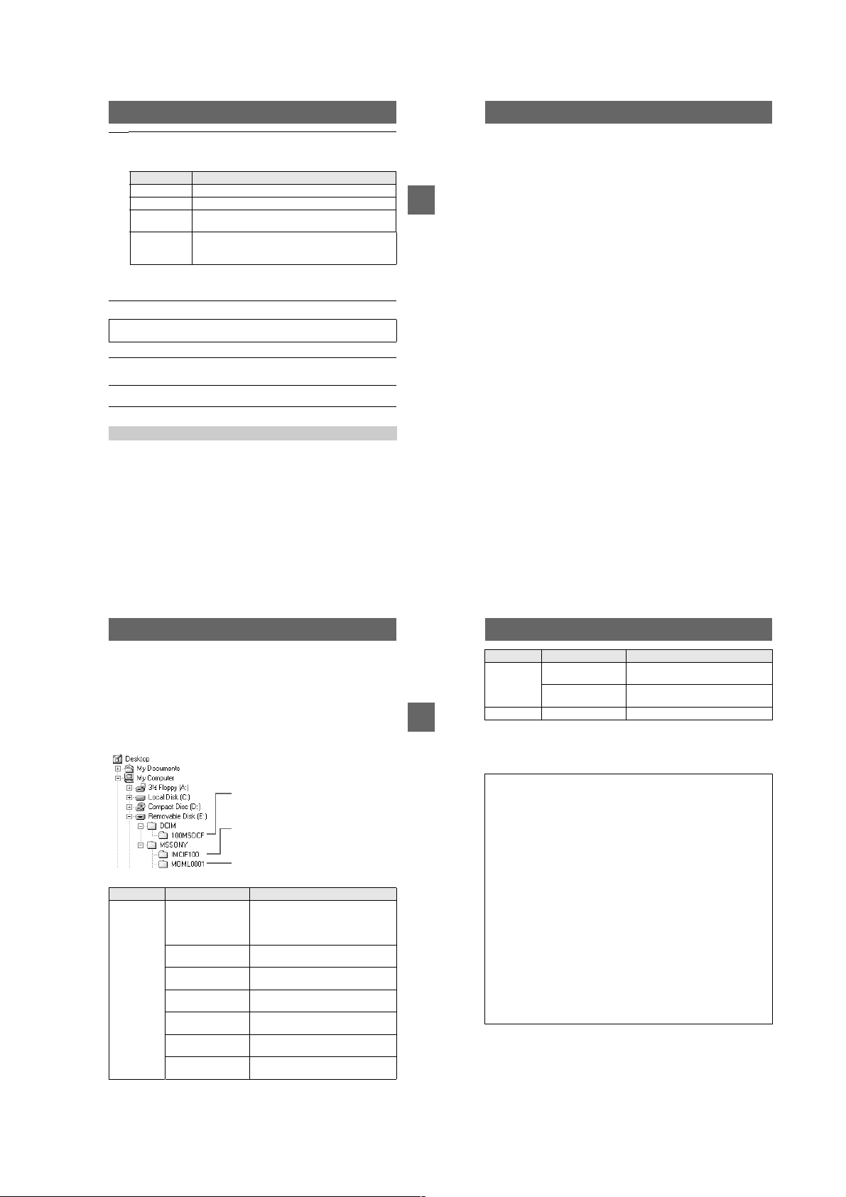
Desired file type Double-click in this order
Still image “Dcim” foldert“100msdcf” foldertImage file
Moving image* “Mssony” foldert“Moml0001” foldertImage file*
Clip Motion
image
E-mail image
TIFF image
(uncompressed)
Copying a file to the hard disk of your personal computer befor e v iewing it is
∗
recommended. If you play back the file directly from the “Memory Stick”, the image
may break off.
“Dcim” foldert“100msdcf” foldertImage file
“Mssony” folder t“Imcif100” fold ertImage file
For Macintosh users
Follow the procedure 1 – 4 on page 34.
Double click the newly recognized icon on the desktop.
5
The folders inside the “Memory Stick” are displayed.
Select and double-click the desired image file from the folder.
6
Notes on using your personal computer
“Memory Stick”
•
Operation is not guaranteed if you are using a “Memory St ic k” that was formatted with a
personal computer, or if you used a personal computer to format the “Memory Stick” in your
camera through a USB connection.
•
Do not optimize the “Memory Stick” on a Windows machine. This will shorte n the “Memory
Stick” life.
•
Do not compress the data on the “Memory Stick.” Compressed files cannot be played back on
your camera.
For Windows Me and Windows 2000 u sers
The following procedures are recommended when disconnecting the USB cable from
your personal computer or ejecting the “Memory Stick” from the camera while it is
connected to your pers onal computer.
1
Stop the drive by clicking on the “Unplug/Eject” icon in the task tray.
2
When the message appear s confirming the safe removal of the hardware,
BB
B
B
Playback
disconnect the USB cable or eject the “Memory Stick”.
Software
•
Depending on your application software, the file size may increase when you open a still image
file.
•
When you load an image modified using the supplied retouch software from your personal
computer to the camera or when you directly modify the image on the camera, the image
format will differ so the “FILE ERROR” message may appear and you may be unable to ope n
the file.
•
Depending on your application software, only the first frame of the Clip Mot ion file may be
played back.
Communications with your personal computer (for Windows
only)
Communications between your camera and your personal computer may not recover after
recovering from Suspend, Resume, or Sleep.
35
Image file storage destinations and
image files
Image files recorded with y our camera are grouped in fold ers by recording mode.
The meanings of the file names are as follows.
within the range from 0001 to 9999.
For Windows Me users (The drive recognizing the camer a is
“E.”)
Folder containing still im age, TEXT mode image
and Clip Motion image data
Folder containing E-MAIL mo de and TIFF mode
image data
Folder containing movi ng image data
Folder File Meaning
100MSDCF DSC0
CLP0
CLP0
MBL0
MBL0
TXT0
TXT0
.JPG•Still image file recorded normally
ssss
ssss
ssss
ssss
ssss
ssss
ssss
•
.GIF•Clip Motion file recorded in NORMAL
.THM•Index image file of Clip Motion file
.GIF•Clip Motion file recorded in MOBILE
.THM•Index image file of Clip Motion file
.GIF•Still image file recorded in TEXT mode
.THM•Index image file of still image file
stands for any number
ssss
Still image file recorded in
– E-MAIL mode (page 48)
– TIFF mode (page 50)
mode (page51)
recorded in NORMA L m ode
mode (page51)
recorded in MOBILE m ode
(page 49)
recorded in TEXT mode
36
Folder File Meaning
IMCIF100 DSC0
DSC0
MOML0001 MOV0
BB
B
B
Playback
The numerical portions of the following files are the same.
– A small-size image file recorded in E-MAIL mode and its corresponding image file
– An uncompressed image file recorded in TIFF mode and its corresponding image file
– An image file recorded in TEXT mode and its corresponding index image file
– An image file recorded with Clip Motion and its corresponding index image file
Tips
The digital still camera saves recorded images as digital data. The format of the
saved data is called as the file format. The formats that can be used with this
camera are as follows:
JPEG format
Most digital still cameras, operating systems of computers, and browser
software adopt this format. This format is able to compress files without
appreciable deterioration. However, if the image is compressed and saved on
repeated occasions, the image will dete riorate. This camera records still images
using the JPEG format for normal recording.
GIF format
Using this format, the image will not deteriorat e ev en if the image is compressed
and saved on repeated occasions. This format limits the number of colors to
256 colors. This camera records still images using the GIF format in Clip
Motion (page51) or TEXT mode (page49).
TIFF format
Stores shooting images without compression, so the image does not deteriorate.
Most of operating systems and applications correspond to this format. This
camera records still images using the TIFF format for the TIFF mode (page 50).
MPEG format
This format is very typical for moving images. This camera records moving
images using the MPEG format.
.JPG•Small-size image file r ecorded in
ssss
ssss
ssss
E-MAIL mode (page 48)
.TIF•Uncompressed image file recorded in
TIFF mode (page 50)
.MPG•Moving image file recorded normally
37
38
1-9

Advanced operations
Before performing advanced
operations
This section describes the basic control methods that are frequently used for
“Advanced operations.”
How to use the mode dial
The mode dial switches the function which is used for recording, playback, or
editing. Set the dial as follows before starting to operate your camera.
: To record still images in TWILIGHT mode
: To record still images
: To play back or edit images
: To record moving images or Clip Motion
images
SET UP: To display the setup items (The SET UP
position changes the se ttings of infrequentlyused items.)
How to use the control button
When the menu or setup screen is displayed, the control button is used to select the
buttons, images and menu item s displayed on the LCD screen of your camera and
modify the settings. The operation methods that are frequently used for “Advanced
operations” are described below.
Turning on/off the operation buttons (menu) on the LCD screen
Press MENU to display/
clear the menu on the
LCD screen.
0
EV
Menu
0
WB
ISO
You can perform this operation even when the LCD screen is off.
Setting up the items in the setup or menu
Set the mode dial to SET UP so that the
Before performing advanced operations
1
setup screen appears, or press MENU so
that the menu appears.
When the mode dial is set to SET UP or :
2
1
Press v/V/b/B on the control button to select the item you want to set up.
2
Press the center z on the control button to enter the item.
When the mode dial is set to , , or :
Press v/V/b/B on the control button to select the
setting of the item.
The selected setting is turned to yellow, and the
setup is complete.
CAMERA
MOVING IMAGE:
DATE/TIME:
DIGITAL ZOOM:
RED EYE REDUCTION:
AF ILLUMINATOR:
SELECT
MPEG MOVIE
OFF
ON
OFF
ON
00
200
100
O
Menu settings
Menu items that can be modified differ depending on the positions of th e mode dial.
The LCD screen shows only the items you can operate at the mo m ent. Factory
settings are indicated w ith x.
When the mode dial is set to /
Item Setting Description
EV +2.0EV to
9
(FOCUS)
WB
(WHITE
BAL)
(SPOT
METER)
ISO 400
(IMAGE
SIZE)
(P. QUALITY)
–2.0EV
(infinite)
∞
7.0 m
3.0 m
1.0 m
0.5 m
AUTO
x
HOLD
AUTO
x
IN DOOR
OUT DOOR
ON
OFF
x
200
100
AUTO
x
1600×1200
x
(DSC-P50)
1280×960
x
(DSC-P30)
1600 (3:2)
(DSC-P50)
1280(3:2)
(DSC-P30)
1024×768
640×480
FINE Records still images in the fine image quality
x
STANDARD Records still images in the standard image
Adjust the exposure value (page 53).
Sets the distance to the subject (page 52).
Sets the white balance (pag e 5 4) .
Measures the brightness of the spot to be
recorded (page 57).
Selects the ISO film speed. When recording
under dark situations or recording a fast-moving
subject, use a high-number setting. When you
record high-quality images, use a low-number
setting (except when the mode dial i s se t to ).
Selects the image size when recording still
images (page 45).
mode.
quality mode.
39
40
Item Setting Description
MODE
(REC
MODE)
±
(FLASH
LEVEL)
PFX
(P. EFFECT)
Before performing advanced operations
(
SHARPNESS
When the mode dial is set to (MOVING IMAGE is set to
MPEG MOVIE in the setup se ttings.)
EV +2.0EV to
9
(FOCUS)
WB
(WHITE
BAL)
(SPOT
METER)
TIFF Records a TIFF (uncompr essed) file in addition
to the JPEG file (page 50).
TEXT Records a GIF file in black-a nd-white (page 49).
E-MAIL Records a small-size (320×24 0) JPEG file in
NORMAL Records an image using the normal recording
x
addition to the selected image size (page 48).
mode.
HIGH Makes the fl as h level higher than normal.
NORMAL Normal setting.
x
LOW Makes the flash level lower than normal.
x
)+2+1
x
SOLARIZE
B&W
SEPIA
NEG.ART
OFF
0
–1
–2
Sets the image special effects (page 55).
Adjusts the sharpnes s of the image.
The indicator appears (e xcept when the
setting is 0).
Item Setting Description
–2.0EV
(infinite)
∞
7.0 m
3.0 m
1.0 m
0.5 m
AUTO
x
HOLD
AUTO
x
IN DOOR
OUT DOOR
ON
OFF
x
Adjust the exposure value (page 53).
Sets the distance to the subject (page 52).
Sets the white balance (page 54).
Measures the brightness of the spot to be
recorded (page57).
41
42
1-10

Item Setting Description
(IMAGE
SIZE)
PFX
(P. EFFECT)
When the mode dial is set to (MOVING IMAGE is set to CLIP
MOTION in the setup settings.)
EV +2.0EV to
9
(FOCUS)
WB
(WHITE
BAL)
(SPOT
METER)
(IMAGE
SIZE)
±
(FLASH
LEVEL)
PFX
(P. EFFECT)
320×240
160×112
x
SOLARIZE
B&W
SEPIA
NEG.ART
OFF
x
Item Setting Description
–2.0EV
(infinite)
∞
7.0 m
3.0 m
1.0 m
0.5 m
AUTO
x
HOLD
AUTO
x
IN DOOR
OUT DOOR
ON
OFF
x
NORMAL
x
MOBILE
HIGH Makes the flash level higher than normal.
NORMAL Normal setting.
x
LOW Makes the flash level lower than norm al .
SOLARIZE
B&W
SEPIA
NEG.ART
OFF
x
Selects the MPEG image s iz e w hen recording
moving images (page 45).
Sets the image special effects (page 55).
Adjust the exposure value (page 53).
Sets the distance to the subject (page 52).
Sets the white balance (page 5 4).
Measures the brightness of the spot to be
recorded (page 57).
Selects the Clip Motion image size (page 45,
51).
Sets the image special effects (page 55).
Item Setting Description
(
SHARPNESS
When the mode dial is set to
DELETE OK Deletes the displayed image (page 62).
PROTECT – Protect s images against accidental era sure
PRINT – Marks the print mark on still images (page 66).
SLIDE*
Before performing advanced operations
RESIZE* 1600×1200
ROTA TE*
DIVIDE OK
Only in single-image mode.
∗
+2
)
+1
0
x
–1
–2
Item Setting Description
CANCEL Cancels deleting of the image.
INTERVAL
REPEAT
START Starts the slide show.
CANCEL Cancels the slide show.
(DSC-P50)
1280×960
(DSC-P30)
1024×768
640×480
CANCEL
OK
CANCEL
CANCEL
Adjusts the sharpnes s of the image.
The indicator appears (except w hen the
setting is 0).
(page 63).
Sets the slide show interval.
3 sec/5 sec/10 sec/30 sec/1 m i n
x
ON/OFF
x
Changes the recorded image size (page65).
Rotates the still image (page 61).
Divides an moving image (page 67).
Setting the image size (IMAGE SIZE)
Set the mode dial to , or
1
Press MENU.
2
The menu appears.
Select the desired image size from [ ] (IMAGE SIZE) and press
3
.
v/V
Still image sizes:
DSC-P50
1600×1200, 1600 (3:2 )*, 1024×768, 640×480
DSC-P30
1280×960, 1280(3:2)* , 1024×768, 640×480
The image is recorded in the ratio of three to two to fit the printing paper size. Using this
∗
image size, the margin of an image is not printed out. However, the slight amount of the
upper and lower black portions are displayed on the LCD screen.
Moving image (MPEG movie) sizes:
320×240, 160×112
Clip Motion sizes:
NORMAL (160×120), MOBILE (80×72)
.
43
44
The number of images* or the time** that you can record on a “Memory
Stick” (4 MB)
Image size
1600×1200 (DSC-P50) Approx. 7 Approx. 3 –
1600 (3:2) (DSC-P50) Approx. 7 A pprox. 3 –
1280×960 (DSC-P30) Approx. 11 Approx. 6 –
1280 (3:2) (DSC-P30) Appr ox. 11 Approx. 6 –
1024×768 Approx. 16 Approx. 10 –
640×480 Approx. 57 Approx. 23 –
320×240 ––
160×112 ––
MOBILE (80×72) ––Approx. 200
Before performing advanced operations
NORMAL (160×120)*** ––Approx. 20
When MODE (REC MODE) is set to NORMAL.
∗
The maximum recording time in continuous rec o rd ing
∗∗
When recording 10 frames per Clip Motion file.
∗∗∗
Remaining num ber of reco rdable images (p age 85)
The remaining number of recordable im ages i s a guide lin e for when MODE (R EC MODE) is set
to NORMAL. The actual number of remaining images may differ depending on the recording
conditions.
Tips
The size of the image is indicated by the pixel unit. The higher the number of pixels, the more
information is included. So , a n image that is saved using a large number of pixels is suitable
for a large-format print and one that is saved using a smaller number of pixels is suitable for
attaching to an E-mail. Normally, an image is recorded in the ratio of four to three to fit the
monitor ratio. This ca mera can also record the image in the ratio of three t o two to
accommodate the most common printing paper size. This is the same ratio as the one used in
photo-developing shops.
Quality
STANDARD FINE
Moving image
Approx. 40 sec.
Approx. 160 sec.
45
1600×1200 (4:3) 1600 (3: 2)
46
1-11
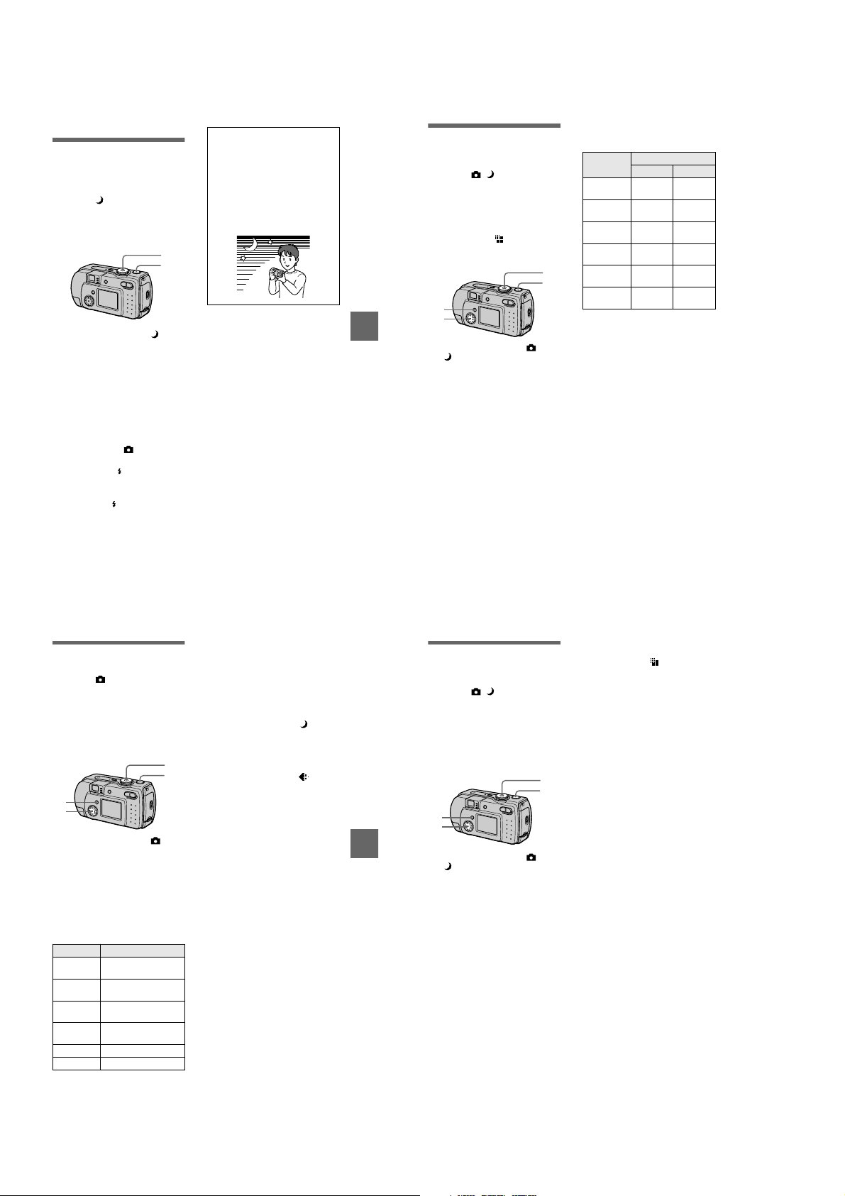
Various recording
B
Records images
according to shooting
conditions (TWILIGHT
mode)
Mode dial:
This camera has a preset TWILIGHT
mode. This m o de is suitable for the
night scene.
1
2
1
Set the mode dial to .
Allows you to record bright
subjects in dark places without
losing the dark atmosphere of the
surroundings. The shutter speed
becomes slower, so we
recommend that you use a tri pod
to prevent shaking.
2
Record the image.
To cancel the TWILIGHT
mode
Set the mode dial to .
Notes
•
Set the forced flash whe n you use the
flash in the TWILIGHT mode.
•
When using the TWILIGHT mode, the AF
illuminator (page 25) emits when the flash
mode is set to the forced flash mode.
•
You cannot record moving images in the
TWILIGHT mode.
Tips
Under normal recording conditions, the
camera automatically makes various
adjustments, such as those for the focus,
iris, exposure, and white balance, as it
shoots. However, you may not be able to
carry out your desired shooting
depending on shooting conditions. The
TWILIGHT mode provides you with
near-optimum adjustments to suit your
shooting situation.
BB
B
B
Various recording
Recording still
images for e-mail
(E-MAIL)
Mode dial: /
In the E-MAIL mode, a small-size
image which is suitable for e-mail
transmission is also recorded at the
same time as recording a normal still
image. (The size of the normal still
image is set using [ ] (IMAGE
SIZE) in the menu settings (page 45).)
1
4
2
3
1
Set the mode dial to or
.
2
Press MENU.
The menu appears.
3
Select [MODE] (REC MODE)
with b/B, [E-MAIL] with v/V.
4
Record the image.
The number of images that you can
record on a “Memory Stick” (4 MB)
in E-MAIL mode
Image size
1600×1200
(DSC-P50)
1600 (3:2)
(DSC-P50)
1280×960
(DSC-P30)
1280 (3:2)
(DSC-P30)
1024×768
640×480
Remaining number of recordable
images (page 85)
The actual number of remaining images
may differ depending on the recording
conditions.
To return to normal
recording mode
Select [NORMAL] with v/V in step 3.
Quality
STD FINE
Approx. 7 Approx. 3
Approx. 7 Approx. 3
Approx. 10Approx.
Approx. 10Approx.
Approx. 15Approx.
Approx. 46Approx.
5
5
9
21
Recording text
documents (TEXT)
Mode dial:
The TEXT mode is suitable for
recording a document to emphasize its
character by the black and white
colors. The LCD screen also turns to
black and white, and the i m age is
recorded in the GIF format.
1
4
2
3
1
Set the mode dial to .
2
Press MENU.
The menu appears.
3
Select [MODE] (REC MODE)
with b/B, [TEXT] with v/V.
4
Record the image.
The number of images that you can
record on a “Memory Stick” (4 MB)
in TEXT mode*
Image size Number of images
1600×1200
(DSC-P50)
1600 (3:2)
(DSC-P50)
1280×960
(DSC-P30)
1280 (3:2)
(DSC-P30)
1024×768 Minimum 26
640×480 Minimum 59
The maximum number of recordable
∗
images depends on the document
condition, such as the amount of text
portions.
Minimum 12
Minimum 13
Minimum 18
Minimum 20
47
To return to normal
recording mode
Select [NORMAL] with v/V in step 3.
Notes
•
If the subject is not evenly illuminated, you
may be unable to record a clear image.
•
Writing and reading data take more time
than normal recording.
•
When the mode dial is set to , images
can be recorded, but the image may be
bleached out or may be turned black.
•
Remaining number of recordable images is
not displayed.
•
The number of recordable images is the
same regardless of whether [ ]
(P. QUALITY) is set to STANDARD or
FINE.
49
BB
B
B
Various recording
48
Recording still images
as uncompressed
files (TIFF)
Mode dial: /
Records the images without
compression, so the image does not
deteriorate. Image s recorded in this
mode are suitable for printing with a
high-quality image. The JP EG
(compressed) format image is also
recorded with the TIFF format image.
1
4
2
3
1
Set the mode dial to or
.
2
Press MENU.
The menu appears.
3
Select [MODE] (REC MODE)
with b/B, [TIFF] with v/V.
4
Record the image.
The number of images that you
can record on a “Memory Stick”
(8 MB) in TIFF mode is approx. 1.
To return to normal
recording mode
Select [NORMAL] with v/V in step 3.
50
Notes
•
JPEG images are recorded in the image
size selected by the [ ] (IMAGE SIZE)
menu (page 45). TIFF images are recorded
in [1600×1200] (DSC-P50) or [1280×960]
(DSC-P30) size other than when [1600
(3:2)] (DSC-P50) or [1280 (3:2)]
(DSC-P30) is selected.
•
Writing data takes more time than in
normal recording.
•
The supplied “Memory Stick” (4 MB)
does not have sufficient capacity to record
uncompressed images.
1-12

Creating Clip Motion
Files
Mode dial:
Clip Motion is an animation function
that plays back still images in
succession. The images are stored in
GIF format, which is convenient for
creating home pages or attaching
images to an e-mail.
1,3
6,7
4
2,5,8
1
Set the mode dial to SET UP.
The setup screen appe ar s.
2
Select [ ] (CAMERA) with
, [MOVING IMAGE] with
v/V
, [CLIP MOTION] with
B/v/V
, then press z.
v/V
3
Set the mode dial to .
4
Press MENU.
The menu appears.
5
Select [ ] (IMAGE SIZE)
with b/B, the desired mode
with v/V.
NORMAL (160×120)
Clip Motion of up to 10 frames can
be recorded. This is suitable for
use on home pages, etc.
MOBILE (80×72)
Clip Motion of up to 2 frames can
be recorded. This is suitable for
use with portable data terminals.
6
Record the image for the fir st
frame.
60
min
MAKING "CLIP MOTION"
Before carrying out step 8, the
images are temporarily stored in
memory. These images are not
recorded on the “Memory Stick”,
yet.
7
Record the image f or the ne xt
frame.
Image recording can be repeated
up to the maximum number of
recordable frames.
8
Press z.
All the frame images are recorded
on the “Memory Stick”.
To delete some or all the
frame images while making
a Clip Motion recording
1
Press the control button b (7) in
step 6 or 7.
The recorded frame images are
played back in turn and stop at the
last image.
2
Press MENU, and select [DELETE
LAST] or [DELETE ALL], then
press z.
3
Select [OK], then press z.
When [DELETE LAST] is selected
in step 2, each time you repeat
step 3, the recorded frame is
deleted from the newest one.
BB
B
B
Various recording
The number of Clip Motion frames
that you can record on a “Memory
Stick” (4 MB)
Image size
NORMAL (160×120)
MOBILE (80×72) Approx. 200
When recording 10 frames per Clip
∗
Motion file
Notes
•
You cannot change the image size partway
through a Clip Motion recording.
•
Reading and writing data take more time
than normal image recording.
•
Due to the limitations of th e G IF format,
the number of colors for Clip Motion
images is reduced to 256 colors or less.
Therefore, the picture quality may
deteriorate for some images.
•
The file size is redu ced in MOBILE mode,
so the picture quality deteriorates.
•
GIF files not created on this camer a ma y
not be displayed correctly.
•
All the frame images are immediately
recorded on the “Memory Stick” if the
mode dial is switched or the power is
turned off.
Number of
images
Approx. 20*
Setting the distance
to the subject
Mode dial: /
Normally the focus is automatically
adjusted. This function is useful when
the auto focus does not work well such
as in dark places.
/
1
2
3
1
Set the mode dial to ,
or .
2
Press MENU.
The menu appears.
3
Select [9] (FOCUS) with
, the desired distance
b/B
setting with v/V.
You can select from the fol l owin g
6 focus settings:
AUTO, 0.5 m (1 3/4 feet), 1.0 m
(3 1/4 feet), 3.0 m (9 3/4 feet),
7.0m (23feet), ∞ (infinite).
To reactivate auto focusing
Select [AUTO] with v/V in step 3.
Notes
•
Focal point information may not
completely show the correct distance. Use
the information as a guide.
•
If you shoot a subject within 0.5 m
(1 3/4 feet) while the zoom is set to th e T
side, you cannot get a clear focus. In such
cases, the focal point information flas h es .
Press the zoom W button until the
indicator stops flashing.
Recording images in
macro
Mode dial: / /
The macro recording is used when
zooming up a little subject, such as
flowers, insects.
1
2
3
1
Set the mode dial to ,
or .
2
Clear the menu, and press
the control button B ().
The (m acro) indicator appears
on the LCD screen.
You can record a subject as cl ose
as about 3 cm (1 3/16 inches) from
the lens surface with the zo om set
all the way to the W side, or about
80 cm (31 1/2 inches) wi th the
zoom set all the way to the T side.
To return to normal
recordin g mo de
Press the control button B ( ) again.
The indicator disappears.
Note
When recording images in macro, use the
LCD screen. If you record using the finder,
the range visible in the finder may differ
from the actual recording range.
51
Adjusting the
exposure
(EXPOSURE)
Mode dial: / /
Adjusts the exposure v alue wh ich is set
in the automatic adjustment.
1
2
3
1
Set the mode dial to ,
.
or
2
Press MENU.
The menu appears.
3
Select [ ] (EV) with b/B, the
desired exposure value with
.
v/V
Adjust the exposure value while
checking the brightness of the
background.
Y ou can select values ranging from
+2.0 EV to –2.0 EV in steps of 1/3
EV.
Note
If a subject is under extremely bright or dark
situations, or the flash is use d, the exposure
adjustment may not be effective.
53
BB
B
B
Various recording
52
Tips
Normally, the camera automatically
adjusts the exposure. If the color of the
image is too dark or bright as illustrated
below, we recommend that you adjust the
exposure manually. When recording a
backlighted subject or a subject in the
snow, set it toward +, and when recording
a dark subject with fully displayed on the
LCD screen, set it toward –.
Set the exposure
toward +
Set the exposure
–
toward
54
Adjusting the white
balance (WHITE
BALANCE)
Mode dial: / /
Normally, the white balance is
automatically adjusted (AUTO). When
you record with the shooting condition
fixed or under the specific lighting
condition, you can manually adjust the
white balance.
1
2
3
1
Set the mode dial to ,
or .
2
Press MENU.
The menu appears.
3
Select [WB] (WHITE BAL)
with b/B, the desired setting
with v/V.
HOLD
Recording a single-colored subject
or background
AUTO (No indicator)
Adjusts the white balance
automatically
Under fluorescent lighting
IN DOOR (n)
•
Places where the lighting
condition changes quickly
•
Under bright lighting such as
photography studios
•
Under sodium or mercury lamps
OUT DOOR ( )
Recording a sunrise/sunse t, night
scene, neon signs, or fireworks
1-13
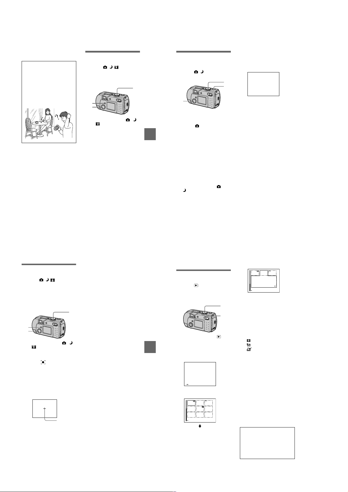
To reactivate auto adjustment
Select [AUTO] with v/V in step 3.
Tips
The image is susceptible to lighting
conditions. The image looks blue under
sunlight in the summer, and looks red
under mercury lamps. Human eyes can
resolve these problems. However, the
camera cannot resolve the pro b le m
without making adjustments. Normally,
the camera adjusts it automatically, but, if
the image appears in stran ge colors, we
recommend that you change the white
balance mode.
Enjoying picture
effects (P. EFFECT)
Mode dial: / /
You can digitally process images to
obtain special effect.
2
3
1
Set the mode dial to ,
or .
2
Press MENU.
The menu appears.
3
Select [PFX] (P . EFFECT) with
, the desired mode with
b/B
.
v/V
SOLARIZE
The light contrast is clearer and the
picture looks like an illustration.
B&W
The picture is mono chrome (black
and white).
SEPIA
The picture is sepia-toned like a n
old photograph.
NEG.ART
The color and brightness of the
picture are reversed as in a
negative.
OFF
Does not use the picture effect
function.
To cancel picture effect
Select [OFF] with v/V in step 3.
5
Record the image.
Recording the date
and time on the still
image (DATE/TIME)
Mode dial: /
1,4
1
5
2,3
1
Set the mode dial to SET UP.
The setup screen appears.
2
Select [ ] (CAMERA) with
, [DATE/TIME] with B/v/V,
v/V
then press B.
3
BB
B
B
Various recording
Select the date and time
setting with v/V, then press
.
z
DAY & TIME
Imposes the date, hour, and
minute.
DATE
Imposes the year, month, and day.
OFF
Does not impose the date and time.
4
Set the mode dial to or
.
The date and time do not appear on
the LCD screen during shooting.
These appear during play ba ck
only.
2001
Notes
•
If you select [DATE] in step 3, the date is
imposed onto the image in the order
selected with “Setting the date and time”
(page 15).
•
The date and time are not superimposed
onto moving images or Clip Motion
images.
Using the spot lightmetering function
Mode dial: / /
Use this function when there is
backlight or when there is strong
contrast between the subject and the
background, etc. Position the point you
want to record on the spot lightmetering cross hair.
1
2
3
1
Set the mode dial to ,
or .
2
Press MENU.
The menu appears.
3
Select [ ] (SPOT METER)
with b/B, [ON] with v/V.
Position the point you want to
record at the spot light-metering
cross hair.
Record the picture wh en the
automatic adjustment has been
completed.
LCD screen
Spot lightmetering
cross hair
To cancel the spot lightmetering function
Select [OFF] with v/V in step 3.
55
57
BB
B
B
Various recording
56
Various playback
B
Playing back three or
nine images at once
Mode dial:
Y ou can display mult iple images on the
LCD screen at one time using the
zoom buttons.
1
2
1
Set the mode dial to .
2
Press the zoom W button
repeatedly.
The LCD screen display changes
as follows:
•
Single (single-image) scree n
10:30
PM
2001 7 4100-0001
FILE BACK/NEXT
•
Index (nine-image ) screen
CLIP TEXT
SINGLE DISPLAY
58
•
Triple-image screen
APERTURE VALUE :
F2.2
SHUTTER SPEED :
1/125
+0.0
EXPOSURE VALUE :
CLIP TEXT
10:30
PM
2001 7 4100-0005
SINGLE DISPLAY
The image indicated by the yellow
frame in the index screen is
displayed in the middle of the
triple-image screen with the
recording informati on. To display
the other information, press the
control button v/V.
The following marks ar e displa yed
on each image according to th e
image type and settings.
: Moving image file
: E-mail file
: Print mark
: Protect mark
-
TEXT: TEXT file
TIFF: TIFF file
CLIP: Clip Motion file
(No mark): Normal recording (no
settings)
To display the next
(previous) index screen
Press the control button v/V/b/B.
To return to n ormal playback
(single-image)
•
Press the zoom T button repeated ly.
•
Press the control button z.
Note
When viewing an image recorded in Clip
Motion or TEXT mode on the index screen,
the image may appear different from the
actual image.
Tips
When the triple-image screen is displayed,
pressing MENU opens the menu includi ng
[PRINT], [PROTECT], and [DELETE].
For details on these items, see pages 62,
63, or 66. T o cl ose t he menu, press MEN U
again. The menu disappears and the
recording information is indicated.
1-14

Enlarging a part of
the still image (Zoom
and trimming)
Mode dial:
2,4
1
Set the mode dial to .
2
Display the image to be
enlarged.
3
Zoom in/out the image with
the zoom T/W buttons.
4
Press the control button
repeatedly to select the
desired portion of the image.
: The image moves downward
v
: The image moves upward
V
: The image moves rightward
b
: The image moves leftward
B
To return to the normal size
Press the control button z.
To record an enlarged image
(trimming)
1
Press MENU after zooming.
2
Select [TRIMMING] with B, then
press z.
3
Select the image size with v/V,
then press z.
The image is recorded and the
image on the LCD screen returns
to the normal size after recording.
Notes
•
You cannot zoom moving images.
•
Y ou can zoom images recorded in TEXT
mode, but cannot trim them.
•
Zoom scaling is up to 5× regardless of the
original image size.
•
The quality of enlarged images may be
deteriorated.
•
The original data is left even if you enlarge
1
the image.
•
The enlarged image is recorded as the
newest file.
3
•
If you trim an image, the remaining
“Memory Stick” capacity will be
decreased.
•
If the remaining “Memory Stick” capacity
is not sufficient, you may be unable to trim
an image.
•
You cannot trim to an image of 3:2.
To stop the SLIDE SHOW
Playing back the still
images in order
(SLIDE)
Mode dial:
This function is useful for checking the
recorded images or for presentations,
etc.
2
3,4
1
Set the mode dial to .
2
Press MENU.
BB
B
B
Various playback
The menu appears.
3
Select [SLIDE], then press z.
Set the following items.
INTERVAL
You can select from 1 min ( one
minute), 30 sec (30 second s),
10 sec (10 seconds), 5sec
(5 seconds), or 3sec (3 seconds).
REPEAT
ON: Plays back images in a
continuous loop.
OFF: After all images have been
played back, the slide show end s.
4
Select [START], then press
.
z
The slide show begins.
To cancel the SLIDE SHOW
setting
Select [CANCEL] with v/V in step 3,
then press z.
playback
Press z, select [EXIT] with B, then
press z.
To skip to the next/previous
image during the SLIDE
SHOW
Select b/B at the lower-left on the
LCD screen, then press z.
1
Note
The interval setting time may vary
depending on the image size.
Rotating a still image
(ROTATE)
Mode dial:
You can rotate the image recorded in
portrait orientation and display it in
landscape orient at ion.
2
3,4
1
Set the mode dial to , and
display the i mage to rotate.
2
Press MENU.
The menu appears.
3
Select [ROTATE] with
then press z.
4
Rotate the image clockwise
or counterclockwise ,
select [OK] with v/
press z.
To cancel rotation
Select [CANCEL] with v/V in step 4,
then press z.
Notes
•
You cannot rotate protected or
uncompressed images, or images recorded
in TEXT mode.
•
You may not be able to rotate images
recorded with other equipment.
•
Also, when viewing images on a com puter ,
the image rotation information may not be
reflected depending on the applicati on
software.
,
b/B
then
,
V
Viewing images on a
TV screen
Mode dial:
Before connecting you r ca mera, be
sure to turn off the TV.
Set the TV/VIDEO
1
switch to “VIDEO”.
VIDEO connecting cable
1
Connect the VIDEO
connecting cable to the
VIDEO OUT jack of your
camera and to the video
input jacks of the TV.
2
T urn on the TV and start
playback on your camera.
The playback image appears on
the TV screen.
Notes
•
You cannot use a TV that has an antenna
(aerial) connector only.
•
When viewing a still image on the TV, the
black band may appear around the image.
(supplied)
to VIDEO OUT
jack
59
60
Editing
B
Deleting images
(DELETE)
Mode dial:
You can delete unwant ed files.
In single-image or tripleimage mode
3
2,4,5
1
Set the mode dial to .
2
BB
B
B
Various playback
In single-i m age mode:
Display the image you want to
delete with b/B.
In triple-image mode:
Press the zoom W button twice to
turn to the triple-image mode.
Display the image you want to
delete with b/B.
3
Press MENU.
The menu appears.
4
Select [DELETE] with b/B in
single-image mode, or with
in triple-image mode,
v/V
then press z.
5
Select [OK] with v/V, then
press z.
The image (or the middlepositioned image in triple-image
mode) is deleted.
1
W
In index mode
2
3,4,5
1
Set the mode dial to , then
display the index screen with
the zoom W button.
2
Press MENU.
The menu appears.
3
Select [DELETE] with b/B,
then press z.
4
Select [ALL] or [SELECT]
with b/B, then press z.
5
When you select [ALL]
Select [ENTER] with b/B, then
press z.
All the unprotected images are
deleted.
When you select [SELECT]
1
Select the images to be deleted
with the control button, then
press z.
To cancel, press z again.
Repeat this step to sele ct other
images.
The (delete) indicator
appears on the selected images.
MENU
SET TO NEXT
2
Press MENU.
3
Select [OK] with b/B, then
press z.
1
W
61
62
1-15

To cancel deleting
Select [CANCEL] with b/B in step 4
or [EXIT] with b/B in step 5, then
press z.
Note
If there are files on the “Memory Stic k” with
names having the same last 4 digits as the
file name of the image to be deleted, the se
files are also deleted at the same time.
Preventing accidental
erasure (PROTECT)
Mode dial:
Protects images again st accidental
erasure.
In single-image or tripleimage mode
1
W
3
2,4
1
Set the mode dial to .
2
In single-i m age mode
Display the image you want to
protect with b/B.
In triple-image mode
Press the zoom W button twice to
turn to the triple-image mode.
Display the image you want to
protect with b/B.
3
Press MENU.
The menu appears.
4
Select [PROTECT] with b/B
in single-image mode, or with
in triple-image mode,
v/V
then press z.
The displayed image (or the
middle-positioned image in tripleimage mode) is protected .
The - indicator appears on the
image.
To release protection
Press z again in step 4. - indicator
disappears.
BB
B
B
Editing
In index mode
2
3,4,5
1
Set the mode dial to , then
display the index screen with
the zoom W button.
2
Press MENU.
The menu appears.
3
Select [PROTECT] with b/B,
then press z.
4
Select [ALL] or [SELECT]
with b/B, then press z.
5
When you select [ALL]
Select [ON] with b/B, then press
.
z
All the images in the “Memory
Stick” are protected.
When you select [SELECT]
The frame of the selected image
turns green.
1
Select the images to be
protected with the control
button, then press z.
To cancel, press z again.
Repeat this step to select other
images.
The - indicator appears on
the selected images.
-
MENU
SET TO NEXT
2
Press MENU.
3
Select [OK] with b/B, then
press z.
To release protection
1
If you selected [ALL] in step 4, select
[OFF] then press z. If you selected
W
[SELECT] in step 4, select the images
to be unprotected with the cont r ol
button. Select [OK] with b/B, then
press z.
To cancel protection
Select [CANCE L ] with b/B in step 4
or [EXIT] with b/B in step 5, then
press z.
Changing the
recorded still image
size (RESIZE)
Mode dial:
You can change the image size of the
recorded image.
2
3,4
1
Set the mode dial to , then
display the i mage of which
you want to change the size.
2
Press MENU.
The menu appears.
3
Select [RESIZE] with b/B,
then press z.
4
Select the desired size with
, then press z.
v/V
DSC-P50:
1600×1200, 1024×768, 640×480
DSC-P30:
1280×960, 1024×768, 640×480
The resized image is recorded.
To cancel changing the size
Select [CANCEL] with v/V in step 4,
then press z.
Notes
•
The original image is retained even after
resizing.
•
Y ou can n ot change the size of images
recorded in TEXT mode, moving images,
uncompressed images, or Clip Motion
images.
•
The resized image is recorded as the
newest file.
•
If you resize an image, the remaining
“Memory Stick” capacity will be
decreased.
1
•
When you change from a small size to a
large size, the picture quality deteriorates.
•
If the remaining “Memory Stick” capacity
is not sufficient, you may not be able to
resize an image.
•
You cannot resize to an image of 3:2.
63
65
BB
B
B
Editing
64
Selecting still images
to print (PRINT)
Mode dial:
You can mark a print mark on still
images recorded with your camera.
This mark is convenient when you
have images printed at a shop that
conforms with the DPOF (Digital Print
Order Format) standard .
.
In single-image or tripleimage mode
1
W
3
2,4
1
Set the mode dial to .
2
In single-i m age mode
Display the image you want to
print with b/B.
In triple-image mode
Press the zoom W button twice to
turn to the triple-image mode.
Display the image you want to
print with b/B.
3
Press MENU.
The menu appears.
4
Select [PRINT] with b/B in
single-image mode, or with
in triple-image mode,
v/V
then press z.
The (print) mark is mark ed on
the displayed image (or the
middle-positioned image in tripleimage mode).
66
To unmark the print mark
Press z again in step 4. mark
disappears.
In index mode
1
W
2,6
3–5,7
1
Set the mode dial to , then
display the index screen with
the zoom W button.
2
Press MENU.
The menu appears.
3
Select [PRINT] with b/B, then
press z.
4
Select [SELECT] with b/B,
then press z.
When marking the mark, you
cannot select [ALL].
The frame of the selected image
turns green.
5
Select the images to be
marked with the control
button, then press z.
To cancel, press z again.
Repeat this step to select other
images. The mark appears on
the selected image.
MENU
SET TO NEXT
6
Press MENU.
The menu appears.
7
Select [OK] with b/B, then
press z.
1-16

To unmark selected print
marks
Select the images to be unmarked in
step 5 with the control button, then
press z.
To unmark all the print
marks
Select [ALL] with b/B in step 4, then
press z. Select [OFF] with b/B, then
press z.
The marks on all images are
unmarked.
To cancel marking the print
mark
Select [CANCEL] with b/B in step 4
or select [EXIT] with b/B in step 7,
then press z.
Notes
•
You cannot mark moving images, Clip
Motion images or images recorded in
TEXT mode.
•
If you mark an image recorded in TIFF
mode with a print mark, only the
uncompressed image is printed, and the
JPEG image recorded at the same time is
not printed.
•
In E-mail mode, a print mark is marked on
the normal size image that is recorded at
the same time.
Dividing a moving
image file (DIVIDE)
Mode dial:
You can divide moving images
recorded in MPEG MOVIE mo de. This
is convenient when there is not enough
space on a “Memory Stick” or when
attaching moving images to e-mails.
2
3–6
1
Set the mode dial to and
display the moving image
you want to divide.
2
Press MENU.
The menu appears.
3
Select [DIVIDE] with b/B,
then press z, select [OK]
with v/V, then press z.
4
Play the moving image.
If you press z at this time, c,
(frame forward, frame
C
reverse), [CANCEL] and [EXIT]
appear on the screen. If you select
[c, C], you can finely adjust
the divide location using b/B.
If you select [CANCEL], moving
image playback restarts and you
can reselect the divide location.
5
When you have decided the
divide point, select [OK] then
press z.
6
[OK], [CANCEL] and [EXIT]
appear on the screen. Select
[OK], then press z.
The moving image file is divided.
You cannot divide the
following types of files:
•
Clip Motion files
•
Still image files
•
Moving image files that are too short
to divide
The file number changes as
follows when you divide a
file.
<eg.> If you divide the MOV0003.mpg
1
BB
B
B
Editing
file, the divided file numbers become
MOV0004.mpg and MOV0005.mpg,
and MOV0003.mpg is skipped. The
divided files are saved as the latest
files.
1
2
MOV0003.mpg
DIVIDE point
MOV0004.mpg
1 2 MOV0005.mpg
Divided at the designated point
To cancel fi le division
Press [EXIT]. The image playback
screen appears.
To delete unwanted portions
1
Display the portion of the movi ng
image you want to de lete and pres s
MENU.
2
Select [DELETE] with b/B, then
press z.
3
Select [OK] with v/V, then press
.
z
Step 1: Divide the unwanted scene A.
1
MOV0002.mpg
DIVIDE point
Step 2: Divide the unwanted scene B.
MOV0004.mpg
1 MOV0005.mpg3 BA
DIVIDE point
Step 3:Delete the unwanted scenes
A and B.
MOV0004.mpg
13
Step 4:Only the desired scene
remains.
13
MOV0006.mpg
Notes
•
You cannot divide Clip Motion files.
•
You cannot recombine divided files.
•
The original undivided file is not saved.
MOV0007.mpg
AB
MOV0006.mpg
DELETEDELETE
3AB
67
Changing the setup settings (SETUP)
Set the mode dial to SET UP. The setup scre en appears. You can set up the following
items with the control button.
CAMERA
Item Setting Description
MOVING
IMAGE
DATE/TIME DAY & TIME
DIGIT AL ZOOMxON Uses digital zoom (page 23).
RED EYE
REDUCTION
AF
ILLUMINATOR
SETUP 1
Item Setting Description
FORMAT OK Formats a “Memory Stick”.
FILE NUMBERxSERIES Assigns numbers to files in sequence even if
/
LANGUAGE
CLOCK SET OK Sets the date and time (Perform the
MPEG MOVIE Records the MPEG movie (pages 26, 51).
x
CLIP MOTION Records the Clip Motion.
DATE
OFF
x
OFF Does not use digital zoom.
ON
OFF
x
ON
x
OFF
CANCEL Cancels formatting of a “Memory Stick”.
RESET Resets the file numbering each time the
ENGLISH Displays the menu items in English.
x
CANCEL
Sets whethe r to insert the da te and time into
the image (page 56).
Reduces the red-eye phenomenon (page 24).
Uses when it is hard to focus on the subject
under dark situations (page 25).
Note that formatting erases all the
information recorded on a “Memory Stick”,
including even erasure protected images
(page 83).
the “Memory Stick” is changed.
“Memory Stick” is changed.
/JPN Displays the menu items in Japanese.
procedure from step 3 on page 15).
69
BB
B
B
Editing
68
SETUP 2
Item Setting Description
LCD
BRIGHTNESS
LCD
BACKLIGHT
BEEP SHUTTER Turns on the shutter soun d onl y. (The shutter
VIDEO OUT NTSC Sets the video output signal to NTSC mode
USB CONNECT PTP Switches the USB mode (page 30).
POWER SAVExON Set to ON to extend the battery life when
DEMO
Notes on [DATE/TIME]
•
The date and time do not appear on the LCD screen during shooting. The se appea r duri ng
playback.
•
The date and time are not superimposed onto m oving imag e s an d Clip Motion images.
BRIGHT
NORMAL
x
DARK
BRIGHT
NORMAL
x
ON Turns on the beep/ s hutter sound (when you
x
OFF Turns off the beep/shutter sound.
PAL Sets the video output signal to PAL mode
NORMAL
x
OFF When POWER SAVE is set to ON, the time
ON/STBY Displayed only when you use the AC power
x
OFF
Selects the LCD brightness.
This has no effect on the recorded images.
Selects the brightness of the LCD backlight.
Lets you set the brightness of the LCD
backlight to [BR IG H T] or [NORMAL] .
Selecting [BRIGHT] makes the screen
bright and easy to see when using the
camera outdoors or in other bright locations,
but also uses up the battery charge fas te r.
sound is heard when you pr ess the shutter
button.)
press the control button/shu tter button).
(e.g., Japan, the USA) (page 74).
(e.g., Europe) (page74).
operating the camera with batteries.
from when you press the shutter button until
the image is recorded is longer than normal
(pages 11, 88).
The LCD screen turns off while the flash is
charging.
adaptor. [DEMO] is set to [STBY] at the
factory and the demonstration starts about
10 minutes after you have set the mode dial
to or . To cancel the demonstration,
turn off the power. The demonstration will
not start if the MOVING IMAGE setting is
CLIP MOTION.
70
1-17
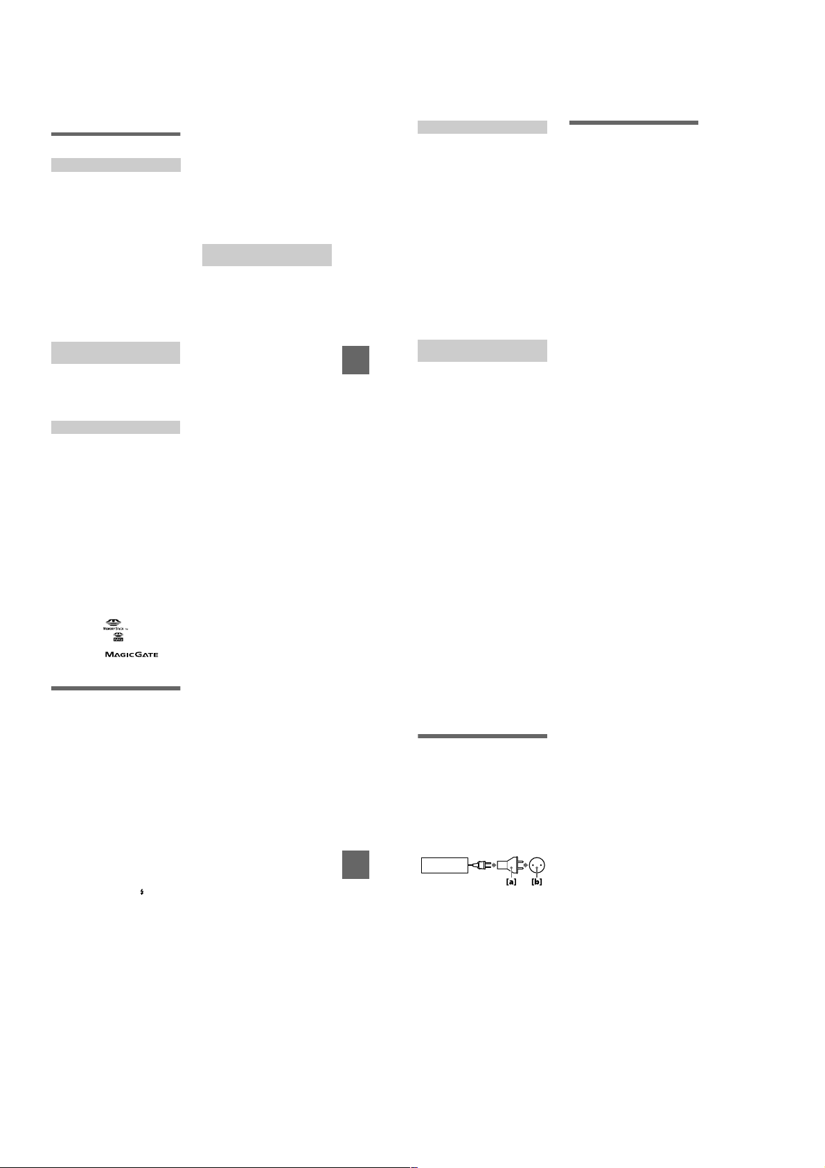
Additional information
Precautions
On cleaning
Cleaning the LCD screen
Wipe the screen surface with a clean i ng
cloth (not supplied) or a LCD cleaning kit
(not supplied) to remove fingerprints, dust,
etc.
Cleaning the camera surface
Clean the camera surface with a soft cloth
slightly moistened with water, then wipe the
surface dry. Do not use any type of solvent
such as thinner, alcohol or benzine as this
may damage the finish or the casing.
After using your camera at the
seashore or other dusty locations
Clean your camera carefully. Otherwise, the
salty air may corrode the metal fittings or
dust may enter the inside of your camera,
causing a malfunction.
Note on operating
temperature
Your camera is designed for use between the
temperatures of 0°C and 40°C (32°F and
104°F). Recording in extremely cold or hot
places that exceed this range is not
recommended.
On moisture condensation
If the camera is brought directly from a cold
to a warm location, or is placed in a very
damp room, moisture may condense inside
or outside the camera. Sho uld t his occur, the
camera will not operate properly.
Moisture condensation occurs
easily when:
•
The camera is brought from a cold location
such as a ski slope into a warmly heated
room.
•
The camera is taken from an airconditioned room or car interior to the hot
outdoors, etc.
How to prevent moisture
condensation
When bringing the camera from a cold place
to a warm place, seal the camera in a plastic
bag and allow it to adapt to conditions at the
new location over a period of time (about an
hour).
If moisture condensation occurs
Turn off the camera and wait about an hour
for the moisture to evaporate. No te that if
you attempt to record with moi s ture
remaining inside the lens, you will be unable
to record clear images.
On AC power adaptor (not
supplied)
•
Unplug the unit from the wall outlet
(mains) when you are not using the unit for
a long time.
•
To disconnect the po wer cord (m ains lead ),
pull it out by the plug. Never pull the
power cord (mains lead) itself.
•
Do not operate the unit with a damaged
cord (mains lead) or if the unit has been
dropped or damaged.
•
Do not bend the power cord (mains lead)
forcibly, or pl ace a hea vy obj ect on it . This
will damage the cord (mai ns le ad) and may
cause fire or electrical shock.
•
Prevent metallic objects from co ming into
contact with the metal parts of the
connecting section. If this happens, a short
may occur and the unit may be damaged.
•
Always keep metal contacts clean.
•
Do not disassemble the unit.
•
Do not apply mechanical shock or drop the
unit.
•
While the unit is in use, particularly during
charging, keep it away from AM receivers
and video equipment. AM reception and
video operation are disturbed.
•
The unit becomes warm during use. This is
not a malfunction.
•
Do not place the unit in locations that are:
—Extremely hot or cold
—Dusty or dirty
—Very humid
—Vibrating
On battery pack (not supplied)
•
Use only the specified charger with the
charging function.
•
To pre ven t accide nt from a short circuit , do
not allow metal objects to come into
contact with the battery termin al s.
•
Keep the battery pack away fro m fire.
•
Never expose the battery pack to
temperatures above 60°C (140°F), such as
in a car parked in the sun or under direct
sunlight.
•
Keep the battery pack dry.
•
Do not expose the battery pack to any
mechanical shock.
•
Do not disassemble nor modify the battery
pack.
•
Install the battery pack to the camera
securely.
•
Charging while some capacity remains
does not affect the original battery
capacity.
If any problem occurs, unplug your camera
and contact your nearest Sony dealer.
On internal rechargeable
button battery
Additional information
This camera has an internal rechargeable
button battery for maintaining the date and
time and other settings regardless of whether
the power is on or off. This rechargeable
button battery is constantly charged as long
as you are using the camera. However, if
you use the camera for only short periods it
discharges gradually, and if you do not use
the camera at all for about one month it
becomes completely discharged. In this
case, be sure to charge this rechargeable
button batte ry before using the camera.
However, even if this rechargeable button
battery is not charged, you can still use the
camera as long as you do not record the date
and time.
Charging method
Connect the camera to a wall outlet (mains)
with the AC power adaptor (not supplied),
or install a charged battery pack or new
alkaline batteries, and leave the camera for
24 hours or more with the POWER button
set to OFF.
On “Memory Sticks”
“Memory Stick” is a new compact, portable
and versatile IC recording medium with a
data capacity that exceeds a floppy disk.
“Memory Stick” is specially designed for
exchanging and sharing digital data among
“Memory Stick” compatible products.
Because it is removable, “Memory Stick”
can also be used for external data storage.
There are two types of “Memory Sticks”:
general “Memory Sticks” and “MagicGate
Memory Sticks” that are equipped with the
MagicGate* copyright protection
technology.
You can use both types of “Memory Stick”
with your camera. However, because your
camera does not support the MagicGate
standards, data recorded with your c amera is
not subject to MagicGate copyright
protection.
MagicGate is copyright protection
∗
technology that uses encryption
technology.
Notes
•
Do not remove the “Memory Stick” while
reading or writing data.
•
Data may be damaged if:
—you remove the “Memory Stick” or turn
off your camera while reading or
writing data.
—you use the “Memory Stick” in a
location subject to the effects of static
electricity or noise.
•
Do not attach any other mater ia l than the
supplied label on th e labeling position .
•
Attach the label so that it does not stick out
from the proper attachment location.
•
When you carry or store the “Memory
Stick,” put it in its supplied case.
•
Do not touch the terminals of a “Memory
Stick” with your hand or a metal object.
•
Do not strike, bend or drop the “Memory
Stick.”
•
Do not disassemble or modify the
“Memory Stick.”
•
Do not allow the “Memory Stick” to get
wet.
“Memory Stick”, , “MagicGate
Memory Stick” and are trademarks of
Sony Corporation.
“MagicGate” and are
trademarks of Sony Corporation.
About “InfoLITHIUM”
battery pack (not
supplied)
What is the “InfoLITHIUM” battery
pack?
The “InfoLITHIUM” battery pack (not
supplied) is a lithium-ion battery pack that
has functions for communicating
information related to operating conditions
between your camera and the AC power
adaptor (not supplied).
The “InfoLITHIUM” battery pack
calculates the power cons umption acco rding
to the operating conditions of your camera,
and displays the remaining battery time in
minutes.
Charging the battery pack
•
Be sure to charge the battery pack before
you start using your camera.
•
We recommend charging the battery pack in
an ambient temperature of between 10°C to
30°C (50°F to 86°F) until the /CHG lamp
goes out, indicating that the battery pack is
fully charged. If you charge the battery
pack outside of this temperature range, you
may not be able to efficiently charge the
battery pack.
•
After charging is completed, disconnect
the AC power adaptor from th e DC IN jack
on your camera or remove the battery
pack.
Effective use of the battery pack
•
Battery performance decreases in lowtemperature surroundings. So, the time that
the battery pack can be used is shorter in
cold places. We recommend the following
to use the battery pack longer:
—Put the battery pack in a p oc k et close to
your body to warm it up, and insert it in
your camera immediately before you
start taking shots.
•
Frequently using the LCD panel or
frequently operating the zoom wears out
the battery pack faster.
•
Be certain to turn the POWER to off when
not taking shots or playing back on your
camera.
•
We recommend having spare batteries
handy for two or three times the expected
shooting time, and make a trial shots
before taking the actual shots.
•
Do not expose the battery pack to water.
The battery pack is not water-resista nt.
Remaining battery time indicator
•
If the power goes off although the battery
remaining indicator indicates that the
battery pack has enough power to operate,
charge the battery pack fully again so that
the indication on the battery remaining
indicator is correct. Note, ho we ver, that the
correct battery indication so me times will
not be restored if it is used in high
temperatures for a long time or left in a
fully charged state, or the battery pack is
frequently used. Regard the remaining
battery time indication as the approximate
shooting time.
•
The E mark indicating there is little
remaining battery time sometime s f la she s
depending on the operating conditions or
ambient temperature and en vironment e ven
if the remaining battery time is 5 to
20 minutes.
How to store the battery pack
•
Even if the battery pack is not used for a
long time, store it in a dry, cool place after
fully charging it once per year and then
using the battery pack up on your camera.
This is to maintain the batter y pa ck’s
functions.
•
To use the battery pack up on your camera,
leave the POWER to on in slide sh o w
playback mode until the power goes off.
71
72
Battery life
•
The battery life is limited. Battery capacity
decreases little by little as you use it mor e
and more, and as time passes. When the
battery operating time is shortened
considerably, a probable cause is that the
battery pack has reached the end of its life.
Please buy a new battery pack.
•
The battery life varies according to how it
is stored and operating conditions and
environment for each battery pack.
Using your camera
abroad
Power sources
You can use your camera in any
country or area with the battery charge r
(not supplied) within 100 V to 240 V
AC, 50/60 Hz. Use a commercially
available AC plug adaptor
necessary, depending on the design of
the wall outlet (mains)
AC-LS1A
Additional information
Watching the playback picture on
TV
If you want to view the playback
picture on a TV, you need a TV having
a video input jack and a video
connecting cable.
The color system of the TV must be
the same as that of your digital still
camera. Check the following list:
NTSC system
Bahama Islands, Bolivia, Canada,
Central America, Chile, Columbia,
Ecuador, Jamaica, Japan, Korea,
Mexico, Peru, Surinam, Taiwan, the
Philippines, the U.S.A., Venezuela, etc.
[a]
, if
[b]
.
PAL system
Australia, Austria, Belgium, China,
Denmark, Finland, Germany, Great
Britain, Holland, Hong Kong, Italy,
Kuwait, Malaysia, New Zealand,
Norway, Portugal, Singapore, Spain,
Sweden, Switzerl and, Thailand, etc.
PAL-M system
Brazil
PAL-N system
Argentina, Paraguay, Uruguay
SECAM system
Bulgaria, Czech Republic, France,
Guiana, Hungary, Iran, Iraq, Monaco,
Poland, Russia, Slovak Republic,
Ukraine, etc.
73
74
1-18
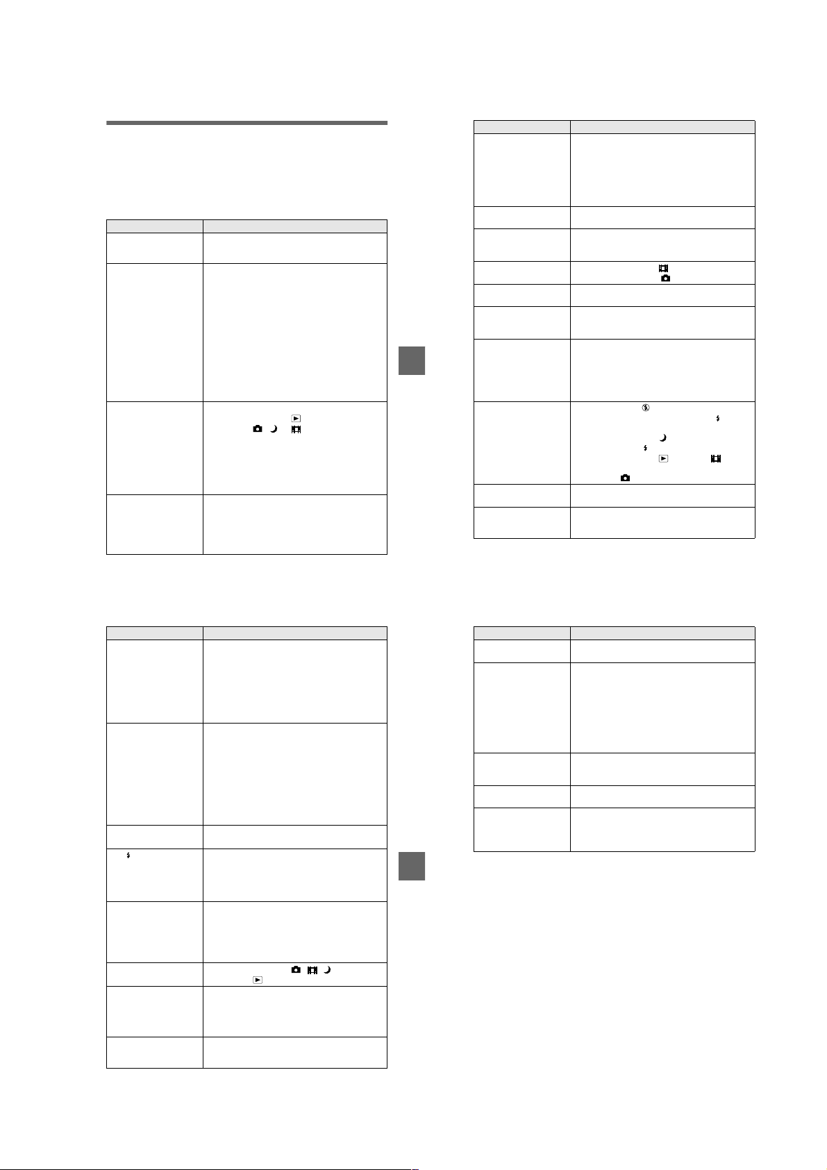
Troubleshooting
If you experience trouble with your camera, first check the following items. Should
your camera still not operate properly after you have made these checks, press the
reset button located on the bottom. (If you press the reset button, the date and time
setting is cleared.) Shou l d your camera still not operate properly, consult your Sony
dealer or local authorized Sony service facility. If code displays (C:
appear on the LCD screen, the self-diagnosis display function is working
(page 83).
Symptom Cause and/or Solution
The power is not turned on
if you press the POWER
button.
Your camera does not
work.
Your camera cannot
record images.
The LCD screen does not
light when the power is
turned on.
Press and hold down the POWER butto n for
t
approximately one second.
•
The battery level is low (the E indicator appears
on the LCD screen).
Replace the alkaline bat t er ie s or charge the
t
battery pack (pages 10, 12).
•
The AC pow er adaptor is not connected securely.
Connect it firmly to the DC IN jack of your
t
camera and a wall outlet (mains) (pages 12, 14).
•
The built-in microcomputer is not working
properly.
Disconnect and then reconnect all power
t
sources after one minute. Then turn the power
on and check that the cam era works properly.
Press the reset button located on the bottom
using a sharp-pointed ob je ct.
•
You cannot record images while charging the flash.
•
The mode dial is set to or SET UP.
Set it to , or (pages 19, 26).
t
•
No “Memory Stick” has been inserted into your
camera.
Insert a “Memory Stick” (page17).
t
•
The write-protect tab on the “Memory St ick” is set
to LOCK.
Set it to the recording position.
t
•
The power was turned off with the LCD screen se t
to OFF the last time the camera was used.
The camera retains the settings from the last
t
time it was used. If you turn the power off with
the LCD screen set to OFF, the LCD is still set
to OFF the next time you turn the power on .
ss
ss:ss
ss
ssss
ssss
)
Symptom Cause and/or Solution
The picture is out of focus. •Your camera is not in macro rec o r di ng mode when
The resizing functi on doe s
not work.
Images recorded in TEXT
mode are blurry.
You cannot record images
in TEXT mode.
You cannot display a print
mark.
The picture is noisy.
The picture is too dark.•You are shooting a subject with a light source
Additional information
The flash does not work. •The flash is set to .
The date and time are
recorded incorrectly.
Vertical streaks appear
when you are shooting a
very bright subject.
you shoot a subject that is abou t 3 to 25 cm (1 3 /1 6
to 9 27/32 inches) from the lens.
Set the macro recording mode (page 53).
t
Press the zoom button to set to the W side.
t
•
The focus preset is select ed.
Cancel the function (page 52).
t
•
Y ou can not resi ze mo ving i mages, t ext images, Clip
Motion and uncompressed images.
•
Light is not striking the subj ect evenly.
Adjust so that the lighting strikes the subject
t
evenly.
•
The mode dial is set to .
Set the mode dial to .
t
•
You cannot display prin t ma rks on moving images,
text images and Clip Motion images.
•
Your camera is placed near a TV or other
equipment that uses stro ng m agnets.
Move your camera away from the TV, etc.
t
behind the subject.
Adjust the exposure (p age 53).
t
•
The brightness of the LCD scree n is to o low.
Adjust the brightness of the LCD screen
t
(page 70).
Set the flash to auto (no indicator) or
t
(page 24).
•
The mode dial is set to .
Set the flash to .
t
•
The mode dial is set to , SETUP or (MPEG
MOVIE).
Set it to .
t
•
The date and time are not set correctly.
Set the correct date an d t ime (page 15).
t
•
The smear phenomenon is happening.
This is not a malfunction.
t
Symptom Cause and/or Solution
The battery life is short.•You are recording/playing back images under
The battery remaining
indicator is incorrect.
Or sufficient battery
remaining indicator is
displayed but the power
runs out soon. (when
using the “InfoLITHIUM”
battery pack)
You cannot charge the
battery pack.
The /CHG lamp flashes
during charging the
battery pack.
Digital zoom does not
function.
Your camera cannot play
back images.
The image and sound are
interfered by noise when
you play back an image on
a personal computer.
The image cannot be
played back on a personal
computer.
extremely cold temperatures.
•
The battery pack is not charged enou gh.
Charge the battery pack fully.
t
•
Alkaline batteries or the battery pack is dead.
Replace the battery (p age 10).
t
•
You are not using the recommended batteries.
Use the recommended batteries (pages 10, 88).
t
•
You have used the camera for a long time in an
extremely hot or an extremely cold location.
•
The battery pack is dead.
Replace the battery pack with a new one
t
(page 10).
•
The battery pack is discharged.
Install a charged battery pack (pages 10, 12).
t
•
A deviation has occurred in the remaining battery
time.
Fully charge the battery pack (page 12).
t
•
The camera is turned on.
Turn the camera off (page 12).
t
•
The battery pack is not installed correctly.
Install the battery pack correctly (page10).
t
•
The battery pack has malfunctioned.
Contact your Sony dealer or local authorized
t
Sony service facility.
•
The digital zoom cannot be used when recording a
moving image with [MOVING IMAGE] set to
[MPEG MOVIE], or the LCD screen is OFF.
•
[DIGITAL ZOOM] is set to [OFF].
Set [DIGIT AL ZOOM] to [ON] in the menu
t
settings.
•
The mode dial is set to , , or SET UP.
Set it to (pages 28, 29).
t
•
You are playing back the file direc t ly fr om the
“Memory Stick.”
Copy the file to the hard disk of the personal
t
computer and then play back the file from the
hard disk (page 35).
Consult the personal computer or software
t
manufacturer.
75
76
Symptom Cause and/or Solution
Y our camera cannot delete
an image.
The power turns off
suddenly.
The image does not
appear on the TV screen.
A file error occurs when
you play back a file.
The picture is
monochrome (black and
white).
Additional information
•
The image is protected.
Cancel the protection (page63).
t
•
If you do not operate the ca m er a for about three
minutes while the power is o n, the camera turns off
automatically to prevent wearing down the battery
(page 11).
The auto-power off functi on (page 11) is
t
activated. Turn on the camera.
•
The battery is discharged.
Replace it with a charged battery or new
t
alkaline batteries.
•
The video output signal se tti ng of your camera is
incorrect.
Change the setting (page 70).
t
•
The image size is larger than 160 0×1200 (DSCP50) or 1280×960 (D SC-P30).
•
The camera is set to TEXT mode.
Cancel TEXT mode (page 49).
t
•
P. EFFECT is set to B&W mode.
Cancel B&W mode (page 55).
t
77
78
1-19

Symptom Cause and/or Solution
Your personal computer
does not recognize your
camera.
No function works though
the power is on.
•
The battery level is low.
Use the AC power adaptor (not su pplied)
t
(page 14).
•
The camera is turned off.
Turn on the camera.
t
•
The USB cable is not connected firmly.
Disconnect the USB cable , a nd connect it again
t
firmly. Make sure that “USB MODE” is
displayed on the LCD screen (pages 32, 34).
•
The USB connectors on your personal computer are
connected to other equipment besides the keyboard,
the mouse, and your camera.
Disconnect the USB cab le s exce pt for the ones
t
connected to the keyboard, the mouse, and your
camera.
•
The USB driver is not installed.
Install the USB driver (page32).
t
•
[USB CONNECT] is set to [PTP] in the setup
settings.
Set it to [NORMAL] (page 70).
t
•
Since the camera is connec te d t o a computer with
the USB cable before installing the USB driver, the
drive is not recognized by the computer.
Delete the drive which is not recognized, then
t
install the USB driver. For details, se e the
procedure on page 80.
Remove the battery pack, then install it again
t
after about one minute. If the function still do
not work, press the reset button located on the
bottom using a sharp-po i nt ed object. (If you
press the reset button, the date and time setting
is cleared.)
Reinstall the USB driver when using Windows 98, Windows
98SE, Windows Me and Windows 2000 Professional
Perform all steps without skipping.
T urn on your computer and allow Windows to load.
1
Connect the USB jack on the camera and the computer with the
2
supplied USB cable.
Insert a “Memory Stick”.
3
Connect the AC power adaptor to your camera and then to a wall
4
outlet (mains), and turn on the power of your camera.
Open “Device Manager” on Windows.
5
For Windows 98, Windows 98SE and Windows Me users:
Open [Control Panel] from [ My Computer], then double-click
1
[System].
“System propertie s ” is displayed. Click the [Device Manager] tab located at
2
the top.
Click [ Sony DSC] in [ Other devices], then click the [Delete (E)]
3
button located at the lower-right corner.
For Windows 2000 Professional users:
Log in with the permission of administrator.
*
Open [Control Panel] from [ My Computer], then double-click
1
Additional information
[System].
“System properties” is displayed. Click the [Hardware] tab located at the top,
2
then click the [Device Manager (D)] button.
Click [View] in [Device Manager], then click [Devices by type (E)].
3
Right-click [ Sony DSC] in [ Other devices], then click [D el ete (E)].
4
After the message appears to verify that you delete the device, click
6
“OK.”
Turn off the camera, disconnect the USB cable, and restart the
7
computer.
Install the USB driver in the supplied CD-ROM to the computer
8
following the procedure on page 32.
Warning and notice messages
Various messages appear on the LCD screen. Check the corr esponding descriptions
in the following list.
Message Meaning
NO MEMORY STICK No “Memory Stick” has been inserted.
SYSTEM ERROR Turn the power off and on again.
MEMORY STICK ERROR
FORMAT ERROR Failed to format the “Memory Stick.”
MEMORY STICK LOCKED The write-protect tab on the “Memory
NO MEMORY SPACE The capacity of the “Memory Stick” is
NO FILE No image has been recorded on the
FILE ERROR An error occurred while playing back the
FILE PROTECT The image is protected against er asure.
DIRECTORY ERROR A directory with the same name already
IMAGE SIZE OVER You are playing back an image of a size
INVALID OPERATION You are playing back a file that was
E
CANNOT DIVIDE • The file is not long enough to be
•
The inserted “Memory Stick” cannot
be used with your camera, or i s
damaged.
•
The “Memory Stick” is not inserted
correctly.
Stick” is set to the LOCK position.
full, and you cannot record im ages.
“Memory Stick.”
image.
exists.
that cannot be played back wi t h your
camera.
created on equipment other than your
camera.
The battery level is low or zero.
Depending on the conditio ns of use or
the type of battery pack, the indicator
may flash even though there is still 5 to
20 minutes of remaining battery time
left.
divided.
• The file is not a moving i m age.
79
80
Message Meaning
Additional information
The amount of light is not su fficient or
the shutter speed is too slow. (Mount the
camera on a tripod or ot herwise secure
the camera in place.)
81
82
1-20

Self-diagnosis display
Your camera has a self-diagnosis display. This
function displays the camera condition on the
LCD screen with a comb i nation of a letter and
four digits of numbers. If this occurs, check the
following code chart. The code informs you of the
camera’s curr ent condition. The last two digits
(indicated by ss) will differ de pending on the
state of the camera.
Self-diagnosis display
•
C:ss:
You can reverse the camera
malfunction yourself.
•
E:ss:
Contact your Sony dealer or local
authorized Sony service facility.
First three digits Cause and/or Corrective Action
•
C:32:
ss
C:13:
ss
E:92:
ss
E:61:
ss
E:91:
ss
If you are unable to solve the problem even after trying the corrective
actions a few times and when the camera is not reset even if you press the
reset button located on the bottom, contact your Sony dealer or local
authorized Sony service facility.
There is trouble with your camera’s hardware.
Turn the power off and on again.
t
•
An unformatted “Memory Stick” is insert ed.
Format the “Memory Stick” (page 69).
t
•
The inserted “Memory Sti ck” cannot be used with your
camera, or is damaged.
Insert a new “Memory Stick” (page 17).
t
•
You are using a battery pack that is not “InfoLITHIUM”
compatible.
Use an “InfoLITHIUM” battery pack.
t
•
You installed or removed the “InfoLITHIUM” battery pack
when using the AC adapter.
Turn the power of and on again.
t
•
A camera malfunction that you cannot reverse has occurred.
Contact your Sony dealer or local aut horized Sony
t
service facility and inform them of the 5-digit service
code. (example: E:92:10)
•
A camera malfunction that you cannot reverse has occurred.
Contact your Sony dealer or local aut horized Sony
t
service facility and inform them of the 5-digit service
code. (example: E:61:10)
C:32:ss
ss
ss
83
LCD screen indicators
The indicators during recording still images
qd
890 qsqa
1
min
2
3
SOLARIZE
4
5
6
7
+
WB
EV
qf
qg
qh
qj
qk
ql
w;
ISO
wa
A Battery remaining indicator
B Flash mode/red eye reduction/
white balance/AF illuminator
indicator
C Date/time/ISO number indicator
D Sharpness indicator
Additional information
E Picture effect indicator
F AF frame
G Spot light-metering cross hair
H AE/AF lo ck indicator
I Recording mode indicator
J Image size indicator
K Image quality indicator
L TWILIGHT mode indicator
M Remaining number of
recordable images indicator/
Self-diagnosis function
indicator
N Remaining memory capacity
indicator
O Macro /focus mode 9
indicator
P EV level indicator
Q Aperture value indicator
R Shutter speed indicator
S Self-timer indicator
T Light amount warning indicator
U Menu and guide menu
Pressing MENU switches the
menu on/off.
Additional information
85
The indicators during recording moving images
45 6
1
min
2
3
STANDBY
SOLARIZE
7
+
WB
EV
A Battery remaining indicator
B White balance indicator
C Picture effect indicator
D Recording mode indicator
E Image size indicator
F Recording time (maximum
recordable time) indicator/
Self-diagnosis function
indicator
G Remaining memory capacity
indicator
H Macro /focus mode 9
indicator
I Self-timer indicator
J Spot light-metering cross hair
K Menu and gu id e m e nu
Pressing MENU switches the
menu on/off.
When playing back still images
45 76
120
min
8
9
0
qa
A Protect/print mark indicator
B Zoom scaling indicator
C File name
D Recording mode indicator
E Image size indicator
F Image number
1
2
3
640
x1.3
FILE BACK/NEXTPLAY
8
11/12
9
G Number of stored images in
“Memory Stick”
H Remaining memory capacity
indicator
I Recording date of the playback
image/menu and guide menu
When playing back moving images
4
6/8
0:12
5
Additional information
60
min
12 3
320
6
7
DELETE
PROTECT
OK
A Recording mode indicator
B Image size indicator
C Image number/number of
stored images in “Memory
Stick”
D Remaining memory capacity
indicator
PRINT SLIDE
8
E Counter
F Playback image
G Play bar
H Menu and guide menu
(play/pause/fast-forward/
rewind)
86
87
1-21

Notes on Using
Batteries
Power save mode
When operating the camera with size
AA alkaline batteries, set POWER
SAVE in the SET UP screen to ON.
This increases the battery efficiency
and life when recording still images.
When POWER SAVE is ON
•
When recording with the L CD screen
turned on, the LCD scr een turns off
while the flash is charging (while the
/CHG lamp flashes).
•
The time from when you pr ess the
shutter button until the image is
recorded is slightly longer than when
POWER SAVE is OFF.
•
The focus is only aligned when the
shutter button is depressed halfway,
even when auto focusing is activated.
Power save mode
•
The factory setting is ON (page 70).
•
Power save mode is also effective
when using an “InfoLITHIUM”
battery pack (NP-FS11, not
supplied), but in this case recording
can be performed more com f ortably
by setting POWER SAVE in the SET
UP screen to OFF.
Handling precautions for size
AA batteries
•
The batteries may be hot
immediately after using the camera.
Wait until the batteries have cooled
before removing them.
•
Remove the batteries when yo u w i ll
not be using the camera for a long
time.
•
Do not disassemble batteri es, short
the terminals with metallic obje cts, or
place batteries in or near he at
sources.
•
Be sure to replace both batteries at
the same time. In addition, do not
mix new and old batt eries or diff erent
types of batteries such as alkaline and
nickel metal hydride batterie s.
Batteries that can be used
•
“InfoLITHIUM” battery pack
(NP-FS11) (recommended, not
supplied)
•
Size AA alkaline batteries (2)
•
Size AA nickel metal hydride
batteries (2)
•
Size AA nickel-cadmium batteries
(2)
Notes
•
When using size AA alkaline batteries, we
recommend Sony Stamina alkaline
batteries. Other batteries may not bring out
the full performance of the camera.
•
When using the camera in low temperat ure
environments, use the “InfoLITHIUM”
battery pack (NP-FS11, not supplied). The
performance of alkaline batteries drop s
significantly at low temperatures, making
use impossible.
•
Nickel metal hydride batteries and nickelcadmium batteries can be use d, but the
battery remaining time may not be
displayed correctly.
•
Manganese and primary lithium batteries
cannot be used with the camera.
88
1-22 E
1-22

• This set can be disassembled in the order shown below.
DSC-P30/P50
2-1. CABINET (R) ASSEMBLY
(Page 2-1)
2-2. CABINET (FRONT) BLOCK
ASSEMBLY (Page 2-1)
DSC-P30/P50
SECTION 2
DISASSEMBLY
2-3. DD-158 BOARD
(Page 2-2)
SERVICE POSITION
(DD-158 BOARD)
(Page 2-2)
2-6. OPTICAL FINDER
(Page 2-3)
2-4. CHASSIS (MAIN)
ASSEMBLY (Page 2-3)
2-5. LENS BLOCK ASSEMBLY
(Page 2-3)
2-7. ZOOM LENS
(Page 2-3)
Note: Follow the disassembly procedure in the numerical order given.
2-1. CABINET (R) ASSEMBLY
1 Screw
(M2)
2-8. JK-206 BOARD
(Page 2-4)
2-9. DC JACK
(Page 2-4)
2-10. SY-66 BOARD
(Page 2-4)
2-11. LCD MODULE
(Page 2-4)
SERVICE POSITION
(SY-66 BOARD)
(Page 2-5)
2-2. CABINET (FRONT) BLOCK ASSEMBLY
6 Two flexible boards
(CN501, 708)
3 Screw
(M2)
2 Two screws
(M2)
3 Cabinet (R)
assembly
4 Two screws
2-1
(M2)
1 Open the MS lid.
2 Screw
(M2)
5 Cabinet (front)
block assembly

2-3. DD-158 BOARD
3 Screw
(DIA. 1.7 × 4)
1 Two flexible boards
(CN003, 004)
2 Two connectors
(CN001, 002)
4 Screw
(DIA. 1.7 × 4)
5 DD-158 board
[SERVICE POSITION (DD-158 BOARD)]
Note 1: Don’t use the 12 pin flexible board of CPC-9 jig.
Note 2: The old CPC-9 jig (Parts code: J-6082-393-B)
It causes damage to the unit.
cannot be used, because it cannot operate
the adjustment remote commander.
Adjusting remote
commander
CPC-9 jig
(J-6082-393-C)
18
1
Regulated power supply
(6.0 to 7.2 Vdc)
DD-158 board
18
1
AC power
adaptor
Color monitor
AC IN
2-2
 Loading...