

Page 1

DSC-P150
Ver 1.1 2005.04
Revision History
Revision History
Link
Link
Before starting adjustments
Before starting adjustments
Adjusting items when replacing main parts and boards
Adjusting items when replacing main parts and boards
CAMERA SECTION ADJUSTMENTS
CAMERA SECTION ADJUSTMENTS
PREPARATIONS BEFORE ADJUSTMENTS
PREPARATIONS BEFORE ADJUSTMENTS
ADJUSTMENT PROGRAMS
ADJUSTMENT PROGRAMS
VIDEO SYSTEM ADJUSTMENTS
VIDEO SYSTEM ADJUSTMENTS
CAMERA SYSTEM ADJUSTMENTS
CAMERA SYSTEM ADJUSTMENTS
LCD SYSTEM ADJUSTMENTS
LCD SYSTEM ADJUSTMENTS
ERROR
ERROR
SECTION 6
ADJUSTMENTS
SERVICE MODE
SERVICE MODE
SERVICE MODE
SERVICE MODE
Auto-ADJ
INITIALIZATION OF DATA
INITIALIZATION OF DATA
•
Use this Service Manual together with the Automatic Adjustment Program (DSC-P150 Auto-Adj Ver1.[]r
Adjustment Program (P150ColorShade.exe).
Note:[] (numeric value) of the file name varies depending on the version of Automatic Adjustment Program.
Contents of LEVEL 2 and LEVEL 3 Service Manual
CONTENTS
1. SERVICE NOTE
2. DISASSEMBLY
3. BLOCK DIAGRAMS
4. PRINTED WIRING BOARDS AND
SCHEMATIC DIAGRAMS
5. REPAIR PARTS LIST
OVERALL
POWER
CD-517 FLEXIBLE,
ST-105 FLEXIBLE,
ST-102, MS-207 FLEXIBLE,
JK-266 FLEXIBLE
EXPLODED VIEWS
ELECTRICAL PARTS
LEVEL 2
a
a
LEVEL 3
✕
✕
✕
CH-146, SY-119 BOARD
✕
a
(CH-146, SY-119 BOARD)
[][]
.exe) and the Color Shading
DSC-P150
9-876-755-51
Sony EMCS Co.
2005D0500-1
© 2005.4
Published by DI Technical Support Section
Page 2

TABLE OF CONTENTS
Section Title Page
6. ADJUSTMENTS
Before Starting Adjustment ·······················································6-1
1-1. Adjusting Items When Replacing
Main Parts and Boards ····················································6-2
6-1. Camera Section Adjustments··········································· 6-3
1-1. Preparations Before Adjustments ····································6-3
1-1-1.List of Service Tools························································6-3
1-1-2.Preparations ·····································································6-4
1-1-3.Precautions ······································································6-5
1. Setting the Switch····························································6-5
2. Subjects ···········································································6-5
3. Preparing the Flash Adjustment Box·······························6-6
1-1-4.Using Method of SEUS ···················································6-7
1. Connection·······································································6-7
2. Operation ·········································································6-7
1-1-5.Precaution on Use of SEUS·············································6-7
1-2. Adjustment Programs ······················································6-8
1-2-1.Automatic Adjustment Program ······································ 6-8
1. Precautions When Using Automatic Adjustment
Program ···········································································6-8
2. Start of Automatic Adjustment Program ·························6-8
3. Function of Each Button on Main Menu Screen ·············6-8
1-2-2.Color Shading Adjustment Program································6-9
1. Application Environment ················································6-9
2. Installation Method··························································6-9
3. Notes When Using the Color Shading Adjustment
Program ···········································································6-9
4. Starting Method of Color Shading Adjustment
Program ···········································································6-9
5. Screen and Function of Each Button of
Color Shading Adjustment Program································6-9
1-3. Video System Adjustments············································6-10
1-3-1.Function of Each Button on Video System
Adjustment Screen ························································6-10
1-3-2.Adjustment Items of Video System Adjustment············ 6-10
1-3-3.Adjusting Method·························································· 6-11
1-4. Camera System Adjustments·········································6-12
1-4-1.Function of Each Button on Camera System
Adjustment Screen ························································6-12
1-4-2.Adjustment Items of Camera System Adjustment ········6-13
1-4-3.Adjusting Method·························································· 6-14
1. Camera Adjustment 1 ····················································6-14
2. Camera Adjustment 2 ····················································6-15
3. Picture Frame Setting (Standard Picture Frame)···········6-16
4. Color Shading Adjustment ············································ 6-17
5. Camera Adjustment 3 ····················································6-18
6. AWB 3200K-5800K Standard Data Input ·····················6-19
7. Color Reproduction Adjustment····································6-20
8. Color Reproduction Check ············································6-21
9. Camera Adjustment 4 ····················································6-22
10. Camera Adjustment 5 ····················································6-23
1-5. LCD System Adjustments ·············································6-24
1-5-1.Function of Each Button on LCD System
Adjustment Screen ························································6-24
1-5-2.Adjustment Items of LCD System Adjustment·············6-24
1-5-3.Adjusting Method·························································· 6-25
1-6. Error···············································································6-26
1-6-1.Error Message································································6-26
1. Connect Error ································································6-26
2. Reset the Camera and Try Again ···································6-26
3. Adjustment Time Out ····················································6-26
4. Adjustment NG······························································6-26
5. Data Save Error ·····························································6-27
Section Title Page
1-6-2.Precautions When an Error Occurred····························6-27
1-7. Initialization of Data······················································6-28
1. Initializing All Page Data ··············································6-28
2. Initializing Single Page Data ·········································6-28
6-2. Service Mode·································································6-29
1. Setting the Test Mode ····················································6-29
2. Bit V alue Discrimination ···············································6-29
3. LED Check ····································································6-30
4. Switch Check (1) ···························································6-30
5. Switch Check (2) ···························································6-31
6. Mode Dial Check···························································6-31
7. Self Diagnosis Code ······················································ 6-31
* The AF illumination frame is shown on page 6-32.
DSC-P150
— 2 —
Page 3

Before starting adjustment
EVR Data Re-writing Procedure When Replacing Board
The data that is stored in the repair board, is not necessarily correct.
Perform either procedure 1 or procedure 2 when replacing board.
Procedure 1
Save the EVR data of the machine in which a board is going to be replaced. Download the saved data after a
board is replaced.
SECTION 6
ADJUSTMENTS
(Machine before starting repair)
Save the EVR data
to a personal computer.
Procedure 2
When the data cannot be saved due to defective f lash memory, or when the flash memory cannot be removed or
installed, save the data from the same model of the same destination, and download it.
(Machine to be repaired)
PC
Save the data.
PC
Download the saved
data to a machine.
Download the data.
(Machine after a board is replaced)
(Machine to be repaired)PC
(The same model of the same destination)
After the EVR data is saved and downloaded, check the
respective items of the EVR data.
(Refer to page 6-2 for the items to be checked.)
DSC-P150
6-1
Page 4

1-1. Adjusting items when replacing main parts and boards
When replacing main parts and boards, adjust the items indicated by z in the following table.
Note 1: The automatic Adjustment Program does not support the “Initialization of data”. Perform it manually.
Note 2: Use the Color Shading Adjustment Program (P150ColorShade.exe).
Replaced parts
Block Mounted parts Board
replacement replacement replacement
Adjusting item Adjustment
(Note 1) Initialization of data
VIDEO adjustment Video output level adj.
CAMERA adjustment 1 Flange back adj.
CAMERA adjustment 2 Flange back check
(Note 2) Color shading adj.
F No. compensation
CAMERA adjustment 3
(Note 2)
CAMERA adjustment 4
CAMERA adjustment 5
LCD adjustment
Mechanical shutter adj.
Light value adj.
AWB 3200K-5800K standard data input
Color reproduction adj.
Color reproduction check
CCD linearity check
CCD white defect compensation check
CCD black defect compensation check
Strobe adj.
Auto focus illumination check
VCO adj.
Contrast adj.
V-COM adj.
White Balance adj.
LCD unit
Back light unit
(CCD imager)
(AF illumination LED)
(Timing gen., CCD signal process)
(Camera DSP)
(Video amp.)
(LCD driver)
LCD901
D901
IC101
D104
IC101
IC301
IC302
IC801
(COMPLETE)
(COMPLETE)
(COMPLETE)
Lens block
Flash unit
LCD block
LCD block
CD-517 board
CD-517 board
CH-146 board
SY-119 board
SY-119 board
SY-119 board
CD-517 board
CH-146 board
SY-119 board
z
zz z
zz zz
zz zz
zzzzzz
z
z
z
zzz
zzzzzz
zzzzzz
zzzzzz
z
zz
z
zz zz
z
z
zz
z
z
z
zz
zz
DSC-P150
Table 6-1-1
6-2
Page 5
Ver 1.1 2005.04
6-1. CAMERA SECTION ADJUSTMENTS
1-1. PREPARATIONS BEFORE ADJUSTMENTS
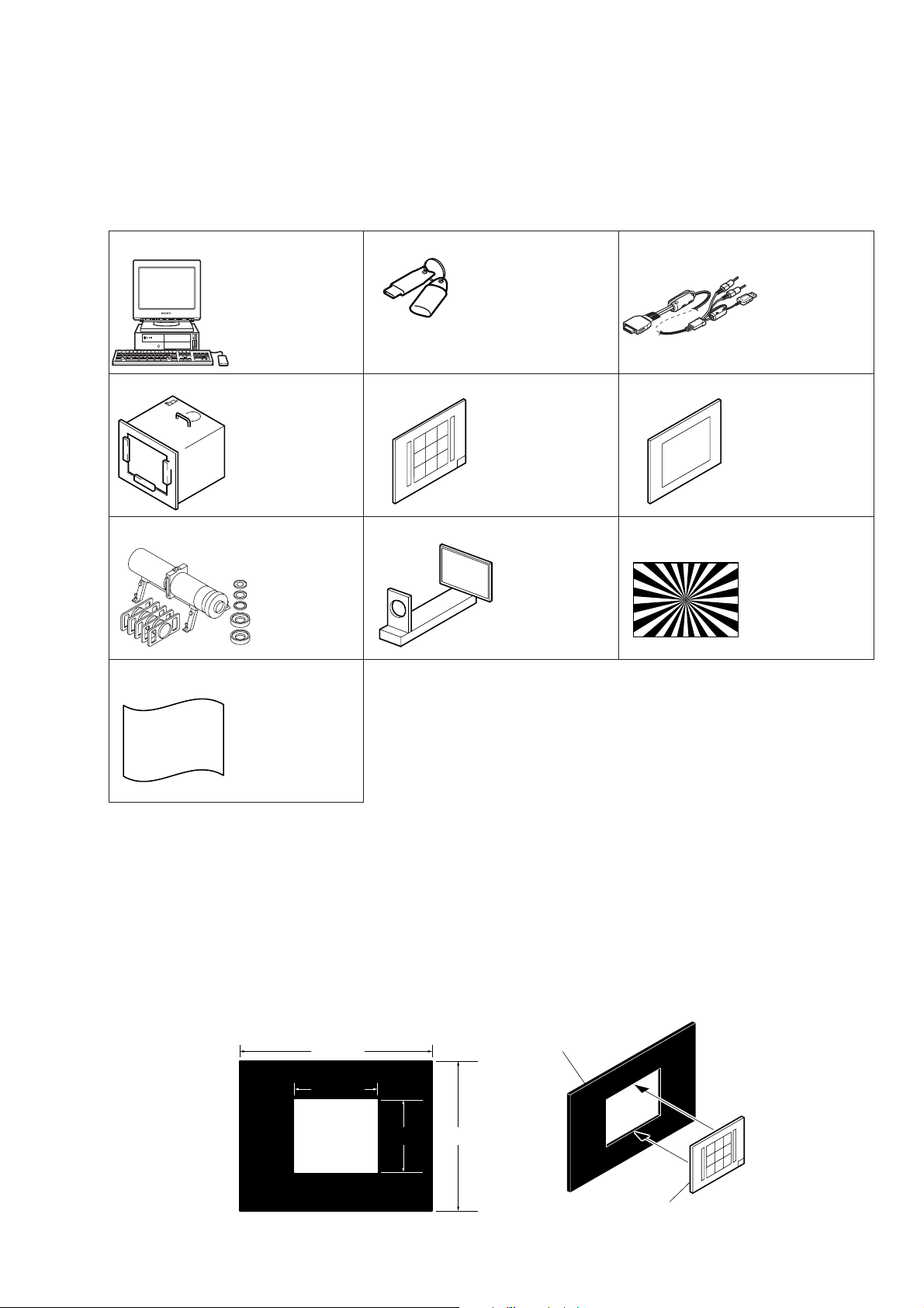
1-1-1. List of Service Tools
• Oscilloscope • Color monitor • AC power adapter
J-1
J-4
J-7
J-10
Personal computer
(Note 1)
Pattern box PTB-450
J-6082-200-A
or
Small pattern box
PTB-1450
J-6082-557-A
Minipattern box
J-6082-353-B
J-2
HASP key and application
for adjustment (SEUS)
Contact our service headquater of each area
how to get the application for adjustment
(SEUS) and HASP key.
J-5
9 colors chart (Note 2)
For PTB-1450:
J-6082-562-A
J-8
Flange back
adjustment jig
J-6082-563-A
J-3
USB, A/V cable for
multi-use terminal
1-829-866-11
J-6
Clear chart
For PTB-450:
J-6080-621-A
For PTB-1450:
J-6082-560-A
J-9
Siemens star chart
J-6080-875-A
Back ground paper
J-2501-130-A
Fig. 6-1-1
Note1: Personal computer
OS: Windows98/98SE/Me/2000/XP Home/XP Pro
RAM: 256MB or more recommended
USB: 2.0 recommended (also compatible with 1.1)
Two connectors are required.
Note2: In using the 9 colors chart on the pattern box PTB-450, adjust the chart size through the procedure shown below so that it
matches to the pattern box PTB-450.
1) Prepare a woody board A of the thickness 5 mm, and paint it mat-black.
2) Fit the 9 colors chart in the woody board A, and secure the chart with a black tape, etc. to shield the light.
woody boad A
360 mm
155 mm
135 mm
280 mm
woody boad A
DSC-P150
9 colors chart
Fig. 6-1-2
6-3
Page 6
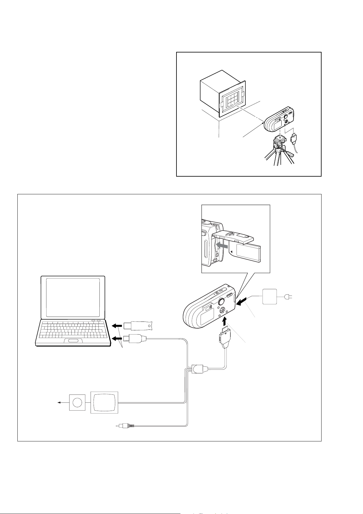
1-1-2. Preparations
1) Connect the equipment for adjustments according to Fig. 6-1-4.
2) Start up the application for adjustment (SEUS).
Pattern box
L
Front of the lens
L=About 11 cm
Fig. 6-1-3
Insert the Memory Stick.
PC
OS: Windows 98/98SE/Me/2000/XP
RAM: 256MB or more recommended
USB: 2.0 recommended (also compatible with 1.1)
Two connectors are required.
HASP Key
To USB
connector
Vectorscope
Terminated
75 Ω
Color monitor
AC power adaptor
AC IN
To DC IN jack
To Multi connector
USB, A/V cable
for multi-use terminal
(1-829-866-11)
Video (yellow)
Audio (Black)
DSC-P150
Fig. 6-1-4
6-4
Page 7

1-1-3. Precautions
1. Setting the Switch
Unless otherwise specified, set the switches as follows and perform adjustments.
1. Mode Dial .......................................... P (Program auto)
2. ZOOM switch (Control switch
block (SW) S002, S003).................... WIDE end
3. Video Out (SET UP setting).............. NTSC
4. Digital Zoom (SET UP setting)......... Off
5. EV (Menu items) ............................... 0EV
6. Focus (Menu items) ........................... Multi AF
7. WB (Menu items) .............................. Auto
8. ISO (Menu items) .............................. Auto
9. Flash Level (Menu items).................. Normal
10. P.Effect (Menu items)........................ Off
11. Saturation (Menu items).................... Normal
12. Contrast (Menu items)....................... Normal
13. Sharpness (Menu items) .................... Normal
9 colors chart (Standard picture frame)
A
Green
Cyan
C14
Effective picture frame
LCD screen or under scan
Fig. a
monitor TV picture
B
Yellow
White
Blue
W14
Red
Magenta
A
A
2
2. Subjects
1) 9 colors chart (Standard picture frame).
When performing adjustments using the 9 colors chart, adjust
the picture frame as shown in Fig. 6-1-5. (Standard picture
frame)
2) Clear chart (Standard picture frame)
Remove the 9 colors chart from the pattern box and insert a
clear chart in its place. (Do not perform zoom operations during this time)
C
B
C
A = B
C =
C14 : Filter for AWB 5800K adjustment
Transparent window
Fig. 6-1-5
B
3
Adjust the camera position and direction
to obtain the LCD screen or the monitor
TV display shown in Fig. a.
DSC-P150
6-5
Page 8

3. Preparing the Flash Adjustment Box
A dark room is required to provide an accurate flash adjustment.
If it is not available, prepare the flash adjustment box as given
below;
1) Provide woody board A, B and C of 15 mm thickness.
woody board A (2)
400 mm
513 mm 513 mm 700 mm
woody board B (2)
Fig. 6-1-6
2) Apply black mat paint to one side of woody board A and B.
3) Attach background paper (J-2501-130-A) to woody board C.
4) Assemble so that the black sides and the background paper
side of woody board A, B and C are internal. (Fig. 6-1-7)
370 mm
700 mm730 mm
woody board A
woody board C (1)
700 mm
woody board B
woody board A
DSC-P150
woody board B
woody board C
Fig. 6-1-7
6-6
Page 9

1-1-4. Using Method of SEUS
The application for adjustment (SEUS) is used to change the coefficient for calculating the signal processing or EVR data. The SEUS
performs two-way communication between PC and set through
the USB terminal. The two-way communication result data can be
written to the nonvolatile memory.
1. Connection
1) Connect the HASP key to the USB terminal of the PC.
2) Connect the PC and set with the USB cable.
3) Confirm that the set starts in the USB mode.
4) Start the SEUS on the PC.
5) Click [Connect] on the SEUS screen. If the connection is normal, the SEUS screen will be as shown in Fig. 6-1-8, indicat-
“connected” state.
ing the
Note: The SEUS will go in
turned off (for instance, by resetting the set). In such a
case, click
“connected” state.
the
[Connect] on the SEUS screen to restore
“disconnect" state, if the set is
2. Operation
• Page change
To change the page, click
the page to be changed. The page is displayed in hexadecimal
notation.
• Address change
To change the address, click [Address] on the SEUS screen and
enter the address to be changed. The address is displayed in
hexadecimal notation.
• Data change
To change the data, click [Set] on the SEUS screen and enter
the data. The data is displayed in hexadecimal notation.
This operation does not write the data to the nonvolatile memory .
• Data saving
To write the all changed data to the nonvolatile memory, click
[Page] on the SEUS screen and enter
[Save] on the SEUS screen and wait for more than 3 sec.
• Data reading
The data displayed on the SEUS screen are the data values at
the time when the pages and addresses were set, and they are
not updated automatically. To check the data change, click
[Read] on the SEUS screen and update the displayed data.
1-1-5. Precaution on Use of SEUS
Wrong SEUS operation could clear correct adjustment data. To
prevent the data clear by mistake, it is recommended to save all
adjustment data by clicking [Page Edit] on the SEUS screen before starting the adjustment.
Fig. 6-1-8
Saving Method:
1) Click [Page Edit] on the SEUS screen to display the SEUS
PAGE EDIT screen.
2) Click [Page], and enter the page number to be saved.
3) Click [Page] to read the data to be saved from the camera.
4) Click [File] and save the data to PC.
Loading Method:
1) Select page: 00, address: 01 and set data: 01.
2) Click [Page Edit] on the SEUS screen to display the SEUS
PAGE EDIT screen.
3) Click [File] and load the data from PC.
4) Click [Write] on the SEUS PAGE EDIT screen.
5) Click [Close] to close the SEUS PAGE EDIT screen.
6) Click [Save] on the SEUS screen.
7) Wait for more than 3 sec.
8) Select page: 80, address: 30, and check that the data is “00”.
9) Select page: 00, address: 01 and set data: 00.
DSC-P150
6-7
Page 10
1-2. ADJUSTMENT PROGRAMS
The DSC-P150 is adjusted with the Automatic Adjustment Program and the Color Shading Adjustment Program.
The Automatic Adjustment Program automatically controls the
adjustment operations that were formerly entered manually on the
operation screen of the SEUS (some adjustments may be manually operated on the SEUS operation screen).
The Color Shading Adjustment Program automatically performs
“Color Shading Adjustment”, “A WB 3200K-5800K Standard Data
Input”, “Color Reproduction Adjustment” and “Color Reproduction Check” of Camera System Adjustment.
1-2-1. Automatic Adjustment Program
1. Precautions When Using Automatic Adjustment
Program
1) The Automatic Adjustment Program writes the adjustment re-
sults such as EVR data to the set through two-way communication with the camera via the SEUS. Accordingly, the Automatic Adjustment Program must be used in the environment
where the SEUS operates.
2) The program run time may vary depending on the environ-
ment of the personal computer used.
3) Even if the Automatic Adjustment Program is used without
starting the SEUS, the SEUS will start automatically when the
adjustment is executed. Howe ver , it may take time for the SEUS
to start, and therefore the Automatic Adjustment Program
should be used with the SEUS started in order to reduce the
program run time.
2. Start of Automatic Adjustment Program
Double-click the application file (DSC-P150 Auto-Adj
Ver_1.[]r
Note:[] (numeric value) of the file name v aries depending on the
[][]
.exe), and the Automatic Adjustment Program will start.
version of Automatic Adjustment Program.
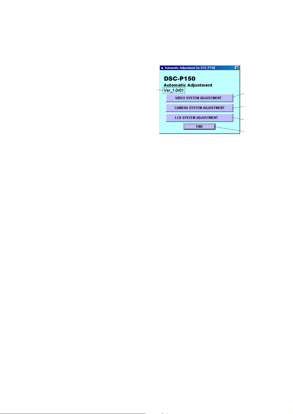
3. Function of Each Button on Main Menu Screen
When the Automatic Adjustment Program started, the Main Menu
screen in Fig. 6-1-9 will appear. On this screen, select each adjustment section.
5
1
2
3
4
Fig. 6-1-9
1 [VIDEO SYSTEM ADJUSTMENT] button
The “VIDEO SYSTEM ADJUSTMENT” screen appears.
2 [CAMERA SYSTEM ADJUSTMENT] button
The “CAMERA SYSTEM ADJUSTMENT” screen appears.
3 [LCD SYSTEM ADJUSTMENT] button
The “LCD SYSTEM ADJUSTMENT” screen appears.
4 [END] button
The Automatic Adjustment Program finishes.
5 This part indicates the version of Automatic Adjustment Pro-
gram.
DSC-P150
6-8
Page 11

1-2-2. Color Shading Adjustment Program
1. Application Environment
OS: Windows 98/98SE/Me/2000/XP
RAM: 256MB or more recommended
USB: 2.0 recommended (also compatible with 1.1)
Two connectors are required.
5. Screen and Function of Each Button of Color
Shading Adjustment Program
1
2. Installation Method
Extract the file compressed in the ZIP format (P150Color
Shade.zip). Execute the extracted file (setup.ex e), and the installer
will start. Install the program following the instructions given on
the installer screen.
3. Notes When Using the Color Shading Adjustment
Program
1) The SEUS must be installed in the PC.
2) The HASP Key for SEUS must be connected to the USB con-
nector. The program will not start unless the HASP Key is
connected.
4. Starting Method of Color Shading Adjustment
Program
Click the [Start] button on the task bar , and click the [DSC- P150
Color Shade Adjustment] from the [Programs], and the program
will start.
2
3
4
5
A
Fig. 6-1-10
1 [Connect] button
Makes connection to the camera and switches the camera to
the adjustment mode. In the case of successful connection to
the camera, the indication at the part A changes to “Connected”
and the following buttons become active.
• [Color Shading Adjustment] button
• [AWB 3200K-5800K Standard Data Input] button
• [Color Reproduction Adjustment] button
• [Color Reproduction Check] button
• [Disconnect] button
2 Adjustment start buttons
Start the adjustment or checking of respective button names.
3 [Disconnect] button
Cancels the connection to the camera.
4 Captured picture display screen
Displays a picture captured by the camera when the adjustment or checking was performed.
5 Vector scope screen
Displays the result of Color Reproduction Check.
DSC-P150
6-9
Page 12

1-3. VIDEO SYSTEM ADJUSTMENTS
1-3-1. Function of Each Button on Video System
Adjustment Screen
Click the
Menu screen, and the “VIDEO SYSTEM ADJUSTMENT” screen
in Fig. 6-1-11 will appear.
1 [To Menu] button
2 [VIDEO Adjustment Start] button
[VIDEO SYSTEM ADJUSTMENT] button on the Main
1
2
43
Fig. 6-1-11
The Main Menu screen comes back.
“Video Adjustment” starts.
1-3-2. Adjustment Items of VIDEO System
Adjustment
The adjustment items of video system adjustment are as listed in
Table 6-1-2. The Automatic Adjustment Program executes the adjustment items if the VIDEO Adjustment Start button is clicked.
Button
Name
VIDEO VIDEO Output
Adjustment Level Adj.
Adjustment Signal Page Address
Arbitrary 8F D0
Table 6-1-2
3 [Reset] button
This button functions same as the Reset button of the camera.
4 [Release Data Setting] button
The data setting at the adjustment is cancelled.
During the data setting, the button color changes from “white”
to “red”. When the data setting is cancelled, the button color
returns to “white”.
(Use this button when an error occurred in the video adjustment. If the adjustment completed successfully, the data setting is automatically cancelled and the button color returns to
“white”.)
DSC-P150
6-10
Page 13

1-3-3. Adjusting Method
[Automatic Adjustment Program execution items and
sequence]
1. Data Setting during Video Adj.
2. Video Output Level Adj.
3. Release of Data Setting during Video Adj.
[Specified value of video output level adj.]
Measurement Point Video terminal of USB, A/V cable
for multi-use terminal
(75 Ω terminated)
Measuring Instrument Oscilloscope
Specified V alue Sync level:
A = 286 ± 5 mV (NTSC mode)
A = 300 ± 5 mV (PAL mode)
Burst level:
B = 286 ± 30 mV (NTSC mode)
B = 300 ± 30 mV (PAL mode)
SEUS operation screen
UP/DOWN key
Fig. 6-1-14
[Adjusting method]
1) Click the [VIDEO Adjustment Start] button.
2) The Automatic Adjustment Program executes the “1. Data Set-
ting during Video Adj.”.
3) If “1. Data Setting during V ideo Adj.” completed successfull y ,
the next message is displayed during the execution of “2. V ideo
Output Level Adj.”. Using the UP/DOWN key on the SEUS
Operation screen, adjust so that the sync level of the video
signals satisfies the specified value. After the adjustment, check
that the burst level of the video signals satisfies the specified
value, and click the [OK] button in the message.
Fig. 6-1-12
4) If the [OK] button button is clicked, “3. Release of Data Set-
ting during Video Adj.” will be executed.
5) Upon successful completion of all items of the VIDEO adjust-
ment, the following message is displayed. Click the [OK] button.
Check on the oscilloscope
B
A
H
Fig. 6-1-15
DSC-P150
Fig. 6-1-13
6-11
Page 14

1-4. CAMERA SYSTEM ADJUSTMENTS
1-4-1. Function of Each Button on Camera System
Adjustment Screen
Click the [CAMERA SYSTEM ADJUSTMENT] button on the Main
Menu screen, and the “CAMERA SYSTEM ADJUSTMENT”
screen in Fig. 6-1-16 will appear.
1
2
4
3
Fig. 6-1-16
1 [To Menu] button
The Main Menu screen comes back.
2 Adjustment start buttons
• [CAMERA Adjustment 1 Start] button
“Camera Adjustment 1” starts.
• [CAMERA Adjustment 2 Start] button
“Camera Adjustment 2” starts.
• [CAMERA Adjustment 3 Start] button
“Camera Adjustment 3” starts.
• [CAMERA Adjustment 4 Start] button
“Camera Adjustment 4” starts.
• [CAMERA Adjustment 5 Start] button
“Camera Adjustment 5” starts.
3 [Reset] button
This button functions same as the Reset button of the camera.
4 [Release Data Setting] button
The data setting at the adjustment is cancelled.
During the data setting, the button color changes from “white”
to “red”. When the data setting is cancelled, the button color
returns to “white”.
(Use this button when an error occurred in the camera adjustment 1-5. If the adjustment completed successfully, the data
setting is automatically cancelled and the button color returns
to “white”.)
DSC-P150
6-12
Page 15

1-4-2. Adjustment Items of Camera System Adjust-
ment
The adjustment items of camera system adjustment are as listed in
Table 6-1-3. The Automatic Adjustment Program divides the adjustment items into four, camera adjustment 1-5. Clicking either
CAMERA Adjustment Start button allows the adjustment item
which corresponds to that button to be executed.
The adjustment conditions of the subject and filter vary depending on which item is adjusted. The Adjustment Program displays
an instruction for the subject and filter as a message during the
adjustment.
Button Name Adjustment Subject
Siemens star chart with ND filter
CAMERA Adjustment 1 Flange Back Adj. for minipattern box (Note 1) or
Flange back adjustment jig
Siemens star
CAMERA Adjustment 2 Flange Back Check (1.0m from front the lens)
(Luminance: 200 to 400 lux)
(Note 2) Color Shading Adj.
F No. Compensation
CAMERA Adjustment 3 Mechanical Shutter Adj.
Light Value Adj. 6F 65 to 67
AWB 3200K-5800K
(Note 2)
CAMERA Adjustment 4 Compensation Check
CAMERA Adjustment 5 Flash adjustment box (50 cm) 6F D8 to EF
Standard Data Input
Color Reproduction Adj. (Standard picture frame) 6E 60 to 67
Color Reproduction Check
CCD Linearity Check
CCD White Defect
CCD Black Defect
Compensation Check
Strobe Adj.
Auto focus illumination Check 6F 10 to 17
Clear chart
(Standard picture frame)
Clear chart
(Standard picture frame)
9 colors chart
Clear chart
(Standard picture frame)
Adjustment Adjustment
Page Address
6D B0 to B7, C0 to C7
6F 18 to 53
6F 60 to 64, 6B to 6D
6F 6B to 6D, B8 to D7
6E 00 to 21, 24 to 49
6E 72 to 75
Note 1: Dark Siemens star chart.
Note 2: Use the Color Shading Adjustment Program
DSC-P150
(P150ColorShade.exe).
Table 6-1-3
6-13
Page 16

1-4-3. Adjusting Method
1. CAMERA Adjustment 1
[Automatic Adjustment Program execution items and
sequence]
1. Data Setting during Camera Adj.
2. Flange Back Adj.
3. Release of Data Setting during Camera Adj.
[Adjusting method]
1) Click the [CAMERA Adjustment 1 Start] button.
2) The Automatic Adjustment Program e xecutes “1. Data Setting
during Camera Adj.”.
3) Upon successful completion of the “1. Data Setting during
Camera Adj.”, the following message is displayed. Set the subject by referring to “Preparation of Flange Back Adj.”.
Preparation of Flange Back Adj.
(Using the minipattern box)
1) The minipattern box is installed as shown in the following figure.
Note 1: The attachment lenses are not used.
Note 2: Take care not to hit the mini-pattern box when ex-
tending the lens.
2) Install the minipattern box so that the distance between it and
the front of lens of camera is less than 3 cm.
3) Make the height of minipattern box and the camera equal.
4) Check the output voltage of the regulated power supply is the
specified voltage ± 0.01 Vdc.
5) Check that the center of Siemens star chart meets the center of
shot image screen with the zoom lens at TELE end and WIDE
end respectively.
Specified voltage:The specified voltage varies according to the
minipattern box, so adjustment the power supply output voltage to the specified voltage written on the sheet which is supplied with the minipattern box.
Below 3 cm
Fig. 6-1-17
4) If the [OK] button is clicked, “2. Flange Back Adj.” and “3.
Release of Data Setting during Camera Adj.” will be executed.
5) Upon successful completion of all items of the CAMERA
Adjustment 1, the following message is displayed. Click the
[OK] button.
Fig. 6-1-18
Minipattern box
Camera
Output voltage : Specified voltage ± 0.01 Vdc
Red (+)
Black (–)
Yellow (SENS +)
White (SENS –)
Black (GND)
Regulated power supply
Output current : more than 3.5 A
Need not connected
Fig. 6-1-19
Preparation of Flange Back Adj.
(Using the flange back adjustment jig)
(Luminance: about 300 lux)
1) Install the flange back adjustment jig so that the distance between it and the front of lens of camera is less than 3 cm.
Note 3: Take care not to hit the mini-pattern box when ex-
tending the lens.
2) Make the height of flange back adjustment jig and the camera
equal.
3) Check that the center of chart meets the center of shot image
screen with the zoom lens at TELE end and WIDE end respectively.
Flange back adjustment jig
Below 3 cm
DSC-P150
Camera
Fig. 6-1-20
6-14
Page 17

2. CAMERA Adjustment 2
[Automatic Adjustment Program execution items and
sequence]
1. Data Setting during Camera Adj.
2. Flange Back Check
3. Release of Data Setting during Camera Adj.
[Adjusting method]
1) Click the [CAMERA Adjustment 2 Start] button.
2) The Automatic Adjustment Program ex ecutes “1. Data Setting
during Camera Adj.”.
3) Upon successful completion of the “1. Data Setting during
Camera Adj. ”, the follo wing message is displayed. Set the subject in accordance with the message.
Fig. 6-1-21
4) Click the [OK] button is clicked, “2. Flange Back Check” is
executed. The following messages are displayed, and then operate the camera to make a check in accordance with the messages.
6) Upon successful completion of all items of the CAMERA
Adjustment 2, the following message is displayed. Click the
[OK] button.
Fig. 6-1-23
5) Upon completion of “2. Flange Back Check”, “3. Release of
DSC-P150
Fig. 6-1-22
Data Setting during Camera Adj.” is executed.
6-15
Page 18

3. Picture Frame Setting (Standard Picture Frame)
In the “Color Shading Adjustment”, “CAMERA Adjustment 3”,
“AWB 3200K-5800K Standard Data Input”, “Color Reproduction
Adjustment”, Color Reproduction Check” and “CAMERA Adjustment 4”, set the picture frame so as to attain the positions shown
in the following figure when shooting the color bar chart.
Check on the oscilloscope
Measurement Point:Video terminal of USB, A/V cable for multi-
use terminal (75Ω terminated)
1. Horizontal period
A = B
A
B
A
Fig. 6-1-24
2. Vertical period
CC
B
C =
3
Fig. 6-1-25
Check on the monitor TV
C14: Filter for AWB 5800K adjustment
AAB
B
V
B
C =A = B
3
C
YellowGreen
WhiteCyan
W14
Red
B
Effective picture frame
DSC-P150
BlueC14
Magenta
Transparent window
Fig. 6-1-26
C
A
2
6-16
Page 19

4. Color Shading Adjustment
[Adjustment method]
1) Start the Color Shading Adjustment Program
(P150ColorShade.exe).
2) Click the
ment mode.
[Connect] button to set the camera to the adjust-
Fig. 6-1-27
3) Adjust the mode dial of the camera to “P” and set MACRO
mode. Shoot the 9 colors chart with the zoom at WIDE end.
4) Adjust the camera direction and distance to set the picture
frame. (Refer to 3. Picture Frame Setting)
5) Remove the color bar chart in the pattern box, and set the clear
chart.
Note 1: At this time, nothing must be reflected in the clear
chart.
6) Click the [Color Shading Adjustment] button.
7) A picture captured by the camera is displayed on the screen,
and the adjustment and checking are performed.
Fig. 6-1-29
Note 2: If the following message is displayed, the picture frame
setting is faulty. Check the picture frame, and then perform readjustment.
Fig. 6-1-28
Fig. 6-1-30
8) Upon successful completion of the adjustment, the following
message is displayed. Click the [OK] button.
Fig. 6-1-31
DSC-P150
6-17
Page 20

5. CAMERA Adjustment 3
[Automatic Adjustment Program execution items and
sequence]
1. Data Setting during Camera Adj.
2. Picture Frame Setting
3. F No. Compensation
4. Mechanical Shutter Adj.
5. Light V alue Adj.
6. Release of Data Setting during Camera Adj.
[Adjusting method]
1) Click the [CAMERA Adjustment 3 Start] button.
2) The Automatic Adjustment Program ex ecutes the “1. Data Setting during Camera Adj.”.
3) Upon successful completion of “1. Data Setting during Camera Adj.”, “2. Picture Frame Setting” is executed. The follo wing message is displayed, and then referring to Fig. 6-1-24 to
Fig. 6-1-26 (See page 6-16), set the subject and click the [OK]
button.
Fig. 6-1-32
After that, the next message is displayed. Then, change the chart
in accordance with the message.
Fig. 6-1-33
4) Click the [OK] button, and the items from “3. F No. Compensation” to “6. Release of Data Setting during Camera Adj.”
will be executed.
5) Upon successful completion of all items of the CAMERA
Adjustment 3, the following message is displayed. Click the
[OK] button.
DSC-P150
Fig. 6-1-34
6-18
Page 21

6. AWB 3200K-5800K Standard Data Input
[Adjustment method]
1) Start the Color Shading Adjustment Program
(P150ColorShade.exe).
2) Click the
ment mode.
[Connect] button to set the camera to the adjust-
Fig. 6-1-35
3) Adjust the mode dial of the camera to “P” and set MACRO
mode. Shoot the 9 colors chart with the zoom at WIDE end.
4) Adjust the camera direction and distance to set the picture
frame. (Refer to 3. Picture Frame Setting)
5) Click the [AWB 3200K-5800K Standard Data Input] button.
6) A picture captured by the camera is displayed on the screen,
and the adjustment and checking are performed.
Fig. 6-1-37
Fig. 6-1-36
Note: If the following message is displayed, the picture frame
setting is faulty . Check the picture frame, and then perform
readjustment.
Fig. 6-1-38
7) Upon successful completion of the adjustment, the following
message is displayed. Click the [OK] button.
Fig. 6-1-39
DSC-P150
6-19
Page 22

7. Color Reproduction Adjustment
[Adjustment method]
1) Start the Color Shading Adjustment Program
(P150ColorShade.exe).
2) Click the
ment mode.
[Connect] button to set the camera to the adjust-
Fig. 6-1-40
3) Adjust the mode dial of the camera to “P” and set MACRO
mode. Shoot the 9 colors chart with the zoom at WIDE end.
4) Adjust the camera direction and distance to set the picture
frame. (Refer to 3. Picture Frame Setting)
5) Click the [Color Reproduction Adjustment] button.
6) A picture captured by the camera is displayed on the screen,
and the adjustment is performed.
Fig. 6-1-42
Fig. 6-1-41
Note: If the following message is displayed, the picture frame
setting is faulty . Check the picture frame, and then perform
readjustment.
Fig. 6-1-43
7) Upon successful completion of the adjustment, the following
message is displayed. Click the [OK] button.
Fig. 6-1-44
DSC-P150
6-20
Page 23

8. Color Reproduction Check
[Checking method]
1) Start the Color Shading Adjustment Program
(P150ColorShade.exe).
2) Click the
ment mode.
[Connect] button to set the camera to the adjust-
Fig. 6-1-45
3) Adjust the mode dial of the camera to “P” and set MACRO
mode. Shoot the 9 colors chart with the zoom at WIDE end.
4) Adjust the camera direction and distance to set the picture
frame. (Refer to 3. Picture Frame Setting)
5) Click the [Color Reproduction Check] button.
6) A picture captured by the camera is displayed on the screen,
and the checking is performed.
The checking result is displayed on the vector scope screen.
Fig. 6-1-47
Fig. 6-1-46
Note: If the following message is displayed, the picture frame
setting is faulty . Check the picture frame, and then perform
readjustment.
Fig. 6-1-48
7) Upon successful completion of the checking, the following
message is displayed. Click the [OK] button.
Fig. 6-1-49
DSC-P150
6-21
Page 24

9. CAMERA Adjustment 4
[Automatic Adjustment Program execution items and
sequence]
1. Data Setting during Camera Adj.
2. Picture Frame Setting
3. CCD Linearity Check
4. CCD White Defect Compensation Check
5. CCD Black Defect Compensation Check
6. Release of Data Setting during Camera Adj.
[Adjusting method]
1) Click the [CAMERA Adjustment 4 Start] button.
2) The Automatic Adjustment Program ex ecutes the “1. Data Setting during Camera Adj.”.
3) Upon successful completion of “1. Data Setting during Camera Adj.”, “2. Picture Frame Setting” is executed. The follo wing message is displayed, and then referring to Fig. 6-1-24 to
Fig. 6-1-26 (See page 6-16), set the subject and click the [OK]
button.
Fig. 6-1-50
After that, the next message is displayed. Then, change the chart
in accordance with the message.
Fig. 6-1-51
4) Click the [OK] button, and the items from “3. CCD Linearity
Check” to “6. Release of Data Setting during Camera Adj.”
will be executed.
5) Upon successful completion of all items of the CAMERA
Adjustment 4, the following message is displayed. Click the
[OK] button.
DSC-P150
Fig. 6-1-52
6-22
Page 25

10. CAMERA Adjustment 5
Note: “CAMERA Adjustment 5” is available only once after the
power is turned on. If the adjustment is retried, turn off the
power and turn on again.
[Automatic Adjustment Program execution items and
sequence]
1. Data Setting during Camera Adj.
2. Strobe Adj.
3. Auto Focus Illumination Check
4. Release of Data Setting during Camera Adj.
[Adjusting method]
1) Click the [CAMERA Adjustment 5 Start] button.
2) The Automatic Adjustment Program executes the “1. Data
Setting during Camera Adj.”.
3) Upon successful completion of the “1. Data Setting during
Camera Adj. ”, the follo wing message is displayed. Set the subject in accordance with the message.
(For the Flash adjustment box, refer to “3. Preparing the Flash
Adjustment Box” (see page 6-6).)
Fig. 6-1-53
4) Press the [OK] button, and the “2. Strobe Adj.” will be executed.
5) During execution of “2. Strobe Adj.”, the following message
is displayed. After checking the flashing of strobe light, click
the [OK] button. (This message is displayed 2 times during
execution of adjustment.)
6) Upon successful completion of “2. Strobe Adj.”, “3. Auto Focus Illumination Check” is executed. The following messages
are displayed, and then attach the AF illumination axis frame
to the monitor TV screen to make a check in accordance with
the messages.
Fig. 6-1-55
7) Upon successful completion of the “3. Auto Focus Illumination Check”, the “4. Release of Data Setting during Camera
Adj.” will be executed successively.
8) Upon successful completion of all items of the CAMERA
Adjustment 4, the following message is displayed. Click the
[OK] button.
Fig. 6-1-54
Fig. 6-1-56
Check on the monitor TV
Fig. 6-1-57
DSC-P150
6-23
Page 26

1-5. LCD SYSTEM ADJUSTMENTS
1-5-1. Function of Each Button on LCD System
Adjustment Screen
Click the [LCD SYSTEM ADJUSTMENT] button on the Main
Menu screen, and the “LCD SYSTEM ADJUSTMENT” screen in
Fig. 6-1-58 will appear.
1
2
43
Fig. 6-1-58
1 [To Menu] button
The Main Menu screen comes back.
2 [LCD Adjustment Start] button
“LCD Adjustment” starts.
1-5-2. Adjustment Items of LCD System Adjustment
The adjustment items of LCD system adjustment are as listed in
Table 6-1-4. The Automatic Adjustment Program executes the adjustment items if the LCD Adjustment Start button is clicked.
Button
Name
LCD Contrast adj.
Adjustment V-COM adj. 8F 24
Adjustment Signal Page Address
VCO adj. 8F 23
Arbitrary
White Balance adj. 8F 28, 2A
8F 2C
Table 6-1-4
3 [Reset] button
This button functions same as the Reset button of the camera.
4 [Release Data Setting] button
The data setting at the adjustment is cancelled.
During the data setting, the button color changes from “white”
to “red”. When the data setting is cancelled, the button color
returns to “white”.
(Use this button when an error occurred in the LCD adjustment. If the adjustment completed successfully, the data setting is automatically cancelled and the button color returns to
“white”.)
DSC-P150
6-24
Page 27

1-5-3. Adjusting Method
[Automatic Adjustment Program execution items and
sequence]
1. Data Setting during LCD Adj.
2. VCO Adj.
3. Contrast Adj.
4. V -COM Adj.
5. White Balance Adj.
6. Release of Data Setting during LCD Adj.
[Adjusting method]
1) Click the [LCD Adjustment Start] button.
2) The Automatic Adjustment Program executes the items from
“1. Data Setting during LCD Adj.” to “3. Contrast Adj.”.
3) Upon successful completion of the “3. Contrast Adj.”, the following message is displayed during execution in “4. V-COM
Adj.”. On the SEUS screen, operate the UP/DOWN key so
that the brightness of portions A and B on the LCD panel is
equal. After the adjustment, click the [OK] button.
SEUS operation screen
UP/DOWN key
Fig. 6-1-62
Check on the LCD screen (V-COM Adj.)
A
B
Fig. 6-1-59
4) Upon completion of “4. V-COM Adj. ”, “5. White Balance Adj. ”
is executed. The following messa ge is displayed, and then check
that LCD screen is not colored.
If colored, change the data of page: 8F , address: 28 and 2A on
the SEUS Operation screen to adjust so that the LCD screen is
not colored.
Fig. 6-1-60
5) If the [OK] button is clicked, “6. Release of Data Setting during LCD Adj.” will be executed.
A
B
B
A
A
B
Fig. 6-1-63
DSC-P150
Fig. 6-1-61
6-25
Page 28

1-6. ERROR
In case of an error during the execution of adjustment, the Automatic Adjustment Program interrupts the processing at that point,
and displays an error message, and then terminates the program
execution there.
1-6-1. Error Message
When an error message is displayed, perform the remedy given
below , and then retry adjustment. If the error message is displayed
though the remedy was performed, the circuits will be faulty.
3. Adjustment Time Out
This part indicates
the adjustment
item in which
an error occurred.
Fig. 6-1-66
1. Connect Error
Fig. 6-1-64
Symptom USB communication with the set is abnormal.
Cause • USB cable is not inserted tightly.
• Power supply is not installed correctly.
• Communication with SEUS is abnormal.
Remedy • Disconnect the USB cable once, and then re-
connect it tightly and check that the set is in
“USB Mode”.
• Install the power supply correctly.
• Start the SEUS and click the [Connect] to
check that the connection state is established.
2. RESET the CAMERA and Try Again
Symptom Adjustment does not f inish within the specified
time.
Cause • Adjustment conditions are wrong.
• Data error exists in the camera.
Remedy • Check that the conditions such as a subject
are correct.
• Reset the camera.
4. Adjustment NG
This part indicates
the adjustment
item in which
an error occurred.
Fig. 6-1-67
Symptom The adjusted data does not become the speci-
fied value.
Cause • Adjustment conditions are wrong.
• Data error exists in the camera.
Remedy • Check that the conditions such as a subject
are correct.
• Reset the camera.
Fig. 6-1-65
Symptom The camera is not ready for adjustment.
Cause • Data error exists in the camera.
Remedy • Reset the camera.
DSC-P150
6-26
Page 29

5. Data Save Error
1-6-2. Precautions When an Error Occurred
The Automatic Adjustment Program sets the data for adjustment
before the adjustment starts. Accordingly, if the adjustment terminates by an error, the data during the adjustment may be left in the
camera.
Note 1: With this data left in the camera, the camera will not
operate normally.
How to cancel the
data setting during
adjustment is
display here.
Fig. 6-1-68
Symptom data cannot be saved normally. (The data set-
ting during adjustment cannot be cancelled)
Cause • Data writing to the flash memory failed.
• Connection is faulty.
• Power supply is not installed correctly.
Remedy • On the SEUS Operation screen, [Set] the data
to the pages and addresses displayed in the
message, and [Save] them. (Cancel manually the data setting during adjustment.)
• Check the connection.
• Install the power supply correctly.
In this case, the
“red” on the screen as shown in Fig. 6-1-69, 70 and 71. Click the
[Release Data Setting] button is displayed in
[Release Data Setting] button to cancel the data setting. When
the data setting is cancelled, the button color becomes “white”.
Note 2: When “Data Save Error” occurred, the [Release Data
Setting] button is displayed in “white”.
To cancel the data setting, perform it on the SEUS Operation screen. How to cancel the data setting is displayed
in the error message.
Video System Adjustment screen
Fig. 6-1-69
Camera System Adjustment screen
DSC-P150
Fig. 6-1-70
LCD System Adjustment screen
Fig. 6-1-71
6-27
Page 30

1-7. INITIALIZATION OF DATA
1. Initializing All Page Data
By performing the following procedure, data of all pages will be
initialized.
Note: If all page data have been initialized, all adjustments need
to be performed again.
Initializing Method:
1) Select page: 00, address: 01 and set data: 01.
2) Click [Sector Write] on the SEUS screen to display the SEUS
SECTOR WRITE screen.
3) Check that the SET ID is “0C”.
4) Click [All] of the ALL SELECT buttons to select all pages.
(Fig. 6-1-72 A)
5) Click [Write] to write the initializing data to the flash memory
of the camera.
6) Wait for 3 sec.
7) Click [Close] to close the SEUS SECTOR WRITE screen.
8) Select page: 8E, address: 00 and set data: 20.
9) Click [Save] on the SEUS screen.
10) Wait for more than 3 sec.
11) Select page: 80, address: 30, and check that the data is “00”.
Processing after Completing Initializing
Order Page
1200029 [Set]
2200129 [Set] (Note)
Note: At this time, the camera is reset and the power is turns off
Address
Data Procedure
once and then on again. Accordingly, the message “Receive Packet Error” is displayed on the SEUS screen, and
the SEUS goes in “disconnect” state, but this is not a
trouble. Click [Connect] on the SEUS screen to restore
the “connected” state. (In case that the power does not turn
on again, press the power button.)
B
0C
2. Initializing Single Page Data
By performing the following procedure, data of the page that you
want to initialize will be initialized.
Note 1: If the 6D or 6E or 6F page data have been initialized, the
following adjustment needs to be performed again.
1) Camera system adjustments
Note 2: If the 8F page data have been initialized, the following
adjustment needs to be performed again.
1) Video system adjustments
2) LCD system adjustments
Initializing Method:
1) Select page: 00, address: 01 and set data: 01.
2) Click [Sector Write] on the SEUS screen to display the SEUS
SECTOR WRITE screen.
3) Check that the SET ID is “0C”.
4) Click “All” of the option buttons of target page. (Fig. 6-1-72
B)
5) Click [Write] to write the initializing data to the flash memory
of the camera.
6) Wait for 3 sec.
7) Click [Close] to close the SEUS SECTOR WRITE screen.
8) When 8E page is initialized, select page: 8E, address: 00 and
set data: 20.
9) Click [Save] on the SEUS screen.
10) Wait for more than 3 sec.
11) Select page: 80, address: 30, and check that the data is “00”.
Processing after Completing Initializing
Order Page
Address
Data Procedure
1200029 [Set]
2200129 [Set] (Note)
Note: At this time, the camera is reset and the power is turns off
once and then on again. Accordingly, the message “Receive Packet Error” is displayed on the SEUS screen, and
the SEUS goes in “disconnect” state, but this is not a
trouble. Click [Connect] on the SEUS screen to restore
the “connected” state. (In case that the power does not turn
on again, press the power button.)
DSC-P150
A
Fig. 6-1-72
6-28
Page 31

6-2. SERVICE MODE
1. Setting the Test Mode
Page 2F Address 23
Data Function
80 Normal
00 Forced CAMERA (Auto) mode
01 Forced CAMERA (Program Auto) mode
02 Forced PLAY mode
03 Forced SET UP mode
04 Forced MOVIE mode
05 Forced CAMERA (Manual) mode
• Before setting the data, select page: 00, address: 01, and set
data: 01.
• For page: 2F, the data set is recorded in non-volatile memory by
saving data. In this case, the Test mode is not released even if
the camera is turned off, thus requiring extreme care.
• After completing adjustments/repairs, release the data setting.
1) Select page: 00, address: 01, and set data: 01.
2) Select page: 2F, address: 23, and set data: 80.
3) Save the data.
4) Wait for more than 3 sec.
5) Select page: 80, address: 30, and check that the data is “00”.
6) Select page: 00, address: 01, and set data: 00.
2. Bit V alue Discrimination
In the following items, the bit values must be discriminated from
the data displayed on the SEUS. Whether bit values are “1” or “0”
can be discriminated from the table shown below.
Data displayed on SEUS
0 0
bit 3 to bit 0 discriminated
bit 7 to bit 4 discriminated
Bit values
Display on the bit3 bit2 bit1 bit0
SEUS or or or or
bit7 bit6 bit5 bit4
00000
10001
20010
30011
40100
50101
60110
70111
A
B
81000
91001
A1010
B1011
C1100
D1101
E1110
F1111
DSC-P150
Example: If the displayed data is “8E”, bit 7 - bit 4 values can be
discriminated from block (A), and also bit 3 - bit 0 values from block (B).
6-29
Page 32

3. LED Check
Page 20 Address 04
Page 80 Address 12
Page 8E Address FE
Using method:
1) Select page: 00, address: 01, and set data: 01.
2) Select page: 20, address: 04, and set data: 02.
3) Select page: 8E, address: FE, and set data: 20.
4) Select page: 80, address: 12, and set data: 01.
5) Check that all LED are lit.
• SELF TIMER/AF ILLUMINATOR
• SELF TIMER/RECORRDING
• AE/AF LOCK
• FLASH CHARGE
• MS ACCESS
6) Select page: 80, address: 12, and set data: 00.
7) Select page: 20, address: 04, and set data: 00.
8) Select page: 8E, address: FE, and set data: 00.
9) Select page: 00, address: 01, and set data: 00.
10) Click [Disconnect] on the SEUS screen.
11) Disconnect the USB cable.
12) Turn off the power.
4. Switch Check (1)
Page 80 Address 13
Function When data = 00 When data = 01 When data = 02
Shutter button
(XAE LOCK SW) OFF ON ON
(CONTROL SWITCH BLOCK (RL) S001)
Shutter button
(XSHTR ON SW) OFF OFF ON
(CONTROL SWITCH BLOCK (RL) S001)
Using method:
1) Select page: 80, address: 13.
2) By discriminating the read data, the state of the switches can
be discriminated.
DSC-P150
6-30
Page 33

5. Switch Check (2)
Page 20 Addresses 90 to 92
Using method:
1) Select page: 20, addresses: 90 to 92.
2) By discriminating the read data, the pressed key can be discriminated.
Address
90
(KEY AD0)
(IC401 J6 )
91 LCD ON/OFF
(KEY AD1) (Control switch
(IC401 H6 ) block (SW))
92
(KEY AD2)
(IC401 G6 )
6. Mode Dial Check
Page 20 Addresses 95, 96
Using method:
1) Select page: 20, addresses: 95 and 96.
2) By discriminating the read data, the state of the mode dial can be discriminated.
00 to 0C 0D to 28 29 to 4A 4B to 77 78 to E4 E5 to FF
MENU
(Control switch (Control switch
block (SW)) block (SW))
(S005) (S010)
DISPLAY/
(S011)
ZOOM W ZOOM T
(Control switch (Control switch
block (SW)) block (SW))
(S002) (S003)
CONTROL DOWN
CONTROL LEFT CONTROL SET
(Control switch (Control switch (Control switch
block (SW)) block (SW)) block (SW))
(S004) (S007) (S009)
IMAGE SIZE/
DELETE
(Control switch
block (SW))
(S008)
Data
CONTROL UP
(Control switch
block (SW))
CONTROL RIGHT
No key input
(S006)
No key input
No key input
Address
95 AUTO
(MODE DIAL0) (Control switch (Control switch (Control switch (Control switch (Control switch (Control switch Others
(IC401 J8 ) block (SW)) block (SW)) block (SW)) block (SW)) block (SW)) block (SW))
96 SCN
(MODE DIAL1) (Control switch Others
(IC401 J9 ) block (SW))
7. Self Diagnosis Code
Display Code
C:32:ss
C:13:ss
E:61:ss
E:91:ss
00 to 0C 0D to 28 29 to 4A 4B to 77 78 to 9B 9C to E4 E5 to FF
P (Program Auto)
Countermeasure
Turn the power off and on again.
Format the “Memory stick”.
Insert a new “Memory Stick”.
Checking of lens drive circuit.
Checking of flash unit or replacement
of flash unit.
PLAY SET UP MOVIE M (manual)
Trouble with hardware.
Unformatted memory stick is inserted.
Memory stick is broken.
When failed in the focus and zoom
initialization.
Abnormality when flash is being
charged.
Data
Cause
Caution Display During Error
SYSTEM ERROR
FORMAT ERROR
MEMORY STICK ERROR
−
DSC-P150
6-31
Page 34

AF ILLUMINATION AXIS FRAME
Take a reduced or enlarged copy on the clear sheet so that a
rectangular frame of the AF ILLUMIN ATION AXIS FRAME
is suitable for the effective image size of the monitor.
DSC-P150
DSC-P150
6-32
6-32E
✄
Page 35

Reverse
987675552.pdf
Revision History
Ver.
1.0
1.1
Date
2004.08
2005.04
History
Official Release
Correction-1
(C1)
Contents
—
• Correction of the service tool’s note
S. M. correction:Page 6-3
S.M. Rev.
issued
—
Yes
DSC-P150
 Loading...