

Page 1
DSC-P10/P12
Ver 1.0 2003. 03
Revision History
Revision History
Link
Link
Before starting adjustments
Before starting adjustments
Adjusting items when replacing main parts and boards
Adjusting items when replacing main parts and boards
CAMERA SECTION ADJUSTMENTS
CAMERA SECTION ADJUSTMENTS
PREPARATIONS BEFORE ADJUSTMENTS
PREPARATIONS BEFORE ADJUSTMENTS
INITIALIZATION OF 0E, 2F, 4F, 6F PAGE DATA
INITIALIZATION OF 0E, 2F, 4F, 6F PAGE DATA
VIDEO SYSTEM ADJUSTMENTS
VIDEO SYSTEM ADJUSTMENTS
CAMERA SYSTEM ADJUSTMENTS
CAMERA SYSTEM ADJUSTMENTS
LCD SYSTEM ADJUSTMENTS
LCD SYSTEM ADJUSTMENTS
SECTION 6
ADJUSTMENTS
SERVICE MODE
SERVICE MODE
APPLICATION FOR ADJUSTMENT (SEUS)
APPLICATION FOR ADJUSTMENT (SEUS)
DATA PROCESS
DATA PROCESS
SERVICE MODE
SERVICE MODE
ADJ
Contents of LEVEL 2 and LEVEL 3 Service Manual
CONTENTS
1. SERVICE NOTE
2. DISASSEMBLY
3. BLOCK DIAGRAMS
4. PRINTED WIRING BOARDS AND
SCHEMATIC DIAGRAMS
5. REPAIR PARTS LIST
OVERALL
POWER
CD-434, SW-386, ST-81
MS-130 BOARD
EXPLODED VIEWS
ELECTRICAL PARTS
LEVEL 2
a
a
LEVEL 3
✕
✕
✕
SY-83, JK-243, JK-244
BOARD
✕
a
(JK-244, SY-83 BOARD)
9-876-227-51
Sony EMCS Co.
2003C0500-1
©2003.3
Published by DI Customer Center
Page 2

DSC-P10/P12
TABLE OF CONTENTS
Section Title Page Section Title Page
6. ADJUSTMENTS
Before Starting Adjustment ·······················································6-1
1-1. Adjusting Items when Replacing
Main Parts and Boards ····················································6-2
6-1. Camera Section Adjustments··········································· 6-3
1-1. Preparations Before Adjustments ····································6-3
1-1-1.List of Service Tools························································6-3
1-1-2.Preparations ·····································································6-4
1-1-3.Discharging of the Flashlight Power Supply···················6-5
1-1-4.Precautions ······································································6-6
1. Setting the Switch····························································6-6
2. Order of Adjustments ······················································ 6-6
3. Subjects ···········································································6-6
4. Preparing the Flash Adjustment Box·······························6-7
1-2. Initialization of 0E, 2F, 4F, 6F Page Data ·······················6-8
1-2-1.Initialization of 0E, 2F, 4F, 6F Page Data ·······················6-8
1. Initializing 0E, 2F, 4F, 6F Page Data·······························6-8
2. 0E Page Table ··································································6-8
3. 2F Page Table ··································································6-8
4. 4F Page Table ··································································6-8
5. 6F Page Table ··································································6-9
1-3. Video System Adjustments ············································6-12
1. Composite Video Level Adjustment······························6-12
1-4. Camera System Adjustments·········································6-13
Data Setting During Camera System Adjustments········6-13
Picture Frame Setting ···················································· 6-14
1. Flange Back Adjustment
(Using the minipattern box) ··········································6-15
2. Flange Back Check························································6-16
3. F No. Compensation······················································ 6-16
4. Mechanical Shutter Adjustment ···································· 6-17
5. Light V alue Adjustment················································· 6-17
6. Mixed Color Cancel Adjustment···································6-18
7. AWB 3200K Standard Data Input ·································6-18
8. AWB 5800K Standard Data Input ·································6-19
9. AWB 5800K Check ·······················································6-19
10. AWB 3200K Check ·······················································6-20
11. CCD Linearity Check ····················································6-20
12. Color Reproduction Adjustment····································6-23
13. CCD White Defect Compensation ································6-24
14. CCD Black Defect Compensation·································6-24
15. Strobe Adjustment ························································· 6-25
16. AF Illumination Check ··················································6-26
1-5. LCD System Adjustments ·············································6-27
1. LCD Initial Data Input ··················································6-27
2. VCO Adjustment (SW-386 Board) ································6-28
3. Bright Adjustment (SW-386 Board) ······························6-28
4. Contrast Adjustment (SW-386 Board) ·························· 6-29
5. Black Limit Adjustment (SW-386 Board) ·····················6-29
6. V-COM Adjustment (SW-386 Board) ···························6-30
7. White Balance Adjustment (SW-386 Board) ················6-30
6-2. Service Mode·································································6-31
2-1. Application for Adjustment (SEUS)······························ 6-31
2-1-1.Using Method of SEUS ·················································6-31
1. Connection·····································································6-31
2. Operation ·······································································6-31
2-1-2.Precaution on Use of SEUS···········································6-31
2-2. Data Process ··································································6-32
2-3. Service Mode·································································6-32
1. Setting the Test Mode ····················································6-32
2. Bit V alue Discrimination ···············································6-33
3. Mode Dial Check···························································6-33
4. Switch Check (1) ···························································6-33
5. Switch Check (2) ···························································6-34
6. LED Check ····································································6-34
7. LCD & Back Light Bright Check··································6-34
8. Self Diagnosis Code ······················································ 6-34
* The color reproduction frame is shown on page 6-35.
— 2 —
Page 3
COVER
COVER
Before starting adjustment
EVR Data Re-writing Procedure When Replacing Board
The data that is stored in the repair board, is not necessarily correct.
Perform either procedure 1 or procedure 2 or procedure 3 when replacing board.
Procedure 1
Save the EVR data of the machine in which a board is going to be replaced. Download the saved data after a
board is replaced.
DSC-P10/P12
SECTION 6
ADJUSTMENTS
(Machine before starting repair)
Save the EVR data
to a personal computer.
Procedure 2
Remove the EEPROM from the board of the machine tha t is going to be repaired. Install the removed EEPR OM
to the replaced board.
PC
Remove the EEPROM and install it.
(Former board)
(New board)
PC
Download the saved
data to a machine.
(Machine after a board is replaced)
Procedure 3
When the data cannot be saved due to defective EEPROM, or when the EEPROM cannot be removed or installed, save the data from the same model of the same destination, and download it.
(Machine to be repaired)
Download the data.
Save the data.
(The same model of the same destination)
After the EVR data is saved and downloaded, check the
respective items of the EVR data.
(Refer to page 6-2 for the items to be checked.)
(Machine to be repaired)PC
6-1
Page 4
DSC-P10/P12
COVER
COVER
1-1. Adjusting items when replacing main parts and boards
When replacing main parts and boards, adjust the items indicated by z in the following table.
Block
replacement
(LCD panel)
(Back light unit)
(CCD imager)
AdjustmentAdjustment section
Replaced parts
Mounted parts
replacement
(Camera Module)
(EVR)
(CAMERA DSP, 256M SDRAM)
Board
replacement
(VIDEO AMP)
(LCD drive, Timing generator)
(EEPROM)
Initialization of 0E, 2F, 4F,
6F page data
Video Composite video level adj.
Camera Flange back adj.
LCD LCD initial data input
Initialization of 0E, 2F, 4F, 6F page data
F No. compensation
Mechanical shutter adj.
Light value adj.
Mixed color cancel adj. zzz zz
AWB 3200K standard data input
AWB 5800K standard data input
CCD linearity check
Color reproduction adj.
CCD (white and black) defect
compensation
Strobe adj.
VCO adj.
Bright adj.
Contrast adj.
Black limit adj.
V-COM adj.
White balance adj.
Table 6-1-1
(Note)
LCD901
D901
IC101
IC152 (CH-122 board)
IC503
IC601 (HM (5M MI) board)
IC101
IC101
(COMPLETE)
(COMPLETE) (Note)
(COMPLETE)
IC504
Lens block assy
Flash unit
LCD block
LCD block
CD-434 board
SY-83 board
SY-83 board
SY-83 board
SY-83 board
SW-386 board
ST-81 board
SY-83 board
SW-386 board
SY-83 board
zz
zzz z z
zz zz
zzz zz
z zzz z z
zzz zz
zzz zz
zzz zz
zz
zz z z
zz zzz
zzz zzz
zzz
z zzz
z zzz
z zzz
z zzz
zzzzz
zz z zzz
Note : When replacing the lens block or the SY -83 board, refer to “Precaution on Replacing the Video Lens or the SY-83 board” of Flange
Back Adjustment. (See page 6-15)
6-2
Page 5
COVER
COVER
6-1. CAMERA SECTION ADJUSTMENTS
1-1. PREPARATIONS BEFORE ADJUSTMENTS
1-1-1. List of Service Tools
• Oscilloscope • Color monitor • Vectorscope
• Regulated power supply • Digital voltmeter
• Calculating machine capable of calculating hexadecimal numbers.
Ref. No.
J-1
Filter for color temperature correction (C14)
J-2
Pattern box PTB-450
J-3
Color bar chart for pattern box
J-4
Siemens star chart
J-5
Clear chart for pattern box
J-6
Personal computer
J-7
USB cable
HASP key and application for adjustment
J-8
(SEUS)
J-9
Minipattern box
J-10 Back ground paper J-2501-130-A For adjusting the strobe
Name
Parts Code
J-6080-058-A
J-6082-200-A
J-6020-250-A
J-6080-875-A
J-6080-621-A
1-823-932-11
J-6082-353-B
Auto white balance adjustment/check
White
balance adjustment/check
For checking the flange back
OS: Windows 98/98SE/Me/2000/XP Home/XP Pro
USB connector × 2
For connecting the camera to PC
Contact our service headquater of each area how to get
the application for adjustment (SEUS) and HASP key
For adjusting the flange back
DSC-P10/P12
Usage
J-1
J-6 J-7
J-2
J-3 J-4
J-8 J-9
and application for
adjustment (SEUS)
Fig. 6-1-1
J-5
J-10
6-3
Page 6
DSC-P10/P12
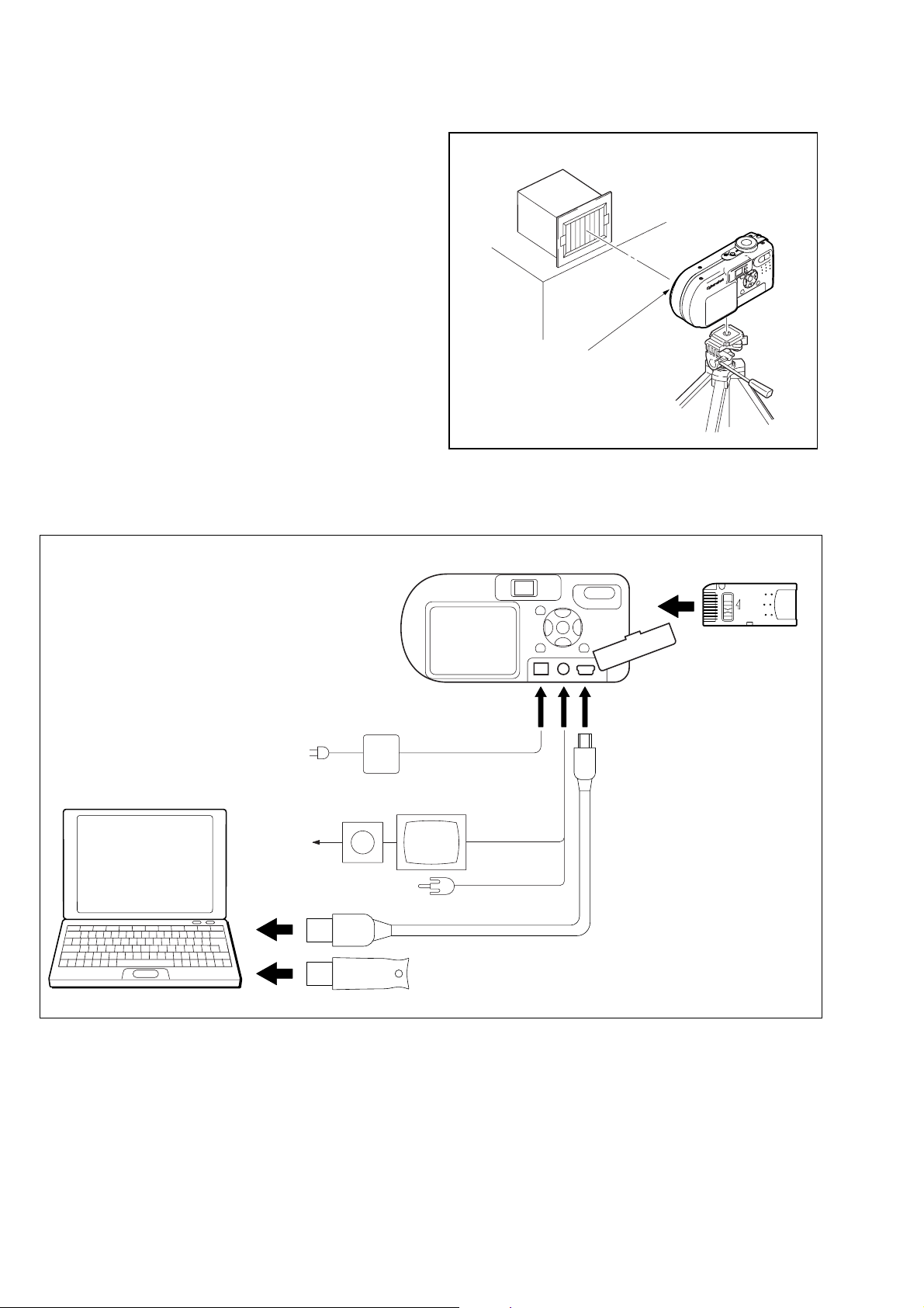
1-1-2. Preparations
1) Connect the equipment for adjustments according to Fig. 6-1-3.
2) Start up the application for adjustment (SEUS).
Note 1: Setting the “Forced CAMERA mode power ON Mode”
1) Select page: 00, address: 01, and set data: 01.
2) Select page: 2F, address: 21, and write data 03.
The above procedure will enable the camera power
to be turned on. After completing adjustments, be
sure to exit the “Forced CAMERA mode power ON
Mode”.
Note 2: Exiting the “Forced CAMERA mode power ON Mode”
1) Select page: 00, address: 01, and set data: 01.
2) Select page: 2F, address: 21, and write data: 00.
3) Select page: 00, address: 01, and set data: 00.
Pattern box
L
Front of the lens
L = About 25 cm
Fig. 6-1-2
PC
with USB connectors (x 2)
(Windows 98/98SE/ME/2000/XP)
AC IN
Vectorscope
Terminated
75 Ω
To USB connector
To USB connector
AC power adaptor
Color monitor
DSC-P10/P12
To DC IN jack
Video (yellow)
Audio (Black)
HASP Key
Insert the Memory Stick
and the Batteries*.
LOCK
To USB connector
To A/V OUT
jack
USB cable
(1-823-932-11)
Fig. 6-1-3
6-4
Page 7
DSC-P10/P12
1-1-3. Discharging of the Flashlight Power Supply
The capacitor which is used as power supply of flashlight is charged
with 200 V to 300 V voltage. Discharge this voltage before starting adjustments in order to protect service engineers from electric
shock during adjustment.
Discharge procedure
1. Press the FLASH button (SW-386 board S004 (CONTROL
UP)) and set the NO FLASH mode.
2. Fabricate the discharging jig as shown in Fig. 6-1-5 locally by
yourself. Connect the discharging jig to the positive (+) and
negative (–) terminal of the flash v oltage charge capacitor . Allow ten seconds to discharge the voltage.
Capacitor
ST-81
R:1 kΩ/1 W
(Part code:
1-215-869-11)
Fig. 6-1-4
Fig. 6-1-5
1 kΩ/1 W
Wrap insulating tape.
6-5
Page 8
DSC-P10/P12
1-1-4. Precautions
1. Setting the Switch
Unless otherwise specified, set the switches as follows and perform adjustments.
1. Mode Dial .......................................... CAMERA
2. ZOOM switch
(SW-386 board S001, S002).............. WIDE end
3. EV (Menu display) ............................ 0EV
4. DISPLAY/LCD ON/OFF button
(SW-386 board S005) ........................ OSD OFF
5. WB (WHITE BALANCE)
(Menu display) ................................... AUTO
6. P.EFFECT (Menu display) ................ OFF
7. VIDEO OUT (SET UP setting)......... NTSC
2. Order of Adjustments
Basically carry out adjustments in the order given.
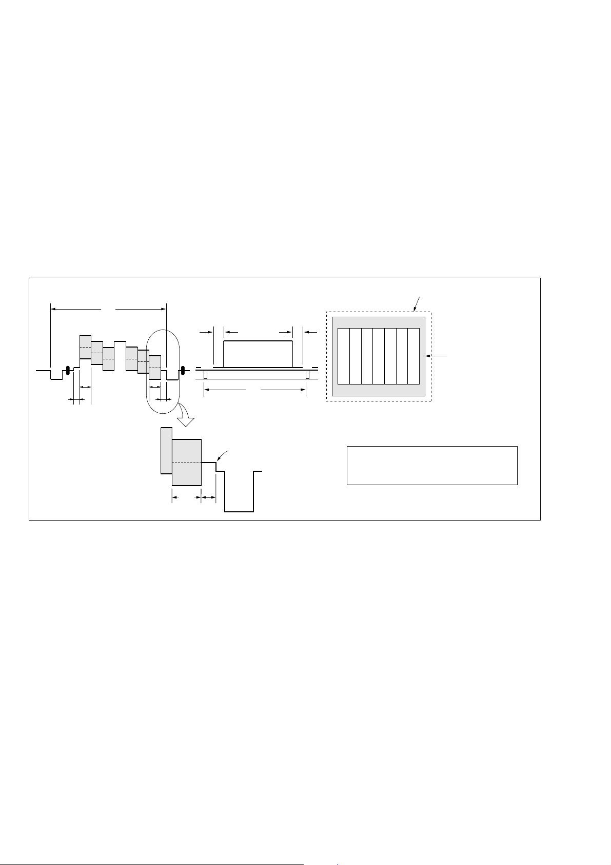
Color bar chart (Standard picture frame)
H
Yellow
Cyan
White
Magenta
Green
BB
A=B/2A
Fig. a
(VIDEO terminal of A/V jack
output waveform)
Red
Blue
A
Enlargement
B
A
Difference in level
3. Subjects
1) Color bar chart (Standard picture frame).
When performing adjustments using the color bar chart, adjust the picture frame as shown in Fig. 6-1-6. (Standard picture frame)
2) Clear chart (Standard picture frame)
Remove the color bar chart from the pattern box and insert a
clear chart in its place. (Do not perform zoom operations during this time)
C=D
V
Fig. 6-1-6
Electronic beam scanning frame
DC
Red
Cyan
White
Green
Yellow
Fig. b (monitor TV picture)
Adjust the camera zoom and direction to
obtain the output waveform shown in Fig a
and the monitor TV display shown in Fig. b.
Magenta
Blue
CRT picture frame
6-6
Page 9
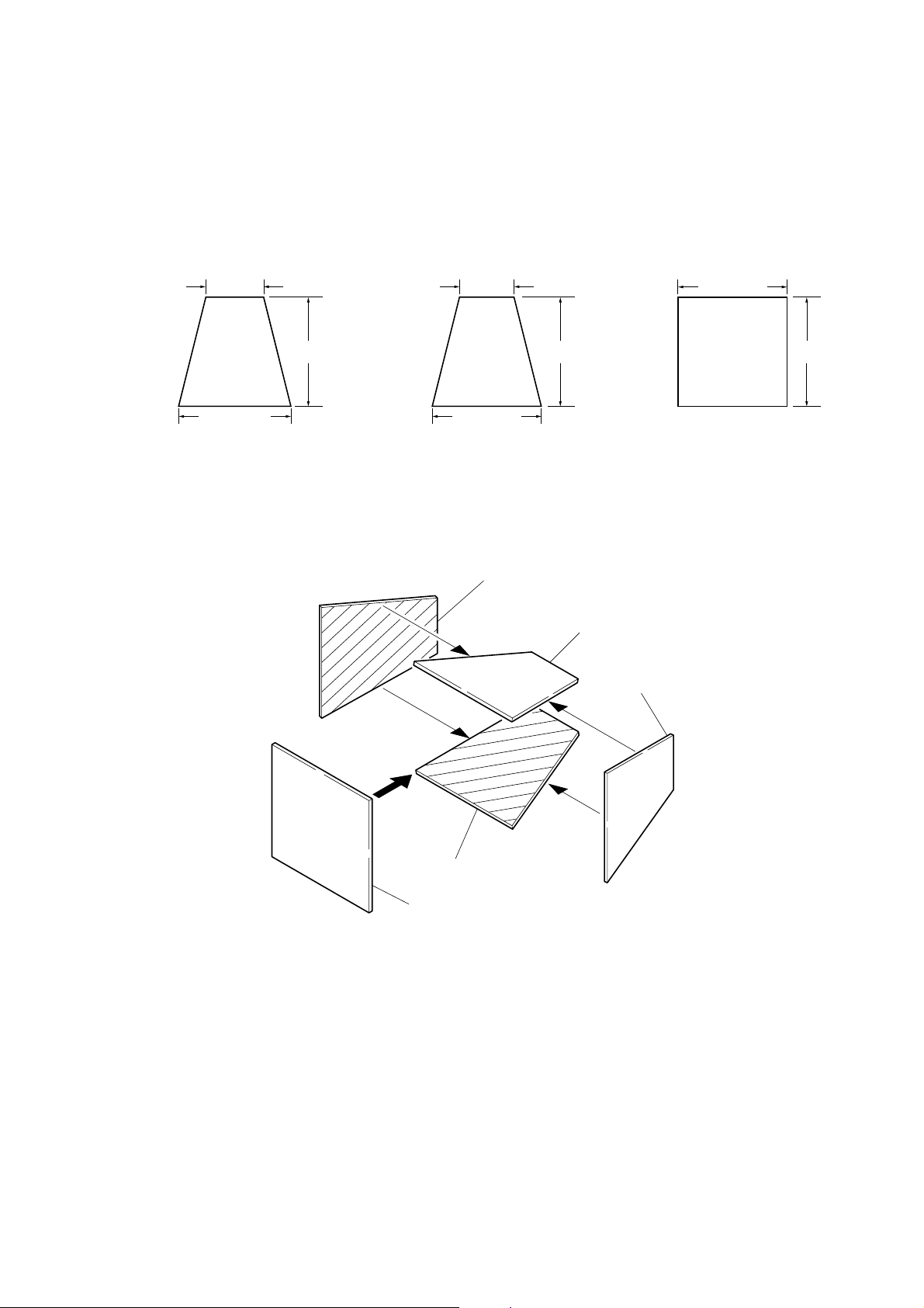
4. Preparing the Flash Adjustment Box
A dark room is required to provide an accurate flash adjustment.
If it is not available, prepare the flash adjustment box as given
below;
1) Provide woody board A, B and C of 15 mm thickness.
DSC-P10/P12
woody board A (2)
400 mm
513 mm 513 mm 700 mm
woody board B (2)
Fig. 6-1-7
2) Apply black mat paint to one side of woody board A and B.
3) Attach background paper (J-2501-130-A) to woody board C.
4) Assemble so that the black sides and the background paper
side of woody board A, B and C are internal. (Fig. 6-1-8)
370 mm
700 mm730 mm
woody board A
woody board C (1)
700 mm
woody board B
woody board A
woody board B
woody board C
Fig. 6-1-8
6-7
Page 10
DSC-P10/P12
COVER
COVER
1-2. INITIALIZATION OF 0E, 2F, 4F, 6F PAGE
DAT A
1-2-1. Initialization of 0E, 2F, 4F, 6F Page Data
1. Initializing 0E, 2F, 4F, 6F Page Data
Note 1: Initialize the data every page of 0E, 2F, 4F, and 6F.
Note 2: If the 4F page data has been initialized, the following
adjustments need to be performed again.
1) Video system adjustment
2) LCD system adjustments
Note 3: If the 6F page data has been initialized, the following
adjustments need to be performed again.
1) Camera system adjustments
Adjusting Page 0E
Adjusting Address 00 to FF
Adjusting Page 2F
Adjusting Address 00 to 7F
Adjusting Page 4F
Adjusting Address 00 to FF
Adjusting Page 6F
Adjusting Address 00 to FF
Initializing Method:
1) Click [Page Edit] on the SEUS screen to display the SEUS
PAGE EDIT screen.
2) Click [Page], and then enter the page to be initialized.
3) Click [Preset Data Read] to display the Set ID input screen.
4) For page 0E, enter Set ID = “00” and read the initializing data
on the SEUS PAGE EDIT screen.
5) For page 2F, 4F and 6F, enter Set ID = “06” and read the initializing data on the SEUS PAGE EDIT screen.
6) On the SEUS PAGE EDIT screen, change the data at “Fixed
data-2” address given in the table on the page to be initialized.
Note: New data for change are not listed in the table. If the
data are to be changed, read and copy the data from the
same model. Copying the data from different models
may cause an operation failure.
7) Confirm that the data at respective adjustment addresses are
the initial values (adjustment initial values) given in the table.
If different, change to the adjustment initial values.
8) Click
9) Click [Close] to close the SEUS PAGE EDIT screen.
Processing after Completing Initializing
Order Page
Note: At this time, the set is reset and the power is turns off once
[Write] to write the initializing data to the set.
Address
12F2104 [Write]
2200029 [set]
3200129 [Write] (Note)
and then on again. Accordingly, the message “Receive
Packet Error” is displayed on the SEUS screen, and the
SEUS goes in “disconnect” state, but this is not a trouble.
Click
[Connect] on the SEUS screen to restore the “con-
nected” state.
Data Procedure
2. 0E Page table
Note 1: Fixed data-1: Initialized data.
(Refer to step 4 of “ 1. Initializing of 0E, 2F , 4F, 6F Page
Data”)
Note 2: Fixed data-2: Modified data.
(Refer to step 6 of “ 1. Initializing of 0E, 2F , 4F, 6F Page
Data”)
Address Initial value Remark
00 to FF Fixed data-1 (Initialized data)
3. 2F Page table
Note 1: Fixed data-1: Initialized data.
(Refer to step 5 of “ 1. Initializing of 0E, 2F , 4F, 6F Page
Data”)
Note 2: Fixed data-2: Modified data.
(Refer to step 6 of “ 1. Initializing of 0E, 2F , 4F, 6F Page
Data”)
Address Initial value Remark
00 to 20 Fixed data-1 (Initialized data)
21 00 Test mode
22 to 7F Fixed data-1 (Initialized data)
4. 4F Page table
Note 1: Fixed data-1: Initialized data.
(Refer to step 5 of “ 1. Initializing of 0E, 2F , 4F, 6F Page
Data”)
Note 2: Fixed data-2: Modified data.
(Refer to step 6 of “ 1. Initializing of 0E, 2F , 4F, 6F Page
Data”)
Address Initial value Remark
00 to 81 Fixed data-1 (Initialized data)
82 90 VCO adj. (NTSC mode)
83 9A VCO adj. (PAL mode)
84 91 V-COM adj.
85 AF Bright adj.
86 2D Black limit adj.
87 Fixed data-1 (Initialized data)
88 8C
89 6C
8A 42 Contrast adj.
8B to 9F Fixed data-1 (Initialized data)
A0 80 Video sync level adj.
A1 to A7 Fixed data-1 (Initialized data)
A8 Fixed data-2
A9 Fixed data-2
AA to FF Fixed data-1 (Initialized data)
White balance adj.
6-8
Page 11
DSC-P10/P12
5. 6F Page Table
Note 1: Fixed data-1: Initialized data.
(Refer to step 5 of “ 1. Initializing of 0E, 2F , 4F, 6F Page
Data”)
Note 2: Fixed data-2: Modified data.
(Refer to step 6 of “ 1. Initializing of 0E, 2F , 4F, 6F Page
Data”)
Address Initial value Remark
00 to 0F Fixed data-1 (Initialized data)
10 FF
11 FF
12 FF
13 FF
14 00
15 90
16 FF
17 FF
18 34
19 F5
1A 87
1B 71
1C 10
1D 47
1E 00
1F 00
20 00
21 00
22 00
23 00
24 20
25 20
26 13
27 46
28 0A
29 00 Flange back adj.
2A 00
2B 00
2C 00
2D 00
2E 00
2F 00
30 00
31 00
32 00
33 00
34 00
35 00
36 00
37 00
38 00
39 00
AF Ilumination check.
Address Initial value Remark
3A 00
3B 00
3C 00
3D 00
3E FF
3F Fixed data-1 (Initialized data)
40 00
41 00
42 00
43 00
44 00
45 00
46 00
47 00
48 00
49 00
4A 00
4B 00
4C 00
4D 00
4E 00
4F 00
50 00
51 00
52 00
53 00
54 to 5F Fixed data-1 (Initialized data)
60 00
61 00
62 00 F No. compensation
63 00
64 00
65 30
66 FE Light value adj.
67 6D
68 to 6A Fixed data-1 (Initialized data)
6B FF
6C 00
6D 00
6E 00
6F 00
70 29
71 83
72 1F
73 DF AWB 3200K standard data input
74 29
75 0C
76 22
Flange back adj.
Flange back adj.
F No. compensation
Mechanical shutter adj.
Mixed color calcel adj.
6-9
Page 12
DSC-P10/P12
Address Initial value Remark
77 6D
78 00
79 00
7A 00
7B 00
7C 00
7D 00
7E 00
7F 00 AWB 3200K standard data input
80 00
81 00
82 00
83 00
84 00
85 00
86 00
87 00
88 19
89 66
8A 30
8B 6E
8C 19
8D A7
8E 32
8F FB
90 00
91 00
92 00
93 00
94 00
95 00
96 00
97 00
98 00
99 00
9A 00
9B 00
9C 00
9D 00
9E 00
9F 00
A0 2A
A1 80
A2 5E
A3 C0
A4 03
A5 E9 Color reproduction adj.
A6 63
AWB 5800K standard data input
Address Initial value Remark
A7 83
A8 D5
A9 FE
AA 73
AB 45 Color reproduction adj.
AC 63
AD 83
AE 03
AF E9
B0 00 AWB 3200K standard data input
B1 00 AWB 5800K standard data input
B2 00 AWB 3200K standard data input
B3 00 AWB 5800K standard data input
B4 00 AWB 3200K standard data input
B5 Fixed data-1 (Initialized data)
B6 28
B7 6E
B8 10
B9 37
BA 10
BB 37
BC 00
BD 00
BE 00
BF 00
C0 00
C1 00
C2 00
C3 00
C4 00
C5 00
C6 00
C7 28 Mechanical shutter adj.
C8 1B
C9 00
CA 00
CB 00
CC 80
CD 88
CE 98
CF 90
D0 88
D1 00
D2 00
D3 00
D4 00
D5 00
D6 00
Strobe balance adj.
6-10
Page 13

Address Initial value Remark
D7 14 Mechanical shutter adj.
D8 FF
D9 FF
DA FF
DB 00
DC 00
DD 00
DE 00
DF 00
E0 00
E1 00
E2 00
E3 00
E4 00
E5 00
E6 00
E7 00
E8 00
E9 00
EA 00
EB 00
EC 00
ED 00
EE 00
EF 00
F0 to FF Fixed data-1 (Initialized data)
Strobe balance adj.
DSC-P10/P12
6-11
Page 14

DSC-P10/P12
COVER
COVER
1-3. VIDEO SYSTEM ADJUSTMENTS
1. Composite Video Level Adjustment
Adjust the sync level of the composite video signal output and
check the burst level of the composite video signal output.
Mode PLAY
Signal Arbitrary
Measurement Point Video terminal of A/V OUT jack
(75 Ω terminated)
Measuring Instrument Oscilloscope
Adjustment Page 4F
Adjustment Address A0
Specified Value Sync level:
A = 286 ± 5 mV (NTSC mode)
A = 300 ± 5 mV (PAL mode)
Burst level:
B = 286 ± 30 mV (NTSC mode)
B = 300 ± 30 mV (PAL mode)
Note: Check that the data of page: 60, address: C1 is “01”.
If not, turn the power of unit OFF/ON.
Adjusting method:
Order Page
1000101 [Set]
24F0203 [Set]
340F104 [Set]
44FA0
54FA0[Write]
6
Processing after Completing Adjustments:
Order Page
14F0200 [Set]
240F100 [Set]
3000100 [Set]
Address
Address
Data Procedure
Change the data and set
the sync level (A) to the
specified value.
Check the burst level (B)
to the specified value.
Data Procedure
B
A
H
Fig. 6-1-9
6-12
Page 15

COVER
COVER
DSC-P10/P12
1-4. CAMERA SYSTEM ADJUSTMENTS
Before perform the camera system adjustments, check that the
specified values of “VIDEO SYSTEM ADJUSTMENTS” are satisfied.
Note: For “CAMERA SYSTEM ADJUSTMENTS”, perform in
order of item numbers.
Data setting during camera system adjustments
Perform the following data setting before the camera system adjustments.
It is not necessary to perform the following data setting ever ytime
when you perform some items of camera system adjustments continuously unless the power is turned off. Only when the power is
turned off during this adjustments, perform the data setting again,
then continue the adjustments.
Set up setting:
1) VIDEO OUT of SET UP setting............... NTSC (NTSC mode)
(This adjustment must be performed in NTSC mode, so don't
set the SET UP setting to “PAL”)
Data setting method
Order Page
1000101 [Set]
26F0020 [Write]
34F0120 [Write]
47F6800 [Write]
5200029 [Set]
6200129 [Write] (Note 1)
7000101 [Set]
84F0F01 [Write]
92F2103 [Write]
10 60 C1 [Read]
11 4F 02 02 [Set]
12 60 6C 01 [Set]
13 60 2C 01 [Set]
14 Wait for 1 second.
Note 1: At this time, the set is reset and the power is turned off
Note 2: Repeat the “Data setting method”, if the power was turned
Address
once and then on again. Accordingly, the message “Receive Packet Error” is displayed on the SEUS screen, and
the SEUS goes in “disconnect” state, but this is not a
trouble. Click
the “connected” state. (In case that the power does not
turn on again, press the power button.)
off and on during the “CAMERA SYSTEM ADJUSTMENTS”.
Data Procedure
Check the data changes
to “02”.
[Connect] on the SEUS screen to restore
After completing the camera system adjustments, release the
data setting:
1) Click [Page Edit] on the SEUS screen to display the SEUS
PAGE EDIT screen.
2) Click
3) Click
4) Enter Set ID = “00” and read the initializing data on the SEUS
5) Check that all the data is “FF”.
6) Click [Write] to write the initializing data to the set.
7) Click [Close] to close the SEUS PAGE EDIT screen.
8) Release the data setting which has been executed before ad-
Order Page
[Page], and then enter the page “0E”.
[Preset Data Read] to display the Set ID input screen.
PAGE EDIT screen.
justment.
Address
14F0100 [Write]
27F6840 [Write]
3602C00 [Set]
4606C00 [Set]
54F0200 [Set]
62F2100 [Write]
74F0F00 [Write]
8000100 [Set]
Data Procedure
6-13
Page 16

DSC-P10/P12
E=F
V
EF
Picture Frame Setting
Mode CAMERA
Subject Color bar chart
(Standard picture frame with the
zoom lens at WIDE end)
Measurement Point Video terminal of A/V OUT jack
(75 Ω terminated)
Measuring Instrument Oscilloscope and monitor TV
Specified value A=B/2, C/2=D, E=F
Switch setting:
1) FOCUS (Menu setting)................. Multi AF
2) MACRO (Control button)............. ON
Setting method:
Order Page
Address
Data Procedure
Shoot the color bar chart
1
with the zoom WIDE
end.
2608C30 [Set]
Enter the output of
VIDEO OUT to the
3
monitor TV, and move
the position as shown in
Fig. 6-1-12.
Horizontal width of
black (A, D) on the color
4
bar chart should be a half
of that of one color bar
(B, C). (See Fig. 6-1-10)
With vertical width of
black (E, F) set in same,
5
the color bar chart
should come to the
center of monitor TV.
(See Fig. 6-1-11)
Check that the color bar
6
on the monitor TV is
focused.
Read the data.
71044
[Read]
Note down the data, and
this is named YH data.
Read the data.
81045
[Read]
Note down the data, and
this is named YL data.
How to reset the zoom and focus when they deviated:
Order Page
Address
Data Procedure
1609000 [Set]
2609100 [Set]
36092YL [Set] (Note 2)
46093YH [Set] (Note 2)
5600179 [Write]
66007[Read]
7600100
[Write]
Check the data changes
to “01”.
Note 2: The data noted down at step 6 and 7 of “Setting method”.
Check on the oscilloscope
1. Horizontal period
A=B/2
B
A
C/2=D
C
D
Fig. 6-1-10
2. Vertical period
Fig. 6-1-11
Processing after Completing Adjustments:
Order Page
1608C00
Address
Data Procedure
[Set]
Check on the monitor TV
Color bar chart picture frame
6-14
Monitor TV picture frame
Fig. 6-1-12
Page 17

DSC-P10/P12
1. Flange Back Adjustment
(Using the minipattern box)
The flange back of inner focus lens is adjusted automatically. If
shifted, the auto focus is disordered.
Mode CAMER
Subject Siemens star chart with ND filter
for minipattern box (Note 1)
Measurement Point Check operation on monitor TV
Measuring Instrument
Adjustment Page 6F
Adjustment Address 18 to 3E, 40 to 53
Specified value 1 00
Specified value 2 0A to 40
Note 1: Dark Siemens star chart.
Note 2: Check that the data of page: 60, address: 02 is “00”. If
not, press the RESET switch using a thin and long pin.
Caution:
If the video lens or SY-83 board was replaced, make a setting
by referring to “Precaution on Replacing the Video Lens or the
SY-83 Board” and then perform the adjustment.
Preparations before adjustments:
1) The minipattern box is installed as shown in the following figure.
Note 3: The attachment lenses are not used.
Note 4: Take care not to hit the mini-pattern box when ex-
tending the lens.
2) Install the minipattern box so that the distance between it and
the front of lens of camera is less than 3 cm.
3) Make the height of minipattern box and the camera equal.
4) Check the output voltage of the regulated power supply is the
specified voltage ± 0.01 Vdc.
5) Check that the center of Siemens star chart meets the center of
shot image screen with the zoom lens at TELE end and WIDE
end respectively.
Specified voltage:The specified voltage varies according to the
minipattern box, so adjustment the power supply output voltage to the specified voltage written on the sheet which is supplied with the minipattern box.
Below 3 cm
Adjusting method:
Order Page
Address
Data Procedure
Perform “Data setting
1
during camera sysem
adjustment”.
(Refer to page 6-13)
2600113 [Write]
3600127 [Write] (Note 5)
46002
[Read]
Check the data changes
to “01”.
Check that the data
56F3E
[Read]
satisfied the specified
value 1.
Check that the data
66F24
[Read]
satisfied the specified
value 2.
7600100 [Write]
8600125 [Write]
9Wait for 3 seconds.
Note 5: The adjustment data will be automatically input to page:
6F, address: 18 to 3E and 40 to 53.
Processing after Completing Adjustments:
Order Page
Address
Data Procedure
1600100 [Write]
2
Perform “Flange Back
Check “.
[Precaution on Replacing the Video Lens or the SY-83
Board]
The DSC-P10/P12 uses the position sensor to detect the zoom position.
Accordingly, the zoom position will vary if the position data
changes due to the replacement of the video lens or the SY-83
board, thus causing the video lens to collide against the mechanism end when the power is turned off.
Though the position data is calibrated at the “Flange Back Adjustment”, add the following work when making an adjustment at the
replacement of video lens to prevent a collision of video lens.
Minipattern box
Output voltage : Specified voltage ± 0.01 Vdc
Red (+)
Black (–)
Yellow (SENS +)
White (SENS –)
Black (GND)
Camera
Camera
table
Regulated power supply
Output current : more than 3.5 A
Need not connected
Fig. 6-1-13
When Replacing the Video Lens
1) With current video lens assembled, turn the power on, and set
the data of page: 6F , address: 3E to “FF”, then tur n the power
off.
2) Replace the video lens with a new one, turn the power on, and
perform the “Flange Back Adjustment”.
Thus, new position data will be written.
When Replacing the SY-83 Board
1) Replace the SY-83 board with a new one, set the mode dial to
“PLAY”, turn the power on, and set the data of page: 6F,
address:3E to “FF”, then turn the power off.
2) Set the mode dial to “CAMERA”, turn the power on, and perform the “Flange Back Adjustment”.
Thus, new position data will be written.
6-15
Page 18

DSC-P10/P12
2. Flange Back Check
Mode CAMERA
Subject Siemens star
(1.0 m from the front of the lens)
(Luminance: 200 to 400 lux)
Measurement Point Check operation on monitor TV
Measuring Instrument
Specified value Focused at the TELE end and
WIDE end
Checking method:
Order Page
1
2
3
4608C30 [Set]
55F3D50 [Set] (Note 1)
67B9894 [Set]
7
8
9602C01 [Set]
10
Note 1: How to find the data
Address
Decrease the data of page: 5F , address: 3D until four sides
of a black frame can be seen on the monitor, then find
the value. The largest value under this condition will be
the seting value. If the value is less than 50, change
monitorrs.
Data Procedure
“Flange Back Adjustment” is completed.
Place the Siemens star
1.0 from the front of the
lens.
To open the IRIS,
decrease the luminous
intensity to the Siemens
star up to a point before
noise appear on the
image.
Set the zoom lens to the
TELE end then set the
center of the Siemens
star chart in the center of
the TV monitor.
Check that the lens is
focused.
While observe the TV
monitor, change the
zoom to the WIDE end
and check that the lens is
focused.
3. F No. Compensation
Compensate the unevenness of the iris meter sensitivity.
Mode CAMERA
Subject Clear chart
(Standard picture frame with the
zoom lens at WIDE end)
Measurement Point Data of page: 6F, address: 6B
Adjustment Page 6F
Adjustment Address 60 to 64, 6B to 6D
Specified value 00
Note 1: Check that the data of page: 60, address: 02 is “00”. If
not, press the RESET switch using a thin and long pin.
Adjusting methd:
Order Page
1
2
36001BB [Write] (Note 2)
46002
56F6B
Note 2: The adjustment data will be automatically input to page:
Processing after Completing Adjustments:
Order Page
1600100 [Write]
2
Address
6F, address: 60 to 64 and 6B to 6D.
Address
Data Procedure
Perform “Data setting
during camera system
adjustment”.
(Refer to page 6-13)
Perform “Picture frame
setting”
(Refer to page 6-14)
[Read]
[Read]
Data Procedure
Check the data changes
to “01”.
Check that the data
satisfied the specified
value.
Release “Data setting
during camera system
adjustment”
(Refer to page 6-13)
Processing after Completing Adjustments:
Order Page
15F3D[Read]
2608C00 [Set]
37B98[Read]
4
Address
Data Procedure
Release “Data setting
during camera system
adjustment”
(Refer to page 6-13)
6-16
Page 19

DSC-P10/P12
4. Mechanical Shutter Adjustment
Adjust the period which the mechanical shutter is closed, and compensate the exposure.
Mode CAMERA
Subject Clear chart
(Standard picture frame with the
zoom lens at WIDE end)
Measurement Point Data of page: 6F, address: 6B
Adjustment Page 6F
Adjustment Address 6B to 6D, B8 to D7
Specified value 00
Note 1: Check that the data of page: 60, address: 02 is “00”. If
not, press the RESET switch using a thin and long pin.
Adjusting method:
Order Page
1 Perform “Data setting
2
36001AD [Write] (Note 2)
46002
56F6B
Note 2: The adjustment data will be automatically input to page:
Processing after Completing Adjustments:
Order Page
1600100 [Write]
2
Address
6F, address: 6B to 6D and 8B to D7.
Address
Data Procedure
during camera system
adjustment”.
(Refer to page 6-13)
Perform “Picture frame
setting”
(Refer to page 6-14)
[Read]
[Read]
Data Procedure
Check the data changes
to “01”.
Check that the data
satisfied the specified
value.
Release “Data setting
during camera system
adjustment”
(Refer to page 6-13)
5. Light Value Adjustment
Adjust the standar light value.
Mode CAMERA
Subject Clear chart
(Standard picture frame with the
zoom lens at WIDE end)
Measurement Point Data of page: 10, address: 0C and
0D (2byte data) (Note 2)
Data of page: 6F, address: 65
Adjustment Page 6F
Adjustment Address 65 to 67
Specified value 1 0FE0 to 1020
Specified value 2 36 to 4E
Note 1: Check that the data of page: 60, address: 02 is “00”. If
not, press the RESET switch using a thin and long pin.
Note 2: 2byte data is upper 1byte data and lower 1 byte data.
XX XX
Lower 1byte data (Page: 10, adderss: 0D)
Upper 1byte data (Page: 10, adderss: 0C)
Adjusting method:
Order Page
1
2
360010D [Write] (Note 3)
46002
5100C
6100D
7
86F65
Note 3: The adjustment data will be automatically input to page:
Address
[Read]
[Read]
[Read]
[Read]
6F, address: 65 to 67.
Data Procedure
Perform “Data setting
during camera system
adjustment”.
(Refer to page 6-13)
Perform “Picture frame
setting”
(Refer to page 6-14)
Check the data changes
to “01”.
Read the data
(Upper 1byte).
Read the data
(Lower 1byte).
Check that the 2byte
data (Note 2) satisfied
the specified value 1.
Check that the data
satisfied the specified
value 2.
Processing after Completing Adjustments:
Order Page
1600100 [Write]
2
Address
Data Procedure
6-17
Release “Data setting
during camera system
adjustment”
(Refer to page 6-13)
Page 20

DSC-P10/P12
6. Mixed Color Cancel Adjustment
Correct the dispersion of Gr/Gb filter on CCD imager
Mode CAMERA
Subject Color bar chart
(Standard picture frame with the
zoom lens at WIDE end)
Adjustment Page 6F
Adjustment Address 6E and 6F
Specified value 00
Note 1: Check that the data of page: 60, address: 02 is “00”. If
not, press the RESET switch using a thin and long pin.
Adjusting method:
Order Page
1
2
36FB5FF [Write]
46001D7 [Write]
5Wait for 3 seconds.
66001D5 [Write] (Note 2)
76002
86FB5
Note 2: The adjustment data will be automatically input to page:
Processing after Completing Adjustments:
Order Page
1600100 [Write]
2
Address
Data Procedure
[Read]
[Read]
6F, address: 6E and 6F
Address
Data Procedure
Perform “Data setting
during camera system
adjustment”.
(Refer to page 6-13)
Perform “Picture frame
setting”
(Refer to page 6-14)
Check the data changes
to “01”.
Check that the data
satisfied the specified
value.
Release “Data setting
during camera system
adjustment”
(Refer to page 6-13)
7. AWB 3200K Standard Data Input
Adjust the white balance reference at 3200K.
Mode CAMERA
Subject Clear chart
(Standard picture frame with the
zoom lens at WIDE end)
Adjustment Page 6F
Adjustment Address 70 to 87, B0, B2, and B4
Specified value 00
Note 1: Check that the data of page: 60, address: 02 is “00”. If
not, press the RESET switch using a thin and long pin.
Adjusting method:
Order Page
1
2
36FB5FF [Write]
460010B [Write] (Note 2)
56002
66FB5
Note 2: The adjustment data will be automatically input to page:
Processing after Completing Adjustments:
Order Page
1600100 [Write]
2
Address
6F, address: 70 to 87, B0, B2 and B4.
Address
Data Procedure
Perform “Data setting
during camera system
adjustment”.
(Refer to page 6-13)
Perform “Picture frame
setting”
(Refer to page 6-14)
[Read]
[Read]
Data Procedure
Check the data changes
to “01”.
Check that the data
satisfied the specified
value.
Release “Data setting
during camera system
adjustment”
(Refer to page 6-13)
6-18
Page 21

DSC-P10/P12
8. AWB 5800K Standard Data Input
Adjust the white balance reference at 5800K.
Mode CAMERA
Subject Clear chart
(Standard picture frame with the
zoom lens at WIDE end)
Filter Filter C14 for color temperature
correction
Adjustment Page 6F
Adjustment Address 88 to A3, B1, and B3
Specified value 00
Note 1: Check that the data of page: 60, address: 02 is “00”. If
not, press the RESET switch using a thin and long pin.
Note 2: Perform this check after “AWB 3200K Standard Data
Input” without a break.
Adjusting method:
Order Page
1
2
3
46FA028 [Write]
56FA1B0 [Write]
66FA25E [Write]
76FA380 [Write]
86FB5FF [Write]
96001A5 [Write] (Note 3)
10 60 02
11 6F B5
Note 3: The adjustment data will be automatically input to page:
Address
6F, address: 88 to A3, B1 and B3.
Data Procedure
Place the C14 filter on
the lens.
Perform “Data setting
during camera system
adjustment”.
(Refer to page 6-13)
Perform “Picture frame
setting”
(Refer to page 6-14)
[Read]
[Read]
Check the data changes
to “01”.
Check that the data
satisfied the specified
value.
9. AWB 5800K Check
Mode CAMERA
Subject Clear chart
(Standard picture frame with the
zoom lens at WIDE end)
Filter Filter C14 for color temperature
correction
Measurement Point Data of page: 6F, address: B5
Specified value 00
Note: Check that the data of page: 60, address: 02 is “00”. If not,
press the RESET switch using a thin and long pin.
Checking method:
Order Page
1
2
3
46FB5FF [Write]
560013F [Write]
66002[Read]
76FB5
Processing after Completing Adjustments:
Order Page
1600100 [Write]
2
Address
Address
Data Procedure
Place the C14 filter on
the lens.
Perform “Data setting
during camera system
adjustment”.
(Refer to page 6-13)
Perform “Picture frame
setting”
(Refer to page 6-14)
Check the data changes
to “01”.
Check that the data
[Read]
Data Procedure
satisfied the specified
value.
Release “Data setting
during camera system
adjustment”
(Refer to page 6-13)
Processing after Completing Adjustments:
Order Page
1600100 [Write]
2
Address
Data Procedure
Release “Data setting
during camera system
adjustment”
(Refer to page 6-13)
6-19
Page 22

DSC-P10/P12
10. AWB 3200K Check
Mode CAMERA
Subject Clear chart
(Standard picture frame with the
zoom lens at WIDE end)
Measurement Point Data of page: 6F, address: B5
Specified value 00
Note: Check that the data of page: 60, address: 02 is “00”. If not,
press the RESET switch using a thin and long pin.
Checking method:
Order Page
Address
Data Procedure
Perform “Data setting
1
during camera system
adjustment”.
(Refer to page 6-13)
Perform “Picture frame
2
setting”
(Refer to page 6-14)
36FB5FF [Write]
460010F [Write]
56002 [Read]
Check the data changes
to “01”.
Check that the data
66FB5
[Read]
satisfied the specified
value. (Note 2)
Processing after Completing Adjustments:
Order Page
Address
Data Procedure
1600100 [Write]
Release “Data setting
2
during camera system
adjustment”
(Refer to page 6-13)
11. CCD Linearity Check
Check that CCD output keep being staraight even ISO sensitivity
is changed.
Mode CAMERA
Subject Clear chart
(Standard picture frame with the
zoom lens at WIDE end)
Specified value 1 96 to 104 (Decimal)
Specified value 2 96 to 104 (Decimal)
Note: 2byte data is upper 1byte data and lower 1byte data.
XX XX
Lower 1byte data
(Page: 10, address: 81 or 83)
Upper 1byte data
(Page: 10, address: 80 or 82)
Checking method:
Order Page
Address
Data Procedure
Perform “Data setting
1
during camera system
adjustment”.
(Refer to page 6-13)
Perform “Picture frame
2
setting”
(Refer to page 6-14)
3750904 [Set]
4601F80 [Set]
577F202 [Set]
660129F [Set]
7601490 [Set]
8600516 [Set]
9752188 [Set]
10 75 22 00 [Set]
11 75 23 BB [Set]
12 75 24 1B [Set]
13 75 25 24 [Set]
14 Wait for 2 seconds.
15 60 01 F9 [Write]
16 60 E1 [Read]
Check the data changes
to “08”.
Read the data
17 10 80
[Read]
(Upper 1byte).
Note down the data, and
this is named D02.
Read the data
18 10 81
[Read]
(Lower 1byte).
Note down the data, and
this is named D03.
19
20 6D 02 D
21 6D 03 D
22 6D 0A D
[Write]
02
[Write]
03
[Write]
02
This 2byte data (Note) is
named D1.
Write the data noted
down at order No. 17.
Write the data noted
down at order No. 18.
Write the data noted
down at order No. 17.
6-20
Page 23

DSC-P10/P12
Order Page
23 6D 0B D
Address
Data Procedure
[Write]
03
Write the data noted
down at order No. 18.
Read the data
24 10 82
[Read]
(Upper 1byte).
Note down the data, and
this is named D06.
Read the data
25 10 83
[Read]
(Lower 1byte).
Note down the data, and
this is named D07.
26
27 6D 06 D
28 6D 07 D
29 6D 0E D
30 6D 0F D
[Write]
06
[Write]
07
[Write]
06
[Write]
07
This 2byte data (Note) is
named D2.
Write the data noted
down at order No. 24.
Write the data noted
down at order No. 25.
Write the data noted
down at order No. 24.
Write the data noted
down at order No. 25.
31 60 01 00 [Write]
32 60 E1 00 [Set]
33 77 72 48 [Set]
34 Wait for 2 seconds.
35 60 01 F9 [Write]
36 60 E1 [Read]
Check the data changes
to “08”.
Read the data
37 10 80
[Read]
(Upper 1byte).
Note down the data, and
this is named D00.
Read the data
38 10 81
[Read]
(Lower 1byte).
Note down the data, and
this is named D01.
39
40 6D 00 D
41 6D 01 D
[Write]
00
[Write]
01
This 2byte data (Note) is
named D3.
Write the data noted
down at order No. 37.
Write the data noted
down at order No. 38.
Read the data
42 10 82 [Read]
(Upper 1byte).
Note down the data, and
this is named D04.
Read the data
43 10 83
[Read]
(Lower 1byte).
Note down the data, and
this is named D05.
44
45 6D 04 D
46 6D 05 D
47 60 01 00
[Write]
04
[Write]
05
[Write]
This 2byte data (Note) is
named D4.
Write the data noted
down at order No. 42.
Write the data noted
down at order No. 43.
Order Page
Address
Data Procedure
48 60 E1 00 [Set]
49 77 72 09 [Set]
50 Wait for 2 seconds.
51 60 01 F9 [Write]
52 60 E1 [Read]
Check the data changes
to “08”.
Read the data
53 10 80
[Read]
(Upper 1byte).
Note down the data, and
this is named D08.
Read the data
54 10 81
[Read]
(Lower 1byte).
Note down the data, and
this is named D09.
55
56 6D 08 D
57 6D 09 D
[Write]
08
[Write]
09
This 2byte data (Note) is
named D5.
Write the data noted
down at order No. 53.
Write the data noted
down at order No. 54.
Read the data
58 10 82
[Read]
(Upper 1byte).
Note down the data, and
this is named D0C.
Read the data
59 10 83
[Read]
(Lower 1byte).
Note down the data, and
this is named D0D.
60
61 6D 0C D
62 6D 0D D
[Write]
0C
[Write]
0D
This 2byte data (Note) is
named D6.
Write the data noted
down at order No. 58.
Write the data noted
down at order No. 59.
63 60 E1 00 [Set]
64 60 01 00 [Write]
65 60 12 00 [Set]
66 60 14 00 [Set]
67 60 1F 00 [Set]
68 60 05 00 [Set]
69 75 21 [Read]
70 75 22 [Read]
71 75 23 [Read]
72 75 24 [Read]
73 75 25 [Read]
74 75 09 [Read]
75 77 F7 [Read]
76 77 F2 [Read]
77 77 72 [Read]
78
79
Convert D3 to decimal
notation, and obtain D3’.
Convert D
to decimal
1
notation, and obtain D1’.
6-21
Page 24

DSC-P10/P12
Order Page
Address
Data Procedure
80
81
82
83 6D 10 S10 [Write]
84 6D 11 S
[Write]
11
85
86
87
88
89
90 6D 12 S12 [Write]
91 6D 13 S
[Write]
13
92
93
94
95
96
Calculate S
using
1
following equations.
(Decimal calculation)
S1=(D3’÷D1’) × 100
Check that the S
1
satisfies the specified
value 1.
Convert S
to hexadeci-
1
mal notation.
The upper 1 byte data of
it is named S
10.
The lower 1 byte data of
it is named S
11.
Write the upper 1 byte
data obtained at order
No. 82.
Write the lower 1 byte
data obtained at order
No. 82.
Convert D
to decimal
4
notation, and obtain D4’.
Convert D
to decimal
2
notation, and obtain D2’.
Calculate S
using
2
following equations.
(Decimal calculation)
S2=(D4’÷D2’) × 100
Check that the S
2
satisfies the specified
value 1.
Convert S
to hexadeci-
2
mal notation.
The upper 1 byte data of
it is named S
12.
The lower 1 byte data of
it is named S
13.
Write the upper 1 byte
data obtained at order
No. 89.
Write the lower 1 byte
data obtained at order
No. 89.
Convert D
to decimal
5
notation, and obtain D5’.
Convert D
to decimal
1
notation, and obtain D1’.
Calculate S
using
3
following equations.
(Decimal calculation)
S3=(D5’÷D1’) × 100
Check that the S
3
satisfies the specified
value 2.
Convert S
to hexadeci-
3
mal notation.
The upper 1 byte data of
it is named S
14.
The lower 1 byte data of
it is named S
15.
Order Page
Address
Data Procedure
Write the upper 1 byte
97 6D 14 S
[Write]
14
data obtained at order
No. 96.
Write the lower 1 byte
98 6D 15 S
[Write]
15
data obtained at order
No. 96.
99
100
Convert D
notation, and obtain D6’.
Convert D
notation, and obtain D2’.
Calculate S
101
following equations.
(Decimal calculation)
S4=(D6’÷D2’) × 100
Check that the S
102
satisfies the specified
value 2.
Convert S
mal notation.
103
The upper 1 byte data of
it is named S
The lower 1 byte data of
it is named S
Write the upper 1 byte
104 6D 16 S16 [Write]
data obtained at order
No. 103.
Write the lower 1 byte
105 6D 17 S
[Write]
17
data obtained at order
No. 103.
Processing after Completing Adjustments:
Order Page
Address
Data Procedure
Release “Data setting
1
during camera system
adjustment”
(Refer to page 6-13)
to decimal
6
to decimal
2
using
4
4
to hexadeci-
4
16.
17.
6-22
Page 25

12. Color Reproduction Adjustment
Adjust the color separation matrix coefficient so that proper color
reproduction is produced.
Mode CAMERA
Subject Color bar chart
(Standard picture frame with the
zoom lens at WIDE end)
Measurement Point Video terminal of A/V OUT jack
(75 Ω terminated)
Data of page: 6F, address: B5
Measuring Instrument Vectorscope
Adjustment Page 6F
Adjustment Address A4 to AF
Specified value 00
Menu setting:
1) VIDEO OUT of SET UP menu
................................. NTSC (NTSC mode)
Note 1: Check that the data of page: 60, address: 02 is “00”. If
not, press the RESET switch using a thin and long pin.
Y
Burst position
DSC-P10/P12
R-Y
M
W
G
B-Y
B
C
Y
R
E
G
Adjusting method:
Order Page
1
2
36FB5FF [Write]
46001AB [Write]
5Wait for 3 seconds.
66001A9 [Write] (Note 2)
76002
86FB5
9
Note 2: The adjustment data will be automatically input to page:
Address
Data Procedure
[Read]
[Read]
6F, address: A4 to AF.
Perform “Data setting
during camera system
adjustment”.
(Refer to page 6-13)
Perform “Picture frame
setting”
(Refer to page 6-14)
Check the data changes
to “01”.
Check that the data
satisfied the specified
value.
Check the each color
luminance point is in
each color reproduction
frame.
Fig. 6-1-14
Processing after Completing Adjustments:
Order Page
1600100 [Write]
2
Address
Data Procedure
Release “Data setting
during camera system
adjustment”
(Refer to page 6-13)
6-23
Page 26

DSC-P10/P12
13. CCD White Defect Compensation
Mode CAMERA
Subject Not required
Measurement Point Data of page: 60, address: 55
Note: Check that the data of page: 60, address: 02 is “00”. If not,
press the RESET switch using a thin and long pin.
Adjusting method:
Order Page
1
27D641E [Set]
37D690D [Set]
460018B [Write]
56002[Read]
66055
7600100 [Write]
87D640F [Set]
97D6960 [Set]
10 60 01 87 [Write]
11 60 02 [Read]
12 60 55
Processing after Completing Adjustments:
Order Page
1600100 [Write]
27D64[Read]
37D69[Read]
4
Address
Address
Data Procedure
Perform “Data setting
during camera system
adjustment”.
(Refer to page 6-13)
Check the data changes
to “01”.
Check the data.
[Read]
[Read]
Data Procedure
00 to 7F: Normal
80 to FF: Defective
Check the data changes
to “01”.
Check the data.
00 : Normal
01 to FF: Defective
Release “Data setting
during camera system
adjustment”
(Refer to page 6-13)
14. CCD Black Defect Compensation
Mode CAMERA
Subject Clear chart
(Standard picture frame with the
zoom lens at WIDE end)
Measurement Point Data of page: 60, address: 55
Note 1: Check that the data of page: 60, address: 02 is “00”. If
not, press the RESET switch using a thin and long pin.
Note 2: Check that there are no dust, no dirt and reflection of the
clear chart.
Note 3: Any subject other than the clear chart should be in the
screen.
Adjusting method:
Order Page
1
27D654C [Set]
3609000 [Set]
4609103 [Set]
5609200 [Set]
6609300 [Set]
7600179 [Write]
8603008 [Set]
96007[Read]
10 60 01 8D [Write]
11 60 02 [Read]
12 60 55
13 60 01 00 [Write]
14 7D 65 5A [Set]
15 60 01 89 [Write]
16 60 02 [Read]
17 60 55
Address
Data Procedure
Perform “Data setting
during camera system
adjustment”.
(Refer to page 6-13)
Check the data changes
to “01”.
Check the data changes
to “01”.
Check the data.
00: Proceed to “Process-
[Read]
[Read]
ing after Completing
Adjustment”
00 to 14 : Normal
15 to FF : Defective
Check the data changes
to “01”.
Check the data.
00 : Normal
01 to FF : Defective
Processing after Completing Adjustments:
Order Page
1600100 [Write]
2603000 [Set]
37D65[Read]
4
Address
Data Procedure
6-24
Release “Data setting
during camera system
adjustment”
(Refer to page 6-13)
Page 27

DSC-P10/P12
15. Strobe Adjustment
Adjust the light value and white balance when strobe light flashed.
Mode CAMERA
Subject Flash adjustment box (Note 2)
(50 cm from the front of lens)
Measurement Point Data of page: 6F, address: DC
and B5
Adjustment Page 6F
Adjustment Address B6, B7 and D8 to EF
Specified value 1 05 to 0B
Specified value 2 00
Note 1: Perform this adjustment in the Flash adjustment box.
Note 2: Refer to “4. Preparing the Flash adjustment box”. (See
page 6-7).
Note 3: “Strobe Adjustment” is available only once after the
power is turned on. If the adjustment is retried, press the
RESET swich using a thin and long pin.
Note 4: Check that the data of page: 60, address: 02 is “00”. If
not, press the RESET switch using a thin and long pin.
Switch setting:
1) FLASH (Control button) .................... ON
Adjusting method:
Order Page
1
2602C01 [Set]
3609000 [Set]
4609100 [Set]
56092FF [Set]
66093FF [Set]
7606C01 [Set]
8600179 [Write]
96007[Read]
10 6F B5 FF [Write]
11 60 01 B9 [Write]
12 60 02
13 6F D8 [Read] Check the data is “00”.
14 60 01 00 [Write]
15 60 ED [Read]
16 60 01 E7 [Write] Check the flashing.
17 60 02
18 6F D8 [Read] Check the data is “00”.
19 6F DC [Read]
20 6F B5
Note 5: The adjustment data will be automatically input to page:
Address
6F, address: B6, B7 and D8 to EF.
Data Procedure
Perform “Data setting
during camera system
adjustment”.
(Refer to page 6-13)
Check the data changes
to “01”.
Check the flashing.
(Note 5)
[Read]
[Read]
[Read]
Check the data changes
to “01”.
Check the data changes
to “02”.
Check the data changes
to “01”.
Check that the data
satisfied the specified
value 1.
Check that the data
satisfied the specified
value 2.
Processing after Completing Adjustments:
Order Page
1600100 [Write]
2609000 [Set]
3609100 [Set]
4609200 [Set]
5609300 [Set]
6602C00 [Set]
7606C00 [Set]
8
Address
Data Procedure
6-25
Release “Data setting
during camera system
adjustment”
(Refer to page 6-13)
Page 28

DSC-P10/P12
16. AF Illumination Check
Check the deviation of optical axis of AF illuminator.
Mode CAMERA
Subject Flash adjustment box (Note 3)
(50 cm from the front of lens)
Measurement Point Displayed data of page: 6F,
address: 10
Adjustment Page 6F
Adjustment Address 10 to 17
Specified value 00
Note 1: Perform checking by making the shooting surface of the
Flash adjustment box perpendicular to the optical axis of
the camera.
Note 2: Perform this checking in the Flash adjustment box.
Restrict external light to enter the Flash adjustment box
as less as possible.
Note 3: Refer to “4. Preparing the Flash adjustment box”. (See
page 6-7).
Switch setting:
1) FOCUS (Menu setting)....................... Multi AF
Adjusting method:
Order Page
1
26001EF [Write] (Note 4)
36002
46F10
Note 4: The adjustment data will be automatically input to page:
Processing after Completing Adjustments:
Order Page
1600100 [Write]
2
Address
[Read]
[Read] Check the data is “00”
6F, adress: 10 to 17.
Address
Data Procedure
Perform “Data setting
during camera system
adjustment”.
(Refer to page 6-13)
Check the data changes
to “01”.
Data Procedure
Release “Data setting
during camera system
adjustment”
(Refer to page 6-13)
6-26
Page 29

COVER
COVER
DSC-P10/P12
1-5. LCD SYSTEM ADJUSTMENTS
Before perform the camera system adjustments, check that the
specified values of “VIDEO SYSTEM ADJUSTMENTS” are satisfied.
Note 1: Taken an extreme care not to destroy the liquid crystal
display module by static electricity when replacing it.
Note 2: Set the LCD BRIGHTENSS (SET UP setting) to the
NORMAL.
1. LCD Initial Data Input
Mode PLAY
Signal Arbitrary
Adjustment Page 4F
Adjustment Address 80 to 8A, 8D, 92, 93, A3, A4
Note: “Memory Stick” must be insertde.
Input method:
1) Select page: 00, address: 01, and set data: 01.
2) Select page: 4F, and write the data gi ven in the follo wing table.
Address Data Remark
80 4E
81 FF
82 90 VCO adjustment (NTSC mode)
83 9A VCO adjustment (PAL mode)
84 91 V-COM adjustment
85 AF Bright adjustment
86 2D Black Limit adjustment
87 41 Fixed value
88 8C
89 6C
8A 42 Contrast adjustment
8D BE
92 2D
93 0E
A3 24
A4 1C
Fixed value
White Blance adjustment
Fixed value
Processing after Completing Input:
1) Select page: 00, address: 01, and set data: 00.
6-27
Page 30

DSC-P10/P12
2. VCO Adjustment (SW-386 Board)
Set the VCO free-run frequency. If deviated, the LCD screen will
be blurred.
Mode PLAY
Signal Arbitrary
Measurement Point Data of page: 40, address: 4F
Adjustment Page 4F
Adjustment Address 82 (NTSC mode)
83 (PAL mode)
Specified value 00
Menu setting:
1) VIDEO OUT of SET UP menu
................................. NTSC (NTSC mode)
(This adjustment must be performed in NTSC mode, so don’t set
the menu setting to “PAL”)
Adjusting method:
Order Page
1000101 [Set]
24F0202 [Set]
34F991C [Set]
4404F01 [Set]
5404E01 [Set]
6404F[Read]
74F991D [Set]
8401D82 [Set]
9404F01 [Set]
10 40 4E 01 [Set]
11 40 4F [Read]
Address
Data Procedure
Check that the data
satisfied the specified
value.
Check that the data
satisfied the specified
value.
3. Bright Adjustment (SW-386 Board)
Set the amplitude of the RGB decoder for driving the LCD to the
specified value.
If deviated, the LCD screen image will be blackish or saturated
(whitish).
Mode PLAY
Signal Arbitrary
Measurement Point Data of page: 40, address: 4F
Adjustment Page 4F
Adjustment Address 85
Specified value 00
Adjusting method:
Order Page
1000101 [Set]
24F0202 [Set]
34F8FAF [Set]
4404F02 [Set]
5404E01 [Set]
6404F[Read]
Processing after Completing Adjustments:
Order Page
14F02[Read]
2000100 [Set]
Address
Address
Data Procedure
Check that the data
satisfied the specified
value.
Data Procedure
Processing after Completing Adjustments:
Order Page
1401D80 [Set]
24F02[Read]
3000100 [Set]
Address
Data Procedure
6-28
Page 31

DSC-P10/P12
4. Contrast Adjustment (SW-386 Board)
Set the level of the VIDEO signal for driving the LCD to the specified value.
If deviated, the LCD screen image will be blackish or saturated
(whitish).
Mode PLAY
Signal Arbitrary
Measurement Point Data of page: 40, address: 4F
Adjustment Page 4F
Adjustment Address 8A
Specified value 00
Note: Perform “Bright Adjustment” before this adjustment.
Adjusting method:
Order Page
1000101 [Set]
24F0202 [Set]
34F9140 [Set]
4404F03 [Set]
5404E01 [Set]
6404F[Read]
Address
Data Procedure
Check that the data
satisfied the specified
value.
5. Black Limit Adjustment (SW-386 Board)
Set the maximum amplitude of the RGB decoder for driving the
LCD to the specified value.
If deviated, the LCD screen image will be blackish or saturated
(whitish).
Mode PLAY
Signal Arbitrary
Measurement Point Data of page: 40, address: 4F
Adjustment Page 4F
Adjustment Address 86
Specified value 00
Note: Perform “Bright Adjustment” before this adjustment.
Adjusting method:
Order Page
1000101 [Set]
24F0202 [Set]
34F9FB5 [Set]
4404F04 [Set]
5404E01 [Set]
6404F[Read]
Address
Data Procedure
Check that the data
satisfied the specified
value.
Processing after Completing Adjustments:
Order Page
14F02[Read]
2000100 [Set]
Address
Data Procedure
Processing after Completing Adjustments
Order Page
14F02[Read]
2000100 [Set]
Address
Data Procedure
6-29
Page 32

DSC-P10/P12
6. V-COM Adjustment (SW-386 Board)
Set the DC bias of the common electrode drive signal of LCD to
the specified value.
If deviated, the LCD display will be move, producing flicker and
conspicuous vertical lines.
Mode PLAY
Signal Arbitrary
Measurement Point Check on the LCD screen
Measuring Instrument
Adjustment Page 4F
Adjustment Address 84
Specified value The brightness difference between
the section-A and section-B is
minimum
Adjusting method:
Order Page
1000101 [Set]
24F0203 [Set]
340F182 [Set]
44F84
54F84
Processing after Completing Adjustments:
Order Page
140F100 [Set]
24F02[Read]
3000100 [Set]
Address
Address
Data Procedure
Change the data so that
brightness of the section
A and section B is equal.
[Write]
Data Procedure
Subtract 6 from the data,
and write this data.
7. White Balance Adjustment (SW-386 Board)
Correct the white balance.
If deviated, the LCD screen color cannot be reproduced.
Mode PLAY
Signal Arbitrary
Measurement Point Check on the LCD screen
Measuring Instrument
Adjustment Page 4F
Adjustment Address 88,89
Specified value LCD screen must not be colored
Note 1: Check the white balance only when replacing the
following parts. If necessary, adjust them.
1. LCD901 PANEL UNIT
2. IC101
Adjusting method:
Order Page
1000101 [Set]
24F0203 [Set]
340F103 [Set]
44F888C [Set]
54F896C
6
74F
Address
88
89 colored, and write this
Data Procedure
Set the data.
(Initial value)
[Set]
[Write]
Set the data.
(Initial value)
Check that the LCD
screen is not colored. If
not colored, proceed to
“Processing after
Completing Adjustments”.
Change the data so that
the LCD screen is not
data.
A
B
A
B
A
B
A
B
Fig. 6-1-15
Processing after Completing Adjustments:
Order Page
140F100 [Set]
24F02[Read]
3000100 [Set]
Address
Data Procedure
6-30
Page 33

COVER
COVER
DSC-P10/P12
6-2. SERVICE MODE
2-1. APPLICATION FOR ADJUSTMENT (SEUS)
The application for adjustment (SEUS) is used to change the coefficient for calculating the signal processing or EVR data. The SEUS
performs two-way communication between PC and set through
the USB terminal. The two-way communication result data can be
written to the nonvolatile memory.
2-1-1. Using Method of SEUS
1. Connection
1) Connect the HASP key to the USB terminal of the PC.
2) Connect the PC and set with the USB cable.
3) Confirm that the set starts in the USB mode.
4) Start the SEUS on the PC.
5) Click [Connect] on the SEUS screen. If the connection is normal, the SEUS screen will be as shown in Fig. 6-2-1, indicating the
“connected” state.
Note: The SEUS will go in
turned off (for instance, by resetting the set). In such a
case, click [Connect] on the SEUS screen to restore
the
“connected” state.
“disconnect" state, if the set is
2. Operation
•Page change
To change the page, click [Page] on the SEUS screen and enter
the page to be changed. The page is displayed in hexadecimal
notation.
• Address change
To change the address, click [Address] on the SEUS screen and
enter the address to be changed. The address is displayed in
hexadecimal notation.
• Data change
To change the data, click [Set] on the SEUS screen and enter
the data. The data is displayed in hexadecimal notation.
This operation does not write the data to the nonvolatile memory .
• Data writing
To write the data to the nonvolatile memory, click [Write] on
the SEUS screen and enter the data to be written.
• Data reading
The data displayed on the SEUS screen are the data values at
the time when the pages and addresses were set, and they are
not updated automatically. To check the data change, click
[Read] on the SEUS screen and update the displayed data.
2-1-2. Precaution on Use of SEUS
Wrong SEUS operation could clear correct adjustment data. To
prevent the data clear by mistake, it is recommended to save all
adjustment data by clicking [Page Edit] on the SEUS screen before starting the adjustment.
Fig. 6-2-1
6-31
Page 34

DSC-P10/P12
COVER
COVER
2-2. DATA PROCESS
In some adjustment items, the calculation of SEUS displayed data
(hexadecimal) is needed to check the specified data or to acquire
the adjustment data. In such a case, prepare a computer capable of
calculating hexadecimal numbers.
Also, the data at two addresses are read, which are treated as 2
bytes of upper 1 byte and lower 1 byte (4-digit hex. number), to
check the specified data.
XX XX
Displayed data at lower 1 byte address
Displayed data at upper 1 byte address
2-3. SERVICE MODE
1. Setting the Test Mode
Page 2F Address 21
Data Function
00 Normal
01 Forced MOVIE mode
02 Forced SCN mode
03 Forced CAMERA PROGRAM mode
04 Forced CAMERA mode
08 Forced PLAY mode
09 Forced SET UP mode
• Before setting the data, select page: 00, address: 01, and set
data: 01.
• In the case of page 2F, writing the data by clicking [Write] on
the SEUS screen causes the data to be written to the nonvolatile
memory. In this case, the Test mode is not released even if the
set is turned off, thus requiring extreme care.
• After the adjustment/repair finished, be sure to return the data
to “00” to restore the Normal mode. Also, select page: 00, address: 01, and set data: 00.
6-32
Page 35

DSC-P10/P12
2. Bit V alue Discrimination
In the following items, the bit values must be discriminated from
the data displayed on the SEUS. Whether bit values are “1” or “0”
can be discriminated from the table shown below.
Data displayed on SEUS
0 0
bit 3 to bit 0 discriminated
bit 7 to bit 4 discriminated
Bit values
Display on the bit3 bit2 bit1 bit0
SEUS or or or or
bit7 bit6 bit5 bit4
00000
10001
20010
30011
40100
50101
60110
70111
A
B
Example: If the displayed data is “8E”, bit 7 - bit 4 values can be
81000
91001
A1010
B1011
C1100
D1101
E1110
F1111
discriminated from block (A), and also bit 3 - bit 0 values from block (B).
3. Mode Dial Check
Page 20 Address 23
Data Function
01 SCN
02 CAMERA PROGRAM
03 CAMERA
07 PLAY
00 MOVIE
08 SET UP
Using method:
1) Select page: 20, address: 23.
2) By discriminating the value of dispalyed data, the state of the
mode dial can be discriminated.
4. Switch Check (1)
Page 20 Address 80
Bit Function
POWER SW
0
(CONTROL
SWITCH BLOCK)
1
2
Shutter button
(XSHTR ON)
3
(CONTROL SWITCH
BLOCK)
Shutter button
(XAE LOCK ON)
4
(CONTROL SWITCH
BLOCK)
MEMORY STICK
IN SW
5
(MS-130 Board
(MS Socket))
When bit value=1 When bit value=0
OFF ON
OFF ON
OFF ON
IN OUT
Using method:
1) Select page: 20, address: 80.
2) By discriminating the bit value of dispaly data, the state of the
switches can be discriminated.
6-33
Page 36

DSC-P10/P12
5. Switch Check (2)
Page 20 Addresses 91, 92, 94
Using method:
1) Select page: 20, addresses: 91, 92 and 94.
2) By discriminating the dispaly data, the pressed key can be
discriminated.
Address
91
(KEY AD0)
(IC402 tg)
92
(KEY AD1)
(IC402 th)
94 ZOOM (W) ZOOM (T)
(KEY AD3) (SW-386 board) (SW-386 board) No key input
(IC402 tk) (S001) (S002)
6. LED Check
Page 20 Address 04 Data 02
Using method:
1) Select page: 20, address: 04, set data: 02.
2) Check that all LED (STROB/CHG, POWER, SELF TIMER/
REC, AF ILLUMIN ATOR, AE/AF LOCK, MS ACCESS) are
lit.
3) Select page: 20, address: 04, set data: 00.
00 to 0C 0D to 27 28 to 48 49 to 73 74 to A5 A6 to DC DD to FF
CONTROL DOWN CONTROL UP
(SELFTIMER) (STROBO)
(SW-386 board) (SW-386 board)
(S008) (S004) (S010)
CONTROL RIGHT CONTROL LEFT
(MACRO) (REVIEW)
(SW-386 board) (SW-386 board)
(S007) (S005) (S009)
MENU
(SW-386 board)
(S003)
CONTROL SET
(SW-386 board)
(S006)
Data
IMAGE SIZE/
DELETE
(SW-386 board)
DISPLAY/LCD
ON/OFF
(SW-386 board)
No key input
No key input
7. LCD & Back Light Bright Check
Page 40 Addresses DB and DC
Address Data Function
02 Check that LCD brightness is "Dark".
DB 12 Check that LCD brightness is "Normal".
22 Check that LCD brightness is "Bright".
DC
8. Self Diagnosis Code
Display Code
C:32:ss
C:13:ss
E:61:ss
E:91:ss
00 Check that Back Light brightness is "Normal".
08 Check that Back Light brightness is "Bright".
Countermeasure
Turn the power off and on again.
Format the “Memory stick”.
Insert a new “Memory Stick”.
Checking of lens drive circuit.
Checking of flash unit or replacement
of flash unit.
Trouble with hardware.
Unformatted memory stick is inserted.
Memory stick is broken.
When failed in the focus and zoom
initialization.
Abnormality when flash is being
charged.
Cause
Caution Display During Error
SYSTEM ERROR
FORMAT ERROR
MEMORY STICK ERROR
—
6-34
Page 37

FOR CAMERA COLOR REPRODUCTION ADJUSTMENT
DSC-P10/P12
Take a copy of CAMERA COLOR
REPRODUCTION FRAME with a
clear sheet for use.
For NTSC mode
R-Y
M
G
R
Y
E
W
B-Y
B
G
C
Y
✄
DSC-P10/P12
✄
6-35E
6-35
Page 38

Reverse
987622751.pdf
Revision History
Ver.
1.0
Date
2003.03
History
Official Release
Contents
—
S.M. Rev.
issued
—
 Loading...