

Sony DRNXM-01-HK-2 Service manual
DRN-XM01C2/XM01CK2/XM01H2/
XM01HK2/XM01R2
SERVICE MANUAL
Ver 1.0 2002. 08
SPECIFICATIONS
Main unit
Time display: 12-hour system
Auto power down function: OFF/60 min/120 min/180 min
Output: LINE OUT jack (ø 3.5 mm stereo minijack)
Power requirements: 6 V DC, DC IN 6V jack
Dimensions:
Incl. projecting parts and controls:
Approx. 105 × 40 × 120 mm (w/h/d)
(Approx. 4
When the main unit is installed in the car cradle with the car stand:
Approx. 105 × 68 × 128 mm (w/h/d) (Approx. 4
When the main unit is installed in the home cradle with the home stand:
Approx. 105 × 55 × 128 mm (w/h/d) (Approx. 4
Not incl. projecting parts and controls:
Approx. 102 × 38 × 120 mm (w/h/d)
(Approx. 4
When the main unit is installed in the car cradle with the car stand:
Approx. 102 × 66 × 128 mm (w/h/d)
(Approx. 4
When the main unit is installed in the home cradle with the home stand:
Approx. 102 × 53 × 128 mm (w/h/d)
(Approx. 4
Mass: Approx. 220 g (7.8 oz)
When the main unit is installed in the car cradle with the car stand:
Approx. 380 g (13.4 oz)
When the main unit is installed in the home cradle with the home stand:
Approx. 300 g (10.6 oz)
1
/4× 1 5/8× 4 3/4 inches)
1
/8× 1 1/2× 4 3/4 inches)
1
/8× 2 5/8× 5 1/8 inches)
1
/8× 2 1/8× 5 1/8 inches)
1
/4× 2 3/4× 5 1/8 inches)
1
/4× 2 1/4× 5 1/8 inches)
US Model
9-874-112-01
2002H1600-1
© 2002.08
Remote commander
Power requirements: 3V DC, one CR2025 lithium battery
Dimensions: Approx. 47 × 125 × 9 mm (w/h/d)
(Approx. 1
Mass: Approx. 27 g (0.95 oz) incl. lithium battery
Design and specifications are subject to change without notice.
7
/8× 5 ×3/8 inches) incl. projecting parts and controls
Sony Corporation
Personal Audio Company
Published by Sony Engineering Corporation
DIGITAL AUDIO RECEIVER
DRN-XM01C2/XM01CK2/XM01H2/
XM01HK2/XM01R2
TABLE OF CONTENTS
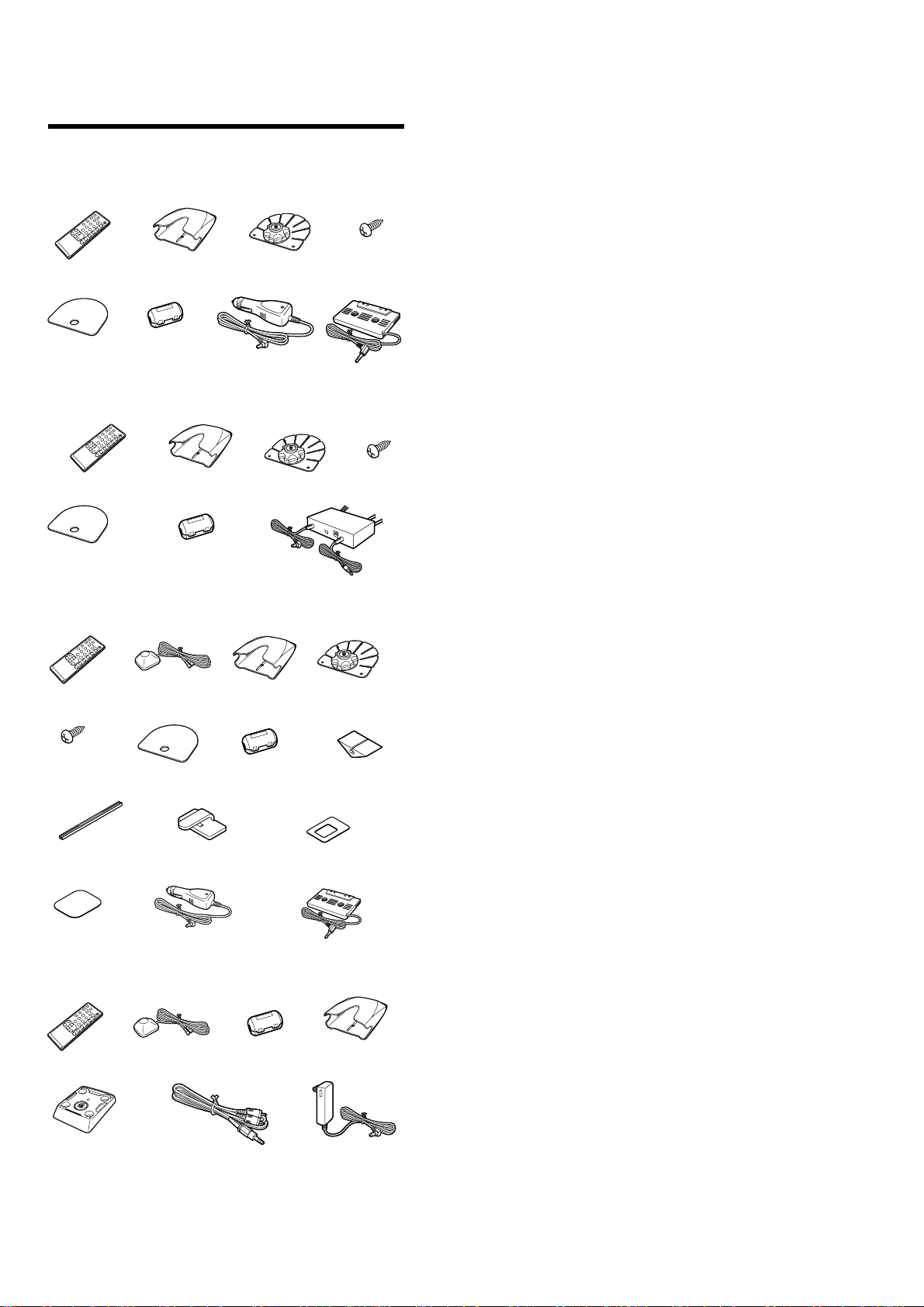
Parts for Installation and Connection
for DRN-XM01C2
Remote
commander (1)
Cover (1)
Car cradle (1)
Ferrite core (2)
for DRN-XM01R2
Remote commander (1)
Cover (1)
Ferrite core (6)
for DRN-XM01CK2
Remote
commander (1)
XM antenna (1)
Car cradle (1)
Car stand (1)
Car battery
cord (1)
Car stand (1)
Car cradle (1)
RF modulator (1)
Screw (5)
Car connecting
pack (1)
Screw (5)
Car stand (1)
1. SERVICING NOTES ······················································· 3
2. GENERAL ·········································································· 5
3. DISASSEMBLY ································································ 7
3-1. Front Panel Assy···························································· 7
3-2. LCD Board ···································································· 7
3-3. Lower Cabinet Assy, Upper Cabinet Assy ····················8
3-4. BB Board, DC Fan (Fan1) ············································· 8
3-5. CPU Board, USB Board ················································ 9
4. TEST MODE ····································································10
5. SERVICE TOOL······························································ 12
5-1. Installing USB Driver ·················································· 12
5-2. Installing DRN-XM01 Service Tool ··························· 19
5-3. How to use DRN-XM01 Service Tool ························ 22
6. DIAGRAMS ······································································ 26
6-1. Circuit Boards Location ·············································· 27
6-2. Block Diagram ···························································· 27
6-3. Printed Wiring Boards – CPU Section – ···················· 29
6-4. Schematic Diagram – CPU Section (1/2) – ················· 30
6-5. Schematic Diagram – CPU Section (2/2) – ················· 31
6-6. Printed Wiring Boards – BB Board – ························· 32
6-7. Schematic Diagram – BB Board (1/3) – ····················· 33
6-8. Schematic Diagram – BB Board (2/3) – ····················· 34
6-9. Schematic Diagram – BB Board (3/3) – ····················· 35
6-10.Printed Wiring Boards – Panel Section – ··················· 36
6-11.Schematic Diagram – Panel Section – ························ 37
6-12.IC Pin Function Description ········································40
Screw (5)
Cable guide (3)
Cover (1)
Cord clamp (4) Cushion with the
Car battery cord (1) Car connecting pack (1)Seal (1)
Ferrite core (2)
for DRN-XM01H2/XM01HK2
Remote
commander (1)
Home stand (1)
XM antenna (1)
Ferrite core (2) Home cradle (1)
Water proof
cushion (1)
double-sided adhesive
tape (1)
AC power adaptor (1)Audio cord (1)
7. EXPLODED VIEWS ······················································ 42
7-1. Front Panel Assy, Lower Panel Assy Section ·············· 42
7-2. Upper Cabinet Assy Section········································ 43
8. ELECTRICAL PARTS LIST ······································· 44
Notes on chip component replacement
•Never reuse a disconnected chip component.
• Notice that the minus side of a tantalum capacitor may be
damaged by heat.
Flexible Circuit Board Repairing
•Keep the temperature of soldering iron around 270˚C
during repairing.
• Do not touch the soldering iron on the same conductor of the
circuit Board (within 3 times).
• Be careful not to apply force on the conductor when soldering
or unsoldering.
SAFETY-RELATED COMPONENT WARNING!!
COMPONENTS IDENTIFIED BY MARK 0 OR DOTTED LINE WITH
MARK 0 ON THE SCHEMATIC DIAGRAMS AND IN THE PARTS
LIST ARE CRITICAL TO SAFE OPERATION. REPLACE THESE
COMPONENTS WITH SONY PARTS WHOSE PART NUMBERS
APPEAR AS SHOWN IN THIS MANUAL OR IN SUPPLEMENTS
PUBLISHED BY SONY.
2

DRN-XM01C2/XM01CK2/XM01H2/
SECTION 1
XM01HK2/XM01R2
SERVICING NOTES
What to do when memory or the BB board or the unit is replaced?
The DRN-XM01 Service Tool is simply referred to as “the dedicated software” in this document.
• When IC504 (flash memory) is replaced
Connect the DRN-XM01 to a PC with the USB cable and enter the serial number in the dedicated software. Then
write the newest program in the flash memory.
(Contents of the user setup are automatically cleared.)
• When IC509 (EEPROM) is replaced
Connect the DRN-XM01 to a PC with the USB cable and enter the serial number in the dedicated software. Then
write the newest program in the flash memory.
(Contents of the user setup are automatically cleared.)
• When failed in writing the flash memory
Connect again the DRN-XM01 to the PC with the USB cable and enter the serial number in the dedicated software.
Then write the newest program in the flash memory.
(Contents of the user setup are automatically cleared.)
• When IC102 (STA450) is replaced
Replace IC103 (ST19AF08) at the same time.
Then perform the CAP-binding (see Note 1) using the dedicated equipment (see Note 2).
Write the radio ID that is displayed on the binding computer, into the label.
Connect again the DRN-XM01 to the PC with the USB cable and enter the serial number in the dedicated software.
Then write the newest program in the flash memory.
(Contents of the user setup are automatically cleared.)
Turn on the po wer of the DRN-XM01. Confirm that the radio ID that is displayed on the CH0 matches the number
on the label. Then attach the label to the DRN-XM01.
After that, update the contract with the XM Radio Inc. Ltd., accordingly.
• When IC103 (ST19AF08) is replaced
Perform the CAP-binding using the dedicated equipment.
Confirm that the radio ID that is displayed on the binding computer matches the indication on the label of the DRN-XM01.
Connect the DRN-XM01 to a PC with the USB cable and enter the newest program in the flash memory using the
dedicated software.
(Contents of the user setup are automatically cleared.)
Turn on the po wer of the DRN-XM01. Confirm that the radio ID that is displayed on the CH0 matches the number
on the label.
After that, update the contract with the XM Radio Inc. Ltd., accordingly.
• When the BB board is replaced
Perform the CAP-binding using the dedicated equipment.
Write the radio ID that is displayed on the binding computer, into the label.
Connect the DRN-XM01 to a PC with the USB cable and write the newest program in the flash memory using the
dedicated software.
(Contents of the user setup are automatically cleared.)
Turn on the po wer of the DRN-XM01. Confirm that the radio ID that is displayed on the CH0 matches the number
on the label.
After that, update the contract with the XM Radio Inc. Ltd., accordingly.
• When the CPU board is replaced
Connect the DRN-XM01 to a PC with the USB cable and write the newest program in the flash memory using the
dedicated software.
(Contents of the user setup are automatically cleared.)
• When the DRN-XM01 is replaced
Perform the “activate” work (see Note 3). Update the contract with the XM Radio Inc. Ltd., accordingly.
Note 1 : CAP : IC103 ST19AF08 (Conditional Access Processor)
Note 2 : Dedicated equipment : It means the dedicated pin-jig that connects the BB board to a binding PC that is
used for the CAP-binding i.e., the procedure of writing the radio ID (XM Radio Hardware ID) to support
the pay services.
Note 3 : “activate” work: The procedure of visiting the XM Radio Inc., Ltd., Web site or contacting the XM Radio
Inc., Ltd., over telephone to tell them the credit card number and radio ID (XM Radio Hardware ID) to
enable reception of pay radio.
3
DRN-XM01C2/XM01CK2/XM01H2/
XM01HK2/XM01R2
SERVICE POSITION
• Disassemble and remove A from the cradle.
cradle
three screws
A
• Connect A to the set as shown below.
Then connect XM antenna and power supply.
BB board
lower cabinet assy
front panel assy
LCD board
CN102
CN501
CPU board
CN502
XM antenna
DC IN (6V)
A
upper cabinet assy
CN301
4
SECTION 2
Remote commander
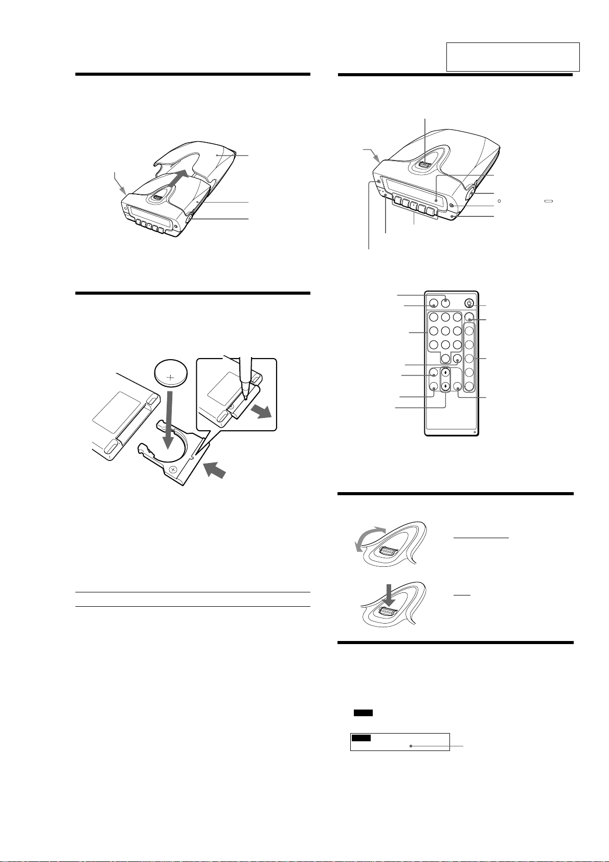
Parts and Identifications
Main unit
Display window
DSPL/BACK/BAND*
2
MEMO
JOG roller (MENU/ENTER)
Preset buttons (1-5)*
1
Cradle release button
Using the JOG Roller (MENU/ENTER)
Turn up or down to select channels,
select the menu items and settings, or
scroll the stored text information in
the menu operation.
Press to display the menu display, or
execute the items or settings in the
menu operation.
Displaying the Radio ID
The receiver has its own ID, and an ID number is required when
registering in XM.
1
Press POWER to turn on the main unit.
2
Turn JOG roller (or press X ⁄ x on the remote) to select
“
XM1
CH0 RADIO ID”.
The radio ID appears.
CHO RADIO ID
XXXXXXXX
XM1
Note
The Radio ID can be displayed only in Channel Scroll mode. See “Playing
the Receiver”.
1 2 3
BAND
MEMO DSPL
4 5 6 1
7 8 9 2
0
SELECT
3
MENU
4
BACK
ENTER
5
CH
PRESET
POWER
Remote sensor
Cradle
release
button
DSPL
POWER*
1
MEMO
Numeric
buttons
SELECT
MENU
BACK
X/x
POWER
BAND*
2
PRESET
ENTER
Radio ID
*
1
The POWER and preset button No. 3 on the main unit have a tactile dot.
*
2
To show the display for selecting a band, hold down DSPL/BACK/
BAND for more than 2 seconds, or press BAND on the remote.
To select a band, press DSPL/BACK/BAND (or BAND on the remote).
Installing the Main Unit in the
Cradle
Insert the main unit completely into the cradle until the main unit is
locked in the cradle.
GENERAL
DRN-XM01C2/XM01CK2/XM01H2/
XM01HK2/XM01R2
This section is extracted from
instruction manual.
button
Cradle release
To remove the main unit from the cradle
While pressing the two cradle release buttons on the left and right sides of
the main unit, pull out the main unit from the cradle.
Replacing the Lithium Battery
into the Remote Commander
Replace the battery when the buttons on the remote commander do not
work. Remove the old battery and insert a new one.
2
Cradle
Main unit
Cradle release
button
1
3
1 Insert a long and thin object into the hole, then pull out the
lithium battery holder.
2 Replace the lithium battery with the positive (+) side facing
up.
3 Insert the battery holder into the remote commander until it
clicks.
Battery life (Approx.)
Sony lithium battery CR2025 1 year
5
DRN-XM01C2/XM01CK2/XM01H2/
XM01HK2/XM01R2
Adjusting the Time Difference
This unit displays the current time by correcting the time difference
between the local time and UTC (coordinated universal time) data being
transmitted. Set the “hour” of your local time in the menu display. The
factory-set is the eastern standard time.
If the current UTC data is not received, “– – : – –” appears in the display.
1
Press POWER to turn on the main unit.
2
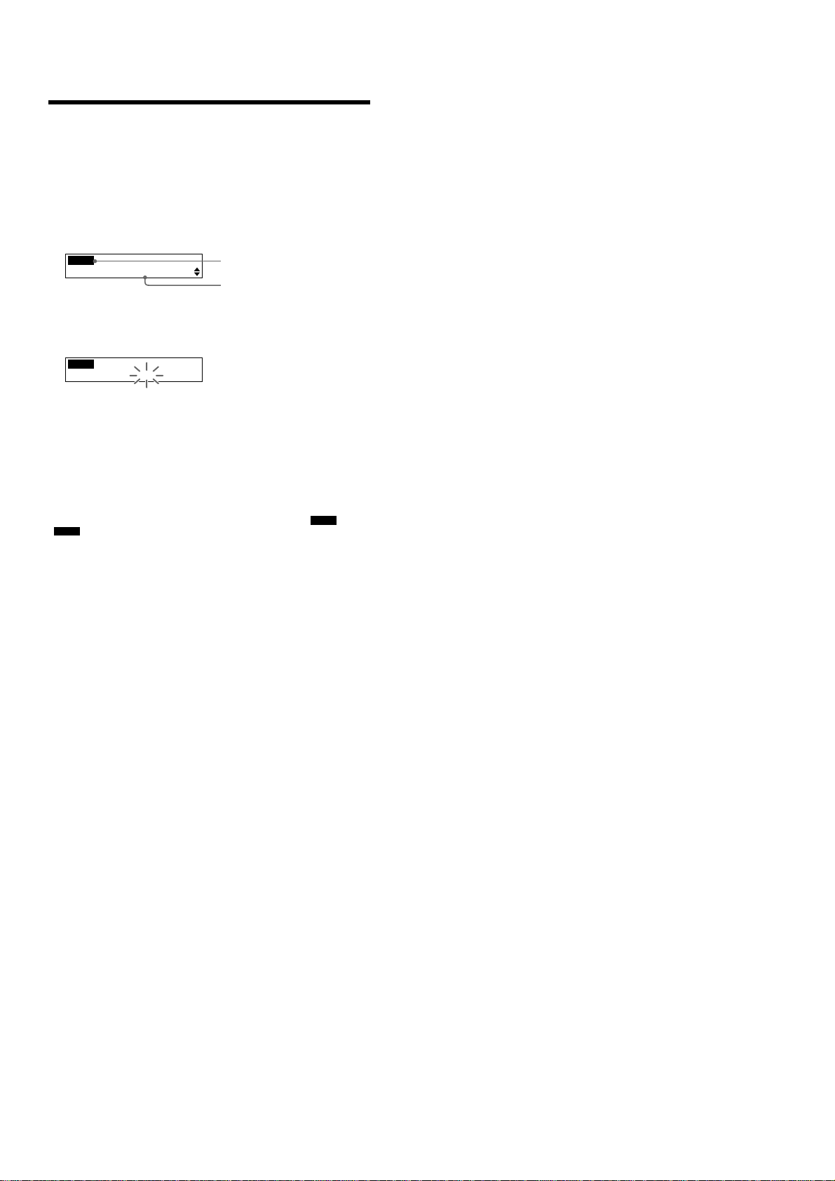
Press JOG roller (or MENU on the remote) to show the
menu display.
The first menu item appears.
MENU
SCROLL MODE
3
Turn JOG roller (or press X ⁄ x on the remote) to select
“TIME ADJUST” and press JOG roller (or ENTER on the
remote).
The “hour” flashes.
MENU
TIME ADJUST
11:12AM
12:00 AM = midnight
12:00 PM = noon
4
Turn JOG roller (or press X ⁄ x on the remote) to adjust the
hour and press JOG roller (or ENTER on the remote).
The display returns to the tuned channel display.
Note
This unit does not have the Daylight Saving Time (summer time)
function.
To check the current time while listening to a broadcast
Press DSPL/BACK/BAND (or DSPL on the remote) until the “
“
” display appears. See “Checking the Tuned Channel
TIME
Information”.
To cancel a selection
Press DSPL/BACK/BAND (or BACK on the remote) to return to the
previous display during menu operation.
Press MENU on the remote commander to exit the menu display. The
display returns to the tuned channel display.
Menu icon
Menu item
INFO
” and
6
r
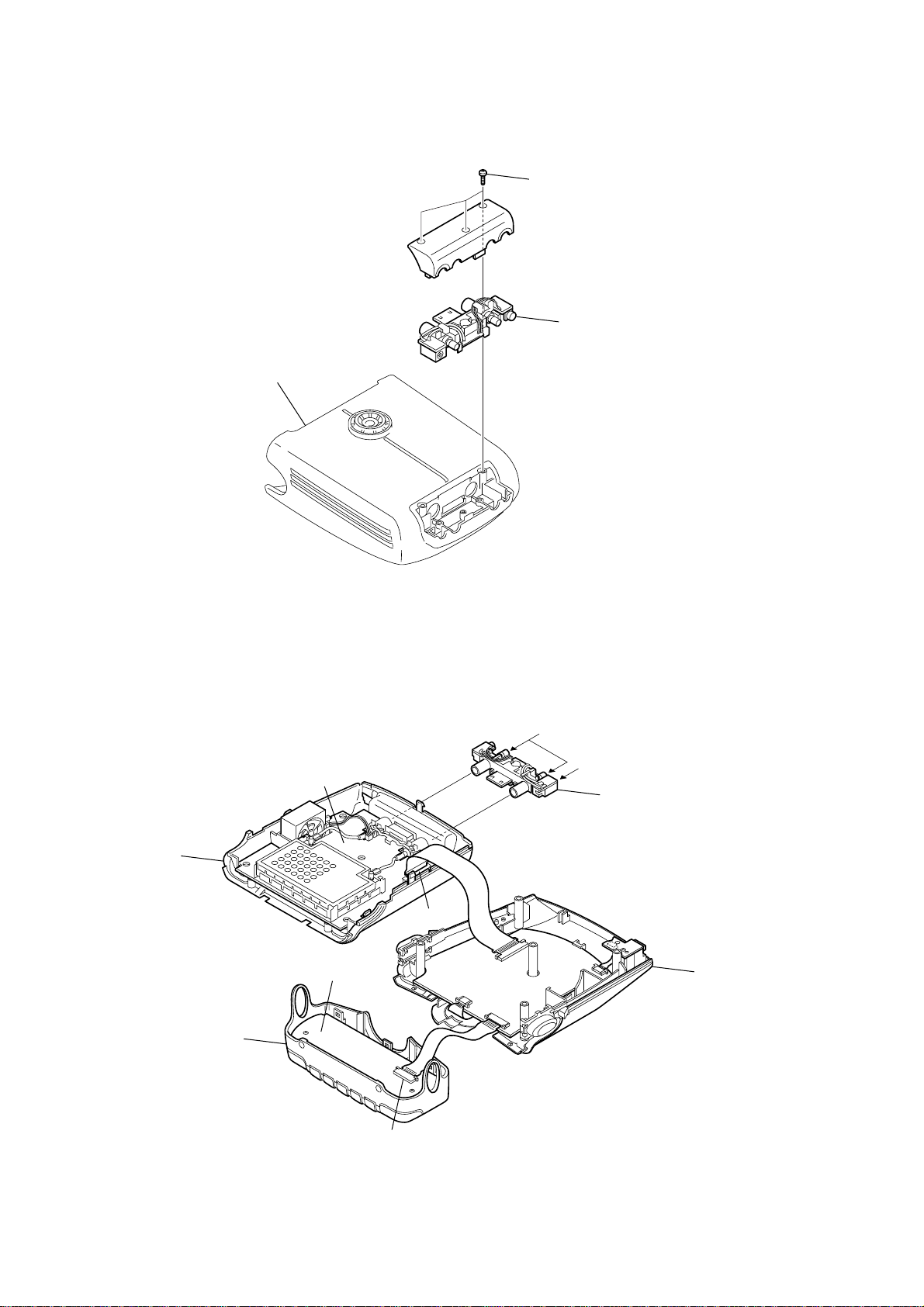
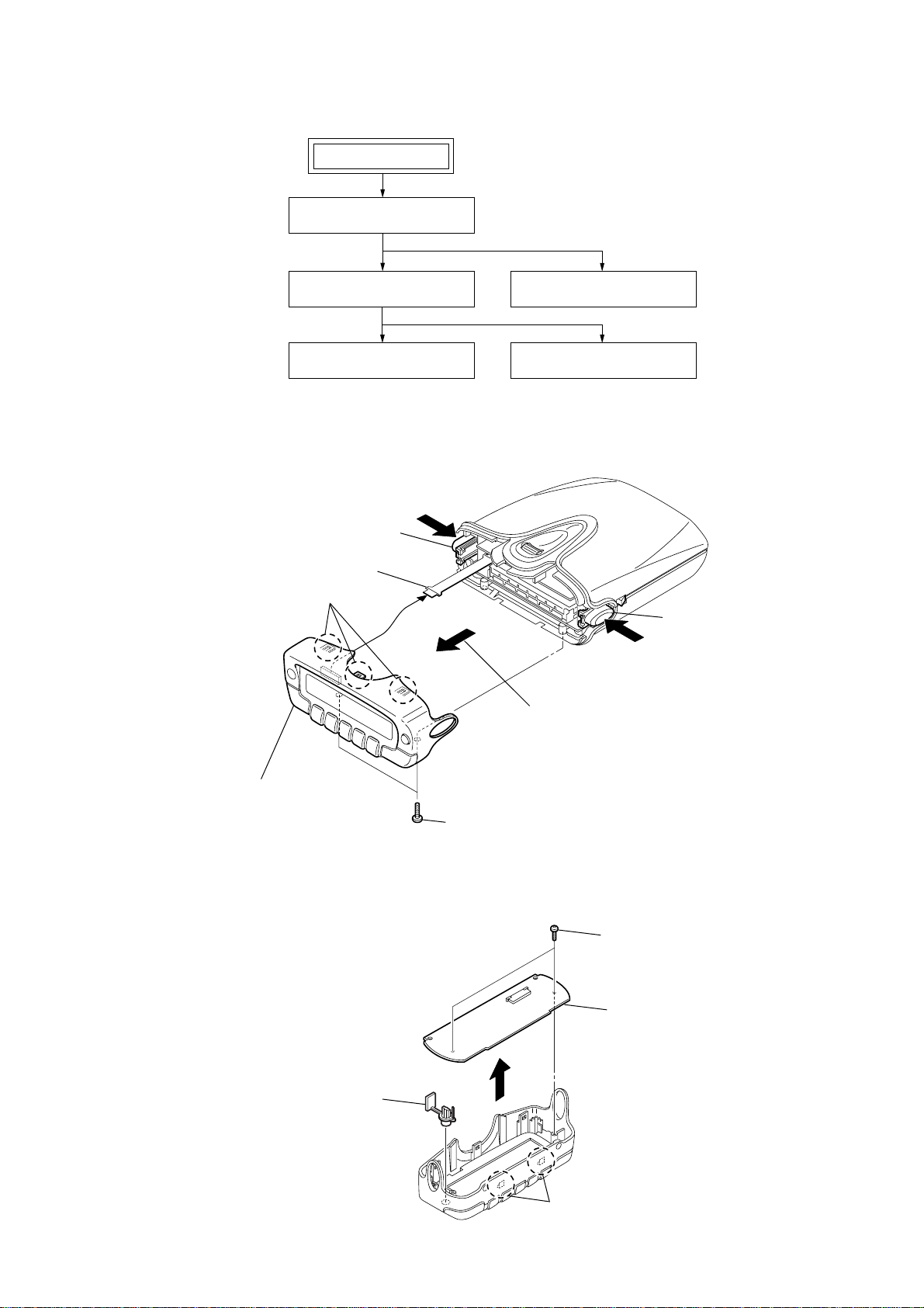
Disassemble the unit in the order as shown below.
FRONT PANEL ASSY
SET
SECTION 3
DISASSEMBLY
DRN-XM01C2/XM01CK2/XM01H2/
XM01HK2/XM01R2
LOWER CABINET ASSY,
UPPER CABINET ASSY
BB BOARD, DC FAN (FAN1)
Note : Follow the disassembly procedure in the numerical order given.
3-1. Front Panel Assy
A
button (release L)
4
flexible board
(20P) (CN301)
2
three claws
C
5
front panel assy
LCD BOARD
CPU BOARD, USB BOARD
button (release R)
B
While pushing the button (release L)
3
and the button (release R) in the
direction of the arrow A and B,
remove the front panel assy in the
direction of the arrow C.
3-2. LCD Board
4
button (dspl)
1
two screws (M1.7)
2
two claws
1
two screws
(M1.7
3
LCD board
×
6)
7
DRN-XM01C2/XM01CK2/XM01H2/
y
)
XM01HK2/XM01R2
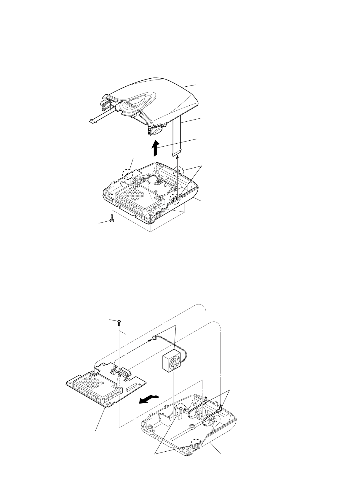
3-3. Lower Cabinet Assy, Upper Cabinet Assy
2
claw
5
upper cabinet assy
3
flexible board
(30P) (CN102 )
Remove the upper cabinet ass
in the direction of the arrow.
2
two claws
1
five screws
(+BTP 2.6 × 10)
3-4. BB Board, DC Fan (Fan1)
3
two screws
(M1.7
4
lower cabinet assy
1
×
6)
(CN104)
dc fan
(FAN1)
2
two cables
(with connector
5
Remove the BB board
in the direction of the arrow.
4
two claws
cabinet (lower) assy
8
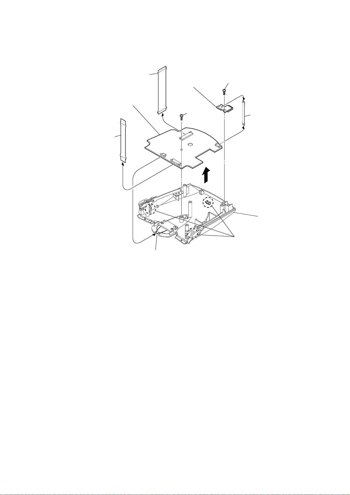
3-5. CPU Board, USB Board
)
1
(30P) (CN501)
9
Remove the CPU board in
the direction of the arrow.
flexible board
6
USB board
7
(M1.7
screw
DRN-XM01C2/XM01CK2/XM01H2/
XM01HK2/XM01R2
4
screw
×
(M1.7
×
6)
6)
(CN2)
5
flexible board (USB
2
flexible board
(20P) (CN502 )
3
flexible board
(JOG) (CN503)
(CN504)
8
three claws
cabinet (upper)
9
DRN-XM01C2/XM01CK2/XM01H2/
XM01HK2/XM01R2
SECTION 4
TEST MODE
4-1. TEST MODE
4-1-1. SETTING THE TEST MODE
The following is the method of entering the test mode under the
condition of power-off.
Procedure:
1. Press the JOG roller and the preset button 2 simultaneously for
three seconds.
2. Press the preset button 1 .
3. Press the preset button 3 .
4. Press the preset button 5 .
5. The menu screen is displayed.
4-1-2. EXITING THE TEST MODE
Press the POWER button e xcluding LCD/KEY/BA CKLIGHT T est
Mode.
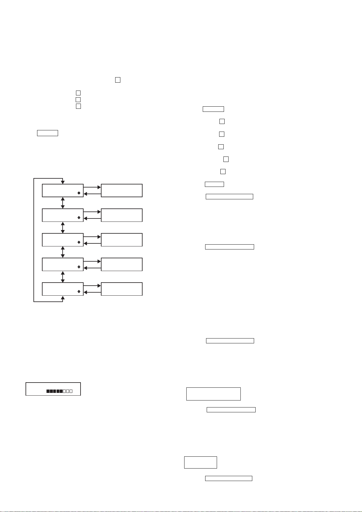
4-1-3. TEST MODE MENU
Select the menu and press the JOG roller.
(MENU) (MODE)
JOG roller
TEST MENU
LCD ADJUST
TEST MENU
LCD/KEY/BKLIGHT
TEST MENU
EEP INIT.
TEST MENU
SOFT VERSION
TEST MENU
SERIAL NO.
JOG PUSH
DSPL/BACK
LCD
Adjustment Mode
LCD/KEY/BACKLIGHT
Check Mode
EEPROM
Initialization Mode
SOFT VERSION
Display Mode
SERIAL NO.
Display Mode
4-1-4. OPERATION OF THE TEST MODE
[LCD Adjustment Mode]
* This mode is used to adjust the contrast of LCD to the medium
value.
This adjustment is different from user's adjustment of the contrast
in 8 levels.
Procedure:
1. Select the MENU LCD ADJUST and press the JOG roller.
2. The following screen is displayed.
LCD ADJUST XX
L H
XX : LCD Contrast Value (00 to 31)
4-1-5. OPERATION OF THE TEST MODE
[LCD/KEY/BACKLIGHT Check Mode]
* This mode is used to check the operation of LCD, Keys, the JOG
roller, the backlight and the power LED.
Procedure:
1. Select the MENU LCD/KEY/BKLIGHT and press the JOG roller .
The test is excuted by pressing buttons correctly in the following
order.
2. All segments of LCD and the power LED are turnd on and the
backlight is lit brightly.
3. Press the POWER b utton. segments of LCD changes to checkers
and the backlight keeps bright.
4. Press the preset 1 button. LCD displays reverse checkers and
the backlight is bright.
5. Press the preset 2 button. LCD displays lateral stripes and the
backlight is bright.
6. Press the preset 3 button. LCD displays vertical stripes and the
backlight is bright.
7. Press the preset 4 button. LCD displays chekers and the
backlight is dim.
8. Press the preset 5 button. LCD displays reverse chekers and
the backlight is dim.
9. Press the MEMO button. LCD displays lateral stripes and the
backlight is dim.
10. Press the DSPL/BACK/BAND button. LCD displays vertical
stripes and the backlight is dim.
Rotate the JOG roller down. The message “JOG TEST COUNT : :
11.
00” is displayed. Rotate the JOG roller down to “COUNT : : 08”.
12. Rotate the JOG roller up. The v alue “JOG TEST COUNT : : 08”
decreases to “COUNT : : 00”.
13.Press the JOG roller. LCD, the backlight and the power LED
are turned out.
14.Press the DSPL/BACK/BAND button to return to the TEST
MENU.
[EEPROM Initialization Mode]
* This mode is used to initialize the values of EEPROM without
LCD factory adjustment value and the serial number.
Note: When this mode is activated, all of the information that has
been preset by customer is cleared. Before activating this mode,
take a note of the information that has been preset by customer.
After Test mode is completed, set the saved information to
recover the original setup.
Procedure:
1. Select the MENU EEP INIT. and press the JOG roller. Then
initialization is executed.
2. The message “EEP INT. COMPLETE” is displayed.
3. Press the DSPL/BACK/BAND button to return to the TEST
MENU.
[SOFT VERSION Display Mode]
Procedure:
1. Select the MENU SOFT VERSION and press the JOG roller.
2. The following message is displayed,
SOFT VERSION R : ROM
R : XX.XX F : XX.XX F : Flash
3. Adjust the LCD to the center contrast in 32 levels by rotating
the JOG roller up or down.
4. Press the JOG roller to set the value.
5. The display returns to the TEST MENU.
10
3. Press the DSPL/BACK/BAND button to return to the TEST
MENU.
[SERIAL NO. Display Mode]
Procedure:
1. Select the MENU SERIAL NO. and press the JOG roller.
2. The following message is displayed.
SERIAL NO.
XXXXXX XXXXXX : Serial No. (6 digits)
3. Press the DSPL/BACKBAND button to return to the TEST
MENU.
DRN-XM01C2/XM01CK2/XM01H2/
XM01HK2/XM01R2
4-2. DIAGNOSTIC MODE
4-2-1. SETTING THE DIAGNOSTIC MODE
Press the JOG roller and the preset button 5 simultaneously for
three seconds under the condition of power-off.
Press the JOG roller when the set is powered on.
4-2-2. EXITING THE DIAGNOSTIC MODE
Press the POWER button to exit from this mode.
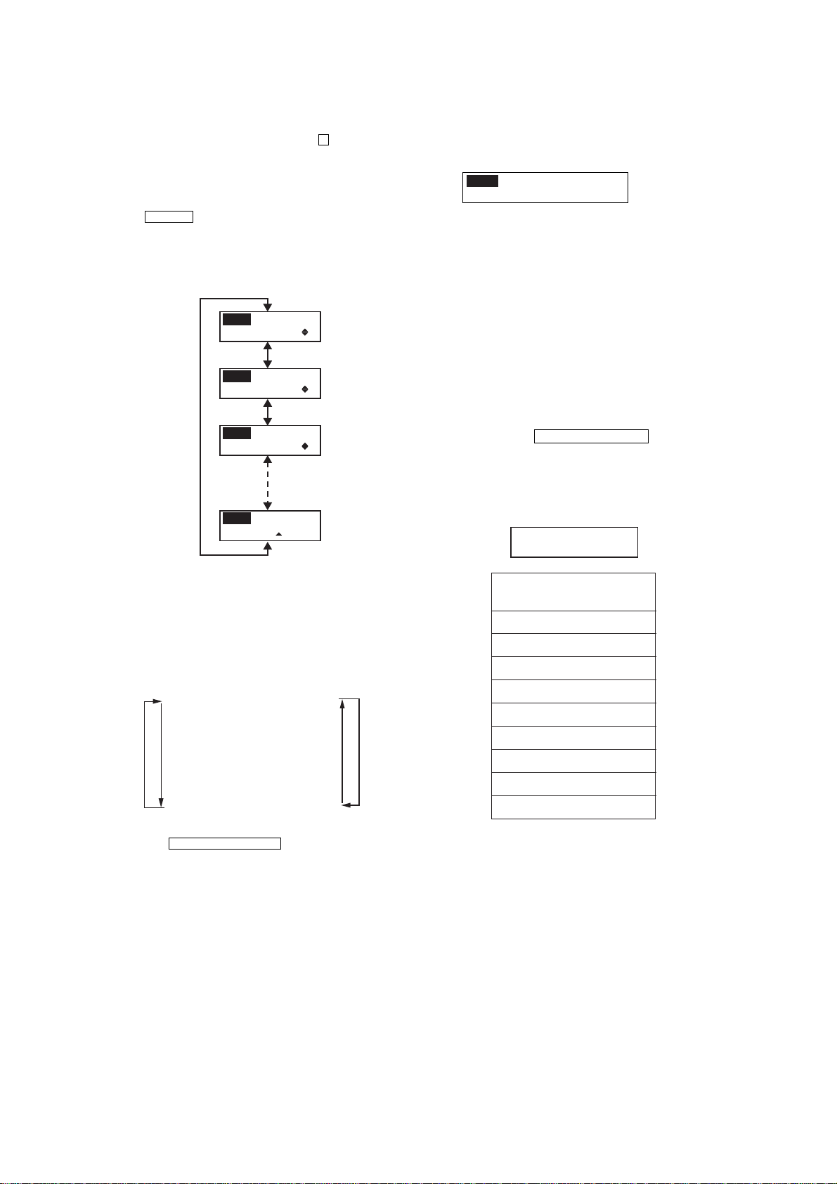
4-2-3. MENU
Select the menu and press the JOG roller.
JOG roller
MENU
DIAG. MODE
MENU
BER
MENU
SCROLL MODE
MENU
RECEPTION STATUS
[BER Display Mode]
Procedure:
1. Select the MENU BER and press the JOG roller.
2. The following message is displayed.
MENU
XXX1 XXX2 XXX3 E
XXX4 XXX5 X6 X7
XXX1 : SAT1 BER
(4 digits Hex data)
XXX2 : SAT2 BER
(4 digits Hex data)
XXX3 : TERR BER
(4 digits Hex data)
XXX4 : RS Error Byte
(4 digits Hex data)
XXX5 : RS Error Block
(4 digits Hex data)
X6 : SAT A GC
(2 digits Hex data)
X7 : TER AGC
(2 digits Hex data)
E : Ensemble
(A, B or space)
3. Press the DSPL/BACK/BAND button to return the DIAG.
MENU.
4-3. SYSTEM ERROR LIST
If system error is happened, the message of system error is displayed
and the set sounds beep.
SYSTEM ERROR xx
XXXXXXXXXXXXXXXXXXXX
xx : Error information per bit
4-2-4. OPERATION
[Diagnostic Mode]
Procedure:
1. Select the MENU DIAG. MODE and press the JOG roller.
2. The message “STATE1 QOS Test” is displayed.
3. Select the message(menu) by rotating the JOG roller up or down
as following order.
STATE1 QOS Test
STATE2 Terr Err
STATE3 Sat1 Err
STATE4 Sat2 Err
STATE5 Tuner Stat
STATE6 Audio Err
STATE7 Gen Err
STATE8 Ext Err0
STATE9 Ext Err1
4. Press the DSPL/BACK/BAND button to return the DIAG.
MENU.
UpDown
INFORMATION OF ERROR
(XXXXXXXXXXXXXXXXXXXX)
TUNER UNLOCKED
DSP NO RESPOND
DSP INCORRECT RESP.
UNSUPPORTED DSPSW
CDEC NO RESPOND
I2C BUS ERROR
CAP ERROR
EEPROM ERROR
EEPROM FORMAT ERROR
11
DRN-XM01C2/XM01CK2/XM01H2/
XM01HK2/XM01R2
SECTION 5
SERVICE TOOL
5-1. Installing USB Driver
This section describes how to install USB driver for DRN-XM01.
Operating environment
Operating environments of a PC to which the driver software is installed are as follows.
* Applicable OSs are Windows98SE, Windows 2000 and Windows ME.
* USB can be connected.
Installation
For Windows 98SE
1. Insert the driver software program CD into the PC.
2. Connect the PC and DRN-XM01 with USB cable.
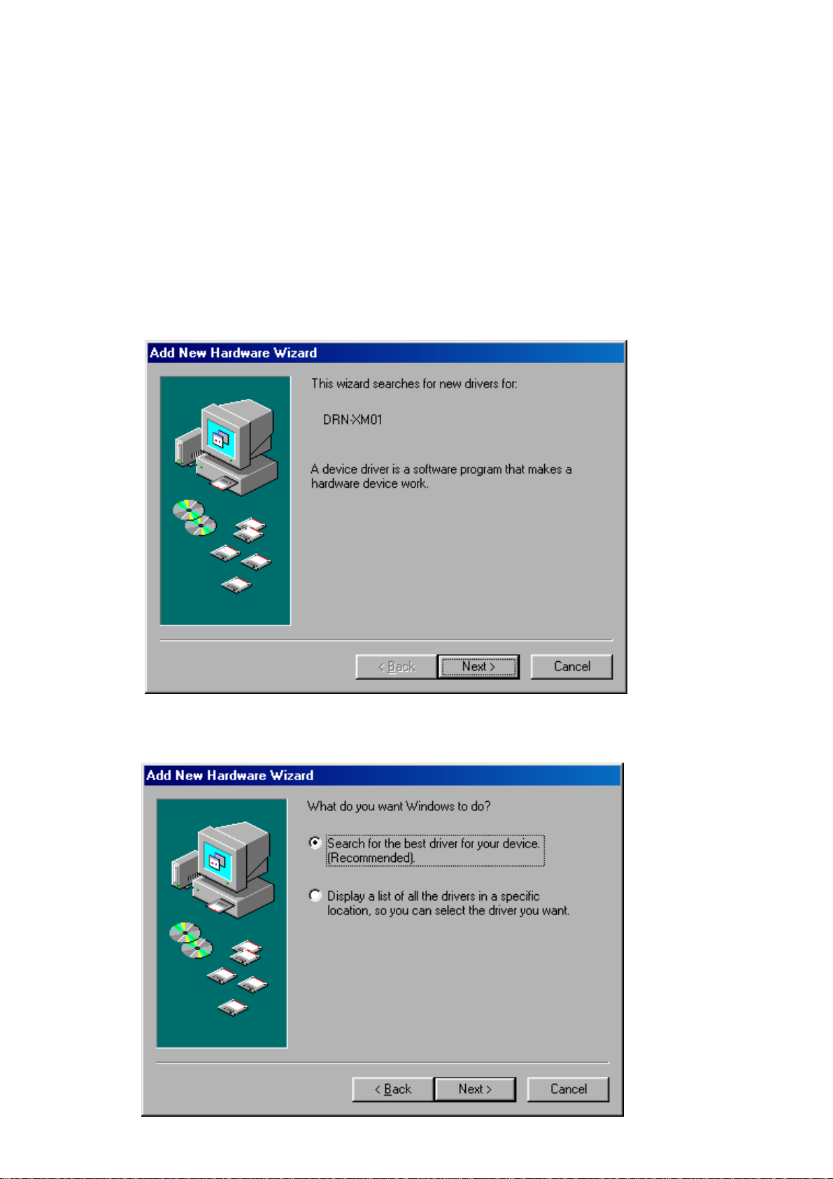
3. After a while, the following dialog box appears. Press the Next button.
4. Then the following dialog box appears. Select ”Search for the best driver for your device (Recommended).” and press the NEXT button.
12
DRN-XM01C2/XM01CK2/XM01H2/
XM01HK2/XM01R2
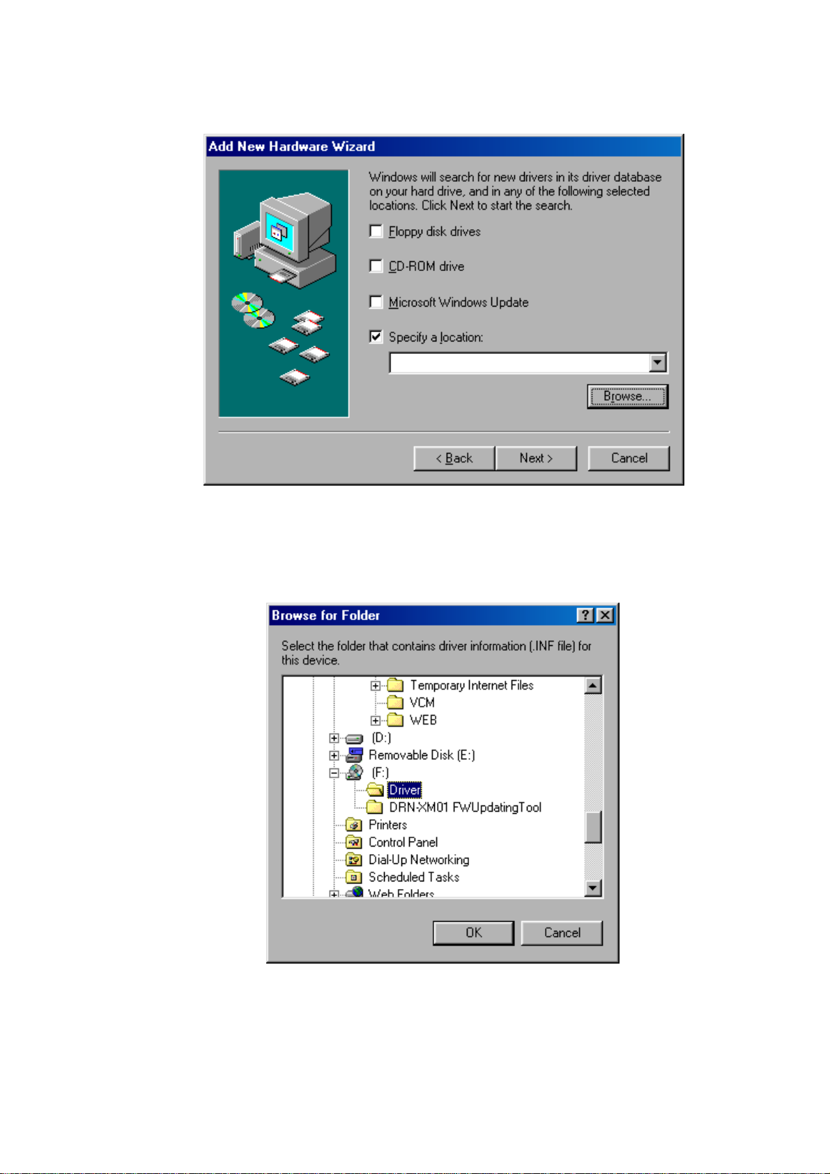
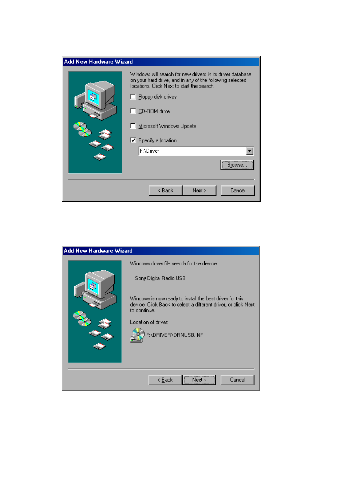
5. Then the following dialog box appears. Click on the check box ”Specify a location:” and press the Browse…button.
6. The following file selector dialog box appears. Select ”(CD dri ve):\Dri ver”(CD dri ve is F in this sample picture) and press the OK button.
13
DRN-XM01C2/XM01CK2/XM01H2/
XM01HK2/XM01R2
7. Confirm the path and press the NEXT button.
8. After a while, the following dialog box appears. Press the NEXT button.
14
DRN-XM01C2/XM01CK2/XM01H2/
XM01HK2/XM01R2
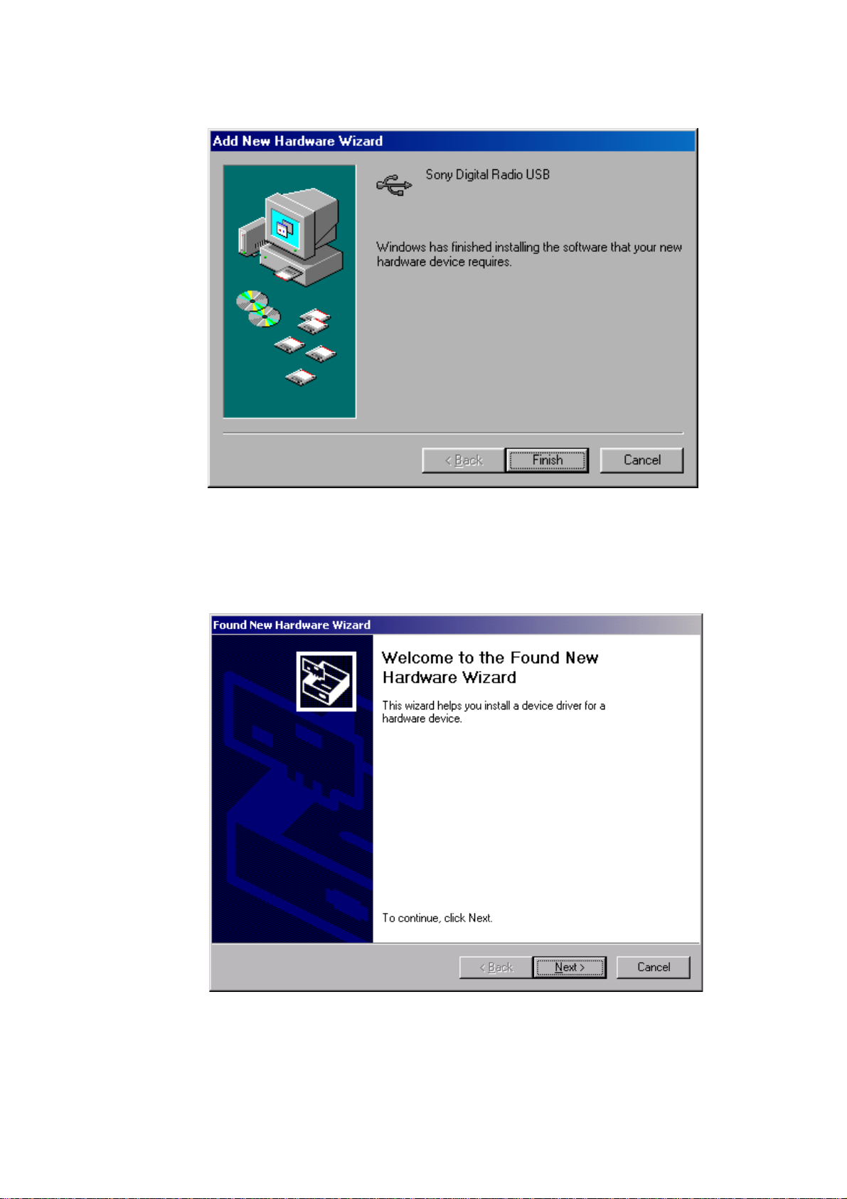
9. After a while, installation is completed and the following dialog box appears. Press the Finish button to terminate the insta llation program.
For Windows 2000
1. Insert the driver software program CD into the PC.
2. Connect the PC and DRN-XM01 with USB cable.
3. After a while, the following dialog box appears. Press the NEXT button.
15
DRN-XM01C2/XM01CK2/XM01H2/
XM01HK2/XM01R2
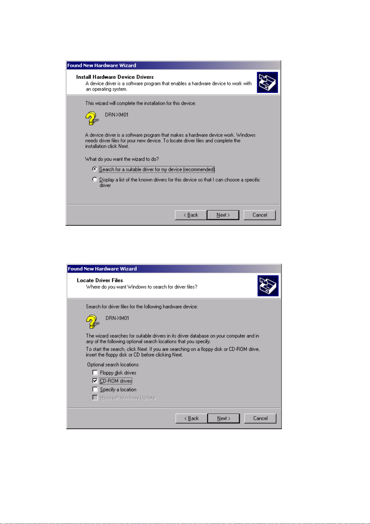
4. Then the following dialog box appears. Select ”Search for suitable driver for my device(recommended)” and press the NEXT button.
5. Then the following dialog box appears. Select ”CD-ROM drives” and press the NEXT button.
16
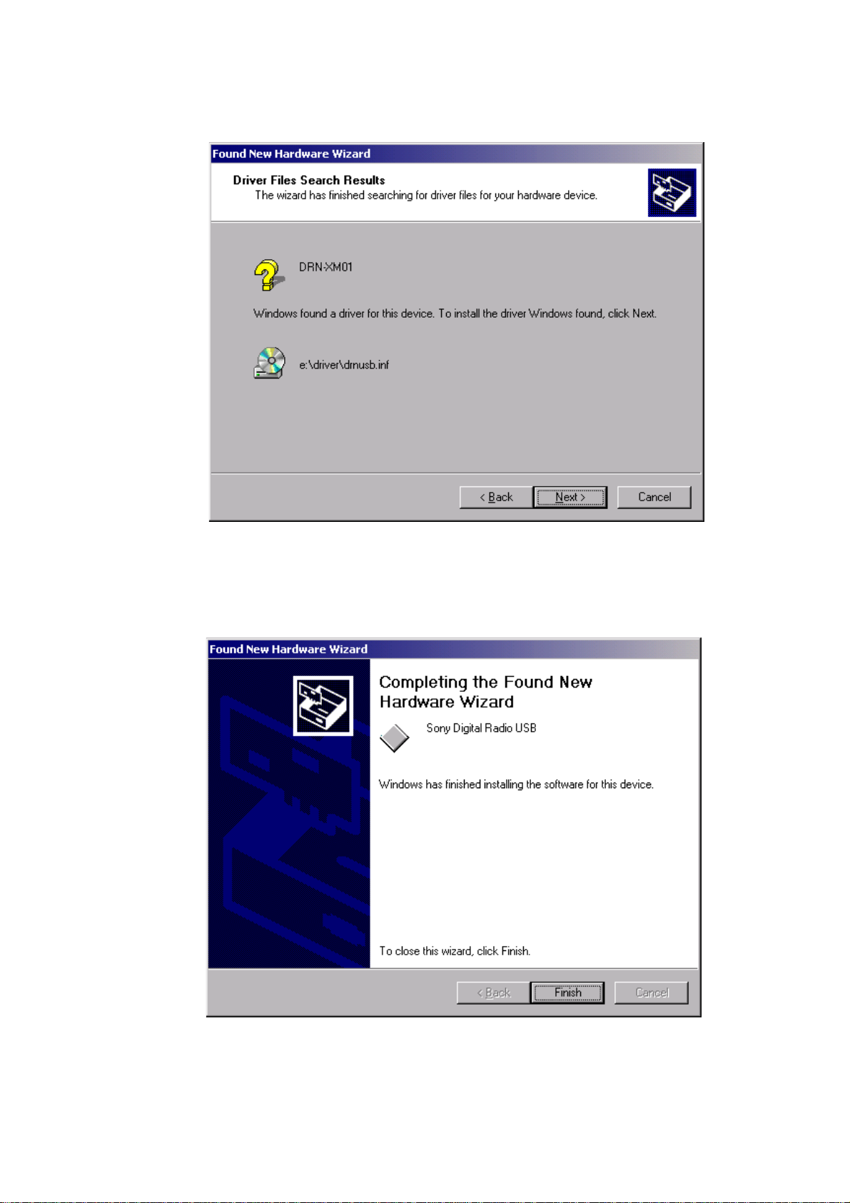
6. After a while, the following dialog box appears. Press the Next button.
DRN-XM01C2/XM01CK2/XM01H2/
XM01HK2/XM01R2
7. After a while, installation is completed and the following dialog box appears. Press the Finish button to terminate the insta llation program.
17
 Loading...