


DIGITAL VIDEOCASSETTE RECORDER
DNW-A25WS
DNW-A25WSP
INSTALLATION MANUAL
1st Edition
Serial No. 15001 and Higher: DNW-A25WS
Serial No. 45001 and Higher: DNW-A25WSP

! W ARNING
This manual is intended for qualified service personnel only.
To reduce the risk of electric shock, fire or injury, do not perform any servicing other than that
contained in the operating instructions unless you are qualified to do so. Refer all servicing to
qualified service personnel.
! WARNUNG
Die Anleitung ist nur für qualifiziertes Fachpersonal bestimmt.
Alle Wartungsarbeiten dürfen nur von qualifiziertem Fachpersonal ausgeführt werden. Um die
Gefahr eines elektrischen Schlages, Feuergefahr und Ver letzungen zu vermeiden, sind bei
Wartungsarbeiten strikt die Angaben in der Anleitung zu befolgen. Andere als die angegeben
Wartungsarbeiten dürfen nur von Personen ausgeführt werden, die eine spezielle Befähigung
dazu besitzen.
! AVERTISSEMENT
Ce manual est destiné uniquement aux personnes compétentes en charge de l’entretien. Afin
de réduire les risques de décharge électrique, d’incendie ou de blessure n’effectuer que les
réparations indiquées dans le mode d’emploi à moins d’être qualifié pour en effectuer d’autres.
Pour toute réparation faire appel à une personne compétente uniquement.
DNW-A25WS/A25WSP

Table of Contents
Manual Structure
Purpose of this manual .............................................................................................. 2
Related manuals......................................................................................................... 2
1. Installation
1-1. Installation Procedure..................................................................................1-1
1-2. Supplied Accessories ..................................................................................1-1
1-3. Operating Conditions ..................................................................................1-1
1-4. Power Supply ..............................................................................................1-2
1-5. Installation Space ........................................................................................1-3
1-6. Connectors/Cables.......................................................................................1-4
1-7. Signal Inputs and Outputs ...........................................................................1-5
1-8. Settings for Internal Switches/Slit Lands.................................................... 1-8
1-8-1. AU-249 Board ............................................................................1-8
1-8-2. RE-150 Board.............................................................................1-9
1-9. Setup Extended Menu ...............................................................................1-10
1-10. Settings for External Editors .....................................................................1-11
1-10-1. Time Code Settings for Recorder.............................................1-11
1-10-2. VTR Constant Settings for External Editors ............................1-11
1-10-3. System Phase Adjustment ........................................................1-11
1-10-4. Setup Menu Setting of ITEM-701............................................1-11
1-11. Removing/Reattaching the Plug-in Boards............................................... 1-12
1-12. How to Take Out the Cassette Whose Tape is Slacked ............................ 1-14
DNW-A25WS/A25WSP
Appendix A Setting Check Sheet
1

Purpose of this manual
Related manuals
Manual Structure
This manual is the installation manual of digital videocassette recorder
DNW-A25WS/A25WSP.
This manual is intended for use by trained system and service engineers, and
provides the information that is required to install (environment, connection information, initial setting, etc.) .
Besides this “installation manual”, the following manuals are available for digital
videocassette recorder DNW-A25WS/A25WSP.
..
. Operation Manual (Supplied with the unit.)
..
This manual is necessary for application and operation (and installation) of the unit.
..
. Maintenance Manual (available on request)
..
Volume-1 : Service Instruction
Volume-2 : Parts List, Diagrams
These manuals describe the maintenace and service information (service overview, adjustments, board layouts, schematic diagrams, detailed parts list, etc.) for
this unit. If these manuals are required, please contact your local Sony Sales
Office/Service Center.
..
. Protocol Manual of Remote (9-pin) Connector (available on request)
..
This manual explains the protocol for controlling the VTR via the RS-422A (9-pin
serial remote). If this manual is required, please contact your local Sony Sales
Office/Service Center.
..
. BKNW-225 Maintenance Manual (Supplied with the BKNW-225)
..
This manual describes the spare parts list and the exploded view for the service
parts of the docking kit BKNW-225, that is used when the two DNWs are coupled.
2
DNW-A25WS/A25WSP
Section 1
Installation
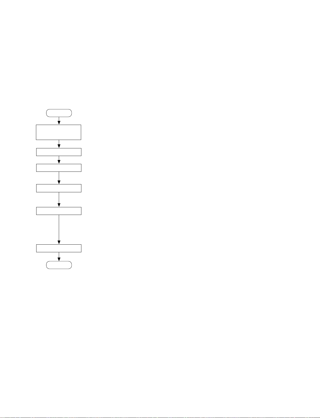
1-1. Installation Procedure
Installation procedure of this unit is shown on the following flowchart.
Refer to each section about detail of each flow.
The operation manual is also reqruired to do *-marked
flow.
Start
Determination of
installation place
Unpacking
Installation
*Connection
1-3. Operating Conditions
1-4. Power Supply
1-5. Installation Space
1-6. Connectors/Cables
1-7. Signal Inputs and Outputs
1-3. Operating Conditions
c
Do not block an air vent. If ventilation is not enough, the
unit may be damaged due to increase the internal temperature of the unit.
. Do not shove the unit into cramped place with poor
ventilation.
. Be sure to make cleaning if a cooling fan is covered with
dust.
. Replace a cooling fan periodically.
. Do not place the unit on a longhaired carpet.
. Do not cover the unit with cloth.
n
Good air circulaiton is essential to prevent internal heat
build-up. Place the unit in location with sufficient air
circulation.
Do not block the ventilation holes of the cabinet and the
front and rear panels.
*Initial setup
*Operation check
End
1-8. Settings for Internal
Switches/Slit Lands
1-9. Setup Extended Menu
1-10. Settings for External Editors
1-2. Supplied Accessories
Cap, BNC ........................................................................ 11
Cap, DC OUT ....................................................................2
Cap, XLR (F)..................................................................... 2
Cap, XLR (M) ................................................................... 5
Cap, DUST ........................................................................ 1
Shoulder belt assembly...................................................... 1
Rear panel cover ................................................................ 1
Operation manual .............................................................. 1
Installation manual ............................................................ 1
Operating temperature: 0dC to 40dC
Operating humidity: 25% to 80% (Condensation not
allowed)
Storage temperature: _20dC to 60dC
Locations to avoid:
. Areas where the unit will be exposed to direct sunlight
of any other strong lights.
. Areas near heat sources.
. Dusty areas or areas subject to vibration.
. Areas with strong magnetic field.
. Areas with much electrical noise.
. Areas with much static electricity.
. Areas that is impossible to find a specified room for
installation.
(Refer to Section “1-5. Installation Space” .)
. Areas windtight.
n
After installation, be sure to use the supplied caps for
protecting unused connectors.
DNW-A25WS/A25WSP
1-1
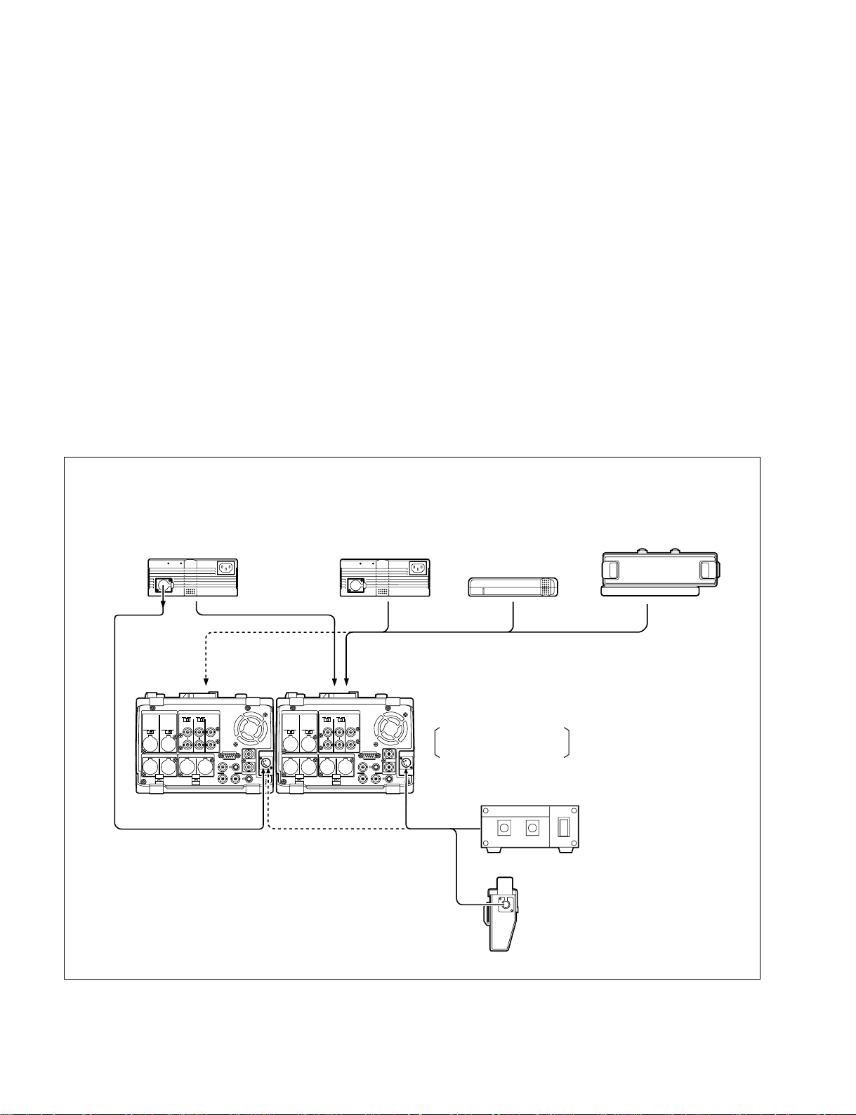
1-4. Power Supply
1-4. Power Supply
The unit works either on AC current (using the AC adaptor) or battery. When repairing or checking the
unit, however, AC-operation is recommended.
Power Voltage: DC 11 to 17 V
Power Consumption : 65 W
m
. The AC adaptor AC-DN1 cannot be used to derive power.
. The AC adaptor AC-DN2A/DN2B can supply power to two VTRs simultaneously. The AC-DN2 with
serial No.11001 or higher can supply, too. If the above adaptor is used, power on the VTRs and load
cassettes in turn allowing for an inrush current.
. While the unit is battery-operated, the remaining battery capacity is displayed on the sub menu indica-
tor. When the battery is nearly dead, the WARNING indicator on the side of the LCD monitor will
blink. For details, refer to the operation manual supplied with the unit.
Connection example (when operating two VTRs)
AC adaptor
AC-DN2A/DN2B
DC OUT
(DC cable)
DC IN
AC adaptor
AC-DN2A/DN2B
Battery terminal
Lithium-ion battery
BP-L90A/L60A
DNW-A25WS/A25WSP
Rear View
Ni-cd battery
BP-90A
+
Battery adaptor
DC-L90
AC adaptor
AC-550
1-2
Ni-cd battery
BP-90A
+
Battery adaptor
DC-210
DNW-A25WS/A25WSP
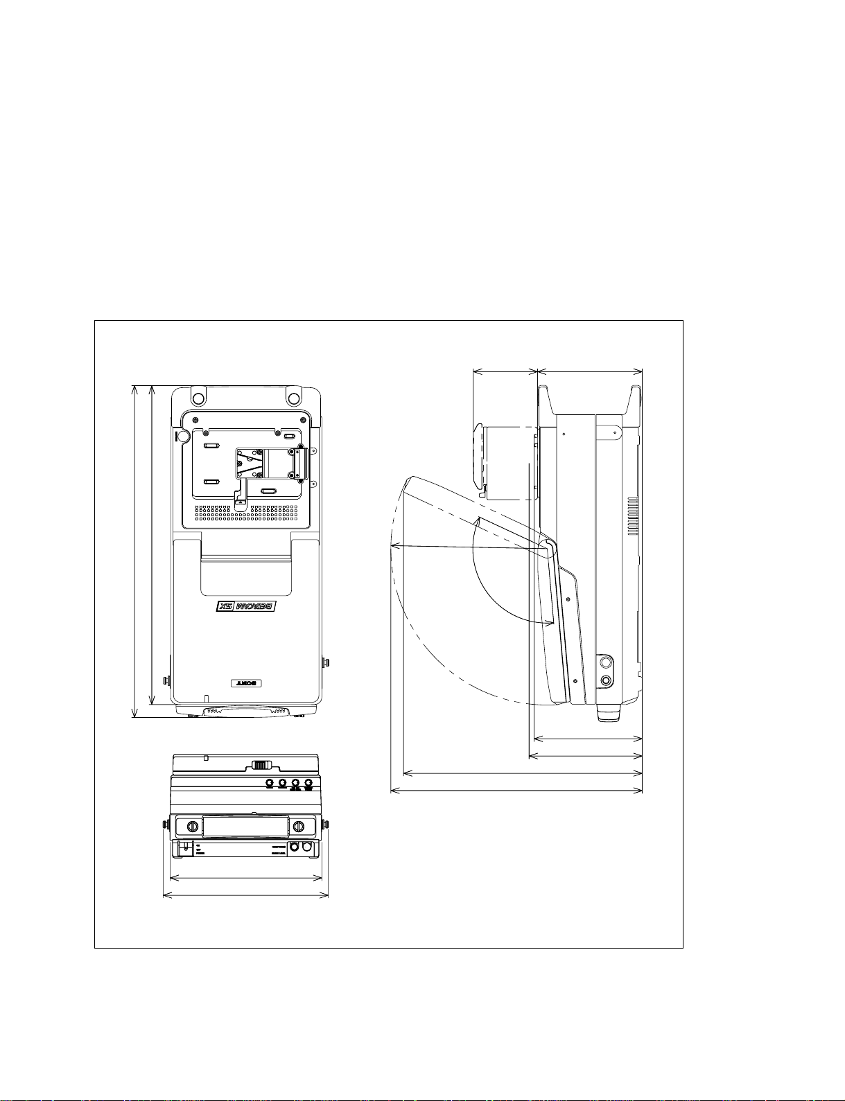
1-5. Installation Space
c
To avoid an injury, do not install the unit on rickety table.
Ventilation and Installation Space for Servicing
. Do not block an exhaust section and an air vent (rear panel).
. In order to make a unit with good ventilation, ensure sufficient clearance around the unit.
. In order to ensure a workspace, more than 20 cm behind the unit is required.
Outside Dimensions
1-5. Installation Space
461
443
R217
120d
89
145
150
157
331
349
DNW-A25WS/A25WSP
210
230
Unit : mm
1-3

1-6. Connectors/Cables
1-6. Connectors/Cables
Connection made with the connector panels during installation or service, should be made with the
connectors or complete cable assemblies specified in the following list, or equivalent parts.
Panel indication Connection connector (Sony P/N) Connection cable (Sony P/N)
VIDEO REF IN Plug, BNC (1-564-742-11) RG-59B/U cable
VIDEO INPUT
VIDEO OUTPUT
TC IN
TC OUT
SDI IN Plug, BNC (1-564-742-11) BNC coaxial cable
SDI OUT (1-791-456-11: supplied with BKNW-225) or
BELDEN 8281 cable (Maximum cable length: 200 m)
AUDIO INPUT XLR 3P, MALE (1-508-084-00) –––––––
AUDIO OUTPUT XLR 3P, FEMALE (1-508-083-00) –––––––
MONITOR OUTPUT
DC IN XLR 4P, FEMALE (1-508-362-00) DC power cord (1-551-577-00:supplied with AC-550/
550CE)
DC OUT Plug 4P MALE (1-566-425-11) –––––––
REMOTE Plug 9P MALE (1-560-651-00) 9P remote control cable
Shell, Junction 9P (1-561-749-00) (1-783-089-12: supplied with BKNW-225) or
RCC-5G(5 m)/10G(10 m)/30G(30 m)
AUX Plug 6P MALE (1-560-078-00) –––––––
HEADPHONES JM-60 stereo phone plug –––––––
(Separately available)
1-4
DNW-A25WS/A25WSP

1-7. Signal Inputs and Outputs
1-7. Signal Inputs and Outputs
+48V
CH-1
AUDIO OUTPUT
1/3
1
ONOFF
+48V
+4dBu_60 0
CH-2
2/4
2 3 4 6 875
75Z
ONOFF
REF.
+4dBu_60 0
IN
MONITOR OUTPUT
R L
9 !/ != ![ !\!]!-
Communications Connectors
VIDEOAUDIO INPUT
ONOFF
OFF
75Z
INPUT OUTPUT
ON
1
2(SUPER)
REMOTE
SDI IN DC OUT
12
TC IN
TC OUTSDI OUT
AUX
DC-IN
< Connector panel >
6 REMOTE D-SUB 9P connector x 1 (RS-422A interface)
Remote control

1-7. Signal Inputs and Outputs
Output Connectors
4 VIDEO OUTPUT 1 BNC x1
Analog composite video 1.0 Vp-p, 75 Z, negative sync
5 VIDEO OUTPUT 2 BNC x1 (Character superimpose enabled)
Analog composite video 1.0 Vp-p, 75 Z, negative sync
9 AUDIO OUTPUT 1/3, 2/4 XLR 3-pin x2
Analog audio 2 channels (CH-1/CH-2 or CH-3/CH-4 selectable by sub menu)
+4 dBm (standard) (600 Z load), low impedance, balanced
!/ MONITOR OUTPUT R/L XLR 3-pin x2
Analog audio channel (AUDIO OUTPUT enabled by selecting sub menu)
+4 dBm (standard) (600 Z load), low impedance, balanced
!= SDI OUT BNC x2
Component digital (270 Mbit/s) SMPTE 259M/ITU-R BT.656
!] TC OUT BNCx1
Time code 1.0 Vp-p ±3 dB (75 Z load), unbalanced
7 DC OUT 4-pin connector x1 (for BVR-3)
DC +12 V (+11 to 17 V), 0.5 A (max)
HEADPHONES JM-60 stereo phone jack
(at the front) Analog audio
up to _20 dBu adjustable (8 Z load), unbalanced
6 REMOTE (9P Female)
Pin No. Signal
1 GND
2 RM TX (_)
3 RM RX (_)
4 GND
5 PRIORITY
6 GND
7 RM TX (+)
8 RM RX (+)
9 GND
!\ DC IN (4P Male)
Pin No. Signal
1 GND
2NC
3NC
4 EXT DC
15
96
(External View)
(External View)
1-6
DNW-A25WS/A25WSP

7 DC OUT (4P Female)
Pin No. Signal
1 UNREG GND
2NC
3NC
4 UNREG +12 V
1 AUDIO INPUT (3P Female)
9 AUDIO OUTPUT (3P Male)
!- MONITOR OUTPUT (3P Male)
Pin No. Signal
1 GND
2X
3Y
1-7. Signal Inputs and Outputs
(External View)
FemaleMale
(External View) (External View)

1-8. Settings for Internal Switches/Slit Lands
1-8. Settings for Internal Switches/Slit Lands
1-8-1. AU-249 Board
A
1
2
SL402
SL401
3
4
5
n
For removing/reattaching the prug-in boards, refer to Section 1-11.
Settings for Audio Input Headroom CH1, CH2 (for slit lands)
Channel Ref.No.(Indication) (20 dB) 18 dB 16 dB
CH1 SL101 (18 dB) Open Short Open
CH2 SL201 (18 dB) Open Short Open
BCDEFGH
SL302
SL301
SL602
SL601
SL502
SL501
ON
1 2 3 4
SL201
SL202
S1
SL101
SL102
AU-249 Board (A Side)
Input headroom ( ) : Factory setting
SL102 (16 dB) Open Open Short
SL202 (16 dB) Open Open Short
AU-249 board
< Top View >
Settings for Audio Output Headroom CH1/CH3, CH2/CH4 (for slit lands)
n
Selections of CH1/CH3 and CH2/CH4 are made using the sub menu.
Output headroom ( ) : Factory setting
Channel Ref.No.(Indication) (20 dB) 18 dB 16 dB
CH1/CH3 SL301 (18 dB) Open Short Open
SL302 (16 dB) Open Open Short
CH2/CH4 SL401 (18 dB) Open Short Open
SL402 (16 dB) Open Open Short
1-8
DNW-A25WS/A25WSP

Settings for Monitor Output Headroom (for slit lands)
Output headroom ( ) : Factory setting
Channel Ref.No.(Indication) (20 dB) 18 dB 16 dB
L SL501 (18 dB) Open Short Open
SL502 (16 dB) Open Open Short
R SL601 (18 dB) Open Short Open
SL602 (16 dB) Open Open Short
Switches
n
Do not change settings of the factory-use switches.
Ref.No. Description Factory setting
S1-1 to S1-4 Factory use OFF
1-8-2. RE-150 Board
A B C D E FG
1
1-8. Settings for Internal Switches/Slit Lands
2
3
4
SL1
RE-150 board
5
RE-150 Board (A Side)
n
For removing/reattaching the boards, refer to the maintenance manual, volume 1.
Slit Land
Ref.No. Description Factory setting
SL1 Selects how the power is derived when the battery and external power supply Open
are used simultaneously
Open: Always derived from the external power supply
Short: Normally derived from the external power supply
When an input voltage is 10.5 V or below, automatically selects the battery
DNW-A25WS/A25WSP
1-9

1-9. Setup Extended Menu
1-9. Setup Extended Menu
The extended menus of the setup menu are usually not accessible. To display them, set the DIP switch
S201 bit-1 on the SY-259A board to ON.
(As for the S201 bit-2, this setting allows the maintenance mode to activate.)
m
. For removing/reattaching the prug-in boards, refer to Section 1-11.
. For details on H-, 9- and B-series items, refer to the operation manual supplied with the unit.
. For details on F-series items, refer to the maintenance manual, volume-1.
Ref.No. Switch name Description Factory setting
S201-1 EXTENDED Turns on and off the indication of extended setup menu OFF
MENU OFF: Not indicated
ON: Indicated
S201-2 MAINTE MODE OFF: Not accessible to the maintenance mode from the OFF
ACEESS control panel
ON: Accessible to the maintenance mode from the
control panel
n
Do not change settings of other than the above switches.
A B C D EF
S201
1
2
S100
3
4
S200
S202
SY-259A Board (A Side)
SY-259A board
< Top View >
1-10
DNW-A25WS/A25WSP

1-10. Settings for External Editors
1-10. Settings for External Editors
1-10-1. Time Code Settings for Recorder
When Editing with an Editor Capable of the 1stedit (BVE-2000)
. Time code operation block on the control panel
INT/EXT switch 8 INT
PRESET/REGEN switch 8 PRESET
F-RUN/R-RUN switch 8 F-RUN
When Editing Directly from VTR to VTR
n
Make sure that the setting of ITEM-610 on the setup menu
is as follows:
. ITEM-610: REGEN CONTROL MODE
8 0: auto edit
. Time code operation block on the control panel
INT/EXT switch 8 INT
PRESET/REGEN switch 8 PRESET
F-RUN/R-RUN switch 8 R-RUN
1-10-3. System Phase Adjustment
An analog composite signal input at the VIDEO REF.IN or
VIDEO INPUT connector of the unit should be within
specifications in SC-H.
In Combination with a Digital Switcher
The system phase adjustment is unnecessary usually.
Refer to the operation manual supplied with the digital
switcher for details.
In Combination with an Analog Switcher
The system phase adjustment for the unit is necessary.
Refer to the operation manual supplied with the analog
switcher for details.
1-10-4. Setup Menu Setting of ITEM-701
When Incorporating the Unit Into an Editing
System
1-10-2. VTR Constant Settings for External
Editors
The following constants are standard for each type and
system listed.
When using an external editor which requires the VTR
constants, use the settings listed. VTR constants must also
be set when switching between the 525 and 625 modes.
Data No.
Operation Mode 1 2 3 4 5 6 7 8
525
mode
625
mode
VTR CONSTANT 1
VTR CONSTANT 2
VTR CONSTANT 1
VTR CONSTANT 2
m
1. Set the data No. 8 of VTR CONSTANT 1 to 0A for
the following editors:
. BVE-900 ROM version 1.08 or lower
. BVE-600 ROM version 1.01 or lower
2. If the unit is controlled by the editor, be sure to set
ITEM-401 on the setup menu as follows:
. ITEM-401: FUNCTION MODE AFTER CUE-UP
B0 4B 00 96 07 07 04 8B
0A 08 FB 00 8D 3D FF 4C
B1 4B 00 7D 07 07 04 8B
0A 07 FB 00 8F 4B FF 4C
Values are represented in hexadecimal
8 0: stop
Set ITEM-701 on the setup menu as follows:
. ITEM-701: SELECTION OF VIDEO/SYNC DELAY
8 1: VIDEO DELAY
To Prevent the Picture Shift in Switching Between
When Editing from VTR to VTR
Be sure to set the data No. of ITEM-701 for a recorder to
“0: SYNC DELAY”.
DNW-A25WS/A25WSP
1-11

1-11. Removing/Reattaching the Plug-in Boards
1-11. Removing/Reattaching the Plug-in
Boards
c
Do not contact a shield spring with bare hands.
The shield spring has sharp edges. Pay careful attention
when servicing.
Removing
n
When removing the AU-249 board, disconnect the harness
from CN1 on the AU-249 board before pulling the board
out.
1. Fully loosen the four screws indicated by arrows on
the battery sub panel.
n
Each screw is held by a stop washer. Do not separate
the washer from the screw when loosening.
2. Disconnect the two harnesses from the CN-1662 board
(CN2 and CN3).
Screw
CN2
Screws
CN-1662 board
CN3
3. Slip off the harnesses (A) and (B) from the SY guard.
Get the harnesses out of the way of removing the
board.
n
At this time, untie the harnesses (A) and (B) separately.
4. Raise the eject levers and pull out the board.
Board lever
SY guard
Shielding spring
Harness (B)
Harness (A)
1-12
Screws
Battery sub panel
Shielding spring
DNW-A25WS/A25WSP

Battery sub panel
Board lever
SY guard
Harness (A)
CN-1662 board
CN3
CN2
Harness (C)
Harness (B)
Harness (A)
Lead pin
CN2
1-11. Removing/Reattaching the Plug-in Boards
Reattaching
1. Raising the eject lever on the right, insert the plug-in
board as far as it will go. (The lever on the left can be
tilted.) Finally push in the board while tilting the lever
as shown in the figure so that the board is connected to
the motherboard connector.
n
If the right lever is tilted when inserting the board, the
lever will strike the edge of the upper frame.
2 Route the harness (B) as shown in the figure, and slip
it into the hole of the SY guard. Then twist the excess
harness several times and push it in.
Shielding spring
Harness (B)
Twist and push in
SY guard
3. Slip the harness (A) into the hole of the SY guard.
Wrapping the harness (A) around the harness (B)
several times, route it to avoid dotted area in the
figure.
4. Connect the harnesses (A) and (C) to the connectors
on the CN-1662 board (CN2 and CN3).
5. Clamp the harness (A) by the lead pin as shown in the
figure.
6. Fasten the four screws (with stopper) of the battery sub
panel to reattach the battery sub panel to the VTR.
n
Make sure that the harnesses are not on the dotted area
before reattaching the battery sub panel. If the harnesses are on the dotted area, the panel and boards will
pinch them.
DNW-A25WS/A25WSP
1-13

1-12. How to Take Out the Cassette Whose Tape is Slacked
1-12. How to Take Out the Cassette Whose Tape is Slacked
1. Open the display panel.
2. To open the control panel, insert a screwdriver into the rectangular hole and unhook as shown in the
figure.
3. Turn the manual eject knob (red) counterclockwise while pushing down it.
4. When the tape is starting to slack, turn the capstan cap counterclockwise to take up the tape to the T
reel.
5. Repeat steps 3 and 4 until the cassette compartment is opened.
m
. Stop turning the manual eject knob just when the cassette compartment is opened.
. If the cassette compartment cannot be closed after taking the tape out by the above procedure, try to
turn the manual eject knob clockwise two or three turns while pushing down.
Driver
Hole
Hook
Control panel
Display panel
Cassette compartment
Turn while
pushing down
Manual eject
knob (red)
Capstan cap
1-14
DNW-A25WS/A25WSP

Appendix A
Setting Check Sheet
It is recommended to make a photocopy of check sheets given in this appendix and write down setup
conditions such as switches’ setting in the check sheets according to application.
If setup conditions are noted, the settings can be returned easily to its original condition after being
changed temporarily (when operating condition changes and so on).
And when the unit is to be checked, maintained or repaired, please attach the filled-in check sheets to the
unit.
If system combinations are frequently changed according to use, it is convenient to prepare check sheets
for every system. Make use of the check sheets to avoid mistakes.
Model name: DNW- Serial No.: _____________________________
. Firmware
SYS1 ROM version: ____________________________
SYS2 ROM version: ____________________________
SV1 ROM version: ____________________________
KY ROM version: ____________________________
A. Setting Check Sheet
. Hours meter
Write down readings of hours meter when checking, servicing or maintaining the unit.
ITEM Date Hours meter
H01: OPERATION HOURS /
H02: DRUM RUNNING HOURS /
H03: TAPE RUNNING HOURS /
H04: THREADING COUNTER /
H12: DRUM RUNNING HOURS(Resettable) /
H13: TAPE RUNNING HOURS(Resettable) /
H14: THREADING COUNTER(Resettable) /
n
The memory card can be used to save and read the setting value of the setup menu.
For details, refer to the maintenance manual, volume 1.
DNW-A25WS/A25WSP
A-1

A. Setting Check Sheet
Connector panel
Switch Factory setting Setting
Analog audio input level CH1/3 +4 dBu [||] _60 [||] 0 [||] +4
CH2/4 +4 dBu [||] _60 [||] 0 [||] +4
48V CH1/3 OFF [||] OFF [||] ON
(at _60 dBu input level setting) CH2/4 OFF [||] OFF [||] ON
Reference video input 75 Z ON [||] ON [||] OFF
Composite video input 75 Z ON [||] ON [||] OFF
Control panel
Switch Factory setting Setting
REC INHI OFF [||] ON [||] OFF
LOCAL/REMOTE LOCAL [||] LOCAL [||] REMOTE
TC GENERATOR INT [||] INT [||] EXT
PRESET [||] PRESET [||] REGEN
F-RUN [||] F-RUN [||] R-RUN
PB /PB/EE PB [||] PB [||] PB/EE
SP TAPE SP PB ONLY [||] SX [||] SP PB ONLY
METER CH-1/2 [||] CH-1/2 [||] CH-3/4
AUDIO INPUT PRESET [||] PRESET [||] VARIABLE
PB AUDIO PRESET [||] PRESET [||] VARIABLE
Internal Slit-lands
Board Name Channel Ref. No. Factory setting Setting
AU-249 Audio input headroom CH-1 SL101 OPEN (20 dB)
SL102 OPEN
CH-2 SL201 OPEN (20 dB)
SL202 OPEN
Audio output headroom CH-1 SL301 OPEN (20 dB)
SL302 OPEN
CH-2 SL401 OPEN (20 dB)
SL402 OPEN
Monitor output headroom L SL501 OPEN (20 dB)
SL502 OPEN
R SL601 OPEN (20 dB)
SL602 OPEN
RE-150 Power select SL1 OPEN (External power only)
A-2
DNW-A25WS/A25WSP

A. Setting Check Sheet
Internal Switches
nNever change setting of factory-use switches.
Board Switch Bit : Name Factory setting Setting
AU-249 S1 1 - 4 : Factory use OFF (OPEN) _
DM-114/ S101 : Y EQ TEST NORMAL POSITION _
DM-114P S301 : C EQ TEST NORMAL POSITION _
S501 : Factory use ON _
S901 1 : RF adjusting switch OFF (OPEN) _
2 : Factory use OFF (OPEN) _
3 : AGC OFF OFF (OPEN) _
4 : Factory use OFF (OPEN) _
S1701 1 : Y MUTE OFF (OPEN)
2 - 3 : Factory use OFF (OPEN) _
4 : C MUTE OFF (OPEN)
5 : COMB OFF (OPEN)
6 - 8 : Factory use OFF (OPEN) _
S1801 1 : D CLP OFF OFF (OPEN)
2 - 4 : Factory use OFF (OPEN) _
PA-218 S500 : CH1 HEAD TUNE Switch Used during adjustment _
S600 : CH2 HEAD TUNE Switch Used during adjustment _
SV-194 S100 1*1: CASSETTE COMPARTMENT LOCK OFF (OPEN) _
2*2: SERVO ERR NOT DET OFF (OPEN) _
3 : Factory use OFF (OPEN) _
4 : AUTO-TRACKING OFF OFF (OPEN) _
5 - 6 : Factory use OFF (OPEN) _
SY-259A S201 1 : EXTENDED MENU OFF (OPEN)
2 : MAINTE MODE ACCESS OFF (OPEN)
3 - 8 : Factory use OFF (OPEN) _
S202 1 - 4 : Factory use OFF (OPEN) _
Never change the settings of S202 for bits 5 to 8 since each is set according to the characteristics of the unit
5, 6 : PLAYER/RECORDER
5: ON (CLOSE) _
6: ON (CLOSE) _
7 : J/UC ON (CLOSE) _
8 : 525/625 DNW-A25WS: OFF (OPEN) _
DNW-A25WSP: ON (CLOSE) _
SY-260 S201 1 - 8 : Factory use OFF (OPEN) _
*1, *2: Never change setting of the switches S101-1 and S101-2.
DNW-A25WS/A25WSP
A-3

A. Setting Check Sheet
Sub menu
The sub menu and the setup menu can store the data for 525 and 625 mode independently. Then fill out
for each mode, selecting mode using the setup menu ITEM-013: 525/625 SYSTEM SELECT.
HOME page
ITEM Factory setting 525 mode setting 625 mode setting
AUDIO SETTING BANK AU-1
TIME CODE READER AUTO
VITC VITCON
VIDEO INPUT SDI
Audio setting page
ITEM Factory setting 525 mode setting 625 mode setting
AU-1 AU- 2 AU- 3 AU-4 AU-1 AU- 2 AU- 3 AU-4
AGC OFF
LIMITER OFF
AUDIO INPUT IN-1 SDI-1
AUDIO INPUT IN-2 SDI-2
AUDIO INPUT IN-3 SDI-3
AUDIO INPUT IN-4 SDI-4
MIX/SWAPCH-1 IN-1
CH-2 IN-2
CH-3 IN-3
CH-4 IN-4
LINE OUT CH-1/2
MONITOR LEVEL FIX
MONITOR CH L CH-1
R CH-2
EMPH OFF
DOLBY OFF
A-4
DNW-A25WS/A25WSP

A. Setting Check Sheet
Video setting page
ITEM Factory setting 525 mode setting 625 mode setting
VIDEO VIN TRIG OFF
CONFI OFF
PREREAD OFF
VIDEO IN 80 PRESET
ZEBRA OFF
OUT REF REF
PROCESS CONTROL PANEL
AUD SG SILNC
VID SG BB
SG OFF
(When the above item is set to Y/C DLY 800 PRESET
PANEL) SYNC PH 80
SC PH 200
WIDE OFF
General setting page
ITEM Factory setting 525 mode setting 625 mode setting
SUPER ALL
CAPSTAN 4F
DF/NDF DF
BACKLGT NORMAL
KEY INH OFF
BAT-END 10.5
BAT-NE 11.0
VFDBRIT LOW
WID/MON AU. MON
DNW-A25WS/A25WSP
A-5


The material contained in this manual consists of
information that is the property of Sony Corporation.
Sony Corporation expressly prohibits the duplication of
any portion of this manual or the use thereof for any
purpose other than the operation or maintenance of the
equipment described in this manual without the express
written permission of Sony Corporation.
Le matériel contenu dans ce manuel consiste en
informations qui sont la propriété de Sony Corporation.
Sony Corporation interdit formellement la copie de
quelque partie que ce soit de ce manuel ou son emploi
pour tout autre but que des opérations ou entretiens de
l’équipement à moins d’une permission écrite de Sony
Corporation.
Das in dieser Anleitung enthaltene Material besteht aus
Informationen, die Eigentum der Sony Corporation sind.
Die Sony Corporation untersagt ausdrücklich die
Vervielfältigung jeglicher Teile dieser Anleitung oder den
Gebrauch derselben für irgendeinen anderen Zweck als
die Bedienung oder Wartung der in dieser Anleitung
beschriebenen Ausrüstung ohne ausdrückliche
schriftliche Erlaubnis der Sony Corporation.
DNW-A25WS/A25WSP

DNW-A25WS (SY)
DNW-A25WSP (SY) E
3-206-875-01
Printed in Japan
Sony Corporation 2002. 2 08
B&P Company ©2002
 Loading...