

Sony DNW-7, DNW-90WSP, DNW-90WS, DNW-9WS, DNW-90 User Manual
...
DIGITAL CAMCORDER
DNW-7/7P
DNW-90/90P
DNW-90WS
DNW-90WSP
DNW-9WS/9WSP
OPERATION MANUAL English
1st Edition (Revised 5)

WARNING
To prevent fire or shock hazard, do not
expose the unit to rain or moisture.
To avoid electrical shock, do not open
the cabinet. Refer servicing to qualified
personnel only.
AVERTISSEMENT
Afin d’éviter tout risque d’incendie ou
d’électrocution, ne pas exposer cet
appareil à la pluie ou à l’humidité.
Afin d’écarter tout risque
d’électrocution, garder le coffret fermé.
Ne confier l’entretien de l’appareil qu’à
un personnel qualifié.

WARNUNG
Um Feuergefahr und die Gefahr eines
elektrischen Schlages zu vermeiden,
darf das Gerät weder Regen noch
Feuchtigkeit ausgesetzt werden.
Um einen elektrischen Schlag zu
vermeiden, darf das Gehäuse nicht
geöffnet werden. Überlassen Sie
Wartungsarbeiten stets nur
qualifiziertem Fachpersonal.
For the customers in the USA
This equipment has been tested and found to comply with
the limits for a Class B digital device, pursuant to Part 15
of th e FCC Rules. These limits are designed to provide
reasonable protection against harmful interference in a
residential installation. This equipment generates, uses,
and can radiate radio frequency energy and, if not installed
and used in accordance with the instructions, may cause
harmful interference to radio communications. However,
there is no guarantee that interference will not occur in a
particular installation. If this equipment does cause
harmful interference to radio or television reception, which
can be determined by turning the equipment off and on,
the user is encouraged to try to correct the interference by
one or more of the following measures:

– Reorient or relocate the receiving antenna.
– Increase the separation between the equipment and
receiver.
– Connect the equipment into an outlet on a circuit
different from that to which the receiver is connected.
– Consult the dealer or an experienced radio/TV
technician for help.
You are cautioned that any changes or modifications not
expressly approved in this manual could void your
authority to operate this equipment.
The shielded interface cable recommended in this manual
must be used with this equipment in order to comply with
the limits for a digital device pursuant to Subpart B of Part
15 of FCC Rules.
For the customers in the USA and Canada
RECYCLING NICKEL-CADMIUM BATTERIES
NICKEL-CADMIUM BATTERY.
MUST BE DISPOSED OF PROPERLY.
Nickel-Cadmium batteries are recyclable.
You can help preserve our environment by
returning your unwanted batteries to your
nearest Sony Service Center or Factory
Service Center for collection, recycling or
proper disposal.
Note: In some areas the disposal of nickelcadmium batteries in household or business
trash may be prohibited.

For the Sony Service Center nearest you call 1-800-222SONY (United States only)
For the Factory Service Center nearest you call 416-499SONY (Canada only)
Caution: Do not handle damaged or leaking nickelcadmium batteries.
For the customers in Europe
This product with the CE marking complies with the EMC
Directive(89/336/EEC) issued by the Commission of the
European Community.
Compliance with this directive implies conformity to the
following European standards:
• EN55103-1: Electromagnetic Interference(Emission)
• EN55103-2: Electromagnetic Susceptibility(Immunity)
This product is intended for use in the following
Electromagnetic Environment(s):
E1 (residential), E2 (commercial and light industrial),
E3 (urban outdoors) and E4 (controlled EMC environment,
ex. TV studio).
Pour les clients européens
Ce produit portant la marque CE est conforme à la
Directive sur la compatibilité électromagnétique (EMC) (89/
336/CEE) émise par la Commission de la Communauté
européenne.
La conformité à cette directive implique la conformité aux
normes européennes suivantes:
• EN55103-1: Interférences électromagnétiques (émission)
• EN55103-2: Sensibilité électromagnétique (immunité)

Ce produit est prévu pour être utilisé dans les
environnements électromagnétiques suivants:
E1 (résidentiel), E2 (commercial et industrie légère),
E3 (urbain extérieur) et E4 (environnement EMC contrôlé,
ex. studio de télévision).
Für Kunden in Europa
Dieses Produkt besitzt die CE-Kennzeichnung und erfüllt
die EMV-Direktive (89/336/EEC) der EG-Kommission. Die
Erfüllung dieser Direktive bedeutek Konformität für die
folgenden Europäischen Normen:
• EN55103-1: Elektromagnetische Interferenz (Emission)
• EN55103-2: Elektromagnetische Empfindlichkeit
(Immunität)
Dieses Produkt ist für den Einsatz unter folgenden
elektromagnetischen Bedingungen ausgelegt:
E1 (Wohnbereich), E2 (kommerzieller und in
beschränktem Maße industrieller Bereich), E3
(Stadtbereich im Freien) und E4 (kontrollierter EMVBereich, z.B. Fernsehstudio).
Voor de Klanten in Nederland
Gooi de batterij niet weg maar lever deze in als klein
chemisch afval (KCA).

Table of Contents
Chapter 1 Overview
1-1 Features .....................................................................................1-1
1-1-1 Camera Features ..............................................................1-2
1-1-2 VTR Features ..................................................................1-4
1-2 Example of System Configuration ..........................................1-6
1-3 Precautions ................................................................................ 1-8
1-4 Using the CD-ROM Manual....................................................... 9
1-4-1 CD-ROM System Requirements ........................................ 9
1-4-2 Preparations........................................................................ 9
1-4-3 To Read the CD-ROM Manual ........................................ 10
Chapter 2 Locations and Functions of Parts and
Controls
2-1 Power Supply ............................................................................2-1
2-2 Accessory Attachments ............................................................2-3
2-3 Audio Functions........................................................................2-5
2-4 Shooting and Recording/Playback Functions ......................2-14
2-5 Setup Menu Operating Section .............................................2-26
2-6 Time Code System ..................................................................2-28
2-7 Warnings and Indications......................................................2-34
2-8 Warnings and Indications on the Display Panel..................2-37
Chapter 3 Recording and Playback
3-1 About Cassettes.........................................................................3-1
3-1-1 Loading and Unloading a Cassette..................................3-1
3-1-2 Preventing Accidental Erasure ........................................ 3-4
3-2 Recording ..................................................................................3-5
3-2-1 Basic Procedure...............................................................3-5
3-2-2 Continuous Recording.....................................................3-9
3-2-3 Recording Good Shot Markers ......................................3-12
3-2-4 Recording a Recording Start Marker .............................3-12
Table of Contents 1

3-3 Checking the Recording— Playback .................................... 3-13
3-3-1 Checking the Last Two Seconds of the Recording —
Recording Review ......................................................... 3-13
3-3-2 Checking the Recording on the Color Video Monitor —
Playback in Color .......................................................... 3-14
Chapter 4 Adjustments and Settings for
Recording
4-1 Adjusting the Black Balance and the White Balance............4-1
4-1-1 Adjusting the Black Balance ........................................... 4-2
4-1-2 Adjusting the White Balance .......................................... 4-5
4-2 Setting the Electronic Shutter ...............................................4-11
4-2-1 Shutter Modes ...............................................................4-11
4-2-2 Selecting the Shutter Mode and Speed..........................4-13
4-3 Changing the Reference Value for Automatic Iris
Adjustment .............................................................................. 4-19
4-4 Adjusting the Audio Level .....................................................4-22
4-5 Setting the Time Data.............................................................4-25
4-5-1 Setting the User Bits......................................................4-25
4-5-2 Setting the Time Code...................................................4-27
4-5-3 Saving the Real Time in the Time Code .......................4-29
4-5-4 Synchronizing the Time Code.......................................4-30
4-5-5 Setting Cassette Numbers and Shot Numbers...............4-35
4-6 Setup Menu Display on the Viewfinder Screen ...................4-37
4-6-1 Setup Menu Configuration ............................................ 4-37
4-6-2 Basic Use of the Setup Menu ........................................ 4-40
4-7 Indicators in the Viewfinder..................................................4-45
4-7-1 Layout of Indicators in the Viewfinder ......................... 4-45
4-7-2 Setting the Indicator................................................4-47
4-8 Status Display on the Viewfinder Screen .............................4-50
4-8-1 Layout of the Status Display on the Viewfinder
Screen ............................................................................ 4-51
4-8-2 Selecting the Display Items...........................................4-55
2 Table of Contents

4-8-3 Display Mode and Setting Change and Adjustment
Progress Messages ........................................................ 4-58
4-8-4 Setting the Marker Display ...........................................4-61
4-8-5 Recording Superimposed Shot Data in Color Bars ....... 4-63
4-8-6 Setting the Shot ID ........................................................4-66
4-8-7 Displaying Time Code and Other Information .............4-70
4-9 Adjustments and Settings From the Setup Menu................4-73
4-9-1 Setting the GAIN Selector Values ................................4-74
4-9-2 Selecting the Functions .................................................4-76
4-9-3 Selecting the Test Output .............................................. 4-80
4-9-4 Selecting the Aspect Ratio (DNW-90WS/90WSP
Only) ............................................................................. 4-82
4-10 VTR Menu Display in the Display Panel..............................4-87
4-10-1Configuration and Functions of the VTR Menu ...........4-87
4-10-2Using the VTR Menu ....................................................4-88
4-10-3Example Operations in the VTR Menu.........................4-94
4-11 Using the Setup Card ...........................................................4-101
4-11-1Handling the Setup Card .............................................4-101
4-11-2Using Data on the Setup Card .....................................4-103
Chapter 5 Setting Up the Camcorder
5-1 Power Supply ............................................................................5-1
5-1-1 Using a BP-L60/L90 Battery Pack..................................5-1
5-1-2 Using an NP-1B Battery Pack .........................................5-4
5-1-3 Using a BP-90A Battery Pack .........................................5-5
5-1-4 Avoiding Breaks in Operation Due to Dead Batteries ....5-7
5-1-5 Using an AC Adaptor ......................................................5-8
5-1-6 Using the Anton Bauer Ultralight System ...................... 5-9
5-1-7 Using the Anton Bauer Intelligent Battery System .........5-9
(Continued)
Table of Contents 3

5-2 Adjusting the Viewfinder.......................................................5-10
5-2-1 Adjusting the Viewfinder Position................................5-10
5-2-2 Adjusting the Viewfinder Focus and Screen.................5-12
5-2-3 Detaching the Viewfinder .............................................5-13
5-2-4 Detaching the Eyepiece.................................................5-15
5-3 Mounting the Lens..................................................................5-17
5-4 Adjusting the Flange Focal Length.......................................5-18
5-5 Audio Input System ................................................................ 5-20
5-5-1 Using the Supplied Microphone....................................5-20
5-5-2 Using an External Microphone .....................................5-23
5-5-3 Attaching a UHF Portable Tuner (for a UHF Wireless
Microphone System) .....................................................5-28
5-5-4 Connecting Line Input Audio Equipment ..................... 5-34
5-6 Tripod Mounting ....................................................................5-35
5-7 Attaching the Shoulder Strap................................................5-37
5-8 Adjusting the Shoulder Pad Position .................................... 5-39
5-9 Using the XLR Caps ............................................................... 5-40
5-10 Putting On the Rain Cover .................................................... 5-41
5-11 Connecting the Remote Control Unit ...................................5-43
5-12 Connecting a VA-DN1 Camcorder Interface Adaptor .......5-45
Chapter 6 Maintenance
6-1 Testing the Camcorder Before Shooting ................................6-1
6-1-1 Preparations for Testing ..................................................6-1
6-1-2 Testing the Camera ......................................................... 6-2
6-1-3 Testing the VTR .............................................................. 6-5
6-2 Maintenance ............................................................................ 6-10
6-2-1 Cleaning the Video Heads.............................................6-10
6-2-2 Cleaning the Viewfinder ...............................................6-10
6-3 Operation Warnings...............................................................6-12
4 Table of Contents

Appendix
Specifications ..................................................................................... A-1
Video Camera Section ............................................................... A-2
VTR Section ..............................................................................A-5
Supplied Accessories ................................................................. A-8
Recommended Additional Equipment ...................................... A-8
Glossary ............................................................................................ A-11
Index .................................................................................................... I-1
Table of Contents 5


1-1 Features
The DNW-7/7P series 1) Digital Camcorder combines a color video
camera, which uses IT 2) type Power HAD
BETACAM SX series portable videocassette recorder. Its excellent
image quality, sensitivity, portability, and dust- and water-proof
construction make it ideal as a camcorder for ENG 5) and EFP 6) in the
same way the earlier BVW-300A/300AP. The introduction of a new
method of processing digital signals improves the image quality even
further and makes the camcorder far easier to use.
The DNW-90/90P/90WS/90WSP uses FIT 7) type Power HAD sensor
CCDs.
The DNW-90WS/90WSP designed on the basis of the DNW-90/90P
employs a switchable CCD, allowing you to switch between the
conventional aspect ratio of 4:3 and a wide screen aspect ratio of 16:9.
The DNW-9WS/9WSP is identical with the DNW-90WS/90WSP except
that it uses IT type Power HAD sensor CCDs.
....................................................................................................................................
1) The DNW-7/90/90WS/9WS is for the NTSC broadcast system. The DNW-7P/
9P/90WSP/9WSP is for the PAL broadcast system. The descriptions given in
this manual apply to both models, any differences being clearly noted in the text.
2) IT: Interline Transfer
3) Power HAD: Power Hole-Accumulated Diode
“Power HAD” is a registered trademark of Sony Corporation.
4) CCD: Charge-Coupled Device
5) ENG: Electronic News Gathering
6) EFP: Electronic Field Production
7) FIT: Frame Interline Transfer
3)
sensor CCDs 4), with a
1
Overview
Chapter 1 Overview 1-1

1-1-1 Camera Features
1
The features of the DNW-7/7P/90/90P/90WS/90WSP/9WS/9WSP series
camera are described below.
• Power HAD sensor CCDs ensure high sensitivity and high image
quality.
• Digital signal processing has improved picture quality, stability, and
reliability.
•A setup menu enables you to control features such as status displays,
messages, and markers; to select values or functions; and to operate a
setup card.
•A setup card (not supplied) makes it easy to replicate the recorder setup
data appropriate to the shooting conditions, and ensures uniform
shooting 1).
• Use of a built-in sophisticated electronic shutter, which has selectable
modes, Clear Scan 2), Extended Clear Scan (for DNW-90/90P/90WS/
90WSP only) and Super Enhanced Vertical Definition, ensures
shooting with little or no blurring.
• Selectable video gain ensures a noise-free image.
•A simple switch operation enables automatic adjustment of the black
set, black balance, and white balance. Memory functions make it easy
to replicate the settings appropriate for the lighting conditions.
• The ATW
varying lighting conditions during shooting.
• The “TruEye”
3)
function automatically adjusts the white balance for the
4)
process is used to ensure naturally colored pictures
even when shooting very bright subjects.
• The video gain can be boosted to 42dB instantly using the TURBO
GAIN button.
....................................................................................................................................
1) The data saved in the setup card for the DNW-7/7P/90/90P/90WS/90WSP/9WS/
9WSP is not interchangeable with the data saved in setup cards for other
camcorders.
2) Clear Scan: “Clear Scan” is a trademark of Sony Corporation.
3) ATW: Auto Tracing White balance
4) “TruEye”: TruEye is a trademark of Sony Corporation.
1-2 Chapter 1 Overview

• The DynaLatitude1) function enables detailed adjustment of contrast
control in each pixel in accordance with a histogram of luminance
signal levels. Useful in shooting scenes which contain both dark and
bright spots.
•A high-performance viewfinder is adjustable forward, backward and
sideways, and has full auxiliary equipment.
• Character display functions on the viewfinder indicate switch settings,
black and white balance adjustment, and warnings.
• Warning indicators and sound inform you of VTR faults, end of tape,
low battery, etc.
• The camcorder is provided with a filter disk for adjusting the filter
setting to the shooting conditions.
• Fine adjustment of the reference value for automatic iris control is
provided.
• The iris of the lens automatically closes during automatic black balance
adjustment and during operation of the built-in saw-tooth waveform
generator.
•A built-in circuit produces a color bar signal for easy adjustment of the
color monitor. An SNG bar signal is also provided for SNG 2) uplink
purposes.
•A super-cardioid directional microphone with an external power supply
system is supplied. Other types of microphones can also be connected.
• By connecting the BVF-VC10W Color Viewfinder (not supplied), you
can check both the camera image and a playback image in color.
• The RM-P9 Remote Control Unit (not supplied) controls some of the
camera functions.
• By connecting the CA-701 Camera Adaptor (not supplied), you can
record serial digital interface (SDI) signals.
• By connecting the CA-702 Camera Adaptor (not supplied), you can
record external analog video signals or serial digital interface (SDI)
signals.
....................................................................................................................................
1) “DynaLatitude”: “DynaLatitude” is a trademark of Sony Corporation.
2) SNG: Satellite News Gathering
Chapter 1 Overview 1-3
1

1-1-2 VTR Features
1
The VTR features of this camcorder are described below.
• Using the Betacam SX format, it provides picture quality as good as or
better than the Betacam SP format. It supports nonlinear editing and
high-speed transfer, while offering digital audio capability.
• Use of low-cost Betacam SX tapes leads to lower running costs.
• The shooting date and time, camera ID, cassette number and other
information can be recorded on the tape as shot data.
• It is possible to record recording start markers and good shot markers
on the tape while shooting, and search automatically for required cuts
when editing.
• It is possible to automatically rewind and review the last few seconds
of the recording on the tape for a quick check immediately after
shooting.
• No playback adaptor is needed to see the color playback image.
• The five times normal speed search function provides quick positioning
of the tape.
• Both LTC 1) and VITC 2) recordings can be made, as can LTC
playback.
• In addition to the two audio output channels, by using the CA-701
Camera Adaptor (not supplied), four audio channels can be input.
• By connecting the CA-701 Camera Adaptor (not supplied), you can
output serial digital interface (SDI) signals.
• The built-in time code generator is synchronized with an external
generator.
•A lithium battery is the back-up power supply for the time code
generator enabling the time code to be held for about 5 years without
charging the camcorder power supply.
....................................................................................................................................
1) LTC: Longitudinal Time Code
2) VITC: Vertical Interval Time Code
1-4 Chapter 1 Overview

• Optional long-life battery packs are available.
• Pressing the VTR START button on the camcorder or the VTR button
on the lens ensures recording continuity from the very next frame.
•A slot-in UHF portable tuner (WRR-855A, not supplied) can be
attached.
• By connecting the VA-DN1 Camcorder Interface Adaptor (not
supplied) to the 6-pin REMOTE connector, you can control some of
the VTR functions from a 9-pin remote control device.
1
Chapter 1 Overview 1-5

1-2 Example of System
1
Configuration
The diagram below shows a typical configuration of the camcorder for
ENG and EFP.
For more information about connections of the additional equipment and
accessories, see Chapter 5, as well as the operation manuals for the connected
equipment.
Video monitor
Color playback
Video monitor
Field pickup unit
Fog-proof filter
(Part No. 1-547341-11)
RM-P9
Remote Control Unit
VA-DN1 Camcorder
Interface Adaptor
Color image check
while shooting
Video monitor
BKW-401 Viewfinder
Rotation Bracket
BVF-VC10W
Color Viewfinder
CA-701/702/
702P/755/755P
Camera Adaptor
BVR-3
Remote Control Unit
a) For more information, see “Viewfinder and related equipment” (page A-9).
BSC-1
Setup Card
1-6 Chapter 1 Overview

1
Lens assembly
(−2.8 D to +2.0 D)
(Part No. A-8262-537-A)
Lens assembly
(−3.6 D to −0.8 D)
(Part No. A-8262-538-A)
Lens assembly
(−3.6 D to +0.4 D)
(Part No. A-8267-737-A)
Lens assembly
(3 × magnification)
(−3.6 D to +0.4 D)
(Part No. A-8314-798-A)
Power source
AC
b)
power
AC-550/550CE
AC Adaptor
AC-DN1/DN2 AC Adaptor
b) 120 V AC or 220
to 240 V AC
a)
a)
a)
a)
Battery
BC-1WD/1WDCE
Battery Charger
NP-1B
Battery Pack
DC-L1
Battery Adaptor
Sound signal equipment
External microphone C-74, etc.
CAC-12 Microphone Holder
Audio equipment
WRR-855A UHF Synthesized
Tuner Unit
WRR-28H/28M/28L/810A/ 860A
UHF Portable Tuner
CCXA-53 Audio Cable
BC-210/210CE/
410/410CE
Battery Charger
BP-90A
Battery Pack
BC-L100/
L100CE Battery
Charger
BP-L60/L90
Battery Pack
DC-L90
Battery Adaptor
Chapter 1 Overview 1-7

1-3 Precautions
Use and Storage
1
Do not subject the camcorder to severe shocks
The internal mechanism may be damaged or the body warped.
After use
Always turn off the power.
Before storing the camcorder for a long period
Remove the battery pack.
Use and storage locations
Store in a ventilated place. Avoid using or storing the camcorder in the
following places.
• Places subject to temperature extremes
• Damp places
• Places subject to severe vibration
• Near strong magnetic fields
• In direct sunlight or close to heaters for extended periods
1-8 Chapter 1 Overview

1-4 Using the CD-ROM
Manual
The supplied CD-ROM includes Operation Manuals for the DNW-7/90/
90WS/9WS series of Digital Camcorder (English, Japanese, French, and
German versions).
1-4-1 CD-ROM System Requirements
The following are required to access the supplied CD-ROM disc.
• Computer: PC with MMX Pentium 166 MHz or faster CPU, or
Macintosh computer with PowerPC CPU.
- Installed memory: 32 MB or more
- CD-ROM drive: × 8 or faster
• Monitor: Monitor supporting resolution of 800 × 600 or higher
When these requirements are not met, access to the CD-ROM disc may
be slow, or not possible at all.
1-4-2 Preparations
The following software must be installed on your computer in order to
use the operation manuals contained in the CD-ROM disc.
1
Chapter 1 Overview 1-9

Notes
1
• If Microsoft Internet Explorer is not installed, it may be downloaded
from the following URL:
http://www.microsoft.com/ie
• If Netscape Navigator is not installed, it may be downloaded from the
following URL:
http://home.netscape.com/
• If Adobe Acrobat Reader is not installed, it may be downloaded from
the following URL:
http://www.adobe.com/products/acrobat/readstep.html
....................................................................................................................................
• MMX and Pentium are registered trademarks of Intel Corporation or its
subsidiaries in the United States and other countries.
• PowerPC is a registered trademark of International Business Machines
Corporation.
• Macintosh is a registered trademark of Apple Computer, Inc.
• Microsoft is a registered trademark of Microsoft Corporation in the United
States and/or other countries.
• Netscape Navigator is a registered trademark of Netscape Communications
Corporation in the U.S. and other countries.
• Adobe and Acrobat are registered trademarks of Adobe Systems Incorporated in
the United States and/or other countries.
• Microsoft Internet Explorer Version 4.0 or higher, or Netscape Navigator
Version 4.0 or higher
• Adobe Acrobat Reader Version 4.0 or higher
1-10 Chapter 1 Overview

1-4-3 To Read the CD-ROM Manual
To read the operation manual contained in the CD-ROM disc, do the
following.
1 Insert the CD-ROM disc in your CD drive.
A cover page appears automatically in your browser.
If it does not appear automatically in the browser, double click the
index.htm file on the CD-ROM disc.
2 Select and click the operation manual that you want to read.
A PDF file of the operation manual opens.
Note
If you lose the CD-ROM disc or become unable to read its content, for
example because of a hardware failure,
contact a Sony service representative. You can purchase a new CD-ROM
disc to replace one that has been lost or damaged.
1
Chapter 1 Overview 1-11

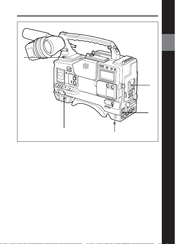
2-1 Power Supply
3
5
4
Power supply functions
1 Battery attachment
Attach a BP-L60/L90 Battery Pack, a DC-L1 Battery Adaptor for
loading an NP-1B Battery Pack, or a DC-L90 Battery Adaptor for
loading a BP-90A Battery Pack.
Furthermore, by attaching an AC-DN1/DN2 AC Adaptor you can
operate the camcorder from AC power.
2
Locations and Functions of Parts and Controls
1
2
2 DC IN (external power input) connector (XLR type, 4-pin, male)
Connect an AC-550/550CE AC Adaptor with the DC output cable
supplied with the adaptor.
To use an external battery, connect its DC output cable to the DC IN
connector.
Chapter 2 Locations and Functions of Parts and Controls 2-1

3 BREAKER button
Excessive current in the internal circuitry, whatever the cause, will trip
the internal circuit breaker, automatically cutting off the power. If the
breaker trips, consult your Sony service personnel.
2
4 POWER switch
This switch turns the main power supply on and off.
5 LIGHT switch
This selects the way in which a video light connected to the LIGHT
connector is switched on and off.
AUTO: When the video light switch is turned on, starting recording with
the VTR turns on the light.
MANUAL: The video light switch controls the light, turning it on and
off manually.
2-2 Chapter 2 Locations and Functions of Parts and Controls

2-2 Accessory Attachments
1 2
3
4
5
6
2
98
Lens cable clamps
Accessory attachments
1 Shoulder strap posts
Attach the supplied shoulder strap to these posts.
2 Light shoe
Attach a video light, etc. to this shoe.
Chapter 2 Locations and Functions of Parts and Controls 2-3
7

3 LIGHT connector
Connect the cable of a video light attached to the light shoe. The
maximum power consumption allowable for the video light is 30 W.
2
4 Lens mount
This is a special bayonet type lens mount.
5 Lens locking lever
After inserting the lens in the lens mount, rotate the lens mount ring with
this lever to lock the lens in position.
6 Lens mount cap
Remove this cap by pushing up on the lens locking lever. For protection
from dust, always insert this cap when no lens is mounted.
7 Tripod mount
Fit the supplied tripod adaptor to mount the camcorder on a tripod.
8 LENS connector (12-pin)
Fit the lens cable to this connector. Contact your Sony representative for
more information about the lens you are using.
9 Shoulder pad
You can move the shoulder pad forwards or backwards by loosening the
two screws. Do this to ensure the best balance when shooting with the
camcorder on your shoulder.
2-4 Chapter 2 Locations and Functions of Parts and Controls
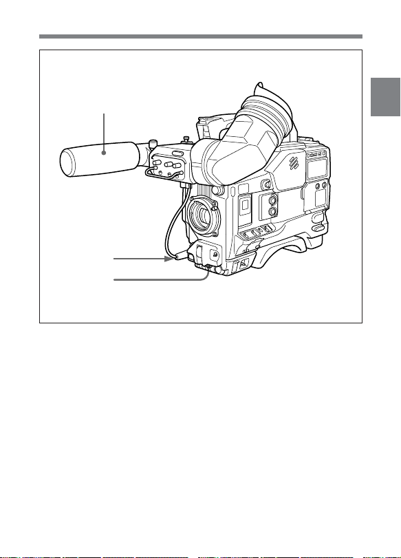
2-3 Audio Functions
1
2
3
Audio functions (1)
1 Microphone
This is a super-cardioid directional microphone with an external power
supply system. You can use it as an interview microphone by connecting
it to an extension cable (not supplied).
2 MIC IN (microphone input) connector (XLR type, 3-pin, female)
The supplied microphone connects to this connector. By using an
extension cable (not supplied), you can connect a microphone other than
the supplied one as long as it is provided with an external power supply
system. The connector supplies power (+48 V) to the microphone.
2
Chapter 2 Locations and Functions of Parts and Controls 2-5

3 MIC (microphone) AUDIO LEVEL control
If one or both of the AUDIO IN switches are set to FRONT, you can
adjust the recording level of the microphone.
When AUDIO is set to ON in the VF DISPLAY 2/2 page of the setup
2
menu and the viewfinder DISPLAY switch is set to ON, adjust the
channel-1 audio level, watching the indication in the viewfinder.
2-6 Chapter 2 Locations and Functions of Parts and Controls
 Loading...