

Page 1

Digital
Photo Camera
3-859-629-13(1)
Operating Instructions
Before operating this unit, please read this manual
thoroughly and retain it for future reference.
DKC-ST5
1997 by Sony Corporation
Page 2

Owner’s Record
The model and serial numbers are located at the rear.
Record the serial number in the space provided below.
Refer to these numbers whenever you call upon your Sony
dealer regarding this product.
Important Notice
Thank you for choosing the Sony DKC-ST5 Digital Photo
Camera (referred to below as “the product”). The DKC-ST5
control software (referred to below as “the software”) is
included with the product as sample software in order to
enable you to utilize the full potential of the product.
The software is provided under the following conditions.
WARNING
To prevent fire or shock hazard, do not
expose the unit to rain or moisture.
To avoid electrical shock, do not open the
cabinet. Refer servicing to qualified
personnel only.
For the customers in the USA
This equipment has been tested and found to comply with
the limits for a Class A digital device, pursuant to Part 15 of
the FCC Rules. These limits are designed to provide
reasonable protection against harmful interference when the
equipment is operated in a commercial environment. This
equipment generates, uses, and can radiate radio frequency
energy and, if not installed and used in accordance with the
instruction manual, may cause harmful interference to radio
communications. Operation of this equipment in a residential
area is likely to cause harmful interference in which case the
user will be required to correct the interference at his own
expense.
1. The software and related documentation may not be
reproduced, copied, modified, or revised in any manner,
in whole or in part.
2. The software can only be used with the product, and may
not be used by any third party. Export or transfer of the
product and the software to any foreign country is
prohibited.
3. The software may not be disassembled, decompiled, or
otherwise converted to source code form.
4. The software is provided only as a sample, and Sony
makes no assurance whatsoever concerning the
software’s freedom from defects.
5. Sony disclaims all responsibility for any copyright, patent,
or other non-tangible property infringement disputes that
may arise with third parties as a consequence of use of
the software.
6. If you determine that you have no need for the software,
please destroy the diskette on which it is provided and
the accompanying documentation.
Except as otherwise provided by law, unauthorized use of
recorded tapes, disks, or broadcast programs is a
violation of copyright laws. Therefore, please be sure to
obtain proper authorization before using such materials.
You are cautioned that any changes or modifications not
expressly approved in this manual could void your authority
to operate this equipment.
The shielded interface cable recommended in this manual
must be used with this equipment in order to comply with the
limits for a digital device pursuant to Subpart B of Part 15 of
FCC Rules.
2
Page 3

Table of Contents
Chapter 1
About This Manual ............................................................5
Overview
Chapter 2
Operation
System Features ...............................................................7
DKC-ST5 Standard Product Configuration ........................ 8
Principal Examples of Use .................................................. 9
Location and Function of Parts .....................................11
Camera Head ..................................................................... 11
Digital Processor ............................................................... 13
Remote Controller ............................................................. 16
Powering On and Off.......................................................21
Powering On...................................................................... 22
Powering Off ..................................................................... 22
Live and Memory Monitor Modes .................................... 22
Status Indications .............................................................. 23
Image Adjustments and Focusing.................................24
Adjusting the Zoom........................................................... 24
Focusing ............................................................................ 24
Chapter 3
Installation and
Connections
Adjusting the Black Balance..........................................26
Adjusting the White Balance ..........................................27
Adjusting the Iris.............................................................30
Using the AE Function....................................................31
Shooting...........................................................................35
Basic Procedure................................................................. 35
Selecting a Memory .......................................................... 37
Reviewing a Captured Image ............................................ 42
Switching Between Landscape and
Portrait Orientations ..................................................... 43
Installing the Camera Head ............................................45
Connections ....................................................................46
SCSI Connections ...........................................................48
Setting the DIP Switches ................................................50
Table of Contents 3
Page 4

Table of Contents
Chapter 4
Menus
Chapter 5
Using the Control
Software
Overview ..........................................................................51
Basic Menu Operation Procedure .................................52
Menu Settings..................................................................55
Main Menu ........................................................................ 55
Live Menu ......................................................................... 58
Overview ..........................................................................59
Required Hardware ........................................................... 59
Required Software............................................................. 59
Installinzg the Control Software ....................................60
Preparations ....................................................................... 60
Installing the Control Software ......................................... 60
Using the Control Software............................................... 61
Uninstalling the Control Software..................................... 61
Chapter 6
Maintenance
Appendix
Error Messages ...............................................................63
Troubleshooting ..............................................................64
Notes on Use ...................................................................65
Specifications..................................................................66
4 Table of Contents
Page 5

About This Manual
This manual gives an overview of the DKC-ST5 Digital Photo Camera,
and describes connections and installation, and the method of operation,
principally with a remote controller.
Using the supplied control software
By installing the DKC-ST5 Control Software supplied with the product on
3.5-inch floppy disks, you can control the DKC-ST5 from a computer. For
details of the operation of the software, read the Readme files installed
with the control software.
For details of the installation of the control software, see Chapter 5 of this
manual.
About This Manual 5
Page 6

Page 7

System Features
Chapter 1 Overview
The DKC-ST5 Digital Photo Camera is a high-quality
electronic photography system, using a high-resolution
CCD camera with a total of 1,400,000 pixels. This
system can form the core of a studio portrait
photography system, or can be used for a variety of
applications in which still images are kept in a filing
system.
A maximum of nine images can be held in memory.
Stored images can also be transferred to a computer for
processing.
The following are some of the principal features of the
system.
High-resolution CCD camera head
The camera head uses a three-chip 2/3-inch highresolution CCD with 1,400,000 total pixels.
Storage for up to nine images
Images can be captured into memory consecutively at
about 1-second intervals. After checking captured
images on a monitor, you can select the images for
transfer to a computer.
Simple camera operation
The procedure for using the camera is similar to that
for a conventional camera, so there are no particular
problems for users unaccustomed to video cameras or
digital devices.
Lens mount
In addition to the special-purpose lens (VCL1205BYS), you can fit any
mount lens.
2
/3-inch 48-mm bayonet
Chapter 1 Overview
Flexible color gradation representation
The A/D conversion uses a 10-bit lookup table, which
makes for flexible color gradation representation.
Optimized dynamic range
Gamma correction and knee point adjustment allow
the dynamic range to be optimized.
Special-purpose lens for smooth manual
adjustment
The special-purpose lens (VCL-1205BYS) is available
separately, and provides a focusing ring and zoom ring
with a light touch, allowing for smooth manual
adjustment.
Chapter 1 Overview 7
Page 8
System Features
DKC-ST5 Standard Product Configuration
Chapter 1 Overview
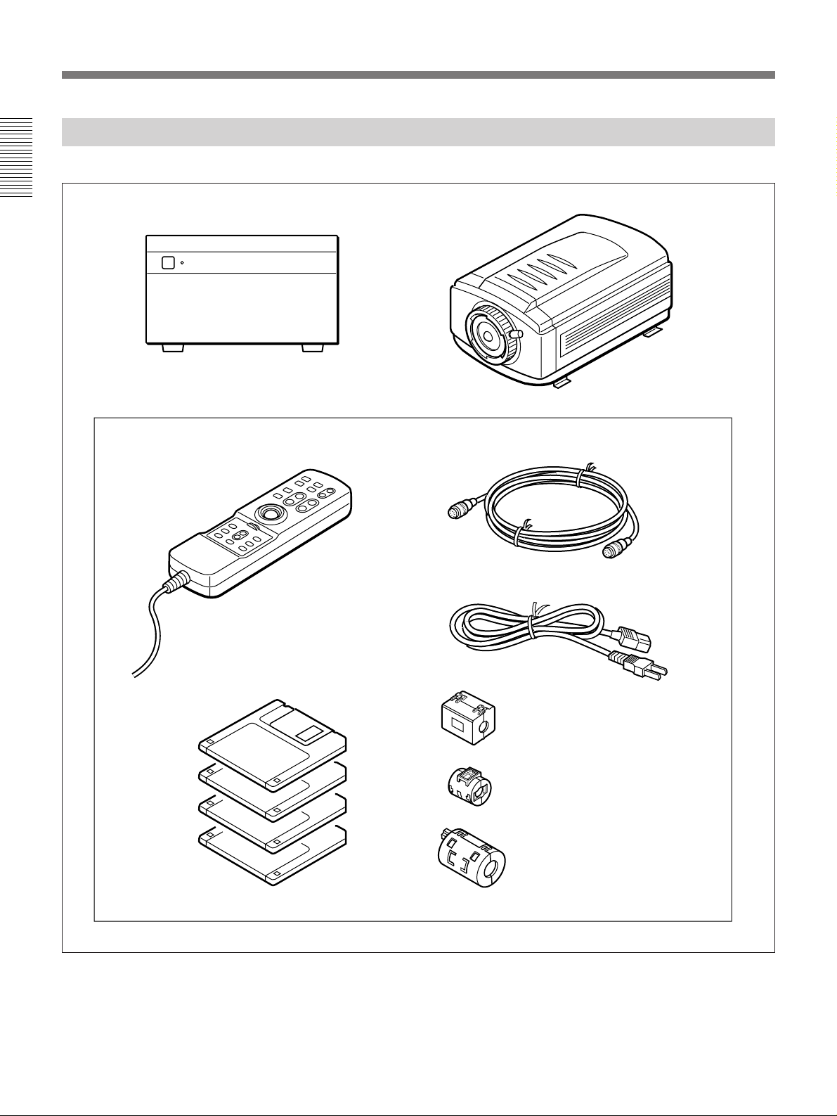
The following is the standard product configuration of the DKC-ST5.
Digital processing unit Camera head
The following items are also supplied as standard accessories.
Remote controller
Four 3.5-inch floppy disks
containing the Control Software
Camera cable
AC cord
Ferrite cores
Type A: ×2
Type B: ×2 for NTSC model,
×3 for PAL model
Type C: ×2 (for PAL model only)
8 Chapter 1 Overview
Operating Instructions (this manual)
In addition to the standard components, a lens, video monitor, and
computer are required.
For details of the components required in addition to the standard product
configuration, see the section “Principal Examples of Use” on the next page.
Page 9
Principal Examples of Use
Portrait system
Generator
Flash
Remote controller
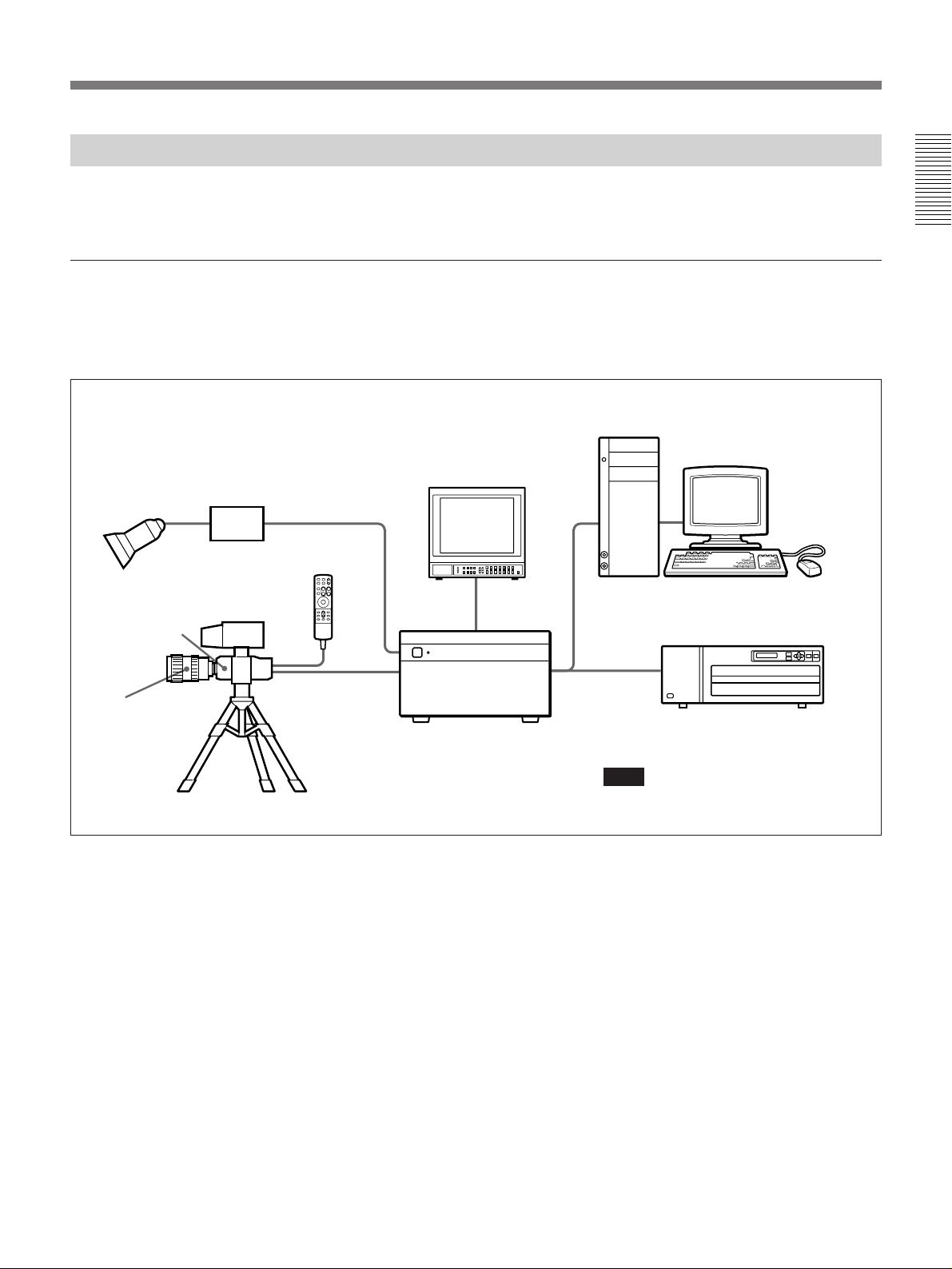
The following are examples of use of the DKC-ST5 Digital Photo Camera
system.
Chapter 1 Overview
By combining a computer and a full-color printer, you can build an instant
portrait system as shown below. You can capture a number of images into
memory, review them on the monitor, then print a selected image.
Computer
Monitor
Camera head
Lens
(VCL-1205BYS)
Viewfinder
Camera Cable (10 m)
(supplied)
SCSI cable
SCSI cable
UP-D8800
Digital processing unit
Note
Do not connect or disconnect the cables when
any system component is powered on.
Chapter 1 Overview 9
Page 10
System Features
Still image filing system
Chapter 1 Overview
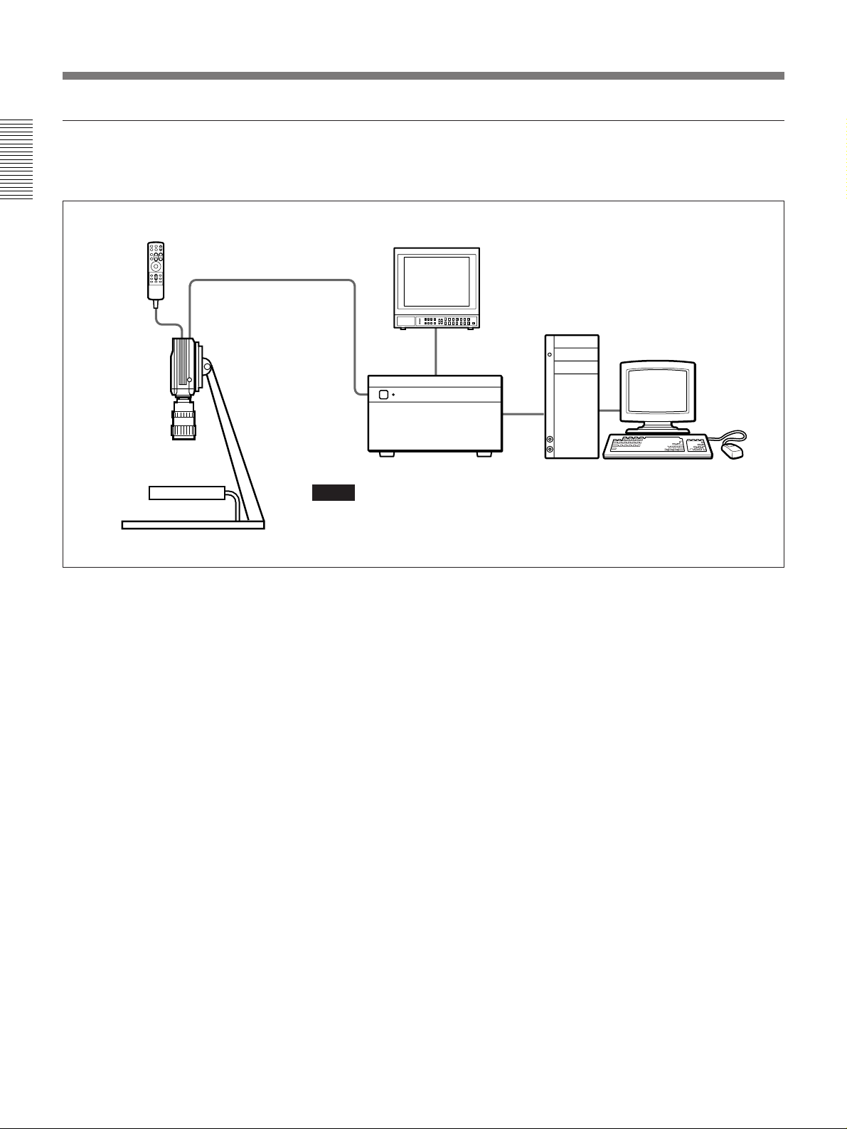
In combination with a computer, you can create a still image filing system
as shown below.
Remote
controller
Camera head
Lens
(VCL-1205BYS)
f Parts
Camera Cable (10 m)
Monitor
(supplied)
Computer
SCSI
cable
Digital processing unit
Notes
• Do not connect or disconnect the cables when any system component is powered on.
• When you use the camera in such a system configuration as illustrated, select “CAMERA”
in the main menu and set the “ROTATE” item to “OFF”.
For details of menu operations, see Chapter 4.
10 Chapter 1 Overview
Page 11
Location and Function of Parts
Camera Head
Front view
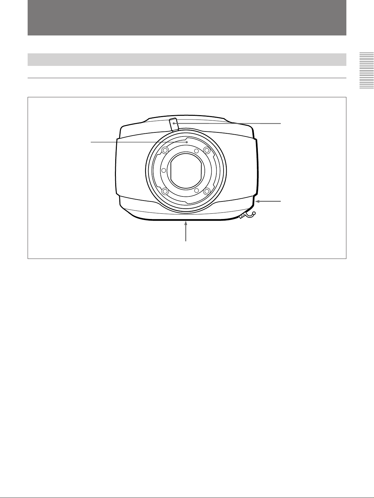
1 Lens mount
Chapter 1 Overview
2 Lens locking lever
3 LENS2 connector
1 Lens mount
Mount the lens here. With the back end of the lens
inserted, press down the lens locking lever in a
clockwise direction to lock the lens.
In addition to the special-purpose lens (VCL-
2
1205BYS), you can fit any
/3-inch 48-mm bayonet
mount lens.
2 Lens locking lever
This locks the lens as described under “1 Lens
mount.”
4 Mounting hole
3 LENS2 connector (12-pin, female)
When using a lens other than the special-purpose one
(VCL-1205BYS), connect the cable from the lens to
this connector.
4 Mounting hole
This accepts the fixing screw when the camera head is
mounted on a tripod.
Chapter 1 Overview 11
Page 12
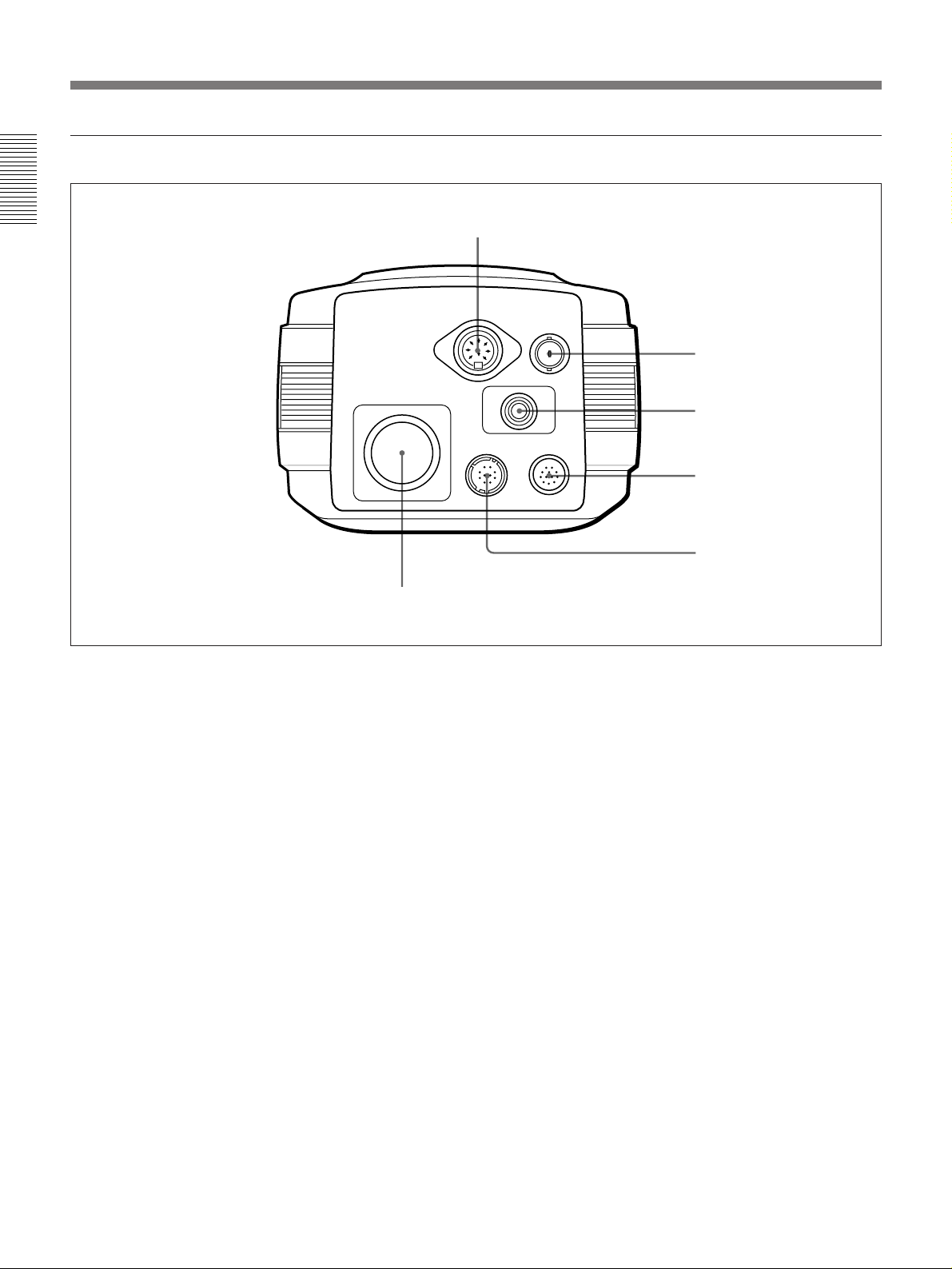
Location and Function of Parts
Rear view
Chapter 1 Overview
1 VF connector
VF
PROCESSOR
LENS1
6 PROCESSOR connector
MONITOR
2 MONITOR connector
FLASH
3 FLASH connector
REMOTE
4 REMOTE connector
5 LENS1 connector
1 VF (viewfinder) connector (DIN 8-pin)
Connect the cable from the viewfinder.
2 MONITOR connector (BNC type)
This outputs a composite video signal. Using a
75-ohm coaxial cable (not supplied), connect this to
the composite video input connector (BNC type) of a
video monitor.
3 FLASH connector (X-contact socket)
Connect the cable from a flash unit.
This connector is not used when the cable from the
flash unit is connected to the FLASH connector on the
digital processor.
4 REMOTE connector (12-pin, female)
Connect the supplied remote controller.
5 LENS1 connector (20-pin, female)
When using the special-purpose lens (VCL-1205BYS),
connect the cable from the lens.
6 PROCESSOR connector (26-pin, male)
Connect this to the CAMERA connector of the digital
processor with the supplied camera cable.
12 Chapter 1 Overview
Page 13
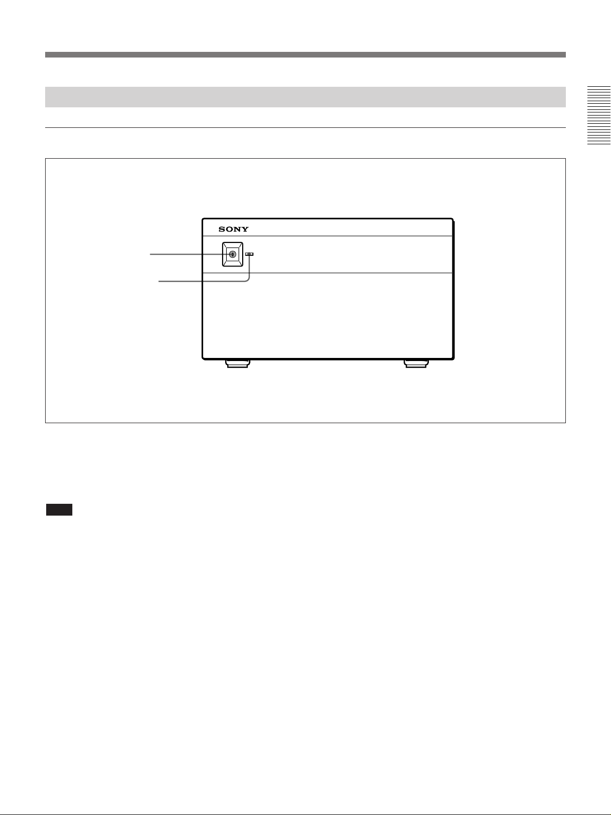
Digital Processor
Front panel
1 POWER switch
2 POWER indicator
Ø
POWER
ON
1
/
Chapter 1 Overview
®
OFF
ø
1 POWER switch
Press this in to power on the digital processor. Press it
once more to power off.
Note
Once you have powered off the digital processor, do
not try to power it on again immediately. Doing this
may result in failure anyway.
2 POWER indicator
This lights when the digital processor is powered on.
Chapter 1 Overview 13
Page 14

Location and Function of Parts
Rear panel
Chapter 1 Overview
1 MODE SELECT switches
2 SCSI In and SCSI Out connectors
MODE SELECT
SCSI FLASH
SCSI In
SCSI Out
MONITOR REMOTE CAMERA
VIDEO S-VIDEO
R G B SYNC
8 MONITOR connectors
3 FLASH connector
RS-232C
FS
6 REMOTE RS-232C connector
7 REMOTE FS connector
4 ⁄ AC IN connector
AC IN
⁄
5 CAMERA connector
1 MODE SELECT switches
These eight DIP switches select the SCSI ID of the
digital processor, the attenuation compensation setting
for the camera cable, and other settings.
For details of the settings of these switches, see the section
“Setting the DIP Switches” on page 50.
2 SCSI In and SCSI Out connectors (50-pin, highdensity)
Use these to connect to other SCSI devices (computer,
printer, and so forth).
For details of the SCSI connections, see the section “SCSI
Connections” on page 48.
3 FLASH connector (X-contact socket)
Connect the cable from a flash unit.
This connector is not used when the cable from the
flash unit is connected to the FLASH connector on the
camera head.
4 ⁄ AC IN connector
Use the supplied power cord to connect to a 120 V AC
(NTSC model) or 220 to 240 V AC (PAL model)
power outlet.
5 CAMERA connector (26-pin, female)
Connect this to the PROCESSOR connector of the
camera head with the supplied camera cable.
6 REMOTE RS-232C connector (D-sub 9-pin,
female)
(Undefined.)
7 REMOTE FS (foot switch) connector (minijack)
Connect the cable from a foot switch.
14 Chapter 1 Overview
Page 15

8 MONITOR connectors
These connectors output signals for input to a video
monitor.
VIDEO output connector (BNC type): Using a
75-ohm coaxial cable (not supplied), connect this
to the composite video input connector (BNC
type) of the monitor.
S-VIDEO output connector (Mini-DIN,
4-pin): Using an S-video cable (not supplied),
connect this to the S-video input connector of the
monitor.
R, G, B, and SYNC output connectors (BNC type):
Using 75-ohm coaxial cables (not supplied),
connect these to the RGB and sync input
connectors of the monitor.
Chapter 1 Overview
Chapter 1 Overview 15
Page 16
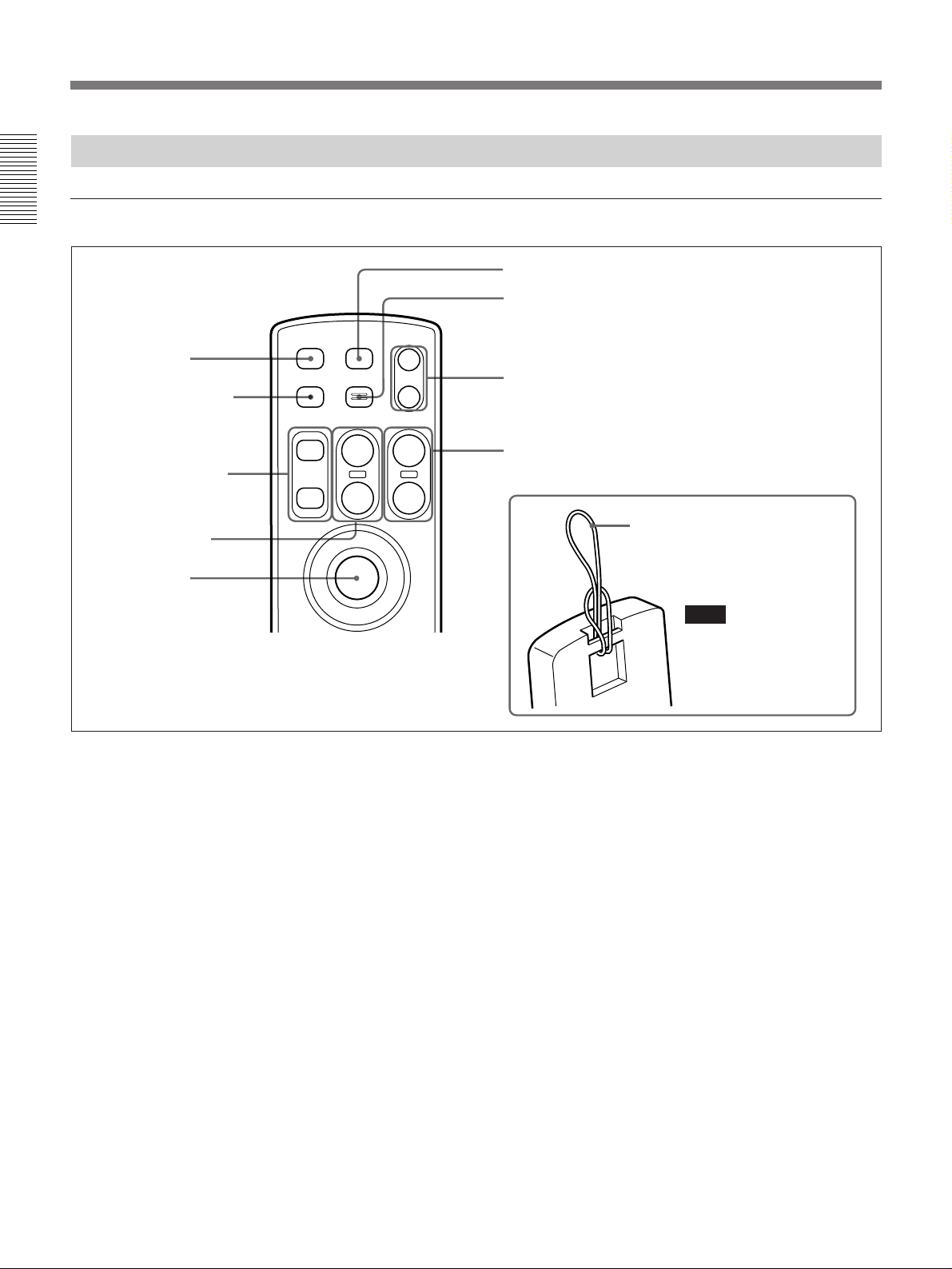
Location and Function of Parts
Remote Controller
Upper section
Chapter 1 Overview
6 USER button
7 E-ZOOM button
1 STDBY button
2 LIVE/MEMORY button
3 MEMORY +/– buttons
4 FOCUS FAR/NEAR
buttons
5 Release button
STDBY USER
LIVE/MEMORY E-ZOOM
MEMORY FOCUS ZOOM
+
FAR
NEAR
--
IRIS
+
--
T
W
1 STDBY (standby) button
When using a lens other than the special-purpose lens
(VCL-1205BYS), pressing this button puts the camera
into the standby mode, and stops down the iris to the
current setting.
2 LIVE/MEMORY button
Pressing this button toggles between the live and
memory monitor modes.
Live mode: The image from the camera lens is
output to the monitor. At this point the lens iris is
automatically in the fully-open position.
Memory mode: The image saved in the currently
selected memory is output to the monitor.
8 IRIS +/– buttons
9 ZOOM T/W buttons
Hang the loop of string on the
tripod or some other safe place.
Note
The remote controller has a
slot in the back, through
which you can thread a loop
of string.
3 MEMORY +/– buttons
In the memory monitor mode, these buttons select the
memory.
MEMORY +: Pressing this button switches from the
currently selected memory to the next higher
numbered memory (1 n 2 n 3 ... ).
MEMORY –: Pressing this button switches from the
currently selected memory to the next lower
numbered memory (9 n 8 n 7 ... ).
4 FOCUS FAR/NEAR buttons
These adjust the focus.
FOCUS FAR: Pressing this button focuses further
away.
FOCUS NEAR: Pressing this button focuses closer
to the camera.
16 Chapter 1 Overview
Page 17

5 Release button
Press this button to take a picture.
Using the special-purpose lens (VCL-1205BYS):
Pressing this button instantaneously stops down
the iris to the current setting, and captures the
image to memory.
Using other lenses: If the camera is in standby mode,
pressing this button instantaneously captures the
image to memory. If not in standby mode, the iris
is first stopped down to the current setting (which
takes several seconds), and then the image is
captured to memory.
6 USER button
When using the Control Software, press this button to
recall user files (USER1, USER2, and USER3).
Recalling one of these files automatically sets up the
system according to the settings in the file. You can
also use this button to switch from one user file to
another.
For details of the Control Software, see Chapter 5.
7 E-ZOOM (electronic zoom) button
Pressing this button zooms in at a 2:1 ratio on the
center of the live image (E-ZOOM mode). Use this
button to focus quickly. Pressing the button once more
exits the E-ZOOM mode, and returns to the normal
image.
Note
In the E-ZOOM mode, only the FOCUS FAR/NEAR
and ZOOM T/W buttons operate.
8 IRIS +/– buttons
These adjust the lens iris.
IRIS +: Pressing this button increases the numerical
value of f-stop (i. e. stop down the iris).
IRIS –: Pressing this button decreases the numerical
value of f-stop (i. e. open up the iris).
9 ZOOM T/W (telephoto/wide angle) buttons
These control the zoom.
ZOOM T: Pressing this button zooms in.
ZOOM W: Pressing this button zooms out.
Chapter 1 Overview
Chapter 1 Overview 17
Page 18

Location and Function of Parts
Lower section
Chapter 1 Overview
Pull down the lid.
!¢ and buttons
!º MENU button
!¡ WB (STILL) button
!™ WB (LIVE) button
!£ BB button
0 MENU button
Press this button to access the menus.
Press and release quickly to display the main menu on
the monitor screen. Press once more to clear the menu
from the monitor screen.
Hold down the button for at least two seconds to
display the live menu.
For details of the menus, see Chapter 4.
MENU ENTER
WB(STILL)
WB(LIVE)
CHARACTER
BB
FRAME
ON/OFF
ON/OFF
!∞ ENTER button
!§ FRAME ON/OFF button
!¶ CHARACTER ON/OFF button
!™ WB (white balance) (LIVE) button
Hold this button down for at least two seconds to
adjust the white balance for the live image output.
This carries out the white balance adjustment
automatically, with the lens iris in the fully open
position.
For details of the procedure for white balance adjustment,
see page 27.
!¡ WB (white balance) (STILL) button
Hold this button down for at least two seconds to
adjust the white balance for the still image captured to
memory. This carries out the white balance
adjustment automatically, with the lens iris stopped
down to the current setting.
For details of the procedure for white balance adjustment,
see page 27.
18 Chapter 1 Overview
!£ BB (black balance) button
Hold this button down for at least two seconds to
adjust the black balance.
For details of the procedure for black balance adjustment,
see page 26.
!¢ and buttons
Press these buttons to move the cursor on the menu
screen up and down. Also use them to adjust setting
values of certain menu items.
For details of the menus, see Chapter 4.
Page 19

!∞ ENTER button
Press this button to go down to the next level of the
menus, and also to confirm settings made within the
menus.
For details of the menus, see Chapter 4.
!§ FRAME ON/OFF button
When using the supplied control software, press this
button to toggle on and off the display on the monitor
screen of a frame showing the effective print area,
horizontal and vertical coordinate axes, and a
background image.
The factory default setting is for this display function
to be disabled.
For details of the control software, see Chapter 5.
!¶ CHARACTER ON/OFF button
Press this button to toggle the status display on the
monitor screen between the on and off settings. The
factory default setting is for the status display to be
enabled.
The status display indicates the live or memory
monitor mode, the iris setting, and the memory
selection and availability.
Chapter 1 Overview
Chapter 1 Overview 19
Page 20

Page 21

Powering On and Off
Powering On
Use the following procedure to power on.
Notes
•When using the system for the first time, before powering on be sure to
set the DIP switches appropriately.
•When you are using a Power Macintosh
Computer, Inc., execute Step 3 before Step 2.
1)
computer from Apple
Chapter 2 Operation
For details of the settings of the DIP switches, see page 50.
1 Power on the monitor, printer, and other peripheral devices.
For details, refer to the user documentation provided with the peripheral
devices.
2 Power on the digital processor (press in the POWER switch on the
front panel).
If the “BEEP” item in the OTHERS menu is set to “ON” (the factory
default setting), then the digital processor emits a double beep about
five seconds after it is powered on, indicating that it is ready for
operation.
For details of the menus, see Chapter 4.
When the digital processor is ready for operation, the system
automatically switches to the live monitor mode, and the mode
indication “LIVE” is displayed on the monitor screen.
For details of the live monitor mode, see the section “Live and Memory
Monitor Modes” on the next page.
For details of the operating mode indication, see the section “Status
Indications” on page 23.
Chapter 2 Operation
3 If you are using a computer, power on the computer.
For details, refer to the user documentation provided with the computer.
Note
If you power on the computer before the digital processor is ready for
operation (after the double beep), the computer may not start up
correctly.
......................................................................................................................................................................................
1) Power Macintosh is a trademark of Apple Computer, Inc.
Chapter 2 Operation 21
Page 22

Powering On and Off
Powering Off
Chapter 2 Operation
Live and Memory Monitor Modes
Use the following procedure to power off.
1 If you are using a computer, power off the computer.
For details, refer to the user documentation provided with the computer.
2 Power off the digital processor (press the POWER switch on the front
panel).
3 Power off the monitor, printer, and other peripheral devices.
Pressing the LIVE/MEMORY button on the remote controller toggles
between the live and memory monitor modes.
•In the live monitor mode, the image from the camera is output to the
monitor. At this point the lens iris is automatically in the fully-open
position, regardless of the current setting, and “LIVE” appears in the
status indication on the monitor in the position indicating the mode.
•In the memory monitor mode, the image saved in the memory currently
selected with the MEMORY +/– buttons is output to the monitor.
“MEMORY” appears in the status indication on the monitor in the
position indicating the mode, together with the selection and availability
of the memories (1 to 9).
22 Chapter 2 Operation
For details of the memory status indication, see the next section.
Page 23
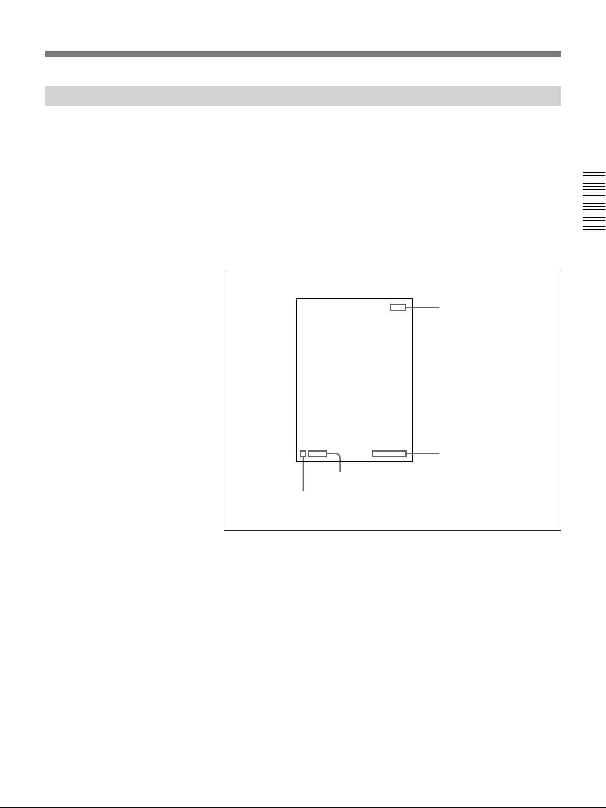
Status Indications
Pressing the CHARACTER ON/OFF button on the remote controller
toggles the status display on the monitor screen between the on and off
settings.
•When the status display is in the “on” mode, it indicates the live or
memory monitor mode, the iris setting, and the memory status (selection
and availability of each memory).
•Even when the status display is in the “off” mode, the status display
appears, but disappears again after a few seconds.
Chapter 2 Operation
The following illustration shows the positions of the various status
indication items.
Operating mode
Iris setting (f-stop)
FLASH ON/OFF
Memory status
Chapter 2 Operation 23
Page 24
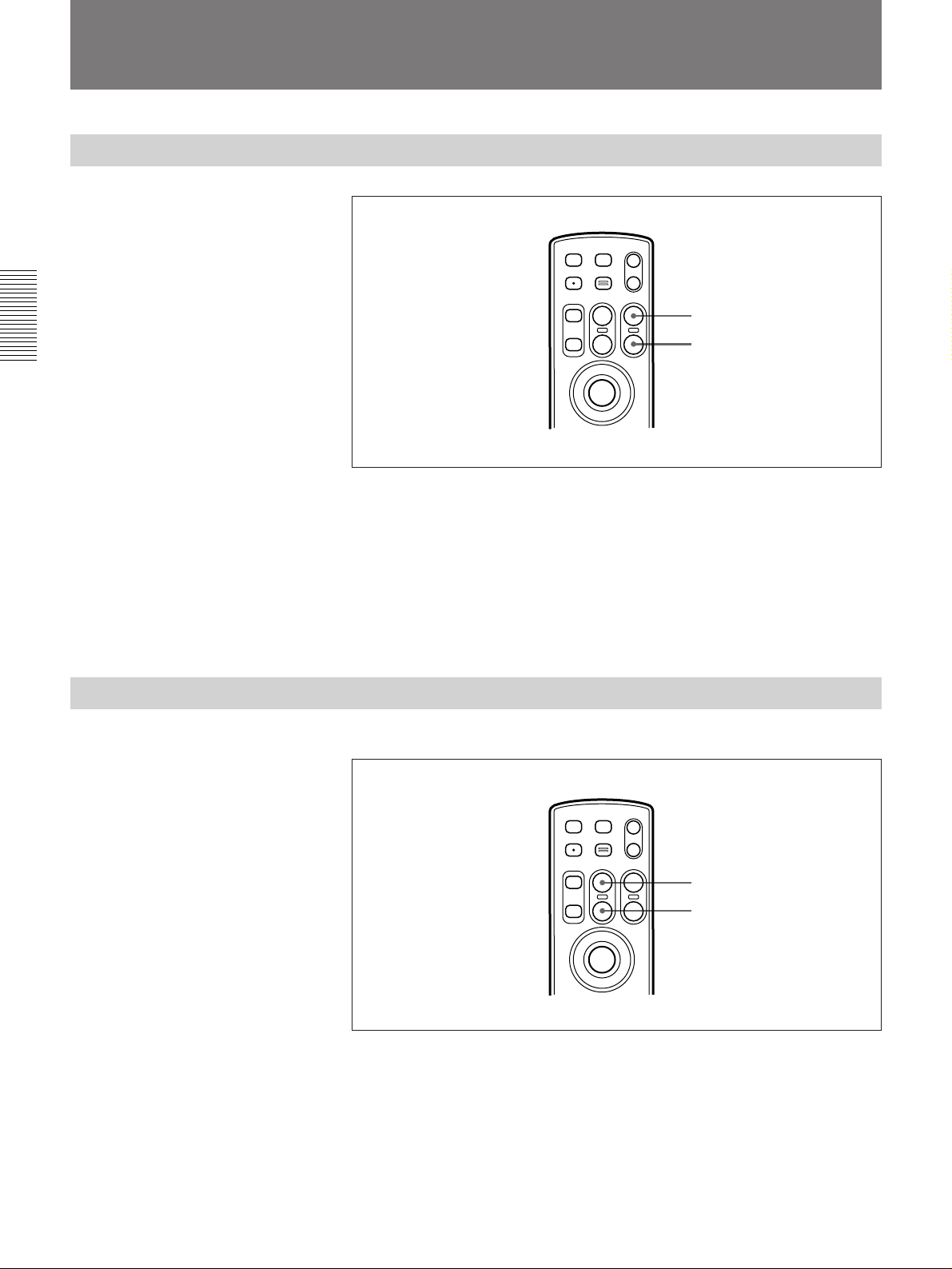
Image Adjustments and Focusing
Adjusting the Zoom
Chapter 2 Operation
Focusing
STDBY USER
LIVE/MEMORY E-ZOOM
MEMORY FOCUS ZOOM
+
--
NEAR
IRIS
+
--
FAR
T
W
ZOOM T button
ZOOM W button
To zoom in
Press the ZOOM T (telephoto) button on the remote controller.
To zoom out
Press the ZOOM W (wide angle) button on the remote controller.
To adjust the zoom angle manually
Set the lens to manual zoom mode, and turn the zoom ring.
Focusing without changing the zoom angle
STDBY USER
LIVE/MEMORY E-ZOOM
MEMORY FOCUS ZOOM
+
--
NEAR
IRIS
+
--
FAR
T
W
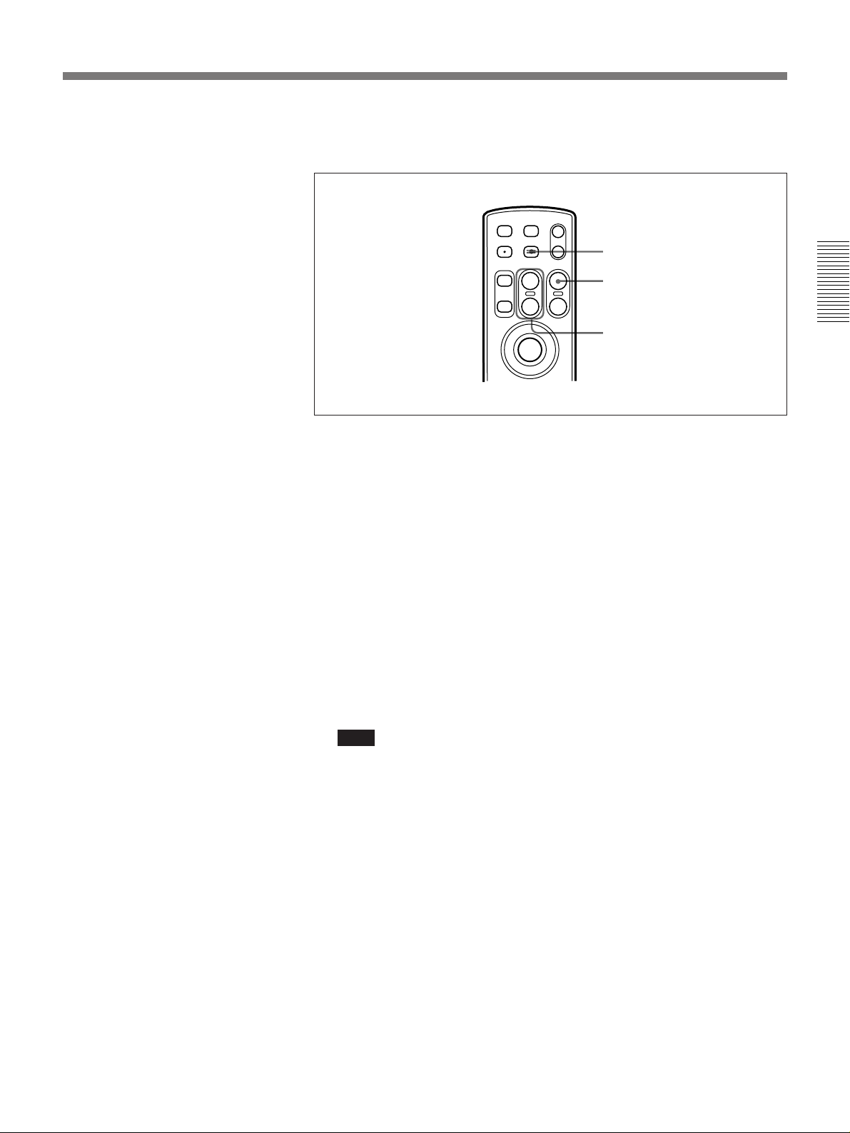
FOCUS FAR button
FOCUS NEAR button
•To focus further away, press the FOCUS FAR button on the remote
controller.
•To focus closer, press the FOCUS NEAR button on the remote controller.
•To focus manually, set the lens to manual focusing mode, and turn the
focusing ring.
24 Chapter 2 Operation
Page 25
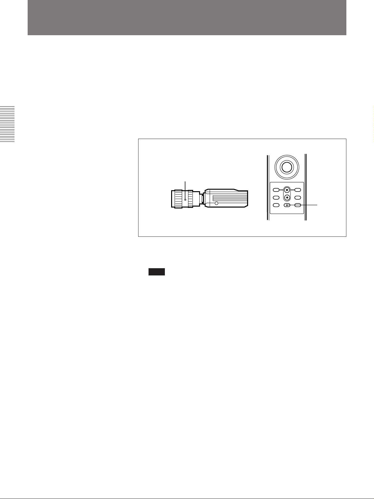
For most accurate focusing
STDBY USER
LIVE/MEMORY E-ZOOM
IRIS
MEMORY FOCUS ZOOM
FAR
NEAR
T
W
+
--
+
--
1
2,4
3
Using the E-ZOOM function, you can focus more accurately.
1 Press the ZOOM T button on the remote controller, to select the
narrowest telephoto angle.
2 Press the E-ZOOM button.
Chapter 2 Operation
This switches to the E-ZOOM mode, and zooms in at a 2:1 ratio on the
center of the image.
3 Press the FOCUS FAR button or FOCUS NEAR button to adjust the
focus.
4 Press the E-ZOOM button.
This exits the E-ZOOM mode, and returns to the normal image.
Note
Until you exit from the E-ZOOM mode, only the FOCUS FAR/NEAR
and ZOOM T/W buttons operate.
Chapter 2 Operation 25
Page 26
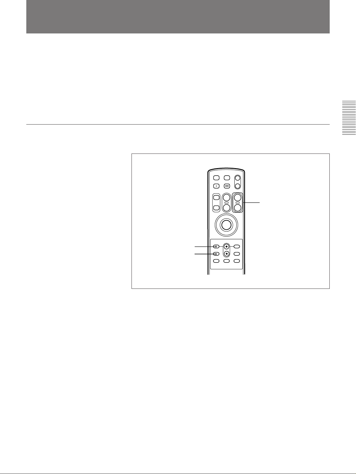
Chapter 2 Operation
Adjusting the Black Balance
To obtain images with a natural color balance, carry out black balance
adjustment in the following cases. The adjustment setting is preserved for
about ten years, even when the unit is powered off.
•When using the camera for the first time
•When you have replaced the camera
•When the camera has not been used for a long interval
•When the ambient temperature has changed greatly
•At the change of the seasons
Use the following procedure to carry out black balance adjustment.
1
MENU ENTER
WB(STILL)
WB(LIVE)
BB
FRAME
ON/OFF
CHARACTER
ON/OFF
2
1 Check that the lens is in automatic iris mode.
Note
If you are using a lens with no automatic iris function, close the iris
completely.
2 Hold down the BB button on the remote controller for at least two
seconds.
This automatically closes the lens iris completely, and carries out black
balance adjustment. The message “Reading Color Table...” appears on
the monitor screen.
The image on the monitor screen may flicker while the adjustment is in
progress, but this is not a fault.
When the adjustment is completed, the message “BB:OK” appears.
If the adjustment was not achieved
The message “BB:NG Please try again” appears. Repeat the above
procedure.
26 Chapter 2 Operation
Page 27
Adjusting the White Balance
To obtain images with a natural color balance, carry out white balance
adjustment in the following cases. The adjustment setting is preserved for
about ten years, even when the unit is powered off.
•When using the camera for the first time
•When the lighting conditions change
This system keeps separate white balance settings for the still images
captured to memory and the live image output to the monitor.
Adjusting the white balance for still images
After setting up the lighting, use the following procedure.
Chapter 2 Operation
1
3
STDBY USER
LIVE/MEMORY E-ZOOM
MEMORY FOCUS ZOOM
+
--
MENU ENTER
WB(STILL)
WB(LIVE)
NEAR
IRIS
+
--
FAR
T
W
FRAME
ON/OFF
CHARACTER
ON/OFF
BB
2
1 Press the MENU button on the remote controller to access the main
menu, and make the following settings.
•Select the PICTURE menu, and set “C-TEMP” to “AWB” (this is the
factory default setting).
•Select the FLASH menu, and if using a flash, set the “FLASH” item
to “ON” (this is the factory default setting). Next select the flash
interval with the “INTERVAL” item.
If not using a flash, set the “FLASH” item to “OFF.”
For details of menu operations, see Chapter 4.
2 Under the same lighting conditions as for shooting, position a white
subject (white pattern, white cloth, etc.), and zoom in so that it fills the
screen.
(Continued)
Chapter 2 Operation 27
Page 28

Adjusting the White Balance
3 Hold down the WB (STILL) button on the remote controller for at least
two seconds.
This automatically starts white balance adjustment. The message
“Reading Color Table...” appears on the monitor screen.
If the FLASH menu setting is “FLASH ON”, the flash flashes several
times.
When the adjustment is completed, the message “WB:OK” appears.
Chapter 2 Operation
If the adjustment was not achieved
The message “WB:NG Please try again” appears. Repeat the above
procedure.
28 Chapter 2 Operation
Page 29
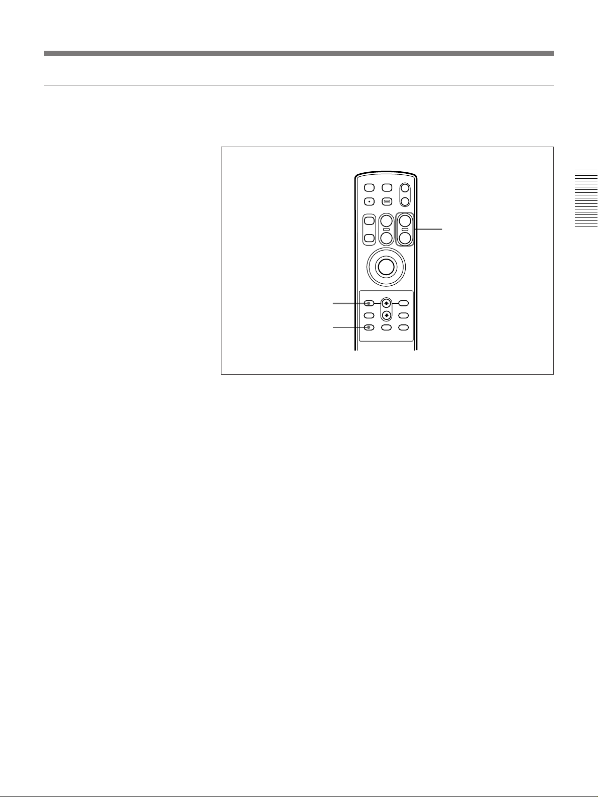
Adjusting the white balance for live images
After setting up the lighting, in live monitor mode use the following
procedure.
1
STDBY USER
LIVE/MEMORY E-ZOOM
MEMORY FOCUS ZOOM
+
--
MENU ENTER
WB(STILL)
WB(LIVE)
NEAR
IRIS
+
--
FAR
T
W
FRAME
ON/OFF
CHARACTER
ON/OFF
BB
2
3
1 Hold down the MENU button on the remote controller for at least two
seconds to access the live menu, and set “C-TEMP” to “AWB”.
For details of menu operations, see Chapter 4.
2 Under the same lighting conditions as for shooting, position a white
subject (white pattern, white cloth, etc.), and zoom in so that it fills the
screen.
Chapter 2 Operation
3 Hold down the WB (LIVE) button on the remote controller for at least
two seconds.
This automatically starts white balance adjustment. The message
“Reading Color Table...” appears on the monitor screen.
When the adjustment is completed, the message “WB:OK” appears.
If the adjustment was not achieved
The message “WB:NG Please try again” appears. Repeat the above
procedure.
Chapter 2 Operation 29
Page 30
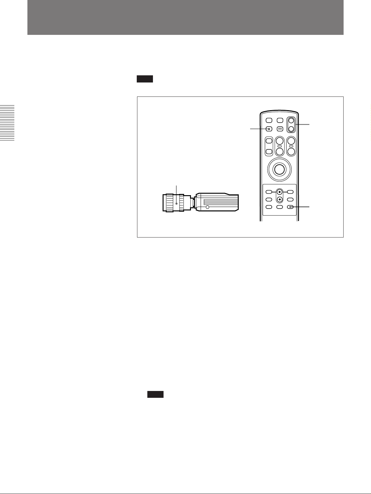
Adjusting the Iris
Use the following procedure to adjust the iris setting (f-stop) at the instant
that a still image is captured to memory.
Note
For normal purposes select F5.60 (factory default setting).
Chapter 2 Operation
2
STDBY USER
LIVE/MEMORY E-ZOOM
MEMORY FOCUS ZOOM
+
--
FAR
NEAR
IRIS
+
--
T
W
4
1
MENU ENTER
WB(STILL)
WB(LIVE)
FRAME
ON/OFF
CHARACTER
ON/OFF
BB
3
1 Set the lens to the automatic iris mode.
2 If in the memory monitor mode, press the LIVE/MEMORY button to
switch to the live mode.
The “LIVE” mode indication appears on the monitor screen.
3 If the status display mode is off, press the CHARACTER ON/OFF
button to switch on the status display.
The f-stop setting appears on the monitor screen.
4 • To increase the numerical value of the f-stop (i.e. to stop down the
iris for still image capture), press the IRIS + button.
•To decrease the numerical value of the f-stop (i.e. to open up the iris
for still image capture), press the IRIS – button.
Note
Changing this setting does not affect the iris during output of live
images. The f-stop setting only takes effect when the release button is
next pressed.
30 Chapter 2 Operation
Page 31
Using the AE Function
You can use the AE (Auto Exposure) function to automatically adjust the
brightness level of still images. The following three AE modes are available
• aperture priority
• shutter priority, and
• program.
his section describes how to use these three AE modes. It also describes the
T
AE compensation function to finely adjust the AE-adjusted brightness level
Note
When using the AE function, it is necessary to set the FLASH item to
“OFF” in the FLASH menu.
For details of menu operations, see Chapter 4.
Using the aperture priority AE mode
The aperture priority AE mode automatically adjusts the shutter speed to
an iris (f-stop) setting made by the user so that the optimal brightness level
is obtained.
:
.
Chapter 2 Operation
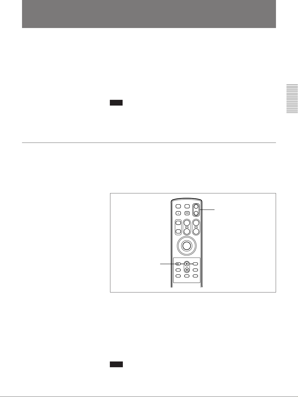
To set the AE function to aperture priority mode, use the following procedure.
1
STDBY USER
LIVE/MEMORY E-ZOOM
MEMORY FOCUS ZOOM
+
--
MENU ENTER
WB(STILL)
WB(LIVE)
NEAR
IRIS
+
--
FAR
T
W
FRAME
ON/OFF
CHARACTER
ON/OFF
BB
2
1 Press the MENU button on the remote controller to access the main
menu. Select the CAMERA menu from the main menu, and set “AE
MODE” to “APERTURE.”
For details of menu operations, see Chapter 4.
2 Press the IRIS +/– buttons to adjust the iris.
For details of the adjustment, see page 30.
Note
Setting the AE function to aperture priority mode disables the
“SHUTTER” item of the CAMERA menu.
Chapter 2 Operation 31
Page 32
Using the AE Function
Using the shutter priority AE mode
Chapter 2 Operation
The shutter priority AE mode automatically adjusts the iris to a shutter
speed set by the user so that the optimal brightness level is obtained.
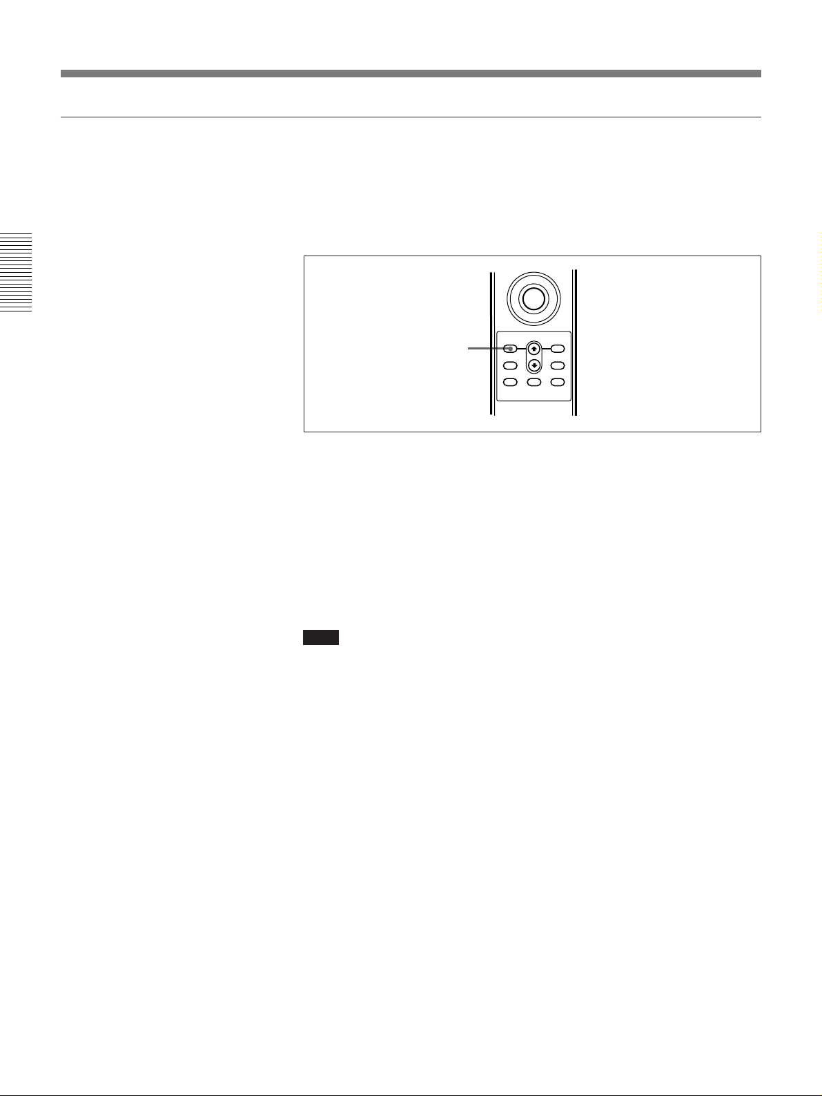
To set the AE function to shutter priority mode, use the following
procedure.
1
MENU ENTER
WB(STILL)
WB(LIVE)
BB
FRAME
ON/OFF
CHARACTER
ON/OFF
1 Press the MENU button on the remote controller to access the main
menu, and select the CAMERA menu.
For details of menu operations, see Chapter 4.
2 In the CAMERA menu set “AE MODE” to “SHUTTER”, then exit the
menu system.
The f-stop indication in the monitor screen changes to “AE-S.”
Note
Setting the AE function to shutter priority mode disables the remote
controller’s IRIS +/– buttons.
32 Chapter 2 Operation
Page 33
Using the program AE mode
The program AE mode automatically opens the iris fully and adjusts the
shutter speed and ISO exposure so that the optimal brightness level is
obtained.
To set the AE function to program mode, use the following procedure.
Chapter 2 Operation
1
MENU ENTER
WB(STILL)
WB(LIVE)
BB
FRAME
ON/OFF
CHARACTER
ON/OFF
1 Press the MENU button on the remote controller to access the main
menu, and select the CAMERA menu.
For details of menu operations, see Chapter 4.
2 In the CAMERA menu set “AE MODE” to “PROGRAM,” then exit
the menu system.
The f-stop indication in the monitor screen changes to “AE-P.”
Note
Setting the AE function to program mode disables:
• the “SHUTTER” and “ISO” items of the CAMERA menu
• the remote controller’s STDBY button when a lens other than the VCL1205BYS is used
• the remote controller’s IRIS +/– buttons.
Chapter 2 Operation 33
Page 34
Using the AE Function
Using the AE compensation function
Chapter 2 Operation
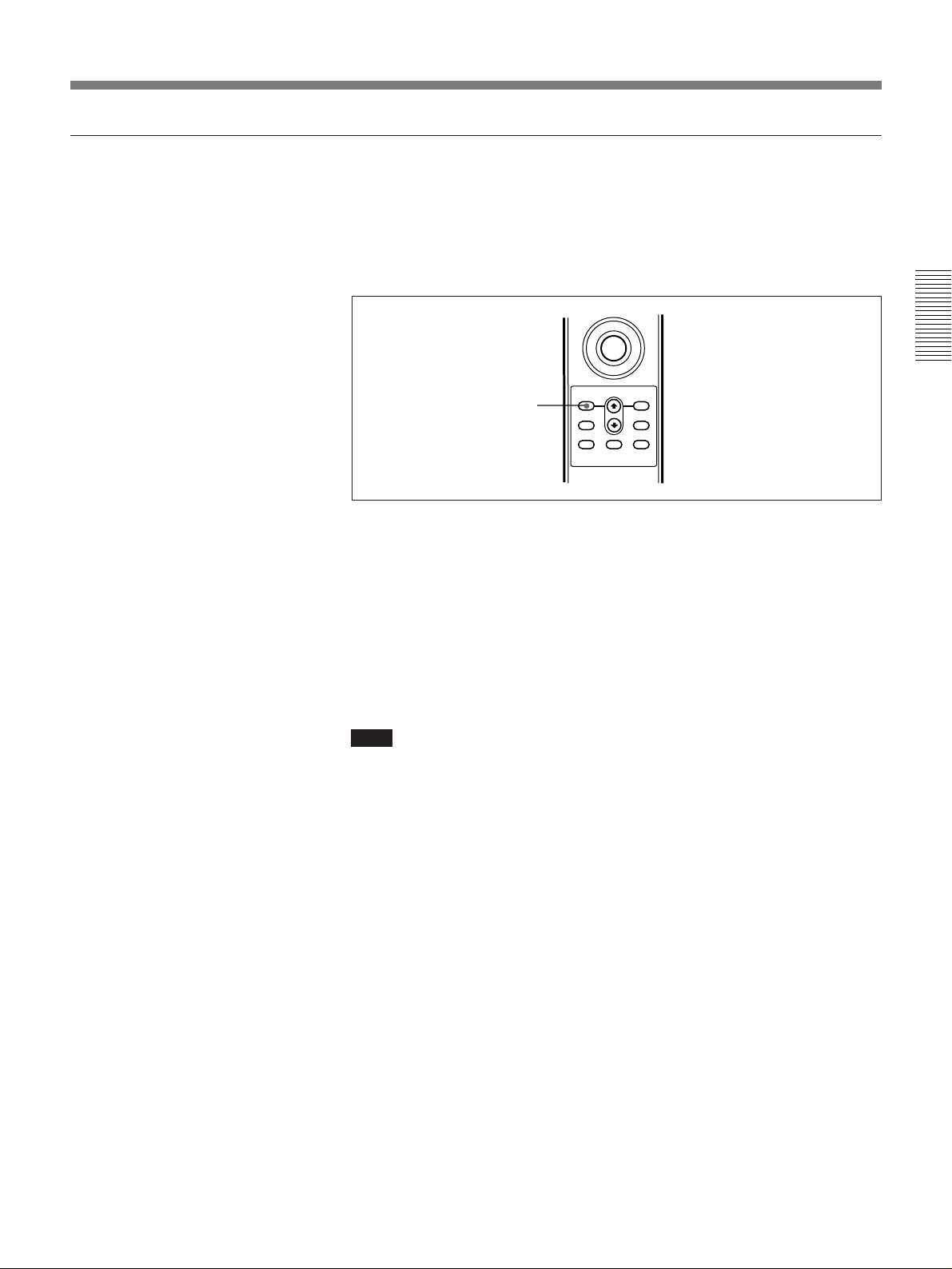
The AE compensation function allows you to finely adjust the brightness
level that should result from activation of the AE function in any of the
three modes described above.
To make an AE compensation setting, use the following procedure.
1
MENU ENTER
WB(STILL)
WB(LIVE)
FRAME
ON/OFF
CHARACTER
ON/OFF
BB
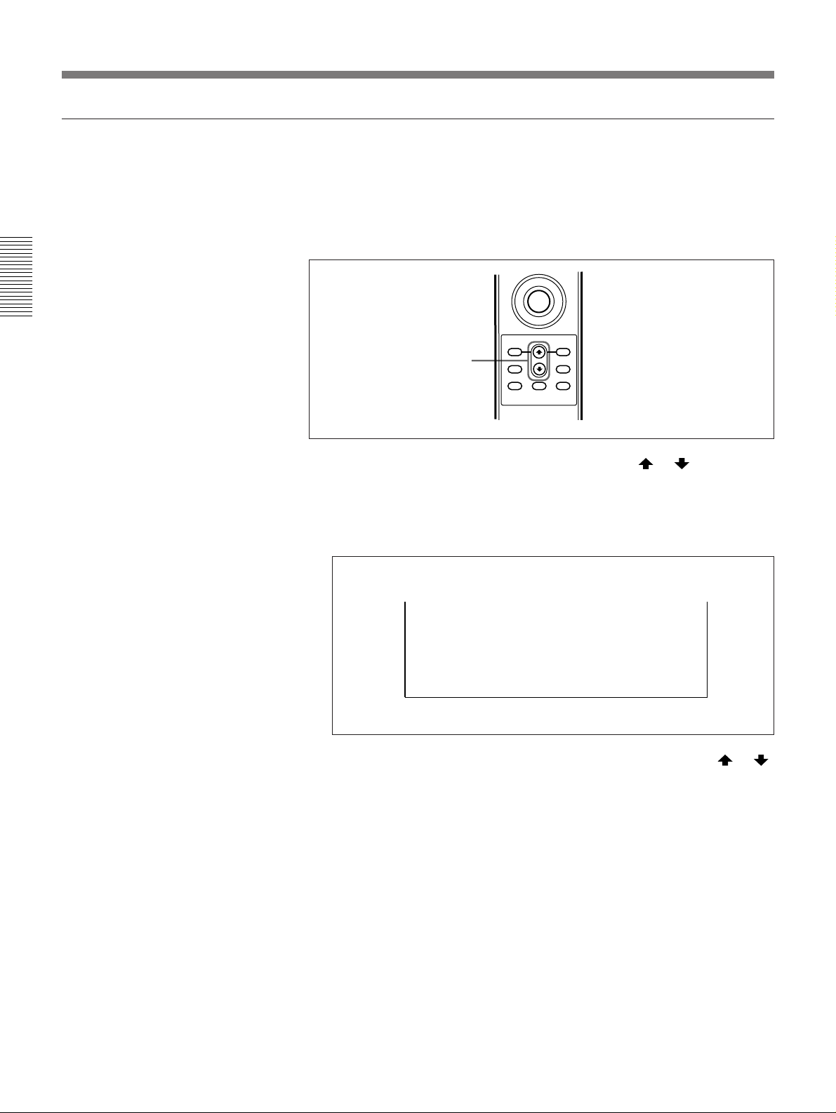
1 When the menu system is not accessed, press the or button on
the remote controller.
At the bottom of the monitor screen appears the indication “AE-CMP,”
followed by the currently set AE compensation value.
AE-CMP: 0
+
–
2 To increase or decrease the AE compensation value, press the or
button on the remote controller. (The setting range is –9 to +9.)
34 Chapter 2 Operation
Page 35
3
4
1
STDBY USER
LIVE/MEMORY E-ZOOM
IRIS
MEMORY FOCUS ZOOM
FAR
NEAR
T
W
+
--
+
--
MENU ENTER
WB(STILL)
WB(LIVE)
BB
FRAME
ON/OFF
CHARACTER
ON/OFF
Shooting
Basic Procedure
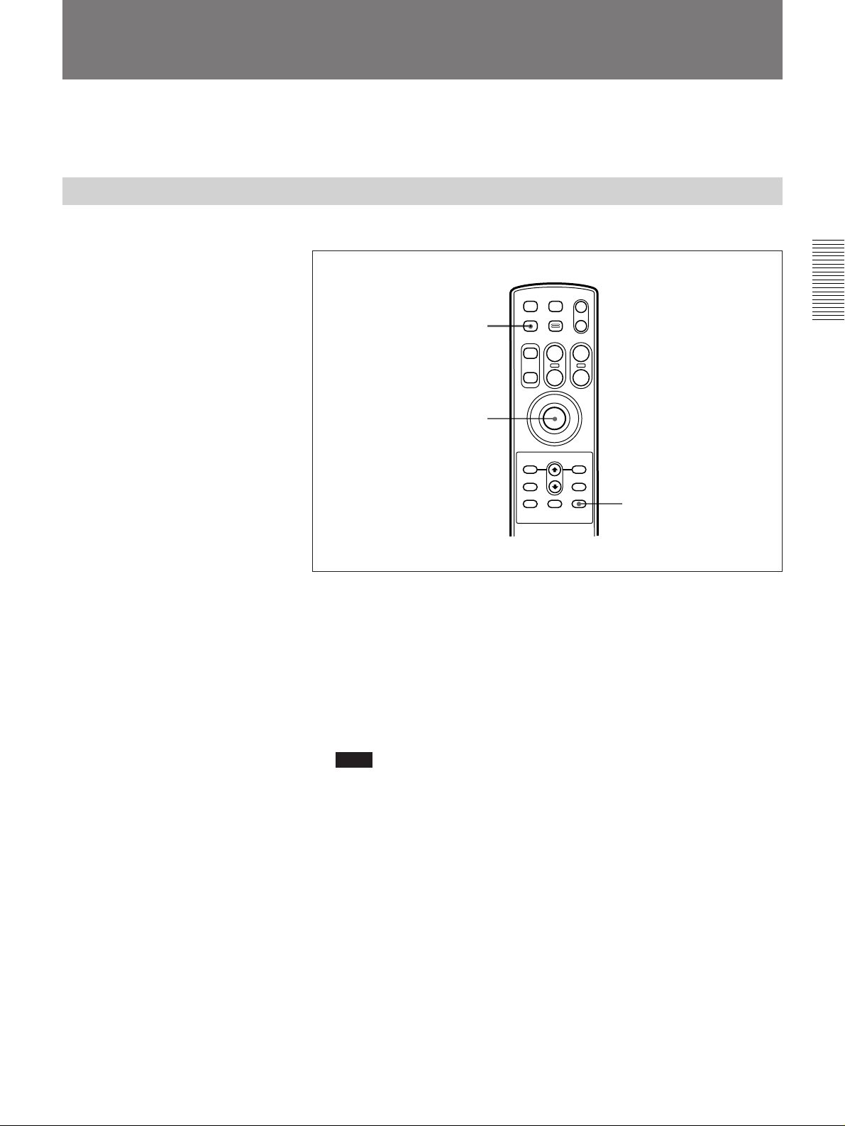
This section describes the procedures for selecting image memories and
for shooting (capturing an image into the selected memory).
The following is the basic procedure for shooting.
Chapter 2 Operation
1 If the status display mode is off, press the CHARACTER ON/OFF
button to switch on the status display, and check the memory status
indication (selection and availability).
2 Select the memory into which you wish to capture an image.
For details, see the section “Selecting a Memory” on page 37.
Note
If you select a memory which already holds an image, carrying out
step 4 will overwrite this existing image in the memory.
3 If in the memory monitor mode, press the LIVE/MEMORY button to
switch to the live monitor mode.
The “LIVE” mode indication appears on the monitor screen.
(Continued)
Chapter 2 Operation 35
Page 36

Chapter 2 Operation
Shooting
4 Press the release button.
This instantaneously stops the lens down to the iris setting, and
captures an image to the selected memory.
Note
When using a lens other than the special-purpose lens
(VCL-1205BYS), press the STDBY button first, to switch to the
standby mode, then press the release button.
When you switch to standby mode, after about 3 seconds the iris is
stopped down to the current setting, and the “STAND-BY” mode
indication appears on the monitor screen.
•When the memory selection mode is “increment on,” first the system
switches to review mode, and the image captured to memory appears
on the monitor for a few seconds.
Next the system switches back to live monitor mode. During the
review, the “REVIEW” mode indication appears on the monitor
screen.
•When the memory selection mode is “increment off,” the system
switches to memory monitor mode, and the image captured to
memory is displayed on the monitor screen.
For details of the memory selection mode, see the section “Selecting a
Memory” on the next page.
5 To continue shooting, repeat steps 2 to 4.
36 Chapter 2 Operation
Page 37
Selecting a Memory
“Increment on” mode
There are two modes in which you can select a memory: “increment on”
mode, and “increment off” mode.
In “increment on” mode, each time you press the release button to capture
an image in memory, the memory selection for the next image is
incremented automatically (1, 2, 3, ... 9).
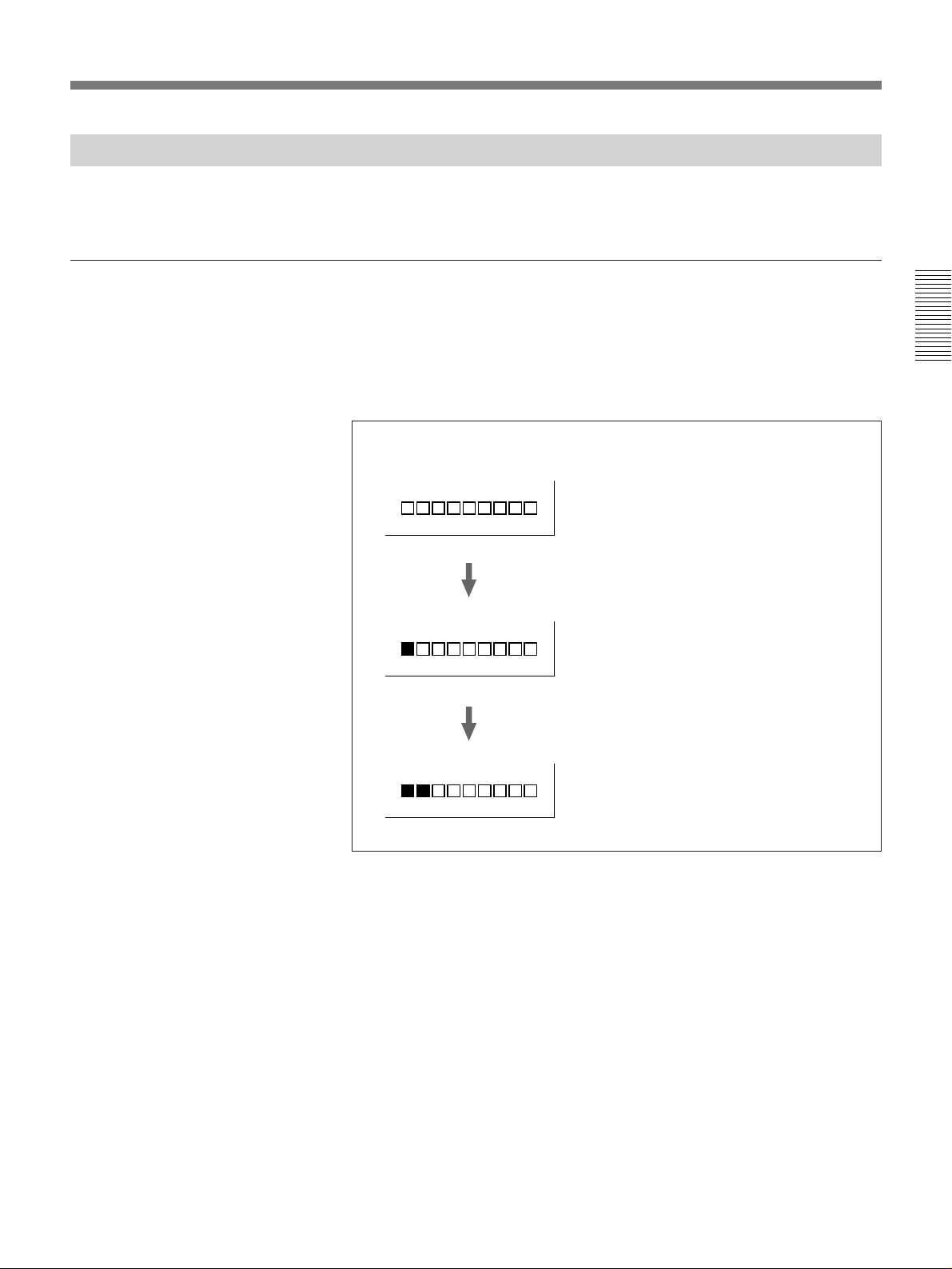
The following shows how the memory selection changes in “increment
on” mode.
Memory status indication
When using the system initially, memory 1 is
selected for image capture. (The white
squares indicate that the memories do not hold
1
images.)
Press release button...
Chapter 2 Operation
An image is captured in memory 1, and after a
transient review, the system returns to the live
1
2
monitor mode. (The film icon indicates a
memory which holds an image.)
Press release button again...
An image is captured in memory 2, and after a
transient review, the system again returns to the
live monitor mode. Pressing the release button
once again will capture an image to memory 3.
To select the “increment on” mode
From the main menu, select the CAMERA menu, then set the
“INCREMENT” item to “ON” (this is the factory default setting).
For details of menu operations, see Chapter 4.
Chapter 2 Operation 37
Page 38

Chapter 2 Operation
Shooting
“Loop on” mode and “loop off” mode
In “increment on” mode, there are two ways of operating: either the “loop
on” mode or the “loop off” mode.
“Loop on” mode: After an image is captured to memory 9, memory 1 is
automatically selected for the next image.
Note
If there is already an image stored in memory 1 (i.e. the status
indication shows a film icon for memory 1), when you press the
release button this captures a new image to memory 1, and the
previously stored image is lost.
“Loop off” mode: After an image is captured to memory 9, there is no
automatic memory selection, and after the review, the system returns
to the live monitor mode with a message “MEMORY FULL” display.
To switch between “loop on” mode and “loop off” mode
From the main menu, select the CAMERA menu, then set the “LOOP”
item to “ON” (this is the factory default setting) or “OFF.”
38 Chapter 2 Operation
Page 39
“Increment off” mode
In “increment off” mode, when you press the release button there is no
automatic memory selection. To select the memory, enter memory
monitor mode, then press the MEMORY +/– buttons.
To select memory numbers in ascending order press the MEMORY +
button, and to select memory numbers in descending order press the
MEMORY – button.
Note
The MEMORY +/– buttons do not operate in the live monitor mode. First
press the LIVE/MEMORY button to switch to memory monitor mode.
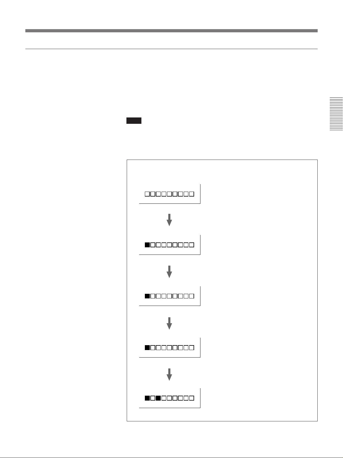
The following shows an example of operation in “increment off” mode.
Memory status indication
When using the system initially, memory 1 is
selected for image capture.
1
Switch to live monitor mode and press release
button...
Chapter 2 Operation
An image is captured in memory 1, and the
system automatically switches to memory monitor
1
1
3
3
mode. Memory 1 remains selected.
Switch to live monitor mode and press release
button...
A new image overwrites the existing image in
memory 1, and the system switches to memory
monitor mode. Memory 1 remains selected. To
select memory 3 for the next image...
Press MEMORY + button twice.
Memory 3 is selected.
Switch to live monitor mode and press release
button...
An image is captured in memory 3, and the
system switches to memory monitor mode.
Memory 3 remains selected.
Chapter 2 Operation 39
Page 40

Chapter 2 Operation
Shooting
To select the “increment off” mode
From the main menu, select the CAMERA menu, then set the
“INCREMENT” item to “OFF.”
For details of menu operations, see Chapter 4.
40 Chapter 2 Operation
Page 41
Manually selecting a memory while in “increment on” mode
Even in “increment on” mode, you can use the MEMORY +/– buttons to
select a memory.
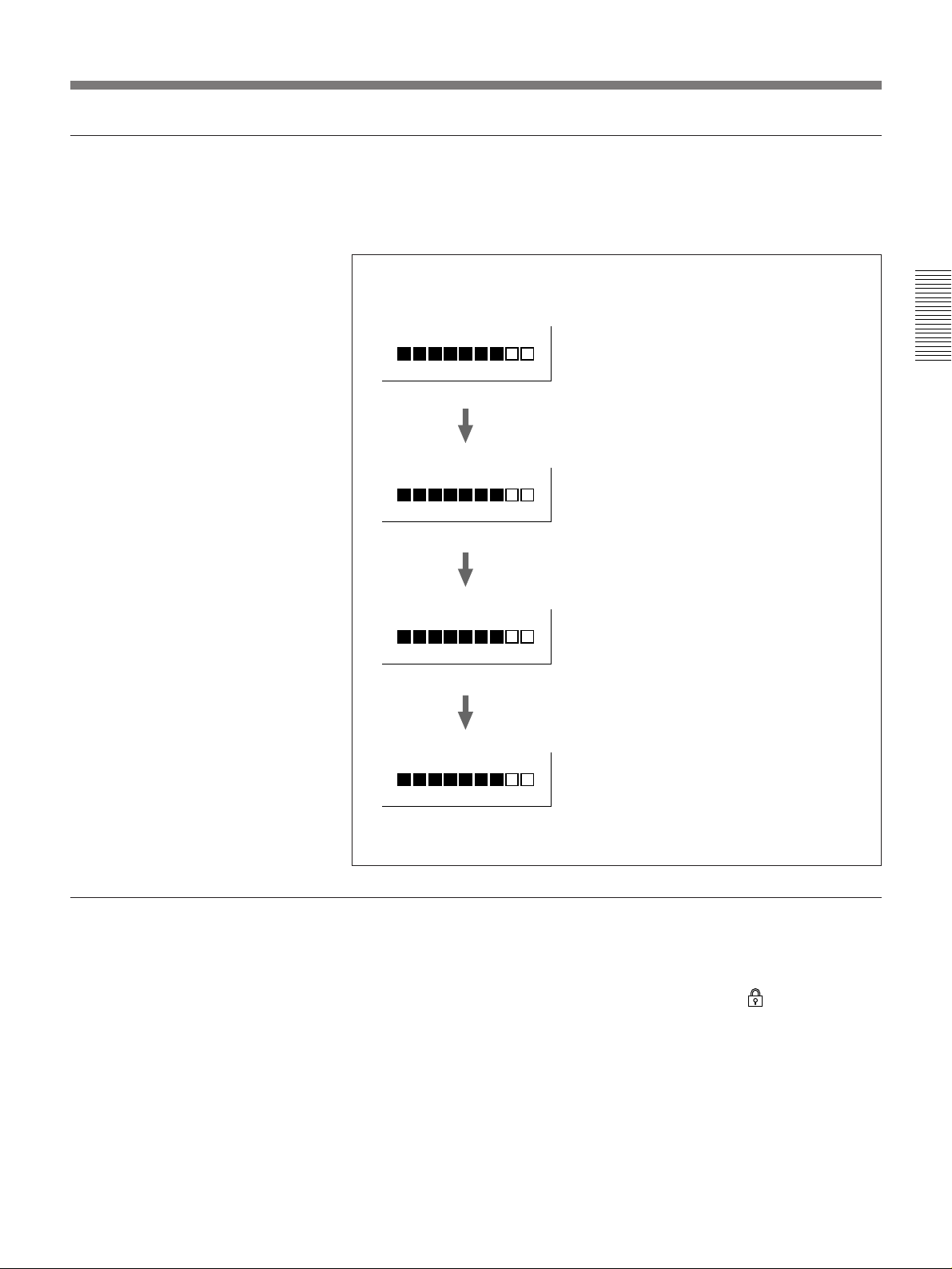
The following shows an example of such operation.
Memory status indication
In “increment on” mode, pressing the release
button in this state will capture an image in
7
3
memory 8. To change this, and select memory 3
for the next image...
Switch to memory monitor mode and press
MEMORY – button four times.
Memory 3 is selected.
Switch to live monitor mode and press release
button...
Chapter 2 Operation
Preventing overwriting of memory
By control from the computer, you can lock any particular memory so that
it cannot be overwritten.
When a memory is locked in this way (status indication
selection basically proceeds in the same way as before, except that any
locked memories are skipped. In other words, if only memory 4 is locked,
an image which would have been captured in memory 4 is in fact captured
in memory 5.
An image is captured in memory 3, and after a
transient review, the system returns to the live
3
4
monitor mode.
Press release button...
An image is captured in memory 4, and after a
transient review, the system returns to the live
monitor mode.
) the memory
Chapter 2 Operation 41
Page 42
Chapter 2 Operation
Shooting
Reviewing a Captured Image
In “increment on” mode
When the memory selection mode is set to “increment on,” pressing the
release button causes the system to automatically switch to review mode,
and display the captured image on the monitor screen for several seconds.
Thereafter it automatically returns to the live monitor mode. Thus you can
continue to capture images while quickly checking each one.
In “increment off” mode
In this mode, pressing the release button causes the system to switch to the
memory monitor mode, and display the captured image on the monitor
screen. The same image remains displayed until you select the live
monitor mode again.
Selecting memory monitor mode to check images
Whether in the “increment on” or “increment off” mode, you can check the
contents of any particular memory by using the following procedure.
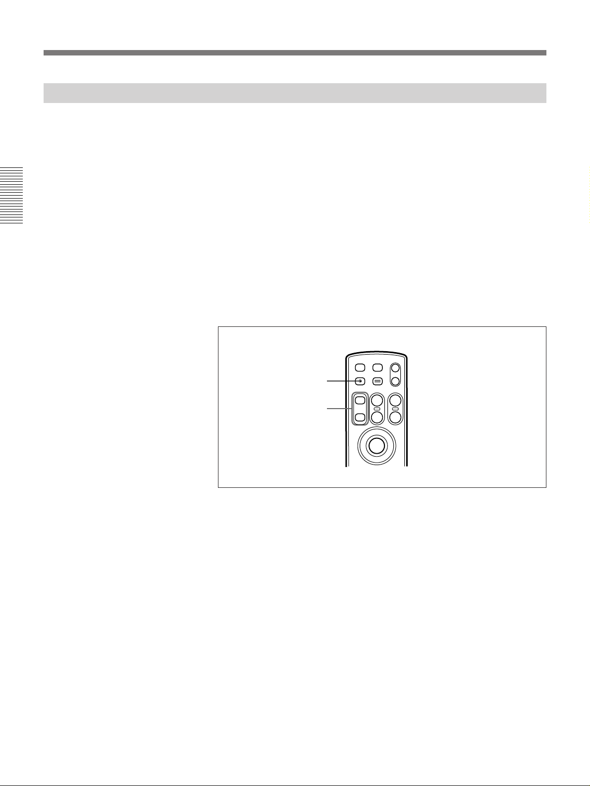
1
2
STDBY USER
LIVE/MEMORY E-ZOOM
MEMORY FOCUS ZOOM
+
--
NEAR
IRIS
+
--
FAR
T
W
1 If not in memory monitor mode, press the LIVE/MEMORY button to
switch to the memory monitor mode.
This displays the image held in the currently selected memory on the
monitor.
2 Press the MEMORY +/– buttons to select other memories to check.
This displays the image held in each selected memory on the monitor.
42 Chapter 2 Operation
Page 43

Switching Between Landscape and Portrait Orientations
You can turn the tripod mount through 90 degrees to alter the camera
orientation, for either portrait or landscape images.
Turn tripod
mount through
90 degrees
Portrait Landscape
Menu and status indications
When the camera head is in the landscape orientation, the display of menus
and status information on the monitor screen is also turned through 90
degrees.
To make these displays horizontal as in the portrait mode, from the main
menu select the CAMERA menu, and set the “ROTATE” item to “OFF.”
Chapter 2 Operation
For details of menu operations, see Chapter 4.
Notes
•It is recommended to use a portrait monitor when shooting in portrait
format and a landscape monitor when shooting in landscape format.
Physically rotating a monitor through 90 degrees may damage it or cause
it to fail.
•When using the camera head in the orientation shown below, select the
CAMERA menu from the main menu and set the “ROTATE” item to
“OFF.”
Chapter 2 Operation 43
Page 44

Page 45
Installing the Camera Head
Mounting the Camera Head on a Tripod
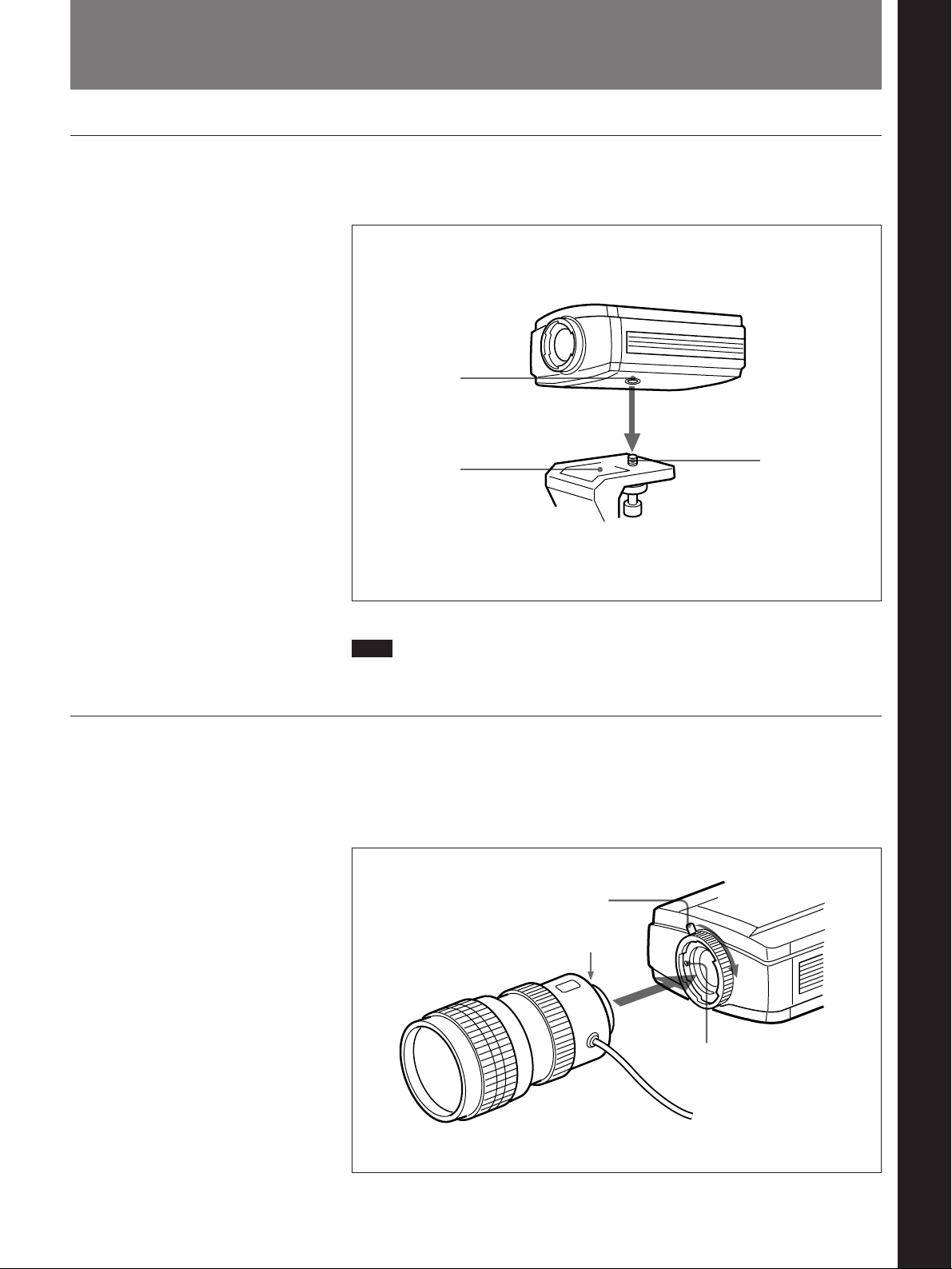
Align the threaded mounting hole on the bottom of the camera with the
fixing screw on the tripod mount, and tighten the fixing screw securely.
Mounting hole
Chapter 3 Installation and Connections
Mounting the Lens
Tripod mount
Note
Fixing screw
The tripod must be designed to support a load of at least 5 kg.
Insert the lens into the camera lens mount, then press down the lens
locking lever in a clockwise direction. Make sure that the lens is inserted
with the projection on the mounting end in alignment with the engaging
hole marked in red.
Lens locking lever
Chapter 3 Installation and Connections
Projection
Engaging hole
marked in red
Chapter 3 Installation and Connections 45
Page 46
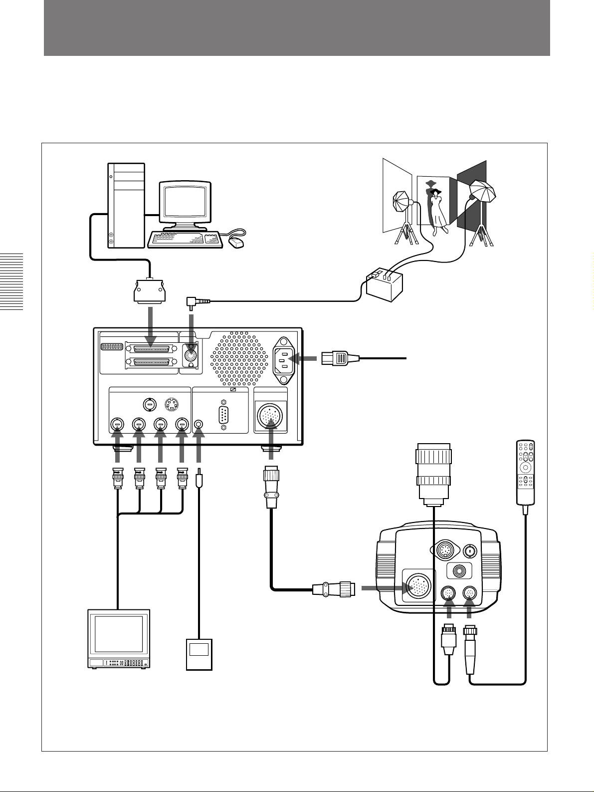
Connections
The connections required depend on the system components being used.
See the section “Principal Examples of Use” on page 9 to determine the required
devices.
Chapter 3 Installation and Connections
MODE SELECT SCSI In
Digital
processing
unit
Computer
SCSI cable
(not supplied)
To SCSI
connector
a)
SCSI FLASH
SCSI Out
MONITOR REMOTE CAMERA
VIDEO S-VIDEO
R G B SYNC
To FLASH connector
RS-232C
FS
Flash
Generator
AC IN
⁄
To AC IN connector
AC power cord
(supplied)
Lens
(VCL-1205BYS)
Remote
controller
To R/G/B/
SYNC
To FS
connector
To CAMERA connector
b)
connectors
75-ohm coaxial
cables
(not supplied)
Camera cable
(supplied)
Foot switch
Camera head
To PROCESSOR
connector
b)
PROCESSOR
To LENS1
connector
VF
LENS1
MONITOR
FLASH
REMOTE
To
REMOTE
connector
(FS-20)
Color video monitor
a) For details of SCSI connections see the next page.
b) Align the red mark on the connector on the end of the cable with the corresponding red mark on the CAMERA connector of the
processor and the PROCESSOR connector of the camera.
46 Chapter 3 Installation and Connections
Page 47
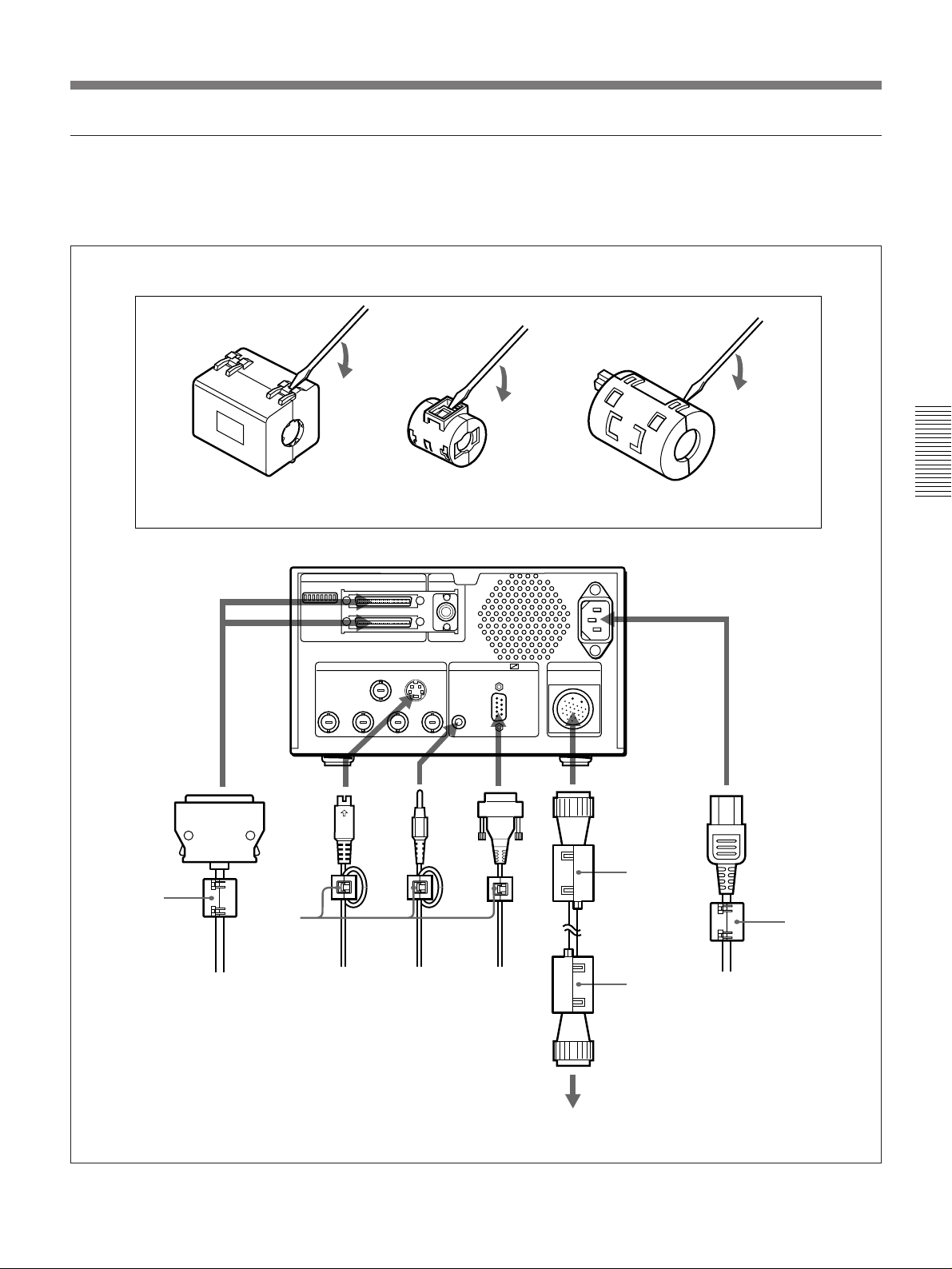
Attaching Ferrite Cores to Cables
To protect the digital processor against noise which may affect its
operation, attach supplied ferrite cores (noise filters) to some of the
connection cables as shown below.
How to open the ferrite cores
Use a screwdriver to
unlock the latches.
Type A
Type-A ferrite core
Type B
MODE SELECT
SCSI FLASH
SCSI In
SCSI Out
MONITOR REMOTE CAMERA
VIDEO S-VIDEO
R G B SYNC
Type-B ferrite core
RS-232C
FS
Type-C ferrite core (for PAL model only)
AC IN
⁄
Type C
Camera
c)
cable
Chapter 3 Installation and Connections
Type A
SCSI cable
S-video
cable
a)
Foot switch
cable
9-pin remote
b)
control cable
a)When placing the ferrite core on the cable, make one turn of cable
through the core.
b)To connect a foot switch cable to the PAL model of DKC-ST5, use a
Type-B ferrite core. When placing the ferrite core on the cable, make
one turn of cable through the core.
c) With the PAL model of DKC-ST5, place two Type-C ferrite cores on
the camera cable, one at the processor-side end of cable and the
other at the camera-side end.
To the camera
Type C
Power cord
Chapter 3 Installation and Connections 47
Page 48
SCSI Connections
SCSI Cables
Chapter 3 Installation and Connections
SCSI Terminators
This section describes the SCSI connections between the DKC-ST5 and a
computer and any other SCSI devices.
Note
Power off the DKC-ST5 and all of the other connected devices before
making the SCSI connections.
It is recommended to use high-impedance cables complying with the
SCSI-2 standard for the connections.
Note
Up to seven SCSI devices can be connected in a daisy-chain to the SCSI
port of the computer, but the total length of the SCSI cables should not
exceed 6 meters.
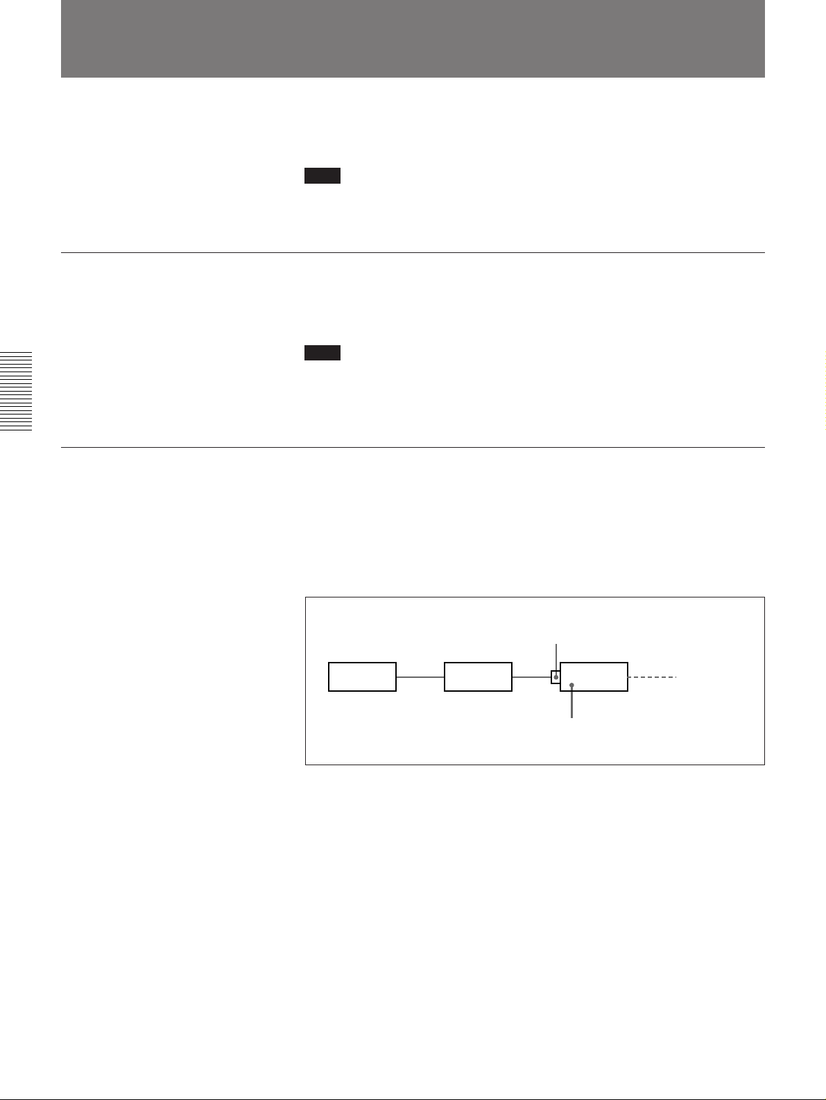
Using the DKC-ST5 internal terminator
The DKC-ST5 has a built-in active SCSI terminator. If you do not have an
external terminator, then as shown in the following illustration, connect the
DKC-ST5 as the last device in the chain, and enable the internal
terminator. (Set DIP switch 4 on the digital processor to the ON position;
see page 50.)
SCSI In connector
Computer UP-D8800 DKC-ST5 No connection
Enable internal
terminator
48 Chapter 3 Installation and Connections
Page 49
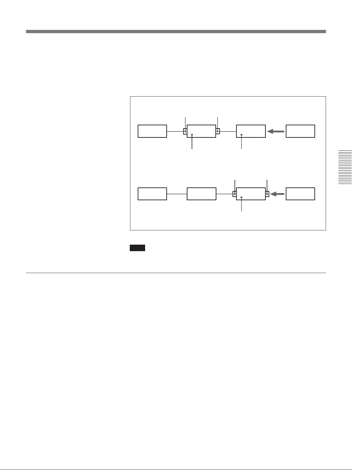
Not using the DKC-ST5 internal terminator
In this case, carry out the two following items:
•Disable the DKC-ST5 internal terminator. (Set DIP switch 4 on the
digital processor to the OFF position; see the next page.)
•Fit an external terminator to the last SCSI device in the chain. It is
recommended to use an active type of external terminator.
SCSI ID
SCSI In
connector
Computer
Disable internal
terminator
Computer
Note
SCSI Out
connector
DKC-ST5
SCSI In connector
UP-D8800 DKC-ST5
UP-D8800
Fit external terminator
to last SCSI device in
the chain.
Disable internal terminator and
fit external terminator.
Terminator
SCSI Out connector
Terminator
The number of operative terminators in a SCSI chain must always be two.
Chapter 3 Installation and Connections
When you connect a number of SCSI devices in a daisy-chain, it is
important to assign SCSI IDs (0 to 7) to the devices in such a way that they
do not conflict.
To set the SCSI ID of the DKC-ST5, use DIP switches 6 to 8 on the digital
processor.
For details of the settings of the DIP switches, see the next page.
Note that the allocation of IDs is not related to the physical sequence of the
devices in the chain.
Chapter 3 Installation and Connections 49
Page 50
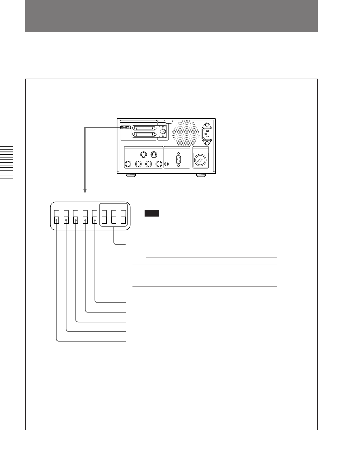
Setting the DIP Switches
Chapter 3 Installation and Connections
There are eight DIP switches on the rear panel of the digital processor.
When using the system for the first time, before powering on set these
switches appropriately.
The following shows the function of each of the DIP switches.
OFF
12345678ON
Note
Carry out the DIP switch setting operation with
the power of the system turned off.
Unit SCSI ID
Switch SCSI ID
01234567
8 OFF ON OFF ON OFF ON OFF ON
7 OFF OFF ON ON OFF OFF ON ON
6 OFF OFF OFF OFF ON ON ON ON
Unused (set to OFF)
SCSI active terminator
Unused (set to OFF)
Unused (set to OFF)
Camera cable
compensation
(ON: 25 m, OFF: 10 m)
50 Chapter 3 Installation and Connections
Page 51

Overview
Main menu
Live menu
Chapter 4 Menus
You use the menus to make various camera settings such as the color
temperature conversion characteristics, the electronic shutter speed, and so
forth.
There are two principal menus, the main menu, and the live menu.
All settings affecting still images (i.e. those captured into memory) are in
the main menu, which consists of a number of submenus.
For details of the settings in the main menu, see page 55.
To access the main menu
Press the MENU button.
The live menu contains only color balance settings for live images (i.e. the
camera output in live monitor mode).
For details of the settings in the live menu, see page 58.
To access the live menu
Hold down the MENU button for at least two seconds.
Chapter 4 Menus
Chapter 4 Menus 51
Page 52
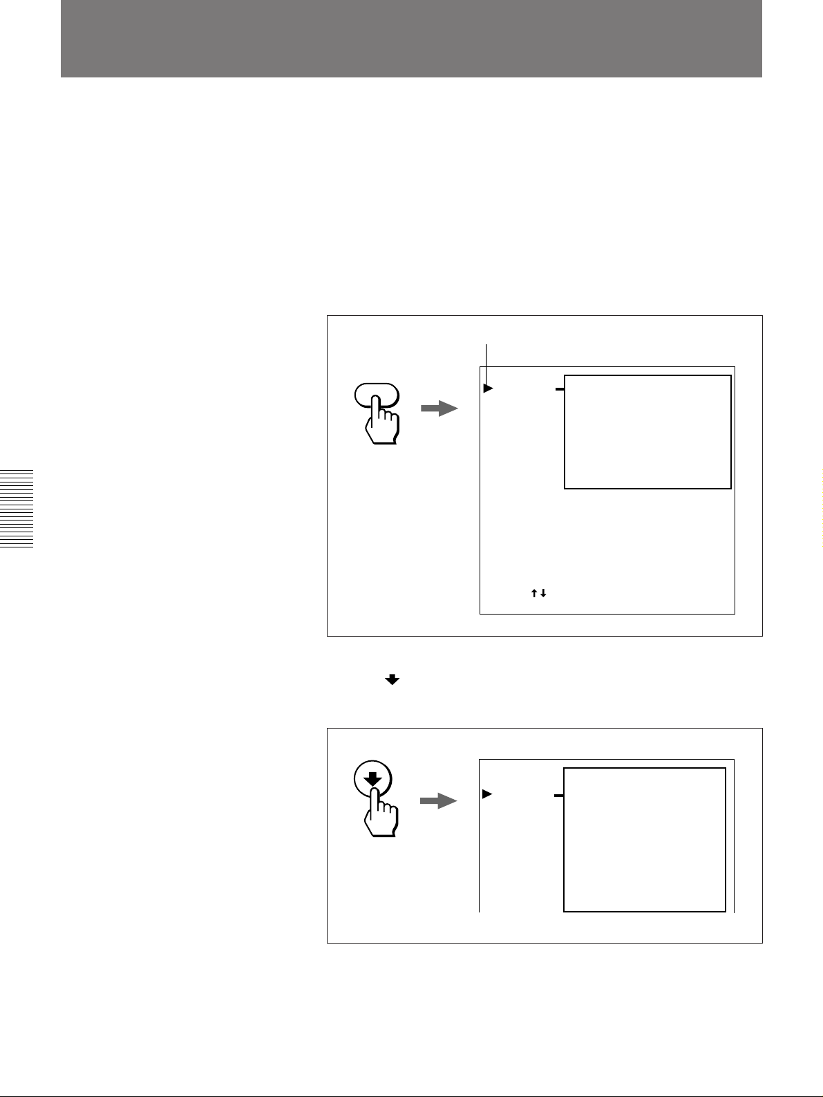
Basic Menu Operation Procedure
This section illustrates the basic menu operation procedure, taking as an
example the method of setting the ISO exposure index (the “film speed”).
Note that the procedure for accessing the live menu is exactly the same,
except that you must hold down the MENU button for at least two seconds.
Use the following procedure to set the ISO exposure index.
1 Press the MENU button.
The main menu appears on the monitor screen. When you access the
main menu initially, the cursor is by the PICTURE item.
Cursor
MENU
PICTURE
CAMERA
FLASH
OTHERS
C–TEMP:
.
RED:
.
BLUE:
CONTRAST:
SHARPNESS:
MASKING:
GAMMA:
AWB
0
0
0
LOW
LOW
STANDARD
Chapter 4 Menus
Press [ ] and [ENTER] Exit [MENU]
2 Press the button to align the cursor with “CAMERA.”
This selects the CAMERA menu, and the following items appear.
PICTURE
CAMERA
FLASH
OTHERS
SHUTTER:
EXPOSURE:
INCREMENT:
.
REVIEW TIME:
.
IRIS OPEN:
.
LOOP:
ROTATE:
AE MODE:
METERING:
1/125
ISO 20
ON
3 SEC
ON
ON
ON
MANUAL
PEAK
52 Chapter 4 Menus
Page 53
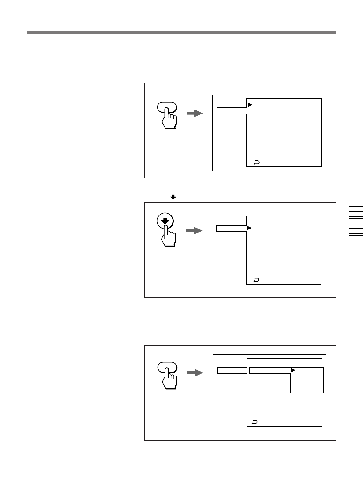
3 Press the ENTER button.
The cursor enters the CAMERA menu, and the extra “RETURN” item
appears in the bottom line.
ENTER
PICTURE
CAMERA
FLASH
OTHERS
SHUTTER:
EXPOSURE:
INCREMENT:
.
REVIEW TIME:
.
IRIS OPEN:
.
LOOP:
ROTATE:
AE MODE:
METERING:
RETURN
1/125
ISO 20
ON
3 SEC
ON
ON
ON
MANUAL
PEAK
4 Press the button to align the cursor with “EXPOSURE.”
PICTURE
CAMERA
FLASH
OTHERS
SHUTTER:
EXPOSURE:
INCREMENT:
.
REVIEW TIME:
.
IRIS OPEN:
.
LOOP:
ROTATE:
AE MODE:
METERING:
RETURN
5 Press the ENTER button.
This displays the setting list for the “EXPOSURE” item, with the
cursor pointing to the current setting.
ENTER
PICTURE
CAMERA
FLASH
OTHERS
SHUTTER:
EXPOSURE:
INCREMENT:
.
REVIEW TIME:
.
IRIS OPEN:
.
LOOP:
ROTATE:
AE MODE:
METERING:
RETURN
1/125
ISO 20
ON
3 SEC
ON
ON
ON
MANUAL
PEAK
1/125
ISO 20
ISO 40
ISO 80
ISO 160
ON
ON
MANUAL
PEAK
Chapter 4 Menus
(Continued)
Chapter 4 Menus 53
Page 54
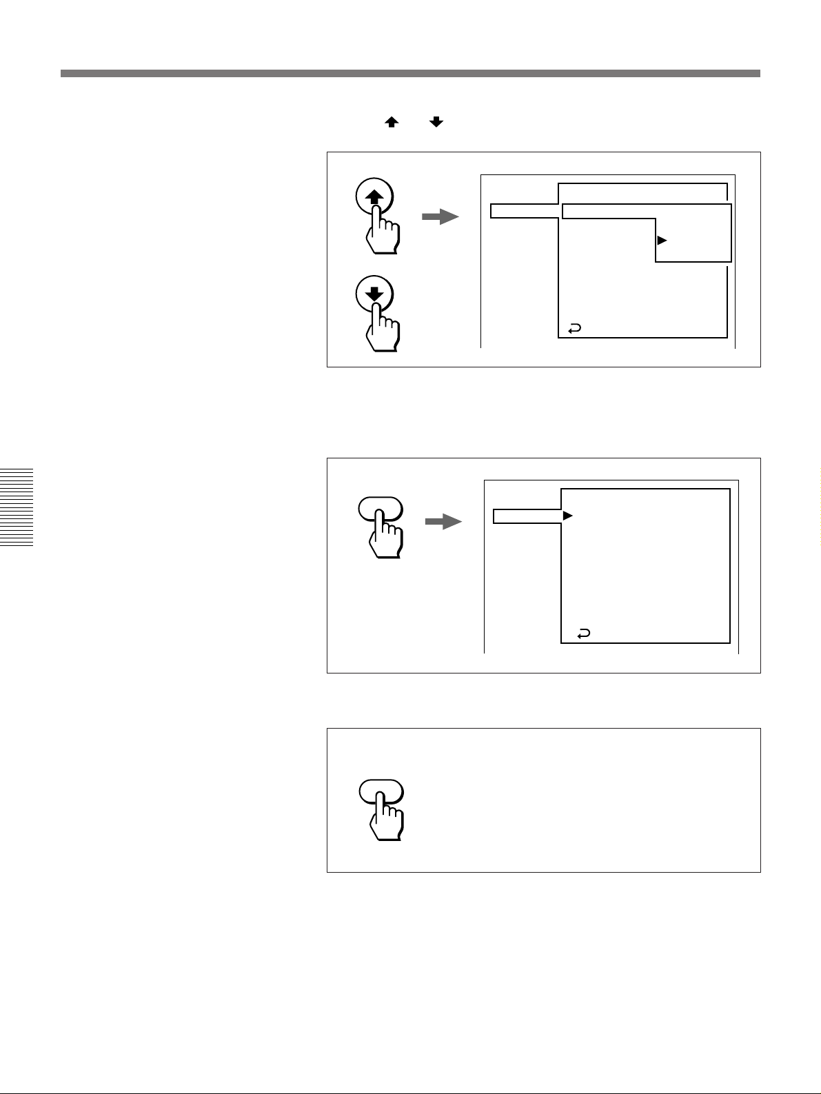
Basic Menu Procedure
6 Press the and buttons to move the cursor to the desired new
setting.
Chapter 4 Menus
PICTURE
CAMERA
FLASH
OTHERS
7 Press the ENTER button.
This updates the setting for “EXPOSURE.”
ENTER
PICTURE
CAMERA
FLASH
OTHERS
SHUTTER:
EXPOSURE:
INCREMENT:
.
REVIEW TIME:
.
IRIS OPEN:
.
LOOP:
ROTATE:
AE MODE:
METERING:
RETURN
SHUTTER:
EXPOSURE:
INCREMENT:
.
REVIEW TIME:
.
IRIS OPEN:
.
LOOP:
ROTATE:
AE MODE:
METERING:
RETURN
1/125
ISO 20
ISO 40
ISO 80
ISO 160
ON
ON
MANUAL
PEAK
1/125
ISO 80
ON
3 SEC
ON
ON
ON
MANUAL
PEAK
54 Chapter 4 Menus
8 To exit from the menus, press the MENU button.
MENU
The main menu disappears from the monitor screen.
Page 55

Menu Settings
Main Menu
PICTURE menu
The main menu consists of the following submenus:
•PICTURE menu
•CAMERA menu
•FLASH menu
•OTHERS menu
The following tables list the settings in each submenu.
Menu item
C-TEMP
Set the color temperature conversion characteristics of the
camera to match the light source being used.
•RED
Adjust the red gain. (After a white balance adjustment, it
is not normally necessary to set this item.)
•BLUE
Adjust the blue gain. (After a white balance adjustment, it
is not normally necessary to set this item.)
CONTRAST
Adjust the contrast.
SHARPNESS
Adjust the degree of outline emphasis (low, middle, or
high).
MASKING
Adjust the degree of increasing the color saturation (low,
medium, and high).
GAMMA
Adjust the gamma correction setting.
Settings
AWB: Automatically select the color balance setting taken for
still images.
5600K: Use this setting for daylight or fluorescent lighting.
3200K: Use this setting for tungsten lighting.
Factory default setting: AWB
–127 to +127
Factory default setting: 0
–127 to +127
Factory default setting: 0
Chapter 4 Menus
–5 to +5
Factory default setting: 0
OFF: No outline emphasis
LOW, MIDDLE, HIGH
Factory default setting: LOW
OFF: No increase in the color saturation.
LOW, MIDDLE, HIGH
Factory default setting: LOW
STANDARD: Use the standard setting.
PRESET1, PRESET2, PRESET3: Use the respective
PRESET1, PRESET2, and PRESET3 settings.
Factory default setting: STANDARD
Chapter 4 Menus 55
Page 56

Menu Settings
CAMERA menu
Chapter 4 Menus
Menu item
SHUTTER
Set the camera shutter speed (in seconds)
EXPOSURE
Set the ISO exposure index for the camera
INCREMENT
Select whether the memory selection is incremented
automatically or not.
For details of the method of memory selection, see page
37.
•REVIEW TIME
When the above “INCREMENT” item is set to “ON,”
adjust the review time, during which an image captured to
memory is displayed after the release button is pressed.
•IRIS OPEN
When the above “INCREMENT” item is set to “ON,”
select whether after the release button is pressed to
return to the live monitor mode, or not (i.e. to return the
lens iris to the fully open position)
•LOOP
When the above “INCREMENT” item is set to “ON,”
select whether or not to use the memory loop mode.
For details, see page 38.
ROTATE
Select whether or not to rotate the menu and status
displays on the monitor screen through 90 degrees.
AE MODE
Select the manual or automatic exposure mode.
METERING
Select the exposure metering method in the live monitor
mode.
Settings
4, 2, 1, 1/2, 1/3, 1/4, 1/6, 1/12, 1/25, 1/50, 1/60, 1/125, 1/250,
1/500, 1/1000, 1/2000, 1/5000, 1/10000
Factory default setting: 1/125
ISO 20, 40, 80, 160
Factory default setting: ISO 20
ON: The memory selection is incremented automatically.
When this setting is selected, the menu items “•REVIEW
TIME”, “•IRIS OPEN”, and “•LOOP” appear.
OFF: The memory selection is not incremented automatically.
Factory default setting: ON
0 sec, 1 sec, 3 sec, 5 sec, 10 sec
Factory default setting: 3 sec
ON: Return to the live monitor mode. Use this setting when
you wish to check each new image on the monitor screen.
OFF: Do not return to the live monitor mode (keep the iris
setting unchanged). Use this setting when the timing of
image capture is important.
Factory default setting: ON
ON: Select the memory loop mode. After capturing an image
to memory 9, memory 1 is automatically selected for the
next image.
OFF: Do not select the memory loop mode. After capturing an
image to memory 9, the message “MEMORY FULL”
appears.
Factory default setting: ON
ON: Rotate the displays through 90 degrees. Use this setting
to make it easier to check the displays in portrait format.
OFF: Do not rotate the displays through 90 degrees. Use this
setting to make it easier to check the displays in landscape
format.
Factory default setting: ON
MANUAL: Manual adjustment
APERTURE: Aperture priority automatic exposure
SHUTTER: Shutter priority automatic exposure
PROGRAM: Program automatic exposure
Factory default setting: MANUAL
PEAK: Adjust exposure to the maximum intensity “cell of
image” as defined by dividing the whole image into nine
cells having the same area. (The illustration below shows
a case in which the maximum intensity cell is the central
cell.) With this setting the surroundings of highlights may
become dark.
56 Chapter 4 Menus
Maximum intensity
“cell of image”
AVG: Adjust exposure to the average intensity of the image.
With this setting there may be “burn-out” in the highlights.
Factory default setting: PEAK
Page 57
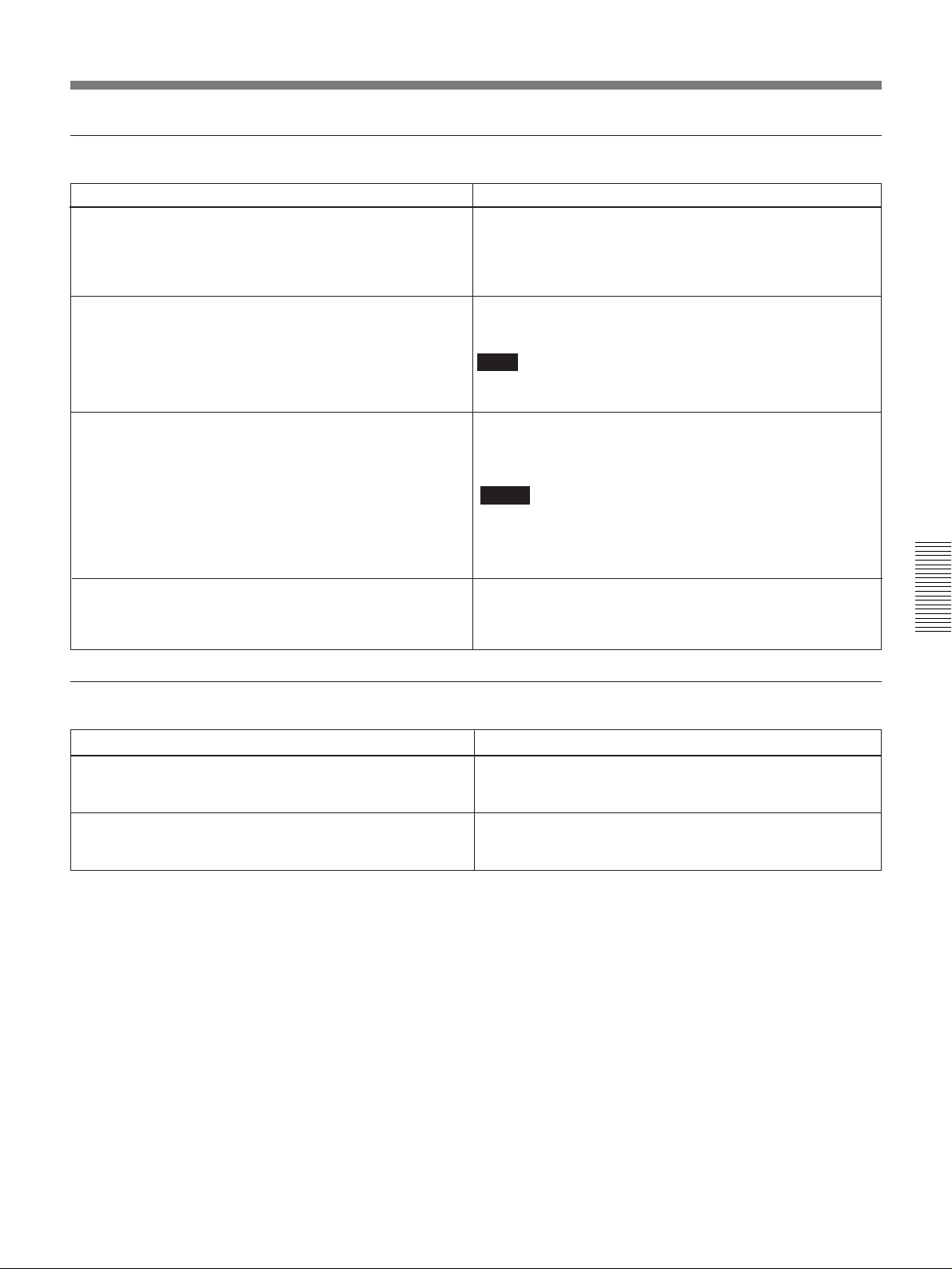
FLASH menu
Menu item
FLASH
Select whether or not to use the flash.
•INTERVAL
When the above “FLASH” item is set to “ON,” select the
flash operation interval.
•CUTOFF SW
When the above “FLASH” item is set to “ON,” select
whether or not to carry out mechanical control of the Xcontacts on the FLASH connector of the digital processor.
•CALIBRATION
When the above “FLASH” item is set to “ON,” measure
the synchronized timing of the flash and the electronic
shutter.
Settings
ON: Use the flash. When this setting is selected, the menu
items “•INTERVAL”, “•CUTOFF SW”, and
“•CALIBRATION” appear.
OFF: Do not use the flash.
Factory default setting: ON
1 sec, 3 sec, 5 sec, 10 sec
Factory default setting: 3 sec
Note
If the setting is less than the charge time for the flash used,
correct automatic control will not be possible.
ON: Carry out mechanical control.
OFF: Do not carry out mechanical control.
Factory default setting: OFF
Notes
• Normally use the camera with this item set to OFF. Only try
the ON setting if the flash will not work.
• Even when set to “ON,” there is no mechanical control of the
X-contacts on the camera.
START: Carry out the measurement.
CANCEL: Do not carry out the measurement.
Chapter 4 Menus
OTHERS menu
Menu item
BEEP
Select whether or not to beep for confirming an operation.
RESET
Reset all of the user menu settings to their factory
defaults.
Settings
ON: Beep.
OFF: Do not beep.
Factory default setting: ON
START: Carry out the reset.
CANCEL: Do not carry out the reset.
Chapter 4 Menus 57
Page 58
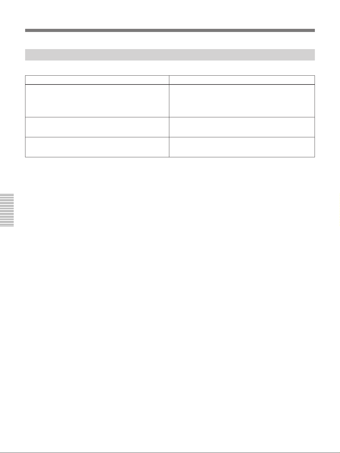
Menu Settings
Live Menu
The live menu consists of the following settings.
Menu item
C-TEMP
Set the color temperature conversion characteristics of
the camera to match the light source being used.
•RED
Adjust the red gain. (After a white balance adjustment, it
is not normally necessary to set this item.)
•BLUE
Adjust the blue gain. (After a white balance adjustment, it
is not normally necessary to set this item.)
Settings
AWB: Automatically select the color balance setting taken for
live images.
5600K: Use this setting for daylight or fluorescent lighting.
3200K: Use this setting for tungsten lighting.
Factory default setting: AWB
–127 to +127
Factory default setting: 0
–127 to +127
Factory default setting: 0
Chapter 4 Menus
58 Chapter 4 Menus
Page 59

Overview
Chapter 5 Using the Control Software
The floppy disks supplied with the DKC-ST5 contain
control software which runs under Microsoft Windows
1)
95/98
or on the Power Macintosh2) computer and is
designed for the following purposes:
•Capturing image data from the DKC-ST5 into the
computer
•Carrying out settings and basic operations on the
DKC-ST5 from the computer
Chapter 5 describes the environment required for
running the control software and the procedure for
installation, and also some notes on SCSI connections.
Background information
The following explanation assumes the reader is
familiar with basic computer terminology, and has
read the introductory documentation relating to
Microsoft Windows 95/98 (Microsoft Windows User’s
Guide and so forth) or Power Macintosh (Power
Macintosh User’s Manual and so forth).
Notes
•The control software may not run correctly using the
Microsoft Windows 95 built-in SCSI host adapter
5)
device driver and ASPI
32 manager.
•Be sure to install the device driver and ASPI32
manager stored on the miniport driver disk for
Microsoft Windows 95 shipped with the host adapter.
After installation, in the System folder within the
directory for Windows, the following file should be
present:
ASPI32 manager (wnaspi32.dll)
Also in the iosubsys folder beneath this should be the
following:
Device driver for the SCSI host adapter
(sparrow.mpd/ahal54x.mpd/aic78xx.mpd)
Check that these files are dated no earlier than
November 1, 1995.
•If your host adapter was not shipped with a miniport
driver disk for Microsoft Windows 95, install a new
5)
driver from Adaptec’s EZ-SCSI
4.x or 5.0 for
Microsoft Windows 95.
When using Power Macintosh
Required Hardware
• CPU: Power Macintosh (PPC Native)
• RAM capacity: at least 256 MB
• Monitor: 24-bit full-color display function
When using Microsoft Windows 95/98
• Free disk space: at least 150 MB
Computer
3)
An IBM PC/AT
or compatible computer with the
Required Software
following specification is required:
•CPU: Intel Pentium, MMX Pentium, Pentium Pro, or
Pentium II
4)
•RAM capacity: at least 32 MB
•Monitor: 24-bit full-color display function
When using an IBM PC/AT or compatible
computer
The Microsoft Windows 95/98 operating system is
required.
•Free disk space: at least 150 MB
When using a Power Macintosh computer
SCSI Host Adapter with Windows 95/98
Support
Version 7.5.5 or later of the Macintosh operating
system is required.
One of the Adaptec host adapters with Windows 95/98
support is required.
......................................................................................................................................................................................
1) Microsoft and Windows are registered trademarks of
Microsoft Corporation.
2) Power Macintosh is a registered trademark of Apple
Computer Inc.
3) IBM and AT are registered trademarks of International
Business Machines Corporation.
4) Pentium, MMX Pentium, Pentium Pro, and Pentium II
are registered trademarks of Intel Corporation.
5) ASPI and EZ-SCSI are registered trademarks of Adaptec
Inc.
Chapter 5 Using the Control Software
Chapter 5 Using the Control Software 59
Page 60

Installing the Control Software
Preparations
Checking the SCSI Host Adapter
(When using Microsoft Windows 95/98)
Use the following procedure to check that the Adaptec
SCSI host adapter is correctly installed.
1 Start Microsoft Windows 95/98.
2 Open the Control Panel window, and double-click
the System icon.
3 Click on the Device Manager tab, and check that
the host adapter to be used for the SCSI controller
is displayed.
Connecting the DKC-ST5 and computer
Power off the computer, the DKC-ST5, and any other
devices in the system, then connect the DKC-ST5 and
the computer with the SCSI cable.
For details of the SCSI connection, see pages 46 to 49.
Installing the Control Software
Use the following procedure to install the control
software in the computer.
When using Microsoft Windows 95/98
1 Start Microsoft Windows 95/98.
When starting Microsoft Windows 95 for
the first time after connecting the DKC-ST5
and the computer
In this case a dialog box appears, prompting you to
install a device driver.
Since the control software is supported by the
ASPI32 manager, no driver installation is required.
In the dialog box, select “Do not install a driver”
and click the OK button.
When starting Microsoft Windows 95 for the
second and subsequent times, this operation is not
required. The dialog box will, however, appear
again if you change the SCSI ID of the DKC-ST5.
2 Insert floppy disk 1 supplied with the DKC-ST5
into the floppy disk drive.
Setting the DKC-ST5 SCSI ID
With all of the devices powered off, set DIP switches 6
Chapter 5 Using the Control Software
to 8 on the rear panel of the digital processor to a SCSI
ID which does not conflict with other devices.
For details, see pages 49 and 50.
Note
The DKC-ST5 does not support SCAM (SCSI
Configured Automatically). Even when using a host
adapter which supports SCAM, you must manually set
an ID which does not conflict.
For details, refer to the documentation provided with your
SCSI host adapter.
Powering on the system
Following the description on page 21, power on the
system.
3 Access the floppy disk, and display a file list.
4 Double-click SETUP.EXE.
The setup program starts. Thereafter, follow the
directions given in dialog boxes.
60 Chapter 5 Using the Control Software
Page 61
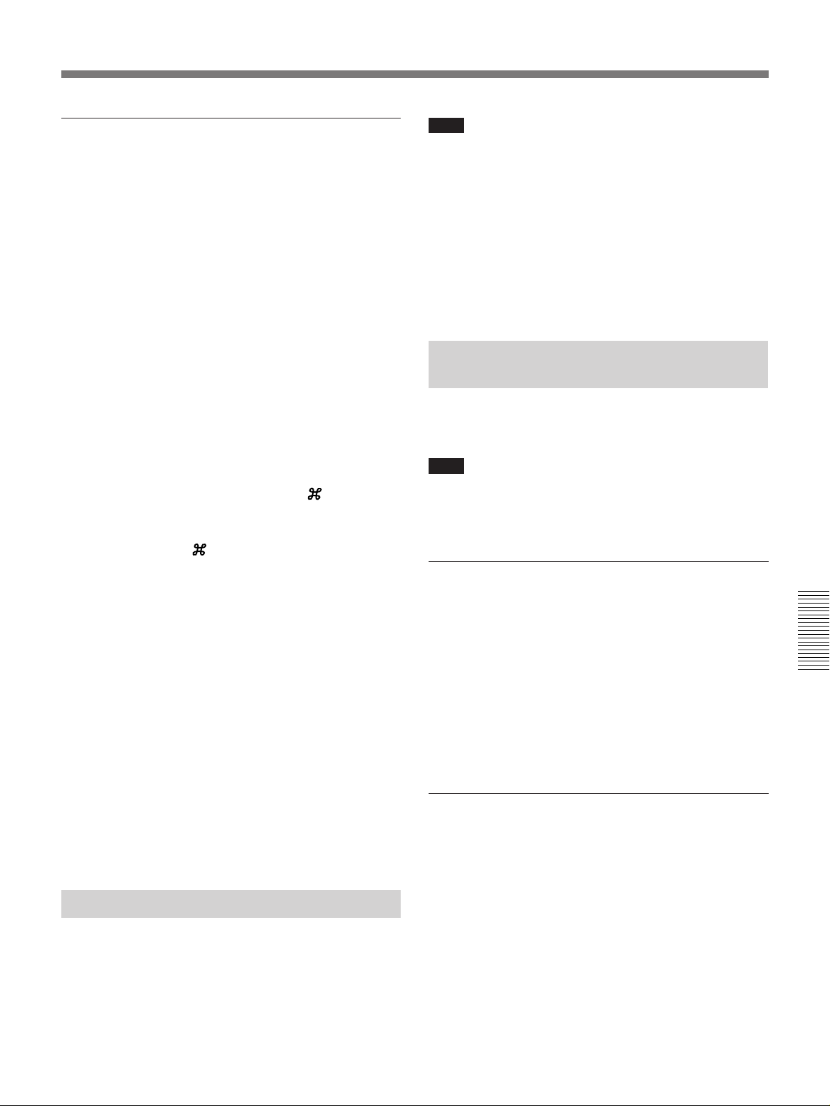
When using Power Macintosh
1 Insert floppy disk 1 supplied with the DKC-ST5
into the floppy disk drive, and copy the DKC-ST5
for Mac.sea #1 file on the floppy disk into a folder
created on the hard disk.
2 Remove floppy disk 1 from the drive.
3 Insert floppy disk 2 into the drive, and copy the
DKC-ST5 for Mac.sea #2 file on the floppy disk
into that folder on the hard disk into which you
copied the DKC-ST5 for Mac.sea #1 file in step 1.
4 Double click “DKC-ST5 for Mac.sea #1” to launch
it.
5 In the dialog box that has appeared, select “DKC-
ST5 for Mac.sea #2” and click the Load button.
A dialog box containing the Extract
appears.
E button
Note
The control software will hang if after starting it you
do any of the following on the DKC-ST5:
•Power off the digital processor
•Disconnect the camera cable from the digital
processor or camera head
•Disconnect the SCSI interface between the DKC-ST5
and the computer
If the control software hangs, it will be necessary to
restart the system.
Uninstalling the Control
Software
Use the following procedure to uninstall the control
software.
Note
Before beginning this operation, check the following.
•The control software is not running.
•No Readme file about the control software is open.
6 Click the Extract E button.
A folder named DKC-ST5 for Mac vn.nn (“n.nn”
represents the version number) is created, and the
following files are created in that folder.
• DKC-ST5 for Mac: DKC-ST5 control software
executable file
• Expander for Mac: Expander executable file
• Readme-DKC contents
• Readme-DKC1 to Readme-DKC4: provide
descriptions of DKC-ST5 for Mac
• Readme-EXP: provides a description of
Expander for Mac
Once the control software installation is finished, you
may delete both the DKC-ST5 for Mac.sea #1 and
DKC-ST5 for Mac.sea #2 files from the hard disk.
Using the Control Software
Installing the control software simultaneously installs
Readme files. For details of how to use the control
software, consult the Readme files.
When using Microsoft Windows 95/98
1 Open the Microsoft Windows 95/98 Control Panel
window, and double-click “Add/Remove
Programs,” then click on “Install/Uninstall.”
2 Select “DKC-ST5” from the list of programs, and
click the Add/Remove button.
Thereafter, follow the directions given in dialog
boxes.
When using Power Macintosh
1 Delete the DKC-ST5 for Mac vn.nn folder that was
created through execution of the control software
installation process.
2 Delete the DKC-ST5 Preferences file from the
Preferences folder under the System folder.
Chapter 5 Using the Control Software
Chapter 5 Using the Control Software 61
Page 62

Page 63
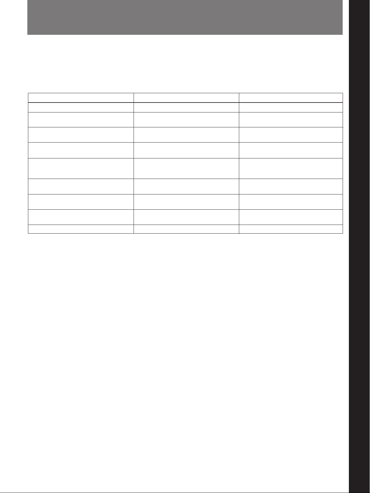
Error Messages
Chapter 6 Maintenance
If the system is unable to operate normally because of a particular
combination of operations, an error message may appear on the monitor.
The following table lists the error messages, with their meanings and
appropriate action to take.
Message Meaning
BB:NG Please try again
COMMANDER IS LOCKED
FLASH CALIBRATION: NG
MEMORY FULL The memory for captured images is full.
MEMORY IS LOCKED
Not available during transferring image
data
Not available except AWB setting as CTemp
Not available in E-ZOOM mode This operation is not possible in the
WB:NG Please try again White balance adjustment failed. Check the conditions, and try again.
Black balance adjustment failed.
The remote controller has been locked
by the computer.
Flash calibration failed.
The currently selected memory for
captured images is locked (writeprotected).
This operation is not possible during
image data transfer.
This operation is not possible unless the
“C-TEMP” menu item is set to “AWB.”
electronic zoom mode.
Action to take
Check the conditions, and try again.
Unlock the remote controller from the
computer.
Check the condition of the flash, subject
and so forth, and try again.
Delete images no longer required from
memory.
Either unlock this memory, or select a
different memory.
Wait until image data transfer is
finished.
Set the “C-TEMP” menu item to “AWB.”
Exit from the electronic zoom mode and
retry.
Chapter 6 Maintenance 63
Chapter 6 Maintenance
Page 64

Tr oubleshooting
If a problem should occur when you are using the system, consult the
following troubleshooting chart, and carry out any suggested action.
If you are unable to resolve the problem, or if the problem occurs
persistently, contact your Sony dealer.
Symptom Cause / items to check / action to take
The system does not power on. Is the power cord connected correctly?
The buttons of the remote controller do not
operate.
There is no image on the monitor.
The monitor image colors are peculiar.
Captured images are blurred.
The picture quality from the camera is poor. Is the attenuation compensation setting for the camera cable set correctly?
Changing the camera settings does not affect the
image on the monitor.
There are a number of horizontal lines on a live
image.
When I change the focus and zoom settings, the
lens does not respond.
When an image is transferred to a computer and
displayed, the color gradation is completely
different from that in the monitor image.
When a captured image is displayed on the
monitor, the color gradation is peculiar.
When shooting with the flash on, the image
flickers at the instant an image is captured to
memory.
The color temperature of the live image
sometimes changes under fluorescent lighting.
However I change the settings, the dynamic
range of an image transferred to the computer
does not fill the 0 to 255 range.
I have used cropping on images captured to
Chapter 6 Maintenance
memory to transfer them part by part to the
computer. However, it does not seem to be
possible to join them back together again
correctly.
The computer does not recognize the digital
processor.
SCSI operations are unstable.
The lens does not work. Didn’t you connect or disconnect the lens cable with the system power on?
Is the remote controller cable connected correctly?
Are the video signal cables (R, G, B) connected correctly?
There may be blurring when photographing a fast-moving subject. This is
not a fault.
Set DIP switch 1 according to the length of the cable.
If the image being displayed is from memory, there will be no change. In
this case, switch from memory monitor mode to live monitor mode.
When shooting a moving subject, this may occur in the image on the
monitor. This is not a fault, and does not affect captured images.
Set the FOCUS/ZOOM switch to the POWER position.
In this system, when an image is displayed on the monitor the color lookup table is optimized to give the best gradation. The image may not
therefore necessarily appear identically on a computer screen.
Have the gamma settings been changed since the image was captured?
For the same reason as in the previous item, if the current gamma settings
are different from the gamma settings when the image was captured, it will
not be displayed correctly on the monitor.
This is not a fault.
This is caused by the electronic shutter reacting to the high frequency
variations in intensity which are a characteristic of fluorescent lighting, and
is not a fault.
When using flash the images shot are not affected; if not using flash, as
far as possible shoot under tungsten lighting.
Is the “CONTRAST” setting in the PICTURE menu set to a negative
(See page 55.)
value?
Because of the details of the image processing algorithm, it is not in
general possible to join parts of images back together without subtle
problems of pixel mismatch.
• Did you power on the system using the correct procedure?
21.)
• Is the SCSI cable connected correctly?
• Is there a SCSI ID conflict?
• Is the SCSI terminator fitted correctly?
(See pages 9 and 11.)
(See pages 49 and 50.)
(See page 46.)
(See page 46.)
(See page 50.)
(See pages 46 to 49.)
(See page 48.)
(See page 46.)
(See page
64 Chapter 6 Maintenance
Page 65

Notes on Use
Appendix
Do not obstruct ventilation openings
To prevent the camera and processor from overheating, do not obstruct
ventilation openings, by for example wrapping the camera and processor in
a cloth while they are in operation.
Operation and storage locations
Avoid operation or storage in any of the following places.
•Location subject to extremes of temperature (operating temperature range
5°C 35°C (41°F to 95°F))
•Location subject to direct sunlight for long periods, or close to heating
appliances (Note that the interior of a car left in summer with the
windows closed can exceed 50°C (122°F).)
•Damp or dusty places
•Location subject to severe vibrations
•Location near equipment generating strong electromagnetic emissions
•Location near transmitting stations generating strong radio waves
Operate the processor in a horizontal position
The processor is designed to be operated in a horizontal position. Do not
operate it on its side, or tilted through an excessive angle (exceeding 20°).
Avoid violent impacts
Dropping the camera and processor, or otherwise imparting a violent shock
to them, is likely to cause them to malfunction.
Care
If the casing or panel is dirty, wipe it gently with a soft dry cloth. In the
event of extreme dirt, use a cloth steeped in a neutral detergent to remove
the dirt, then wipe with a dry cloth. Applying alcohol, thinners,
insecticides, or other volatile solvents may result in deforming the casing
or damaging the finish.
Shipping
Pack the camera and processor their original carton or equivalent packing,
and take care not to impart violent shocks in transit.
Appendix 65
Appendix
Page 66

Specifications
Camera head
Imaging element2/3-inch CCD, with approximately
1,400,000 pixels
Effective image area
1,280 (H) × 1,024 (V) pixels
Pixel offset Vertical and horizontal
Photography system
3 elements
2
Lens mount
Auto exposure • Program (live mode, with flash
Exposure compensation
Sensitivity
Live mode Auto (ISO 20 to 640)
Still mode ISO 20, 40, 80, 160
White balance • Auto (with flash on/off)
Electronic shutter
Live mode Auto
Still mode 4, 2, 1, 1/2, 1/3, 1/4, 1/6, 1/12,
Input/output and control connectors
Power requirements
Current consumption
Appendix
Ambient operating temperature
Ambient storage temperature
External dimensions (w/h/d)
Mass Approx. 1,3kg (2 lb 13 oz)
/3-inch 48 mm bayonet mount
off)
• Shutter priority (with flash off)
• Aperture priority (with flash off)
• Manual
–9 to +9
• Manual (R and B gains: –127 to
+127)
1/25, 1/50, 1/60, 1/125, 1/250,
1/500, 1/1000, 1/2000, 1/5000,
1/10000
PROCESSOR: 26-pin, analog
RGB (diagonal color offset)
LENS 1: 20-pin
LENS 2: 12-pin
VIDEO OUT: BNC type
REMOTE: 12-pin
VF: 8-pin, DIN
FLASH: X contact (terminal
voltage: 400 V or less)
12 V DC
6.0 W
5°C (41°F) to 35°C (95°F)
–20°C (–4°F) to +60°C (140°F)
120 × 90 × 188.5 mm
3
/4 × 3 5/8 × 7 1/2 inches)
(4
Digital processor
Input A/D 10-bits/color (R, G, B)
Gamma STANDARD, PRESET1,
PRESET2, PRESET3
Input LUT All 10-bit (R, G, B)
Output LUT All 8-bit (R, G, B)
Processing
Sharpness OFF, LOW, MIDDLE, HIGH
Contrast –5 to +5
Masking OFF, LOW, MIDDLE, HIGH
Memory Image memory size: 1,300 (H)
× 1,030 (V) × 3 (R, G, B)
× 8 (bits)
External interface SCSI: SCSI-2
Transfer method: Asynchronous
transfer
Data bus width: 8 bits
Termination method: Single-Ended
Input/output and control connectors
CAMERA: 26-pin
SCSI connectors (loop-through):
50-pin, half-pitch
FLASH: X contact (terminal
voltage: Less than 400 V)
RS-232C: D-sub 9-pin (undefined)
FS: Mini-jack
VIDEO: BNC type
S-VIDEO: Mini DIN 4-pin
R, G, B, and SYNC: BNC-type
R, G, B: 0.7 Vp-p, 75 ohms
SYNC: 4 Vp-p, 75 ohms
Note
Pixel skew offset signal is output
as it is.
Others Camera cable length compensation:
10 m/25 m
Power requirements
NTSC model: 120 V, 50 Hz/
60 Hz
PAL model: 220 to 240 V, 50 Hz/
60 Hz
Current consumption
NTSC model: 0.45 A
PAL model: 0.35 A
External dimensions (w/h/d): 211 ×
365 × 128.5 mm
3
/8 × 14 3/8 × 5 1/8 inches)
(8
Mass: Approx. 6 kg (13 lb 3 oz)
66 Appendix
Page 67

Accessories supplied
Remote controller (1)
Camera cable (1)
AC power cord (1)
Ferrite cores (4 for NTSC model, 7 for PAL model)
3.5-inch floppy disks containing the control software
(4)
Operating Instructions (1)
Appendix 67
Appendix
Page 68

Sony Corporation Printed in Japan
 Loading...