

Page 1

Film-Tech
The information contained in this Adobe Acrobat pdf
file is provided at your own risk and good judgment.
These manuals are designed to facilitate the
exchange of information related to cinema
projection and film handling, with no warranties nor
obligations from the authors, for qualified field
service engineers.
If you are not a qualified technician, please make no
adjuatments to anything you may read about in these
Adobe manual downloads
www.film-tech.com
Page 2
English
WARNING
To prevent fire or shock hazard, do not
expose the unit to rain or moisture.
English
Using this unit at a voltage other than 120V may
require the use of a different line cord or attachment
plug, or both. To reduce the risk of fire or electric
shock, refer servicing to qualified service personnel.
To avoid electrical shock, do not open
the cabinet. Refer servicing to qualified
personnel only.
THIS APPARATUS MUST BE EARTHED.
VORSICHT
Um Feuergefahr und die Gefahr eines
elektrishcen Schlages zu vermeiden, darf
das Gerät weder Regen noch Feuchtigkeit
ausgesetzt werden.
Um einen elektrischen Schlag zu
vermeiden, darf das Gehäuse nicht
geöffnet werden. Überlassen Sie
Wartungsarbeiten stets nur einem
Fachmann.
DIESES GERÄT MUSS GEERDET
WERDEN.
For customers in the USA
WARNING
This equipment has been tested and found to comply
with the limits for a Class A digital device, pursuant to
Part 15 of the FCC Rules. These limits are designed to
provide reasonable protection against harmful
interference when the equipment is operated in a
commercial environment. This equipment generates,
uses, and can radiate radio frequency energy and, if
not installed and used in accordance with the
instruction manual, may cause harmful interference to
radio communications. Operation of this equipment in
a residential area is likely to cause harmful interference
in which case the user will be required to correct the
interference at his own expense.
You are cautioned that any changes or modifications
not expressly approved in this manual could void your
authority to operate this equipment.
The shielded interface cable recommended in this
manual must be used with this equipment in order to
comply with the limits for a digital device pursuant to
Subpart B of Part 15 of FCC Rules.
This symbol is intended to alert the user
to the presence of important operating
and maintenance (servicing) instructions
in the literature accompanying the
appliance.
For the customers in Europe
This product with the CE marking complies with both
the EMC Directive (89/336/EEC) and the Low Voltage
Directive (73/23/EEC) issued by the Commission of the
European Community.
Compliance with these directives implies conformity to
the following European standards:
• EN60950: Product Safety
• EN55103-1: Electromagnetic Interference (Emission)
• EN55103-2: Electromagnetic Susceptibility
(Immunity)
This product is intended for use in the following
Electromagnetic Environment(s):
E1 (residential), E2 (commercial and light industrial),
E3 (urban outdoors) and E4 (controlled EMC
environment, ex. TV studio).
Pour les clients européens
Ce produit portant la marque CE est conforme à la fois
à la Directive sur la compatibilité électromagnétique
(EMC) (89/336/CEE) et à la Directive sur les basses
tensions (73/23/CEE) émises par la Commission de la
Communauté européenne.
La conformité à ces directives implique la conformité
aux normes européennes suivantes:
• EN60950: Sécurité des produits
• EN55103-1: Interférences électromagnétiques
(émission)
• EN55103-2: Sensibilité électromagnétique
(immunité)
Ce produit est prévu pour être utilisé dans les
environnements électromagnétiques suivants:
E1 (résidentiel), E2 (commercial et industrie légère),
E3 (urbain extérieur) et E4 (environnement EMC
contrôlé ex. studio de télévision).
Für Kunden in Europa
Dieses Produkt besitzt die CE-Kennzeichnung und
erfüllt sowohl die EMV-Direktive (89/336/EEC) als
auch die Direktive Niederspannung (73/23/EEC) der
EG-Kommission.
Die Erfüllung dieser Direktiven bedeutet Konformität
für die folgenden Europäischen Normen:
• EN60950: Produktsicherheit
• EN55103-1: Elektromagnetische Interferenz
(Emission)
• EN55103-2: Elektromagnetische Empfindlichkeit
(Immunität)
Dieses Produkt ist für den Einsatz unter folgenden
elektromagnetischen Bedingungen ausgelegt:
E1 (Wohnbereich), E2 (kommerzieller und in
beschränktem Maße industrieller Bereich), E3
(Stadtbereich im Freien) und E4 (kontrollierter EMVBereich, z.B. Fernsehstudio)
1(E)
Page 3

WARNING: THIS WARNING IS APPLICABLE FOR
USA ONLY.
If used in USA, use the UL LISTED power cord
specified below.
DO NOT USE ANY OTHER POWER CORD.
Plug Cap Parallel blade with ground pin (NEMA 5-15P
Configuration)
Cord Type SJT, three 16 or 18 AWG wires
Length Less than 2.5 m (8 ft 3 in)
Rating Minimum 10 A, 125 V
Using this unit at a voltage other than 120 V may
require the use of a different line cord or attachment
plug, or both. To reduce the risk of fire or electrical
shock, refer servicing to qualified service personnel.
WARNING: THIS WARNING IS APPLICABLE FOR
OTHER COUNTRIES.
1. Use the approved Power Cord/Plug with earthing-
contacts that conforms to the safety regulations of
each country if applicable.
2. Use the Power Cord/Plug conforming to the
following ratings, which meets power supply
voltage of each country.
• Rating: 10 A or more
AVERTISSEMENT: CET AVERTISSEMENT EST
VALABLE POUR LES AUTRES
PAYS.
1. Utilisez le cordon et la fiche d’alimentation avec
prise de terre, approuv és et confromes à la
réglementation relative à la sécurité, adoptée par
chaque pays.
2. Utilisez le cordon et la fiche d’alimentation
correspondant aux caractéristiques suivantes, en
fonction de la tension d’alimentation secteur de
chaque pays.
• Ampérage: 10 A ou plus
WARNUNG: Die folgenden Warnungsangaben
gelten fur das Modell fur andere
Länder.
1. Das Nezkabel/der Netzstecher mus einen
Erdungskontakt besitzen und den
Sicherheitsbestimmungen Ihres Landes genüngen.
2. Das Netzkabel muß je nach der Netzspannung
Ihres Landes fur folgende Spannungen und Ströme
ausgelegt sein.
• Stromstärke 10 A oder mehr
2(E)
Page 4

Table of Contents
Overview.....................................................................................................4
Overview of SDDS Player System ............................................4
Principal Features.......................................................................4
System Configuration................................................................................5
Location and Function of Parts................................................................6
DFP-D2500 Front Panel.............................................................6
DFP-D2500 Connector Panel.....................................................8
DFP-D2500 Connector Pin Assignment ....................................9
Operation..................................................................................................12
Loading Film............................................................................12
Specifications............................................................................................13
SDDS Digital Audio Signals....................................................13
General .....................................................................................13
I/O Characterlistics ..................................................................14
Accessories and Related Equipment ........................................14
3(E)
Page 5

Overview
Overview of SDDS Player System
The SDDS (Sony Dynamic Digital Sound)1) Player
System is a system that reads digital audio data
recorded on 35 mm movie film in the SDDS format,
and feeds high quality digital sound to a theater sound
system.
A movie film should be played back without any
breaks. The digital audio signals recorded on the P
side and S side of the 35 mm film are corrected by the
error correction circuit. Furthermore, if a problem
where the audio signal cannot be corrected by the
error correction circuit occurs, a film in the SDDS
format can be corrected by reading the backup data
recorded on the other side of the film and played back
immediately. This allows the system to continue
playback without any breaks.
The SDDS system has a wide range of functions and
capabilities designed to meet the rigorous standards of
film sound post-production and of the exhibition
cinema. The system is also designed to be configured
in a number of variations for maximum flexibility in
installation.
Principal Features
This system is comprised of the DFP-R3000 Digital
Film Sound Reader and the DFP-D2500 Film Sound
Decoder.
The principal features of this system are as follows.
Playback of 8 channels of digital audio
signals recorded in the SDDS format
The system can read 8 channels of digital audio
signals recorded in the SDDS format on the P
(picture) and S (sound) sides of the film. It features
digital processing, for little or no signal degradation
during playback.
P side
S side
Fully digital audio signal path
The DFP-D2500 is a digital cinema processor that
Utilizes Digital Signal Processing (DSP) techniques
to perform essential SDDS track decoding and room
equalization. The unit performs all audio signal
processes in the digital domain. Analog input signals
are first converted to 20 bit PCM data, then
processed. Therefore, adjustments that have been
historically performed in the analog domain (i.e.,
volume adjustment, room equalization, etc.), can now
be adjusted digitally. This ensures more stable room
equalization and audio volume adjustment in the
theater.
C (center)
L (left)
LC (left center)
SL (surround left)
R (right)
RC (right center)
SR (surround right)
SW (sub-woofer)
High quality A/D and D/A converters
High quality 20-bit A/D and 20-bit D/A converters
are used to ensure the optimum resolution of the input
and output signals. These converters are operated at a
sampling frequency (Fs) of 44.1 kHz (44,100 samples
per second).
Bypass function
The DFP-D2500 can output the auxiliary input signals
with or without processing by equalizers or for level
control. This allows the unit to connect to various
types of devices.
........................................................................................................................................................................................................
1) SDDS is a registered trademark of Sony Corporation.
4(E)
Page 6
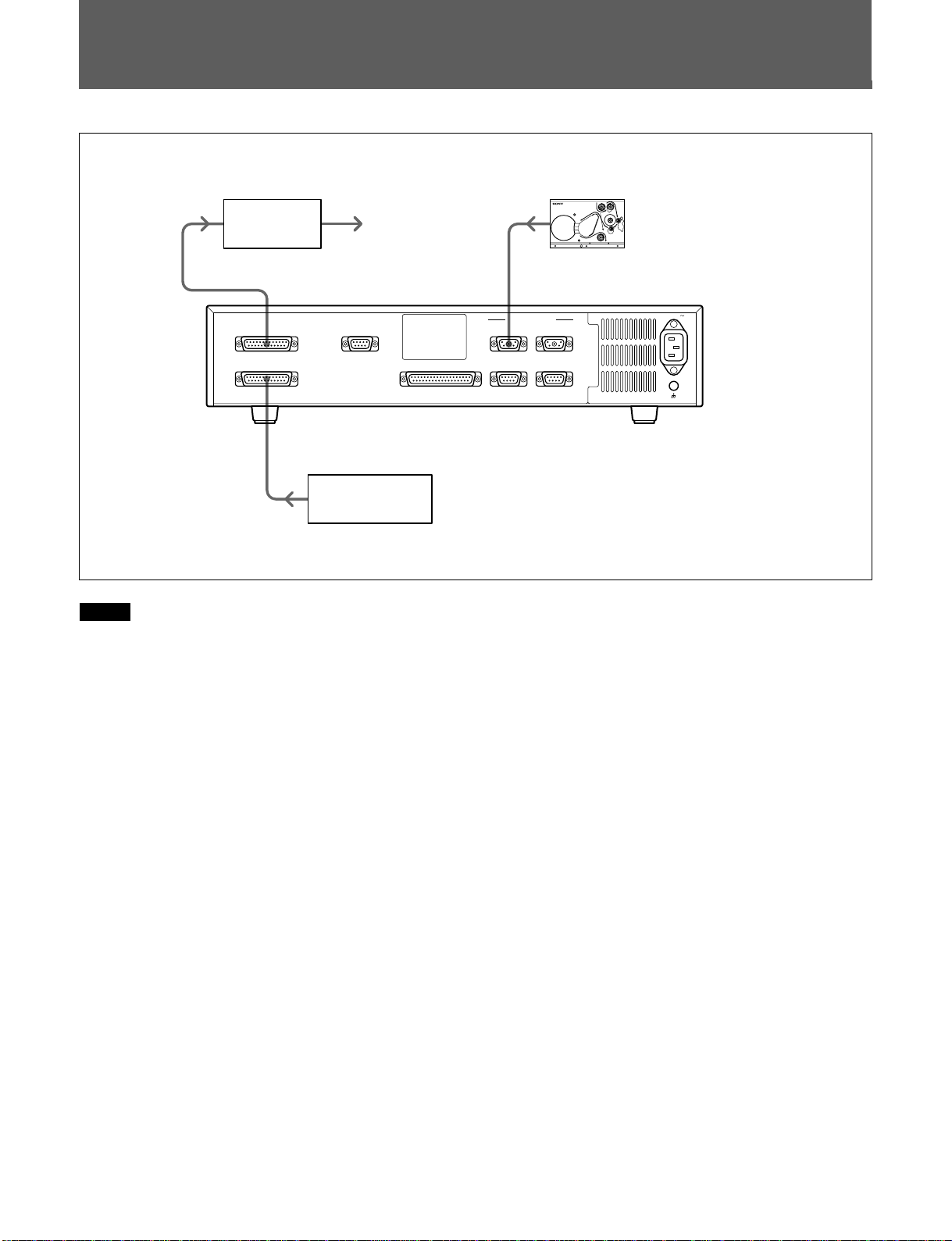
System Configuration
Power
amplifier
SYSTEM OUTPUT
Theater speaker
REMOTE
LEVEL CONTROL
PROJECTOR I/O
READER 1
DFP-R3000
READER 2
IN
PASS
OUT
DFP-D2500
AC IN
AUX INPUT AUTOMA TION RS-232C
Cinema sound
equipment
Note
For details about installation and connection of this
system, contact your Sony service or sales
representative.
RS-422
5(E)
Page 7
Location and Function of Parts
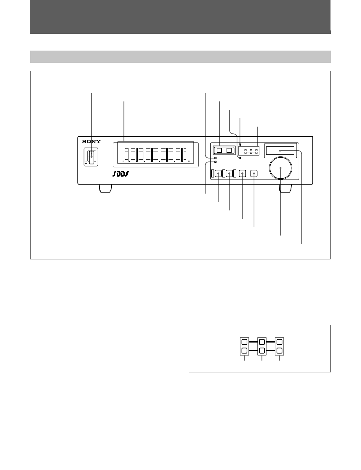
DFP-D2500 Front Panel
1Power switch
POWER
3SYSTEM OK indicator
2Level meters 4PROJECTOR indicators
5EXT FADER indicator
6DATA PRESENT indicator
7SDDS STATUS indicators
LLCCRCRSWSLSR
OVER
0
-
6
-
20
-
34
-
60
-
Sony Dynamic
Digital Sound
OVER
0
-
-
-
-
-
PROJECTOR MASTER LEVEL
6
20
34
60
21
REMOTE
BYPASS MUTE SDDS AUX
DIGITAL FILM SOUND DECODER DFP-D2500
DATA PRESENT
SDDS STATUS
P
S
EXT FADERSYSTEM OK
MASTER
VOLUME
qfREMOTE indicator
qdBYPASS button
qsMUTE button
qaSDDS button
0AUX button
9MASTER VOLUME dial
8MASTER LEVEL display
dB
1 Power switch
2 Level meters
Show the level of each channel.
3 SYSTEM OK indicator
•Lights when the SDDS player system is operating
normally, and goes out when the SDDS player
system error occurs.
•Goes out to indicate a system warning, for example
that the fan has stopped rotating or that there is no
backup battery.
4 PROJECTOR indicators
During playback with a changeover system, shows
which of the projectors is currently in use.
5 EXT FADER indicator
Lights when the remote fader connected to the
REMOTE LEVEL CONTROL connector activates.
When this indicator is lit, the MASTER VOLUME
control becomes disabled.
6 DATA PRESENT indicator
Lights when the unit is reading SDDS digital audio
signals and can play back.
7 SDDS STATUS indicators
Indicates the playback condition of digital audio
signals in the SDDS format.
SDDS STATUS
P
S
Green Yellow Red
P green/yellow/red indicators: Each indicator
indicates a playback condition of the digital
signals recorded on the P (picture) side of the film.
S green/yellow/red indicators: Each indicator
indicates a playback condition of the digital
signals recorded on the S (sound) side of the film.
6(E)
Page 8

When a green indicator is lit, the signals are being
played back correctly. When a red indicator goes on
frequently, it indicates that the film quality may have
degraded or the machines may be in need for
maintenance.
Even when one red indicator is lit, the unit can
continue playback without any trouble unless the
DATA PRESENT6 indicator is lit.
8 MASTER LEVEL display
Shows the master level.
9 MASTER VOLUME dial
The master volume dial is a rotary encoder which is
used to control the master volume level of all channel
outputs from the Sony DFP-D2500. This volume
control allows the user to set the master volume level
between +10dB and -∞.
0 AUX button
Press this button twice to select analog audio
auxiliary signals input to the AUX INPUT connector.
When you press this button first time, the button
indicator blinks. When you press the button again, the
button lights. This is a safety feature to ensure the
proper selection. Thus, even when you press the
button accidentally, the input signal will not be
changed unless you press the button again.
qf REMOTE indicator
Lights when the system is being controlled remotely.
For details, contact your sony service or sales
representative.
qa SDDS button
Press this button twice to select digital audio signals
recorded in the SDDS format as a input. When you
press this button first time, the button indicator blinks.
When you press the button again, the button lights.
This is a safety feature to ensure the proper selection.
Thus, even when you press the button accidentally,
the input signal will not be changed unless you press
the button again.
qs MUTE button
Press this button, turning it on, to mute system output.
qd BYPASS button
Press this button to output the audio signals input to
the AUX INPUT connector without any processing.
However, when the power of the unit is turned off and
while the system is starting up, the unit is in this
bypass mode where auxiliary input signals are output
without any processing.
7(E)
Page 9
Location and Function of Parts
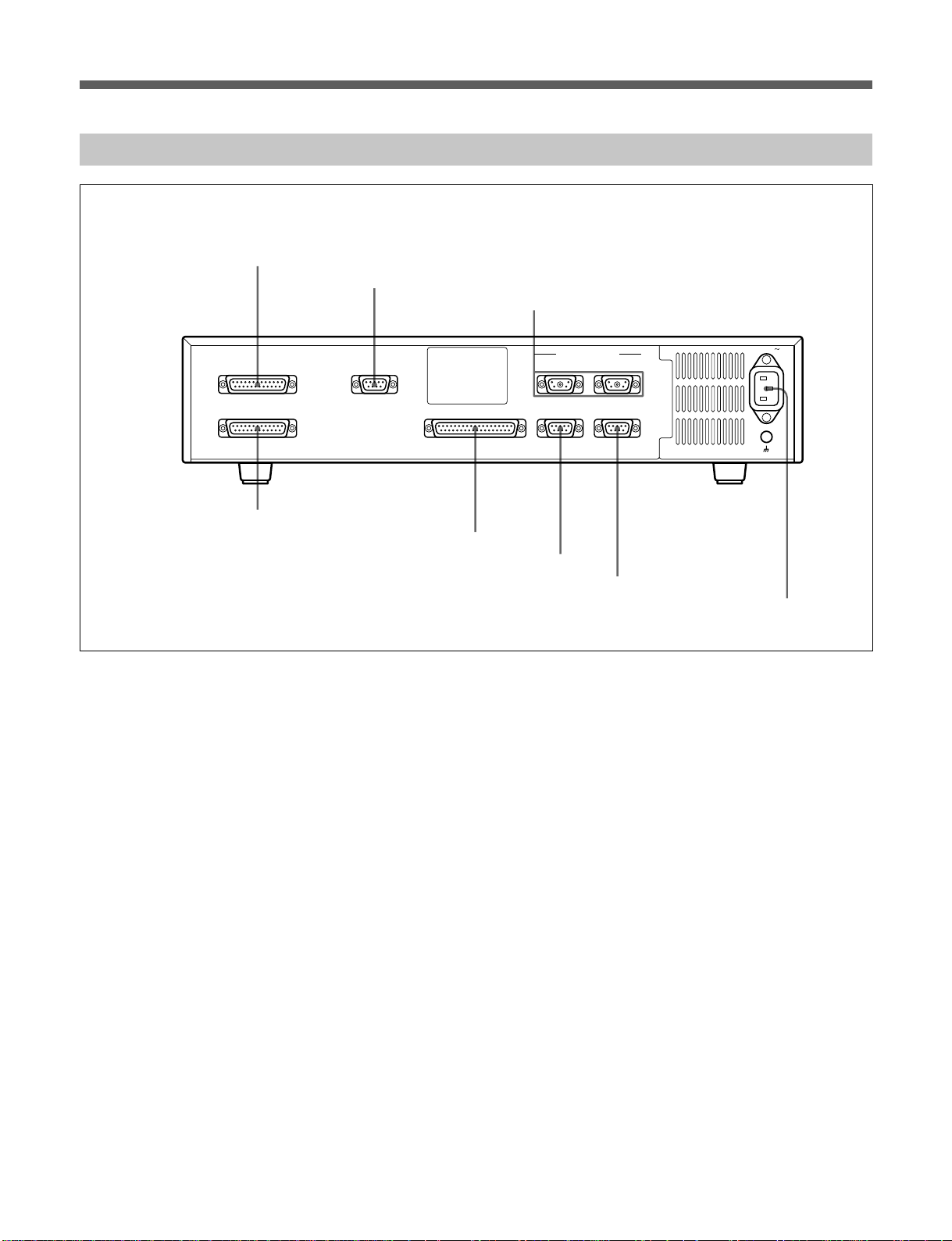
DFP-D2500 Connector Panel
1SYSTEM OUTPUT connector
2REMOTE LEVEL CONTROL connector
3READER 1/2 connectors
SYSTEM OUTPUT
AUX INPUT AUTOMATION RS-232C
8AUX INPUT connector
REMOTE
LEVEL CONTROL
7AUTOMATION connector
1 SYSTEM OUTPUT connector
Balanced 8-channel analog audio output connector.
This connection is used to connect to the amplifier
system of the theater “B-Chain”.
2 REMOTE LEVEL CONTROL connector
Connect external remote fader(100 kΩ Type B
Curve).
PROJECTOR I/O
READER 1
6RS-232C connector
5RS-422 connector
READER 2
RS-422
AC IN
4AC IN- socket
5 RS-422 connector
Connect the central control equipment of the theater.
For details, contact your Sony service or sales
representative.
6 RS-232C connector
Connect an IBM PC/AT or compatible computer.
For details, contact your Sony service or sales
representative.
3 READER 1/2 connectors
Connect to the DFP-R3000 for input of digital audio
signals read from the film. Use the READER 1
connector in a system with one projector, and use
both the READER 1 and READER 2 connectors in a
changeover playback system.
4 AC IN - socket
Connect the power cord.
8(E)
7 AUTOMATION connector
This is a connector for automatic system control.
For details, contact your Sony service or sales
representative.
8 AUX INPUT connector
Balanced 8-channel analog audio input connector.
This connector can be used to interface playback
systems from other manufacturers to the DFP-D2500.
Page 10
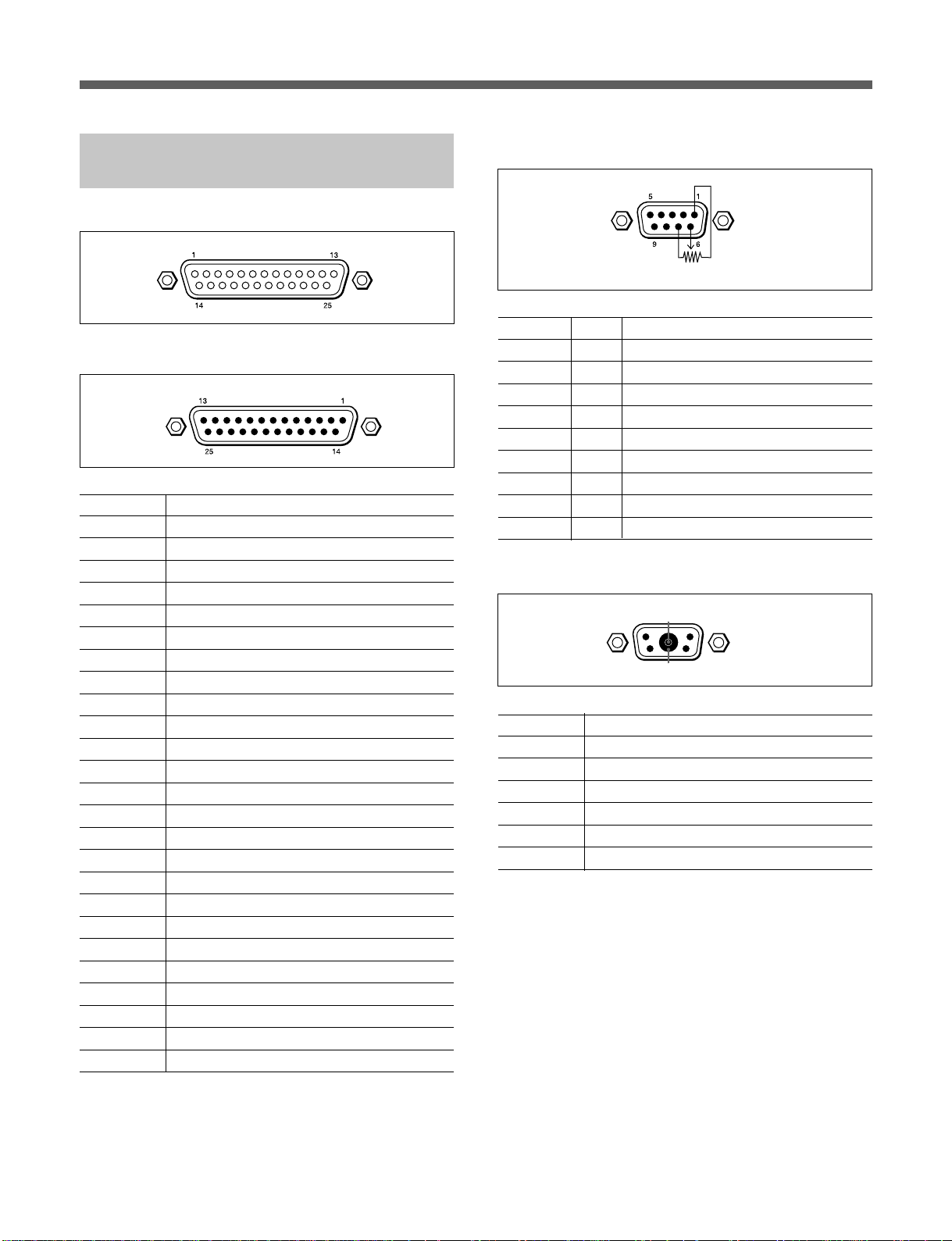
DFP-D2500 Connector Pin Assignment
1 SYSTEM OUTPUT connector
8 AUX INPUT connector
Pin No. Signal
1 LEFT GND
2 LEFT HOT
3 LEFT CENTER COLD
4 CENTER GND
5 CENTER HOT
6 RIGHT CENTER COLD
7 RIGHT GND
8 RIGHT HOT
9 SURROUND LEFT GND
10 SURROUND LEFT COLD
11 SURROUND RIGHT COLD
12 SUB WOOFER COLD
13 SUB WOOFER GND
14 LEFT COLD
15 LEFT CENTER GND
16 LEFT CENTER HOT
17 CENTER COLD
18 RIGHT CENTER GND
19 RIGHT CENTER HOT
20 RIGHT COLD
21 NC
22 SURROUND RIGHT GND
23 SURROUND LEFT HOT
24 SURROUND RIGHT HOT
25 SUB WOOFER HOT
2 REMOTE LEVEL CONTROL connector
100kΩB
Pin No. I/O Signal
1 – GND
2 I MAN FADE
3 –
4 –
5 I EXT FADER EN
6 I AUTO FADE
7ODC
8 O REMTLY
9 – GND
3 READER 1/2 connector
A1
12
34
G1
Pin No. Signal
1 DC 24V
2NC
3 GND(DC24V)
4 CABLE SHIELD
A1 DATA
G1 DATA GND
9(E)
Page 11
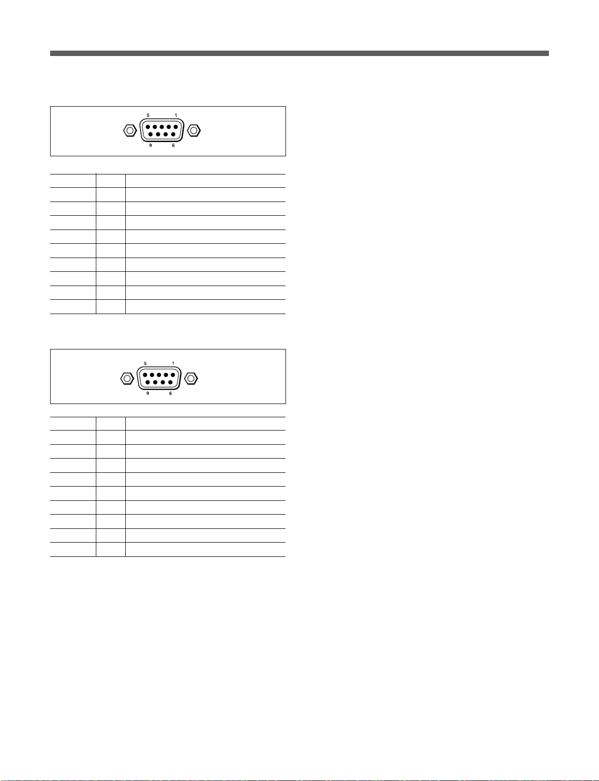
Location and Function of Parts
5 RS-422 connector
Pin No. I/O Signal
1 – GND
2 O RTS(+)
3 O RTS(–)
4 O TXD(+)
5 O TXD(–)
6 I CTS(+)
7 I CTS(–)
8 I RXD(+)
9 I RXD(–)
6 RS-232C connector
Pin No. I/O Signal
1 – NC
2 I RXD
3 O TXD
4 O DTR
5 – GND
6 – NC
7 O RTS
8 I CTS
9 – NC
10(E)
Page 12
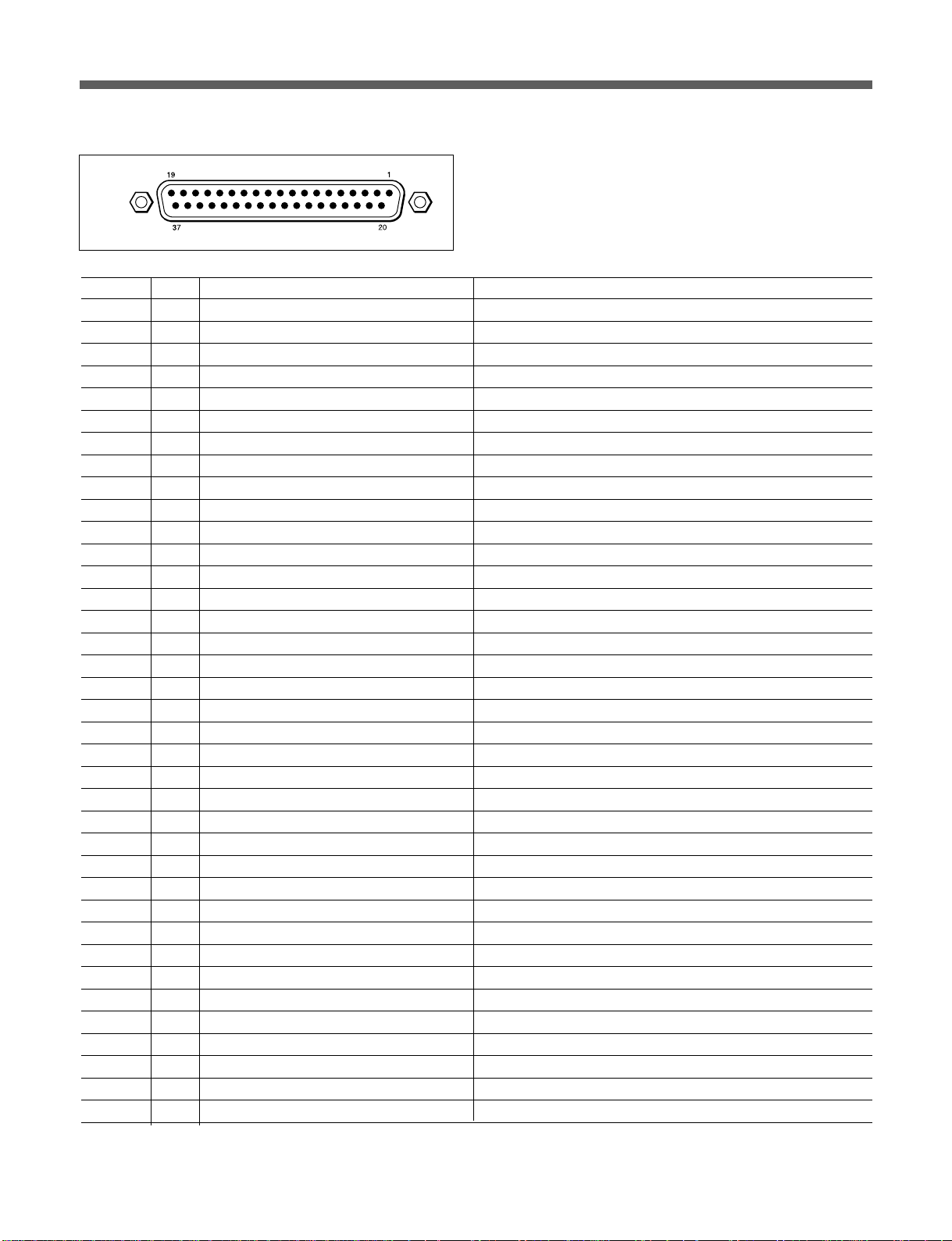
7 AUTOMATION connector
Pin No. I/O Function Signal
1 – Chassis Ground GND
2 I Projector 1 Motor Start Input: LOW = MOTOR 1 RUNNING
3 I Master Mute Command Input pulse: Low = MUTE or UNMUTE
4 I/O Preset 1 Select (SDDS) Input pulse: Low = SELECT
5 I/O Preset 2 Select (AUX) Input pulse: Low = SELECT
6 – Reserved No connections
7 – Reserved No connections
8 – Reserved No connections
9 – Reserved No connections
10 – Reserved No connections
11 – Reserved No connections
12 O MOTOR 1 Start Tally Output tally: Low = MOTOR 1 RUNNING
13 O MOTOR 2 Start Tally Output tally: Low = MOTOR 2 RUNNING
14 – Logic Common GND
15 – Logic Common GND
16 – Tally Common GND
17 – Tally Common GND
18 I Optical Change Over Command Input: Low = PEC 2, High = PEC 1
19 O Optical Change Over Tally Output tally: Low = PEC 2 selected
20 O Projector 1 Tally Output tally: Low = SDDS Reader 1 selected
21 O Projector 2 Tally Output tally: Low = SDDS Reader 2 selected
22 O Master Mute Tally Output tally: Low = Master muted
23 I Pink Noise Command Input: Low = ON
24 – Reserved No connections
25 – Reserved No connections
26 – Reserved No connections
27 – Reserved No connections
28 – Reserved No connections
29 – Reserved No connections
30 O +5V Power
31 O +5V Power
32 O SDDS Data OK (any preset active) Output pulse: Low = SDDS OK
33 I Projector 2 Motor Start Input: Low = MOTOR 2 RUNNING
34 – Reserved No connections
35 – Reserved No connections
36 O SDDS Data not OK Output pulse: Low = SDDS NG
37 I EXT FADER Command Input pulse: Low = Ex fader ON/OFF
11(E)
Page 13
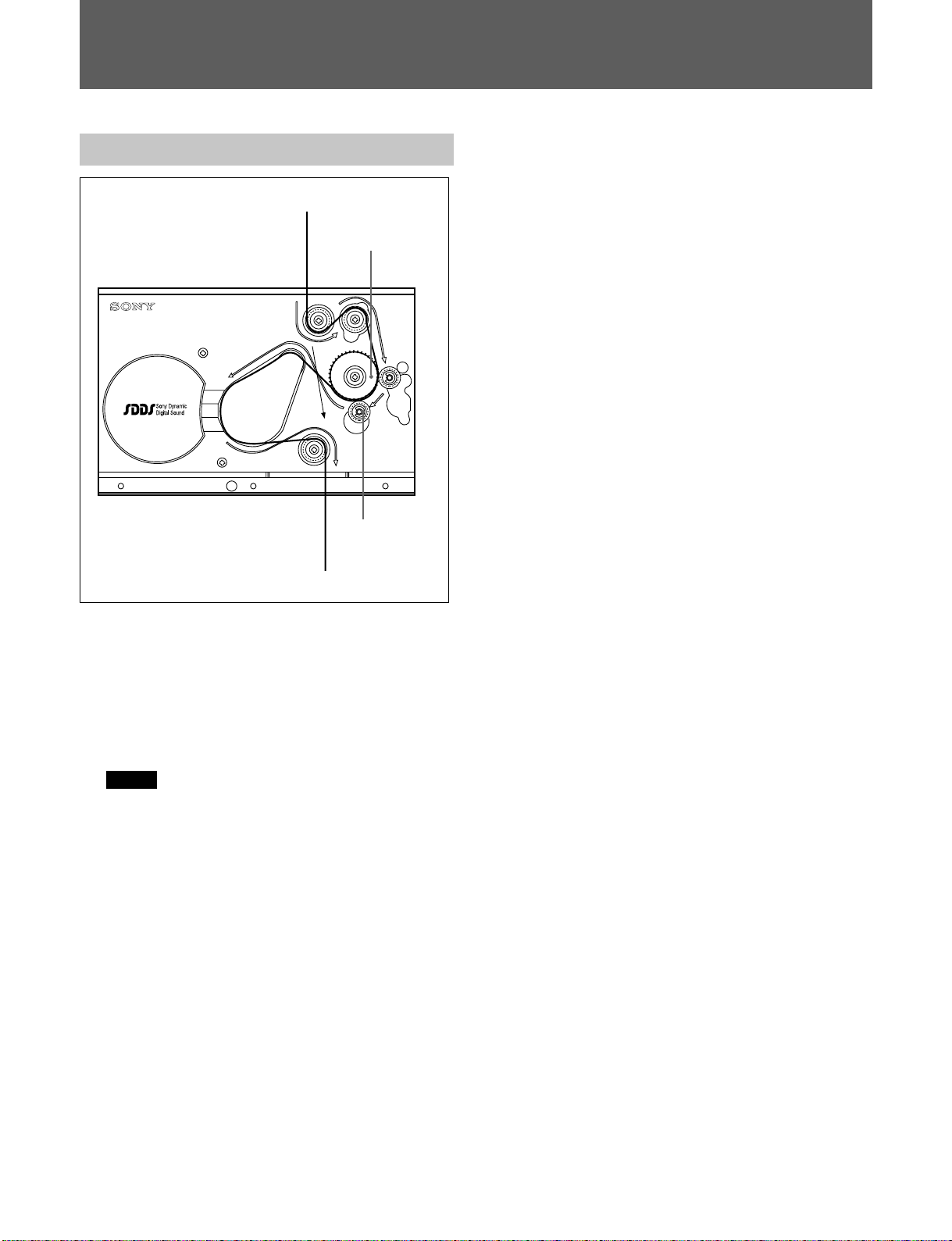
Operation
Loading Film
To the supply reel
IN
PASS
OUT
To the projector
Loading film other than SDDS
1 Pull out a suitable length of film from the supply
reel, and feed it along the path indicated by PASS
on the front panel.
Sprocket
2 Pass the film through the projector and take it up
on the takeup reel, just as you would with
ordinary movie film.
3 Return the pad roller to the original position.
Handling SDDS film
•Avoid marking the SDDS data tracks using either
adhesive labels or ink. If it is essential, keep any
marks within a frame.
•The splice length should also be not more than a
frame.
Pad roller
Film loading path in the DFP-R3000
1 Release the pad roller.
2 Pull out a suitable length of film from the supply
reel, and feed it along the path indicated by the
black line on the front panel.
Note
When other audio playback equipment is
equipped between the DFP-R3000 and projector,
be sure to feed the film with bypassing the other
equipment.
3 Pass the film through the projector and take it up
on the takeup reel, just as you would with
ordinary movie film.
4 Return the pad roller to the original position.
12(E)
Page 14

Specifications
SDDS Digital Audio Signals
Number of channels
8
Channel assignments
L: Left
LC: Left center
C: Center
RC: Right center
R: Right
SW: Sub-woofer
SL: Surround left
SR: Surround right
Sampling frequency
44.1 kHz
Frequency response
20 Hz to 20 kHz ±1.0 dB
Dynamic range More than 90 dB
Distortion Less than 0.07 %
Crosstalk Less than –80 dB
Output level –10 dBu balanced (factory seting)
General
DFP-R3000 Digital Film Sound Reader
Power requirements
DC +24 V (400 mA)
Power consumption
9.6 W
Operating temperature
5 °C to 40 °C (41 °F to 104 °F)
Operating humidity
10 % to 90 % (relative humidity)
Storage temperature
–20 °C to +60 °C
(–4 °F to +140 °F)
Mass 3.5 kg (7.7 1b)
Dimensions (w/h/d; excluding projections)
240 mm × 156 mm × 176 mm
1
/2 × 61/7 × 7 inches)
(9
Film width 35 mm
DFP-D2500 Digital Film Sound Decoder
Power requirements
100 to 240 V AC, 50/60 Hz
Power consumption
1.0 A
Peak inrush current
(1) Power ON, current probe
method: 80 A (240 V), 30 A
(100 V)
(2) Hot switching inrush current,
measured in accordance with
European standard EN55103-
1: 70 A (230 V)
Appel de courant de crête
(1) Mise sous tension (ON),
méthode de sondage du
courant: 80 A (240 V),
30 A (100 V)
(2) Mesuré conformément à la
norme européenne EN551031: 70 A (230 V)
Spitzenstrom
(1) Einschaltstrom, Stromsonde:
80 A (240 V), 30 A (100 V)
(2) Gemessen in EN55103-1:
70 A (230 V)
Operating temperature
5 °C to 40 °C (41 °F to 104 °F)
Operating humidity
10 % to 90 % (relative humidity)
Storage temperature
–20 °C to +60 °C
(–4 °F to +140 °F)
Mass Approx. 8 kg (17 1b 10 oz)
Dimensions (w/h/d; including projections)
482 mm × 103 mm × 361 mm
(19 × 3
EIA rack mount space
Height EIA 19-inch rack size
2 units (88 mm, 3
including feet)
Lock-in time 1 second max.
Lock range Rated speed ±5 %
Sync drift 20 msec max.
Sync drift rate 10 Hz/sec max.
1
/2 × 141/4 inches)
1
/2 inch, not
13(E)
Page 15

Specifications
I/O Characterlistics
PROJECTOR I/O
READER 1/2 connecters
5W1 connector (2)
INPUT
AUX INPUT connector
L, LC, C, RC, R, SW, SL, SR
D-sub 25-pin, female (2)
Impedance
10 kΩ min.
Reference level
–8.2 dBu
OUTPUT
SYSTEM OUTPUT connector
L, LC, C, RC, R, SW, SL, SR
D-sub 25-pin, male (1)
Load impedance
600 Ω max.
Reference level
–10 dBu
CONTROL I/O
REMOTE LEVEL CONTROL connector
D-sub 9-pin, female (1)
Input voltage
0 to +10 V
AUTOMATION connector
D-sub 37-pin, female (1)
RS-232C connector
D-sub 9-pin, female (1)
Transmission rate
19.2 kbps
RS-422 connector D-sub 9-pin, female (1)
Transmission rate
9.6 kbps
Accessories and Related Equipment
Accessories supplied
DFP-R3000
Operation guide (1)
Reader cable (1)
Reader mount kit (1 set)
DFP-D2500
Operation5 manual (1)
Design and specifications are subject to change
without notice.
..........................................................................................................................................................................................................
14(E)
Page 16

The material contained in this manual consists of
information that is the property of Sony Corporation and is
intended solely for use by the purchasers of the equipment
described in this manual.
Sony Corporation expressly prohibits the duplication of any
portion of this manual or the use thereof for any purpose
other than the operation or maintenance of the equipment
described in this manual without the express written
permission of Sony Corporation.
Le matériel contenu dans ce manuel consiste en
informations qui sont la propriété de Sony Corporation et
sont destinées exclusivement à l’usage des acquéreurs de
l’équipement décrit dans ce manuel.
Sony Corporation interdit formellement la copie de quelque
partie que ce soit de ce manuel ou son emploi pour tout
autre but que des opérations ou entretiens de l’équipement
à moins d’une permission écrite de Sony Corporation.
Das in dieser Anleitung enthaltene Material besteht aus
Informationen, die Eigentum der Sony Corporation sind, und
ausschließlich zum Gebrauch durch den Käufer der in
dieser Anleitung beschriebenen Ausrüstung bestimmt sind.
Die Sony Corporation untersagt ausdrücklich die
Vervielfältigung jeglicher Teile dieser Anleitung oder den
Gebrauch derselben für irgendeinen anderen Zweck als die
Bedienung oder Wartung der in dieser Anleitung
beschriebenen Ausrüstung ohne ausdrückliche schriftliche
Erlaubnis der Sony Corporation.
Page 17

Sony Corporation
Communication System Solutions Network Company
DFP-D2500/DFP-R3000
(SY)
3-205-080-01 (1)
Printed in Japan
2000. 09. 13
©2000
 Loading...