

Sony DE-451, DE-456-CK, DE-455, DE-459-CK Service manual
D-E451/E455/E456CK/E459CK
SERVICE MANUAL
Ver 1.0 1999.06
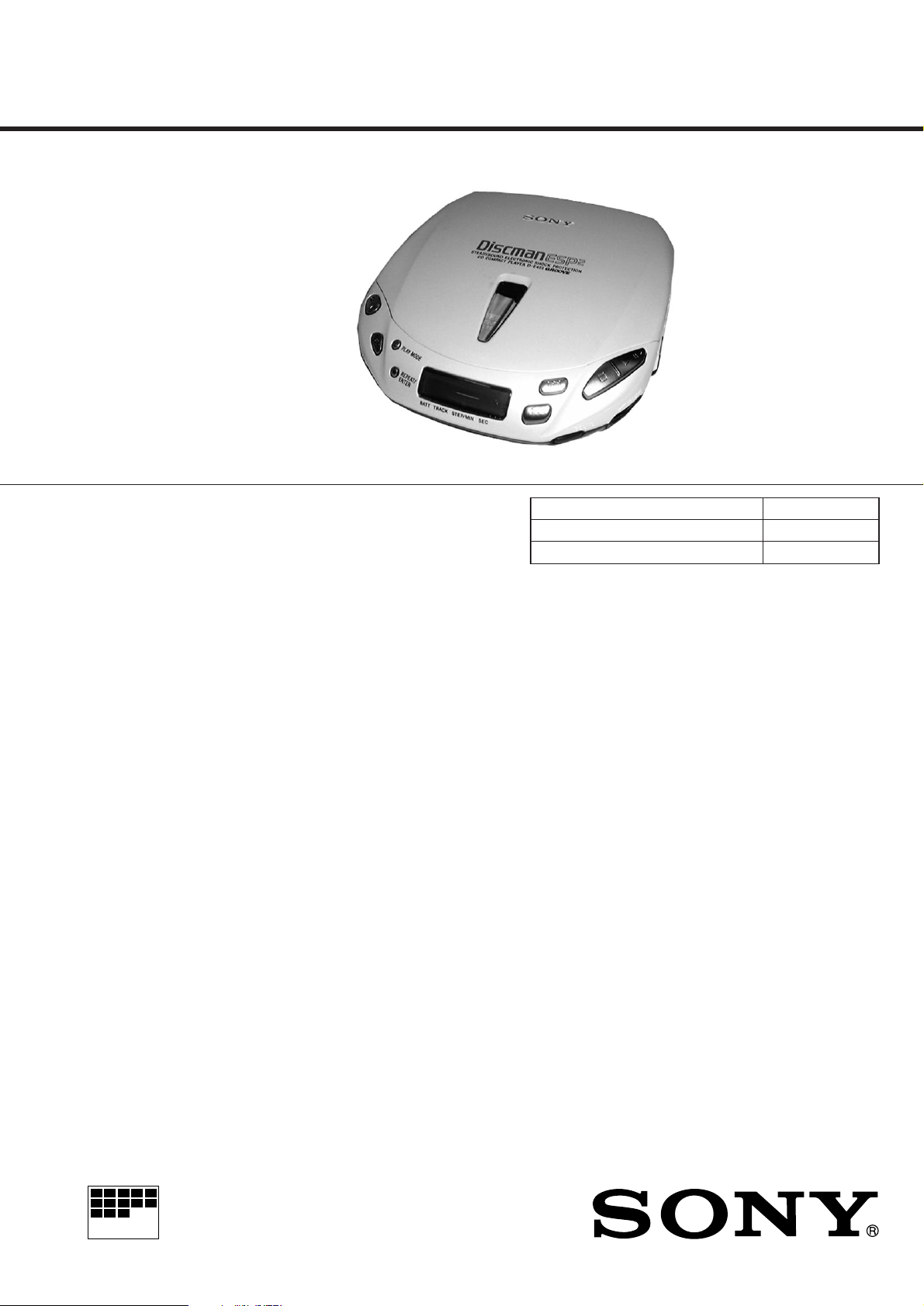
Photo : D-E451
SPECIFICATIONS
CD player
System
Compact disc digital audio system
Laser diode properties
Material: GaAIAs
Wavelength : λ= 780 nm
Emission duration: Continuous
Laser output : Less than 44.6 µW (This output
is the value measured at a distance of 200 mm
from the objective lens surface on the optical
pick-up block with 7 mm aperture. )
Error correction
Sony Super Strategy Cross Interleave Reed
Solomon Code
D-A conversion
1-bit quartz time-axis control
Frequency response
20 - 20,000 Hz+1 dB (measured by EIAJ CP-
307)
Output (at 4.5 V input level)
Headphones (stereo minijack)
15 mW + 15 mW at 16 ohms
Line output (stereo minijack)
Output level 0.7 V rms at 47 kilohms
Recommended load impedance over 10
kilohms
-2
General
Power requirements
For the area code of the model you purchased,
check the upper left side of the bar code on the
package.
• Sony BP-DM10 Rechargeable battery:
2.4 V DC, Ni-Cd, 650 mAh
Sony BP-DM20 Rechargeable battery:
2.4 V DC, Ni-MH, 1,200 mAh
• Two LR6 (size AA) batteries: 3 V DC
• AC power adaptor (DC IN 4.5 V jack):
US model: 120 V, 60 Hz
• Sony DCC-E245 car battery cord for use on
car battery : 4.5V DC
Dimensions (w/h/d) (without projecting parts and
controls)
Approx. 129 x 28 x 146 mm
( 51/8 x 11/8 x 53/4 in.)
Mass (without rechargeable battery)
Approx. 220 g (7.8 oz)
Operating temperature
5°C - 35°C (41°F - 95°F)
US Model
Model Name Using Similar Mechanism D-E441
CD Mechanism Type CDM-2811EAA
Optical Pick-up Type DAX-11E
Supplied accessories
For the area code of the model you purchased,
check the upper left side of the bar code on the
package.
D-E451
AC power adaptor (1)
Headphones (1)
D-E455
AC power adaptor (1)
Headphones with remote control (1)
Rechargeable battery (1)
D-E456CK
AC power adaptor (1)
Headphones (1)
Car battery cord (1)
Car connecting pack (1)
Velcro tape (2)
Spare fuse (1)
Spiral tube (1)
D-E459CK
AC power adaptor (1)
Rechargeable battery (1)
Headphones with remote control (1)
Car battery cord (1)
Car connecting pack (1)
Velcro tape (2)
Spare fuse (1)
Spiral tube (1)
MICROFILM
Design and specifications are subject to
change without notice.
COMPACT DISC COMPACT PLAYER

TABLE OF CONTENTS
Specifications ............................................................................ 1
1. SERVICING NOTES................................................... 3
2. GENERAL ...................................................................... 4
3. DISASSEMBLY
3-1. Lid ASSY, Upper ........................................................ 5
3-2. Cabinet (Upper) ASSY, Cabinet (Lower) Sub ASSY,
MD Assy..................................................................... 5
3-3. Main Board, LED Sub Board (E456CK, E459CK) ... 6
3-4. Turn table motor ASSY (Spindle) (M902),
Optical pick-up (DAX-11E),
Sled motor ASSY (M901)........................................... 6
4. SERVICE MODE.................................................... 7
5. ADJUSTMENTS .......................................................... 8
6. DIAGRAMS
6-1. Explanation of IC Terminals......................................11
6-2. Block Diagram.......................................................... 13
6-3. Printed Wiring Boards .............................................. 16
6-4. Schematic Diagram................................................... 19
7. EXPLODED VIEWS
7-1. Cabinet Section......................................................... 29
7-2. Optical Pick-up Section ............................................ 30
8. ELECTRICAL PARTS LIST................................... 31
DANGER
Invisible laser radiation when open and interlock failed or defeated.
Avoid direct exposure to beam.
CAUTION
Use of controls or adjustments or performance of procedures other than
those specified herein may result in hazardous radiation exposure.
SAFETY-RELATED COMPONENT WARNING!!
COMPONENTS IDENTIFIED BY MARK ! OR DOTTED LINE WITH
MARK ! ON THE SCHEMATIC DIAGRAMS AND IN THE PARTS
LIST ARE CRITICAL TO SAFE OPERATION.
REPLACE THESE COMPONENTS WITH SONY PARTS WHOSE
PART NUMBERS APPEAR AS SHOWN IN THIS MANUAL OR IN
SUPPLEMENTS PUBLISHED BY SONY.
Flexible Circuit Board Repairing
• Keep the temperature of the soldering iron around 270°C during
repairing.
• Do not touch the soldering iron on the same conductor of the circuit
board (within 3 times).
• Be careful not to apply force on the conductor when soldering or
unsoldering.
Notes on chip component replacement
• Never reuse a disconnected chip component.
• Notice that the minus side of a tantalum capacitor may be damaged
by heat.
– 2 –
SECTION 1
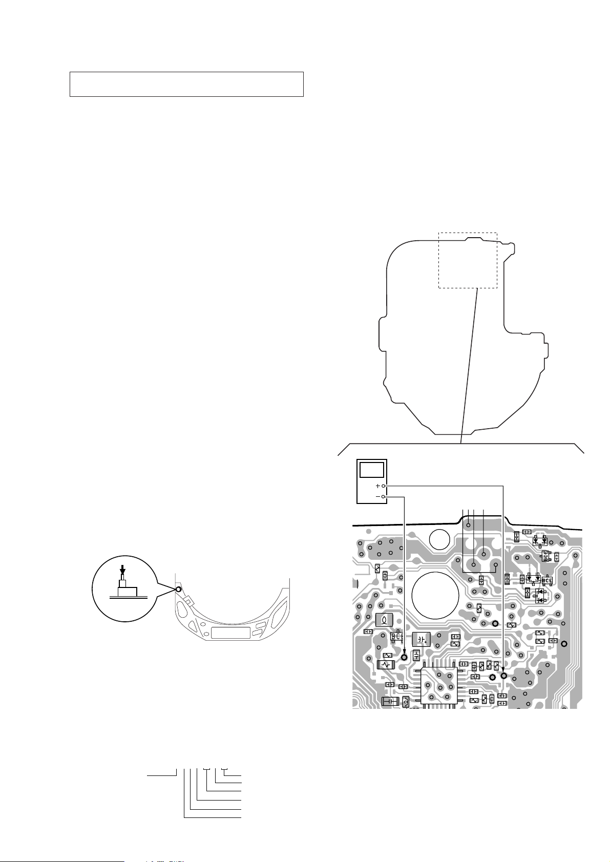
TP506
digital voltmeter
TP547
SERVICING NOTES
NOTES ON HANDLING THE OPTICAL PICK-UP BLOCK OR
BASE UNIT
The laser diode in the optical pick-up block may suffer electrostatic
breakdown because of the potential difference generated by the charged
electrostatic load, etc. on clothing and the human body. During repair,
pay attention to electrostatic breakdown and also use the procedure in
the printed matter which is included in the repair parts.
The flexible board is easily damaged and should be handled with care.
NOTES ON LASER DIODE EMISSION CHECK
The laser beam on this model is concentrated so as to be focused on the
disc reflective surface by the objective lens in the optical pick-up block.
Therefore, when checking the laser diode emission, observe from more
than 30cm away from the objective lens.
Before Replacing the Optical pick-up Block
Please be sure to check thoroughly the parameters as per the “Optical
pick-up Block Checking Procedure” (Part No. : 9-960-027-11) issued
separately before replacing the optical Pick-up block.
Note and specifications required to check are given below.
• FOK output : IC501 !™ pin
When checking FOK, remove the lead wire to disc motor.
• S curve P-to-P value : 0.9 – 1.5Vp-p IC501 #¡ pin. (Connect pin !™
of IC501 (TP880) and 3 of IC501 (GND) with a jumper wire).
When checking S curve P-to-P value, remove the lead wire to disc
motor.
• Adjusted part for focus gain adjustment : RV503
• RF signal P-to-P value : 0.8 – 1.2Vp-p
• Traverse signal P-to-P value : 1.0 – 2.4Vp-p
• The repairing grating holder is impossible.
• Adjusted part for tracking gain adjustment : RV502
5. Calculate the current value by the reading of the digital voltmeter.
Reading of the tester (V) ÷ 4.7 ( Ω ) = current value (A)
(Example) Reading of the digital voltmeter of 0.2256 V :
0.2256 V ÷ 4.7 Ω = 0.048 (A) = 48 mA
6. Check that the current value is within the following range.
• Current value of the label
+5
mA(25°C)
-11
Variation by temperature : 0.4mA / °C
Current increases with temperature increased.
Current decreases with temperature decreased.
If the current is more than the range above, there is a trouble in the
automatic power control circuit or the laser diode is in deterioration.
If less than the range, a trouble exists in the automatic power control
circuit or the optical pick-up.
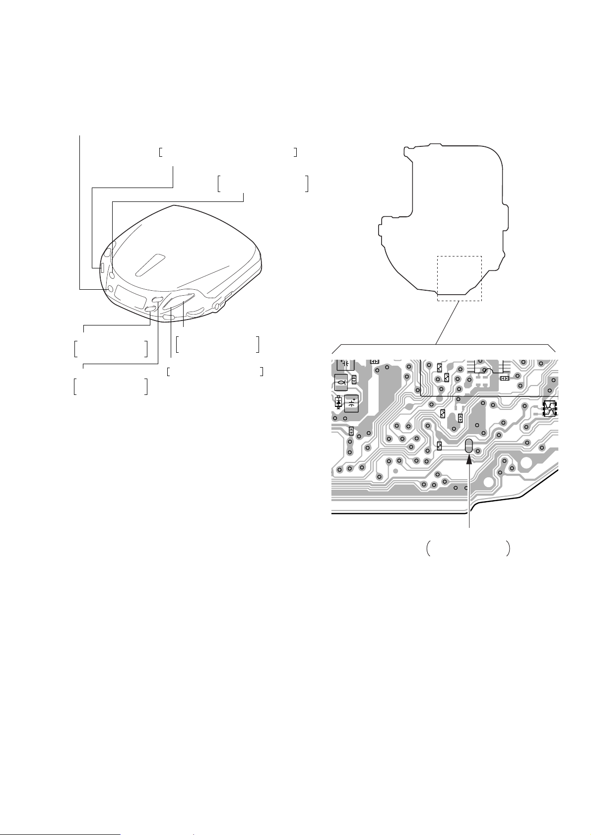
[MAIN BOARD] (Side B)
Laser Diode Checking Methods
During normal operation of the equipment, emission of the laser diode
is prohibited unless the upper panel is closed while turning ON the S801
(push switch type).
The following two checking methods for the laser diode are operable.
Method-1 (In the service mode or normal operation) :
Emission of the laser diode is visually checked.
1. Open the upper lid.
2. Push the S801 as shown in Fig. 1-1 .
3. Check the object lens for confirming normal emission of the laser
diode. If not emitting, there is a trouble in the automatic power
control circuit or the optical pick-up. During normal operation, the
laser diode is turned ON about 2.5 seconds for focus searching.
S801
Fig.1-1 Method to push S801
Method-2 (In the service mode or normal operation) :
Check the value of current flowing in the laser diode.
1. Remove the upper panel.
2. Read the current printed on the rear side of the optical pick-up.
(Print on the rear side of the optical pick-up)
3. Connect a level meter as shown in Fig. 1-2
4. Press the ^ key.
AC2211397
current value
A : less than 48 mA
year
month
date
shift No.
line No.
version
C516
R807
R510
C511
R505
C520
L502
C506
Q501
TP523
C512
TP306
TP547
C517
1
5
8
C525
TP534
32 30
R517
IC501
C514
25
TP521
TP512
C599
TP503
TP509
24
20
17
C208
C505
R521
C598
TP102
TP302
TP514
(TEO)
TP502
R502
C503
8
TP202
TP522
R503
R504
TP513
(RFO)
FB101
FB302
R519
TP511
C510
FB201
TP515
TP506
C513
C205
TP508
TP507
C108
D804
TP540
D105
Q101
Q201
R512
R501
TP504
D205
C501
Fig. 1-2 Digital Voltmeter Connecting Location
C105
TP533
(VC)
– 3 –
LOCATION AND FUNCTION OF CONTROLS
SECTION 2
GENERAL
1234 5 7 8
6
p ^
90!¡!™!£!¢!∞!§!¶
1 ESP (Electronic Shock Protection) button
2 OPEN button
3 DC IN 4.5V jack
4 PLAY MODE button
5 + FF button
6 LINE OUT jack
7 p STOP button
8 ^ Play/pause button
9 OFF-RESUME-ON switch
Remote control : (D-E455/E459CK)
+ p (stop)
Earphones
0 2 /REMOTE jack
!¡ AVLS switch
!™ ∑ VOLUME control
!£ SOUND button
!¢ = FR button
!∞ Information display panel
!§ REPEAT/ENTER button
!¶ HOLD switch
HOLD**
+ = (AMS*/search)
Remote control
*
Automatic Music Sensor
**
When you are not using the remote
control, slide HOLD in the direction of the
arrow to prevent any accidental operation.
To unlock, slide HOLD back.
Note
• Use onl y the supplied remote contr ol. Y ou
cannot operate this player with the remote
control supplied with other models.
+ ( (play)
+ + (AMS*/search)
VOL (volume)
– 4 –
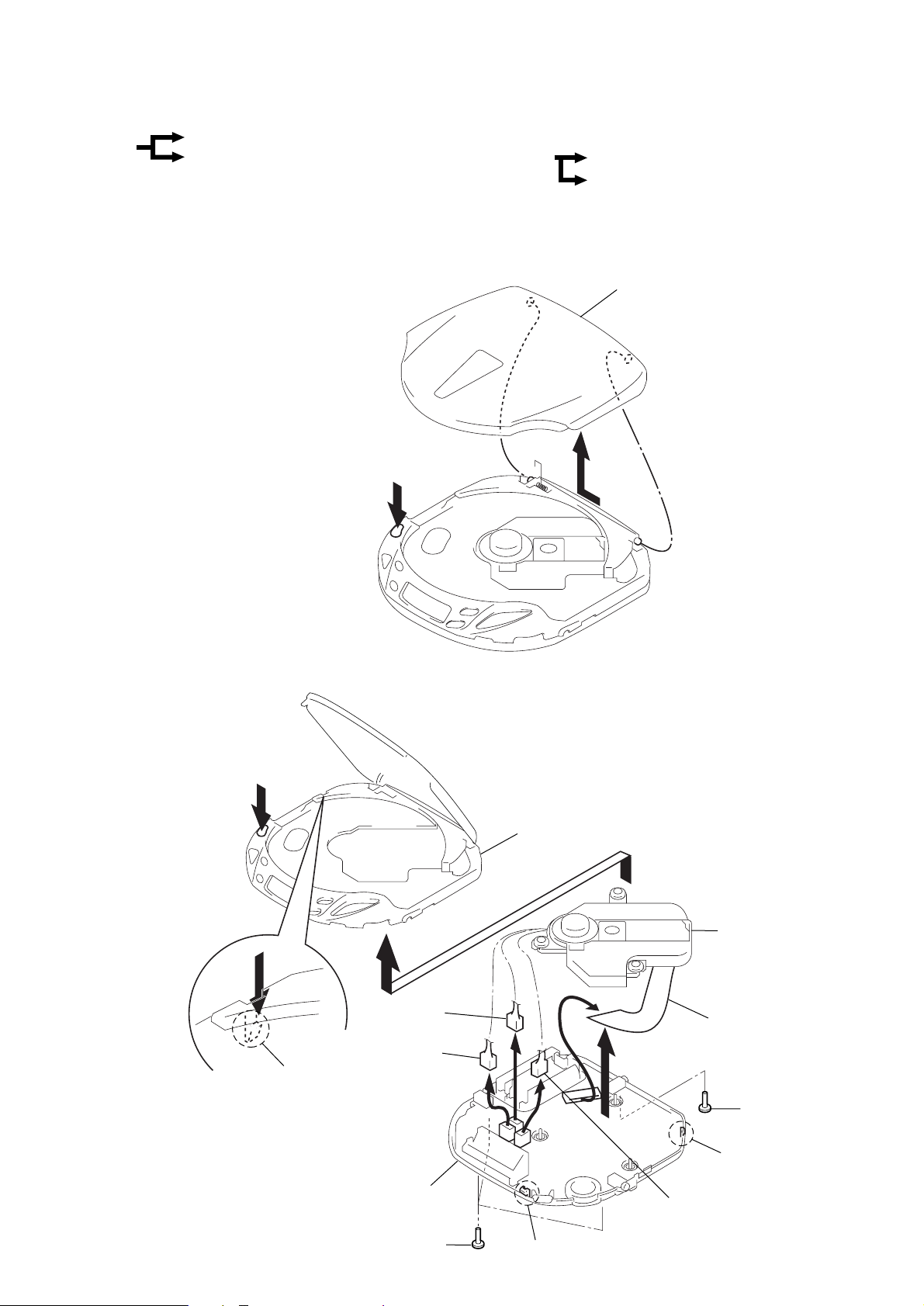
SECTION 3
DISASSEMBLY
r
The equipment can be removed using the following procedure.
Set
Note : Follow the disassembly procedure in the numerical order given.
3-1. LID ASSY, UPPER
Lid ASSY, Upper
Cabinet (Upper) ASSY, Cabinet (Lower) sub ASSY, MD ASSY
1
OPEN
Main board, LED sub board (E456CK, E459CK)
Turn table motor ASSY (Spindle) (M902),
Optical pick-up (DAX-11E),
Sled motor ASSY (M901)
Lid ASSY, Upper
2
3-2. CABINET (UPPER) ASSY, CABINET (LOWER) SUB ASSY, MD ASSY
2
OPEN
Cabinet (Upper) ASSY
5
3
8
CN702
7
CN701
Claw
6
MD ASSY
!º
CN501
1
(1.4x2.5)
Screw
Cabinet (Lower) sub
ASSY
1
Screws (1.4x2.5)
– 5 –
4
Claw
9
CN703
4
Claw
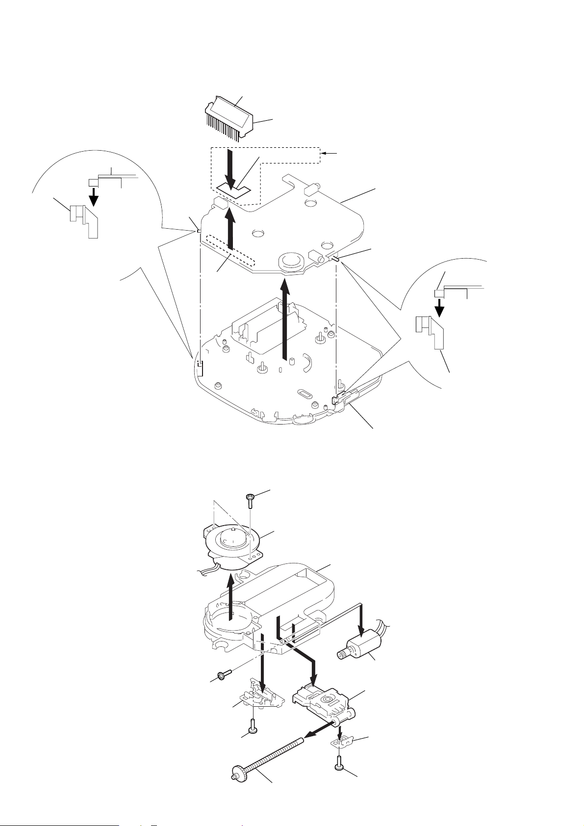
3-3. MAIN BOARD, LED SUB BOARD (E456CK, E459CK)
)
LCD801
Holder (LCD)
S804
Knob (HOLD)
To install, position the knob
and the switch respectively.
Sometime the HOLD switch
(S804) and RESUME switch
(S803) will be broken.
S804
4
3
2
Remove solder
LED sud board
1
E456CK, E459CK
Main board
S803
S803
Knob (RESUME
Cabinet (Lower) sub ASSY
3-4. TURN TABLE MOTOR ASSY (SPINDLE) (M902),
OPTICAL PICK UP (DAX-11E), SLED MOTOR ASSY (M901)
1
Screws (B1.7)
Turn table motor ASSY (Spindle) (M902)
2
4
9
Screws
(+P1.4x2.5)
Spring, sled
3
Screw (B1.7x6)
8
5
Chassis
!º
7
Sled motor ASSY
(M901)
Optical pick-up
(DAX-11E)
Rack
Screw ASSY, Feed
– 6 –
6
Screw
SECTION 4
L402
20
T802 (TEST)
Normal mode : Open
Test mode : Short
SERVICE MODE
Service Mode (service program)
The equipment is provided with a service program built in the microcomputer, like conventional models.
Service program operation methods are described in the following.
REPEAT/ENTER
Tracking gain-up mode while pressing
HOLD OFF n ON
Be sure to turn OFF the HOLD switch
(if ON, pressing each key is deactivated)
PLAY MODE
Tracking servo and sled
servo are turned ON
p ^
^
=
(FR)
The optical pick-up
is moved inwardly
+
(FF)
The optical pick-up
is moved outwardly
(PLAY/PAUSE)
FOCUS is turned ON
to effect pull in mode
p
(STOP)
All servos are turned OFF
Fig. 4-1 Layout of each key
• Step 1 (Service mode setting method)
1. Turn OFF the HOLD switch the external power supply disconnected (power is not applied to the set).
2. Solder across the T802 (TEST) terminals (pin %™, IC801 (TEST)
is grounded).
3. Connect an external power supply.
Thus, the set is switched to the service mode.
• Step 3 (Resetting service mode )
1. Be sure to disconnect the external power supply and remove the
solder bridge at the TEST terminals connected in setting.
2. The set thus becomes available for normal operation.
– MAIN BOARD – (Side A)
R307
R308
TP862
R830
TP301
R808
24
C814
T802
(TEST)
C302
1
R
Q302
D407
C809
C407
C420
C417
TP857
• Step 2 (Operation in the service mode )
1. Once the service mode is effected, the LCD displays 5 indications each of which is repeatedly displayed.
However, the following operations can be activated even if LCD
indication is effected.
2. By pressing the + or = key, the optical pick-up movable
inwardly or outwardly. However, if this is activated, tracking
servo and sled servo are turned OFF, so it can be turned ON by
pressing the PLAY MODE key, if required.
3. By pressing the REPEA T/ENTER key , the tracking gain-up mode
becomes active.
4. By pressing the ^ key, focus is turned ON from focus searching while entering CLV-S (pull-in mode).
Without disc, focus searching is repeated continuously.
5. By pressing the PLAY MODE key, tracking servo, sled servo
and CLV-A (servo in PLAY) are turned ON.
6. When 4. and 5. are performed, playing begins. No muting is ON
in the service mode.
7. By pressing the p key, all servos (focus tracking and sled) are
turned OFF. However, the disc motor revolves for a while by
inertia.
Fig. 4-2 Location of test terminal
– 7 –
SECTION 5
RF level
0.8 – 1.2 Vp-p
ADJUSTMENTS
CD SECTION
Precautions for Adjustment
1. Before beginning adjustment, set the equipment to service mode.
After the completion of adjustment, be sure to reset the service
mode.
For more information, see “Service Mode (service program)”
on page 7.
2. Perform adjustments in the order given.
3. Use the disc (YEDS-18. Part No. 3-702-101-01) unless otherwise indicated.
4. Power supply voltage requirement : DC 4.5 V
HOLD switch : OFF
VOLUME : Minimum
SOUND switch : NORM
AVLS switch : OFF
Before Beginning Adjustment
Set the equipment to service mode (See page 7) and check the following.
If there in an error, repair the equipment.
• Checking of the sled motor
1. Open the upper panel.
2. Press the + and = keys and check that the optical pick-up
can move smoothly without sluggishness or abnormal noise in
innermost periphery n outermost periphery n innermost periphery.
+ : The optical pick-up moves outwardly
= : The optical pick-up moves inwardly
• Checking of focus searching
1. Open the upper panel.
2. Press the ^ key. (Focus searching operation is activated continuously).
3. Check the object lens of the optical pick-up for smooth up/down
motion without sluggishness or abnormal noise.
4. Press the p key.
Check that focus searching operation is deactivated. If not, again
press the p key slightly longer.
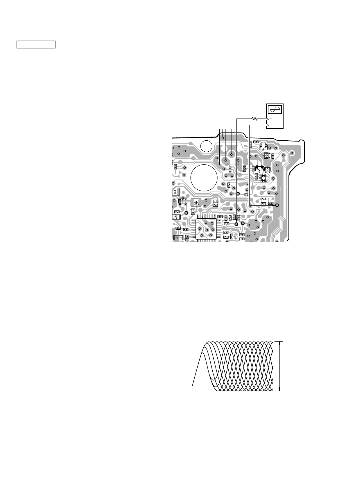
Focus Bias Check
Condition :
• Hold the set in horizontal state.
Procedure :
[MAIN BOARD] (Side B)
oscilloscope
(AC range)
2 k
Ω
07
0
505
1
C520
L502
C506
Q501
TP523
C512
TP306
TP547
C517
1
5
8
C525
32 30
TP513 (RFO)
C514
R517
TP512
TP534
25
IC501
TP521
C599
24
20
17
C208
TP503
TP509
C505
R521
C598
TP102
TP302
TP514
(TEO)
TP502
R502
C503
TP202
TP513
(RFO)
8
FB101
TP522
R503
R504
FB302
R519
TP511
FB201
TP515
TP506
C510
C513
TP533
(VC)
D105
C108
D804
C205
TP508
TP507
R512
R501
TP504
TP540
Q101
Q201
D205
C501
C105
TP533
(VC)
1. Set the equipment to service mode stop state (See page 7).
2. Connect the oscilloscope between TP513 (RFO) and TP533 (VC)
on the MAIN board.
3. Move the optical pick-up by Pressing the + and = keys.
4 Put the disc (YEDS-18).
5. Press the ^ key.
From focus searching, focus is turned ON while entering
( )
CLV drawing-in mode. Tracking and sled are turned OFF.
6. Press the PLAY MODE key. (Both tracking and sled are turned
ON).
7. Check the oscilloscope waveform is as shown below.
A good eye pattern means that the diamond shape (◊) in the center of the waveform can be clearly distinguished.
• RF Signal Reference Waveform (eye pattern)
To watch the eye pattern, set the oscilloscope to AC range and
increase the vertical sensitivity of the oscilloscope for easy watching.
8. Stop removing of the motor by pressing the p key.
9. After the completion of adjustment, reset service mode.
(See page 7 )
– 8 –
 Loading...