

Page 1

PRODUCT DESCRIPTION MANUAL
DDS-4 Tape Drive
Model : SDT-10000
: SDT-11000
Ver. 1.2 July, 1999
Sony Corporation
Page 2
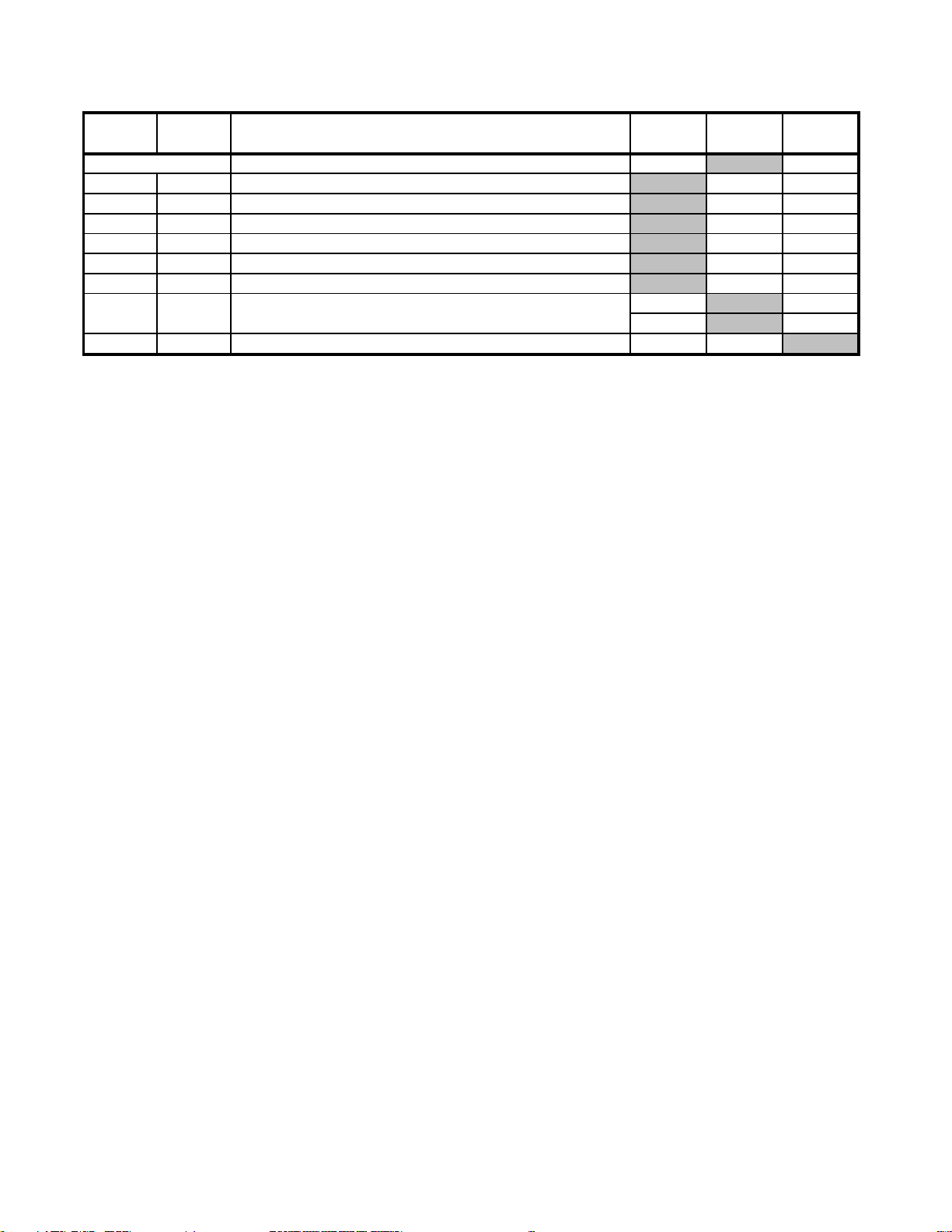
Difference List ( From Ver.1.1 To Ver.1.2 )
SDT-11000 SCSI Signals ( Low-Voltage-Differential
1-11Introduction
1-2
1.1
Feature of the drive
2-3
2.1.3
Connectors
2-3
2.13.1
SCSI Cables and Terminators
2-6
2.3.2.2
Burst Data Transfer Rate To and From the SCSI Bus
3-3/3-4
3.1.4
SCSI 68 Pin Connector
3-3
Table 3-1
SDT-11000 SCSI Signals ( Low-Voltage-Differential
Type Bus P Cable Signal Assignment)
7-8
Error Set 2
13h: DDS Controller SRAM TEST FAILURE
Model Name
Page Clause Title Modify Add Delete
Page 3
5
5
5
5
5
5
5
5
5
5
5
5
5
5
5
5
5
5
5
5
5
5
5
5
5
5
5
5
5
5
5
5
5
5
5
5
5
5
5
5
5
5
5
5
5
5
5
5
5
1. Introduction
234
234
234
234
234
234
234
2. Specification
3. Installation
4. Operation
5. SCSI Interface
6. Command Specificaiton
7. Drive Diagnostics
234
234
234
234
234
234
234
234
234
234
234
234
234
234
234
234
234
234
234
234
234
234
234
234
234
234
234
234
234
234
234
234
234
234
234
234
234
234
234
234
234
234
APPENDIX
Page 4

1. INTRODUCTION
12345
1
5
1
5
1
5
1
5
1
5
1
5
1
5
12345
1 INTRODUCTION ............................................................................................................. 1-1
1. 1 Features of the drive ........................................................................................ 1-2
1. 2 Reference ......................................................................................................... 1-3
234
234
234
234
234
234
234
Page 5

1. Introduction
1. INTRODUCTION
This manual provides information about the Sony SDT-10000/SDT-11000 Digital Data Storage (DDS) Tape Drives
which is necessary to integrate the drives into OEM products.
This manual describes the specifications, SCSI Interface, diagnostics, operation and installation of Sony DDS Tape
Drives. This drive is:
• SDT-10000/SDT-11000 20 to 40 GB capacity, 2.36 to 4.72 MBytes/Second Transfer Rate, Ultra/WIDE, Singleended or Low Voltage differential, 3.5"FH
*1, *2 This is assuming 2:1 Compression ratio.
The degree of data compression attained while recording data varies according to system environment and data
type.
Note: The SDT-10000/SDT-11000 drive uses data compression to achieve high capacity and high transfer rates. Ac-
tual capacity and transfer rate depends on the source file type.
Note: The capacity ratings listed above are based on a 150 meter DDS-4 tape cassette.
The Sony SDT-10000/SDT-11000 drive is a high capacity data storage device using 4 mm DAT (Digital Audio Tape)
technology. The SDT-10000/SDT-11000 drive achieves high data reliability through read-after-write, an additional
level of Error Correction Code, and other features.
The Sony SDT-10000/SDT-11000 drive stores data on tape using a standard format called DDS (Digital Data Storage),
DDS-DC, DDS-2, DDS-3 and DDS-4. This format is used by numerous other DDS tape drive manufacturers, providing
a broad range of compatible tape drives.
The Sony SDT-10000/SDT-11000 is fully READ and WRITE compatible with the DDS-4, DDS-3, DDS-2, DDS and
DDS-DC format tapes.
*1
*2
SONY SDT-10000/SDT-11000 DDS Tape Drive
1 - 1
Page 6

1. Introduction
1.1 FEATURES OF THE DRIVE
Major features of the Sony SDT-10000/SDT-11000 include:
• 20 GB capacity
• Sustained transfer rate - 2,360 KB/sec
• Supported Format: DDS-4, DDS-3, DDS-2, DDS , DDS-DC and DCLZ
• Fully READ and WRITE compatible with the DDS-4, DDS-3, DDS-2, DDS and DDS-DC format tapes
• Burst transfer rate
• Large 10 MB Buffer
• 3 1/2 inch form factor
• Embedded SCSI interface (Ultra/WIDE, Single-ended or Low Voltage differential)
• Supports Variable or Fixed record length
• Supports SCSI Disconnection/Arbitration
• Read After Write (RAW)
• Frame rewrite function
• Three levels of Error Correction Code (ECC)
• High Speed search (100 times normal Read/Write speed)
• Random read
• N-Group write option (DDS-2, DDS and DDS-DC only)
• Dual Partition option
(20GB to 40 GB with Data Compression) *1
(approximately 2.36 MB/s to 4.72 MB/s with Data Compression) *2
*1, *2 This is assuming 2:1 Compression ratio.
The degree of data compression attained while recording data varies according to system environment
and data type.
- 14 MB/sec Asynchronous
- 40 MB/sec Synchronous
1 - 2
SONY SDT-10000/SDT-11000 DDS Tape Drive
Page 7

1. Introduction
1.2 REFERENCE
Please refer to the following documents for additional information:
• Helical-Scan Digital Computer Tape Cartridge for Information Interchange (3.81 mm (0.150 in) Digital Data Stor-
age (DDS) Recorded Format)
ANSI X3.203
• Proposed Final Test Unrecorded Helical-Scan Digital Computer Tape Cartridge
ANSI ASC TC X3B5 Document 92-251
• 3,81 mm Wide Magnetic Tape Cartridge For Information Interchange
Helical Scan Recording, DDS Format, June 1990
European Computer Manufacturers Association (ECMA-139)
1
• 3,81 mm Wide Magnetic Tape Cartridge For Information Interchange
Helical Scan Recording, DDS-DC Format, June 1991
European Computer Manufacturers Association (ECMA-150)
1
• Data Compression For Information Interchange
Adaptive Coding with Embedded Dictionary, DCLZ Algorithm, June 1991
European Computer Manufacturers Association (ECMA-151)
1
• 3.81mm Wide Magnetic Tape Cartridge For Information Interchange
Helical Scan Recording, DDS-2 Format Using 120m Length Tapes,
December 1993
European Computer Manufacturers Association (ECMA-198)
1
• 3.81mm Wide Magnetic Tape Cartridge For Information Interchange
Helical Scan Recording, DDS-3 Format Using 125m Length Tapes
European Computer Manufacturers Association(ECMA XXX)
1
• Designing a Data Storage Format for Digital Audio Tape (DAT)
DDS Manufacturers Group
• Small Computer System Interface (SCSI-1), ANSI X3.131-1986
The ANSI authorized standard for SCSI implementation, available through ANSI
2
• Enhanced Small Computer Systems Interface (SCSI-2)
ANSI X3T9.2/86-109 (Revision 10H, or above), available through ANSI
2
• Parallel Small Computer Systems Interface (SCSI-3)
ANSI X3T10/855D (Revision 15a, or above) available through ANSI.
Note 1: Also available from: European Computer Manufacturers Association
114 Rue du Rhone - CH-1204 Geneva(Switzerland)
TEL: (41) 22-735-36-34
FAX: (41) 22-786-52-31
Note 2: Also available from: Global Engineering Documents
2805 McGaw Avenue
Irvine, CA 92714
(800) 854-7179
(714) 261-1455
SONY SDT-10000/SDT-11000 DDS Tape Drive
1 - 3
Page 8

2. SPECIFICATION
5
5
5
5
5
5
5
2. 1 PHYSICAL SPECIFICATIONS ................................................................................. 2-1
2. 1. 1 Dimensions .................................................................................................. 2-1
2. 1. 2 Weight........................................................................................................... 2-3
2. 1. 3 Connectors................................................................................................... 2-3
2. 2 ENVIRONMENTAL SPECIFICATIONS .................................................................... 2-4
2. 2. 1 Temperature and Humidity Range ............................................................. 2-4
2. 2. 2 Altitude ......................................................................................................... 2-4
2. 2. 3 Dust............................................................................................................... 2-4
2. 2. 4 Vibration ....................................................................................................... 2-4
2. 2. 5 Shock............................................................................................................ 2-4
2. 2. 6 Acoustic Noise............................................................................................. 2-5
2. 2. 7 ESD ............................................................................................................... 2-5
2. 2. 8 Orientation ................................................................................................... 2-5
2. 3 PERFORMANCE SPECIFICATION.......................................................................... 2-6
2. 3. 1 Data Capacity............................................................................................... 2-6
2. 3. 2 Data Transfer Rate....................................................................................... 2-6
2. 3. 3 Initialize Time ............................................................................................... 2-6
2. 3. 4 Load Time..................................................................................................... 2-7
2. 3. 5 Rewind Time ................................................................................................ 2-7
2. 3. 6 Search Time ................................................................................................. 2-7
2. 3. 7 Unload Time ................................................................................................. 2-7
2. 3. 8 Error Rate ..................................................................................................... 2-7
2. 3. 9 Retry Limits on Rewrites ............................................................................ 2-7
2. 3. 10 Definition of Failure................................................................................... 2-7
2. 3. 11 Mean Time Between Failures ................................................................... 2-7
2. 3. 12 Mean Time To Repair ................................................................................ 2-7
2. 3. 13 Component Life ......................................................................................... 2-8
2. 3. 14 Durability .................................................................................................... 2-8
2. 4 SAFETY...................................................................................................................... 2-8
2. 4. 1 Conditions of Acceptability ........................................................................ 2-8
2. 5 INSTALLATION REQUIREMENTS .......................................................................... 2-9
2. 5. 1 Power Requirements................................................................................... 2-9
2. 1. 1. 1 Mounting Holes .......................................................................... 2-2
2. 1. 3. 1 SCSI Cables and Terminators................................................... 2-3
2. 3. 2. 1 Sustained Data Transfer Rate To and From Tape ................... 2-6
2. 3. 2. 2 Burst Data Transfer Rate To and From the SCSI Bus ............ 2-6
234
234
234
234
234
234
234
Page 9
2. SPECIFICATION
2. SPECIFICATIONS
Physical, environmental and performance specifications for the SDT-10000/SDT-11000
2. 1 PHYSICAL SPECIFICATIONS
2. 1. 1 Dimensions
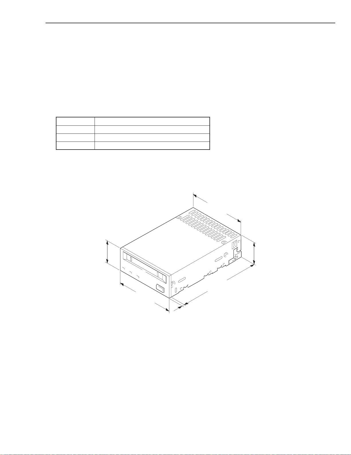
The SDT-10000/SDT-11000 conforms to the 3.5 inch standard height form factor.
SDT-10000/SDT-11000
Height 41.2 mm (1.62 in) ± 0.5 mm (0.02 in)
Width 101.6 mm (4.0 in) ± 0.5 mm (0.02 in)
Depth 146.0 mm (5.75 in) ± 0.5 mm (0.02 in)
Note: The above dimensions do not include the front panel thickness, eject button and some projecting.
41.2±0.5 mm
(1.62 inch)
101.6±0.5 mm
(4.00 inch)
101.6±0.5 mm
146±0.5 mm
3.8±0.5 mm
(0.15 inch)
SDT-10000/SDT-11000
Figure 2-1 Dimensions
(4.00 inch)
(5.75 inch)
41.2±0.5 mm
(1.62 inch)
SONY SDT-10000/SDT-11000 DDS Tape Drive
2 - 1
Page 10
2. SPECIFICATION
2. 1. 1. 1 Mounting Holes
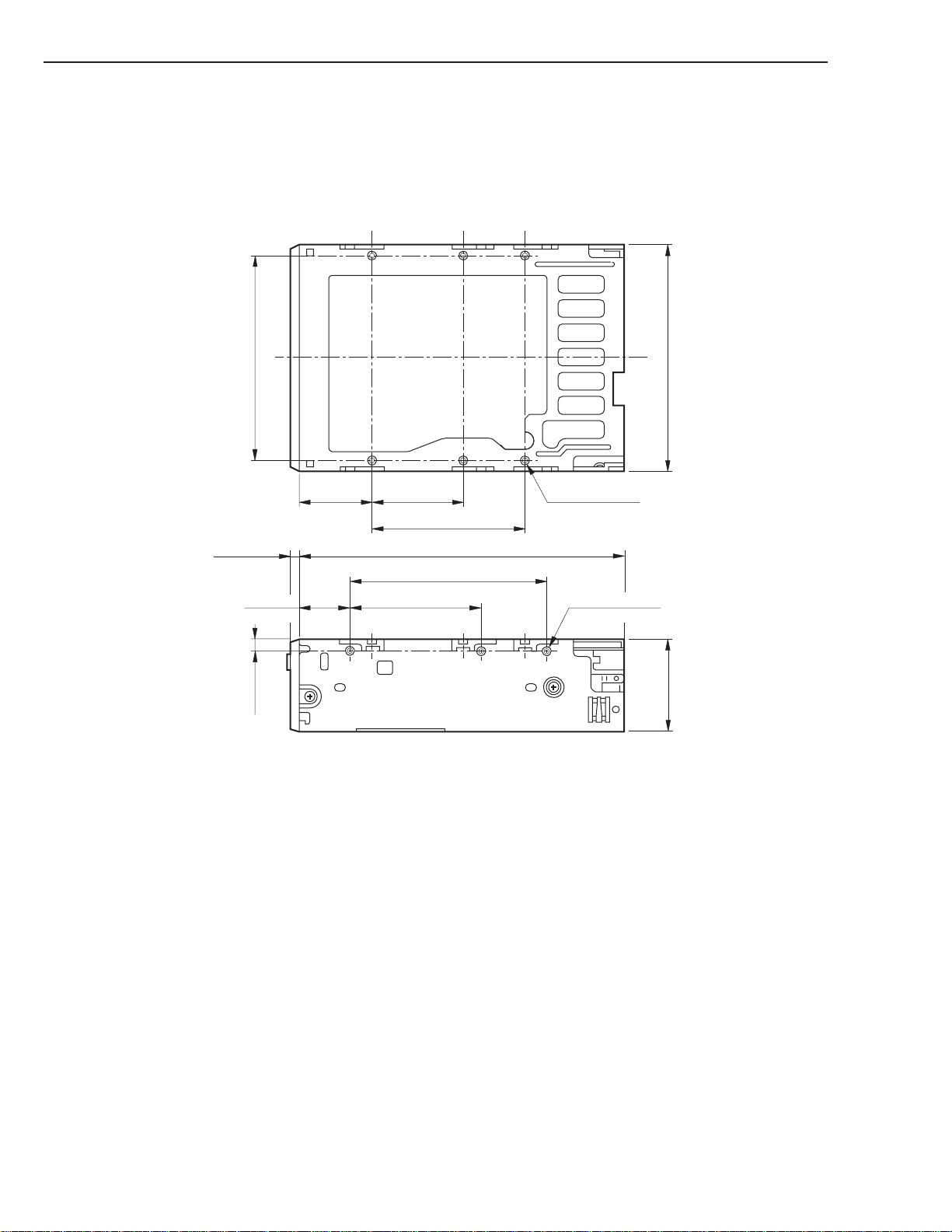
Figure 2-2 gives details of the mounting holes for the drive.
94 ± 0.3 mm
3.8 ± 0.5 mm
(0.15 in)
21 ± 0.3 mm
(0.83 in)
5 ± 0.3 mm
(3.70 in)
(0.20 in)
31 ± 0.3 mm
(1.22 in)
42 ± 0.3 mm
(1.65 in)
70 ± 0.3 mm
(2.76 in)
146 ± 0.5 mm
(5.75 in)
90 ± 0.3 mm
(3.45 in)
60 ± 0.3 mm
(2.36 in)
SDT-10000/SDT-11000
Figure 2-2 Mounting Holes
6-M3 (DEPTH 3mm)
(DEPTH 0.12 in)
3-M3 (DEPTH 3mm)
(DEPTH 0.12 in)
(4.00 in)
101.6 ± 0.5 mm
(1.62 in)
41.2 ± 0.5 mm
2 - 2
Note: Mounting Screw Thread Length 2.5 mm. If the mounting screw thread length is exceeded, damage to the drive
may occur.
SONY SDT-10000/SDT-11000 DDS Tape Drive
Page 11
2. SPECIFICATION
2. 1. 2 Weight
• SDT-10000/SDT-11000 - 600 grams (1 lb 5 oz), without a cassette
2. 1. 3 Connectors
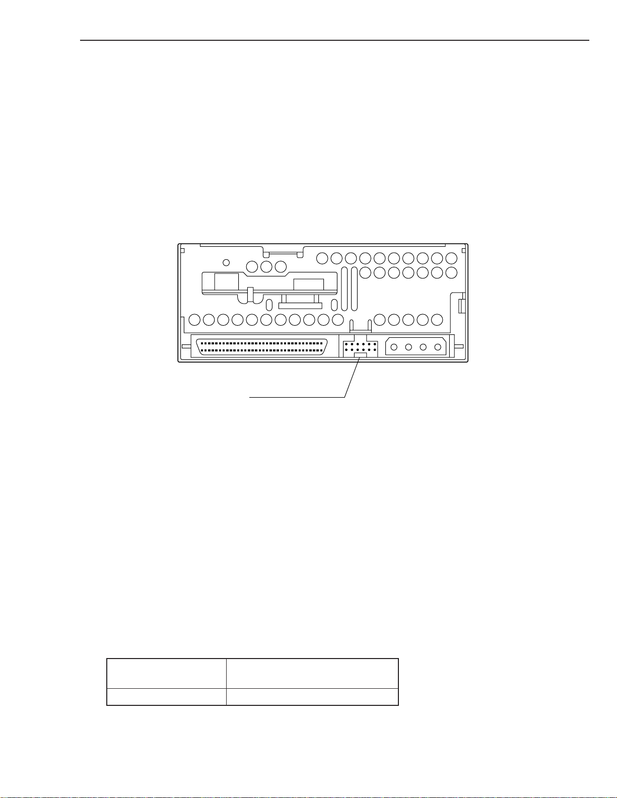
The SDT-10000/SDT-11000 has a SCSI connector with a power connector at the positions shown in Figure 2-3. All
other connectors are for use by Sony’s manufacturing and service facilities only.
SCSI & Power Connector
SDT-10000/SDT-11000
Figure 2-3 Connector Positions
2. 1. 3. 1 SCSI Cables and Terminators
The Single-Ended SCSI configuration is supported by SDT-10000 and SDT-11000.
The Low-Voltage-Differential SCSI configuration is supported by SDT-11000. The hardware specification of this interface can be found in Clause 3. Physical Characteristics, of the X3T10/1142D (SCSI Parallel Interface2) standard. Only
unshielded connectors are supported. Possible cable and connector sources are listed below. This does not imply that
these are the only sources for SCSI accessories.
Note: When using high speed data transfer with the SDT-10000/SDT-11000, it is recommended that total length of the
SCSI data cable not exceeded 1.5m for Single Ended SCSI configuration. As for Low-Voltage-differential SCSI
configuration for SDT-11000, less than 12m is recommended.
Cable 30 AWG Ribbon
Hitachi UL 20818 (or equivalent)
Connector AMP 1-786090-7 (or equivalent)
SONY SDT-10000/SDT-11000 DDS Tape Drive
2 - 3
Page 12

2. SPECIFICATION
2. 2 ENVIRONMENTAL SPECIFICATIONS
Note: The specifications which apply when a medium is present may be different than these.
2. 2. 1 Temperature and Humidity Range
Temperature
Operating: 5°C to 40°C ( T<10°C/h)
Non-operating(mech): -40°C to 70°C ( T<20°C/h)
Non-operating(tape): -40°C to 45°C ( T<20°C/h)
Humidity
Operating: 20 to 80% RH, non-condensing
Non-operating(mech): 5 to 95% RH ( RH<30%/h)
Non-operating(tape): 20 to 80% RH ( RH<30%/h)
Maximum wet bulb temperature=26°C
2. 2. 2 Altitude
Operating: 0 to 2133 m (0 to 7000 feet)
2. 2. 3 Dust
Operating: Less than 150 microgram/m
Based Sampling period 24 hours
2. 2. 4 Vibration
Operating: Swept Sine 5 to 500 Hz
@ 0.25 G Peak 1 Octave/min.
3 axis, 3 directions
Non-operating: Swept Sine 5 to 500 Hz
@ 0.5 G Peak 1 Octave/min.
3 axis, 3 directions
2. 2. 5 Shock
Operating: No Data Loss
Half Sine
5 G Peak 3 ms
3 axes, 3 directions
Interval 10 seconds
3
2 - 4
Non-operating: No Device Damage
Half Sine
90 G Peak 3 ms
(30 G Peak 11 ms)
3 axes, 3 directions
SONY SDT-10000/SDT-11000 DDS Tape Drive
Page 13
2. SPECIFICATION
2. 2. 6 Acoustic Noise
The ambient noise level is no greater than 25db (A). The sound-meter on (A) scale is located 1m in front of the center
of the unit front panel.
Streaming Write/Read 35 db (A)
Insert/Eject 60 db (A)
(A): A curve weight
2. 2. 7 ESD
Discharge Voltage
Less than 15kV: No operation failure
Less than 20kV: No drive damage
2. 2. 8 Orientation
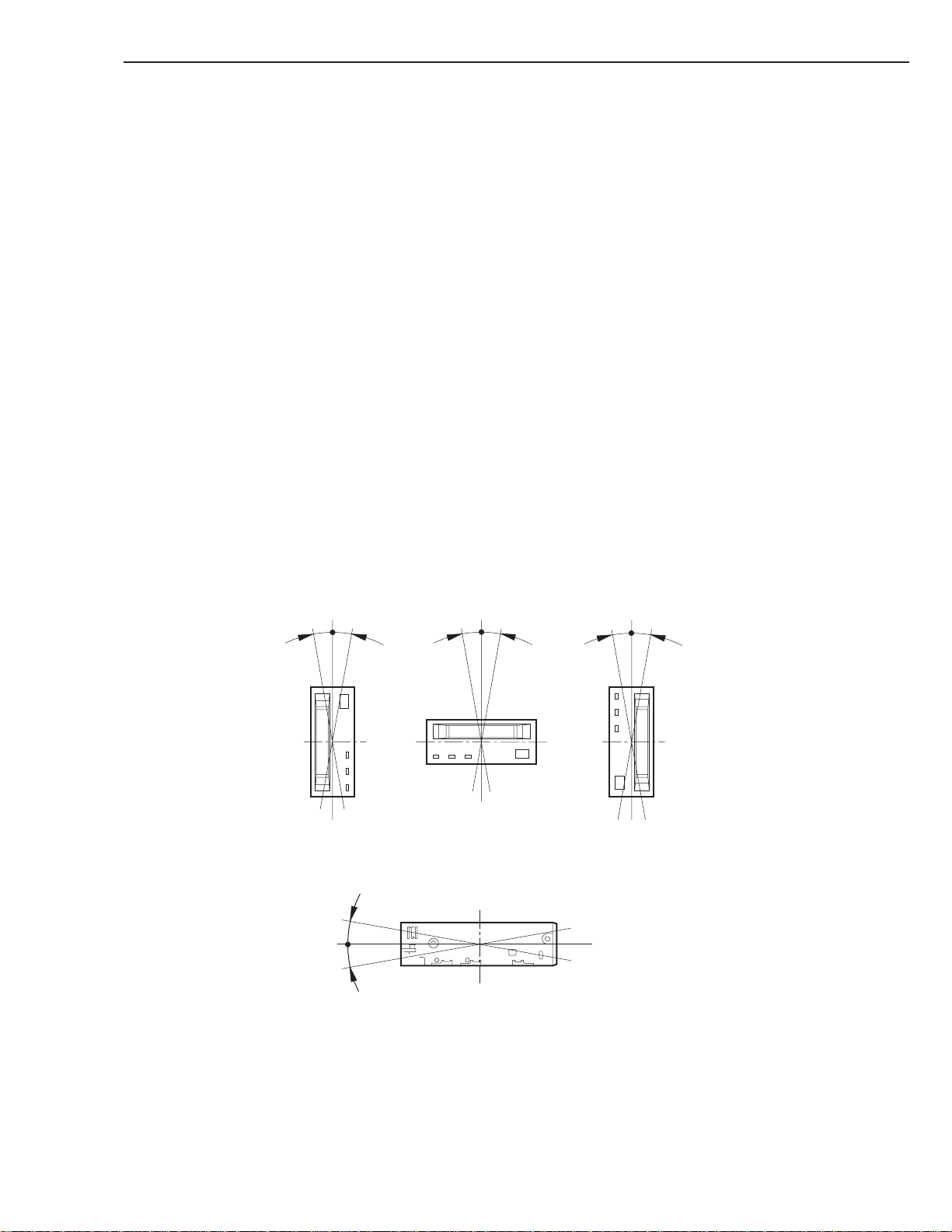
The SDT-10000/SDT-11000 can be installed in three different mounting positions as shown in the figure below. Each
position has a maximum tolerance of +/– 10 degrees.
10°10
°
10
°
10
10°10
°
°
10°10
°
Figure 2-4 Mounting Attitude and Tolerance
SONY SDT-10000/SDT-11000 DDS Tape Drive
2 - 5
Page 14

2. SPECIFICATION
2. 3 PERFORMANCE SPECIFICATION
The data capacity, data transfer rate and data reliability specifications in this chapter require the media to conform to the
DDS-4 Media Specification and also require the drive and media to remain within their respective operating and nonoperating environmental specifications. The specifications below also assume that the C3 ECC frame is generated on
writing and used as necessary on reading, and further assumes that read-after-write rewrites are used as necessary on
writing.
2. 3. 1 Data Capacity
The native (uncompressed) capacities of different length cartridges are as follows. Note that 60 m and 90 m cartridges
are automatically written in DDS-1 format, only 120 m cartridges are written in DDS-2 format, and only 125 m cartridges are written in DDS-3 format, and only 150 m cartridges are written in DDS-4 format
Length Format Native Capacity
60 m DDS-1 1.3 GB typical
90 m DDS-1 2.0 GB typical
120 m DDS-2 4.0 GB typical
125 m DDS-3 12.0 GB typical
150 m DDS-4 20.0 GB typical
The SDT-10000/SDT-11000 includes a data compression capability. When data compression is enabled that the drive
capacity can increase typically twice. The efficiency of the data compression depends on the actual data that is being
compressed and cannot be predicted precisely prior to compression.
Sustained transfer rate
Format W/O Compression W/Compression *1
DDS-1 778 KB/S 1556 KB/S
DDS-2 778 KB/S 1556 KB/S
DDS-3 2360 KB/S 4720 KB/S
DDS-4 2360 KB/S 4720 KB/S
2. 3. 2 Data Transfer Rate
2. 3. 2. 1 Sustained Data Transfer Rate To and From Tape
The sustained transfer rates to and from the tape are as follows. For this sustained rate to be achieved, the drive must be
streaming. There may be some dependency on the host for this to be achieved.
*1 This is assuming 2:1 Compression ratio.
The degree of data compression attained while recording data varies according to system environment and data type.
2. 3. 2. 2 Burst Data Transfer Rate To and From the SCSI Bus
The SDT-10000/SDT-11000 will transmit and receive data bursts to and from the SCSI bus at a maximum burst rate of
14 megabytes per second, using WIDE SCSI asynchronous transfers and 40 megabytes per second, using WIDE SCSI
synchronous transfers.
2 - 6
2. 3. 3 Initialize Time
Initialize Time means the period from the time the drive is powered on to the time when the drive is ready and waiting
for a SCSI command such as INQUIRY or TEST UNIT READY.
Initialize Time is less than 1 seconds.
Note: The drive will respond with BUSY status until the completion of the Initialize Time.
Note: The Initialize Time does not include the time necessary for drive diagnostics to complete and the drive to become
ready for tape insertion.
SONY SDT-10000/SDT-11000 DDS Tape Drive
Page 15

2. SPECIFICATION
2. 3. 4 Load Time
Load Time means the period from the time when the operator inserts a cassette into the drive to the time when the drive
is ready.
Load Time is less than 24 seconds (for a single partition tape).
2. 3. 5 Rewind Time
Rewind Time means the period from the beginning to the end of rewinding sequence. This value depends on the tape
length and the position of the head along the tape.
Rewind Time is less than 80 seconds, when a 150 meter tape is loaded.
2. 3. 6 Search Time
Search Time means the period for the drive to find the position that is required by a command. This time also depends
on the tape length and the position of the head along the tape.
Search Time is less than 90 seconds, when a 150 meter tape is loaded.
2. 3. 7 Unload Time
Unload Time means the period from the beginning of the unload sequence caused by Unload Command or Eject button
to the time when a cassette is ejected from the slot.
Unload Time does not include Rewind time.
Unload Time is less than 20 seconds (for a single partition tape).
2. 3. 8 Error Rate
The uncorrectable bit error rate is expected to be less than 10
-15
. For further details, refer to “Designing a Data Storage
Format for Digital Audio Tape (DAT)”, produced by the DDS Manufacturers Group.
2. 3. 9 Retry Limits on Rewrites
For Read-After-Write error correction, each frame can be rewritten up to a maximum of 255 times giving 256 writes of
the frame. With N-Group writing, where every group is written a fixed number of times, the upper limit is 8.
N-Group writing is not supported by DDS-3 and DDS-4.
2. 3. 10 Definition of Failure
A failure is defined as any permanent malfunction of the drive that prevents the user from retrieving data from tape. This
includes failure to power up, failure to unload or eject a cassette, or failure to write and read data to and from the tape,
providing that both the drive and tape are being used within specification.
Faults are not considered failures when they are related to operator error, mishandling and abuse, system-related faults
(cabling problems, unsupported systems, operating software, and so on), no trouble found, and transportation damage.
2. 3. 11 Mean Time Between Failures
The Mean Time Between Failures (MTBF) for the SDT-10000/SDT-11000 is 250,000 power-on hours, assuming a duty
cycle of 40%, where:
Duty cycle = × 100
Tape Motion Time
Power-on Time
12.5% is assumed as a typical usage level.
2. 3. 12 Mean Time To Repair
The Mean Time To Repair (MTTR) of the SDT-10000/SDT-11000 is 30 minutes. Since at the field level the entire drive
is considered a Field Replaceable Unit (FRU) the time to replace the drive with a new one is less that 30 minutes.
SONY SDT-10000/SDT-11000 DDS Tape Drive
2 - 7
Page 16

2. SPECIFICATION
2. 3. 13 Component Life
The specified life of the SDT-10000/SDT-11000 is 8 years average.
The usage model for this specification is as follows.
3 hours tape pulling time per day
6 days usage per week
The SDT-10000/SDT-11000 is equivalent to 7,500 hours tape-pulling life.
2. 3. 14 Durability
The durability of the components in the SDT-10000/SDT-11000 will exceed the number of operations listed on the
following table:
Start/Stop 400,000 times
Reposition 3,000,000 times
Thread/Unthread 10,000 times
Load/Eject 10,000 times
2. 4 SAFETY
The SDT-10000/SDT-11000 conforms to the following safety standards:
• Underwriters Laboratories, Inc.
UL 1950 (Third Edition), Safety of Information Technology Equipment, Including Electrical Business Equipment.
• Canadian Standards Association
CSA-C22.2 No. 950 (CUL), Safety of Information Technology Equipment, Including Electrical Business Equipment.
• TUV
EN 60950: 1992 + A1 + A2 + A3 + A4 + A11 Safety of Information Technology Equipment, Including Electrical
Business Equipment.
• CE Mark
2. 4. 1 Conditions of Acceptability
The SDT-10000/SDT-11000 is for use only in equipment where the suitability of the combination has been determined
by an appropriate certification organization (for example, Underwriters Laboratories, Inc. or the Canadian Standards
Association in North America, and the British Standards Institution or Verband Deutscher Elektrotechniker in Europe).
Other considerations include the following:
1. An enclosure must be supplied to limit the operator’s access to live parts, to provide system stability, and to
furnish the drive with the necessary grounding integrity.
2. The necessary voltage supplies must be provided. These supplies are Extra Low Voltage SEC for UL and CSA,
or Safety Extra Low Voltage for BSI, VDE, and so on, of +5V and +12V DC.
2 - 8
SONY SDT-10000/SDT-11000 DDS Tape Drive
Page 17

2. SPECIFICATION
2. 5 INSTALLATION REQUIREMENTS
2. 5. 1 Power Requirements
SDT-10000/SDT-11000
Voltage
5V +/-5%
12V +/-10%
Max Ripple
100 mV p-p
100 mV p-p
Current
Maximum
(Load/Unload)
2.0 A
1.6 A
Typical
(Write/Read)
1.0 A
0.3 A
SONY SDT-10000/SDT-11000 DDS Tape Drive
2 - 9
Page 18

3. INSTALLATION
5
5
5
5
5
5
5
3. 1 SCSI Connection/Setting the SCSI ID ..................................................................... 3-1
3. 1. 1 SCSI ID Number Jumper ............................................................................. 3-2
3. 1. 2 Parity Enable Jumper.................................................................................. 3-2
3. 1. 3 Power Connector......................................................................................... 3-2
3. 1. 4 SCSI 68 pin Connector................................................................................ 3-3
3. 2 Option Switches (DIP Switch).................................................................................. 3-4
3. 2. 1 Termination Power Switch.......................................................................... 3-4
3. 2. 2 Data Compression ON switch .................................................................... 3-5
234
234
234
234
234
234
234
Page 19
3. Installation
3 INSTALLATION
3. 1 SCSI CONNECTION/SETTING THE SCSI ID
Pin 34
Pin 68
SCSI 68 pin connector (Non-Shielded)
SCSI ID
321
SCSI ID
0
P.E.
R.
0
35
1
power connector
4321
GND GND 12V5V
10
11
12
13
14
1
2
3
4
5
6
7
8
9
Parity Enable
Jumpers
Reserved
SCSI ID 3
Parity
Disable
Note :
SCSI ID 2
SCSI ID 1
Enable
SCSI ID 0
= CLOSE/Jumper
= OPEN/Jumper not installed
Don’t care
15
SONY SDT-10000/SDT-11000 DDS Tape Drive
3 - 1
Page 20

3. Installation
3. 1. 1 SCSI ID Number Jumper
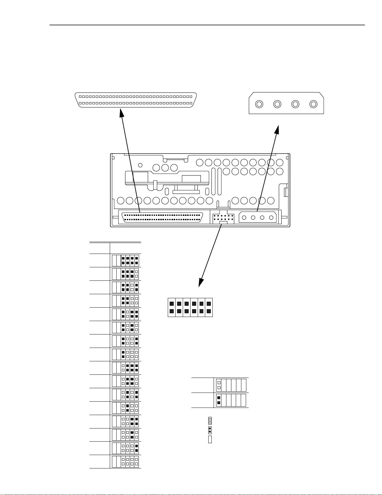
The SCSI ID number of the SDT-10000/SDT-11000 is selected by the SCSI ID number jumpers. The figure below
shows the jumper configuration for each of the possible SCSI IDs.
SCSI ID ID3 ID2 ID1 ID0
0 ::::
1 :::|
2 ::|:
3 ::||
4 :|::
5 :|:|
6 :||:
7 :|||
8 |:::
9 |::|
10 |:|:
11 |:||
12 ||::
13 ||:|
14 |||:
15 ||||
: = OPEN Jumper not installed
| = CLOSED Jumper installed
3. 1. 2 Party Enable Jumper
Parity check function can be disabled by jumper. Parity check is disabled while left end jumper is installed. Parity
generate function is always enabled.
Parity Setting
Enable |
Disable :
: = OPEN Jumper not installed
| = CLOSED Jumper installed
3. 1. 3 Power Connector
The power connector is illustrated as Figure 3-1
4321
3 - 2
GND GND 12V5V
Figure 3-1: Power Connector
SONY SDT-10000/SDT-11000 DDS Tape Drive
Page 21

3. Installation
3. 1. 4 SCSI 68 pin Connector
Figure 3-2 illustrates SCSI 68 pin connector, and table 3-1 shows the assignments for the pins of the connector.
Pin 34
Pin 68
1
35
Figure 3-2: Non-shielded SCSI Device Connector
SDT-11000 supports Low-Voltage-Differential SCSI configuration as shown table 3-1. SDT-10000 and SDT-11000
support Single-Ended SCSI configuration as shown table 3-2. SDT-11000 detects and switches SCSI configuration
between Low-Voltage-Differential and Signal-ended modes by monitoring DIFSENS signal assigned pin 16 SCSI bus.
(refer to table 3-1)
Table 3-1: SDT-11000 SCSI Signals (Low-Voltage-Differential Type BUS P Cable Signal Assignment)
Signal Name Cable Conductor Number Signal Name
-DB(12) 35 1 +DB(12)
-DB(13) 36 2 +DB(13)
-DB(14) 37 3 +DB(14)
-DB(15) 38 4 +DB(15)
-DB(P1) 39 5 +DB(P1)
-DB(0) 40 6 +DB(0)
-DB(1) 41 7 +DB(1)
-DB(2) 42 8 +DB(2)
-DB(3) 43 9 +DB(3)
-DB(4) 44 10 +DB(4)
-DB(5) 45 11 +DB(5)
-DB(6) 46 12 +DB(6)
-DB(7) 47 13 +DB(7)
-DB(P) 48 14 +DB(P)
GROUND 49 15 GROUND
GROUND 50 16 DIFFSENS
TERMPWR 51 17 TERMPWR
TERMPWR 52 18 TERMPWR
RESERVED 53 19 RESERVED
GROUND 54 20 GROUND
-ATN 55 21 +ATN
GROUND 56 22 GROUND
-BSY 57 23 +BSY
-ACK 58 24 +ACK
-RST 59 25 +RST
-MSG 60 26 +MSG
-SEL 61 27 +SEL
-C/D 62 28 +C/D
-REQ 63 29 +REQ
-I/O 64 30 +I/O
SONY SDT-10000/SDT-11000 DDS Tape Drive
3 - 3
Page 22

3. Installation
Table 3-2: SDT-10000/SDT-11000 SCSI Signals (Signal Ended Type BUS P Cable Signal Assignment)
Signal Name Cable Conductor Number Signal Name
-DB(8) 65 31 +DB(8)
-DB(9) 66 32 +DB(9)
-DB(10) 67 33 +DB(10)
-DB(11) 68 34 +DB(11)
Signal Name Cable Conductor Number Signal Name
-DB(12) 35 1 GROUND
-DB(13) 36 2 GROUND
-DB(14) 37 3 GROUND
-DB(15) 38 4 GROUND
-DB(P1) 39 5 GROUND
-DB(0) 40 6 GROUND
-DB(1) 41 7 GROUND
-DB(2) 42 8 GROUND
-DB(3) 43 9 GROUND
-DB(4) 44 10 GROUND
-DB(5) 45 11 GROUND
-DB(6) 46 12 GROUND
-DB(7) 47 13 GROUND
-DB(P) 48 14 GROUND
GROUND 49 15 GROUND
GROUND 50 16 GROUND
TERMPWR 51 17 TERMPWR
TERMPWR 52 18 TERMPWR
RESERVED 53 19 RESERVED
GROUND 54 20 GROUND
-ATN 55 21 GROUND
GROUND 56 22 GROUND
-BSY 57 23 GROUND
-ACK 58 24 GROUND
-RST 59 25 GROUND
-MSG 60 26 GROUND
-SEL 61 27 GROUND
-C/D 62 28 GROUND
-REQ 63 29 GROUND
-I/O 64 30 GROUND
-DB(8) 65 31 GROUND
-DB(9) 66 32 GROUND
-DB(10) 67 33 GROUND
-DB(11) 68 34 GROUND
3 - 4
SONY SDT-10000/SDT-11000 DDS Tape Drive
Page 23
3. Installation
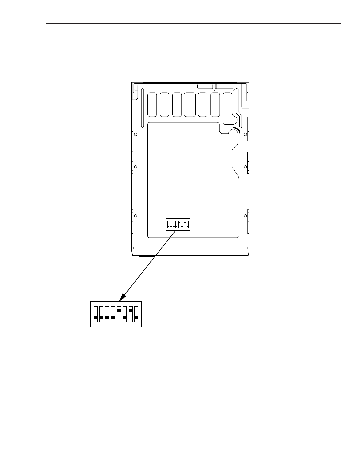
3. 2 OPTION SWITCHES (DIP SWITCH)
UNLOAD
N
O
1234567
3. 2. 1 Termination Power Switch
N
O
1234567
8
1 Reserved (OFF)
2 Reserved (OFF)
3 Reserved (OFF)
8
4 Reserved (OFF)
5 Terminator Power (ON)
6 Reserved (OFF)
7 DC Control-1 (ON)
8 DC Control-2 (OFF)
( ) …default setting
Position 5 of DIP switch is used to set whether SDT-10000/SDT-11000 provides the termination power to pin 17, 18, 51,
52 on SCSI bus, or not.
SONY SDT-10000/SDT-11000 DDS Tape Drive
3 - 5
Page 24

3. Installation
3. 2. 2 Data Compression ON switch
Data compression can be selected by DIP switch.
DC Control-1 DC Control-2
OFF OFF
OFF ON
ON OFF
ON ON
Table 3-2: Data Compression Switches
Definition
Compression disabled at power-on. The host is allowed to control
compression.
Compression disabled at power-on. The host is not allowed to control compression.
Compression enabled at power-on. The host is allowed to control
compression.
Compression enabled at power-on. The host is not allowed to control compression.
3 - 6
SONY SDT-10000/SDT-11000 DDS Tape Drive
Page 25

4. OPERATION
5
5
5
5
5
5
5
4. 1 SUMMARY OF LED INDICATIONS........................................................................... 4-1
4. 2 OPERATOR ACTION................................................................................................. 4-3
4. 3 INTERNAL FUNCTION ............................................................................................. 4-4
4. 4 TAPE FORMAT......................................................................................................... 4-7
4. 5 MAINTENANCE, TROUBLESHOOTING AND SERVICE ....................................... 4-8
4. 6 DATA COMPRESSION........................................................................................... 4-11
4. 2. 1 Powering up the SDT-10000/SDT-11000.................................................... 4-3
4. 2. 2 Inserting Cassettes ..................................................................................... 4-3
4. 2. 3 Removing Cassettes ................................................................................... 4-3
4. 2. 4 Write-Protecting Cassettes......................................................................... 4-3
4. 3. 1 The Load Sequence..................................................................................... 4-4
4. 3. 2 The Unload Sequence ................................................................................. 4-4
4. 3. 3 Power-Fail Handling .................................................................................... 4-4
4. 3. 4 Diagnostic and Normal Status Displays.................................................... 4-4
4. 3. 4. 1 Diagnostic Status Display ......................................................... 4-4
4. 3. 4. 1. 1 Front Panel Test.................................................... 4-5
4. 3. 4. 1. 2 Kernel Test ............................................................ 4-5
4. 3. 4. 2 Normal Status Display ............................................................... 4-6
4. 3. 4. 3 Media Warning............................................................................ 4-6
4. 4. 1 Tape Partitions............................................................................................. 4-7
4. 4. 1. 1 Formatting Partitions................................................................. 4-7
4. 5. 1 Head Cleaning.............................................................................................. 4-8
4. 5. 2 Troubleshooting Guide ............................................................................... 4-8
4. 5. 2. 1 Operational Problems ................................................................ 4-8
4. 5. 2. 2 Read/Write Problems ............................................................... 4-10
4. 5. 3 Clearance for Service................................................................................ 4-10
4. 5. 4 Packaging for Return to Sony .................................................................. 4-10
234
234
234
234
234
234
234
Page 26
4. OPERATION
4 OPERATION
4. 1 SUMMARY OF LED INDICATIONS
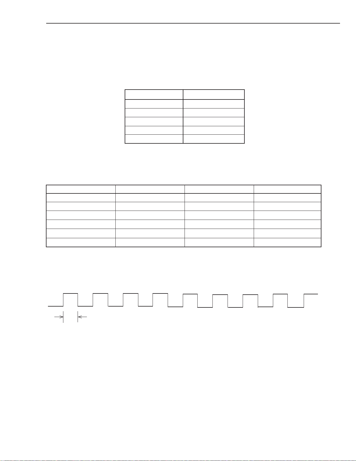
The SDT-10000/SDT-11000 LEDs have five (5) different methods of reporting the current status/operation of the drive:
LED function Meaning
Off Not active
On Activity
Flashing-1 Drive Activity
Flashing-2 Warning
Flash code 1, 2 Failure
Table 4-1: Possible LED indication meanings
The following table shows the meaning of each of the possible combinations of LED indications:
LED Busy Tape Status
Off Not Busy Unloaded
On SCSI active Loaded Write Protected
Flashing-1 Drive active Loading/Unloading Cleaning Tape at EOM
Flashing-2 Error Rate Warning Cleaning Request
Flash code 1 Waiting for Reset Waiting for Eject
Flash code 2 Illegal FW Tape Selftest Failure
Table 4-2: Meaning of each LED indications
Flashing-1
0.25sec on / 0.25sec off
0.25sec
SONY SDT-10000/SDT-11000 DDS Tape Drive
4 - 1
Page 27
4. OPERATION
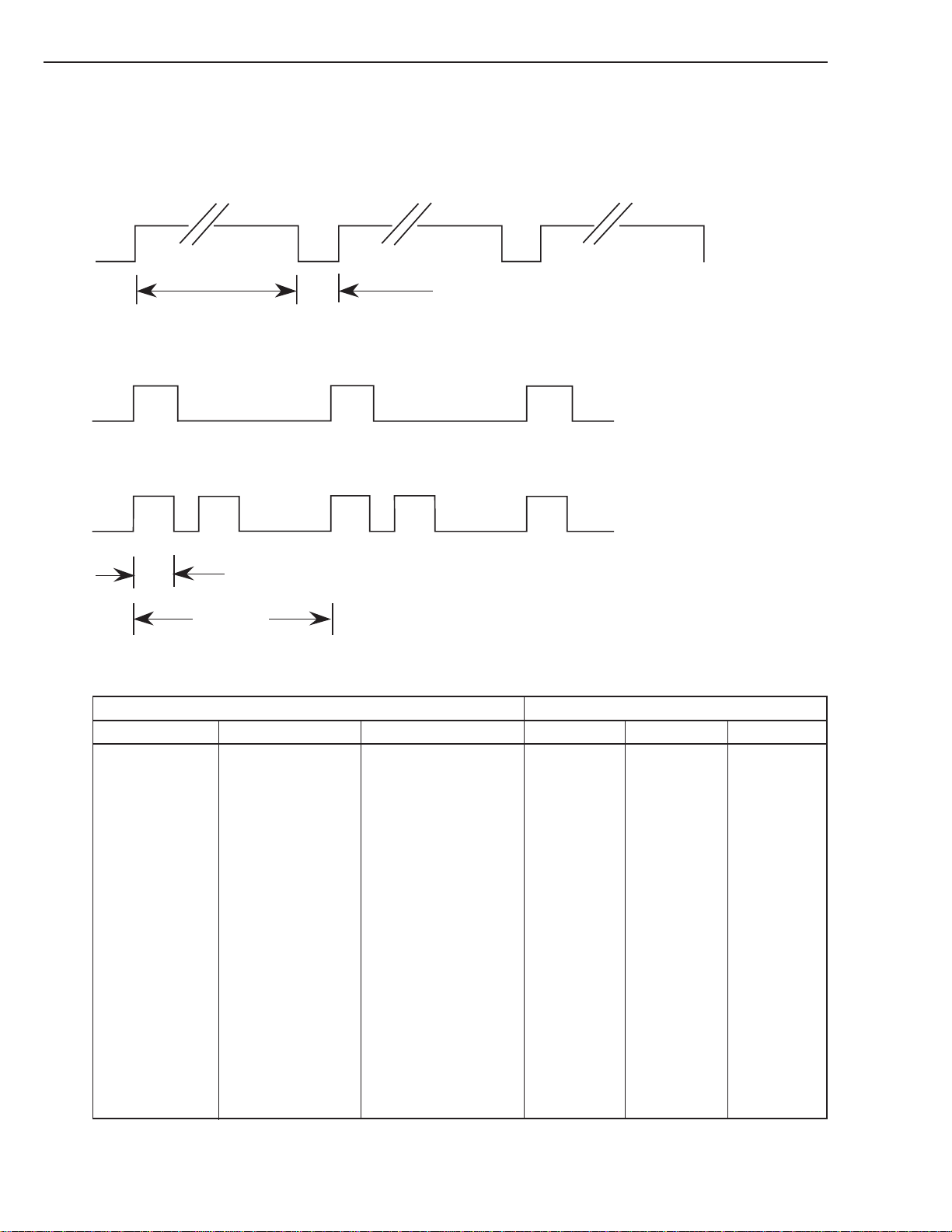
Flashing-2
3.5sec on / 0.5sec off
3.5 sec
0.5 sec
Flash Code LED Indication:
Flash code 1 (one pulse)
Flash code 2 (two pulses)
0.25sec
1.25sec
The following table shows the LED indication for each drive status/condition:
STATE LED
Activity Cartridge Other Busy Tape Status
None None None off off off
SCSI None None on off off
Drive Loading/Unloading None Flashing-1 Flashing-1 off
Drive Loading/Unloading Write Protected Flashing-1 Flashing-1 on
None Loaded Cleaning Tape off on Flashing-1
at EOM
None Loaded None off on off
SCSI Loaded None on on off
SCSI/Drive Loaded None Flashing-1 on off
* Loaded Write Protected * on on
* Loaded Error Rate Warning * Flashing-2
* * Cleaning Request * * Flashing-2
* * Selftest Failure * * Flash code 2
* * Waiting for Reset Flash code 1 * *
* * Waiting for Eject * Flash code 1 *
Illegal FW Tape * Flash code 2 *
Front Panel Test See 4.3.5.1
4 - 2
Table 4-3: LEDs indications for each state
SONY SDT-10000/SDT-11000 DDS Tape Drive
Page 28

4. OPERATION
4. 2 OPERATOR ACTION
4. 2. 1 Powering up the SDT-10000/SDT-11000
After the initial installation of the SDT-10000/SDT-11000 has been verified, power can be applied to the unit. The
+12V and +5V power must be applied simultaneously. The SDT-10000/SDT-11000 will execute a power-up diagnostic
and then comes ready.
Once the tape has been loaded the SDT-10000/SDT-11000 sends a CHECK CONDITION response on receipt of the
next SCSI command from the host. The UNIT ATTENTION key is set in the returned REQUEST SENSE data to
indicate that the tape may have been changed. (Sense Key/ASC/ASCQ = 06/28/00)
4. 2. 2 Inserting Cassettes
The operator inserts a cassette into the slot on the front panel with the arrow on the cassette pointing towards the drive.
As the cassette is inserted, the drive takes it and automatically loads it into the drive mechanism. The SDT-10000/SDT11000 performs a tape load sequence as described in section 4.3.1.
4. 2. 3 Removing Cassettes
The cassette can be removed from the SDT-10000/SDT-11000 either in response to a SCSI UNLOAD command, or by
pressing the Eject button.
The operator uses the Eject button to initiate the unload sequence (see section 4.3.2). The mechanism winds the tape to
Beginning of Media (BOM), unthreads it, and ejects the cassette from the slot.
Note: Operation of the Eject button is disabled if the host has previously sent a SCSI PREVENT ALLOW MEDIA
REMOVAL command with prevent bit set to one. In this case, pressing the Eject button has no effect, and does
not initiate an Unload sequence. The Eject button returns to normal operation following receipt of a PREVENT
ALLOW MEDIA REMOVAL command with prevent bit clear.
4. 2. 4 Write-Protecting Cassettes
Cassettes can be write-protected by sliding the tab on the back of the cassette open. In this state, data can be read from
the tape but not written to it.
When a Write Protected tape is loaded in the drive the Tape and Status LEDs will be lit. The Busy LED will indicate any
activity on the SCSI bus or mechanical motions in the drive itself.
Caution: The Tape Log, which contains a history of usage of the tape, will not be updated when the cassette is write-
protected. It follows that the Tape Log becomes inaccurate if a cassette is used write-protected, and the media
warning cannot be relied on to indicate that the cassette needs to be copied and replaced.
SONY SDT-10000/SDT-11000 DDS Tape Drive
4 - 3
Page 29

4. OPERATION
4. 3 INTERNAL FUNCTION
4. 3. 1 The Load Sequence
During load sequence, the following occurs:
1. The drive mechanism accepts the cassette, threads the tape and rewinds to Beginning-of-Media (BOM). The tape is
then moved to Beginning-of-Tape (BOT) and the Reference area is checked to find the tape format (DDS-4, DDS3, DDS-2, DDS and DDS-DC, blank, audio, and so on). If the format is not DDS-4, DDS-3, DDS-2, DDS and DDSDC, the drive rewinds the tape to BOT and awaits either a WRITE, Partitioning MODE SELECT or an
UNLOAD command.
2. The System area is then accessed and the System log read into the drive.
3. Finally the drive goes online.
In the case of two partition tape the drive detects that the tape has been formatted as a two partition tape when the
Reference Area is read. The drive will then automatically position to the beginning of partition 0 before coming on-line.
Partition 0 is the partition that begins the furthest from BOM.
4. 3. 2 The Unload Sequence
The drive will always write any buffered data out to tape followed by an EOD prior to initiating the Unload sequence.
During this sequence the tape is rewound to BOT and, if the tape is write-enabled, the copy of the tape log held in RAM
is written back to tape. The tape is then rewound to BOM and the tape unthreaded from the mechanism. At this stage the
tape is either retained in the drive or ejected, depending on media removal is enabled by the PREVENT ALLOW
MEDIA REMOVAL command.
In the case of two partition tape the drive detects that the tape has been formatted as a two partition tape when the
Reference Area is read during the load sequence. When the Unload operation begins the drive will then automatically
update the Tape Log for each partition before unloading the tape.
4. 3. 3 Power-Fail Handling
If there is a power-fail, the SDT-10000/SDT-11000 performs the following actions, and reverts to its default configuration:
1. The drive remains positioned at the point where the power-fail or SCSI Reset occurred.
2. It executes the Power-Up sequence of self-tests. (When power is restored.)
3. If a tape is in the drive, the SDT-10000/SDT-11000 starts a load sequence.
The drive rewinds the tape to BOT and remains on-line.
4. The drive returns CHECK CONDITION status for the first command after the power-fail or Reset. The next
command from the initiator should be a REQUEST SENSE. The drive will return sense data including a sense key
that will indicate that the drive has been reset. (Sense Key / ASC / ASCQ = 06/29/00)
4. 3. 4 Diagnostic and Normal Status Displays
This chapter describes LED displays while the SDT-10000/SDT-11000 is starting up. When power is turned on, the
SDT-10000/SDT-11000 will go through its diagnostics to reach normal status. When a failure is detected during diagnostics, the LEDs show that the SDT-10000/SDT-11000 is out of order and needs to be repaired.
4. 3. 4. 1 Diagnostic Status Display
The SDT-10000/SDT-11000 starts with its Diagnostic function. This is made up of the Front Panel Test and the Kernel
Test.
4 - 4
SONY SDT-10000/SDT-11000 DDS Tape Drive
Page 30

4. OPERATION
4. 3. 4. 1. 1 Front Panel Test
LED display sequence:
Busy
0.25 sec
0.25 sec
0.25 sec
0.25 sec
0.25 sec
0.25 sec
0.25 sec
0.25 sec
0.25 sec
0.25 sec
0.25 sec
0.25 sec
0.25 sec
Note: This function is for checking BUSY, STATUS and TAPE LEDs and the related circuits. No errors can be gener-
ated as this test is only for operator verification of indicator operation.
on
-
on
-
on
-
-
on
-
-
on
-
-
Tape
on
-
on
-
-
on
-
-
on
-
-
on
-
Status
on
-
on
-
-
-
on
-
-
on
-
-
on
Front Panel
Test
repeat until end of
Power On Diagnostic
4. 3. 4. 1. 2 Kernel Test
After the Front Panel Test, the SDT-10000/SDT-11000 checks its internal units.
Note: If a failure is detected, the SDT-10000/SDT-11000 displays the Failed Unit. Refer to section 4. 3. 4.
When a Diagnostic error occurs, the SDT-10000/SDT-11000 must be powered off. The SDT-10000/SDT-11000 will
not work and should be checked or repaired immediately.
Note: The purpose of the diagnostic firmware is to test the SDT-10000/SDT-11000 electronics for functionality. If the
diagnostic request comes from the host through SCSI, then the results are reported through SCSI.
If the electronics are not functioning, the diagnostic firmware tries to isolate the non-functional area to a specific Failed
Unit. Given a failure, the firmware decides on an hierarchical basis which Unit to designate as the Most Suspect Failed
Unit (MSFU). The confidence in this decision is intended to be 95%. The MSFU is identified and displayed on the front
panel as shown above section 4. 3. 4. For the details of Diagnostics, see section 7.
SONY SDT-10000/SDT-11000 DDS Tape Drive
4 - 5
Page 31

4. OPERATION
4. 3. 4. 2 Normal Status Display
After the Diagnostic Display, when no failures are detected, the SDT-10000/SDT-11000 is in the Normal Status. The
LEDs show various Normal Status (No Error) indications as shown in the table below:
Activity Cartridge Other Busy Tape Status
None None None off off off
SCSI None None on off off
Drive Loading/Unloading None Flashing-1 Flashing-1 off
Drive Loading/Unloading Write Protected Flashing-1 Flashing-1 on
None Loaded Cleaning Tape off on Flashing-1
None Loaded None off on off
SCSI Loaded None on on off
SCSI/Drive Loaded None Flashing-1 on off
STATE LED
at EOM
* Loaded Write Protected * on on
Table 4-4: Normal LED indications
4. 3. 4. 3 Media Warning
When a Media Warning threshold is exceeded the drive will indicate that the tape is bad by flashing the Tape LED. The
indicator will be on for 3.5 seconds, off for 0.5 seconds. The Busy and Status LEDs will operate normally.
If this occurs, the data on the cassette should be copied onto a new one and the old cassette discarded.
This status is cleared by unloading the cassette.
The Media Warning is displayed if any of the following conditions are met:
- More than 1 RAW rewrite per 4 groups written
- More than 1 read retry per 512 groups read
- More than 1 ECC C3 error correction per 128 groups read
Note: Media warning is calculated as an average value of 1024 groups of data (either Read or Write) 1024 Groups of
data is approximately 390 MB.
4 - 6
SONY SDT-10000/SDT-11000 DDS Tape Drive
Page 32

4. OPERATION
4. 4 TAPE FORMAT
The SDT-10000/SDT-11000 is an implementation of the Digital Data Storage (DDS) format, a standard developed by
Sony and Hewlett-Packard for 4mm data storage drives. It incorporates the error correction techniques used in DAT
audio drives with additional techniques specifically designed to provide the optimum level of data integrity. These extra
methods of error detection and correction are:
- C3 ECC, third level Error Correction Code, providing correction across frames within groups
- Read-After-Write, where data is verified immediately after it is written and re-written if there is any error.
- N-Group Writing, where every group is repeated a set number of times. (DDS, DDS-DC, DDS-2 only)
- Randomizer, to reduce inter-symbol interference.
- Track checksums, to detect and locate helical errors, thereby improving the performance of C3 ECC.
4. 4. 1 Tape Partitions
Tapes can be formatted as a single data space or as two partitions. With two partitions, each has the same structure and
can be written independently. So, for example, the partition further from BOM (Partition 0) can contain data files, and
the partition closer to BOM (Partition 1) could contain a directory of these files, written later.
With the exception of the Device area on the tape, each partition of a 2-partition tape is identical to a single data space
tape in structure. This means each partition has its own Tape Log area; this is necessary because the patterns of usage
may be very different for each partition. Similarly, each has its own Vendor Group, because the partitions might be
written by different drives.
4. 4. 1. 1 Formatting Partitions
The SCSI MODE SELECT command is used to create partitions on a tape. The command can perform the following
operations:
- Set up two partitions on a blank tape.
- Convert a single data space tape to a 2-partition tape.
- Convert a 2-partition tape to a single data space tape.
- Change the size of both partitions on a 2-partition tape.
- Resize the partitions of a 2-partition.
Note: Formatting is not needed for single partition operation.
The MODE SELECT, Medium Partitions Parameters Page (11h) is used to Format the tape.
MODE SELECT, Device Configuration Page (10h) is used to change from one partition to another, see the MODE
SELECT Command description in the SCSI command section of this manual. The LOCATE Command also has the
capability to select a partition prior to positioning.
Any data on the tape before the format pass becomes inaccessible, even if the format pass is intended only to change the
size of the two partitions. The Tape Logs are also destroyed and new logs created.
If you do not format a new tape, it will be organized as a single data space tape. After data has been written to it, whether
it was first initialized or not, a format pass is necessary to alter its characteristics and hence how it is handled by the tape
drive system.
Note: The format operation can be very time consuming depending on the requested size of the first partition on the
tape. The amount of time required can be approximated by use of the following formula:
- Number of Megabytes in Partition 1 x 1.4 = number of seconds required (DDS, DDS-DC, DDS-2)
- Number of Megabytes in Partition 1 x 0.5 = number of seconds required (DDS-3, 4)
- Add about 60 additional seconds for processing overhead
SONY SDT-10000/SDT-11000 DDS Tape Drive
4 - 7
Page 33

4. OPERATION
4. 5 MAINTENANCE, TROUBLESHOOTING AND SERVICE
4. 5. 1 Head Cleaning
The SDT-10000/SDT-11000 has a built-in head cleaner designed to last for the life of the drive. In addition, a cleaning
tape should be used periodically to clean the entire tape path.
The drive will automatically request that the user perform a cleaning operation (described below). The need for a
cleaning is determined by the length of time that the drum has been rotating since the last cleaning was performed. The
drive will request a cleaning cycle after every 24 hours of drum rotation.
The Cleaning Request is indicated by the Status LED flashing:
- on for 3.5 seconds
- off for 0.5 seconds
4. 5. 2 Troubleshooting Guide
Problems encountered while operating the Sony SDT-10000/SDT-11000 tape drive fall into two categories: Operational problems and Read/Write problems.
Operational problems include any conditions that prevent the tape drive from operating. Operational problems usually
are discovered the first time the drive is installed on a system or when the system configuration is changed or physically
moved.
Read/Write problems include conditions that effect the transfer of data to and from the tape drive. Commands such as
REWIND, REQUEST SENSE and UNLOAD perform normally but data transfers fail.
The following sections describe the recommended procedures for solving operational and read/write problems.
4. 5. 2. 1 Operational Problems
1. The tape drive will not accept a tape cartridge.
Withdraw the tape cassette and turn the power to drive off, wait 5 seconds, then back on. Observe the drive for a
normal power up sequence (See Section 4.3.4 ).
If the LEDs do not light, check the power supply and power cable connection. If the drive completes the power on
sequence normally but still won’t accept the tape cassette, the drive may be defective.
A tape may already be in the drive. Tape LED is on. Press EJECT to remove the first tape.
The power has been removed from the drive with a tape loaded. When the power is restored to the drive, it will
detect the tape and rewind the tape to BOT. Press EJECT to remove the cassette.
2. A tape is in the drive and will not eject.
If the SCSI command PREVENT ALLOW MEDIA REMOVAL (with Prevent bit set to one) has been sent to the
drive, the cartridge will be retained in the drive even after an UNLOAD command. The EJECT button is also
disabled. Send an PREVENT ALLOW MEDIA REMOVAL (with prevent bit clear) command, issue a SCSI bus
reset, or power the drive off and back on to override this condition.
4 - 8
SONY SDT-10000/SDT-11000 DDS Tape Drive
Page 34
4. OPERATION
If Tape is still in the drive after following the above procedure.
The drive has a serious problem and should be returned to Sony for repair with the tape in place.
Note: If it is absolutely mandatory that the tape cassette be removed prior to returning the drive for repair the following
Emergency Cassette Removal procedure should be followed.
Caution: This procedure should only be attempted by a mechanically qualified person and will probably result in the
tape being unusable. Do not proceed if further damage to the tape drive would be done.
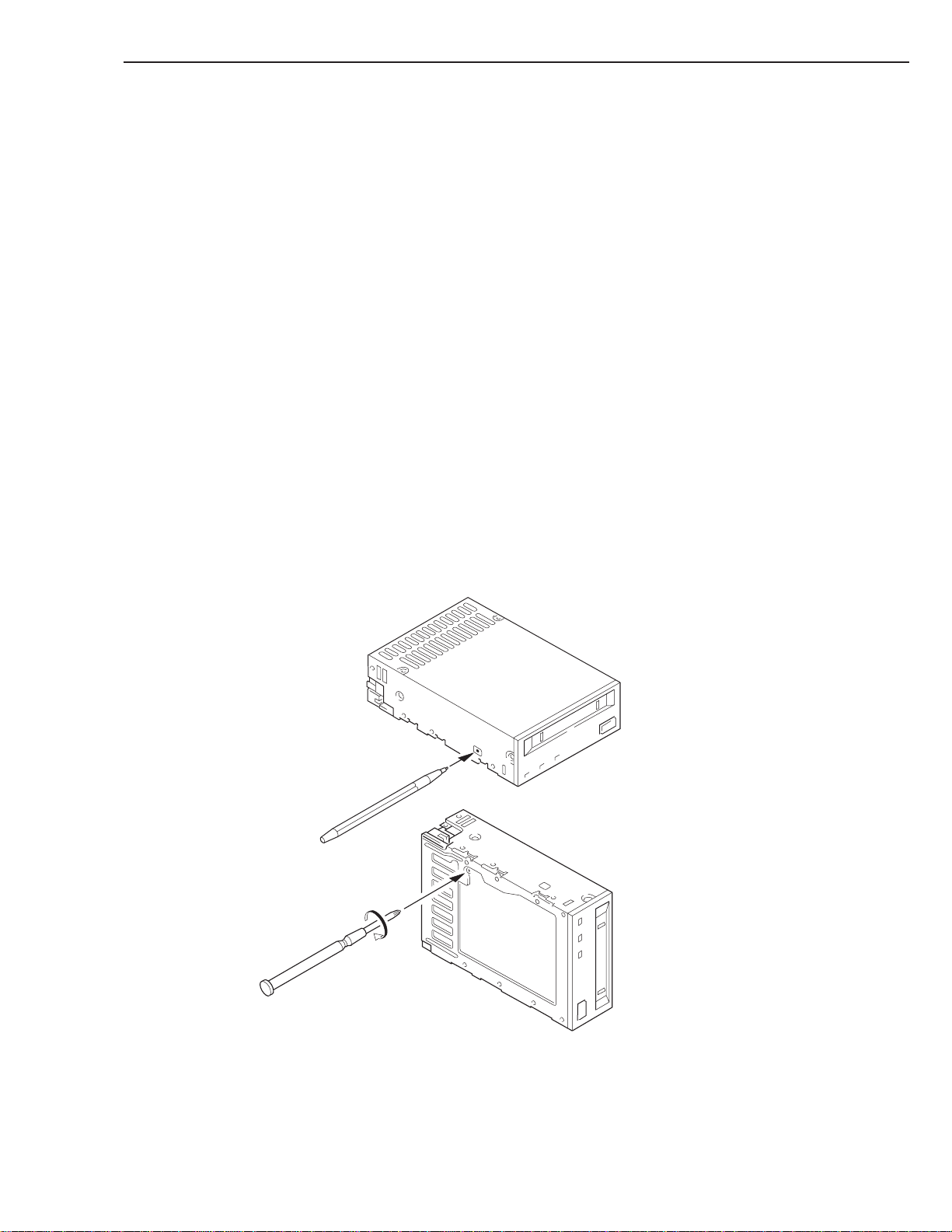
Emergency Cassette Removal Procedure
1. Remove the drive from the chassis or enclosure to allow access to the bottom and left side of the drive.
2. Remove the drive’s top cover.
3. Locate the small opening in the bottom of the drive and insert the tip of a small screwdriver so that the Loading/
Threading motor shaft can be rotated.
4. Rotate the motor shaft clockwise to bring the threading mechanism back to the initial position.
5. Before continuing the manual eject procedure, tape slack must be removed in order to prevent tape damage. Repeat-
edly press the ratchet mechanism located on the left side of the drive to tighten the tape.
6. After the tape slack has been removed, continue to turn the motor shaft clockwise until the tape is lifted out of the
drive mechanism and is ejected.
7. Return the drive to Sony for repair.
The following figure shows the drive access points for the Emergency Cassette Removal Procedure:
Figure 4-1: Emergency Tape Removal Procedure
SONY SDT-10000/SDT-11000 DDS Tape Drive
4 - 9
Page 35

4. OPERATION
3. The drive powers up properly and loads and unloads tapes but will not respond to any SCSI commands.
A. If SCSI bus reset does not cause the drive to reset (same as power-on self test):
- Check the SCSI cable connectors
- Check SCSI cable pin one is aligned with the SCSI connector pin one
- Check for a broken cable or defective connector
- Try another known good SCSI device in the same location.
B. If SCSI bus reset causes the drive to reset then the problem is with the SCSI bus addressing or termination.
- Check that the SCSI bus ID jumper is set for the proper address
(See Section 3.1.1.)
- Check SCSI bus termination
The two SCSI devices at the ends of the bus should be terminated
No other units should have terminators installed
Note: The strength of the SCSI bus signals can be affected if too many terminators are installed (Signal drivers can be
damaged as well)
4. 5. 2. 2 Read/Write Problems
To prevent read/write errors, follow the cleaning recommendation in section 4.5.
If a read/write error occurs, a combination of the following steps should correct the problem.
- Remove the tape.
- Clean the drive with the DDS cleaning cartridge.
- Load a new tape in the drive.
- Retry the operation.
Note: If these steps do not correct the problem the drive may be defective and should be returned to Sony for service.
4. 5. 3 Clearance for Service
All servicing is performed only after removal of the SDT-10000/SDT-11000 from its mounting.
It is recommended that in mounting the drive into a chassis provisions should be made to allow easy access to the
mounting screws (see Figure 2-2).
4. 5. 4 Packaging for Return to Sony
The drive should be returned in its original packaging.
Sony will not take responsibility for shipping damage caused to an improperly packaged drive.
4 - 10
SONY SDT-10000/SDT-11000 DDS Tape Drive
Page 36

4. OPERATION
4. 6 DATA COMPRESSION
The tape capacity is increased by compressing data prior to writing it to the tape. Data compression is a well established
technology for reducing the number of bits used to represent data in order to improve data transfer rate as well as reduce
the amount of storage space consumed by the data.
The SDT-10000/SDT-11000 uses the AK 8320 Data Compression IC from ASAHI KASEI MICROSYSTEMS. This
chip provides a powerful data compression algorithm in a very small package. The data compression used by the chip is
the DCLZ algorithm. DCLZ has been standardized (or is in the process of standardization) with the ANSI, ECMA and
ISO standards organizations. The DDS Manufacturers Group (made up of representatives from active DDS Format
Licensees) has agreed upon the DCLZ algorithm as the standard data compression algorithm for data interchange between DDS format drives.
The DC control page allows the host computer to enable data compression and also configure the way in which the drive
responds to compressed/uncompressed data boundaries on the tape.
Note: The DDS format allows both compressed and uncompressed data to reside on the same tape.
SDT-10000/SDT-11000 has a Dip switch to disable the Data Compression.
After power-on reset with this jumper set, data compression is disabled. However, a MODE SELECT command can
override the setting of this jumper.
After power-on reset without this Dip switch set, both data compression and data decompression are enabled. (See
3.1.5)
The more random the data is, the less compression is possible. This is due to the fact that data compression operates on
the principle of reducing the redundancy in the data string and random data has very little redundancy.
Data compression is a very powerful and reliable method increasing data capacity and transfer rate without compromising data reliability.
SONY SDT-10000/SDT-11000 DDS Tape Drive
4 - 11
Page 37

5. SCSI INTERFACE
5
5
5
5
5
5
5
5. 1 INTRODUCTION ........................................................................................................ 5-1
5. 1. 1 Overview of the SCSI Interface .................................................................... 5-1
5. 1. 2 Supported Messages .................................................................................. 5-1
5. 1. 3 Supported and Unsupported Commands ................................................. 5-2
5. 2 SCSI BUS OPERATION ............................................................................................ 5-3
5. 2. 1 Typical SCSI Operation............................................................................... 5-3
5. 2. 2 Disconnect ................................................................................................... 5-3
5. 3 MESSAGE SPECIFICATION .................................................................................... 5-5
5. 3. 1 COMMAND COMPLETE (00h).................................................................... 5-5
5. 3. 2 EXTENDED MESSAGE (01h) ..................................................................... 5-5
5. 3. 2. 1 SYNCHRONOUS DATA TRANSFER REQUEST....................... 5-5
5. 3. 2. 2 WIDE DATA TRANSFER REQUEST.......................................... 5-7
5. 3. 3 SAVE DATA POINTER (02h) ..................................................................... 5-9
5. 3 .4 RESTORE POINTERS (03h) ........................................................................ 5-9
5. 3. 5 DISCONNECT (04h) ..................................................................................... 5-9
5. 3. 6 INITIATOR DETECTED ERROR (05h)....................................................... 5-9
5. 3. 7 ABORT (06h) .............................................................................................. 5-10
5. 3. 8 MESSAGE REJECT (07h)......................................................................... 5-10
5. 3. 9 NO OPERATION (08h) .............................................................................. 5-10
5. 3. 10 MESSAGE PARITY ERROR (09h)......................................................... 5-10
5. 3. 11 BUS DEVICE RESET (0Ch) ................................................................... 5-10
5. 3. 12 IGNORE WIDE RESIDUE (23h) ............................................................... 5-11
5. 4 STATUS SPECIFICATION...................................................................................... 5-12
234
234
234
234
234
234
234
Page 38

5. SCSI INTERFACE
5. SCSI INTERFACE
5. 1 INTRODUCTION
The SDT-10000/SDT-11000 uses the SCSI interface to connect to the host system.
The Small Computer System Interface (SCSI) is an industry standard interface, approved by the American National
Standards Institute (ANSI). It is recommended that this document be used along with the ANSI standard document. The
ANSI specification defines the interface in general while this document describes the specific implementation for this
unit.
The SCSI documents, listed in detail in section 1.2, offer the information required to integrate this unit with SCSIcompatible computer systems.
This section is divided into four sub-sections:
• Introduction
• SCSI Bus Operation
• SCSI Messages
• SCSI Status
Note: The details of each SCSI Command are covered in section 6.
The Introduction provides general, high-level information. For the hardware description and the installation requirements, see section 2.
The SCSI protocol supported by the unit are covered in the Bus Operation, Message, and Status sections.
5. 1. 1 Overview of the SCSI Interface
The SCSI implementation provides the unit with a standard set of features and functions. These include:
• Asynchronous and Synchronous communication modes
• Single-ended / Differential Configurations
• Full implementation of Mandatory commands
• Implementation of most sequential non-Mandatory commands
5. 1. 2 Supported Messages
The following messages are supported: (alphabetic order)
* Abort
* Bus Device Reset
* Command Complete
* Disconnect
* Extended Message - Synchronous Data Transfer Request
* Identify (w/ & w/o disconnect)
* Initiator Detected Error
* Message Parity Error
* Message Reject
* No Operation
* Restore Pointers
* Save Data Pointer
For implementation details on these messages, see the Message Specification section.
SONY SDT-10000/SDT-11000 DDS Tape Drive
5 - 1
Page 39

5. SCSI INTERFACE
5. 1. 3 Supported and Unsupported Commands
The following commands are supported. They include all Mandatory and Extended commands, most Optional commands.
Command Name Code
ERASE 19h
INQUIRY 12h
LOAD/UNLOAD 1Bh
LOCATE 2Bh
LOG SELECT 4Ch
LOG SENSE 4Dh
MODE SELECT(6) 15h
MODE SENSE(6) 1Ah
PREVENT ALLOW MEDIUM REMOVAL 1Eh
READ 08h
READ BLOCK LIMITS 05h
READ BUFFER 3Ch
READ POSITION 34h
RECEIVE DIAGNOSTIC RESULTS 1Ch
RELEASE UNIT 17h
REPORT DENSITY SUPPORT 44h
REPORT LUNS A0h
REQUEST BLOCK ADDRESS 02h
REQUEST SENSE 03h
RESERVE UNIT 16h
REWIND 01h
SEEK BLOCK 0Ch
SEND DIAGNOSTIC 1Dh
SPACE 11h
TEST UNIT READY 00h
VERIFY 13h
WRITE 0Ah
WRITE BUFFER 3Bh
WRITE FILEMARKS 10h
Operation
5 - 2
Table 5-1: Supported SCSI Commands
SONY SDT-10000/SDT-11000 DDS Tape Drive
Page 40

5. SCSI INTERFACE
For implementation details on these commands, see the Command section.
The following Optional commands are NOT supported.
- CHANGE DEFINITION
- COMPARE
- COPY AND VERIFY
- 10 byte MODE SENSE & MODE SELECT
- READ REVERSE
- TRACK SELECT (SCSI-1 optional command, not applicable to the SDT-10000/SDT-11000)
5. 2 SCSI BUS OPERATION
5. 2. 1 Typical SCSI Operation
This example describes the typical SCSI bus sequence between the host and the drive.
1. After waiting for the bus clear time the Host arbitrates for the SCSI bus. It does this by asserting BSY and the data
line corresponding to its bus ID. If any other devices wish to compete for the bus, they also assert BSY and the
appropriate data line. Each arbitrating device then inspects the data bus. The device with the highest ID wins the
bus. All the other devices must release BSY and their data lines.
2. The Host attempts to select the target by asserting SEL and releasing BSY. The Host maintains its ID and asserts the
target’s ID on the data bus. Each target then checks the data lines. If the target’s ID matches that on the data bus, it
accepts selection by asserting BSY. Once the Host has detected BSY being asserted, it asserts ATN to indicate that
it wants the target to go to the MESSAGE OUT phase. The Host releases SEL.
3. The target now has control of the SCSI bus and it is the target which switches between phases. The target responds
to the ATTENTION condition and initiates the MESSAGE OUT phase. The Host sends an IDENTIFY message
which tells the target which logical unit the Host wishes to talk to. The fact that the target responds to the ATN
indicates to the Host that the target can accommodate more than just a COMMAND COMPLETE message.
4. The target initiates the COMMAND phase and transfers the Command Descriptor Block from the Host. In the
COMMAND phase, the target decodes the command and either executes the command (TEST UNIT READY) or
sets itself up for a data transfer to the Host (READ, WRITE, INQUIRY etc.). The target then either switches to the
STATUS phase, if the command is complete, or if it is ready to transfer data, the DATA phase.
5. The data transfer length is set by the Host in the Command Descriptor Block. The target will remain in the DATA
phase until all the data is transferred.
6. The target then initiates a STATUS phase and transfers one byte to the Host to indicate whether the target has
successfully completed the command. If the target has detected an error, the next command that the Host is expected to send is REQUEST SENSE. This allows the target to return further status information to the Host.
7. The target completes the SCSI sequence by going to the MESSAGE IN phase and transferring a COMMAND
COMPLETE message to the Host. The target then releases BSY allowing the bus to go to the BUS FREE state.
5. 2. 2 Disconnect
In order to improve bus usage and performance, the unit is capable of temporarily disconnecting from the bus, consequently allowing other initiator-target communications to take place. To do so, however, the Host needs to support
Disconnect/Reselect. The mechanism for performing the Disconnect/Reselect procedure is implemented as follows:
1. The Host arbitrates for the SCSI bus and upon winning the bus it proceeds to select target device. Prior to releasing
SEL and completing the selection phase, the Host asserts the ATN line. The Host then releases SEL and BSY to
allow the target to assume control of the SCSI bus. By asserting ATN, the host indicates that the target should go to
a MESSAGE OUT phase.
SONY SDT-10000/SDT-11000 DDS Tape Drive
5 - 3
Page 41

5. SCSI INTERFACE
2. At this point, the target responds to the Host ATTENTION condition by initiating a MESSAGE OUT phase and
receiving a message from the Host which tells it whether or not the Host allows Disconnects for the desired logical
unit on the target.
3. If the Host does not send an Identify message, the target assumes that Disconnects are not permitted.
4. The I/O activity from this point is controlled entirely by the target. The target initiates the COMMAND phase and
reads in the Command Descriptor Block (CDB) from the Host. If the Host has sent an Identify message with the
Disconnect permission bit set, then the target will immediately disconnect from the bus after the entire CDB has
been received.
5. The Disconnect process occurs when the target initiates a MESSAGE IN phase and sends a DISCONNECT message back to the Host. This message may be preceded by a SAVE DATA POINTERS message byte if the Disconnect is performed in the middle of the DATA phase. Following the MESSAGE IN phase, the target frees the bus by
releasing the BSY.
6. The host now waits for the target to perform Reselection. When ready, the target reselects the Host and sends an
Identify message via a MESSAGE IN phase, indicating the specific logical unit with which the subsequent communications are to take place. Usually, the target will proceed from the MESSAGE IN phase to either a DATA or a
STATUS phase. If the Host had been previously told to SAVE DATA POINTERS, then the target’s Identify message implies that the Host restores its data pointers upon reselection; in other words, it is not necessary for the target
to send a specific RESTORE DATA POINTERS to the Host in such context.
7. When doing a large data transfer, the target may choose to divide the entire transfer into several smaller transfers.
This allows the target to free the SCSI bus whenever it needs to perform its own system tasks not immediately
related to the actual data transfer over the SCSI bus. The target will not lock the bus into the DATA phase if it is not
presently ready to efficiently execute the transfer.
After the data transfer is completed, the target enters a STATUS phase and sends a single status byte to the Host. It
then proceeds to a MESSAGE IN phase, during which the target sends a COMMAND COMPLETE message.
Finally, the target frees the bus and the current command is considered completed.
8. The Host may change Disconnect permission at any time after the SELECTION phase by asserting ATN and
sending an Identify message via a MESSAGE OUT phase. If the Host, however, performs this action during a
DATA phase, it is possible that the target will not notice the change in Disconnect permission status until past the
end of the current bus phase.
5 - 4
SONY SDT-10000/SDT-11000 DDS Tape Drive
Page 42

5. SCSI INTERFACE
5. 3 MESSAGE SPECIFICATION
This section includes all SCSI messages. Both supported and non-supported messages are listed. Elements of this
section come from section 5, Logical Characteristics, of the SCSI standard.
The message system allows communication between an initiator and a target for the purpose of physical path management. The table below lists the Messages supported by the SDT-10000/SDT-11000.
Code Description Direction
In Out
00 COMMAND COMPLETE *
01 EXTENDED MESSAGE (Note 1) * *
02 SAVE DATA POINTER *
03 RESTORE POINTERS *
04 DISCONNECT *
05 INITIATOR DETECTED ERROR *
06 ABORT *
07 MESSAGE REJECT * *
08 NO OPERATION *
09 MESSAGE PARITY ERROR *
0C BUS DEVICE RESET *
23 IGNORE WIDE RESIDUE *
80- FF IDENTIFY * *
Table 5-2: Message Descriptions
Note: The SDT-10000/SDT-11000 supports the Synchronous Data Transfer Request Extended Message.
5. 3. 1 COMMAND COMPLETE (00h)
This message is sent from a target to an initiator to indicate that the execution of a command has completed and valid
status has been sent to the initiator. After successfully sending this message, the target goes to the BUS FREE phase by
releasing BSY.
When received as a target, it will be handled as an illegal message, the unit will return MESSAGE REJECT and will
continue.
5. 3. 2 EXTENDED MESSAGE (01h)
5. 3. 2. 1 SYNCHRONOUS DATA TRANSFER REQUEST
This is sent by either the initiator or the target as the first byte of a multiple-byte message. When acting as an initiator,
the unit will not send any Extended Messages. No Vendor Unique codes are implemented and only the Synchronous
Data Transfer Request code is supported. Any other message code is handled as an illegal message; the unit will return
MESSAGE REJECT and will continue. A Synchronous Data Transfer Request message has the following format:
Byte Value Description
0 01h Extended message
1 03h Extended message length
2 01h SYNCHRONOUS DATA TRANSFER REQUEST code
3 m Transfer period (m times 4 nanoseconds)
4 x REQ/ACK offset
Table 5-3: Synchronous Data Transfer Request
SONY SDT-10000/SDT-11000 DDS Tape Drive
5 - 5
Page 43
5. SCSI INTERFACE
A SYNCHRONOUS DATA TRANSFER REQUEST (SDTR) message exchange shall be initiated by an SCSI device
whenever a previously-arranged data transfer agreement may have become invalid. The agreement becomes invalid
after any condition which may leave the data transfer agreement in an indeterminate state such as:
(1) after a hard reset condition
(2) after a BUS DEVICE RESET message and
(3) after a power cycle
In addition, an SCSI device may initiate an SDTR message exchange whenever it is appropriate to negotiate a new data
transfer agreement (either synchronous or asynchronous). SCSI devices that are capable of synchronous data transfers
shall not respond to an SDTR message with a MESSAGE REJECT message.
The SDTR message exchange establishes the permissible transfer periods and the REQ/ACK offsets for all logical units
and target routines on the two devices. This agreement only applies to data phases. The transfer period factor times four
is the value of the transfer period.
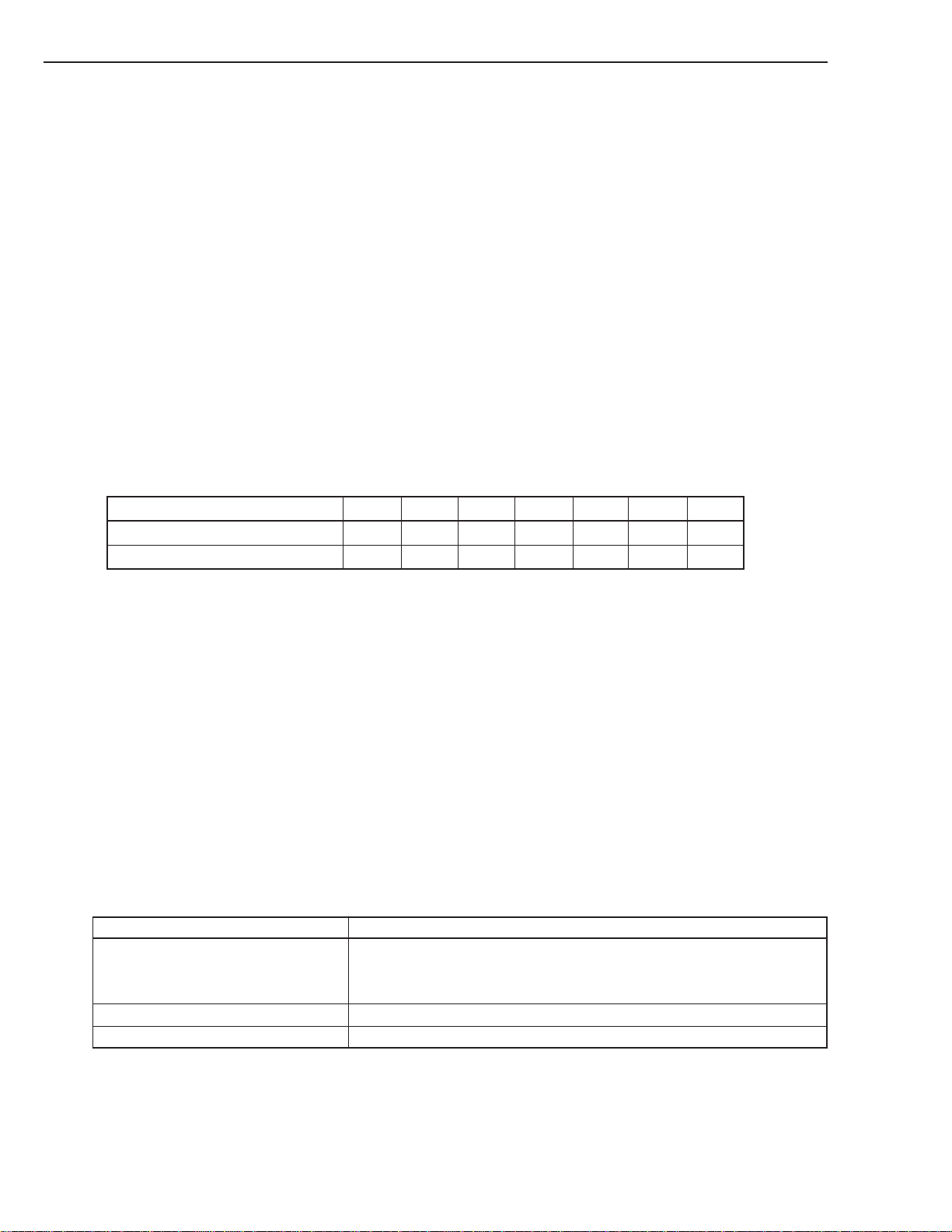
Transfer period is the minimum time allowed between leading edges of successive REQ pulses and of successive ACK
pulses. The SDT-10000/SDT-11000 supports the following transfer periods:
Transfer Period (hex) 0C 19 1F 26 2C 32 38
Transfer Rate (MB/sec) - narrow 20.0 10.0 8.0 6.67 5.71 5.00 4.44
Transfer Rate (MB/sec) - wide 40.0 20.0 16.0 13.34 11.42 10.00 8.88
Table 5-4: Synchronous Data Transfer Rates
REQ/ACK offset: is the maximum number of REQ pulses allowed to be outstanding before the leading edge of its
corresponding ACK pulse is received at the target. A REQ/ACK offset value of ZERO shall indicate asynchronous data
transfer mode. The SDT-10000/SDT-11000 supports synchronous data transfer REQ/ACK offset values from 1 to 15.
The originating device (the device that sends the first of the pair of SDTR messages) sets its values according to the rules
above to permit it to receive data successfully. If the responding device can also receive data successfully with these
values (or smaller transfer periods or larger REQ/ACK offsets or both), it returns the same values in its SDTR message.
If it requires a larger transfer period, a smaller REQ/ACK offset, or both in order to receive data successfully, it substitutes values in its SDTR message as required, returning unchanged any value not required to be changed. Each device
when transmitting data shall respect the limits set by the other’s SDTR message, but it is permitted to transfer data with
larger transfer periods, smaller REQ/ACK offsets, or both than specified in the other’s SDTR message. The successful
completion of an exchange of SDTR messages implies an agreement as follows:
Responding Device SDTR response Implied Agreement
(1) Non-ZERO REQ/ACK offset Each device transmits data with a transfer period equal to or greater than
and a REQ/ACK offset equal to or less than the values received in the other
device’s SDTR message.
(2) REQ/ACK offset equal to ZERO Asynchronous transfer
(3) MESSAGE REJECT message Asynchronous transfer
5 - 6
If the initiator recognizes that negotiation is required, it asserts the ATN signal and sends a SDTR message to begin the
negotiating process. After successfully completing the MESSAGE OUT phase, the target shall respond with the proper
SDTR message. If an abnormal condition prevents the target from returning an appropriate response, both devices shall
go to asynchronous data transfer mode for data transfers between the two devices.
SONY SDT-10000/SDT-11000 DDS Tape Drive
Page 44

5. SCSI INTERFACE
Following target response (1) above, the implied agreement for synchronous operation shall be considered to be negated
by both the initiator and the target if the initiator asserts the ATN signal and the first message out is either MESSAGE
PARITY ERROR or MESSAGE REJECT. In this case, both devices shall go to asynchronous data transfer mode for
data transfers between the tow devices. For the MESSAGE PARITY ERROR case, the implied agreement shall be
reinstated if a re-transmittal of the second of the pair of messages is successfully accomplished. After two retry attempts, if the target receives a MESSAGE PARITY ERROR message, it shall terminate the retry activity. This may be
done either by changing to any other information transfer phase and transferring at least one byte of information or by
going to the BUS FREE phase. The initiator shall accept such action as aborting the negotiation, and both devices shall
go to asynchronous data transfer mode for data transfer between the two devices.
If the target recognizes that negotiation is required, it sends an SDTR message to the initiator. Prior to releasing the ACK
signal on the last byte of the SDTR message from the target, the initiator shall assert the ATN signal and respond with its
SDTR message or with a MESSAGE REJECT message. If an abnormal condition prevents the initiator from returning
an appropriate response, both devices shall go to asynchronous data transfer mode for data transfers between the two
devices.
Following an initiator’s responding SDTR message, an implied agreement for synchronous operation shall not be considered to exist until the target leaves the MESSAGE OUT phase, indicating that the target has accepted the negotiation.
After two retry attempts, if the target has not received the initiator’s responding SDTR message, it shall go to the BUS
FREE phase without any further information transfer attempt. This indicates that a catastrophic error condition has
occurred. Both devices shall go to asynchronous data transfer mode for data transfer between the two devices.
If, following an initiator’s responding SDTR message, the target shifts to MESSAGE IN phase and the first message in
is MESSAGE REJECT, the implied agreement shall be considered to be negated and both devices shall go to asynchronous data transfer mode for data transfers between the two devices.
The implied synchronous agreement shall remain in effect until a BUS DEVICE RESET message is received, until a
hard reset condition occurs, or until one of the two SCSI devices elects to modify the agreement. The default data
transfer mode is asynchronous data transfer mode. The default data transfer mode is entered at power on, after a BUS
DEVICE RESET message, or after a hard reset condition.
5. 3. 2. 2. WIDE DATA TRANSFER REQUEST
Byte Value Description
0 01h Extended message
1 03h Extended message length
2 01h WIDE DATA TRANSFER REQUEST code
3 m Transfer Width exponent
A WIDE DATA TRANSFER REQUEST (WDTR) message exchange shall be initiated by an SCSI device whenever a
previously-arranged transfer width agreement may have become invalid. The agreement becomes invalid after any
condition which may leave the data transfer agreement in an indeterminate state such as:
(1) after a hard reset condition
(2) after a BUS DEVICE RESET message and
(3) after a power cycle
SONY SDT-10000/SDT-11000 DDS Tape Drive
5 - 7
Page 45

5. SCSI INTERFACE
In addition, an SCSI device may initiate a WDTR message exchange whenever it is appropriate to negotiate a new
transfer width agreement. SCSI devices that are capable of wide data transfers (greater than eight bits) shall not respond
to a WDTR with a MESSAGE REJECT message.
The WDTR message exchange establishes an agreement between two SCSI devices on the width of the data path to be
used for DATA phase transfers between the two devices. This agreement applies to DATA IN and DATA IN and DATA
OUT phase only. All other information transfer phase shall use an eight-bit data path.
If an SCSI device implements both wide data transfer option and synchronous data transfer option, then it shall negotiate
the wide data transfer agreement prior to negotiating the synchronous data transfer agreement. If a synchronous data
transfer agreement is in effect, then an SCSI device that accepts a WDTR message shall reset the synchronous agreement to asynchronous mode.
The transfer width is two to the transfer width exponent bytes wide. The transfer width that is established applies to an
logical units on both SCSI devices. Valid transfer widths are 8 bits (m=00h), and 16 bits (m=01h). Values of m=02 and
greater are reserved.
The originating SCSI device (the SCSI device that sends the first of the pair of WDTR messages) sets its transfer width
value to maximum data path width it elects to accommodate. If the responding SCSI device can also accommodate this
transfer width, it returns the same value in its WDTR message. If it requires a smaller transfer width, it substitutes the
smaller value in its WDTR message. The successful completion of an exchange of WDTR messages implies an agreement as follows:
Responding Device WDTR response Implied Agreement
a) Non-ZERO transfer width Each device transmits and receives data with a transfer width equal to the
responding SCSI device’s transfer width.
b) Transfer width equal to ZERO Eight-bit data transfer
c) MESSAGE REJECT message Eight-bit data transfer
If the initiator recognizes that negotiation is required, it asserts the ATN signal and sends a WDTR message to begin the
negotiating process. After successfully completing the MESSAGE OUT phase, the target shall respond with the proper
WDTR message. If an abnormal condition prevents the target from returning an appropriate response, both devices shall
go to eight-bit data transfer mode for data transfers between the two devices.
Following target response (1) above, the implied agreement for wide data transfers shall be considered to be negated by
both the initiator and the target if it the initiator asserts ATN and the first message out is either MESSAGE PARITY
ERROR or MESSAGE REJECT. In this case, both devices shall go to eight-bit data transfer mode for data transfers
between the two devices. For the MESSAGE PARITY ERROR case, the implied agreement shall be reinstated if a retransmittal of the second of the pair of messages is successfully accomplished. After a vendor-specific number of retry
attempts (greater than ZERO), if the target receives a MESSAGE PARITY ERROR message, it shall terminate the retry
activity. This may be done either by changing to any other information transfer phase and transferring at least on byte of
information or by going to the BUS FREE phase. The initiator shall accept such action as aborting the negotiation and
both devices shall go to eight-bit data transfer mode for data transfers between the two devices.
5 - 8
SONY SDT-10000/SDT-11000 DDS Tape Drive
Page 46

5. SCSI INTERFACE
The implied transfer width agreement shall remain in effect until a BUS DEVICE RESET message is received, until a
hard reset condition occurs, or until one of the two SCSI devices elects to modify the agreement. The default data
transfer width is eight-bit data transfer mode. The default data transfer mode is entered at power on m, after a BUS
DEVICE RESET message, or after a hard reset condition.
5. 3. 3 SAVE DATA POINTER (02h)
This message is sent from a target to the initiator at the end of a Data Phase to request that the initiator save a copy of the
present active data pointer for the currently attached logical unit.
As a target, it will send this message prior to a disconnect.
When received as a target, it will be handled as an illegal message, the unit will return MESSAGE REJECT and will
continue
5. 3 .4 RESTORE POINTERS (03h)
This message is sent from a target to direct the initiator to restore the most recently saved pointers for the currently
attached logical unit to the active state. Pointers to the command, data, and status locations for the logical unit will be
restored to the active pointers. Command and status pointers will be restored to the beginning of the present command
and status areas. The data pointer will be restored to the value at the beginning of the data area in the absence of a SAVE
DATA POINTER message or to the value at the point at which the last SAVE DATA POINTER message occurred for
that logical unit.
The unit sends a RESTORE POINTERS message before resending a previously unsuccessful status or data transfer. It
doesn’t send a RESTORE POINTERS for re-selection but relies on the implicit restore pointers in a re-selection.
When received as a target, it will be handled as an illegal message; the unit will return MESSAGE REJECT and will
continue.
5. 3. 5 DISCONNECT (04h)
This message is sent from a target to inform an initiator that the present physical path is going to be broken (the target
plans to disconnect by releasing BSY). Later, reselection will be required in order to complete the current operation.
Note: The initiator detects a catastrophic error condition when the BUS FREE phase occurs (other than as result of a
RESET condition) without first receiving a DISCONNECT or COMMAND COMPLETE message. If the target
intentionally creates this condition, the target clears the current command. This message does not cause the
initiator to save the data pointer.
As a target, the unit supports this message and will disconnect if allowed by the initiator.
When received as a target, it will be handled as an illegal message; the unit will return MESSAGE REJECT and will
continue.
5. 3. 6 INITIATOR DETECTED ERROR (05h)
This message is sent from an initiator to inform a target that an error (e.g.: parity error) has occurred that does not prevent
the target from re-trying the operation. At this point, present pointer integrity is not assured. A RESTORE POINTERS
message or a disconnect followed by a reselection, will cause the pointers to be restored to their previously defined state.
When received as a target the unit will attempt to retry the phase and if unsuccessful then enter the status phase reporting
CHECK CONDITION with the sense key set to COMMAND ABORTED.
SONY SDT-10000/SDT-11000 DDS Tape Drive
5 - 9
Page 47

5. SCSI INTERFACE
5. 3. 7 ABORT (06h)
This message is sent from the initiator to the target to clear the present operation. All pending data and status from the
affected logical unit is cleared, and the target goes to the BUS FREE phase. This message can be sent to a logical unit
that is not currently performing an operation for the initiator.
A transaction which has not yet been acknowledged with a good Status byte will cause the transaction to be aborted. If
a transaction has already been acknowledged, the abort will force a Write of any pending data. The device will proceed
directly to BUS FREE state.
5. 3. 8 MESSAGE REJECT (07h)
This message is sent from either the initiator or target to indicate that the last message it received was inappropriate or
has not been implemented.
In order to indicate its intentions of sending this message, the initiator asserts the ATN signal prior to its release of ACK
for the REQ ACK handshake of the message that is to be rejected. Message Reject is issued in response to any messages
which the unit considers to be illegal or not supported. The illegal message will cause the current command to be
aborted and the unit will enter the status phase reporting CHECK CONDITION with the sense key set to COMMAND
ABORTED.
When received as a target, if the unit was previously in Message In phase (i.e.: sending messages to the host) then
MESSAGE REJECT will cause the unit to go straight to the Status phase with a CHECK CONDITION status and a
sense key of COMMAND ABORTED. If the unit was not previously in Message In phase then MESSAGE REJECT
will be handled as an illegal message.
If the initiator sends MESSAGE REJECT message in response to the unit DISCONNECT message, the unit will disable
disconnects for the rest of the nexus and continue.
5. 3. 9 NO OPERATION (08h)
This message is sent by an initiator in response to a target’s request for a message when the initiator does not currently
have any other valid message to send. This message is accepted when the drive is acting as a target. When a NO-OP is
received during any phase, the unit will continue as though nothing had happened.
5. 3. 10 MESSAGE PARITY ERROR (09h)
This message is sent from the initiator to the target to indicate that one or more bytes in the last message it received had
a parity error.
To indicate its intentions of sending this message, the initiator will send the ATN signal prior to its release of ACK for
the REQ/ACK handshake of the message that has the parity error. This provides an interlock so that the target can
determine which message has the parity error.
This message will not be sent by the drive. When received as a target, the unit will return MESSAGE REJECT and will
continue.
5. 3. 11 BUS DEVICE RESET (0Ch)
This message is sent from an initiator to direct a target to clear all current commands. Upon recognizing this message,
the currently executing command will be aborted and the drive will proceed to the BUS FREE state. The drive will then
execute a hard reset which will leave the drive in a state as if it had been power-cycled. All data in the buffer will be
written to tape before the reset is performed.
A BUS DEVICE RESET message should be used to reset the drive, rather than a hard reset, as this will only reset the
drive rather than all the devices on the bus.
Due to the catastrophic nature of this command, it should be used cautiously in a multi-initiator system.
5 - 10
SONY SDT-10000/SDT-11000 DDS Tape Drive
Page 48

5. SCSI INTERFACE
5. 3. 12 IGNORE WIDE RESIDUE (23h)
Byte Value
0 23 Message Code
1 01 Ignore
Table 5-5: Ignore Wide Residue Message
The IGNORE WIDE RESIDUE message (see table 5-5) shall be sent from the SDT-10000/SDT-11000 to indicate that
the number of valid bytes sent during the last REQ/ACK handshake and REQB/ACKB handshake of a DATA IN phase
is less than the negotiate transfer width. The ignore field indicates the number of invalid data bytes transferred. This
message shall be sent immediately following that DATA IN phase and prior to any other massages. The ignore field is
defined in table 5-6. More than one IGNORE WIDE RESIDUE message may occur during an I/O process..
Ignore
00h Reserved
01h DB (15-8)
02-FFh Reserved
Invalid data bits
16-bit transfers
Table 5-6: Ignore Field
Even though a byte is invalid its corresponding parity bit shall be valid for the value transferred.
SONY SDT-10000/SDT-11000 DDS Tape Drive
5 - 11
Page 49

5. SCSI INTERFACE
5. 4 STATUS SPECIFICATION
A Status byte is sent from the drive to the Host during the STATUS phase at the termination of each command as
specified in the SCSI specification, unless the command has been cleared by an ABORT message, by a BUS DEVICE
RESET message, or by a hard RESET.
The Status bytes that will be return are:
00h GOOD: This status indicates that the drive has successfully completed the command.
02h CHECK CONDITION: Any error, exception, or abnormal condition that causes sense data to be set returns
CHECK CONDITION. The REQUEST SENSE command should be sent following this status to determine the
nature of the error.
08h BUSY: The drive is busy. This status is returned whenever the drive is unable to accept a command from an
otherwise acceptable initiator.
The BUSY status will be returned by the unit, if, while it is DISCONNECTED from the SCSI bus, it receives a
command from a different initiator. The unit does not stack commands and therefore will not accept the next
command until the current one has completed. Note that if an initiator sends overlapped commands to the unit
(i.e.: it sends a new command while the previous one is still executing and the unit is disconnected) then the first
command will be aborted and a CHECK CONDITION will be returned to the initiator to indicate that the
command was aborted. The second command will NOT be executed.
The BUSY status returned by the drive must not be confused with DRIVE NOT READY. DRIVE NOT
READY will be returned as part of the Sense data following a REQUEST SENSE command and indicates that
the drive is offline and no media is loaded in the drive.
The drive is deemed offline if the tape is currently unloaded and, normally, ejected from the drive. However,
the drive will still be offline if the tape has been retained within the drive following a Host issued PREVENT
MEDIA REMOVAL command prior to the unload.
In the offline state, the Host cannot perform any operation which would cause tape motion. These commands
will return a CHECK CONDITION status with a DRIVE NOT READY sense key set. The command types
which are not allowed are write, read, verify or space commands. The Host may load the tape when the unit is
offline so long as the tape has been prevented from being ejected via the PREVENT/ALLOW MEDIA REMOVAL command.
5 - 12
SONY SDT-10000/SDT-11000 DDS Tape Drive
Page 50

5. SCSI INTERFACE
While the drive is “Busy” the Host may issue any commands, including diagnostic commands, which do not
access the tape and a GOOD status shall be returned. These commands are:
INQUIRY
LOG SELECT
LOG SENSE
MODE SELECT
MODE SENSE
PREVENT ALLOW MEDIUM REMOVAL
READ BLOCK LIMITS
READ BUFFER
RECEIVE DIAGNOSTIC RESULTS
RELEASE UNIT
REQUEST SENSE
RESERVE UNIT
SEND DIAGNOSTIC
WRITE BUFFER
The TEST UNIT READY command is used to determine the online/offline state of the drive and will, therefore,
return a CHECK CONDITION status with a DRIVE NOT READY sense key set if no media is currently
loaded.
18h RESERVATION CONFLICT: This status is returned by the drive whenever the host or another SCSI device
attempts to access the drive if it has been reserved via the RESERVE UNIT command.
SONY SDT-10000/SDT-11000 DDS Tape Drive
5 - 13
Page 51

6. COMMAND SPECIFICATION
5
5
5
5
5
5
5
6. 01 ERASE 19h ............................................................................................................. 6-3
6. 02 INQUIRY 12h........................................................................................................... 6-4
6. 03 LOAD/UNLOAD 1Bh .............................................................................................. 6-9
6. 04 LOCATE 2Bh ........................................................................................................ 6-11
6. 05 LOG SELECT 4Ch ............................................................................................... 6-12
6. 06 LOG SENSE 4Dh ................................................................................................. 6-15
6. 06. 1 The Log Page Descriptor ......................................................................... 6-18
6. 06. 2 The Log Parameter Descriptor ................................................................ 6-19
6. 06. 3 Supported Log Pages .............................................................................. 6-21
6. 06. 3. 1 Summary List of Supported Pages ...................................... 6-21
6. 06. 4 Write and Read Error Counters Pages ................................................... 6-22
6. 06. 5 Last N Error Events List........................................................................... 6-24
6. 06. 6 Tape Log Page (Sony Unique)................................................................. 6-25
6. 06. 7 Tape Capacity Log Page .......................................................................... 6-27
6. 06. 8 Drive Usage Log Page (Sony Unique) .................................................... 6-28
6. 06. 9 Data Compression Transfer Log Page ................................................... 6-30
6. 07 MODE SELECT 15h............................................................................................. 6-32
6. 07. 1 Disconnect-Reconnect Page ................................................................... 6-38
6. 07. 2 Data Compression Control Page ............................................................ 6-40
6. 07. 3 Device Configuration Page...................................................................... 6-43
6. 07. 4 Medium Partitions Parameter Page ........................................................ 6-47
6. 08 MODE SENSE 1Ah .............................................................................................. 6-50
6. 09 PREVENT ALLOW MEDIUM REMOVAL 1Eh .................................................. 6-54
6. 10 READ 08h .............................................................................................................. 6-55
6. 11 READ BLOCK LIMITS 05h................................................................................. 6-58
6. 12 READ BUFFER 3Ch ............................................................................................ 6-59
6. 13 READ POSITION 34h .......................................................................................... 6-61
6. 14 RECEIVE DIAGNOSTIC RESULTS 1Ch............................................................ 6-64
6. 15 RELEASE UNIT 17h ............................................................................................ 6-67
6. 16 REPORT DENSITY SUPPORT............................................................................ 6-68
6. 17 REPORT LUNS A0h ............................................................................................ 6-73
6. 18 REQUEST BLOCK ADDRESS 02h.................................................................... 6-74
6. 19 REQUEST SENSE 03h ........................................................................................ 6-75
6. 20 RESERVE UNIT 16h ............................................................................................ 6-86
6. 21 REWIND 01h ......................................................................................................... 6-87
6. 22 SEEK BLOCK (0Ch) ............................................................................................. 6-88
6. 23 SEND DIAGNOSTIC 1Dh ..................................................................................... 6-89
6. 24 SPACE 11h ........................................................................................................... 6-92
6. 25 TEST UNIT READY 00h ..................................................................................... 6-95
6. 26 VERIFY 13h........................................................................................................... 6-96
6. 27 WRITE 0Ah ........................................................................................................... 6-98
6. 28 WRITE BUFFER 3Bh......................................................................................... 6-100
6. 29 WRITE FILEMARKS 10h .................................................................................... 6-102
234
234
234
234
234
234
234
Page 52

6. COMMAND SPECIFICATION
6. COMMAND SPECIFICATION
This section includes all supported and unsupported SCSI commands. Elements of this section come from sections 7, 8
and 9 of the ANSI X3T9.2, SCSI interface specification.
There are different types of SCSI commands, each with a specific, required length (in bytes.) The majority of the
commands are 6 byte Group 0 commands. Group 1 & 2 commands are 10 bytes long. Note that the drive will wait until
the required number of bytes are transferred. At the termination of each command, the target sends a status byte to the
initiator. See the section on Status for more details. All SDT-10000/SDT-11000 SONY unique commands are in Group
7. Group 7 commands are 6 bytes long.
The following is a list of the supported SCSI Commands and page index:
PARA SCSI COMMAND OP CODE PAGE
6.01 ERASE 19h 6-3
6.02 INQUIRY 12h 6-4
6.03 LOAD/UNLOAD 1Bh 6-9
6.04 LOCATE 2Bh 6-11
6.05 LOG SELECT 4Ch 6-12
6.06 LOG SENSE 4Dh 6-15
6.07 MODE SELECT (6) 15h 6-32
6.08 MODE SENSE (6) 1Ah 6-50
6.09 PREVENT ALLOW MEDIUM REMOVAL 1Eh 6-54
6.10 READ 08h 6-55
6.11 READ BLOCK LIMITS 05h 6-58
6.12 READ BUFFER 3Ch 6-59
6.13 READ POSITION 34h 6-61
6.14 RECEIVE DIAGNOSTIC RESULTS 1Ch 6-64
6.15 RELEASE UNIT 17h 6-67
6.16 REPORT DENSITY SUPPORT 44h 6-68
6.17 REPORT LUNS A0h 6-73
6.18 REQUEST BLOCK ADDRESS 02h 6-74
6.19 REQUEST SENSE 03h 6-75
6.20 RESERVE UNIT 16h 6-86
6.21 REWIND 01h 6-87
6.22 SEEK BLOCK 0Ch 6-88
6.23 SEND DIAGNOSTIC 1Dh 6-89
6.24 SPACE 11h 6-92
6.25 TEST UNIT READY 00h 6-95
6.26 VERIFY 13h 6-96
6.27 WRITE 0Ah 6-98
6.28 WRITE BUFFER 3Bh 6-100
6.29 WRITE FILEMARKS 10h 6-102
Table 6-1: SCSI Commands and Page Index
SONY SDT-10000/SDT-11000 DDS Tape Drive
6 - 1
Page 53

6. COMMAND SPECIFICATION
Note: In compliance with the SCSI specification, the unit will terminate the command with a CHECK CONDITION
status and the sense key will be set to ILLEGAL REQUEST when a reserved bit, byte, field or code is not zero.
The unit has an embedded SCSI controller interface and therefore is a single target, single logical unit device when on
the SCSI bus. The Logical Unit Number for the drive is fixed and is set to zero. In order to be SCSI-2 compatible, the
following scheme is used to check the
LUN:
SCSI-2 states that the LUN addressed by the host should appear in the IDENTIFY message sent to the target on selection. If SDT-10000/SDT-11000 receives an IDENTIFY message with a LUNTRN field of zero, then it will not check
the LUN field in the CDB (ANSI have reserved the right to reclaim the LUN field in the CDB in the next release of SCSI
and has recommended that this field not be used in SCSI-2 compatible devices). However, SCSI-1 and SCSI-2 devices
are allowed to coexist on the same bus, and SCSI-1 hosts will not send an IDENTIFY message. If SDT-10000/SDT11000 does NOT receive an IDENTIFY message on selection then it WILL check the LUN field in the CDB and expect
it to be zero. If it isn’t the unit will return a CHECK CONDITION status with an ILLEGAL REQUEST sense key set.
SCSI Commands
6 - 2
SONY SDT-10000/SDT-11000 DDS Tape Drive
Page 54
6. COMMAND SPECIFICATION
6. 01 ERASE 19h
Bit76543210
Byte
0 Operation Code (19h)
1 Logical Unit Number Reserved Immed Long
2 Reserved
3 Reserved
4 Reserved
5 Unused (00b) Reserved
ERASE causes part or all of the remaining data within a partition be erased beginning at the current logical position.
Any write data that is currently held in the buffer is written to tape before the ERASE is executed.
Immed:
If the Immediate bit is set to zero, the drive will not return status until the selected operation has completed. If the
bit is set, status will be returned as soon as the operation has been initiated.
Long:
The Long bit controls the distance to be erased.
If the bit is set to 1, the drive will write EOD from the current logical position till the end of current partition.
If the bit is set to 0, the drive will write only 300 frames (for DDS-1) or 450 frames (for DDS-2, DDS-3 or 600
frames (DDS-4)) of EOD from the current logical position.
␣␣
ERASE
SONY SDT-10000/SDT-11000 DDS Tape Drive
6 - 3
Page 55
6. COMMAND SPECIFICATION
6. 02 INQUIRY 12h
Bit76543210
Byte
0 Operation Code (12h)
1 Logical Unit Number Reserved CmdDT EVPD
2 Page Code (00h)
3 Reserved
4 Allocation Length (24h)
5 Unused (00b) Reserved
INQUIRY tells the drive to send information regarding the drive parameters to the initiator.
EVPD:
The drive does not support the Vital Product Data option. Therefore, the Enable Vital Product Data bit must be set
to zero otherwise the drive returns a CHECK CONDITION status with an ILLEGAL REQUEST Sense Key.
Page Code:
This field is not supported and must be set to zero otherwise the drive returns a CHECK CONDITION status with an
ILLEGAL REQUEST Sense Key.
Allocation Length:
This specifies the maximum number of bytes that the initiator has allocated for returned Inquiry data. An Allocation
Length of zero indicates that no Inquiry data is transferred. This condition is not considered an error. The drive will
terminate the DATA IN phase when Allocation Length bytes have been transferred or when all available Inquiry
data have been transferred to the initiator, whichever is less.
INQUIRY will return a CHECK CONDITION status only when the target cannot return the requested Inquiry data.
If an INQUIRY is received from an initiator with a pending UNIT ATTENTION condition (before the drive reports
CHECK CONDITION status), the target will perform the INQUIRY and will not clear the UNIT ATTENTION condition.
CmdDT:
The Command support data (CmdDT) bit of one specifies that the drive returns the optional support data specified
by the operation code field.
If both the CmdDT and EVPD bits are zero, the drive returns the standard INQUIRY data. If the page or operation code
field is not zero when both CmdDT and EVPD are zero, the drive returns a CHECK CONDITION status with an
ILLEGAL REQUEST Sense Key.
If the CmdDT and EVPD bits are one, the drive returns a CHECK CONDITION status with an ILLEGAL REQUEST
Sense Key.
When the EVPD bit is set to one, the drive returns vital product data that is specified in the page or operation code field.
If the page or operation code field is reserved or not implemented by the target, the target shall terminate the command
with a CHECK CONDITION status. The sense key shall be set to ILLEGAL REQUEST.
When the CmdDT bit is set to one, the page or operation field specifies the SCSI operation code for which the drive shall
return support data.
EVPD:
The Enable Vital Product Data (EVPD) bit of one specifies that the drive returns the optional vital product data
specified by the page code field.
INQUIRY
6 - 4
SONY SDT-10000/SDT-11000 DDS Tape Drive
Page 56
6. COMMAND SPECIFICATION
Vital Product Data
This contains a list of the vital product data codes supported by the drive.
- Supported Vital Product Data pages
Bit76543210
Byte
0 Peripheral Qualifier Peripheral Device Type (01h)
1 Page Code (00h)
2 Reserved (00h)
3 Page Length (03h)
4 Supported Page List (00h)
5 Supported Page List (80h)
6 Supported Page List (83h)
INQUIRY
- Unit Serial Number page
Bit76543210
Byte
0 Peripheral Qualifier Peripheral Device Type (01h)
1 Page Code (80h)
2 Reserved (00h)
3 Page Length (0Ah)
4
13
The page length field specifies the length of the product serial number. If the allocation length is too small to transfer all
of the page, the page length shall not be adjusted to reflect the truncation.
The product serial number field contains ASCII data that is vendor-specific. The least significant ASCII character of the
number shall appear as the last byte of a successful data transfer.
Product Serial number (in ASCII)
SONY SDT-10000/SDT-11000 DDS Tape Drive
6 - 5
Page 57
6. COMMAND SPECIFICATION
- Device Identification page
Bit76543210
Byte
0 Peripheral Qualifier Peripheral Device Type (01h)
1 Page Code (83h)
2 Reserved (00h)
3 Page Length (26h)
4 Reserved (00h) Code set (02h)
5 Reserved (00h) Identifier type (01h)
6 Reserved (00h)
7 Identifier length (22h)
INQUIRY
8
15
16
Product ID (SDT-10000/SDT-11000)
31
32
41
Command support data
If the drive implements the requested SCSI operation code, it shall return the data defined in table. If the device does not
implement the requested SCSI operation code it shall return the peripheral qualifier and type and 001h in the Support
field.
Vendor ID (SONY)
Serial Number of the drive
Command support Data
Bit76543210
Byte
0 Peripheral Qualifier Peripheral Device Type (01h)
1 Reserved (00h) Support (03h)
2 ISO version (0) ECMA version (0) ANSI Approved version
6 - 6
3 Reserved (00h)
4 Reserved (00h)
5 CDB size (m-5)
6
CDB usage data
m
Support:
The drive supports the tested SCSI operation code in conformance with a SCSI standard. The data format conforms
to the definition in table.
SONY SDT-10000/SDT-11000 DDS Tape Drive
Page 58
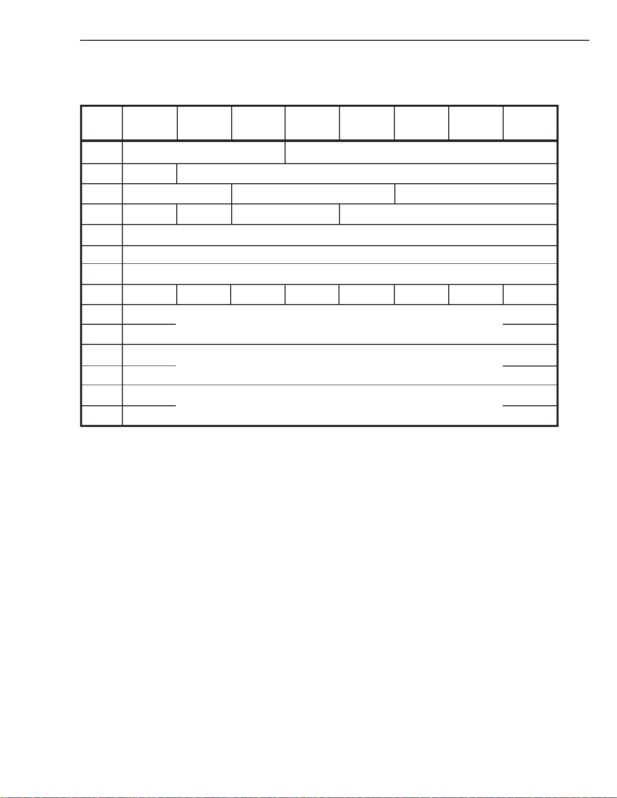
6. COMMAND SPECIFICATION
The drive returns the standard INQUIRY data as described below.
Bit76543210
Byte
0 Peripheral Qualifier Peripheral Device Type (01h)
1 RMB (1) Device-Type Modifier (0)
2 ISO Version (0) ECMA Version (0) ANSI-Approved Version (2)
3 AENC (0) TrmIOP Reserved (0) Response Data Format (2)
4 Allocation Length (1Fh)
5 Reserved
6 Reserved
7 RelAdr (0) WB32 (0) WB16 (0) Sync (1) Linked (0) Reserved CmdQ (0) SftRe (0)
8 (MSB) Vendor Identification
INQUIRY
15 (SONY) (LSB)
16 (MSB) Product Identification
31 (SDT-10000/SDT-11000) (LSB)
32 (MSB)
35 (LSB)
Product Revision Level
Table 6-2: INQUIRY Data
Peripheral Qualifier and Peripheral Device Type:
These fields identify the device that is currently connected to the logical unit. The drive is a single target, single
logical unit device. The logical unit number is set to zero. Therefore, the drive normally returns Peripheral Qualifier set to 000b the specified peripheral device type is currently connected to this logical unit and Peripheral Device
Type set to 01h sequential-access device. However, if the initiator requests a logical unit number greater than zero,
the drive returns Peripheral Qualifier set to 011b the target is not capable of supporting a physical device on this
logical unit and Peripheral Device Type set to 1Fh unknown device type.
SONY SDT-10000/SDT-11000 DDS Tape Drive
6 - 7
Page 59

6. COMMAND SPECIFICATION
RMB:
The Removable Medium bit is one, indicating that the tape can be removed.
Device-Type Modifier:
This is a seven-bit user defined code, set to 00h.
ISO Version:
This field is zero, indicating that the drive does not necessarily comply with the ISO version of SCSI.
ECMA Version:
This field is zero, indicating that the drive does not necessarily comply with the ECMA version of SCSI.
ANSI Approved Version:
This field is 2, indicating that the drive complies with the ANSI version of SCSI-2.
AENC:
The drive does not support asynchronous event notification, so this field is zero.
TrmIOP:
The drive does not support the Terminate I/O Process message so this field is zero.
Response Data Format:
This field is 2 indicating that the INQUIRY DATA format complies with the ANSI version of SCSI-2.
Additional Length:
The additional length field specifies the length in bytes of the parameters, in this case, 31 bytes.
RelAdr:
The drive does not support the Relative Addressing mode so this bit is never set.
WBus32:
The drive does not support 32-bit wide data transfers, so this bit is never set.
WBus16:
The drive does not support 16-bit wide data transfers, so this bit is never set.
Sync:
The drive supports synchronous data transfers, so this bit is set.
Linked:
The drive does not support linked commands, so this bit is never set.
CmdQue:
The drive does not support tagged command queuing, so this bit is never set.
SftRe:
The drive responds to the RESET condition with a HARD reset, so this bit is never set.
Vendor Identification:
This field contains eight bytes of ASCII data identifying the vendor of the product as “SONY”. This and the next
two fields are left-aligned with the unused bytes at the end of the fields and filled with space characters (20h).
Product Identification:
This field contains sixteen bytes of ASCII data identifying the product as “SDT-10000/SDT-11000”.
Product Revision Level:
This field contains four bytes of ASCII data, which define the SCSI Interface Revision Level.
INQUIRY
6 - 8
SONY SDT-10000/SDT-11000 DDS Tape Drive
Page 60
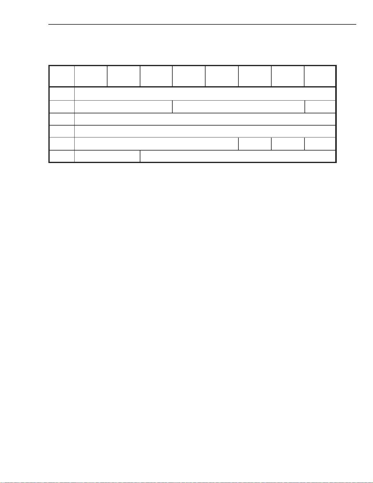
6. COMMAND SPECIFICATION
6. 03 LOAD/UNLOAD 1Bh
Bit76543210
Byte
0 Operation Code (1Bh)
1 Logical Unit Number Reserved Immed
2 Reserved
3 Reserved
4 Reserved EOT Re-Ten Load
5 Unused (00b) Reserved
LOAD/UNLOAD allows the host to tell the drive to enable or disable the media for further operations.
Load:
When this bit is set, the drive loads the tape and positions it at the beginning of Partition 0. The load command is
used when the tape has been retained in the drive by the command sequence, PREVENT ALLOW MEDIA REMOVAL (with prevent bit set), UNLOAD. The drive will automatically perform a Load operation when a tape is
inserted, a SCSI Reset is received, or when power is restored with a tape in the drive.
If the bit is not set (UNLOAD), the drive writes any buffered data to the tape, writes the EOD, then rewinds the tape
to BOM and ejects it.
Immed:
If this bit is set, status is returned as soon as the load or unload operation is initiated. Otherwise, the status is
returned after the operation has completed.
Re-Ten:
If this bit is set, the drive winds to EOM then rewinds to BOM before starting a normal loading sequence.
LOAD/UNLOAD
SONY SDT-10000/SDT-11000 DDS Tape Drive
6 - 9
Page 61

6. COMMAND SPECIFICATION
EOT:
An end-of-tape (EOT) bit of one and a Load bit of zero indicates that the medium shall be positioned at end-ofmedium for removal from the peripheral device. Prior to performing the unload operation, any buffered data that is
to be written shall be transferred to the medium.
An EOT bit of zero and Load bit of zero indicates that the medium shall be positioned at beginning-of-medium for
removal etc.
An EOT bit of one and a Load bit of one shall cause the target to return CHECK CONDITION status. The sense key
shall be set to ILLEGAL REQUEST and the additional sense code shall be set to ILLEGAL FIELD IN CDB.
If the drive has received an UNLOAD command with the Immediate bit set and then receives either another command
which would involve tape motion or TEST UNIT READY, the drive will return a CHECK CONDITION status with a
NOT READY sense key set.
When the drive receives the UNLOAD, it updates the System area of whichever partition on the tape is currently active.
The tape is then rewound to BOM and ejected. The operator must reload the drive manually. If, however, the drive has
previously received a PREVENT MEDIA REMOVAL (with prevent bit set) command, the tape is retained in the drive.
A subsequent LOAD command will load and position the tape at BOP zero. If an UNLOAD were sent instead, the drive
would return NOT READY and the tape would remain within the drive. In this case, the drive requires an PREVENT
ALLOW MEDIA REMOVAL (with prevent bit clear) command before an UNLOAD will eject the tape.
LOAD/UNLOAD
Note: While the PREVENT MEDIA REMOVAL is in effect, the Front Panel EJECT button is completely disabled.
If the cassette is unloaded but has not been ejected from the drive because of moisture detection, then a subsequent
UNLOAD will cause the tape to ejected from the drive. All commands except INQUIRY, REQUEST SENSE and
READ BLOCK LIMITS will return a CHECK CONDITION status with a HARDWARE ERROR sense key set. The
tape may also be ejected via the Front Panel EJECT button.
If no cassette is in drive, both LOAD and UNLOAD will return a CHECK CONDITION status with NOT READY
sense key set.
6 - 10
SONY SDT-10000/SDT-11000 DDS Tape Drive
Page 62
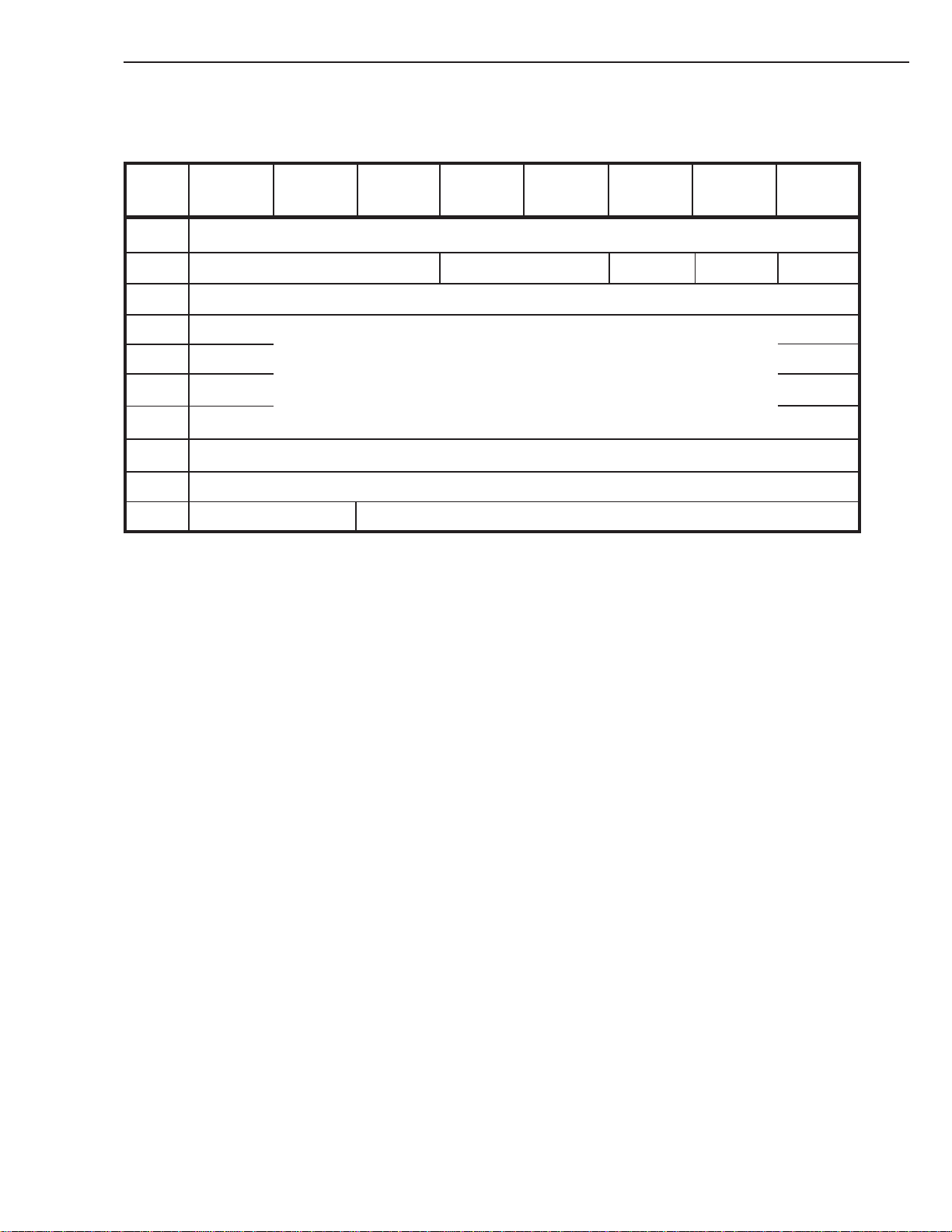
6. COMMAND SPECIFICATION
6. 04 LOCATE 2Bh
Bit76543210
Byte
0 Operation Code (2Bh)
1 Logical Unit Number Reserved BT (0) CP Immed
2 Reserved
3 (MSB)
4 Block Address
5
6 (LSB)
7 Reserved
8 Partition
LOCATE
9 Unused (00b) Reserved
LOCATE command causes the target to position the logical unit to the specified block address in a specified partition.
Upon completion, the logical position shall be before the specified location. Prior to performing the locate operation, the
target shall ensure that all buffered data, filemarks, and setmarks have been transferred to the medium.
BT: A block address type (BT) bit=1 is not supported and shall be set to zero otherwise a CHECK CONDITION with
an ILLEGAL REQUEST sense key will be returned.
CP: A change partition (CP) bit of one indicates that a change to the partition specified in the partition field is to occur
prior to positioning to the block specified in the block address field. A CP bit of zero indicates no partition change
is to be made and the partition field is to be ignored.
Immed:
An immediate (Immed) bit of zero indicates that the target shall not return status until the locate operation has
completed. An Immed bit of one indicates that the target shall return status as soon as all buffered commands have
completed execution and the command descriptor block of the LOCATE command has been validated. If CHECK
CONDITION status is returned for a LOCATE command with an Immed bit of one, the locate operation shall not be
performed.
Block Address:
The Block Address field specifies the block address to which the target shall position the medium based on the
current setting of the BT bit.
Partition:
The Partition field specifies which partition to select if the CP bit is one. Refer to the MODE SELECT command,
Medium Partition page for additional information about partitioning.
SONY SDT-10000/SDT-11000 DDS Tape Drive
6 - 11
Page 63
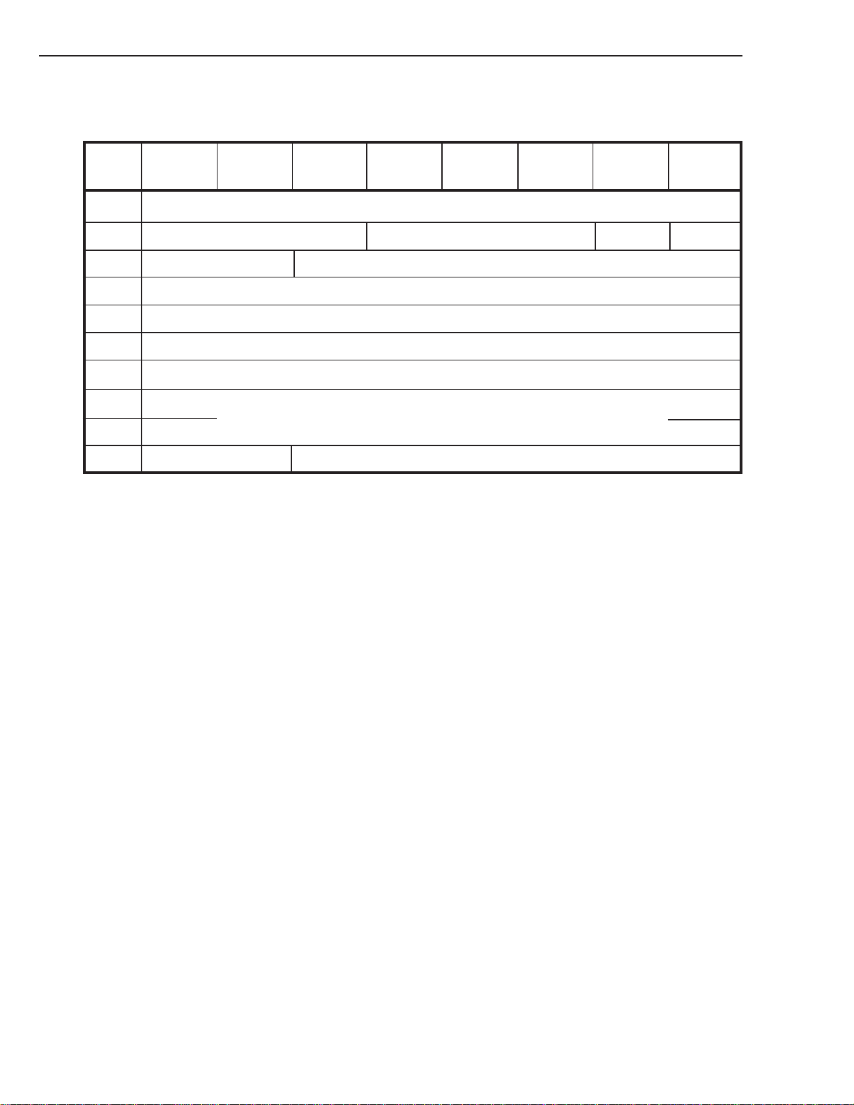
6. COMMAND SPECIFICATION
6. 05 LOG SELECT 4Ch
Bit76543210
Byte
0 Operation Code (4Ch)
1 Logical Unit Number Reserved PCR SP (0)
2 PC Reserved
3 Reserved
4 Reserved
5 Reserved
6 Reserved
7 (MSB)
8 (LSB)
LOG SELECT
Parameter List Length
9 Unused (00b) Reserved
The LOG SELECT command provides a means for the Host to manage statistical information maintained by the device
about its own hardware or the installed media. This description should be read in conjunction with the description of the
LOG SENSE command which follows it, to provide the reader with information about log page format, parameters and
supported pages.
PCR:
A Parameter Code Reset bit of one and a Parameter List Length of zero will cause ALL log pages which can be
cleared, to be cleared. If this field is set and the Parameter List Length field is non-zero then the command will be
terminated with a CHECK CONDITION status with the sense key set to ILLEGAL REQUEST, and an additional
sense code of INVALID FIELD IN CDB.
SP: The device does not have non-volatile RAM into which it may save parameters. Therefore, the Save Page bit is not
supported by this device and shall always be set to zero. If the SP bits is set, the command will be terminated with
CHECK CONDITION status with the sense key set to ILLEGAL REQUEST, and an additional sense code of
INVALID FIELD IN CDB.
6 - 12
SONY SDT-10000/SDT-11000 DDS Tape Drive
Page 64

6. COMMAND SPECIFICATION
PC: The Page Control field defines the type of parameter values to be selected:
Value Type of Parameter Values
00b Current Threshold Values
01b Current Cumulative Values
10b Default Threshold Values
11b Default Cumulative Values
LOG SELECT
Table 6-3: Page Control field values
If this field is set to 00b, 10b or 11b and the Parameter List Length field is non-0 then the command will be terminated
with a CHECK CONDITION status with the sense key set to ILLEGAL REQUEST, and an additional sense code of
INVALID FIELD IN CDB. This is because no modification of these log pages are permitted.
For a description of command action if this field is set to 01b then see the description of the Parameter List Length field
below.
If this field is set to 10b and the Parameter List length field is 0 then all Current Threshold Values will be reset to the
Default Threshold Values. This equivalent to no change as Threshold Values cannot be modified.
If this field is set to 11b and the Parameter List Length field is 0 then all Current Cumulative Values will be reset to the
Default Cumulative Values.
This is equivalent to all log pages which can be cleared.
Parameter List Length:
This field specifies the length in bytes of the LOG SELECT parameter list that shall be transferred from the initiator to
the target during the DATA OUT phase. A parameter list length of zero indicates that no data shall be transferred. This
condition shall not be considered as an error (see description of Parameter Code Reset and Page Control fields above). If
this field is non-0 the Page Control field must be 01b.
The purpose of the LOG SELECT command is to allow the initiator to modify and initialize parameters within the logs
supported by the device. However in this case, access to individual parameters within log pages is not supported and so
initiator is restricted to resetting complete log pages only.
SONY SDT-10000/SDT-11000 DDS Tape Drive
6 - 13
Page 65

6. COMMAND SPECIFICATION
To achieve this, during the DATA OUT phase the initiator must send the log page header of the page to be cleared, with
the Page Length field set to 0. The following pages can be cleared in this manner.
Note: Due to the way in which logs are stored and updated, clearing log page 2 will
result in log page 3 also being cleared and vice versa.
Because of this method of clearing the log pages, the Parameter List Length field must be an integer multiple of the Log
Page Header length (i.e. 4). Otherwise the command will be terminated with a CHECK CONDITION status with the
sense key set to ILLEGAL REQUEST and an additional sense code of INVALID FIELD IN CDB.
If multiple pages are sent during this DATA OUT phase then they must be sent in ascending order according to page
code. Otherwise the command will terminate with a CHECK CONDITION status with the sense key set to ILLEGAL
REQUEST and an additional sense code of ILLEGAL FIELD IN PARAMETER LIST. The same status will be returned if an unsupported Page Code appears in any header or if the specified page cannot cleared.
LOG SELECT
Page Code Description
02h Write Error Counter Page
03h Read Error Counter Page
07h Last n Error Events Page
Table 6-4: Page Codes
6 - 14
SONY SDT-10000/SDT-11000 DDS Tape Drive
Page 66
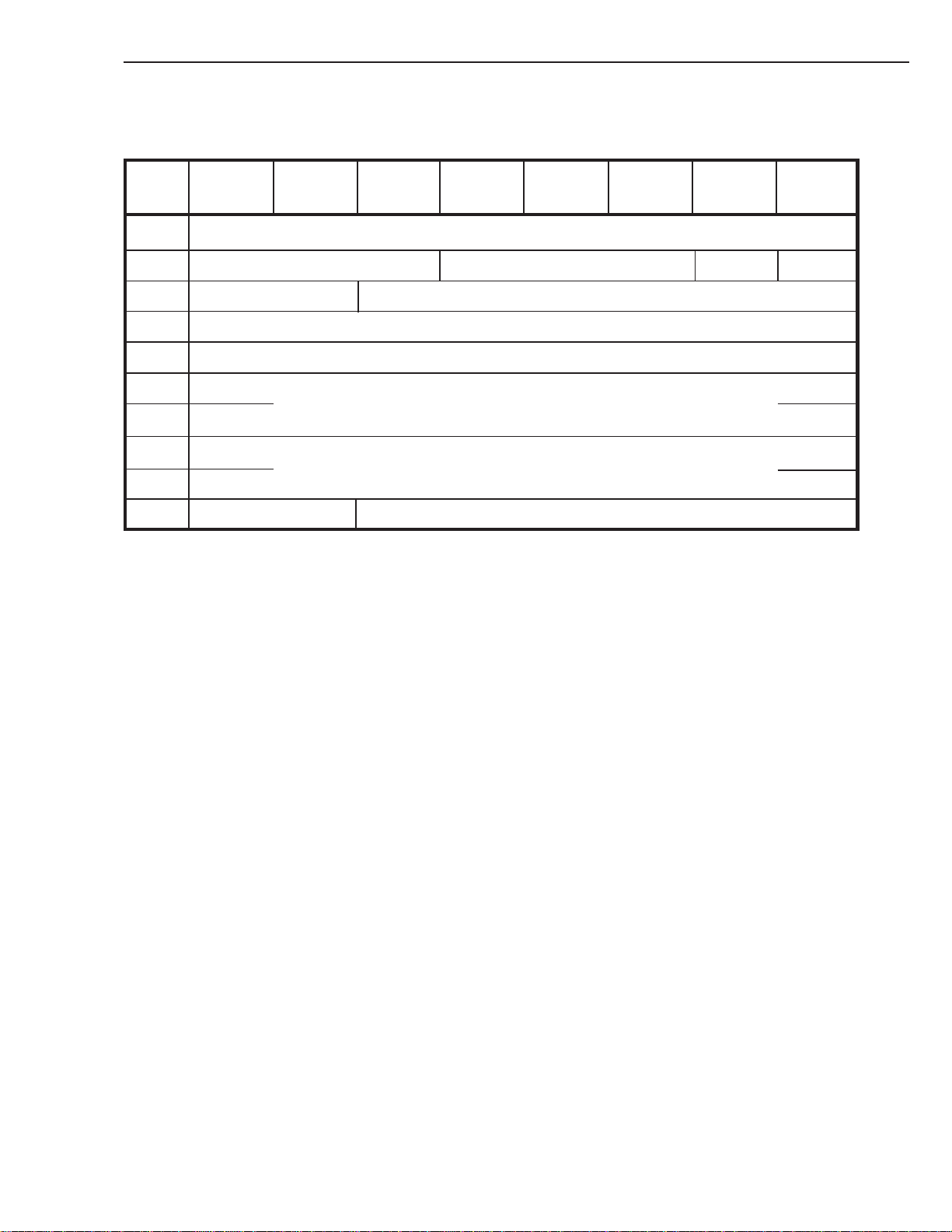
6. COMMAND SPECIFICATION
6. 06 LOG SENSE 4Dh
Bit76543210
Byte
0 Operation Code (4Dh)
1 Logical Unit Number Reserved PPC (0) SP (0)
2 PC Page Code
3 Reserved
4 Reserved
LOG SENSE
5 (MSB)
6 (LSB)
7 (MSB)
8 (LSB)
9 Unused (00b) Reserved
LOG SENSE provides a means for the Host to retrieve statistical information maintained by the device about its own
hardware or the installed media. It is a complementary command to the LOG SELECT command.
SP: The device does not have non-volatile RAM into which it may save parameters. Therefore, the Save Page bit is not
supported by this device and shall always be sent to zero. If the SP bit is set, the command will be terminated with
CHECK CONDITION status with the sense key set to ILLEGAL REQUEST, and an additional sense code of
INVALID FIELD IN CDB.
Parameter Pointer
Allocation Length
SONY SDT-10000/SDT-11000 DDS Tape Drive
6 - 15
Page 67

6. COMMAND SPECIFICATION
PPC:
The Parameter Pointer Control bit shall always be set to zero. This indicates that the parameter data requested from
the device will start with the parameter code specified in the Parameter Pointer field and return the number of bytes
specified in the Allocation Length field in ascending order of parameter codes from the specified log page. A PPC
bit of zero and a Parameter Pointer field of zero cause all available parameter data for that page code to be returned
to the initiator.
If the PPC bit is set or the Parameter Pointer is larger than the highest numbered parameter on the page, then the
target shall terminate the command with CHECK CONDITION status. The sense key shall be set to ILLEGAL
REQUEST and the additional sense code shall be set to INVALID FIELD IN CDB.
If the drive does not support a parameter code within this page then it shall not return any data associated with this
parameter.
PC: The Page Control field defines the type of parameter values to be selected. The page control field is defined below:
LOG SENSE
Value
00b
01b
10b
11b
Type of Parameter Values
Current Threshold Values
Current Cumulative Values
Default Threshold Values
Default Cumulative Values
Table 6-5: Page Control field values
The Current Threshold Values and the Default Threshold Values are non-changeable and will both return the same
values - i.e. the maximum values that each parameter can attain. Note that for some parameters the term threshold value
has no meaning. See the description of individual pages/parameters below for more details.
The Current Cumulative Values are the values computed since the last reset of the device (either by power-cycling, BUS
DEVICE RESET or SCSI RESET). Note that for some parameters these values cannot be reset by any method. See
description of individual pages/parameters below for more details.
The Default Cumulative Values are the values to which each parameter gets initialized on a reset condition as described
above. See description of individual pages/parameters below for more details.
6 - 16
SONY SDT-10000/SDT-11000 DDS Tape Drive
Page 68

6. COMMAND SPECIFICATION
Page Code:
The Page Code field identifies which log page is being requested by the initiator.
If the page is not supported then the command will terminate with a CHECK CONDITION status with the sense key
set to ILLEGAL REQUEST and an additional sense code of INVALID FIELD IN CDB. Supported pages are:
Page Code Description Allocation Length
00h Supported Log Pages 0Ch
02h Write Error Counter Page 20h
03h Read Error Counter Page 20h
07h Last n Error Events Page
30h Tape Log Page (Sony Unique)
31h Tape Capacity Log Page 24h
33h Drive Usage Page (Sony Unique)
39h Data Compression Transfer Log Page 5Ch
1A8h (max)
5Ch
5Eh (DDS-3 and DDS-4)
154h
LOG SENSE
Table 6-6: Supported Log Pages
Parameter Pointer:
The Parameter Pointer field allows the host to specify at which parameter within a log page the requested data
should begin.
For example if a page supported parameters 0 through 5, and the Parameter Pointer field contained 3 then only
parameters 3, 4 and 5 would be returned to the initiator. Similarly, if a page supported parameters 1, 3 and 6, and the
Parameter Pointer field contained 2, then only parameters 3 and 6 would be returned to the initiator.
Note that parameters within a page are always returned in ascending order according to parameter code. If an
invalid parameter pointer is sent the drive will return CHECK CONDITION with the sense key set to ILLEGAL
REQUEST and an additional sense code of INVALID FIELD IN CDB.
Allocation Length:
The Allocation Length field is used to inform the target how much space the initiator has allocated for data. There
must be sufficient space allocated for all the requested data. If there isn’t then the command will terminate with a
CHECK CONDITION status with the sense key set to ILLEGAL REQUEST and an additional sense code of
INVALID FIELD IN CDB. Note however that if this field is 0 then this is not considered an error and the device
will just return a GOOD status.
SONY SDT-10000/SDT-11000 DDS Tape Drive
6 - 17
Page 69
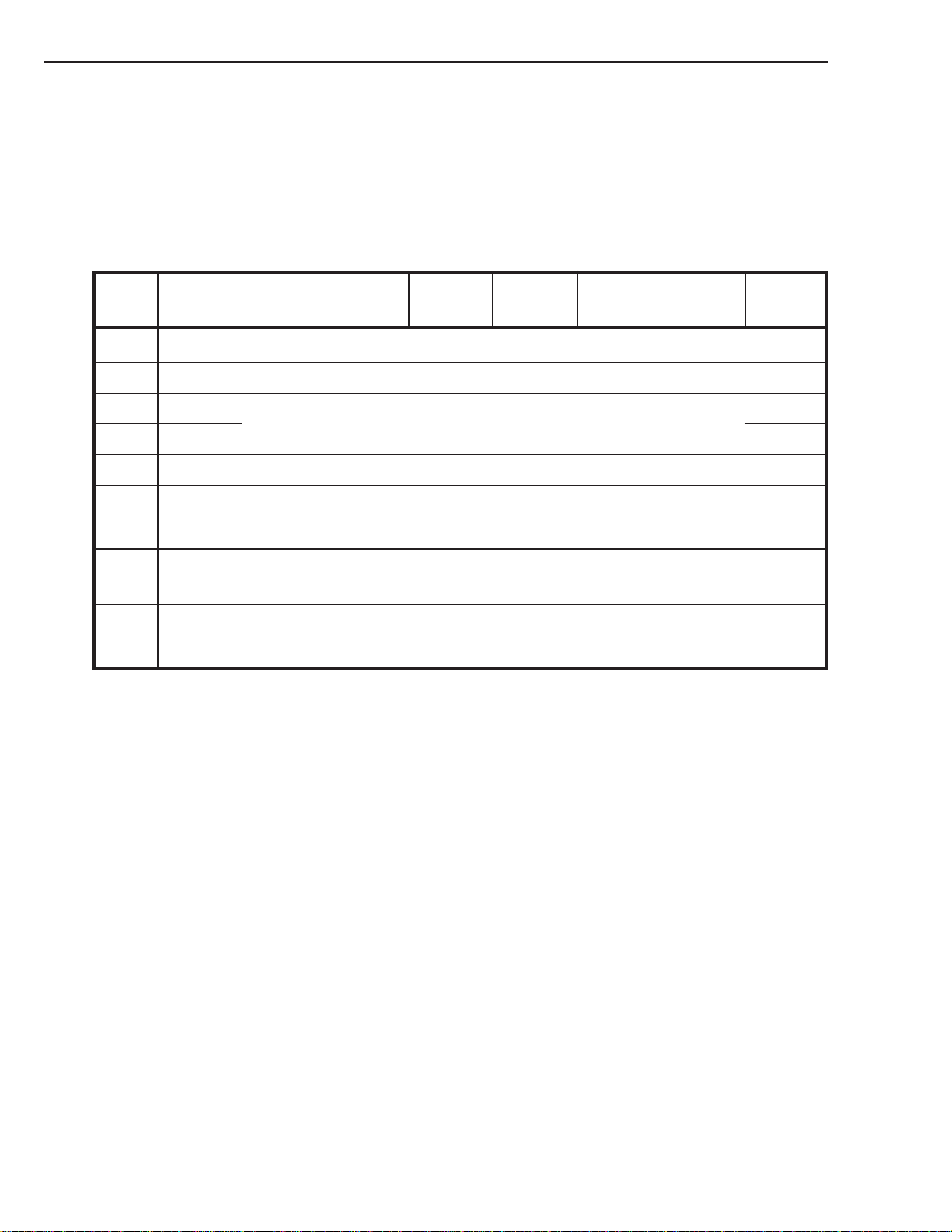
6. COMMAND SPECIFICATION
6. 06. 1 The Log Page Descriptor
The format of the log pages consists of zero or more variable-length parameter structures. Each page begins with a 4byte page header followed by zero or more variable-length parameter structures defined for that page. The Log Select
command supports the ability to send zero or more log pages. The LOG SENSE command returns a single log page as
specified in the Page Code field of the CDB.
Bit76543210
Byte
0 Reserved Page Code
1 Reserved
LOG SENSE
2 (MSB)
3 (LSB)
4- Log Parameter (First)
x+3 (Length x)
n-y Log Parameter (Last)
n (Length y)
Page Length (n-3)
Log Parameters (s)
•
•
•
Table 6-7: Log Page Format
Page code:
Identifies which page of data is being transferred. If the Page Code field value is reserved or not implemented by the
target, the target shall terminate the command with a CHECK CONDITION status. The sense key shall be set to
ILLEGAL REQUEST, and the additional sense code shall be set to INVALID FIELD IN PARAMETER LIST.
6 - 18
Page Length:
Defines the length, in bytes, of the following log parameters. This length does not include bytes zero through three.
A Page Length value that results in the truncation of any parameter shall cause the target to terminate the command
with CHECK CONDITION status. The sense key shall be set to ILLEGAL REQUEST and the additional sense
code shall be set to INVALID FIELD IN PARAMETER LIST.
SONY SDT-10000/SDT-11000 DDS Tape Drive
Page 70
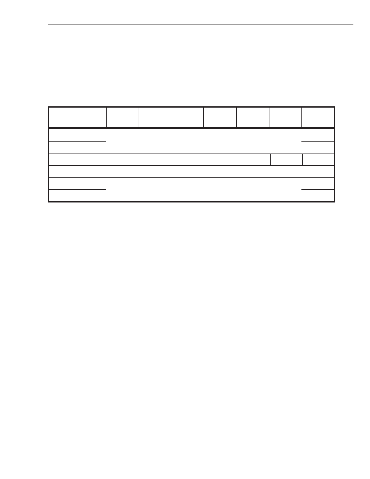
6. COMMAND SPECIFICATION
6. 06. 2 The Log Parameter Descriptor
Most log pages contain one or more special data structures called log parameters. These may be data counters which
record the occurrence of certain events, or they may be more complex structures which describe activities or other events
which occur within the device. Each parameter structure begins with a 4-byte parameter header followed by one or more
bytes of parameter structure data. The 4-byte header is shown below:
Bit76543210
Byte
0 (MSB) Parameter Code
1 (LSB)
2 DU DS (1) TSD ETC TMC Reserved LP
3 Parameter Length (n-3)
LOG SENSE
4
n
Parameter Value
Table 6-8: Log Parameter
Parameter Code:
Identifies which parameter of data is being transferred. If the parameter code value is reserved or not implemented
by the target, then the target shall terminate the command with CHECK CONDITION status. The sense key shall be
set to ILLEGAL REQUEST and the additional sense code shall be set to INVALID FIELD IN PARAMETER
LIST.
The DU, DS, TSD, ET, TMC, and LP fields are collectively referred to as the control byte.
DU: The DU bit (Disable Update) is not defined for threshold values (indicated by the PC field of the LOG SENSE
command descriptor block). The target shall ignore the value of any DU bits in a LOG SELECT command.
DS: The DS bit-field informs the initiator that savable parameters are disabled (i. e. not supported), and should always
be 1. If it is 0 the command will terminate with CHECK CONDITION status with sense key set to ILLEGAL
REQUEST and additional sense code of ILLEGAL FIELD IN PARAMETER LIST.
SONY SDT-10000/SDT-11000 DDS Tape Drive
6 - 19
Page 71

6. COMMAND SPECIFICATION
TSD:
A target save disable (TSD) bit of zero indicates a target-defined method for saving log parameters. This implicit
saving operation shall be done frequently enough to insure that the cumulative parameter values retain statistical
significance (i.e. across power cycles). A TSD bit of one indicates that either the target does not provide a targetdefined method for saving log parameters or the target-defined method has been disabled by the initiator. If the
initiator sets both the DS and the TSD bits set to one, the target shall terminate the command with CHECK CONDITION status. The sense key shall be set to ILLEGAL REQUEST with the additional sense code set to INVALID
FIELD IN PARAMETER LIST.
ETC:
This bit is not supported by this device.
An enable threshold comparison (ETC) bit of one indicates that when the cumulative parameter value is updated, it
shall be compared to the threshold parameter value and the action specified by the TMC field shall be taken. An
(ET) bit of zero disables this comparison. The ET bit is the same for both the cumulative and threshold log parameter. Thus when the ET bit is set to a value by the initiator, this value is returned for both the cumulative and
threshold values of the log parameter.
LOG SENSE
TMC:
This bit is not supported by this device.
The threshold met criteria (TMC) field defines the binary relationship between the cumulative and threshold log
parameter values under which the threshold is met. If the ET bit is one and the threshold condition is met, a Unit
Attention condition shall be posted to all initiators. When reporting the unit attention condition, the target shall set
the sense key to UNIT ATTENTION, the additional sense code to LOG EXCEPTION, and the additional sense
code qualifier to THRESHOLD CONDITION MET.
TMC
00b
01b
10b
11b
Threshold Met Criteria
Any update of the parameter
Cumulative = Threshold
Cumulative < > Threshold
Cumulative > Threshold
Table 6-9: Threshold Met criteria
The TMC field is the same for both the cumulative and threshold parameter. Thus when the TMC field is set to a value
by the initiator, this value is returned for both cumulative and threshold values of the log parameter.
LP: The LP bit field defines whether the parameter is a data counter or a list parameter. An LP bit of one indicates that
the parameter is a list Parameter. An LP bit of Zero indicates that the parameter is a data counter. See the description of each supported page below for information on the setting of this field.
6 - 20
Note: If any of the other bit-fields in the control byte are set then the command will terminate with a CHECK CONDI-
TION status with a sense key of ILLEGAL REQUEST and an additional sense code of INVALID FIELD IN
PARAMETER LIST.
SONY SDT-10000/SDT-11000 DDS Tape Drive
Page 72
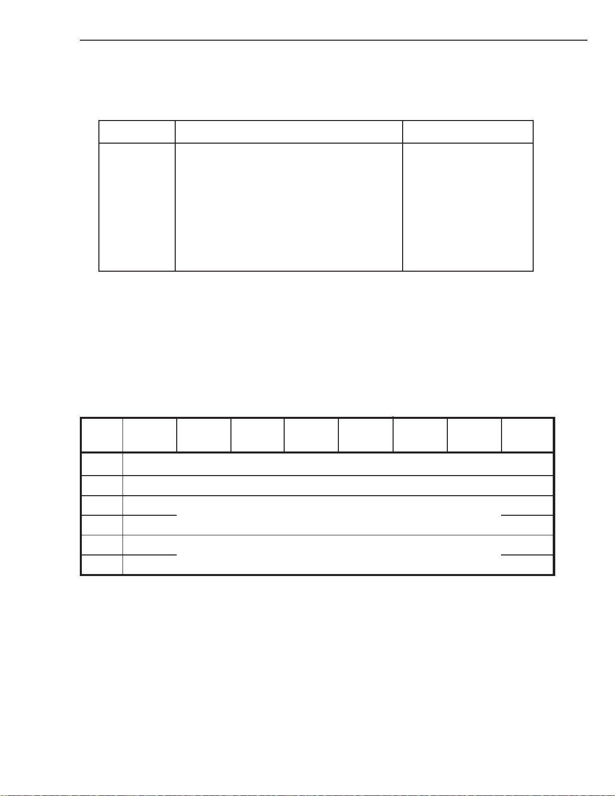
6. COMMAND SPECIFICATION
6. 06. 3 Supported Log Pages
The following log pages are supported:
Page Code Description Allocation Length
00h Supported Log Pages 0Ch
02h Write Error Counter Page 20h
03h Read Error Counter Page 20h
07h Last n Error Events Page
30h Tape Log Page (Sony Unique) 5Ch
31h Tape Capacity Log Page 24h
33h Drive Usage Page (Sony Unique)
39h Data Compression Transfer Log Page 5Ch
Table 6-10: Supported Log pages
A description of each supported log page is given below.
LOG SENSE
1A8h (max)
5Eh (DDS-3 and DDS-4)
154h
6. 06. 3. 1 Summary List of Supported Pages
The summary list of supported log pages returns the list of page codes supported by the target. This page is only valid
for the Log Sense command and if sent to the host during a Log Select command will cause termination with CHECK
CONDITION status with sense key set to ILLEGAL REQUEST and additional sense code of INVALID FIELD IN
PARAMETER LIST.
Bit76543210
Byte
0 Page Code (00h)
1 Reserved
2 (MSB)
3
4 Supported Page List
C (00 02 03 07 2E 30 31 33 39h)
Page Length (00 08h)
(LSB)
Table 6-11: Supported Log Pages
This page returns the summary list of supported log pages for the specified logical unit to the requesting initiator.
SONY SDT-10000/SDT-11000 DDS Tape Drive
6 - 21
Page 73

6. COMMAND SPECIFICATION
IMPLEMENTORS NOTE:
Typically, an initiator should first request page zero to determine the list of pages supported by the device.
The page code parameters are a list containing the page codes of the supported pages for the logical unit in ascending
order.
Note that neither Threshold nor Cumulative values have any meaning for this page.
6. 06. 4 Write and Read Error Counters Pages
The Error Counters Pages (Write and Read) are used to report statistical information about Write and Read soft and hard
errors and retries. Each parameter is a counter which is updated by the target every time the corresponding event occurs.
The format of the Error Counters Pages is given below:
Bit76543210
Byte
0 Page Code (02h or 03h)
1 Reserved
LOG SENSE
2 (MSB)
3 (LSB)
4 (MSB)
5 (LSB)
6 DU (0) DS (1) TSD (0) ETC (0) TMC (00) Reserved LP (0)
7 Parameter Length (m)
8 (MSB)
n (LSB)
Page Length (n)
Parameter Code
Parameter Value
Table 6-12: Write/Read Error counters page
6 - 22
SONY SDT-10000/SDT-11000 DDS Tape Drive
Page 74

6. COMMAND SPECIFICATION
The Page Code is one of the following:
LOG SENSE
Page Code
02h
03h
Description
Write Error Counter Page
Read Error Counter Page
Table 6-13: Page Code
The following parameter codes are supported for each Error Counters Page:
Parameter Description Parameter Default Default
Code Length (Bytes) Cumulative Threshold
0003h Total Errors Corrected 2 0 FFFFh
(Soft Errors)
0004h Total T imes Correction 4 0 FFFFFFFFh
Algorithm Processed
0005h Total Groups Processed
0006h Total Errors Uncorrected
(Hard Errors)
4
2 0 FFFFh
0 FFFFFFFFh
Table 6-14: Error Counter parameter codes
SONY SDT-10000/SDT-11000 DDS Tape Drive
6 - 23
Page 75
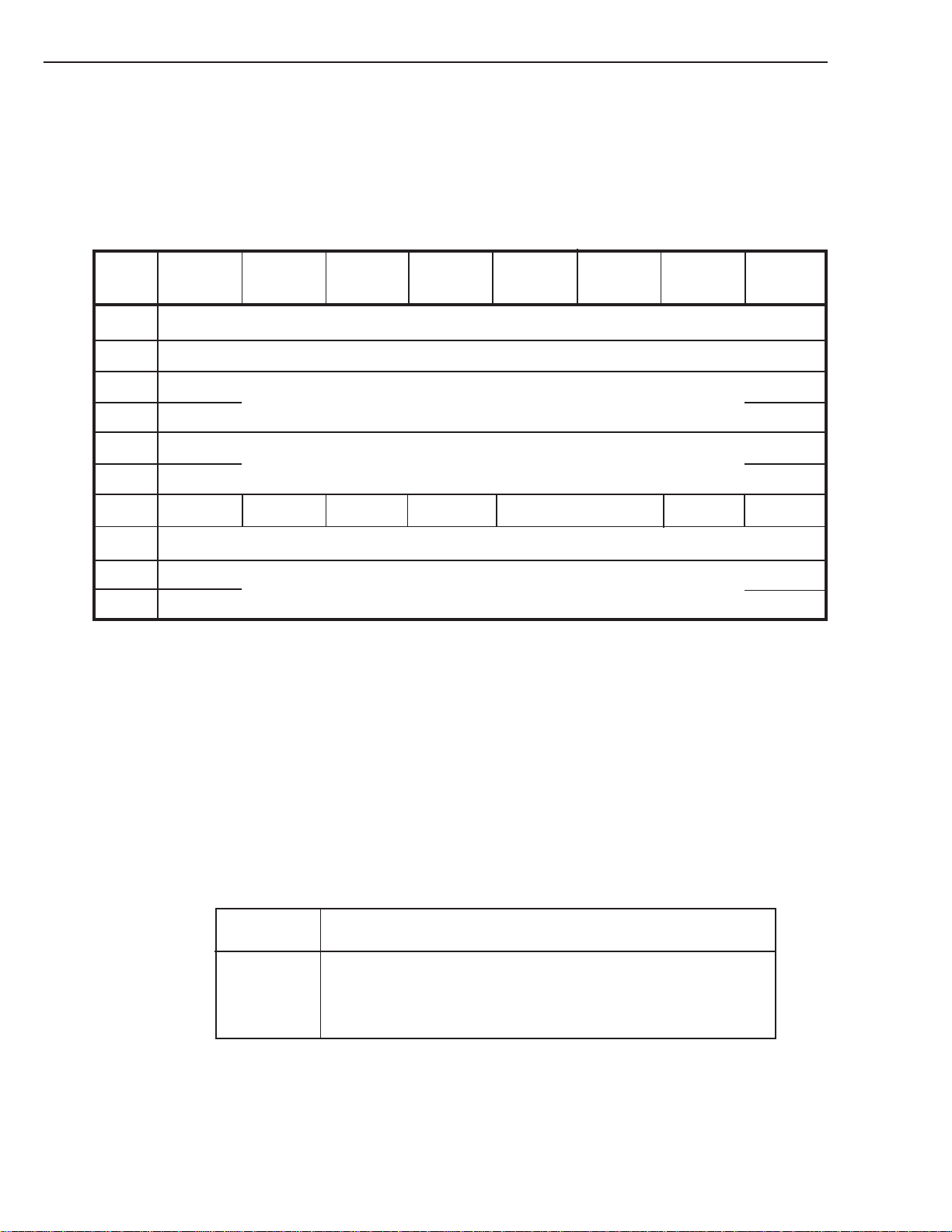
6. COMMAND SPECIFICATION
6. 06. 5 Last N Error Events List
This page is used to report information on soft and hard errors encountered by the device during normal operation. Each
parameter corresponds to an encountered error and is a report of what type of error occurred and when it occurred. The
format of the page is given below:
Bit76543210
Byte
0 Page Code (07h)
1 Reserved
LOG SENSE
2 (MSB)
3 (LSB)
4 (MSB)
5 (LSB)
6 DU (0) DS (1) TSD (0) ETC (0) TMC (00) Reserved LP (1)
7 Parameter Length (0Ah)
8
17
Page Length (n*14)
Parameter Code
Parameter Value
Table 6-15: Last N Error Events Page
The Parameter Codes supported are 1 through 30 where 30 is the maximum number of entries in the log page.
If there are no entries, the command will return the Page Header with the Page Length field set to 0.
Each error event record contains diagnostic information for a single error encountered by the device. The parameter
codes associated with the error-event records indicate the order in which the errors occurred. A higher parameter code
indicates that the error event occurred later in time.
6 - 24
Each parameter entry is 10 bytes long and has the following format:
Byte Offset
0 - 4
5
6 - 9
Meaning
Result Message (see Diagnostic Section)
Unused
Timestamp (number of 50 ms increments since power-on)
Table 6-16: Error Event format
When the log page becomes full, no more entries will be added until the log is cleared (using one of the methods
described previously) or a reset occurs. The current cumulative values will be returned regardless of the page control
field in the LOG SENSE CDB.
SONY SDT-10000/SDT-11000 DDS Tape Drive
Page 76
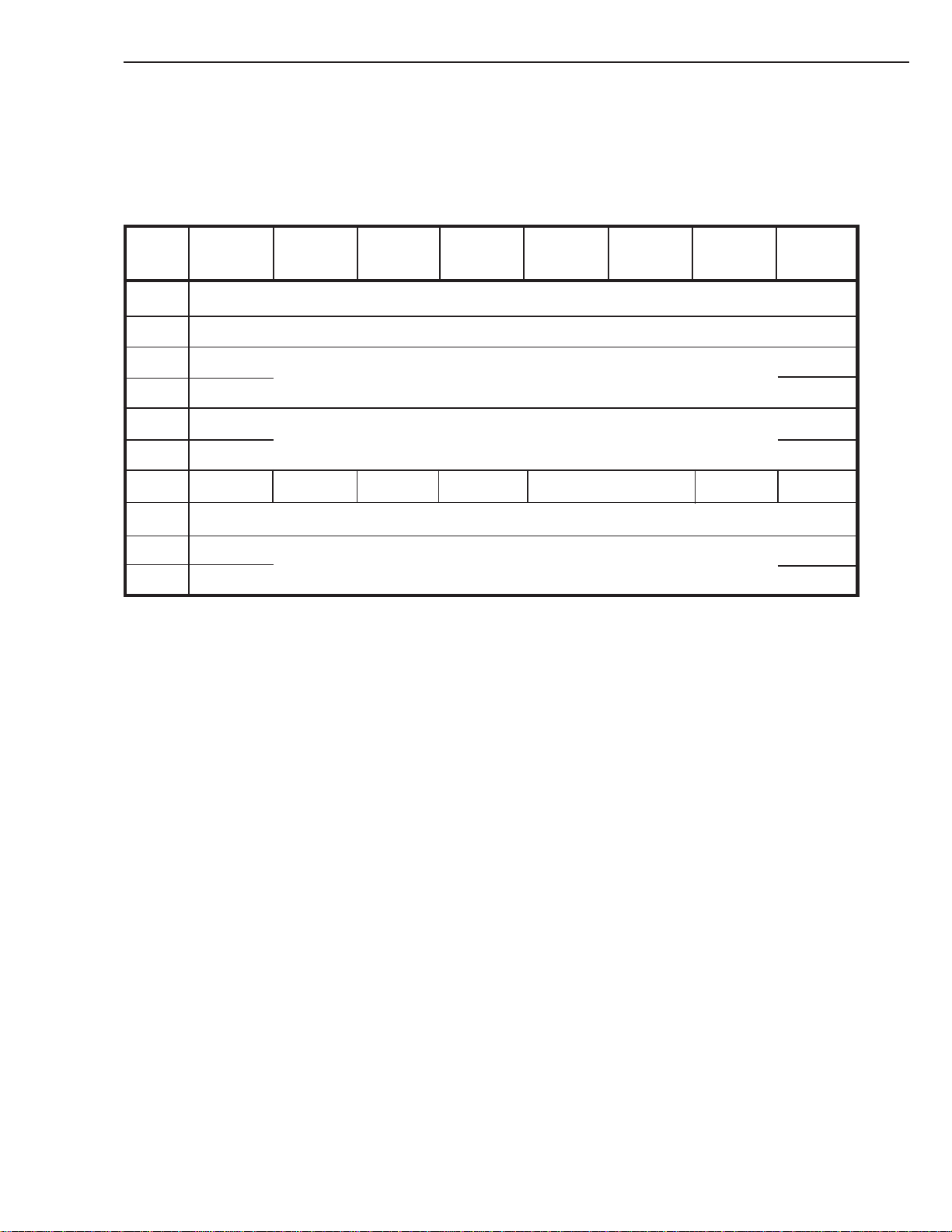
6. COMMAND SPECIFICATION
6. 06. 6 Tape Log Page (Sony Unique)
This page is a Sony unique page which provides information on the tape currently being used. This log cannot be cleared
and has the following format:
Bit76543210
Byte
0 Page Code (30h)
1 Reserved
2 (MSB) Page Length (58h)
3 Page Length (5Ah) (DDS-3 and DDS-4) (LSB)
LOG SENSE
4 (MSB)
5 (LSB)
6 DU (0) DS (1) TSD (0) ETC (0) TMC (00) Reserved LP (0)
7 Parameter Length (m)
8
3+m
Parameter Code
Parameter Value
Table 6-17: Tape Log Page
This page is used to return Tape Log information to the host in a format which conforms to the LOG SENSE command
page format.
SONY SDT-10000/SDT-11000 DDS Tape Drive
6 - 25
Page 77

6. COMMAND SPECIFICATION
Supported Parameter Codes in this page are listed below along their meanings:
Parameter Code Description Length
001h Current number of Groups Written 3
002h Current number of RAW Retries 2
003h Current number of Groups Read 3
004h Current number of ECC-3 Retries 2
005h Previous number of Groups Written 3
006h Previous number of RAW Retries 2
007h Previous number of Groups Read 3
008h Previous number of ECC-3 Retries 2
009h Total number of Groups Written 4
00Ah Total number of RAW Retries 3
00Bh Total number of Groups Read 4
00Ch Total number of ECC-3 Retries 3
LOG SENSE
4 (DDS-3 and DDS-4)
4 (DDS-3 and DDS-4)
00Dh Load Count 2
Table 6-18: Tape Log parameter codes
This information is contained within RAM in the Drive Controller. When a cassette is loaded, the contents of the
System Area are copied into this log. The log is updated as the tape is used and is copied back onto the System Area
when the cassette is unloaded (if the tape is Write enabled).
Note: The System Area only contains ‘previous’ and ‘total’ information - (when the cassette is unloaded, the ‘current’
values become the System Area ‘previous’ values).
The term ‘current’ refers to information generated during the current load of the tape; ‘previous’ refers to information
generated during the last tape load; ‘total’ refers to information generated during the life of the tape since it was first
initialized including the current load.
Use: An estimate of reading and writing performance can be made by the ratios of ‘RAW retries’ to ‘groups written’
and ‘ECC-3 retries’ to ‘groups read’. An indication of tape degradation can be gained by comparing these ratios
for ‘current’, ‘previous’ and ‘total’ entries.
Any attempt to change this page using LOG SELECT will result in a CHECK CONDITION with a Sense Key of
ILLEGAL REQUEST. The current cumulative values will be returned regardless of the Page Control field in the LOG
SENSE CDB.
6 - 26
SONY SDT-10000/SDT-11000 DDS Tape Drive
Page 78

6. COMMAND SPECIFICATION
6. 06. 7 Tape Capacity Log Page
The Tape Capacity Log Page is used to indicate the approximate capacity of the tape currently being used. The PC field
of the LOG SENSE command is ignored for this field.
The 36 bytes of the log page have the following format:
Bit76543210
Byte
0 Page Code (31h)
1 Reserved
LOG SENSE
2 (MSB)
3 (LSB)
4 (MSB)
5 (LSB)
6 DU (0) DS (1) TSD (0) ETC (0) TMC (11) Reserved LP (0)
7 Parameter Length (04h)
8 (MSB)
11 (LSB)
Page Length (20h)
Parameter Code
Parameter Value
Table 6-19: Tape Capacity Log Page
Tape Capacity Log Page Parameters:
Code Value
0001 Remaining capacity, partition 0 (kilobytes)
0002 Remaining capacity, partition 1 (kilobytes), For a single partition tape, it will be zero.
0003 Maximum capacity , partition 0 (kilobytes)
0004 Maximum capacity, partition 1 (kilobytes). For a single partition tape, it will be zero.
SONY SDT-10000/SDT-11000 DDS Tape Drive
6 - 27
Page 79
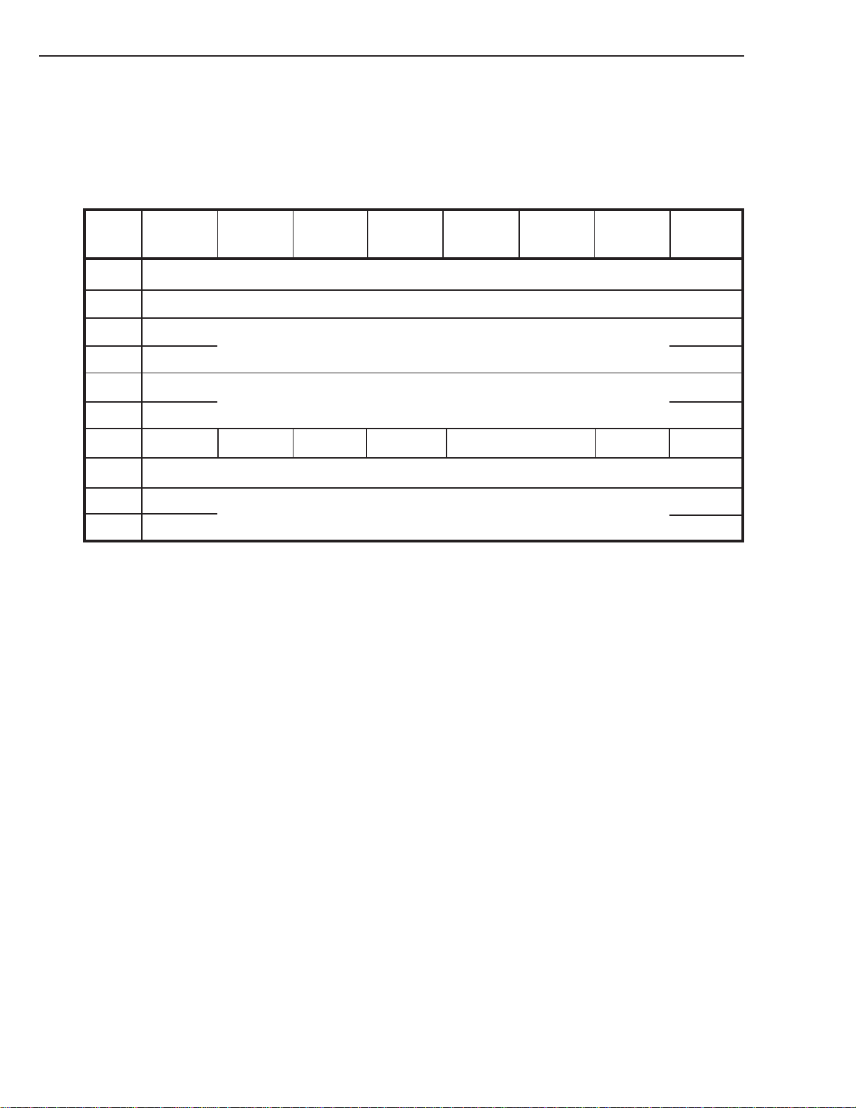
6. COMMAND SPECIFICATION
6. 06. 8 Drive Usage Log Page (Sony Unique)
This page is a SONY unique page which provides information on the drive currently being used. This log cannot be
cleared and has the following format:
Bit76543210
Byte
0 Page Code (33h)
1 Reserved
LOG SENSE
2 (MSB)
3 (LSB)
4 (MSB)
5 (LSB)
6 DU (0) DS (1) TSD (0) ETC (0) TMC (00) Reserved LP (0)
7 Parameter Length (m)
8
7+m
Page Length (150h)
Parameter Code
Parameter Value
Table 6-20: Drive Usage Log Page
This page is used to return the vendor unique Drive Usage Log information to the host in a format which conforms to the
Log Sense command page format.
6 - 28
SONY SDT-10000/SDT-11000 DDS Tape Drive
Page 80

6. COMMAND SPECIFICATION
Supported Parameter Codes in this page are listed below with their meaning:
Parameter Code Length (bytes)
0001h Drum revolution minute 3
0002h Load count 3
0003h Thread count 3
0004h Assert count 3
0005h Cleaning interval (minute) 3
0006h Power on time 3
0007h MD serial number 4
0008h PCB serial number 4
0009h Drive serial number 4
0011h - 2Eh Last 30 Mechanism Error Events List 5 x 30
Table 6-21: Supported Parameter Codes
LOG SENSE
Each Mechanism Error Event is 5 bytes long and has following format:
Byte offset Meaning
0 Error code
1 Executing Mechanism Commands when error was detected
2 - 4 Timestamp (minute)
Table 6-22: Mechanism Error Event Format
Executing Mechanism Commands
FWD ATF ON
FF
PAUSE
THREAD
TENSION OFF
RVS
REW
UNTHREAD
STOP
EJECT
MD INITIALIZE
0x01
0x07
0x0e
0x0f
0x10
0x11
0x17
0x20
0x21
0x22
0x2A
FWD
LOAD
RE TENSION
RESTART
STOP FF
STOP REW
ASSERT
RELEASE
RE ASSERT
STOP FWD
STOP RVS
0x30
0x31
0x32
0x33
0x34
0x35
0x36
0x37
0x38
0x39
0x3A
SONY SDT-10000/SDT-11000 DDS Tape Drive
6 - 29
Page 81
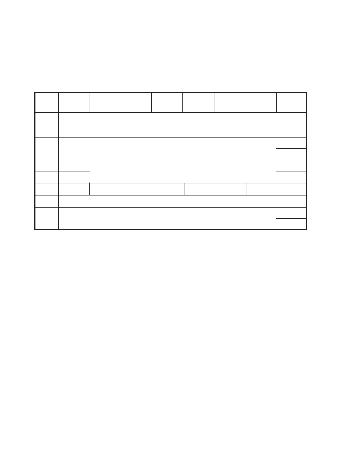
6. COMMAND SPECIFICATION
6. 06. 9 Data Compression Transfer Log Page
The page allows the host to monitor the performance of the DCLZ compression. The PC field in LOG SENSE determines whether current cumulative, default cumulative, or current/default threshold values are returned. The page has
the following format:
Bit76543210
Byte
0 Page Code (39h)
1 Reserved
LOG SENSE
2 (MSB)
3 (LSB)
4 (MSB)
5 (LSB)
6 DU (0) DS (1) TSD (0) ETC (0) TMC (00) Reserved LP (0)
7 Parameter Length (04h)
8 (MSB)
11 (LSB)
Page Length (58h)
Parameter Code (n)
Parameter Value
Table 6-23: Data Compression Transfer Log Page
6 - 30
SONY SDT-10000/SDT-11000 DDS Tape Drive
Page 82

6. COMMAND SPECIFICATION
Data Compression Log Page Fields:
Supported Parameter Codes in this page and their meanings are as follows:
Code Description
0001h Number of entities written
0002h Number of entities read
0003h Number of records written
0004h Number of records read
0005h Kilobytes to data compression
0006h Kilobytes from data compression
0007h Kilobytes to tape
0008h Kilobytes from tape
0009h Logical entity size
000Ah Physical entity size
000Bh Uncompressed entities
Entities Written/Read:
The total number of complete entities written to or read from the tape since the last power-on or Cleaner Log
operation.
Records Written/Read:
The total number of records (both compressed and uncompressed) written to or read from the tape since the last
power-on or Clear Log operation.
Kilobytes to/from Data Compression:
The total number of kilobytes written to or read from the tape since the last power-on or Clear Log operation. For
Kilobytes from Data Compression, this number may be greater than the number of kilobytes transferred to the host
due to readahead.
Logical Entity Size:
The logical size of the last entity written to or read from the tape:
size = number of records in entity x record size in bytes
Physical Entity Size:
The physical size of the last entity written to or read from the tape:
size = entity header length + uncompressed data length
Uncompressed Entities:
The total number of times non-DCLZ entities have been encountered on the tape during read operations since the
last power-on or Clear Log operation.
LOG SENSE
LOG SENSE Commands
From these figures, the host can calculate the average compression ratio achieved by the drive since the last power-on or
Clear Log operation as follows:
average compression ratio =
Similarly, the host can calculate instantaneous compression ratio achieved by the drive for a particular read or write
command:
instantaneous compression ratio =
kilobytes to data compression
kilobytes to tape
logical entity size
physical entity size
SONY SDT-10000/SDT-11000 DDS Tape Drive
6 - 31
Page 83
6. COMMAND SPECIFICATION
6. 07 MODE SELECT 15h
Bit76543210
Byte
0 Operation Code (15h)
1 Logical Unit Number PF Reserved SP (0)
2 Reserved
3 Reserved
4 Parameter List Length
5 Unused (00b) Reserved
MODE SELECT enables the Host to configure the drive. Similarly MODE SENSE enables the Host to identify which
configuration parameters the drive supports and what its current configuration actually is.
Implementing MODE SELECT and MODE SENSE requires a certain amount of “handshaking” between the Host and
the drive. Before configuring the drive, the Host should issue a MODE SENSE. This allows the drive to return its
current configuration and indicate what parameters are configurable. The Host interprets this information and may then
issue a MODE SELECT command to set up the drive to the Host’s preferred configuration.
Note: In the MODE SELECT and MODE SENSE (opcode 1Ah) descriptions much of the information overlaps and
therefore the two descriptions should be read in conjunction.
MODE SELECT allows the initiator to specify configuration parameters to the drive.
The drive always powers-up with its default configurations set. This is also true if the drive receives a BUS DEVICE
RESET message or a hard reset through the RST line on the SCSI bus.
PF: The Page Format bit indicates that the data sent by the Host after the MODE SELECT header and block descriptors
complies with the definition of pages as set out in SCSI-2. The drive expects this bit to be set, otherwise it returns
a CHECK CONDITION status with the sense key set to ILLEGAL REQUEST.
However, if the Parameter List Length is set to 12 bytes, i.e. the host only wishes to transfer the Parameter List
Header and a single Block Descriptor, the PF bit need not be set and the drive will return a GOOD status.
SP: The Save Parameters bit instructs the drive to save all savable pages. This bit is not supported and the drive will
return a CHECK CONDITION status with an ILLEGAL REQUEST sense key set if it is set.
Parameter List Length:
This specifies the length, in bytes, of the MODE SELECT parameter list that is transferred during the DATA OUT
phase. A zero parameter list length indicates that no data is transferred. The Parameter List length must be a value
which coincides with header, block descriptor or page boundaries. If this does not occur then the drive will return a
CHECK CONDITION status with an ILLEGAL REQUEST sense key set.
MODE SELECT
6 - 32
SONY SDT-10000/SDT-11000 DDS Tape Drive
Page 84

6. COMMAND SPECIFICATION
The MODE SELECT parameter list shown below, contains a four-byte header, followed by one eight-byte block descriptor.
Bit76543210
Byte
0 Reserved
1 Reserved
2 Reserved Buffered Mode Speed (00h)
3 Block Descriptor Length (08h)
4 Density Code
5 (MSB)
6 Number of Blocks (00 00 00h)
7 (LSB)
MODE SELECT
8 Reserved
9 (MSB)
10 Block Length
11 (LSB)
Table 6-24: MODE SELECT parameter list
SONY SDT-10000/SDT-11000 DDS Tape Drive
6 - 33
Page 85

6. COMMAND SPECIFICATION
Buffered Mode:
Buffered Mode is the mechanism by which the drive implements Immediate Reporting on WRITE commands.
If the field is zero, then the drive does not report a GOOD status on WRITE commands until the data blocks are
actually written to tape.
If the Buffered Mode field is one, then the drive reports GOOD status on WRITE commands as soon as the data
block has been transferred to the buffer. This is the default configuration for the drive.
If Buffered Mode is not used, the drive will suffer a significant degradation in performance with respect to capacity
as each record will be written as a partial group. Partial groups are not appended to automatically, but are left on the
tape.
Speed:
The drive only supports one speed, the default speed. Because of this, this field must be set to zero. Any other value
will cause a CHECK CONDITION status with an IL LEGAL REQUEST sense key is returned.
Block Descriptor Length:
This specifies the length in bytes of all the block descriptors. Since the drive only allows one block descriptor, this
value must be eight. Any other value will cause a CHECK CONDITION status with an ILLEGAL REQUEST
sense key to be returned.
Note: The block descriptor specifies the media characteristics for the DDS drive. The block descriptor contains the
density code, number of blocks and block length fields.
Density Code:
The supported values for the density code field are defined in the following table.
MODE SELECT
Code Value Density
00h Default Format
13h Sony/Hewlett Packard DDS1 Format
24h Sony/Hewlett Packard DDS2 Format
25h Sony/Hewlett Packard DDS3 Format
26h Sony/Hewlett Packard DDS4 Format
7Fh No change from previous density (No-Op)
Table 6-25: Sequential-Access Density Codes
Note: 00h - Default: The use of the word “Default” is SCSI specific. It instructs the drive to use its default or only
density. Therefore the drive uses its only density of 13h. 13h is the value that has been allocated for use by DDS
devices by the ANSI SCSI Committee (X3T9.2).
6 - 34
SONY SDT-10000/SDT-11000 DDS Tape Drive
Page 86

6. COMMAND SPECIFICATION
Number of Blocks:
A MODE SENSE field which will be returned as zero, indicating that all of the remaining logical blocks on the
media will have the medium characteristics specified by the block descriptor, or until a subsequent MODE SELECT
command changes those parameters. This field must be set to zero on a MODE SELECT otherwise a CHECK
CONDITION status will be returned with an ILLEGAL REQUEST sense key.
Block length:
The Block Length field specifies the length in bytes of each logical block transferred over the SCSI bus. A block
length of zero indicates that the length is variable. Any other value indicates the number of bytes per block that the
drive must handshake over the bus. This establishes block length such that the transfer length for read, write and
verify type commands will be a block count not a byte count.
Note: It is value of this field together with the Fixed Bit Field in the READ, or WRITE commands that determines
whether the drive is in Fixed or Variable block mode.
Mode Fixed Bit in Read, Write, Block Length in
Verify & Recover Buffered Data Mode Select/Sense
Fixed Block 1 Block Size
Variable Block 0 0
MODE SELECT
The default fixed block size is 512 bytes however, the drive will accept a variable Write command (fixed bit of zero)
without reporting an error.
Following the Block Descriptor are the MODE SELECT pages. They are the method by which the device parameters
are set. Each page has a two byte header which identifies the page code and indicates the number of bytes in that page.
Bit76543210
Byte
0 PS Reserved Page Code
1 Additional Page Length
Table 6-26: MODE SELECT Page Header
PS: when the Page Savable bit is set, this indicates that the page contains saved parameters. This bit will never be set as
there is no non-volatile RAM on the drive into which parameter data may be saved.
The page codes that are supported are:
Page Code Description Parameter List Length
00h Standard Sense 0Ch
02h Disconnect-Reconnect Page 0Ch+10h=1Ch
0Fh Data Compression Control Page 0Ch+10h=1Ch
10h Device Configuration Page 0Ch+10h=1Ch
11h Medium Partitions Parameter Page 0Ch+0Ch=18h
1Ch Information Exception Control 0Ch+0Ch=18h
3Fh Return All Pages 0Ch+10h+10h+10h+0Ch=48h
Table 6-27: Supported MODE SELECT Page Codes
SONY SDT-10000/SDT-11000 DDS Tape Drive
6 - 35
Page 87

6. COMMAND SPECIFICATION
Additional Page Length:
Indicates the number of bytes in that page. The value does not, however, include bytes 0 and 1. The length is
returned on MODE SENSE and must subsequently be set to the same value when performing MODE SELECT.
If the page length does not match that expected by the drive a CHECK CONDITION status is returned with the
sense key to set to ILLEGAL REQUEST.
The drive also returns a CHECK CONDITION status with an ILLEGAL REQUEST sense key if the Host sends an
unsupported Page Code, a page field with values that are not supported or are not changeable. In this case, no
parameters will have been changed by the command.
MODE SELECT
6 - 36
SONY SDT-10000/SDT-11000 DDS Tape Drive
Page 88
6. COMMAND SPECIFICATION
Informational Exceptions Control Page (1Ch)
The Informational Exceptions control page defines the methods used by the target to control the reporting and the
operations of specific informational exception conditions.
MODE SELECT
Informational Exceptions Control Page
Bit76543210
Byte
0 PS (0) Reserved Page Code (0 × 1Ch)
1 Page Length (0Ah)
2 Perf (0) Reserved (0) Dexcpt (1) Test (0) Reserved LogErr (0)
3 Reserved MRIE
4 (MSB)
7
8 (MSB)
11
LogErr:
Log Error bit (LogErr) of ZERO indicates that the logging of informational exception conditions by a drive is
vendor-specific. This bit of one indicates the drive shall log informational exception conditions.
Dexcpt:
The Disable Exception Control (Dexcpt) bit of ZERO indicates information operations shall be enabled.
The reporting of information exception conditions when the Dexcpt bit is set to ZERO is determined from the
method of reporting informational exception field. The Dexcpt bit of ONE indicates the drive shall be disable all
information exception operations. The method of reporting informational exceptions field is ignored when Dexcpt
is set to ONE.
Test:
This field is not supported. If this bit is set a CHECK CONDITION status is retuned with an ILLEGAL REQUEST
sense key.
Perf:
The performance bit (Per) of ZERO indicates that informational exception operations that are the cause of delays are
acceptable. The Perf bit of ONE indicates the drive shall be set to ZERO otherwise a CHECK CONDITION with an
ILLEGAL REQUEST sense key set.
MRIE:
The Method of Reporting Informational Exceptions field (MRIE) is not used by SDT-10000/SDT-11000 and shall
be set to ZERO otherwise a CHECK CONDITION with an ILLEGAL REQUEST sense key set.
Interval Timer:
This field is not supported by the drive and if set a CHECK CONDITION status is returned with an ILLEGAL
REQUEST sense key set.
Report Count:
This field is not supported by the drive and if set a CHECK CONDITION status is retuned with an ILLEGAL
REQUEST sense key set.
Interval Timer
(00 00 00 00h)
Report Count
(00 00 00 00h)
(LSB)
(LSB)
SONY SDT-10000/SDT-11000 DDS Tape Drive
6 - 37
Page 89
6. COMMAND SPECIFICATION
6. 07. 1 Disconnect-Reconnect Page
The drive supports the Disconnect-Reconnect Page which has the following format:
Bit76543210
Byte
0 PS (0) Reserved Page Code (02h)
1 Page Length (0Eh)
2 Buffer Full Ratio (00h)
3 Buffer Empty Ratio (00h)
4 (MSB)
5 (LSB)
6 (MSB)
7 (LSB)
MODE SELECT
Bus Inactivity Limit (00h)
Disconnect Time Limit
8 (MSB)
9 (LSB)
10 (MSB)
11 (LSB)
12 Reserved DTDC
13 Reserved
14 Reserved
15 Reserved
Connect Time Limit (00h)
Maximum Burst size
Table 6-28: Disconnect-Reconnect Page
Buffer Full Ratio, Buffer Empty Ratio, Bus Inactivity Limit and Connect Time Limit fields are not supported by the
drive if set to non-zero values a CHECK CONDITION status is returned with ILLEGAL REQUEST sense key set.
6 - 38
SONY SDT-10000/SDT-11000 DDS Tape Drive
Page 90

6. COMMAND SPECIFICATION
Disconnect Time Limit:
This field indicates the minimum time in 100 microsecond increments that the drive shall wait after releasing the
SCSI bus before attempting reselection.
Maximum Burst Size:
This field defines the maximum amount of data that the drive shall transfer during a data phase before disconnecting. This value is expressed in increments of 512 bytes. Default value= 255 (0FFCh).
Note: 512 * 494 = 252,928 bytes which means that the Maximum Burst Size is approximately equal to two DDS Format
Groups of user data.
DTDC:
This field defines further restrictions on when a disconnect is permitted.
DTDC Description
00b Data transfer disconnect control is not used. Disconnect is controlled by the other field in this page.
01b A target shall not attempt to disconnect once the data transfer of a command has started until all data the
command is to transfer has been transferred. The connect time limit and bus inactivity limit are ignored
during the data transfer.
10b Reserved
11b A target shall not attempt to disconnect once the data transfer of a command has started until the com-
mand is complete. The connect time limit and bus inactivity limit are ignored once data transfer has
started.
MODE SELECT
If DTDC is nonzero and the maximum burst size is nonzero the target shall return CHECK CONDITION status.
The sense key shall be set to ILLEGAL REQUEST and the additional sense code set to ILLEGAL FIELD IN
PARAMETER LIST.
SONY SDT-10000/SDT-11000 DDS Tape Drive
6 - 39
Page 91
6. COMMAND SPECIFICATION
6. 07. 2 Data Compression Control Page
The drive supports the Data Compression Control Page which has the following format:
Bit76543210
Byte
0 PS (0) Reserved Page Code (0Fh)
1 Page Length (0Eh)
2 DCE DCC Reserved
3 DDE RED Reserved
4 (MSB)
7 (LSB)
8 (MSB)
11 (LSB)
MODE SELECT
Compression Algorithm
Decompression Algorithm
12 Reserved
13 Reserved
14 Reserved
15 Reserved
Table 6-29: Data Compression Control Page
This page specifies the parameters for the control of the data compression capability of the drive.
DCE:
A data compression enable (DCE) bit of one indicates that data compression is enabled. When this bit is set, data
sent to the device by the initiator shall be processed using the selected compression algorithm before being written
to the medium. A DCE bit of zero indicates that data compression is disabled.
DCC:
A data compression capable (DCC) bit of one indicates that the drive supports data compression and shall process
data sent to it for transferal to the medium using the selected compression algorithm when the DCE bit is one. A
DCC bit of zero indicates that the device does not support data compression. This shall be a non-changeable field.
The SDT-10000/SDT-11000 has the capability to decompress data and will set this bit to a one.
DDE:
A data decompression enable (DDE) bit of one indicates that data decompression is enabled. Data Compression
capability can not be turned off on SDT-10000/SDT-11000.
6 - 40
SONY SDT-10000/SDT-11000 DDS Tape Drive
Page 92

6. COMMAND SPECIFICATION
RED:
The report exception on decompression (RED) field indicates the device’s response to a boundary condition caused
by a change in the format of recorded data from:
uncompressed to compressed
or
compressed to uncompressed
This field only has an effect during reading not during writing.
RED=00b When the RED field = 00b, the drive will report a CHECK CONDITION status (MEDIUM ERROR)
whenever data is encountered on the media that the drive cannot decompress.
The SDT-10000/SDT-11000 will not report CHECK CONDITION at a boundary condition as long as the data is
uncompressed or DCLZ compressed.
RED=01b A RED field of 01b is undefined and the drive will issue a CHECK CONDITION status with the sense
key set to ILLEGAL REQUEST.
RED=10b When the RED field = 10b, the drive shall return a CHECK CONDITION status whenever a boundary
condition is encountered on the medium. The boundary conditions are:
from uncompressed to compressed
or
from compressed to uncompressed
CHECK CONDITION will be reported on the boundary condition even if the drive supports hardware decompression.
For any of the boundary conditions which result in a CHECK CONDITION status, the additional sense code shall
be set to either DECOMPRESSION EXCEPTION, ALGORITHM ID OF NN. The drive will set the decompression algorithm field to the algorithm identifier of the compression algorithm used to process the encountered data.
The device shall be positioned on the EOP side of the encountered data, and the command-specific information field
in the sense data shall contain a count of the number of data blocks contained within the encountered data.
Note: When compressed data is encountered on the medium which the device cannot decompress, the device should
treat the data as a single variable-length record. In the sense data, the valid bit, the ILI bit and the information
field should be set accordingly.
RED=11b A RED field of 11b is undefined and the drive will issue a CHECK CONDITION status with the sense
key set to ILLEGAL REQUEST.
Compression Algorithm:
The compression algorithm field indicates the compression algorithm the drive will use to process data sent to it by
the initiator (if the DCE bit is one).
The SDT-10000/SDT-11000 supports the DCLZ data compression algorithm which is identified by the value: 00 00
00 20h in the compression algorithm field. A value of zero shall indicate that no compression algorithm is currently
selected. Any other values in this field will cause the drive to return a CHECK CONDITION status the sense key
shall be set to ILLEGAL REQUEST.
MODE SELECT
Decompression Algorithm:
For MODE SELECT the decompression algorithm field indicates the decompression algorithm selected by the
initiator for use in subsequent decompression of data encountered on the medium.
The SDT-10000/SDT-11000 can decompress data recorded with the DCLZ algorithm therefore this field can be set
to 00 00 00 20h. However, the SDT-10000/SDT-11000 is capable of automatic recognition of the compression
algorithm used to process the data encountered on the medium. Therefore, the drive will override the value in the
decompression field (if is set to zero) for a subsequent read operation when DCLZ compressed data is detected on
the media.
SONY SDT-10000/SDT-11000 DDS Tape Drive
6 - 41
Page 93

6. COMMAND SPECIFICATION
Note: A CHECK CONDITION will occur on the transition from uncompress to compressed if RED = 10b.
For the MODE SENSE command, the decompression algorithm field reflects either the algorithm selected
by the initiator or compression algorithm which was used to process the data most recently encountered on
the medium, during a read operation.
A value of zero shall indicate that the data encountered on the medium during the most recent read operation
was uncompressed.
MODE SELECT
6 - 42
SONY SDT-10000/SDT-11000 DDS Tape Drive
Page 94
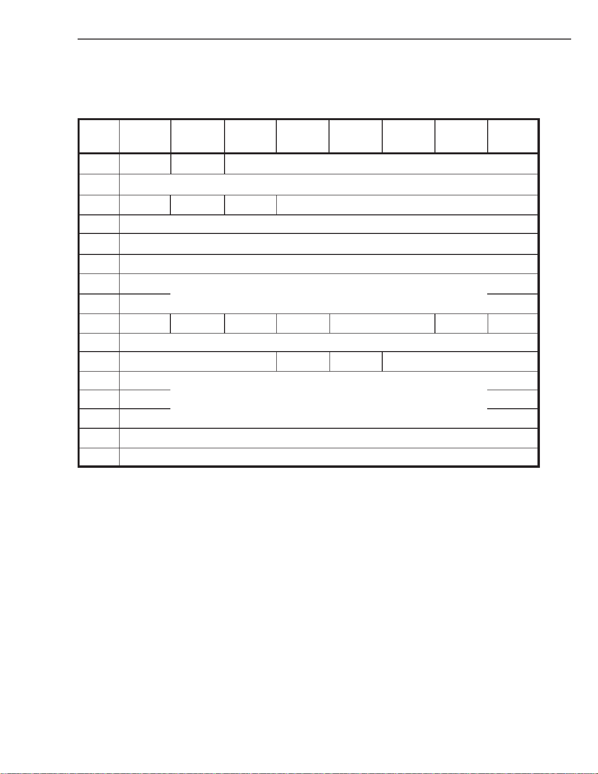
6. COMMAND SPECIFICATION
6. 07. 3 Device Configuration Page
The drive supports the Device Configuration Page which has the following format:
Bit76543210
Byte
0 PS (0) Reserved Page Code (10h)
1 Page Length (0Eh)
2 Reserved CAP CAF Active Format
3 Active Partition
4 Write Buffer Full Ratio (00h)
5 Read Buffer Empty Ratio (00h)
6 (MSB)
Write Delay Time
7 (LSB)
MODE SELECT
8 DBR (0) BIS (1) RSmk AVC (0) SOCF (00b) RBO (0) REW
9 Gap Size (00h)
10 EOD Defined (000b) EEG (1) SEW Reserved
11 (MSB)
12 Buffer Size at Early Warning (00 00 00h)
13 (LSB)
14 Select Data Compression Algorithm
15 Reserved
Table 6-30: Device Configuration Page
CAP:
The Change Active Partition bit, then set to one, indicates that the logical partition is changed to the one specified by
the Active Partition Field. This is a feature supported by the drive and is discussed below.
SONY SDT-10000/SDT-11000 DDS Tape Drive
6 - 43
Page 95

6. COMMAND SPECIFICATION
CAF:
The Change Active Format bit, set to one, indicates that the active format is to be changed to that set in the Active
Format Field.
Active Format:
The definition of this field is DAT specific. This field is used to enable DDS format options and is described below:
43210
Disable RAW ECC-3 N-Group
Disable RAW:
This bit is used to enable or disable the use of Read-After-Write error detection. If this bit is NOT set, RAW is
enabled. This is the drive’s default configuration.
ECC-3:
This bit is used to enable or disable the use of Third Level Error Correction (ECC-3). If this bit is set, ECC-3 is
enabled. This is the drive’s default configuration.
N-Group:
The value of this field indicates the number of times a group will repeatedly be written to tape. The default is zero
repetitions. This feature may be used to performance match the drive with the Host. A decode of the field is shown
below:
This field will not be used on DDS-3 and DDS-4.
MODE SELECT
Table 6-31: Active Format
2 1 0 Number of Repetitions
0 0 0 0 (Default)
001 1
010 2
011 3
100 4
101 5
110 6
111 7
Table 6-32: N-Group field values
Active Partition:
Indicates the current logical partition number in use on the medium.
The partition number may be either partition 0 or 1. Setting this field to any other values will be rejected by the drive
with a CHECK CONDITION status and the ILLEGAL REQUEST sense key set.
6 - 44
SONY SDT-10000/SDT-11000 DDS Tape Drive
Page 96

6. COMMAND SPECIFICATION
The drive will default to Partition 0 if the drive has been power-cycled, has received a BUS DEVICE RESET
message, a Hard RESET or a tape is loaded. This is irrespective of whether the tape has been partitioned or not.
If the media is to be used in the two partition format, the media must first be initialized using MODE SELECT
Medium Partitions Parameter Page.
If the currently loaded tape has not been formatted to be a two partition tape and the Host requests the Active
Partition to be changed via the CAP and Active Partition fields, then the drive will return a CHECK CONDITION
status with a MEDIUM ERROR sense key set.
Write Buffer Full Ratio and Read Buffer Empty Ratio:
These fields are not supported by the drive. Setting these fields to anything other than zero will cause the drive to
return a CHECK CONDITION status and an ILLEGAL REQUEST sense key.
The drive implements an algorithm which automatically adjusts these ratios so as to maximize streaming to the
Host.
Write Delay Time:
This field indicates the maximum time, in 100 millisecond increments, that the drive shall wait with a partially full
buffer before forcing the data to tape. The drive defaults to a 10 second delay since the last SCSI bus activity before
the data is flushed from the buffer to the tape. If Write Delay Time is set to zero the drive will wait indefinitely for
the data group to be filled.
DBR: This field is not supported and should be always set to 0.
BIS: Block Identifiers Supported is set to one to indicate that the media has recorded information about the logical
block ID relative to the partition.
The DBR and BIS bit are only valid on a MODE SENSE command where they are used to report drive capabilities. These bits are ignored by the drive on a MODE SELECT command. The drive will not return a CHECK
CONDITION.
RSmk:
The Report Set Mark bit, when set to one, indicates that Save Set Marks will be reported to the drive. When zero,
Save Set Marks are NOT reported. The default is one, Save Set Marks reported.
AVC:
Automatic Velocity Control function is not supported by the drive and if this bit is set a CHECK CONDITION
status is returned with an ILLEGAL REQUEST sense key.
SOCF:
Stop on Consecutive Filemarks function is not supported by the drive and if this bit is set a CHECK CONDITION
status is returned with an ILLEGAL REQUEST sense key.
RBO:
This field is not supported. If this bit is set a CHECK CONDITION status is returned with an ILLEGAL REQUEST
sense key.
REW:
The drive returns Report Early-Warning End-of-Media bit not set. This indicates that the drive will not report the
early-warning condition on reads but will report early-warning on writes at a distance of 1500 mm (:DDS2/3 , 500
mm: DDS-1) before the physical End-Of-Partition
Gap Size:
This field is not used by the DDS format and shall be set to zero otherwise a CHECK CONDITION with an
ILLEGAL REQUEST sense key will be returned.
EOD Defined:
This field shall always be set to zero so that the drive will use its default EOD definition to detect and generate EOD.
Any other value will cause the drive to return a CHECK CONDITION status with an ILLEGAL REQUEST sense
key set.
MODE SELECT
SONY SDT-10000/SDT-11000 DDS Tape Drive
6 - 45
Page 97

6. COMMAND SPECIFICATION
EEG:
The Enable EOD Generation bit shall always be set to indicate that drive will generate an EOD. The drive generates
an EOD mark prior to any change of direction, if that change follows a write-type operation. This bit is only valid
on the MODE SENSE command where it is used to report drive capabilities. This bit is ignored by the drive on a
MODE SELECT command. The drive will not return a CHECK CONDITION.
SEW:
The Synchronize at Early-Warning bit is always set to ONE indicates buffered write data. File-marks and Set-marks
at or after Early-Warning End-of-Media will be written to the Medium. The SEW bit changeable. A value of ZERO
indicates that the target will retain any unwritten buffered data. File-marks, or Set-marks in the buffer when logical
Early-Warning is encountered. The default is 0.
Buffer Size at Early Warning:
This field is not supported by the drive and if set a CHECK CONDITION status is returned with an ILLEGAL
REQUEST sense key set.
Select Data Compression Algorithm:
The SDT-10000/SDT-11000 supports the Data Compression Page and that page should be used instead of this field
to control Data Compression. This field is not supported by the drive and if set a CHECK CONDITION status is
returned with an ILLEGAL REQUEST sense key set.
MODE SELECT
6 - 46
SONY SDT-10000/SDT-11000 DDS Tape Drive
Page 98
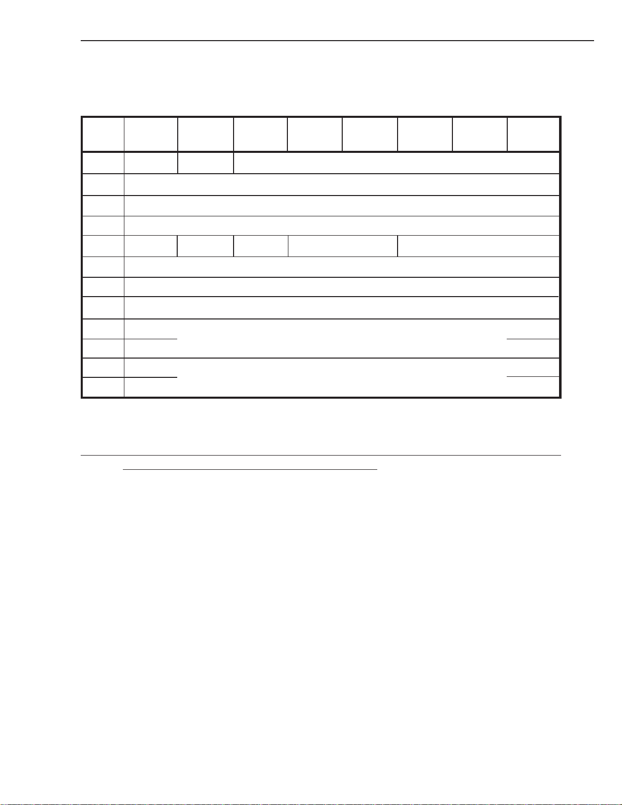
6. COMMAND SPECIFICATION
6. 07. 4 Medium Partitions Parameter Page
The drive supports the Medium Partitions Parameter Page, which has the following format:
Bit76543210
Byte
0 PS (0) Reserved Page Code (11h)
1 Page Length (0Ah)
2 Maximum Additional Partitions (01h)
3 Additional Partitions Defined (00h or 01h)
4 FDP (0) SDP (0) IDP PSUM (10b) Reserved
5 Medium format Recognition (03h)
6 Reserved
7 Reserved
MODE SELECT
8 (MSB)
9 (LSB)
10 (MSB)
11 (LSB)
Partition Size (Partition 0)
Partition Size (Partition 1)
Table 6-33: Medium Partitions Parameter Page
Warning: This page is used to format a tape to one or two partitions. Extreme care must be used with this
parameter page to avoid accidental reformatting of a tape.
Maximum Additional Partitions:
This field is only valid on MODE SENSE where it is used report the maximum number of additional partitions that
are supported by the drive, which is one.
Additional Partitions Defined:
This field specifies the number of additional partitions to be defined for the tape based on the IDP bit. The maximum allowed is the value returned in the Maximum Additional Partitions field, which for the drive is one. Therefore, the supported values are zero or one.
If the Mode Sense command is issued with the Parameter List Length set to 16h, the Page Length that is returned
will be 8 bytes, and the value for Partition 1 will be returned in bytes 8, 9. The value for Partition 0 is not returned
in this case.
For issuing Mode Select with Additional Partition Defined = 0, the command will function properly even when the
Parameter List Length of the CDB is set to 14h. In this case, it is necessary to set the Parameter Length to 6h.
SONY SDT-10000/SDT-11000 DDS Tape Drive
6 - 47
Page 99
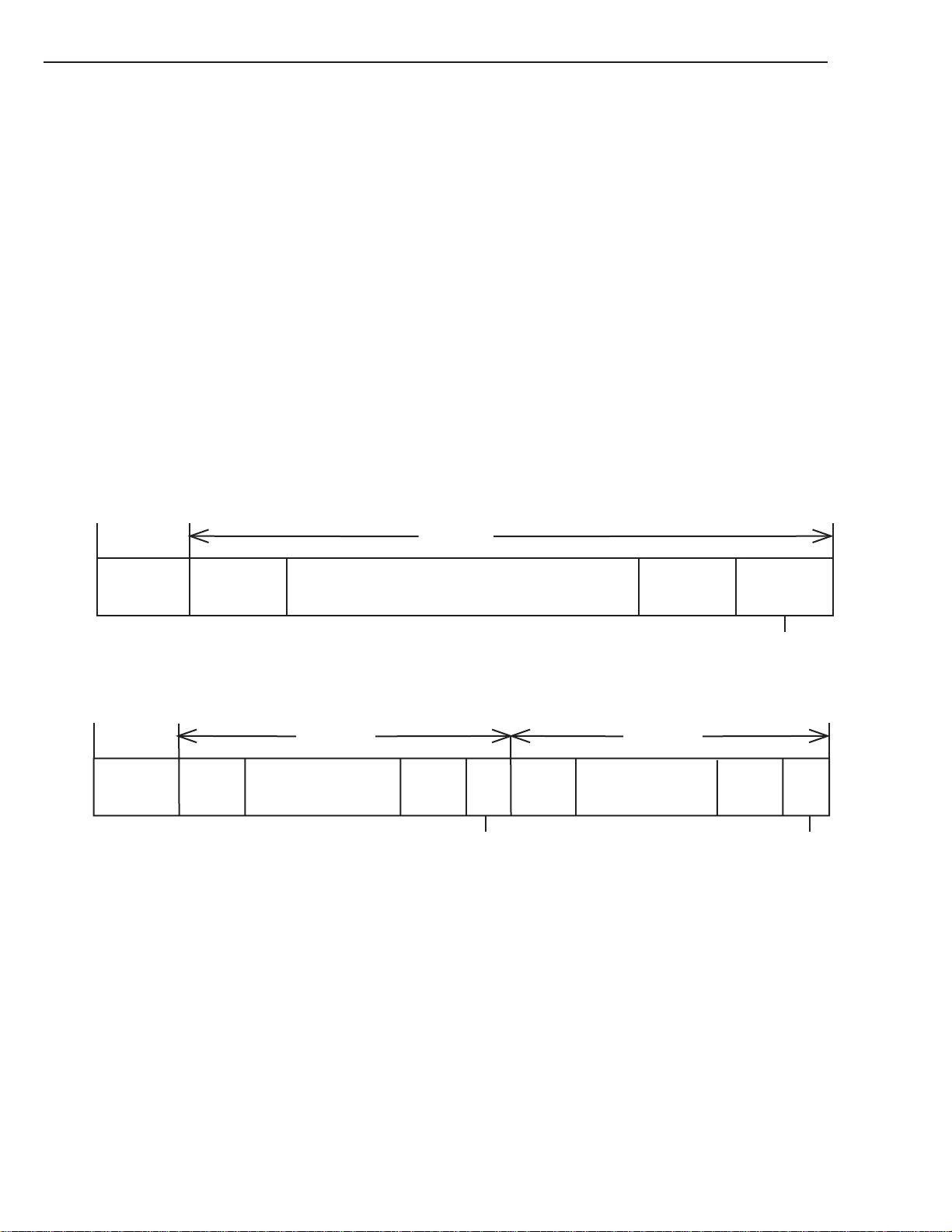
6. COMMAND SPECIFICATION
FDP:
The Fixed Data Partitions bit is not supported by the drive and if set, a CHECK CONDITION status is returned with
an ILLEGAL REQUEST Sense Key set.
SDP:
The Select Data Partitions bit is not supported by the drive and if set, a CHECK CONDITION status is returned with
an ILLEGAL REQUEST Sense Key set.
IDP:
The Initiator Defined Partitions bit is supported and, when set to one, indicates that the tape shall be partitioned
based on the Additional Partitions Defined field, PSUM and Partition Size field. Setting of this bit is only valid at
BOM, otherwise the drive will return a CHECK CONDITION status with an ILLEGAL REQUEST Sense Key set.
The DDS format allows the tape to be split into two entirely separate and independent partitions. Each partition will
have its own Reference, System and Vendor Group area. Each partition will have a minimum size of 2541 frames. The
maximum size of a partition will be the whole tape. The partitions may exist together or the entire tape may be treated
as a single partition. This is illustrated below:
MODE SELECT
Single Partition Tape
BOM BOT
Partition 0
Device Area System Area End of DataUser Data Area
Two Partition Tape
BOM BOT
Partition 1
Device Area
BOM = Beginning-of-Media (Physical)
BOT = Beginning-of-Tape (Logical)
EOM = End-of-Media (Physical)
EOP = End-of-Partition (Logical)
EOT = End-of-Tape (Logical)
System
Area
User Data Area
End of
Data
EOT
EOP/BOP
System
Area
Partition 0
User Data Area
EOP/EOM
EOT
EOP/EOM
End of
Data
EOT
6 - 48
Note: The System area consists of three sub-sections:
Reference Area
System Area
Vendor Group
Figure 6-1: Tape Partition Layout
SONY SDT-10000/SDT-11000 DDS Tape Drive
Page 100

6. COMMAND SPECIFICATION
The Host may, therefore, partition a tape into one partition which spans the whole physical length of the tape or into two
partitions, each of which will behave as completely separate and independent tapes.
A tape does not require partitioning prior to use. If a Host only wishes to use a single partition tape, then there is no need
to send this page. On the first WRITE to a blank tape, the device will create the System, Reference and Vendor areas on
tape before proceeding with the write. To reformat from a two to a single, or from a single to a two partition tape, the
Host is required to use the Medium Partitions Parameter page.
PSUM:
The Partition Size Unit of Measured field defines the units in which the Partition Size value selects the partition size,
which in the case of this drive is Megabytes. Therefore, the drive returns 10b for a MODE SENSE and will only
accept this value for a MODE SELECT, otherwise a CHECK CONDITION status is returned with an ILLEGAL
REQUEST Sense Key set.
Medium Format Recognition:
This field is only valid on a MODE SENSE and is set to 03h to indicate that the drive is capable of format and
partition recognition.
MODE SELECT
Partition Sizes:
This field allows the initiator to allocate the capacity of the second partition, Partition 1. It will also allow the
initiator to reallocate the capacity of previously partitioned tapes.
The Partition Size specifies the capacity of Partition 1 in Megabytes. The drive rounds the Partition Size to the next
whole group value and then applies an algorithm which allows for the writing of ECC-3 frames and for RAW error
recovery so as to reserve sufficient physical space on the media for the specified capacity.
If the Additional Partitions Defined and Partition Size fields are set to zero the drive will initialize the tape as Partition
0, spanning the whole length of the tape.
Partition 0 size is only valid during MODE SENSE and is ignored during MODE SELECT Remaining Capacity goes to
P.0.
SONY SDT-10000/SDT-11000 DDS Tape Drive
6 - 49
 Loading...