

1285-2552 Rev 8
© Sony Mobile Communications AB – Company Internal
Working Instructions
D6502, D6503, D6543, L50w
TM
- mechanical -
Xperia
Z2

© Sony Mobile Communications AB – Company Internal
2(80)
Working Instructions (mech)
CONTENTS
1 Exterior Views ................................................................................. 4
1.1 D6502, D6503, D6543 & L50w .............................................................. 4
2 Tools ................................................................................................ 5
3 Disassembly.................................................................................... 6
3.1 SIM Tray ................................................................................................ 6
3.2 Back Panel ............................................................................................ 6
3.3 Adhesive Battery .................................................................................. 7
3.4 Sheet FPC Battery & Battery ............................................................... 8
3.5 Antenna WLAN ..................................................................................... 9
3.6 Main Camera ......................................................................................... 9
3.7 Sheet CU 17 x 4 .................................................................................. 10
3.8 Front assy & Main PBA ...................................................................... 10
4 Replacement ................................................................................. 12
4.1 SIM Tray .............................................................................................. 12
4.2 Back Panel & Adhesive Panel Back .................................................. 12
4.3 Adhesive Battery ................................................................................ 12
4.4 Sheet FPC Battery .............................................................................. 12
4.5 Battery ................................................................................................. 13
4.6 Antenna WLAN ................................................................................... 13
4.7 Main Camera ....................................................................................... 13
4.8 Sheet CU 17 x 4 .................................................................................. 13
4.9 Display Frame ..................................................................................... 14
4.10 Adhesive MIC Con .............................................................................. 15
4.11 Cable RF Coax .................................................................................... 17
4.12 Camera Chat ....................................................................................... 19
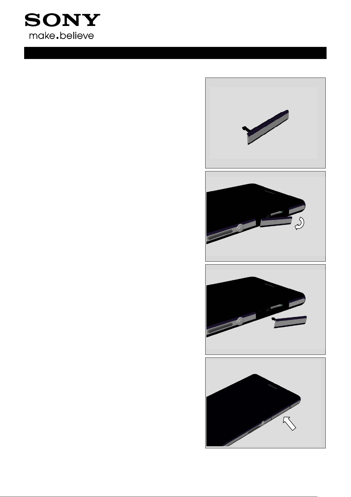
4.13 Cap SD ................................................................................................ 20
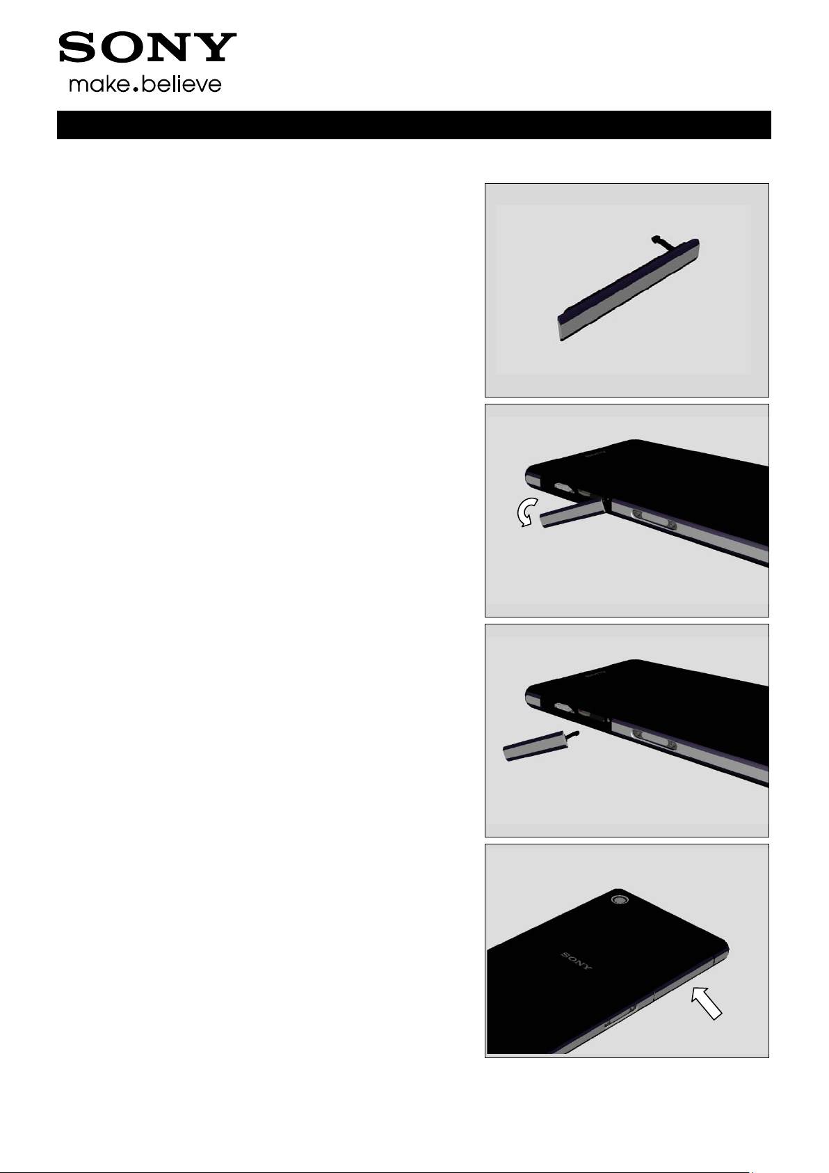
4.14 Cap USB .............................................................................................. 21
4.15 Core Unit Label ................................................................................... 22
4.16 Cushion Relay FPC ............................................................................ 23
4.17 Earspeaker (Top Speaker) & Adhesive Earspeaker ......................... 24
4.18 FPC Audio Jack & Adhesive Audio Jack .......................................... 26
4.19 FPC CG ............................................................................................... 30
4.20 FPC Relay & Adhesive CU 25 x 6 - 3 pcs & Sheet CU 46 x 5 & Sheet
CU 18 x 5 ............................................................................................. 32
4.21 Holder 2nd Mic ................................................................................... 38
4.22 Holder Camera Chat ........................................................................... 39
4.23 Holder Loudspeaker & Adhesive Lo udspe a k e r Lid & Adh Speaker
Back & Adh VIB Conn & Adh with mesh 14 x 5................................ 40
4.24 PBA An t e n n a ...................................................................................... 49
1285-2552 Rev 8

© Sony Mobile Communications AB – Company Internal
3(80)
Working Instructions (mech)
4.25 Plate Speaker ...................................................................................... 50
4.26 Ring Audio Jack ................................................................................. 52
4.27 Sheet Battery Adhesive Top .............................................................. 53
4.28 Sheet LCD 18 x 7 ................................................................................ 54
4.29 Sheet LCD 7 x 7 .................................................................................. 54
4.30 Sheet Thermal Conductive ................................................................ 55
4.31 Shield Camera .................................................................................... 56
4.32 Spacer 10 x 4 ...................................................................................... 57
4.33 Tray Core Unit Label .......................................................................... 58
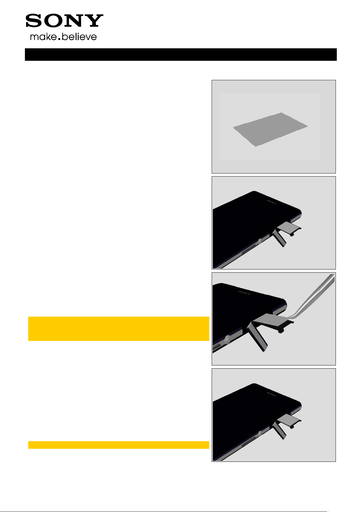
4.34 Water indicator I ................................................................................. 59
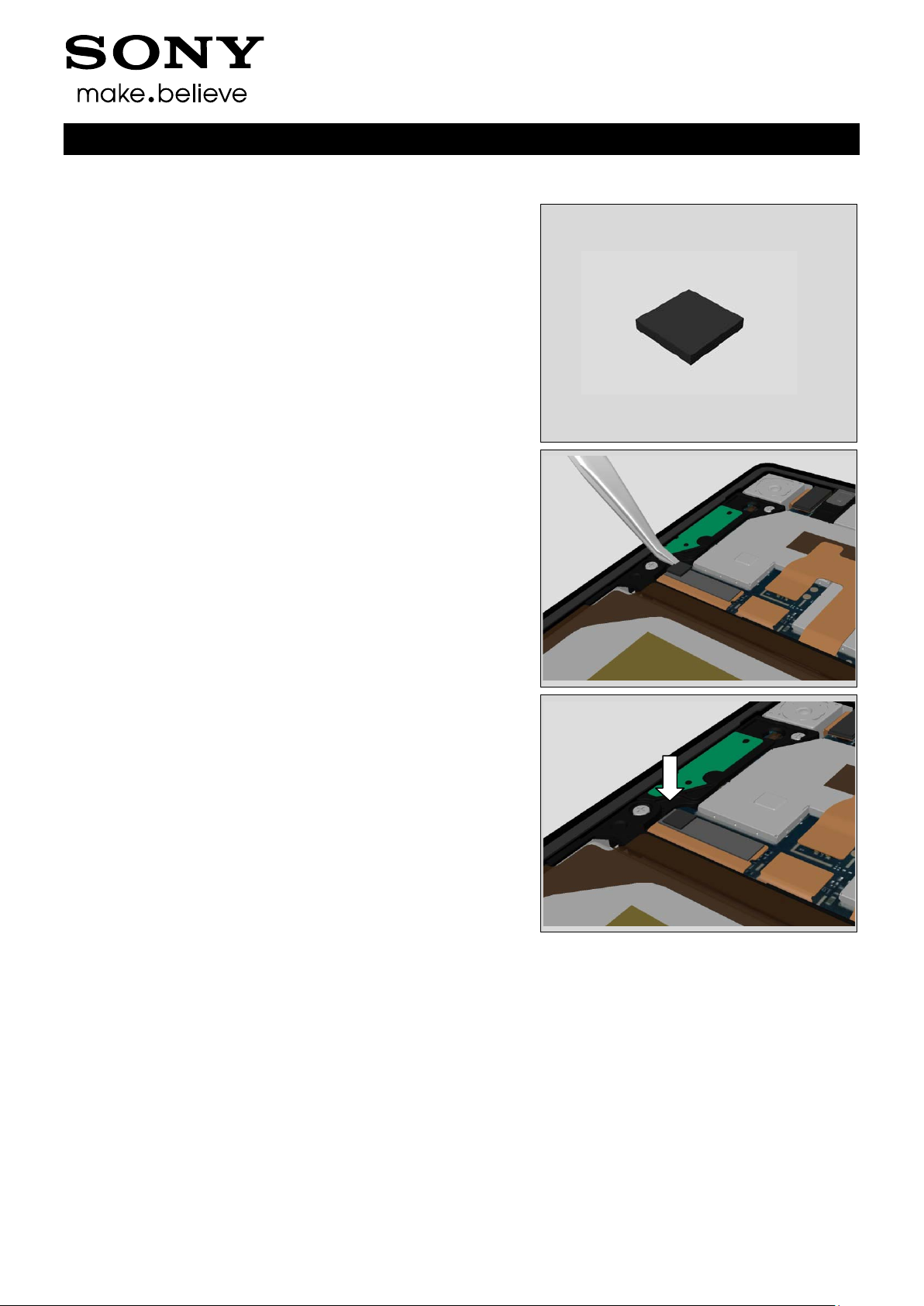
4.35 Water indica t or II ................................................................................ 60
4.36 Vibrator & Adhesive VIB & Spacer 5 x 2.5 ........................................ 61
4.37 Cushion Cam ...................................................................................... 63
4.38 Sheet Guide Label .............................................................................. 64
4.39 Sheet 5x10 .......................................................................................... 65
4.40 Spacer 8x5 .......................................................................................... 66
4.41 Sheet 1st MIC ...................................................................................... 67
4.42 Board Swap - Replacement ............................................................... 68
4.43 Board Swap – Change Label ............................................................. 69
4.44 Board Swap – Customize of Software .............................................. 69
5 Reassembly................................................................................... 70
5.1 Front assy & Main PBA ...................................................................... 70
5.2 Sheet CU 17 x 4 .................................................................................. 71
5.3 Main Camera ....................................................................................... 72
5.4 Antenna WLAN ................................................................................... 72
5.5 Battery & Sheet FPC Battery ............................................................. 73
5.6 Adhesive Battery ................................................................................ 75
5.7 Back Panel with Adhesive Panel Back ............................................. 75
5.8 SIM Tray .............................................................................................. 79
6 Revision History ........................................................................... 80
For general information about mechanical repair related issues, refer to
1220-1333: Generic Repair Manual - mechanical
1285-2552 Rev 8
© Sony Mobile Communications AB – Company Internal
4(80)
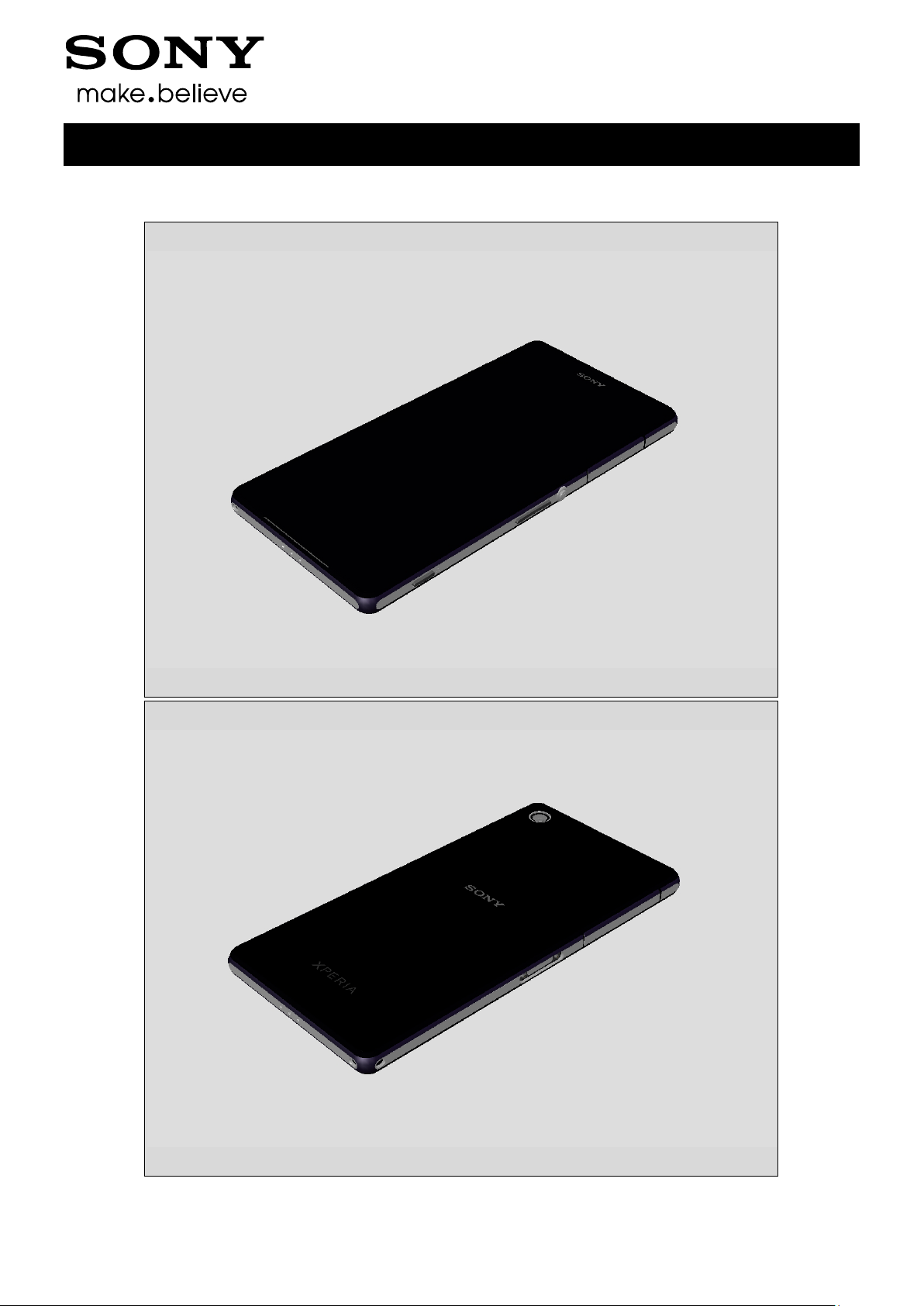
1 Exterior Views
1.1 D6502, D6503, D6543 & L50w
Working Instructions (mech)
1285-2552 Rev 8
© Sony Mobile Communications AB – Company Internal
5(80)
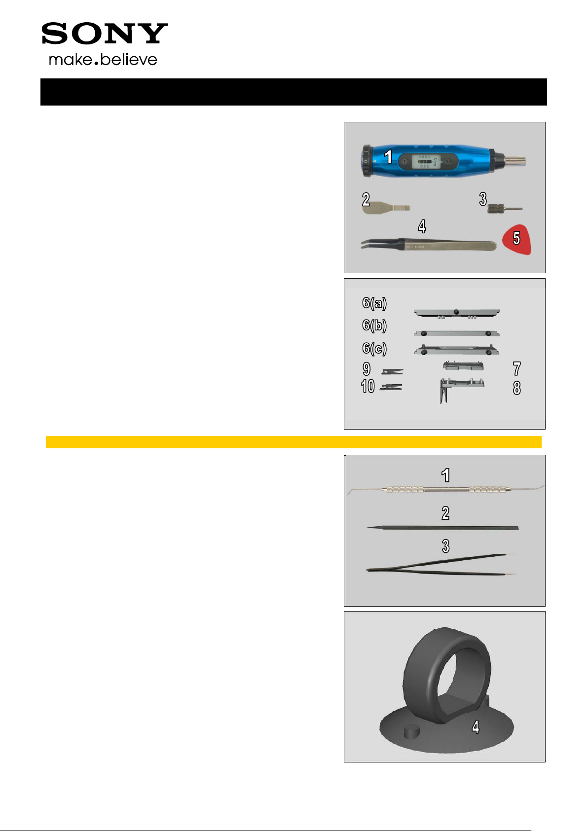
2 Tools
SPECIAL TOOLS
1. Torque Screwdriver
2. Front Opening Tool
3. Bits (JCIS No 0)
4. Flex Film Assembly Tool
5. Guitar Pick
6a & c. Top and Bottom Press
6b. Top press inlay no 2
7. Rear Panel Adhesive Align Fixture
8. Audio Jack Press
9. Earspeaker/Loudspeaker Top
10. Speaker Holder Press
Working Instructions (mech)
For part no’s on the tools above, refer to the ‘Tools Catalogue/Matrix’.
ST ANDARD TOOLS
1. Dentist Hook
2. Nylon Pointer
3. Tweezers
4. Suction Cup
1285-2552 Rev 8
© Sony Mobile Communications AB – Company Internal
6(80)
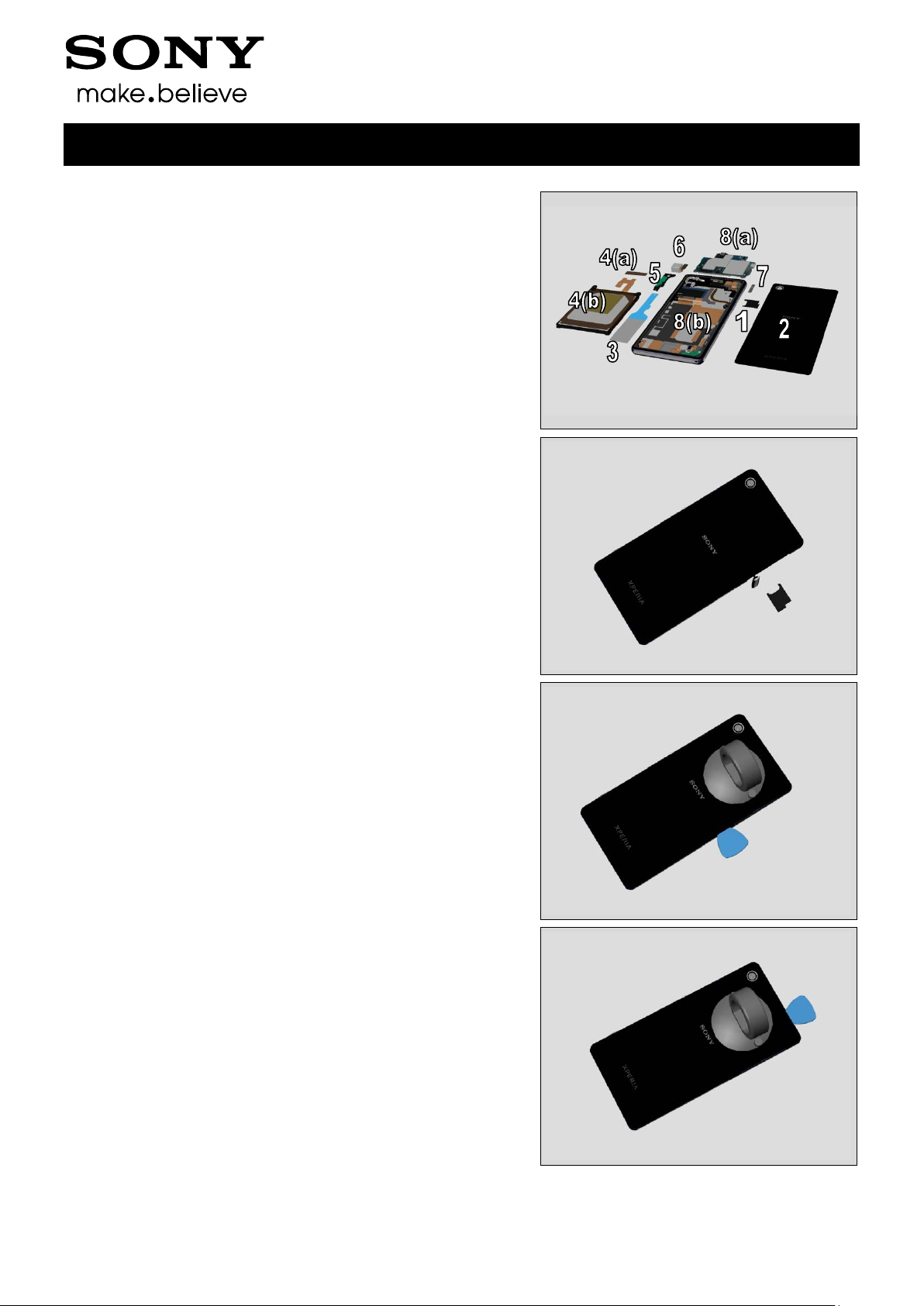
3 Disassembly
The disassembly is done in the following order:
1. SIM Tray
2. Back Panel
3. Adhesive Battery
4. Sheet FPC Batter y ( a) & Battery (b)
5. Antenna WLAN
6. Main Camera
7. Sheet CU 17 x 4
8. Front assy (a) & Main PBA (b)
3.1 SIM Tray
Open the Cap USB and remove the SIM card and the
SIM Tray.
Working Instructions (mech)
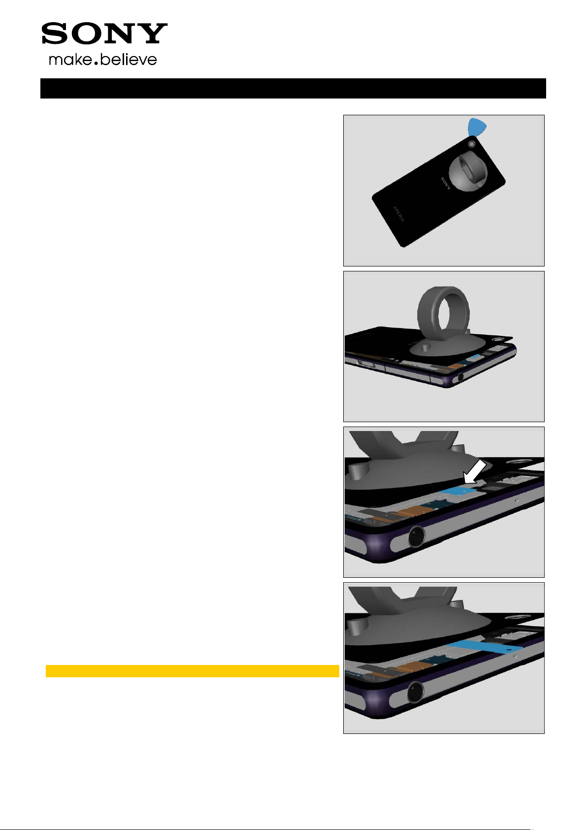
3.2 Back Panel
Attach the Suction cup, insert the Guitar Pick.
Slide along all sides.
1285-2552 Rev 8
© Sony Mobile Communications AB – Company Internal
7(80)
Disassembly
Be careful not to damage the camera.
Lift up the upper part of the Back Panel slightly.
Working Instructions (mech)
3.3 Adhesive Battery
Capture the Adhesive Battery tab.
Pull the tab slowly in a horizontal direction
until you removed the adhesive completely.
Scrap! Not to be reused.
1285-2552 Rev 8
© Sony Mobile Communications AB – Company Internal
8(80)
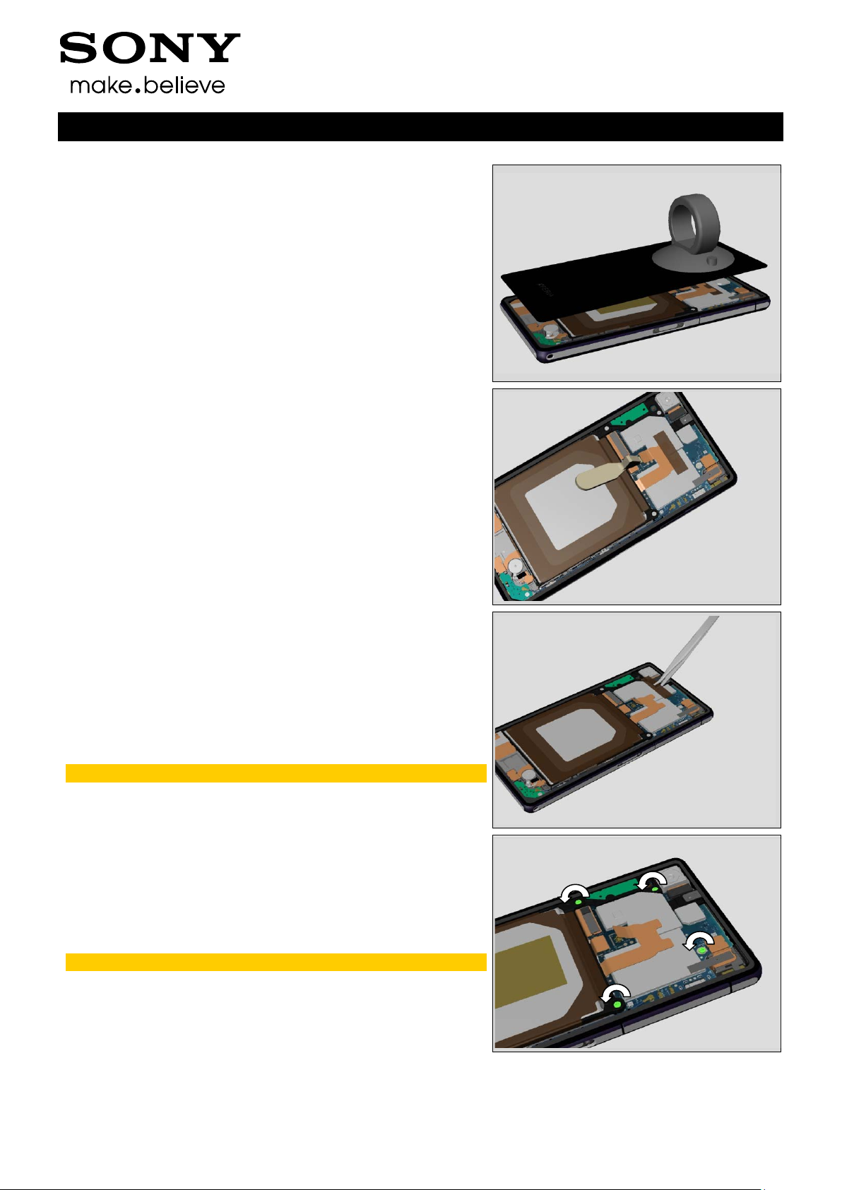
Disassembly
Remove the back Panel.
Unsnap the BtB connector of the Battery.
Working Instructions (mech)
3.4 Sheet FPC Battery & Battery
Remove the Sheet FPC Battery.
Scrap! Not to be reused.
Remove the four Screws by using a screwdriver with
Bits (JCI S No 0).
Scrap! Not to be reused.
1285-2552 Rev 8
© Sony Mobile Communications AB – Company Internal
9(80)
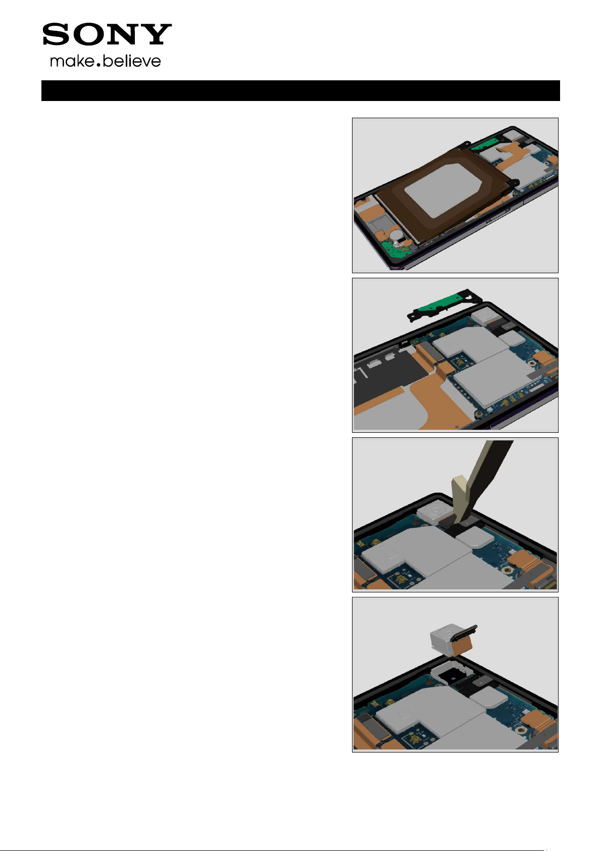
Disassembly
Lift up the Battery in an angel and remove the Battery.
3.5 Antenna WLAN
Remove the Antenna WLAN.
Working Instructions (mech)
3.6 Main Camera
Unsnap the BtB connector of the Camera.
Remove the Camera. Be careful not to damage it.
1285-2552 Rev 8
© Sony Mobile Communications AB – Company Internal
10(80)
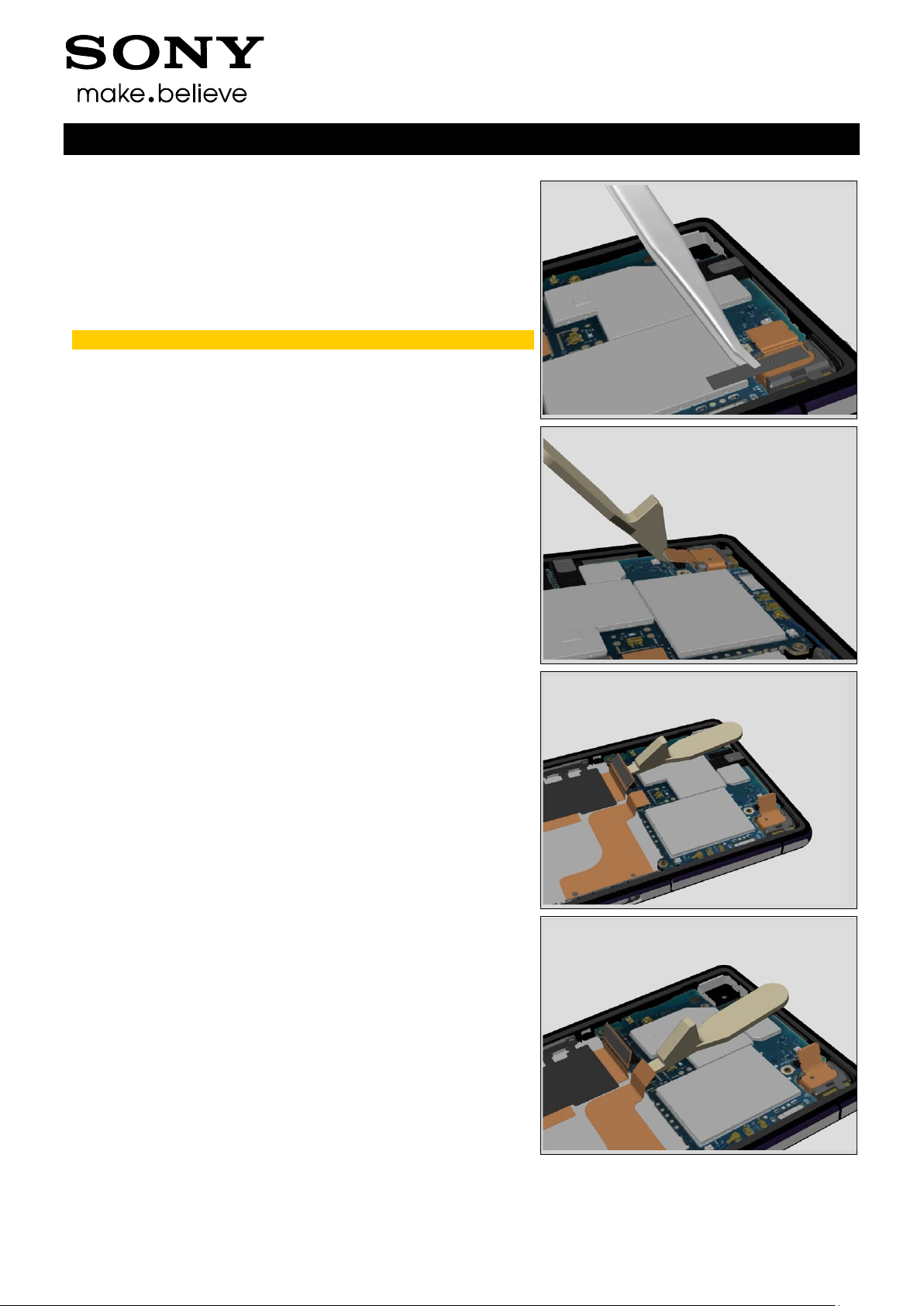
Disassembly
3.7 Sheet CU 17 x 4
Remove the Sheet CU 17 x 4.
Scrap! Not to be reused.
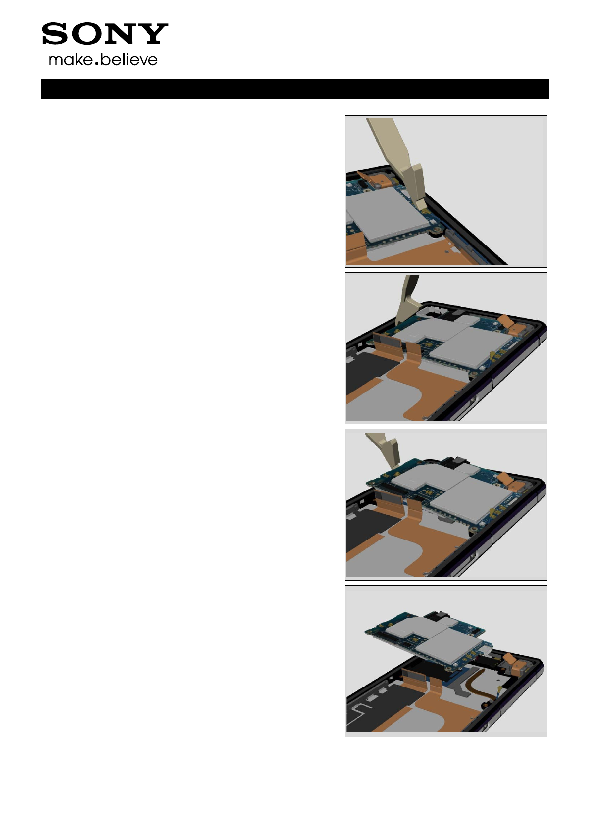
3.8 Front assy & Main PBA
Unsnap the BtB connector of FPC Audio Jack.
Working Instructions (mech)
Unsnap the BtB connector of FPC Relay.
Unsnap the BtB connector of FPC CG.
1285-2552 Rev 8
© Sony Mobile Communications AB – Company Internal
11(80)
Disassembly
Unsnap the connector of Cable RF Coax.
Insert the Front Opening Tool to release the Main PBA.
Working Instructions (mech)
Lift the main PBA.
Separate the Main PBA from the Front assy.
1285-2552 Rev 8
© Sony Mobile Communications AB – Company Internal
12(80)
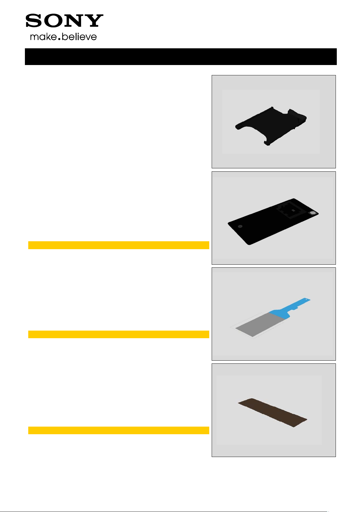
4 Replacement
4.1 SIM Tray
Follow the 3.1 Disassembly instructions!
Prepare the new SIM Tray .
Follow the 5.8 Reassembly instructions!
4.2 Back Panel & Adhesive Panel Back
Follow the 3.1 – 3.2 Disassembly instructions!
Prepare the new Back Panel with Adhesive Panel Back.
Follow the 5.7 – 5.8 Reassembly instructions!
Scrap! Do not reuse the Adhesive Panel Back.
Working Instructions (mech)
4.3 Adhesive Battery
Follow the 3.1 – 3.3 Disassembly instructions!
Prepare the new Adhesive Battery.
Follow the 5.6 – 5.8 Reassembly instructions!
Scrap! Do not reuse the Adhesive Battery.
4.4 Sheet FPC Battery
Follow the 3.1 – 3.4 Disassembly instructions!
Prepare the new Sheet FPC Battery.
Follow the 5.5 – 5.8 Reassembly instructions!
Scrap! Do not reuse the Sheet FPC Battery.
1285-2552 Rev 8
© Sony Mobile Communications AB – Company Internal
13(80)
Replacement
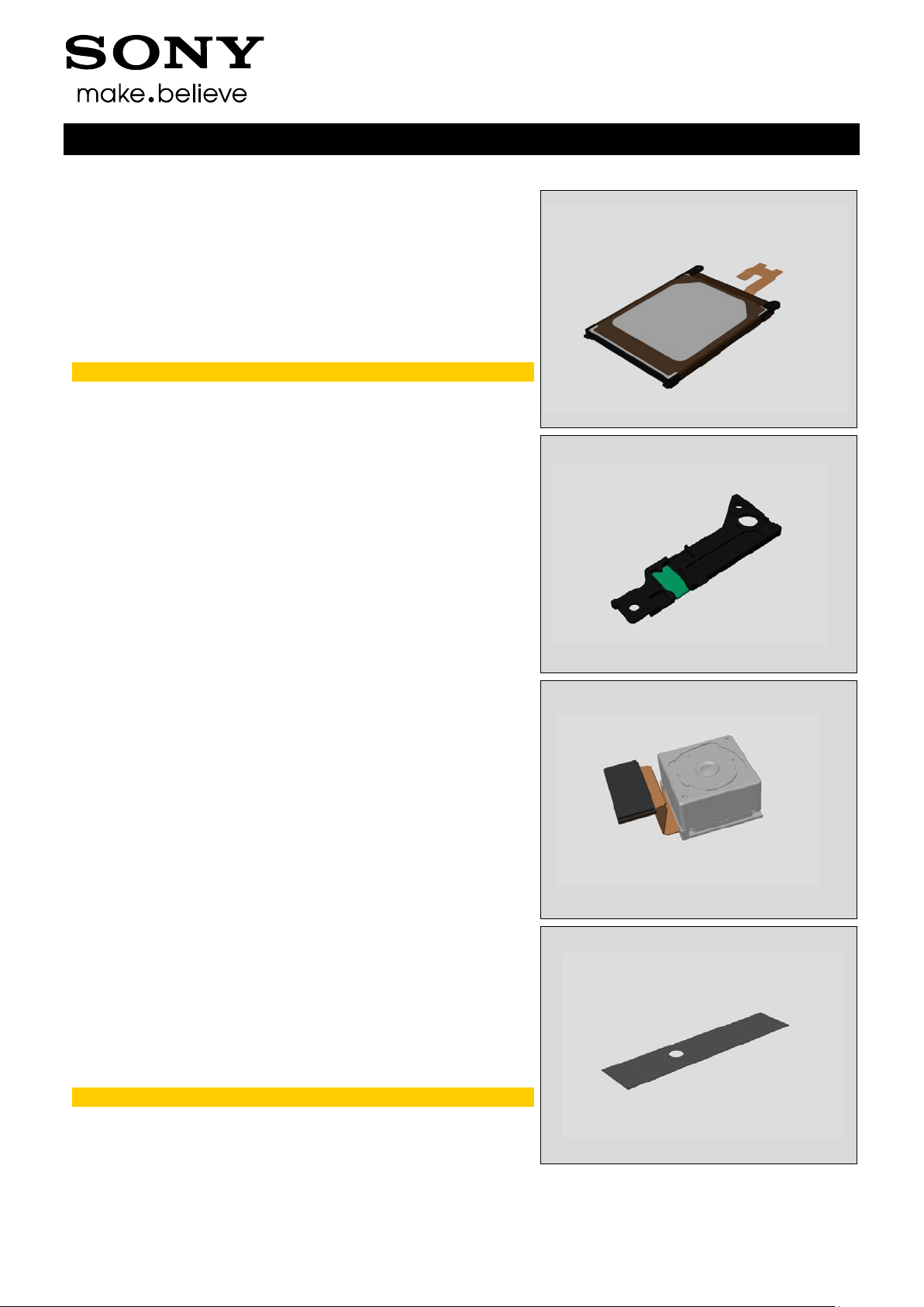
4.5 Battery
Follow the 3.1 – 3.4 Disassembly instructions!
Prepare the new Sheet FPC Battery.
Follow the 4.27 Replacement instructions.
Follow the 5.5 – 5.8 Reassembly instructions!
Visual Inspection of the Battery.
4.6 Antenna WLAN
Follow the 3.1 – 3.5 Disassembly instructions!
Prepare the new Antenna WLAN.
Follow the 5.4 – 5.8 Reassembly instructions!
Working Instructions (mech)
4.7 Main Camera
Follow the 3.1 – 3.6 Disassembly instructions!
Prepare the new Main Camera.
Follow the 5.3 – 5.8 Reassembly instructions!
4.8 Sheet CU 17 x 4
Follow the 3.1 – 3.7 Disassembly instructions!
Prepare the new Sheet CU 17 x 4.
Follow the 5.2 – 5.8 Reassembly instructions!
Scrap! Do not reuse the Sheet CU 17 x 4.
1285-2552 Rev 8
© Sony Mobile Communications AB – Company Internal
14(80)
Replacement
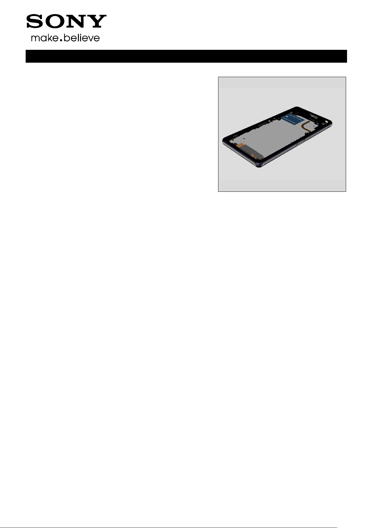
4.9 Display Frame
Follow the 3.1 – 3.8 Disassembly instructions!
Follow the 4.11, 4.19, 4.20, 4.23, 4.30, 4.37, 4.39, 4.40
Removal instructions!
Carry out the Removal as described below.
Prepare the new Display Frame .
Carry out the Installation as described below.
Follow the 4.39, 4.11, 4.19, 4.20, 4.23, 4.40, 4.30, 4.37
Installation instructions!
Follow the 5.1 – 5.8 Reassembly instructions!
Working Instructions (mech)
1285-2552 Rev 8
© Sony Mobile Communications AB – Company Internal
15(80)
Replacement
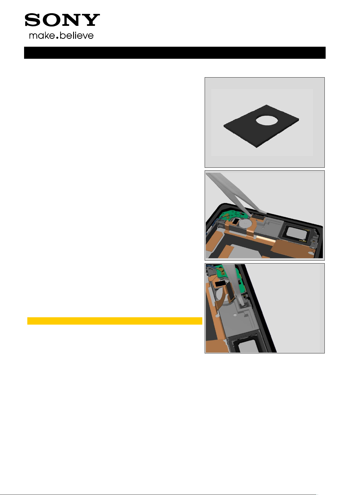
4.10 Adhesive MIC Con
Follow the 3.1 – 3.3 Disassembly instructions!
Carry out the Removal as described below.
Prepare the new Adhesive MIC Con.
Carry out the Installation as described below.
Follow the 5.6 – 5.8 Reassembly instructions!
REMOVAL
Lift the flex over the MIC with the Flex Film Assembly Tool.
Working Instructions (mech)
Remove the Adhesive MIC Con. Remove all remains of
the adhesive residue found on the Holder Loud speaker
and the MIC.
Scrap! Not to be reused!
1285-2552 Rev 8
© Sony Mobile Communications AB – Company Internal
16(80)
Replacement:
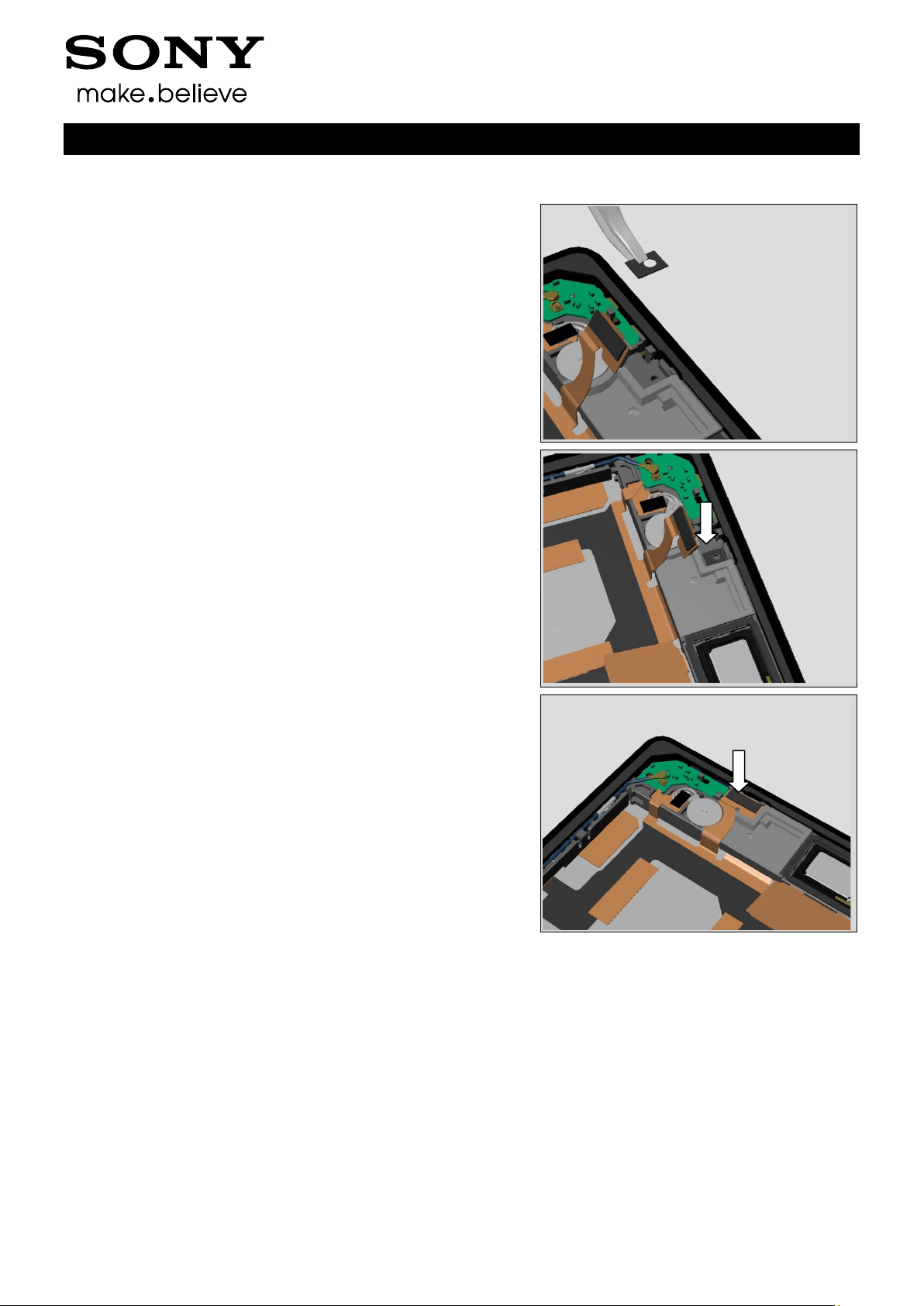
INSTALLATION
Place a new Adhesive MIC Con in the correct position.
Working Instructions (mech)
Press gently.
Attach the flex and press to secure its attachment.
1285-2552 Rev 8
© Sony Mobile Communications AB – Company Internal
17(80)
Replacement
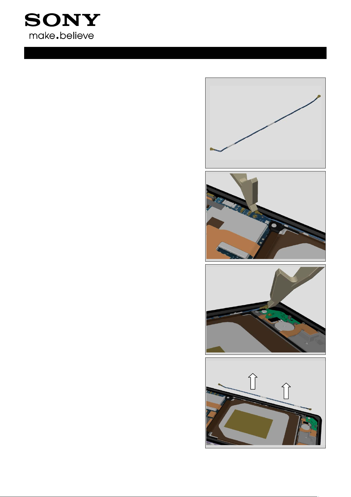
4.11 Cable RF Coax
Follow the 3.1 – 3.3 Disassembly instructions!
Carry out the Removal as described below.
Prepare the new Cable RF Coax.
Carry out the Installation as described below.
Follow the 5.6 – 5.8 Reassembly instructions!
REMOVAL
Disconnect the Cable RF Coax from the Main PBA.
Working Instructions (mech)
Disconnect the Cable RF Coax from the PBA Antenna.
Unsnap and remove the Cable RF Coax.
1285-2552 Rev 8
© Sony Mobile Communications AB – Company Internal
18(80)
Replacement:
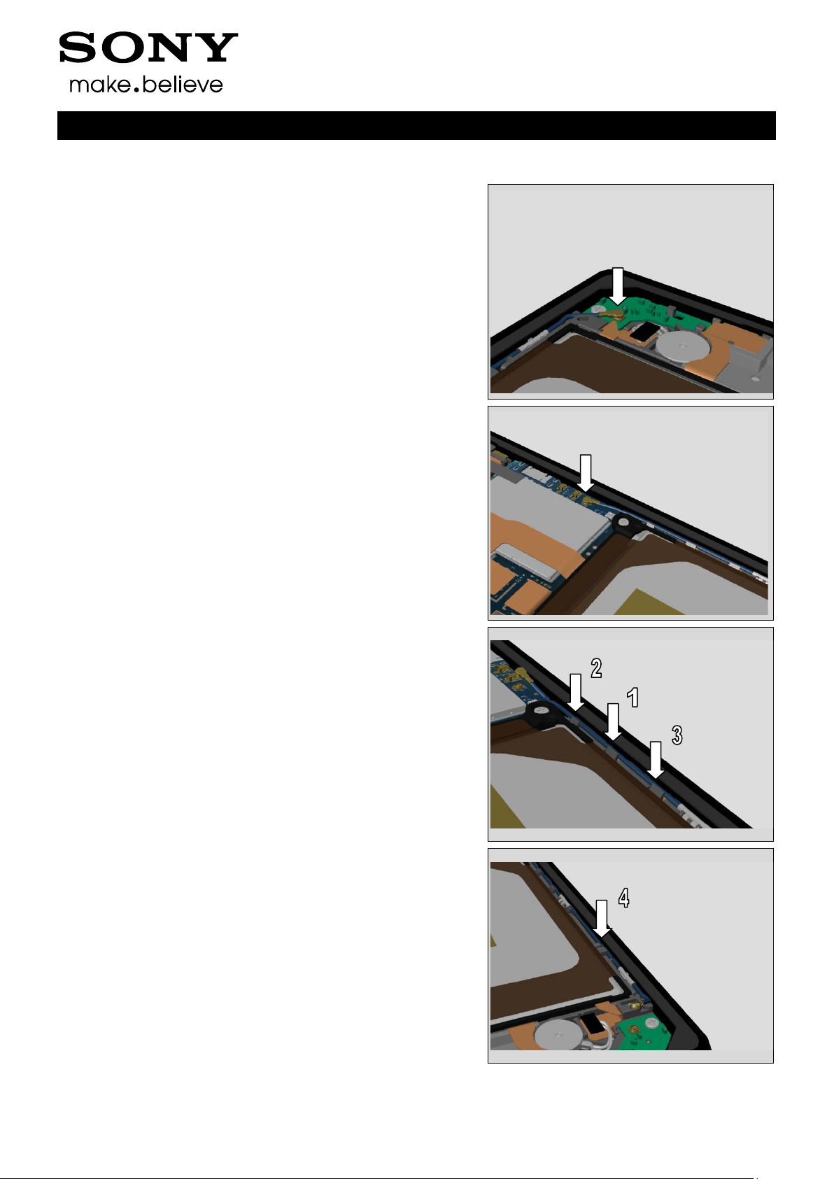
INSTALLATION
Connect the Cable RF Coax to the PBA Antenna.
Working Instructions (mech)
Connect the Cable RF Coax to the Main PBA.
Insert the Cable to the four hooks Nylon Pointer.
Visual check that the Cable is well fixed to the hooks.
No parts of the Cable should be higher than the inner
frame of the Display Frame.
1285-2552 Rev 8

© Sony Mobile Communications AB – Company Internal
19(80)
Replacement
4.12 Camera Chat
Follow the 3.1 – 3.8 Disassembly instructions!
Follow the 4.22 Removal instructions!
Carry out the Removal as described below.
Prepare the new Camera Chat.
Carry out the Installation as described below.
Follow the 4.22 Installation instructions!
Follow the 5.1 – 5.8 Reassembly instructions!
REMOVAL
Open the connector and remove the Camera Chat.
Working Instructions (mech)
INSTALLATION
Insert the Camera flex into the ZIF connector. Align the
two wings on the flex. Close the connector with your finger.
Push the Camera forward and down to secure the position
in the shield fence. Do not touch the lens.
1285-2552 Rev 8
© Sony Mobile Communications AB – Company Internal
20(80)
Replacement
4.13 Cap SD
Carry out the Removal as described below.
Prepare the new Cap SD.
Carry out the Installation as described below.
REMOVAL
Turn the Cap SD and pull.
The head of the plug is oval.
Working Instructions (mech)
INSTALLATION
Place a new Cap SD in the correct position.
Press to secure its position.
1285-2552 Rev 8
© Sony Mobile Communications AB – Company Internal
21(80)
Replacement
4.14 Cap USB
Carry out the Removal as described below.
Prepare the new Cap USB.
Carry out the Installation as described below.
REMOVAL
Turn the Cap USB and pull.
The head of the plug is oval.
Working Instructions (mech)
INSTALLATION
Place a new Cap USB in the correct position.
Press to secure its position.
1285-2552 Rev 8
© Sony Mobile Communications AB – Company Internal
22(80)
Replacement
4.15 Core Unit Label
Carry out the Removal as described below.
Prepare the new Core Unit Label.
Carry out the Installation as described below.
REMOVAL
Read the old Core Unit Label and write the information
into the ‘’LabelPrint Solution’ program.
Working Instructions (mech)
Open the Cap SD and pull out the Label Tray.
Remove the Core Unit Label.
Scrap Core Unit Label, not to be reused.
Remove and clean any remaining adhesive residue found
on Label Tray.
INSTALLATION
Check that the proper label format is loaded in the Zebra
printer and write a new Label by using the ‘Label Print’
software.
Place and align a new Core Unit Label in the correct
position. Press with a finger to secure the attachment.
One label only is allowed.
1285-2552 Rev 8
© Sony Mobile Communications AB – Company Internal
23(80)
Replacement
4.16 Cushion Relay FPC
Follow the 3.1 – 3.3 Disassembly instructions!
Carry out the Removal as described below.
Prepare the new Cushion Relay FPC.
Carry out the Installation as described below.
Follow the 5.6 – 5.8 Reassembly instructions!
REMOVAL
Remove the Cushion Relay FPC.
Working Instructions (mech)
INSTALLATION
Align by the top left corner of the Spacer on the BtB
connector. Press gently with your finger to secure the
attachment.
1285-2552 Rev 8

© Sony Mobile Communications AB – Company Internal
24(80)
Working Instructions (mech)
Replacement
4.17 Earspeaker (Top Speaker) & Adhesive Earspeaker
Follow the 3.1 – 3.8 Dis asse mbly instructions!
Carry out the Removal as described below.
Prepare the new Earspeaker with Adhesive.
Carry out the Installation as described below.
Follow the 5.1 – 5.8 Reassembly instructions!
REMOVAL
Remove the old Earspeaker.
Scrap! Not to be reused!
Remove the old Adhesive and all remains of the Adhesive
residue found in the cavity.
INSTALLATION
Clean the Earspeaker carefully before the new Adhesive
Earspeaker is attached to secure the water resistant.
Align a new Adhesive Earspeaker on the Earspeaker
without any wrinkles.
1285-2552 Rev 8

© Sony Mobile Communications AB – Company Internal
25(80)
Replacement:
Press to secure its attachment of the Adhesive.
Working Instructions (mech)
Clean the cavity carefully with alcohol before the new
Earspeaker is mounted. This action is done to secure the
water resistant of the unit.
Place the new Earspeaker in a proper position as shown
in the picture.
Press for 5 seconds with the Earspeaker/Loudspeaker Top
to secure the attachment.
Do not touch the pins of the Earspeaker!
1285-2552 Rev 8

© Sony Mobile Communications AB – Company Internal
26(80)
Working Instructions (mech)
Replacement
4.18 FPC Audio Jack & Adhesive Audio Jack
Follow the 3.1 – 3.8 Disassembly instructions!
Carry out the Removal as described below.
Prepare the new FPC Audio Jack with Adhesive.
Carry out the Installation as described below.
Follow the 5.1 – 5.8 Reassembly instructions!
REMOVAL
Remove the FPC Audio Jack gently.
Remove the old Adhesive and all remains of the Adhesive
residue found in the cavity.
INSTALLATION
Clean the cavity carefully with alcohol (twice) before the
new Adhesive Audio Jack is mounted. This action is done
to secure the water resistant of the unit.
1285-2552 Rev 8

© Sony Mobile Communications AB – Company Internal
27(80)
Replacement:
Align the Adhesive Audio Jack without any wrinkles.
Working Instructions (mech)
Prepare a new FPC Audio Jack.
Place the FPC Audio Jack and push gently forward ...
… to the correct position. Don’t reverse the movement to
avoid any malfunction of water resistant of the Adhesive.
1285-2552 Rev 8

© Sony Mobile Communications AB – Company Internal
28(80)
Replacement:
Use the Audio Jack Press …
Working Instructions (mech)
… to secure the attachment of the FPC Audio Jack.
Place the unit in the fixture.
Press for ten seconds with the Audio Jack Press to
secure the attachment.
1285-2552 Rev 8

© Sony Mobile Communications AB – Company Internal
29(80)
Replacement:
Turn over the rear part of the FPC Audio Jack.
Align and press gently with your finger to secure the
attachment.
Be careful with the BtB flex of the FPC Audio Jack, no
twist or pull of this section. Check that the FPC Audio
Jack isn’t damaged and properly fixed.
Working Instructions (mech)
1285-2552 Rev 8

© Sony Mobile Communications AB – Company Internal
30(80)
Replacement
4.19 FPC CG
Follow the 3.1 – 3.4 Disassembly instructions!
Carry out the Removal as described below.
Prepare the new FPC CG.
Carry out the Installation as described below.
Follow the 5.5 – 5.8 Reassembly instructions!
REMOVAL
Unsnap the BtB between FPC CG and Main PBA.
Working Instructions (mech)
Lift the flex to release the adhesive.
Rotate to release the three hooks.
Scrap! Not to be reused!
1285-2552 Rev 8

© Sony Mobile Communications AB – Company Internal
31(80)
Replacement:
INSTALLATION
Align and insert the left end of the rib. Push the right end
to fix the hooks.
Working Instructions (mech)
Align the flex. Secure the position and press to attach.
Check and confirm the guide holes.
Connect the BtB.
1285-2552 Rev 8

© Sony Mobile Communications AB – Company Internal
32(80)
Working Instructions (mech)
Replacement
4.20 FP C R elay & Adhesive CU 25 x 6 - 3 p cs & Sheet CU 46 x 5 & Sheet CU 18 x 5
Follow the 3.1 – 3.4 Disassembly instructions!
Follow the 4.39, 4.16, 4.23 Removal instructions!
Carry out the Removal as described below.
Prepare the new FPC Relay, Adhesives and Sheet.
Carry out the Installation as described below.
Follow the 4.16, 4.23, 4.39 Installation instructions!
Follow the 5.5 – 5.8 Reassembly instructions!
REMOVAL
Unsnap the BtB between the FPC Relay and the Main PBA.
Remove the Holder Loudspeaker according to 4.23
Remove the Sheet CU 18 x 5.
Remove the Sheet CU 46 x 5.
1285-2552 Rev 8

© Sony Mobile Communications AB – Company Internal
33(80)
Replacement:
Release the five hooks of the key holder.
Working Instructions (mech)
Rotate to release.
Release the holder on the opposite side.
Unsnap the BtB connector to the front.
Remove the FPC Relay.
1285-2552 Rev 8

© Sony Mobile Communications AB – Company Internal
34(80)
Replacement:
INSTALLATION
Remove the Adhesive CU 25 x 6 - 3 pcs and all remains
of the Adhesive residue on the metal plate.
Working Instructions (mech)
Align a new Adhesive CU 25 x 6 - 3 pcs.
Bend the separator 180 degrees by the bending line.
Let the separator be to later on.
Prepare a FPC Relay.
Do not reuse the FPC if it is damaged.
1285-2552 Rev 8

© Sony Mobile Communications AB – Company Internal
35(80)
Replacement:
Assemble the key holder with a rotation. Insert the holder
between the metal plate and the main cover.
Working Instructions (mech)
Secure the position of the five hooks.
Assembly the holder on the opposite side.
Start with the hook in the bottom ..
.. and press to lock the holder.
1285-2552 Rev 8

© Sony Mobile Communications AB – Company Internal
36(80)
Replacement:
Connect the BtB connector between the FPC Relay
and the front.
Working Instructions (mech)
Remove the separator and press to secure the attachment.
Align and assemble the Sheet CU 46 x 5.
Press with your finger to secure the attachment.
Align and assemble the Sheet CU 18 x 5.
Press with your finger to secure the attachment.
1285-2552 Rev 8

© Sony Mobile Communications AB – Company Internal
37(80)
Replacement:
Secure that the FPC Relay is properly attached..
Connect the BtB between the FPC Relay and the Main PBA.
Replace the Holder Loudspeaker according to 4.23
Assemble a new Cushion Relay FPC 4.16
Working Instructions (mech)
1285-2552 Rev 8

© Sony Mobile Communications AB – Company Internal
38(80)
Replacement
4.21 Holder 2nd Mic
Follow the 3.1 – 3.3 Disassembly instructions!
Carry out the Removal as described below.
Prepare the new Holder 2nd Mic.
Carry out the Installation as described below.
Follow the 5.6 – 5.8 Reassembly instructions!
REMOVAL
Remove the Holder 2nd Mic gently.
Working Instructions (mech)
Do not touch the acoustic cabinet (mark in blue).
INSTALLATION
Align and insert the hook. Place the Holder 2nd Mic in
an angel.
Do not touch the acoustic cabinet!
Press (not at the acoustic cabinet) to secure its attachment.
Check that the Holder is well fixed.
No gap (by the blue line in the picture), the guiding
boss shouldn’t be visible!
1285-2552 Rev 8

© Sony Mobile Communications AB – Company Internal
39(80)
Replacement
4.22 Holder Camera Chat
Follow the 3.1 – 3.8 Disassembly instructions!
Carry out the Removal as described below.
Prepare the new Holder Camera Chat.
Carry out the Installation as described below.
Follow the 5.1 – 5.8 Reassembly instructions!
REMOVAL
Remove the Holder Camera Chat.
Working Instructions (mech)
INSTALLATION
Mount a new Holder Camera Chat.
1285-2552 Rev 8

© Sony Mobile Communications AB – Company Internal
40(80)
Working Instructions (mech)
Replacement
4.23 Holder Loudspeaker & Adhesive Loudspeaker Lid & Adh Speaker Back & Adh VIB Conn & Adh with mesh 14 x 5
Follow the 3.1 – 3.4 Disassembly instructions!
Follow the 4.40 and 4.25 Removal instructions!
Carry out the Removal as described below.
Prepare the new Holder Loudspeaker & Adhesives.
Carry out the Installation as described below.
Follow the 4.25 and 4.40 Installation instructions!
Follow the 5.5 – 5.8 Reassembly instructions!
REMOVAL
Remove the four Screws by using a screwdriver with
Bits (JCI S No 0).
Scrap! Not to be reused.
Release the flex lid over the Loudspeaker when the
Plate Speaker has been removed, chapter 4.25
Release the flex over the MIC.
1285-2552 Rev 8

© Sony Mobile Communications AB – Company Internal
41(80)
Replacement:
Unsnap the Connector for the Vibrator.
Release the flex with the Vibrator connector.
Working Instructions (mech)
Unsnap the Cable RF Coax.
Release the Holder Loudspeaker in the middle ..
1285-2552 Rev 8

© Sony Mobile Communications AB – Company Internal
42(80)
Replacement:
.. and at the right side ..
.. and in the left side.
Working Instructions (mech)
Lift the Holder Loudspeaker in an angel ..
.. remove it.
1285-2552 Rev 8

© Sony Mobile Communications AB – Company Internal
43(80)
Replacement:
Remove the old Adhesive with mesh 14 x 5 and all remains
of the Adhesive residue found in the cavity.
Remove the old Adhesive and all remains of the Adhesive
residue found on the Holder Loud speaker.
Clean both surfaces carefully with alcohol before the new
Adhesive is mounted. This action is done to secure the
water resistant of the unit.
Working Instructions (mech)
INSTALLATION
Place a new Adhesive with mesh 14 x 5 in the correct
position.
Press the Adhesive gently to secure the attachment.
1285-2552 Rev 8

© Sony Mobile Communications AB – Company Internal
44(80)
Replacement:
Make a visual inspection to secure no damage of the
FPC Relay.
Secure the location of the front flex.
Working Instructions (mech)
Secure that the FPC Relay BtB is correct connected.
Lay down the second flex from the front.
1285-2552 Rev 8

© Sony Mobile Communications AB – Company Internal
45(80)
Replacement:
Insert the Holder Loudspeaker.
Align with the two hooks.
Working Instructions (mech)
Press to secure its position.
Connect the Cable RF Coax to the PBA Antenna.
1285-2552 Rev 8

© Sony Mobile Communications AB – Company Internal
46(80)
Replacement:
Remove the Adhesive VIB Conn and all remains of the
Adhesive residue both on the Loudspeaker and the flex.
Scrap! Not to be reused.
Align and mount a new Adhesive VIB Conn.
Press gently to secure its attachment.
Working Instructions (mech)
Turn around and twist the flex with the connector for the
Vibrator. Press to secure its attachment.
Connect the connector for the Vibrator. Press to secure
its attachment.
1285-2552 Rev 8

© Sony Mobile Communications AB – Company Internal
47(80)
Replacement:
Attach the flex over the MIC. Press to secure its attachment.
Remove the Adhesive Loudspeaker Lid and all remains of
the Adhesive residue both on the Holder Loudspeaker
and the flex lid.
Working Instructions (mech)
Scrap! Not to be reused.
Align a new Adhesive Loudspeaker Lid.
Press gently to secure its attachment and position.
1285-2552 Rev 8

© Sony Mobile Communications AB – Company Internal
48(80)
Replacement:
Remove the Adhesive Speaker Back and all remains of the
Adhesive residue both on the Loudspeaker and the flex lid.
Scrap! Not to be reused.
Align and mount a new Adhesive Speaker Back.
Vertically on the left half and horizontally centered.
Working Instructions (mech)
Close the flex lid. Press for 5 seconds with the Speaker
Holder Press to secure the attachment.
Do not touch the pins of the Speaker!
Apply 12 ± 1 Ncm torque when tightening the Screw
Bits (JCI S No 0). Reinstall the Plate Speaker, chapter 4.25
Take new Screws!
1285-2552 Rev 8

© Sony Mobile Communications AB – Company Internal
49(80)
Replacement
4.24 PBA Antenna
Follow the 3.1 – 3.4 Disassembly instructions!
Follow the 4.23 Removal instructions!
Carry out the Removal as described below.
Prepare the new PBA Antenna.
Carry out the Installation as described below.
Follow the 4.23 Installation instructions!
Follow the 5.5 – 5.8 Reassembly instructions!
REMOVAL
Push the PBA Antenna to the right and lift it.
Working Instructions (mech)
INSTALLATION
Place a new PBA Antenna in the correct position.
Align by the guide hole in the PBA Antenna and the rib
on the Holder Loudspeaker.
Push the PBA Antenna leftwards and secure the position
into the two hooks.
1285-2552 Rev 8

© Sony Mobile Communications AB – Company Internal
50(80)
Replacement
4.25 Plate Speaker
Follow the 3.1 – 3.4 Disassembly instructions!
Carry out the Removal as described below.
Prepare the new Plate Speaker.
Carry out the Installation as described below.
Follow the 5.5 – 5.8 Reassembly instructions!
REMOVAL
Release the first hook.
Working Instructions (mech)
Release the second hook.
Lift the Plate Speaker in an angel and remove it.
1285-2552 Rev 8

© Sony Mobile Communications AB – Company Internal
51(80)
Replacement:
INSTALLATION
Inspect that the Plate Speaker are flat.
If not take a new one.
Working Instructions (mech)
Align and insert the hook of the Plate Speaker.
Press down with your finger and check that both hooks
are proper attached.
1285-2552 Rev 8

© Sony Mobile Communications AB – Company Internal
52(80)
Replacement
4.26 Ring Audio Jack
Follow the 3.1 – 3.8 Disassembly instructions!
Carry out the Removal as described below.
Prepare the new Ring Audio Jack.
Carry out the Installation as described below.
Follow the 5.1 – 5.8 Reassembly instructions!
REMOVAL
Remove the Ring Audio Jack gently with a Nylon Pointer.
Working Instructions (mech)
INSTALLATION
Mount and press the new Ring Audio Jack with your finger.
1285-2552 Rev 8

© Sony Mobile Communications AB – Company Internal
53(80)
Replacement
4.27 Sheet Battery Adhesive Top
Follow the 3.1 – 3.4 Disassembly instructions!
Prepare the new Sheet Battery Adhesive Top.
Carry out the Installation as described below.
Follow the 5.5 – 5.8 Reassembly instructions!
Working Instructions (mech)
The Sheet Battery Adhesive Top shouldn’t been removed
since the Battery will then be imminent. In case of damage,
replace the Battery.
INSTALLATION
Prepare the new Sheet Battery Adhesive Top when
a new Battery is used.
Align the Sheet horizontally in the center. It shouldn’t
cover the tape on the Battery.
Scrap! Not to be reused!
Do not remove the Sheet Battery Adhesive Top from
the Battery. If damaged, scrap it with the Battery.
Press with a finger to secure the attachment.
Check and confirm that the Sheet Battery Adhesive Top
is flat with no wrinkles.
1285-2552 Rev 8

© Sony Mobile Communications AB – Company Internal
54(80)
4.29 Sheet LCD 7 x 7
Replacement
4.28 Sheet LCD 18 x 7
Do not use!
Have been removed in later units and are not needed. Can
be removed if needed on old units.
Working Instructions (mech)
Do not use!
Have been removed in later units and are not needed. Can
be removed if needed on old units.
1285-2552 Rev 8

© Sony Mobile Communications AB – Company Internal
55(80)
Replacement
4.30 Sheet Thermal Conductive
Follow the 3.1 – 3.8 Disassembly instructions!
Carry out the Removal as described below.
Prepare the new Sheet Thermal Conductive.
Carry out the Installation as described below.
Follow the 5.1 – 5.8 Reassembly instructions!
REMOVAL
Remove the Sheet Thermal Conductive.
Working Instructions (mech)
INSTALLATION
Align with the marks in the frame and press.
1285-2552 Rev 8

© Sony Mobile Communications AB – Company Internal
56(80)
Replacement
4.31 Shield Camera
Follow the 3.1 – 3.8 Disassembly instructions!
Carry out the Removal as described below.
Prepare the new Shield Camera.
Carry out the Installation as described below.
Follow the 5.1 – 5.8 Reassembly instructions!
REMOVAL
Remove the Shield Camera.
Working Instructions (mech)
INSTALLATION
Take a new Shield Camera.
Press with your finger to secure the position.
1285-2552 Rev 8

© Sony Mobile Communications AB – Company Internal
57(80)
Replacement
4.32 Spacer 10 x 4
Follow the 3.1 – 3.6 Disassembly instructions!
Prepare the new Spacer 10 x 4.
Carry out the Installation as described below.
Follow the 5.3 – 5.8 Reassembly instructions!
Working Instructions (mech)
The Spacer 10 x 4 shouldn’t been removed since the flex
of the Main Cover will then be imminent.
INSTALLATION
Prepare the new Spacer 10 x 4 when a new Main Camera
is used. Place a new Spacer 10 x 4 in the correct position.
Align by the top left corner of the BtB connector. Press
with your finger to secure the attachment.
1285-2552 Rev 8

© Sony Mobile Communications AB – Company Internal
58(80)
Replacement
4.33 Tray Core Unit Label
Follow the 3.1 – 3.8 Disassembly instructions!
Follow the 4.15 Removal instructions!
Carry out the Removal as described below.
Prepare the new Tray Core Unit Label.
Carry out the Installation as described below.
Follow the 4.15 Installation instructions!
Follow the 5.1 – 5.8 Reassembly instructions!
REMOVAL
Remove the Tray Core Unit Label.
Working Instructions (mech)
INSTALLATION
Insert the first wing of th e Tray Core Unit Label under the
Sheet Guide Label.
Bend in a n arc insert the second wing of the Tray.
Check that both wings are under the Sheet.
1285-2552 Rev 8

© Sony Mobile Communications AB – Company Internal
59(80)
Replacement
4.34 W ater indicator I
Follow the 3.1 – 3.8 Disassembly instructions!
Carry out the Removal as described below.
Prepare the new Water indicator.
Carry out the Installation as described below.
Follow the 5.1 – 5.8 Reassembly instructions!
REMOVAL
Remove the Water indicator.
Working Instructions (mech)
INSTALLATION
Align and press to attach a new Water indicator.
1285-2552 Rev 8

© Sony Mobile Communications AB – Company Internal
60(80)
Replacement
4.35 W ater indicator II
Follow the 3.1 – 3.8 Disassembly instructions!
Carry out the Removal as described below.
Prepare the new Water indicator.
Carry out the Installation as described below.
Follow the 5.1 – 5.8 Reassembly instructions!
REMOVAL
Remove the Water indicator.
Working Instructions (mech)
INSTALLATION
Align and press to atta ch a new Water indicat or.
1285-2552 Rev 8

© Sony Mobile Communications AB – Company Internal
61(80)
Working Instructions (mech)
Replacement
4.36 Vibrator & Adhesive VIB & Spacer 5 x 2.5
Follow the 3.1 – 3.3 Disassembly instructions!
Carry out the Removal as described below.
Prepare the new Vibrator, Adhesive and Spacer.
Carry out the Installation as described below.
Follow the 5.6 – 5.8 Reassembly instructions!
REMOVAL
Unsnap the connector for the Vibrator.
Release and remove the Vibrator.
Remove the Adhesive VIB. Remove all remains of the
adhesive residue found on the Holder Loud speaker and
the Vibrator.
Scrap! Not to be reused!
1285-2552 Rev 8

© Sony Mobile Communications AB – Company Internal
62(80)
Replacement:
INSTALLATION
Place a new Adhesive VIB in the correct position.
Working Instructions (mech)
Place the Vibrator in the correct position.
Take a new Spacer 5 x 2.5 if the Vibrator isn’t reused.
Press on the Vibrator and the Spacer 5 x 2.5 to secure
the attachment
Scrap! The Spacer 5 x 2.5 should never be reused!
1285-2552 Rev 8

© Sony Mobile Communications AB – Company Internal
63(80)
Replacement
4.37 Cushion Cam
Carry out the Removal as described below.
Prepare the new Cushion Cam.
Carry out the Installation as described below.
REMOVAL
Remove old Cushion Cam from Back Panel
Working Instructions (mech)
Scrap! Not to be reused!
Remove the old Adhesive and all remains of the Adhesive
residue found on Back panel.
INSTALLATION
Align Cushion Cam’s rounded edge along top and then align
it along the right edge (blue dotted line).
1285-2552 Rev 8

© Sony Mobile Communications AB – Company Internal
64(80)
Replacement
4.38 Sheet Guide Label
Follow the 3.1 – 3.4 Disassembly instructions!
Carry out the Removal as described below.
Prepare the new Sheet Guide Label
Carry out the Installation as described below.
Follow the 5.5 – 5.8 Reassembly instructions!
REMOVAL
Remove the Sheet Guide label
Working Instructions (mech)
INSTALLATION
Align the sheet along the edge and the guiding line on the
display frame (dotted lines)
Mount and press to secure the attachment of the Sheet.
1285-2552 Rev 8

© Sony Mobile Communications AB – Company Internal
65(80)
Replacement
4.39 Sheet 5x10
Follow the 3.1 – 3.4 Disassembly instructions!
Follow the 4.23 Removal instructions!
Carry out the Removal as described below.
Prepare the new Sheet 5x10
Carry out the Installation as described below.
Follow the 4.23 Installation instructions!
Follow the 5.5 – 5.8 Reassembly instructions!
REMOVAL
Remove the Sheet 5x10
Working Instructions (mech)
INSTALLATION
Align to attach Sheet 5x10 in the corner of Disp la y Frame’s
FPC.
Secure that the sheet does not overlap FPC Relay (top
circle).
Secure that the sheet is following the Display Frame’s FPC
edge (bottom circle).
1285-2552 Rev 8

© Sony Mobile Communications AB – Company Internal
66(80)
Replacement
4.40 Spacer 8x5
Working Instructions (mech)
Follow the 3.1 – 3.4 Disassembly instructions!
Follow the 4.23 Removal instructions!
Carry out the Removal as described below.
Prepare the new Spacer 8x5
Carry out the Installation as described below.
Follow the 4.23 Installation instructions!
Follow the 5.5 – 5.8 Reassembly instructions!
REMOVAL
Remove the Spacer 8x5
INSTALLATION
Align the spacer along the edge of FPC Relay’s gasket and
the Holder Loudspeaker wall for Loudspeaker. (dotted lines)
Mount and press to secure the attachment of the spacer.
1285-2552 Rev 8

© Sony Mobile Communications AB – Company Internal
67(80)
Replacement
4.41 Sheet 1st MIC
Follow the 3.1 – 3.4 Disassembly instructions!
Follow the 4.23 Removal instructions!
Carry out the Removal as described below.
Prepare the new Sheet 1st MIC
Carry out the Installation as described below.
Follow the 4.23 Installation instructions!
Follow the 5.5 – 5.8 Reassembly instructions!
REMOVAL
Remove the Sheet 1st MIC
Working Instructions (mech)
INSTALLATION
Secure that the protection tape direction is to the left.
Align the Sheet 1st MIC along the right and bottom edge
Secure the Sheet 1st MIC is aligned along the right and
bottom edge.
1285-2552 Rev 8

© Sony Mobile Communications AB – Company Internal
68(80)
Replacement
4.42 Board Swap - Replacement
Follow the 3.1 – 3.8 Disassembly instructions!
Follow the 4.12 Removal instructions!
Replace the Swap Board.
Reuse the Main Camera and the Camera Chat.
Follow the 4.12, 4.21 Installation instructions!
Follow the 5.1 – 5.8 Reassembly instructions!
Press the On/Off key to power on the unit, place unit on
flat desk and wait 4 minutes until system boot up has
been completed.
Please DO NOT move the unit during the start up until
“Select Language” menu is shown on the display!
Working Instructions (mech)
After “Select Language” menu, turn off the unit.
Follow the calibrations in Trouble Shooting Application
1262-6643 – mechanical
Accelerometer
Gyroscope
Noise cancelling
1285-2552 Rev 8

© Sony Mobile Communications AB – Company Internal
69(80)
4.43 Board Swap – Change Label
4.44 Board Swap – Customize of Software
Replacement
CHANGE LABEL
Follow the instructions in the Generic Repair Manual –
Build swap for change of label.
Working Instructions (mech)
CUSTOMIZE OF SOFTWARE
Follow the instructions in the Generic Repair Manual –
Build swap for customization of the software.
1285-2552 Rev 8

© Sony Mobile Communications AB – Company Internal
70(80)
5 Reassembly
The disassembly is done in the following order:
1. Front assy (a) & Main PBA (b)
2. Sheet CU 17 x 4
3. Main Camera
4. Antenna WLAN
5. Battery (a) & Sheet FPC Battery (b)
6. Adhesive Battery
7. Back Panel with Adhesive Panel Back
8. SIM Tray
5.1 Front assy & Main PBA
Insert the Main PBA into front assy.
Align with the USB connector.
Working Instructions (mech)
Be careful with the BtB flexes and the Cable RF Coax.
Press gently to secure the position.
Connect the Cable RF Coax.
1285-2552 Rev 8

© Sony Mobile Communications AB – Company Internal
71(80)
Reassembly
Connect the BtB of the FPC CG and the FPC Relay.
Connect the BtB of the FPC Audio Jack.
Working Instructions (mech)
5.2 Sheet CU 17 x 4
Attach a new Sheet CU 17 x 4.
Take a new Sheet!
Align with the boss in the FPC Audio Jack and the edge
of the shield lid.
1285-2552 Rev 8

© Sony Mobile Communications AB – Company Internal
72(80)
Reassembly
5.3 Main Camera
Place the Main Camera in the cavity.
Note: Do not touch the lens.
Connect the BtB of the Main Camera.
Working Instructions (mech)
5.4 Antenna WLAN
Place the Antenna WLAN. Align with the hook in the frame.
Press gently with your finger.
1285-2552 Rev 8

© Sony Mobile Communications AB – Company Internal
73(80)
Reassembly
5.5 Battery & Sheet FPC Battery
Note: Visible inspection of the Battery.
There is risk to damage the cell laminate (Pinhole, Bubbles
or Wrinkles) when the Adhesive Battery is removed.
It is ok to reuse battery if the wrinkle is less than 5 mm.
A swollen Battery should not be reused.
Working Instructions (mech)
Battery with bubbles less than 3 mm in diameter can
be reuse.
Do not twist or deform the battery in any way. A Battery
that has been dropped to floor should not be reused.
Mount the Battery in an angel.
Note: If a new Battery is used please follow the
replacement instruction for the Sheet Battery
Adhesive Top 4.27
1285-2552 Rev 8

© Sony Mobile Communications AB – Company Internal
74(80)
Reassembly
Press gently with your finger on the Battery to secure the
position.
Apply 12 ± 1 Ncm torque when tightening the Screw
Bits (JCI S No 0).
Working Instructions (mech)
Take new Screws!
Attach a new Sheet FPC Battery.
Take a new Sheet!
Align the Sheet as it covers the ‘ears’ of Battery flex.
1285-2552 Rev 8

© Sony Mobile Communications AB – Company Internal
75(80)
Reassembly
5.6 Adhesive Battery
Connect the BtB of the Battery.
Align and attach the Adhesive Battery.
Working Instructions (mech)
5.7 Back Panel with Adhesive Panel Back
Remove the old Adhesive Panel Back and all remains of
the Adhesive residue.
Clean the edges of the Back Panel carefully with alcohol
before the new Adhesive Panel Back is mounted. This
action is done to secure the water resistant of the unit.
Place the new Adhesive in the Rear Panel Adhesive
Align Fixture.
1285-2552 Rev 8

© Sony Mobile Communications AB – Company Internal
76(80)
Reassembly
Place the Back Panel in a correct position.
Press to secure the attachment.
Working Instructions (mech)
Lift up the Back Panel with the new Adhesive.
The Back Panel is ready to be assembled.
1285-2552 Rev 8

© Sony Mobile Communications AB – Company Internal
77(80)
Reassembly
Insert the bottom press inlay.
Prepare top press inlay.
Working Instructions (mech)
Turn around the top press inlay and insert it.
Secure that the top press is in correct position.
1285-2552 Rev 8

© Sony Mobile Communications AB – Company Internal
78(80)
Reassembly
Place the unit with the back Panel upwards
in the bottom inlay.
Follow the instruction in 1003 - 9107 Tool Catalogue mechanical and document Toothed Rack Press Instruction.
Insert the bottom press.
Press with 494 ± 50 N for 20 seconds
(the pressure value is adjusted for 600N because of the
weight of the pressure fixture)
Working Instructions (mech)
Replace the top press inlay with Top press inlay no 2.
Inlay no 2 presses mainly at the edges and in corners.
The Top press inlay no 2 is an improved solution for the 2
nd
press of the unit.
(Note: until Top press inlay no 2 is available in stock, June
2014, the top press inlay can be used temporarily for the 2nd
press)
Turn around the top inlay no 2 and insert it.
1285-2552 Rev 8

© Sony Mobile Communications AB – Company Internal
79(80)
Reassembly
Press with 494 ± 50 N for 10 seconds
(the pressure value is adjusted for 600N because of the
weight of the pressure fixture)
Remove the unit from the pressure fixture.
Working Instructions (mech)
5.8 SIM Tray
Insert the SIM Tray.
Secure the correct direction of the SIM Tray.
1285-2552 Rev 8

© Sony Mobile Communications AB – Company Internal
80(80)
Rev.
Date
Changes / Comments
Sheet 1st MIC added,
Working Instructions (mech)
6 Revision History
1 2014-March-20 Initial release
2 2014-April-02 Chapter 4 and 5 completely reworked.
3 2014-April-03 Due to system error.
4 2014-April-09 The “Board Swap – Replacement” has been updated. Added 4.20 & 4.23
5 2014-April-23
6 2014-June-04
7 2014-July-02
8 2014-July-30 Sheet LCD 18 x 7; 1280-4970 and Sheet LCD 7 x 7;1280-4972 removed!
Pressure time changed to 20s in Reassembly, Top press inlay no 2. Have
been added to Tools & Reassembly
Cushion CAM, Sheet 5 x 10, Sheet Guide Label, Spacer 8 x 5 added, 4.09
Display Frame updated.
1285-2552 Rev 8
 Loading...