

Sony CXK77V3211Q-14, CXK77V3211Q-12 Datasheet

CXK77V3211Q
For the availability of this product, please contact the sales office.
32768-word by 32-bit High Speed Synchronous Static RAM
Description
The CXK77V3211Q is a 32K × 32 high performance
synchronous SRAM with a 2-bit burst counter and
output register. All synchronous inputs pass through
register controlled by a positive-edge-triggered
single clock input (CLK). The synchronous inputs
include all addresses, all data inputs, chip enable
(CE), two additional chip enables for easy depth
expansion (CE2, CE2), burst control inputs (ADSC,
ADSP, ADV), four individual byte write enables
(BW1, BW2, BW3, BW4), one byte write enable
(BWE), and global write enable (SGW).
Asynchronous inputs include the output enable
(OE) and power down control (ZZ). Two mode
control pins (LBO, FT) define four different operation
modes: Linear/Interleaved burst sequence and
Flow-Thru/Pipelined operations.
WRITE cycles can be from one to four bytes wide
as controlled by BW1 through BW4 and BWE or
SGW. The output register is included on-chip and
controlled by clock, it can be activated by connecting
FT to high for high speed pipeline operation.
Burst operation can be initiated with either address
status processor (ADSP) or address status
controller (ADSC) input pins. Subsequent burst
addresses can be internally generated as controlled
by the burst advance pin (ADV). Burst order
sequence can be controlled by connecting LBO to
high for Interleaved burst order (i486/Pentium™) or
by connecting LBO to low for Linear burst order.
Address and write control are registered on-chip to
simplify WRITE cycles. This allows self-timed
WRITE cycles. Individual byte enables allow
individual bytes to be written. WRITE pass through
makes written data immediately available at the
output register during READ cycle following a
WRITE as controlled by OE.
The CXK77V3211Q operates from a +3.3V power
supply and all inputs and outputs are LVTTL
compatible. The device is ideally suited for i486 and
Pentium™ systems and those systems which
benefit from a very wide data bus.
Structure
Silicon gate CMOS IC
Features
• Fast address access times and High frequency
operation
Symbol
-12
-14
• 5V tolerant inputs except I/O pins
• A FT pin for pipelined or flow-thru architecture
• A LBO mode pin as burst control pin
(i486/Pentium™ and Linear burst sequence)
• Single +3.3V power supply
• Common data inputs and data outputs
• All inputs and outputs are LVTTL compatible
• Four Individual BYTE WRITE enables, GLOBAL
WRITE and BYTE WRITE ENABLE
• Three Chip Enables for simple depth expansion
• One cycle output disable for both pipelined and
flow-thru operation
• Internal input registers for address, data and
control signals
• Self-timed WRITE cycle
• Write pass through capability
• High 30pF output drive capability at rated access
time
• A ZZ pin for powerdown
• 100-lead QFP package for high density, high
speed operation
Access
12ns
14ns
-12/14
100 pin QFP (Plastic)
Flow-through Pipeline
+10%
– 5%
Cycle
60MHz
50MHz
Access
7ns
8ns
75MHz
66MHz
Cycle
i486/Pentium is a trademark of Intel Corp.
Sony reserves the right to change products and specifications without prior notice. This information does not convey any license by
any implication or otherwise under any patents or other right. Application circuits shown, if any, are typical examples illustrating the
operation of the devices. Sony cannot assume responsibility for any problems arising out of the use of these circuits.
– 1 –
E95721-PS

CXK77V3211Q
13 15
15
A0
A1
Mux
01
01
Mux
A0
A1
A1'
q1
A0'
q0
Counter
Load
8
Byte 4
8
···
DQ1
8
Write Driver
Byte 3
8
32
DQ32
Output
Buffers
Output
Registers
32
Amps
Sense
32
× 4
Array
32K × 8
Memory
8
Write Driver
Byte 2
8
8
Write Driver
Byte 1
8
32
Write Driver
Input
32
32
Registers
4
POWER DOWN
Address
15
A0 to A14
Block Diagram
Register
CLK
ADV
LBO
ADSC
Byte 4
ADSP
Write Register
SGW
BW4
BWE
Byte 3
Write Register
– 2 –
Byte 2
BW3
Byte 1
Write Register
Write Register
BW2
BW1
Enable
Register
CE
CE2
CE2
OE
FT
ZZ

Pin Configuration
NC
DQ17
DQ18
DDq
V
Vssq
DQ19
DQ20
DQ21
DQ22
Vssq
DDq
V
DQ23
DQ24
FT
V
DD
NC
Vss
DQ25
DQ26
V
DDq
Vssq
DQ27
DQ28
DQ29
DQ30
Vssq
DDq
V
DQ31
DQ32
NC
10
11
12
14
15
16
18
20
23
26
29
30
13
17
19
21
22
24
25
27
28
CXK77V3211Q
SS
100
A6
99
A7
98
CE
97
CE2
96
BW4
95
BW3
94
BW2
93
BW1
92
CE2
91
DD
V
90
CLK
V
SGW
89
88
87
1
2
3
4
5
6
7
8
9
35
31
32
LBO
A5
33
A4
34
A3
A2
36
A1
37
A0
38
NC
39
NC
40
Vss
41
DD
V
42
NC
43
NC
44
A10
BWE
86
45
OE
A11
85
46
ADSC
84
47
A12
ADSP
83
48
A14
A13
ADV
82
49
A8
NC
81
50
A9
NC
65
59
80
79
78
77
76
75
74
73
72
71
70
69
68
67
66
64
63
62
61
60
58
57
56
55
54
53
52
51
NC
DQ16
DQ15
DDq
V
Vssq
DQ14
DQ13
DQ12
DQ11
Vssq
V
DDq
DQ10
DQ9
Vss
NC
V
DD
ZZ
DQ8
DQ7
VDDq
Vssq
DQ6
DQ5
DQ4
DQ3
Vssq
V
DDq
DQ2
DQ1
NC
– 3 –

Pin Description
Symbol I/O Description
CXK77V3211Q
A0 to A14
BW1, BW2,
BW3, BW4
CLK
CE
CE2
CE2
OE
ADV
ADSP
ADSC
NC
DQ1 to DQ32
BWE
SGW
FT
LBO
ZZ
VDD
VSS
VDDq
VSSq
I
I
I
I
I
I
I
I
I
I
—
I/O
I
I
I
I
I
Supply
Supply
Supply
Supply
Synchronous Address Inputs: These inputs are registered and must meet the
setup and hold times around the rising edge of CLK.
Synchronous Individual Byte Write Enables: These active LOW inputs allow
individual bytes to be written and must meet the setup and hold times around the
rising edge of CLK. A BYTE WRITE enable is LOW for a WRITE cycle and HIGH
for a READ cycle. BW1 controls DQ1 to DQ8. BW2 controls DQ9 to DQ16. BW3
controls DQ17 to DQ24. BW4 controls DQ25 to DQ32. Data I/O are tristated if
any of these four inputs are LOW.
Clock: This signal latches the address, data, chip enable, byte write enables and
burst control inputs on its rising edge. All synchronous inputs must meet setup
and hold times around the clock's rising edge.
Synchronous Chip Enable: This active LOW input is used to enable the device
and conditions internal use of ADSP. This input is sampled only when a new
external address is loaded.
Synchronous Chip Enable: This active LOW input is used to enable the device.
This input is sampled only when a new external address is loaded. This input can
be used for memory depth expansion.
Synchronous Chip Enable: This active HIGH input is used to enable the device.
This input is sampled only when a new external address is loaded. This input can
be used for memory depth expansion.
Output Enable: This active LOW asynchronous input enables the data I/O output
drivers.
Synchronous Address Advance: This active LOW input is used to advance the
internal burst counter, controlling burst access after the external address is
loaded. A HIGH on this pin effectively causes wait status to be generated (no
address advance). This pin must be HIGH at the rising edge of the first clock after
an ADSP cycle is initiated if a WRITE cycle is desired (to ensure use of correct
address).
Synchronous Address Status Processor: This active LOW input interrupts any
ongoing burst, causing a new external address to be latched. A READ is
performed using the new address, independent of the byte write enables and
ADSC but dependent upon CE2 and CE2. ADSP is ignored if CE is HIGH. Power
down state is entered if CE2 is LOW or CE2 is HIGH.
Synchronous Address Status Controller: This active LOW input interrupts any
ongoing burst and causes a new external address to be latched. A READ or
WRITE is performed using the new address if all chip enables are active. Powerdown state is entered if one or more chip enables are inactive.
No Connect: These signals are not internally connected.
SRAM Data I/O: Byte 1 is DQ1 to DQ8; Byte 2 is DQ9 to DQ16; Byte 3 is DQ17 to
DQ24; Byte 4 is DQ25 to DQ32. Input data must meet setup and hold times
around the rising edge of CLK.
Byte Write Enable: This active low input enables individual byte to write.
Global Write: This active low input enables to write all bytes.
Flow Through: This active low input selects flow through output.
Linear Burst: This active high input selects interleaved burst sequence.
ZZ: This active high input enables the device in powerdown mode.
Power Supply: +3.3V
+10%
– 5%
Ground: GND
Isolated Output Buffer Supply: +3.3V
+10%
– 5%
Isolated Output Buffer Ground: GND
– 4 –
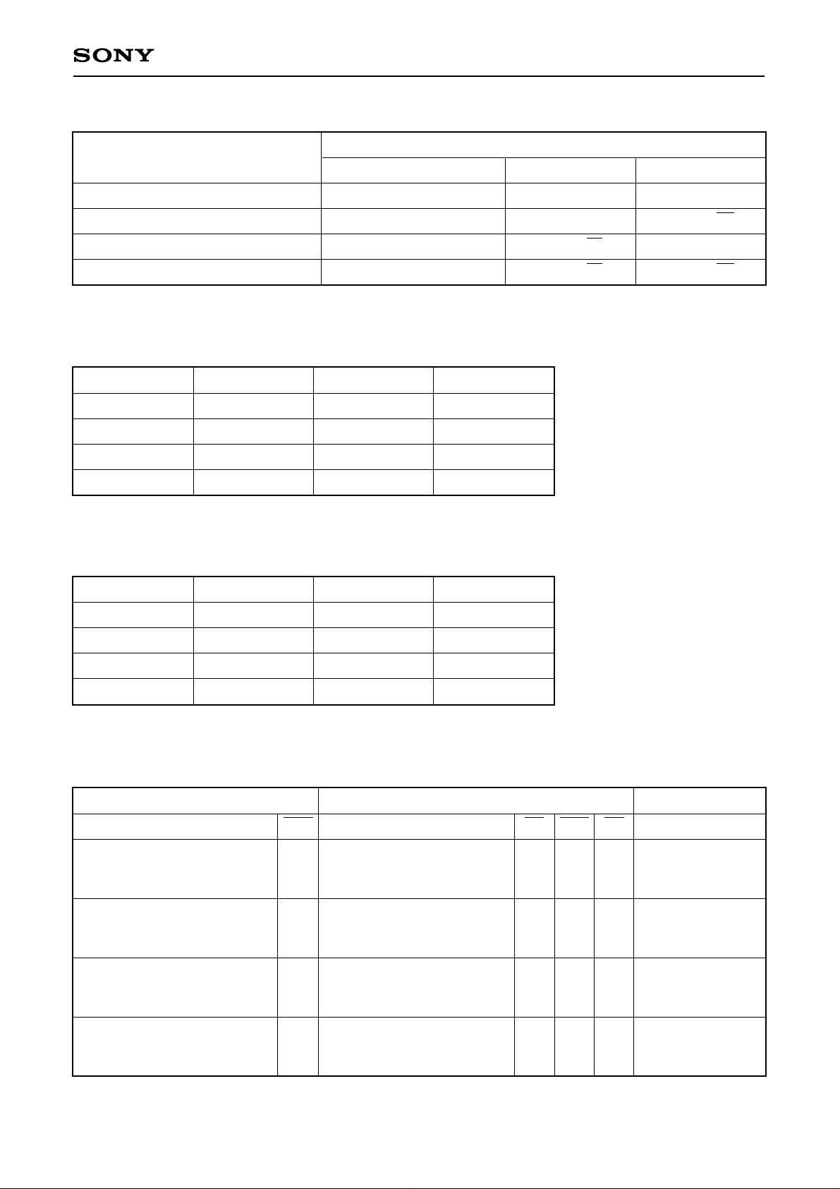
Interleaved Burst Sequence Table
CXK77V3211Q
Operation
First access, latch external address
Second access (first burst address)
Third access (second burst address)
Fourth access (third burst address)
Interleaved Burst Address Table
First address
X...X00
X...X01
X...X10
X...X11
Second address
X...X01
X...X00
X...X11
X...X10
A14 to A2
A14 to A2
latched A14 to A2
latched A14 to A2
latched A14 to A2
Third address
X...X10
X...X11
X...X00
X...X01
Address used
Fourth address
X...X11
X...X10
X...X01
X...X00
A1
A1
latched A1
latched A1
latched A1
A0
A0
latched A0
latched A0
latched A0
Linear Burst Address Table
First address
X...X00
X...X01
X...X10
X...X11
Second address
X...X01
X...X10
X...X11
X...X00
Pass-Through Truth Table
Previous cycle Present cycle Next cycle
Operation BWs Operation CE BWs OE Operation
Initial WRITE cycle, all bytes
Address = A (n – 1),
data = D (n – 1)
Initial WRITE cycle, all bytes
Address = A (n – 1),
data = D (n – 1)
Initial WRITE cycle, all bytes
Address = A (n – 1),
data = D (n – 1)
Third address
X...X10
X...X11
X...X00
X...X01
Initial READ cycle
All L
Register A (n), Q = D (n – 1)
No new cycle
All L
Q = D (n – 1)
No new cycle
All L
Q = HIGH-Z
Fourth address
X...X11
X...X00
X...X01
X...X10
H
H
L
H
L
Read D (n)
H
H
No carryover from
L
previous cycle
No carryover from
H
previous cycle
Initial WRITE cycle, one byte
Address = A (n – 1),
data = D (n – 1)
One L
No new cycle
Q = D (n – 1) for one byte
Note) Previous cycle may be either BURST or NONBURST cycle.
– 5 –
H
H
No carryover from
L
previous cycle
CXK77V3211Q
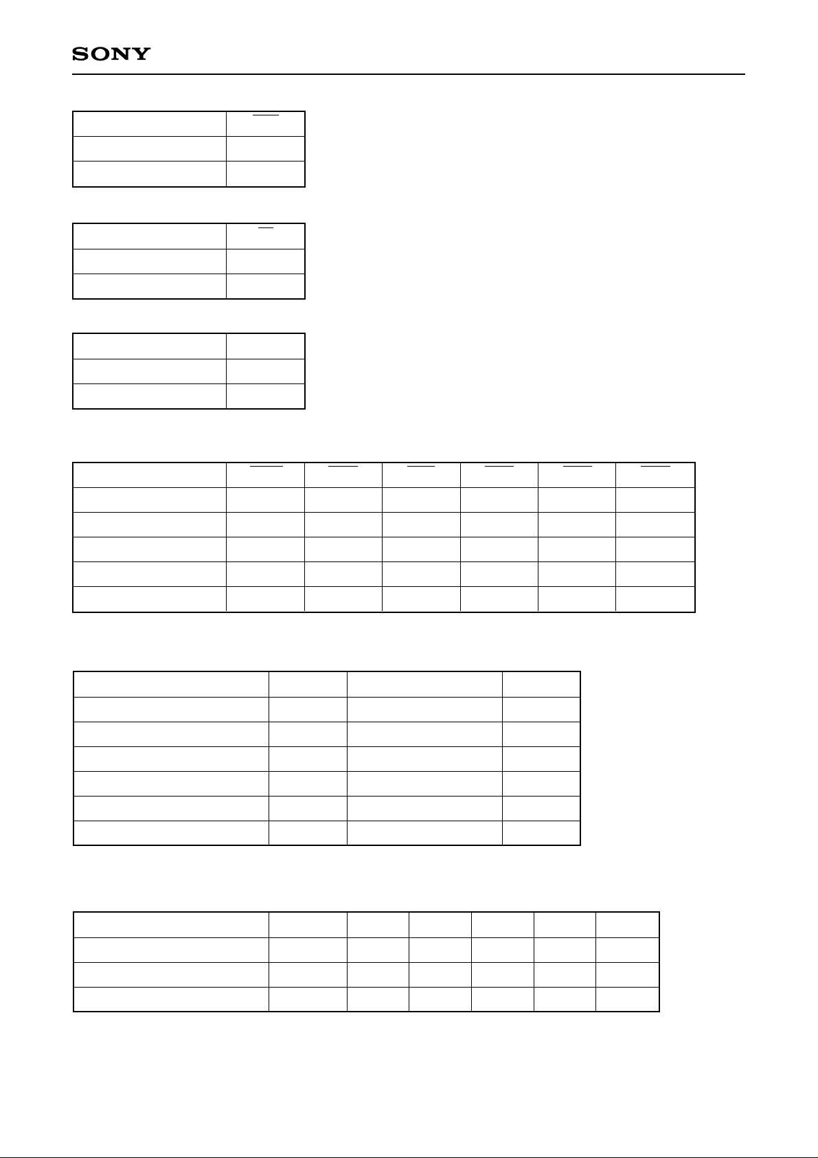
Function
Linear burst
Interleaved burst
Function
Flow-thru output
Pipelined output
Function
Powerdown to ISB1
Active
Partial Truth Table
Function
READ
LBO
L
H or NC
FT
L or NC
H
ZZ
H
L or NC
SGW
H
BWE
H
BW1
X
BW2
X
BW3
X
BW4
X
READ
WRITE byte 1
WRITE all bytes
WRITE all bytes
H
H
H
L
L
L
L
X
H
L
L
X
H
H
L
X
H
H
L
X
Absolute Maximum Rating (Ta = 25°C, GND = 0V)
Item
Supply voltage
Input voltage
Power dissipation
Operating temperature
Storage temperature
Soldering temperature · time
Symbol
VDD
VIN
PD
Topr
Tstg
Tsolder
Rating
–0.5 to +4.6
–0.5 to 6 (Max.)
1.6
0 to +70
–55 to +150
235 · 10
Unit
V
V
W
°C
°C
°C · sec
DC Recommended Operating Conditions (Ta = 0 to +70°C, GND = 0V)
H
H
L
X
Item
Supply voltage
Input high voltage
Input low voltage
Symbol
VDD
VIH
VIL
Note) 1. All voltage referenced to VSS (GND).
2. Overshoot: VIH ≤ VDD + 2.0V for t ≤ tKC/2.
Undershoot: VIL ≥ –2.0V for t ≤ tKC/2.
Min.
3.135
2.0
–0.3
– 6 –
Typ.
3.3
—
—
Max.
3.63
5.5
0.8
Unit
V
V
V
Note
1
1, 2
1, 2
 Loading...