

Sony CXA1695L Datasheet

All Band TV Tuner IC (VHF-CATV-UHF)
CXA1695L
Description
The CXA1695L is a single chip TV tuner IC which
performs as an oscillator, mixer for VHF/CATV and
UHF bands. An IF amplifier is also provided.
This IC achieves a large reduction of external parts
in addition to miniaturizing the tuner and increasing
manufacturing productivity, reliability and design
efficiency.
This IC is pin-compatible with the CXA1594L with
improvement in noise figure and oscillation stability.
Features
• On-chip oscillator and mixer for UHF band
• Low noise figure
• Reduced spurious interference
• Superior cross modulation
• Stable oscillation characteristics
• Ultra small package ensures tuner miniaturization
Applications
• CTV tuner
• CATV UP-DOWN converter
16 pin SZIP (Plastic)
Structure
Bipolar silicon monolithic IC
Absolute Maximum Ratings (Ta=25 °C)
• Supply voltage Vcc 11 V
• Storage temperature Tstg –55 to +150 °C
• Allowable power dissipation
PD 930 mW
(when mounted on board)
Operating Conditions
• Supply voltage Vcc 8.1 to 9.9 V
• Operating temperature Topr –20 to +75 °C
Block Diagram and Pin Configuration
VHF MIX
–
IF AMP
+
VHF OSC
SW
V
REG
Vcc
V OSC B
10 11
UHF IN 1
SW
1
IF OUT
Sony reserves the right to change products and specifications without prior notice. This information does not convey any license by
any implication or otherwise under any patents or other right. Application circuits shown, if any, are typical examples illustrating the
operation of the devices. Sony cannot assume responsibility for any problems arising out of the use of these circuits.
3 4 5 6 7 8 9
2
GND
VHF IN 1
VHF IN 2
MIX OU T 1
MIX OU T 2
UHF MIX
V OSC C
UHF OSC
GND
UHF IN 2
U OSC C
1615141312
U OSC B1
U OSC B2
—1—
E92Y29A51-TE
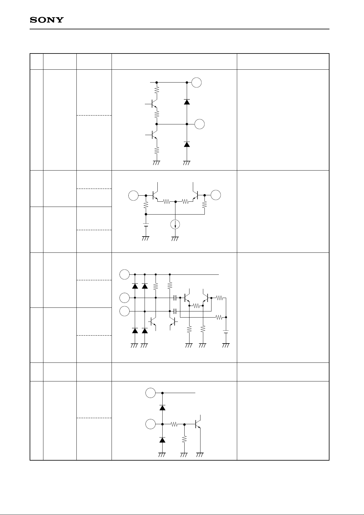
Pin Description and Equivalent Circuit
Pin
Symbol
No. voltage (V)
1 IF OUT
Typical pin
Under VHF
operation
4.4
Under UHF
operation
4.4
Equivalent circuit Description
CXA1695L
Vcc
8
55
1
IF output.
2 VHF IN 1
4 VHF IN 2
3 MIX OUT 1
5 MIX OUT 2
3.2
3.3
3.2
3.3
7.5
7.2
7.5
7.2
VHF input.
Normally a decoupling
2
3k
4
3k
capacitor is connected at pin 2
to GND and pin 4 is used for
input.
Mixer output and IF amplifier
Vcc
8
450450
3
5
5k
5k
input.
6 GND
7SW
0
3V or more
0.4V or less
GND
Vcc
8
UHF/VHF switch pin.
Connect 9V source through
about a 10kΩ resister for VHF
reception; 0V or leave open for
7
40k
60k
UHF.
—2—
CXA1695L
Pin
Symbol
No. voltage (V)
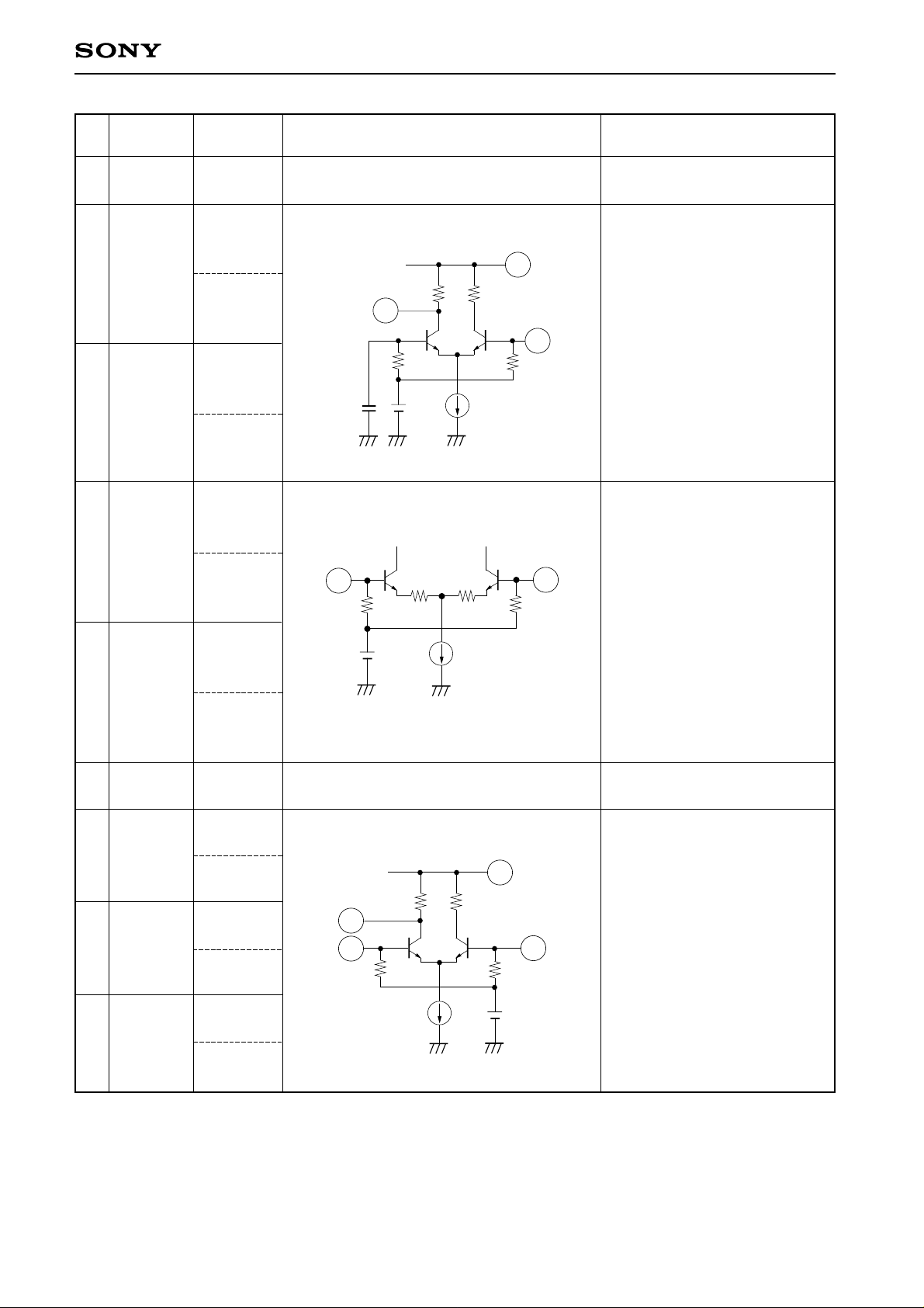
8 Vcc
9 V OSC B
Typical pin
9.0
3.5
3.7
11 V OSC C
6.7
9.0
10 UHF IN 1
3.3
3.1
12 UHF IN 2
3.3
25p
10
Equivalent circuit Description
Power supply
VHF oscillator.
Vcc
8
800
11
9
3k
3k
UHF input.
The balanced input to Pins 10
and 12, or a decoupling
capacitor is connected at Pin
12
3k
3k
12 to GND and Pin 10 is used
for input.
13 GND
14 U OSC C
15 U OSC B2
16 U OSC B1
3.1
0
9.0
6.5
3.6
3.4
3.6
3.4
GND
UHF oscillator.
Vcc
8
800
14
16
3k
15
3k
—3—
 Loading...