

Sony CXA1665AM-S, CXA1665AM Datasheet

– 1 –
CXA1665AM/AM-S
E95826A63-ST
All Band TV Tuner IC (VHF-CATV-UHF)
Description
The CXA1665AM/AM-S is a single chip TV tuner
IC which performs as an oscillator, mixer for
VHF/CATV and UHF bands. An IF amplifier is also
provided.
This IC adopts a 16-pin SOP package in response
to the trend toward miniaturizing the tuner and
automatic IC mounting. This IC achieves a large
reduction of external parts in addition to
miniaturizing the tuner and increasing manufacturing
productivity, reliability and design efficiency.
Features
• On-chip oscillator and mixer for UHF band
• Low noise figure
• Reduced spurious interference
• Superior cross modulation distortion
• Stable oscillating characteristics
Absolute Maximum Ratings (Ta = 25°C)
• Supply voltage VCC 11 V
• Storage temperature Tstg –65 to +150 °C
• Allowable power dissipation PD 980 mW
(When mounted on a board)
Block Diagram and Pin Configuration (Top View)
Structure
Bipolar silicon monolithic IC
Applications
• CTV tuner
• CATV UP-DOWN converter
• FM detector for 2nd IF satellite broadcasts
Operation Conditions
• Supply voltage VCC 9.0 ± 0.9 V
• Operating temperature Topr –20 to +75 °C
Sony reserves the right to change products and specifications without prior notice. This information does not convey any license by
any implication or otherwise under any patents or other right. Application circuits shown, if any, are typical examples illustrating the
operation of the devices. Sony cannot assume responsibility for any problems arising out of the use of these circuits.
16 pin SOP (Plastic)
SW
UHF OSC UHF MIX
VHF MIX
IF
AMP
–
+
VHF OSC
VOSC C
UOSC B2
UOSC E2
UOSC E1
UOSC B1/SW
REG
UHF IN2
UHF IN1
VOSC B
GND
MIX OUT1
MIX OUT2
IF OUT
V
CC
VHF IN1
VHF IN2
2
3
4
5
7
8
1
9
10
11
12
13
14
15
16
6
V.
REG
– 2 –
CXA1665AM/AM-S
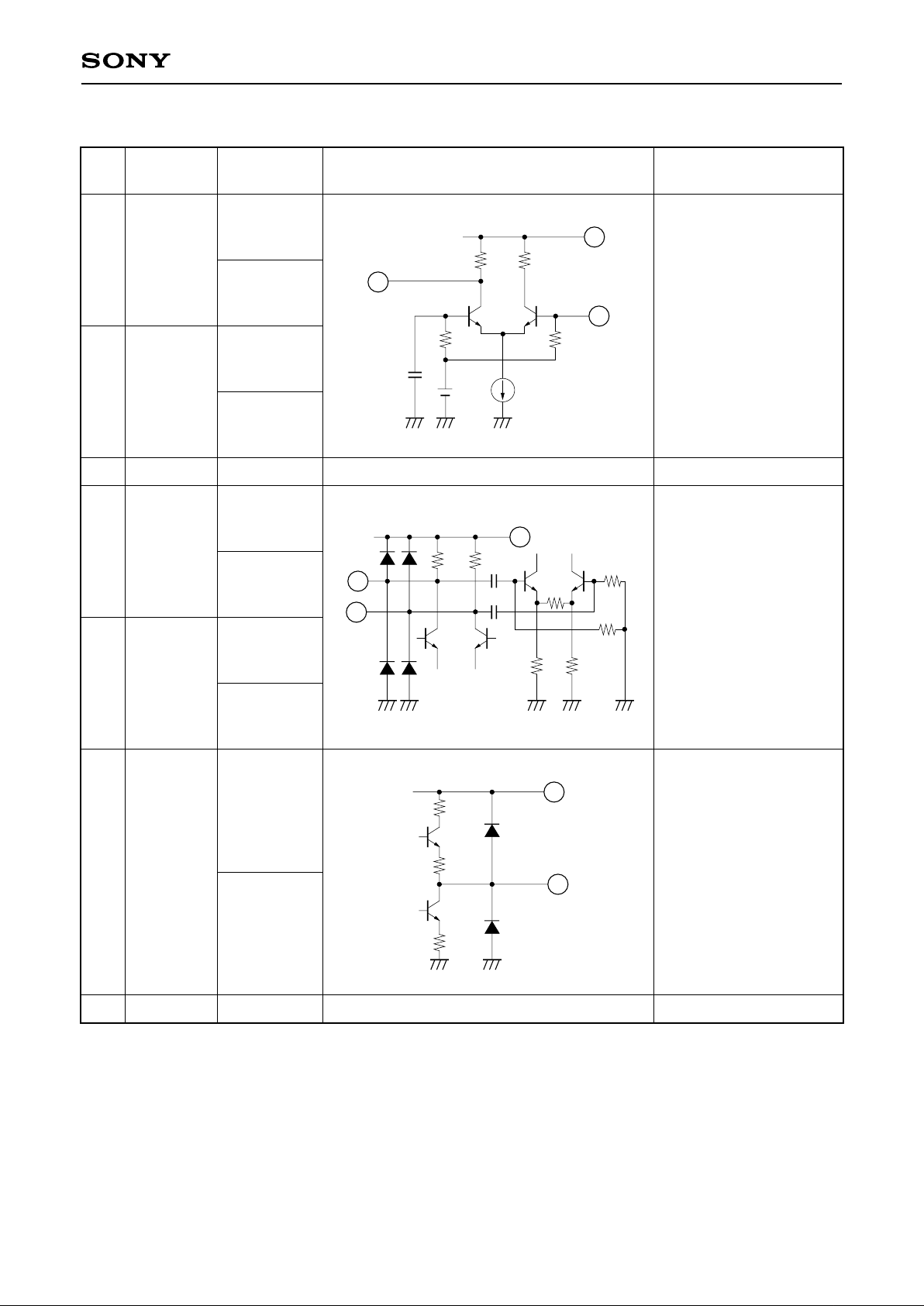
Pin Description and Equivalent Circuit
Pin
No.
Symbol
Typical
voltage (V)
Equivalent circuit Description
116VOSC B
VOSC C
34MIX OUT1
MIX OUT2
Under VHF
operating; 3.5
Under UHF
operating; 3.7
6.7
9.0
7.5
7.3
7.5
7.3
VHF ocsillator.
Mixer output and IF
amplifier input.
5 IF OUT
4.5
4.5
IF output.
2 GND
0
GND
6VCC
9
Power supply.
16
6
1
800
25P
3k
V
CC
3k
6
VCC
450
5k
3
4
450
5k
5
6
VCC
55
– 3 –
CXA1665AM/AM-S
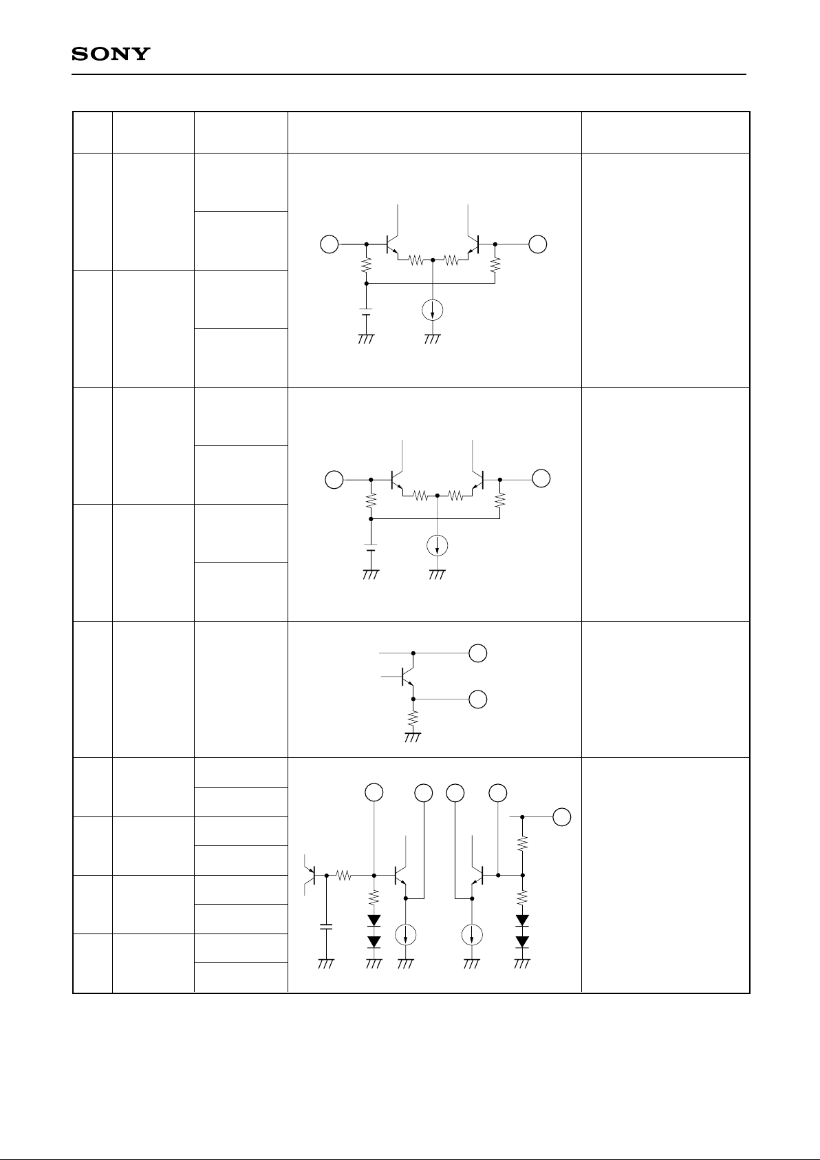
78VHF IN1
VHF IN2
3.2
3.3
3.2
3.3
VHF input; normally a
decoupling capacitor is
connected at Pin 7 to
GND and Pin 8 is used
for input.
910UHF IN1
UHF IN2
3.3
3.2
3.3
3.2
UHF input.
The balanced input to
Pins 9 and 10, or a
decoupling capacitor is
connected at Pin 10 to
GND and Pin 9 is used
for input.
11 REG
6
12
UOSC
B1/SW
13 UOSC E1
14 UOSC E2
15 UOSC B2
0
0
3.2
3.7
3.4
2.6
2.6
3.4
Regulator output.
UHF oscillator.
Pin 12 is used for both
U/V switches.
3k
3k
8
7
3k3k
10
9
11
6
V
CC
6
8k
8k
12
13
14
15
40k
VCC
20k
Pin
No.
Symbol
Typical
voltage (V)
Equivalent circuit Description
 Loading...