

Sony CXA1600P, CXA1600M Datasheet
—1—
E92311B8X
Sony reserves the right to change products and specifications without prior notice. This information does not convey any license by
any implication or otherwise under any patents or other right. Application circuits shown, if any, are typical examples illustrating the
operation of the devices. Sony cannot assume responsibility for any problems arising out of the use of these circuits.
Absolute Maximum Ratings (Ta=25 °C)
• Supply voltage VCC 7V
• Operating temperature Topr –20 to +75 °C
• Storage temperature Tstg –65 to +150 °C
Operating Conditions
Supply voltage VCC 1.8 to 4.5 V
Description
The CXA1600M/P is an 8-pin single-chip bipolar IC
for AM radios. This IC includes all functions from
the front-end to the power amplifier.
The CXA1600M/P doesn’t require any external
filter, making external ceramic filter attachment
unnecessary.
Features
• EIAJ output=100 mW (typ.)
(VCC=3 V, RL=8 Ω)
• Built-in electrical volume control.
• No ceramic filter required.
• Few peripheral components.
Applications
AM radio
Structure
Bipolar silicon monolithic IC
8-pin Single-chip AM Radio with Built-in Power Amplifier
CXA1600M CXA1600P
8 pin SOP (Plastic) 8 pin DIP (Plastic)
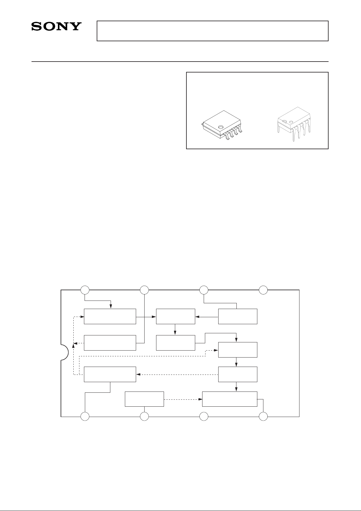
Block Diagram
RF AMP
OVERLOAD AGC
AGC
VOL
AF POWER AMP
IF DET
IF AMP
OSCMIXER
BPF
RF IN OL AGC LO OSC V
CC
AGC VOL GND SP OUT
1 2 3 4
5678
CXA1600M/P
For the availability of this product, please contact the sales office.
—2—
CXA1600M/P
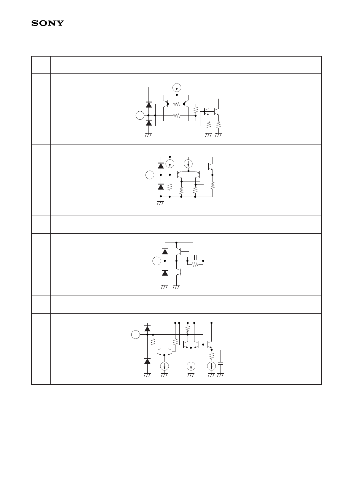
Pin Description VCC=3 V
No. Symbol
Voltage
Equivalent Circuit Description
(typ.)
1
2
3
4
5
6
AGC
VOL
GND
SP OUT
VCC
LO OSC
0.61 V
0.1 V
0 V
1.28 V
3 V
VCC
AGC
V
CC
GND
1
VCC
GND
VOL
2
VCC
GND
SP OUT
4
VCC
GND
LO OSC
6
Connect with a capacitor.
Connect to the midpoint of the
volume control.
Ground
Audio output.
Connect with a capacitor.
Power supply
Oscillation output.
Connect with an oscillation coil.
—3—
CXA1600M/P
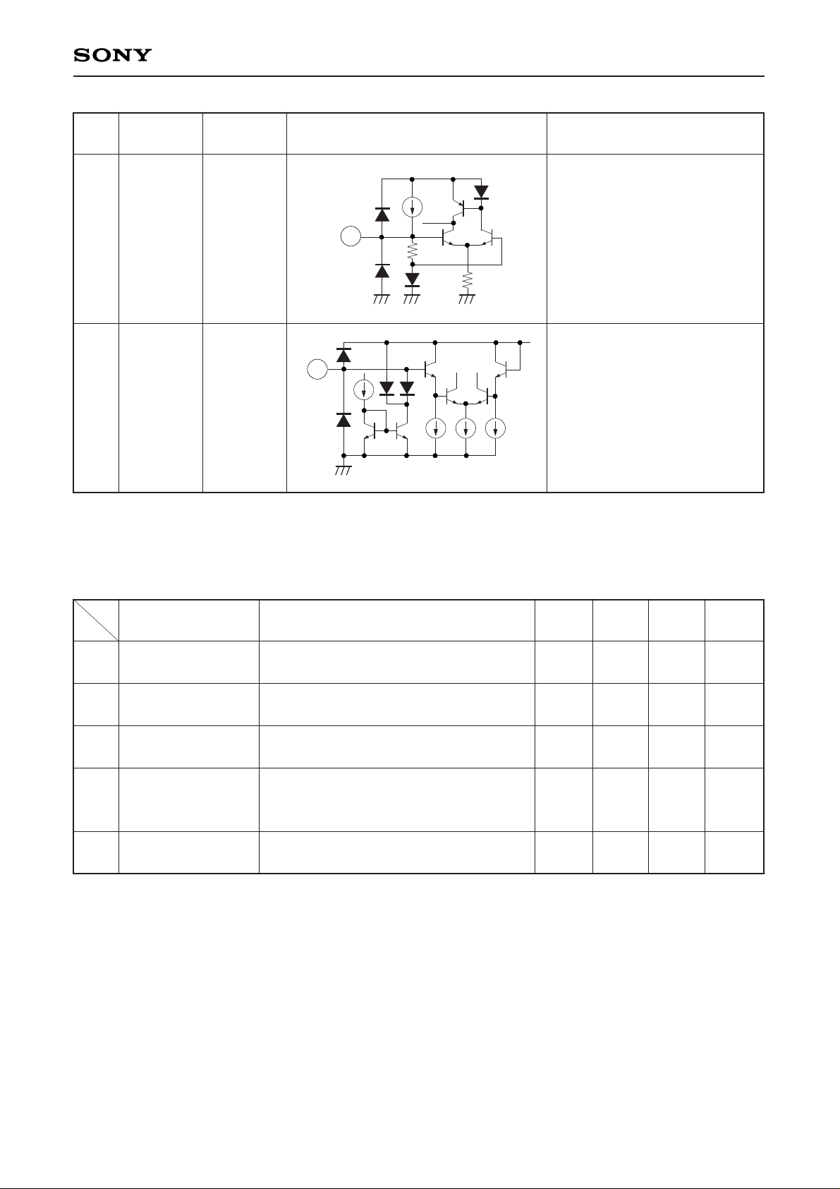
No. Symbol
Voltage
Equivalent Circuit Description
(typ.)
7
8
OL AGC
RF IN
0.62 V
3 V
VCC
GND
OL AGC
7
VCC
GND
RF IN
8
Connect with a capacitor.
RF input.
Connect with the antenna circuit.
Electrical Characteristics VCC=3 V, Ta=25 °C
1
2
3
4
5
Item
Non-signal
circuit current
EIAJ output
(with 8 Ω load)
Volume attenuation
Overall noise level
Selectivity
Test conditions
No signal
f=1 MHz, fMOD=1 kHz, 30 %
Vin=90 dBµV
f=1 MHz, fMOD=1 kHz, 30 %
Vin=90 dBµV, Volume=minimum
Short circuit at RF IN with a 1µF
capacitor. Measure the level at SP OUT.
Volume=maximum
f=1.010 MHz, fMOD=1 kHz, 30 %
Vin=35 dBµV.
Min. Typ. Max. Unit
4.8 6 10 mA
80 100 mW
–70 –65 dBm
–25 –15 dBm
14 19 dB
 Loading...