

CXA1310AQ
Single Chip Processing for CCD Monochrome Camera
Description
The CXA1310AQ is designed to perform the basic
signal processing in CCD monochrome cameras with
a single chip. This bipolar lC is most suitable for
compact usage and low power consumption.
Features
• Processing from CCD output to 75Ω video output
with a single chip
• Wide variable AGC (4 to 32dB Typ.)
• Built-in operational amplifier for AGC loop
• 75Ω line capacitance minimized using sag compen-
sation function
• Variable white clip level realize wide dynamic range
(140 IRE)
Application
CCD monochrome camera
Structure
Bipolar silicon monolithic IC
Absolute Maximum Ratings (Ta = 25°C)
• Supply voltage VCC 7V
•Storage temperature Tstg –65 to +150 °C
• Operating temperature Topr –20 to +75 °C
• Allowable power dissipation PD 500 mW
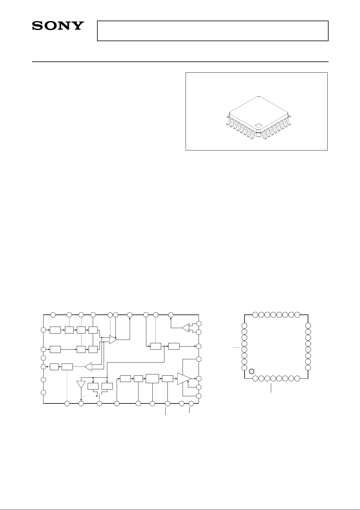
32 pin QFP (Plastic)
Block Diagram and Pin Configuration
21
S/H S/HCLP2
9
HSD1
LINEAR
20
HSD2
AGC CONT
16
AGC
7
DRIVER IN
AGC OUT
12
CLP1 WC
AGC MAX
14
γ 2γ 1
8
γ OUT
DATA
GND3
IRIS
CC1
V
GND1
CLP2
25
CLP2 S/H S/H S/H
23
PG
22
26
27
15
3
SHP
24
CLP1BLK
28
IRIS CLP
11
6
WC CONT
γ IN
γ CLP
10
CLP1 BLK
SETUP
BLK
5
SET CONT
SYNC
4
Operating Conditions
Supply voltage VCC 4.75 to 5.25 V
OP OUT
17
18
OP IN–
19
OP IN+
13
DET OUT
31
CC2
V
32
VIDEO
1
SAG
GND2
2
29
BLK
SYNC
DRIVE
30
CLP1
CLP2
GND3
IRIS
IRIS CLP
BLK
CLP1
CC2
V
VIDEO
SHD1
DATA
PG
SHP
23
21
22
24
25
26
27
28
29
30
31
32
1
SAG
2
GND2
3
GND1
4
SYNC
20
5
OP IN–
OP IN+
SHD2
19
18
6
7
WC CONT
DRIVER IN
SET CONT
OP OUT
17
8
γ OUT
16
15
14
13
12
11
10
9
AGC CONT
CC1
V
AGC MAX
DET OUT
AGC OUT
γ IN
γ CLP
LINEAR
Sony reserves the right to change products and specifications without prior notice. This information does not convey any license by
any implication or otherwise under any patents or other right. Application circuits shown, if any, are typical examples illustrating the
operation of the devices. Sony cannot assume responsibility for any problems arising out of the use of these circuits.
– 1 –
E89Z21A78-PS
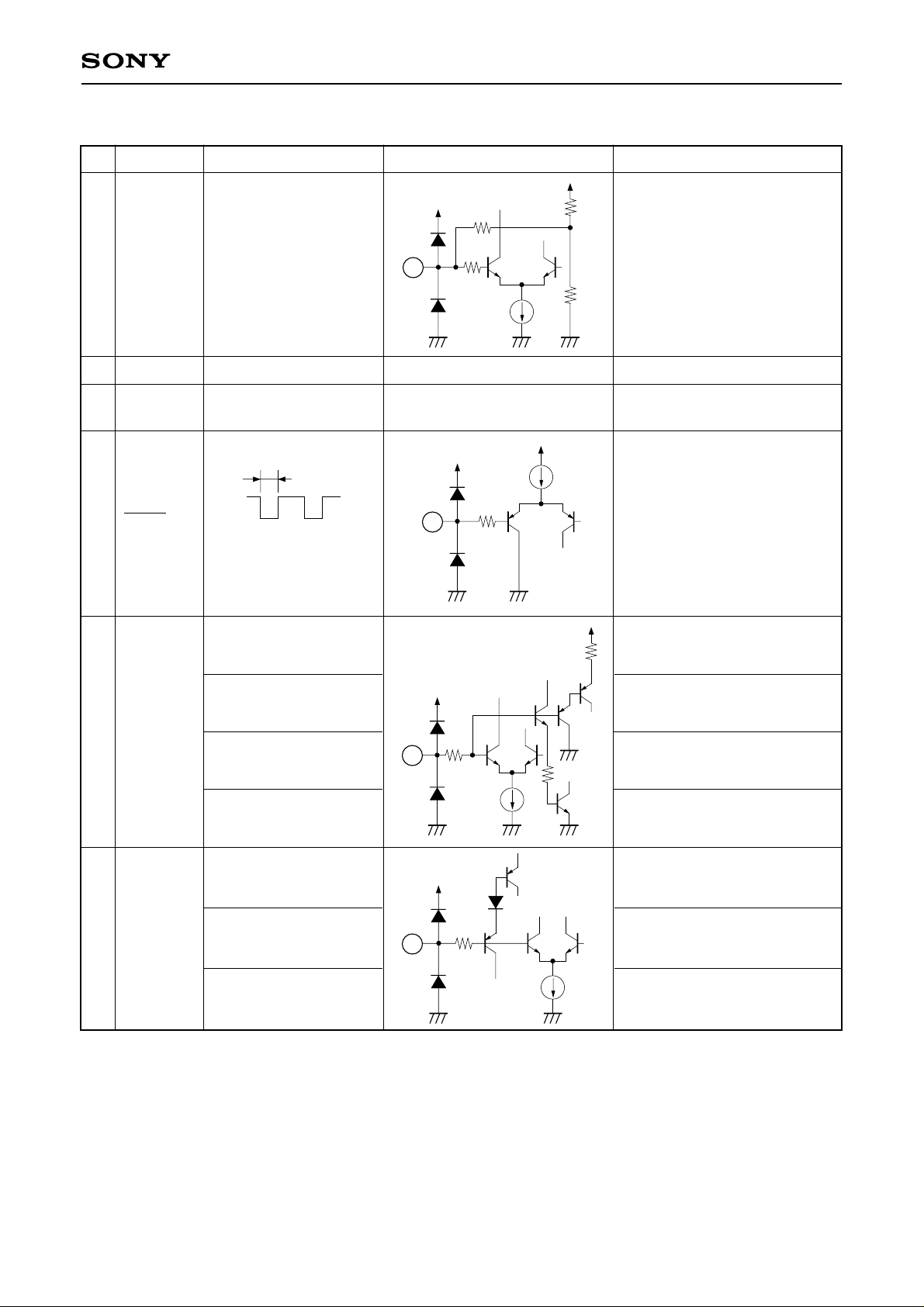
Pin Description
CXA1310AQ
No. Symbol I/O signal
Inputs VIDEO OUT
1
SAG
23GND2
GND1
4
SYNC
through capacitor
∗
GND
∗
GND
T
High: 4.5V and above
Low: 0.5V and below
T: 5µs
Equivalent circuit
150Ω
1
150Ω
10k
Input pin of sag compensation
signal
6k
400µA
Description
GND for driver and IRIS
GND for other than driver,
sample hold and IRIS
20µA
4
∗
150Ω
Sync pulse input pin
(active at Low)
5
SET CONT
6
WC CONT
∗
GND
2 to 3.5V
∗
VCC
∗
GND
2 to 3.5V
Set-up level adjusting pin
Turns to preset mode 1
∗
5
150Ω
40µA
Control mode
Turns to preset mode 2
White clip level adjusting pin
6
150Ω
∗
40µA
Preset mode
Control mode
∗
External applied voltage
– 2 –
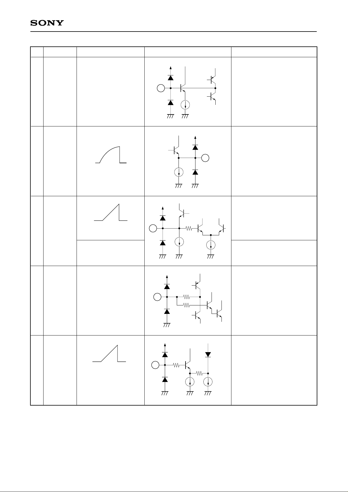
CXA1310AQ
No. Symbol I/O signal
7
DRIVER IN
γ OUT
8
Input γ OUT through
capacitor or LINEAR
DC 2V
9
LINEAR
VCC
DC 1.8V
∗
Equivalent circuit
7
480µA
9
150Ω
480µA
40µA
Description
Input pin to driver
Gamma correction signal
output pin.
8
Outputs γ 1 when Pin 9 is at
OPEN
Outputs γ 2 when Pin 9 is
turnedto 5V
Linear signal (γ-OFF signal)
output pin
15µA
Pin 8 output signal turns to γ 2
output
10
11
γ CLP
γ IN
Input DC permissible
range
DC2 to 3V
∗
11
10
150Ω
150Ω
150Ω
80µA 160µA
– 3 –
Capacitor connecting pin for
gamma input clamp
Input pin of the gamma
correction circuit
∗
External applied voltage
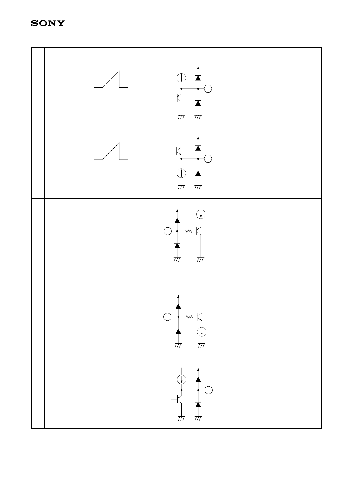
CXA1310AQ
No. Symbol I/O signal
12
AGC OUT
Vp-p MAX 1300mV
Vp-p TYP 500mV
DC 2.55V
13
DET OUT
MAX 1500mV
TYP 500mV
DC 2V
Equivalent circuit
700µA
320µA
12
13
20µA
Description
Output pin of signal passed
through AGC
Output pin of AGC detection
signal
14
15
16
17
AGC MAX
VCC1
AGC
CONT
OP OUT
DC
5V
DC
∗
14
150Ω
∗
Maximum gain setting pin of
AGC amplifier
Power supply for other than
driver and IRIS
∗
16
150Ω
120µA
320µA
17
Gain control pin of AGC
amplifier
Output pin of the operational
amplifier
– 4 –
∗
External applied voltage
 Loading...