

Page 1

CVX-V18NS/V18NSP
SERVICE MANUAL
Ver 1.0 1999. 04
NTSC model: CVX-V18NS
PAL model : CVX-V18NSP
Printed wiring boards and schematic diagrams are not mentioned
because mounted boards are replaced to repair this model.
US Model
Canadian Model
CVX-18NS
AEP Model
CVX-V18NSP
SPECIFICATIONS
MICROFILM
COLOR VIDEO CAMERA
Page 2
SER VICE NOTE
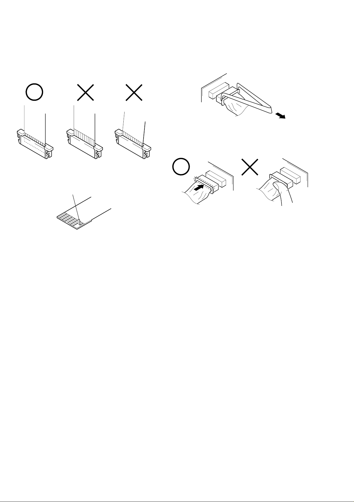
• NOTE FOR REPAIR
Make sure that the flat cable and flexible board are not cracked of
bent at the terminal.
Do not insert the cable insufficiently nor crookedly.
Cut and remove the part of gilt
which comes off at the point.
(Take care that there are some
pieces of gilt left inside)
When remove a connector, don’t pull at wire of connector.
Be in danger of the snapping of a wire.
When installing a connector, don’t press down at wire of connector.
Be in danger of the snapping of a wire.
SAFETY CHECK-OUT
After correcting the original service problem, perform the following
safety checks before releasing the set to the customer.
1. Check the area of your repair for unsoldered or poorly-soldered connections. Check the entire board surface for solder
splashes and bridges.
2. Check the interboard wiring to ensure that no wires are
“pinched” or contact high-wattage resistors.
3. Look for unauthorized replacement parts, particularly transistors, that were installed during a previous repair. Point them
out to the customer and recommend their replacement.
4. Look for parts which, though functioning, show obvious signs
of deterioration. Point them out to the customer and recommend their replacement.
5. Check the B+ voltage to see it is at the values specified.
6. Flexible Circuit Board Repairing
• Keep the temperature of the soldering iron around 270 ˚C
during repairing.
• Do not touch the soldering iron on the same conductor of
the circuit board (within 3 times).
• Be careful not to apply force on the conductor when sol-
dering or unsoldering.
– 2 –
Page 3

TABLE OF CONTENTS
Section Title Page Section Title Page
SERVICE NOTE...................................................................... 2
1. GENERAL
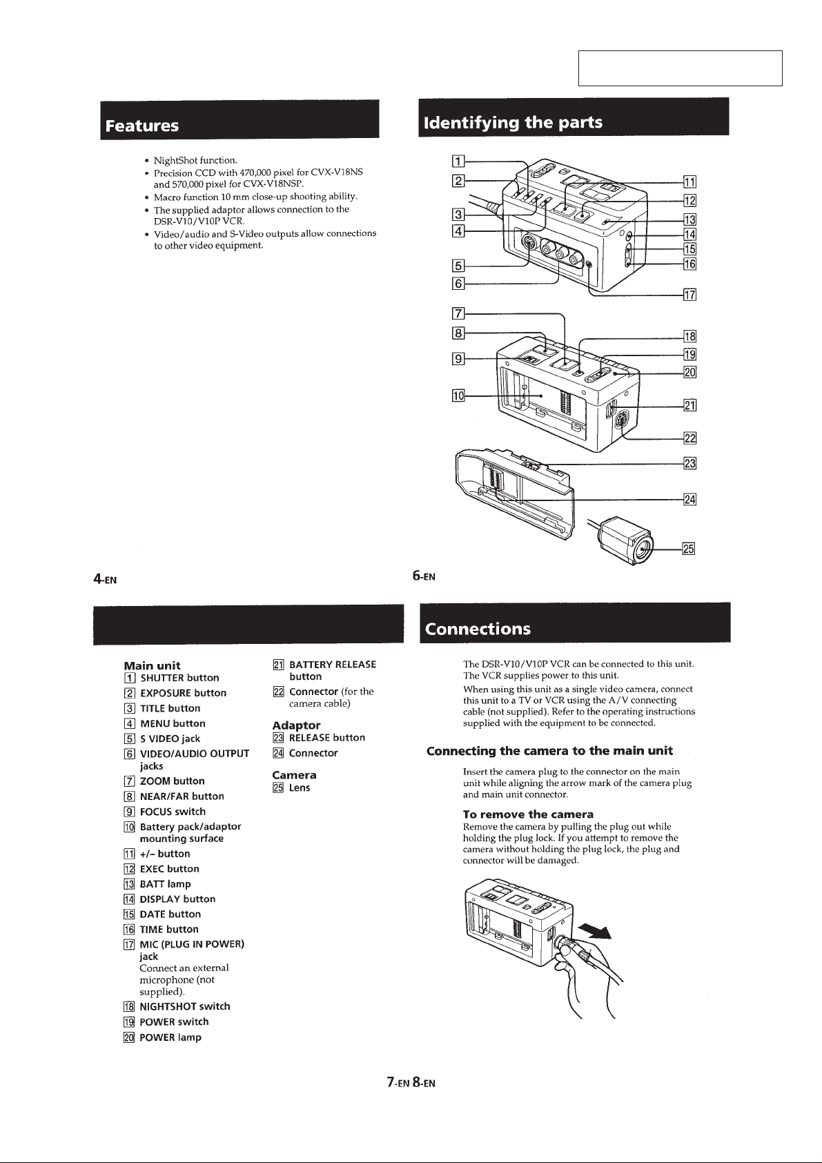
Features ........................................................................ 1-1
Identifying the Parts ...................................................... 1-1
Connections .................................................................. 1-1
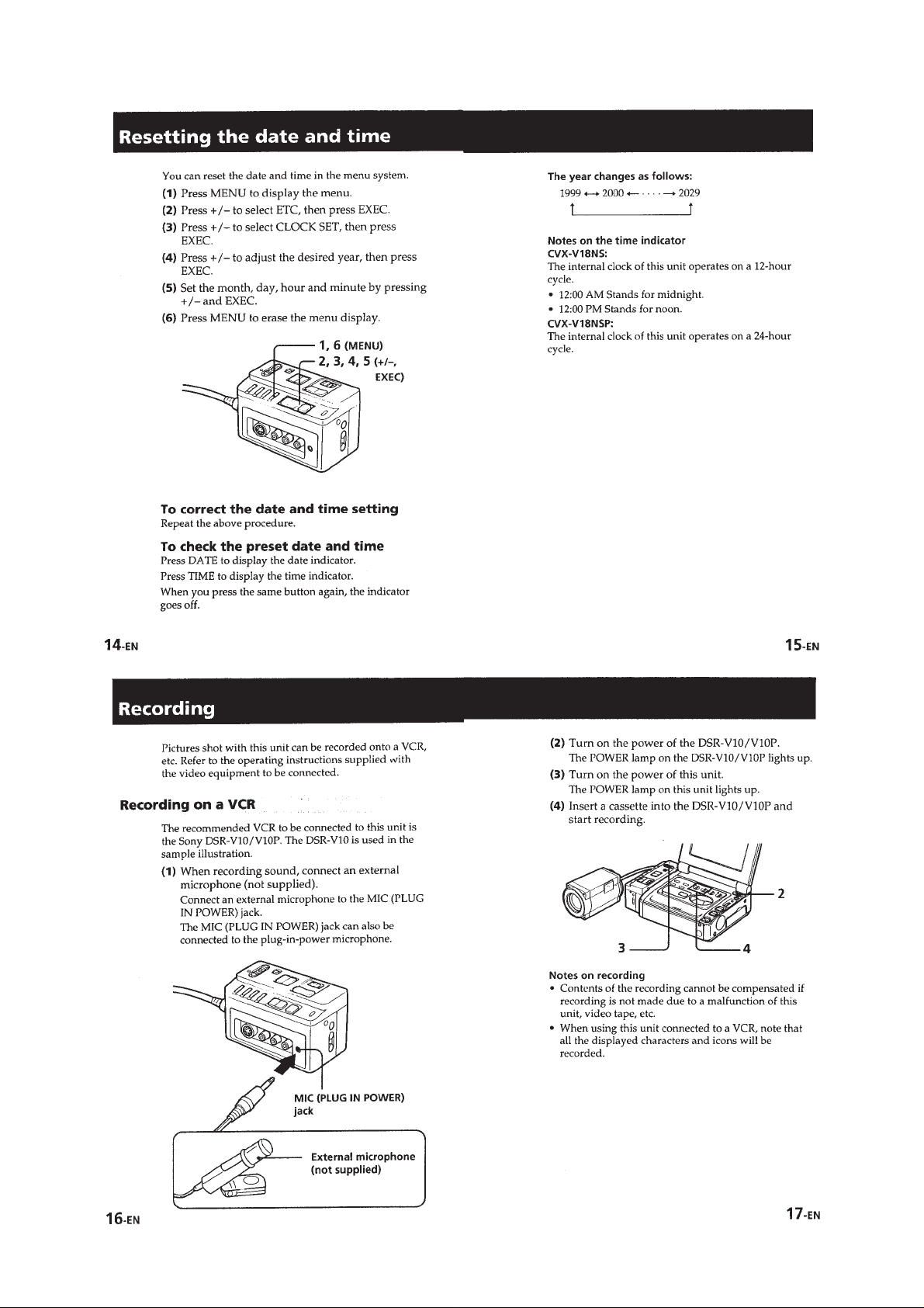
Resetting the Data and Time ........................................ 1-3
Recording ...................................................................... 1-3
Using Various Features................................................. 1-5
2. DISASSEMBLY
2-1. Cabinet (Upper) Block Ass’y ......................................... 2-2
2-2. Cabinet (Rear) Block Ass’y ........................................... 2-2
2-3. VW-1 Board, Battery Terminal Board............................ 2-2
2-4. DT-106/VA-108 Board ................................................... 2-2
2-5. CN-116 Board ............................................................... 2-3
2-6. Cabinet (F/B) Ass’y ....................................................... 2-3
2-7. Cabinet (R) Ass’y .......................................................... 2-3
2-8. IF-73 Board ................................................................... 2-3
2-9. Cabinet (L) Ass’y ........................................................... 2-4
2-10. Motor (IR Use)............................................................... 2-4
2-11. Connection Cord ........................................................... 2-4
2-12. IR-34/35 Board .............................................................. 2-4
2-13. SE-93 Board .................................................................. 2-5
2-14. VC-211 Board................................................................ 2-5
2-15. Lens Device................................................................... 2-5
2-16. Focus/Zoom Stepping Motor......................................... 2-5
2-17. Circuit Boards Location ................................................. 2-6
3. BLOCK DIAGRAMS
3. D Page Table ................................................................. 5-7
4. E Page Table ................................................................. 5-7
5. F Page Table.................................................................. 5-7
5-3. Electrical Adjustments ................................................... 5-8
1. Y Out Level Adjustment................................................. 5-8
2. C Out Level Adjustment ................................................ 5-8
3. 28 MHz origin Oscillation Adjustment ........................... 5-9
5-4. Camera System Adjustment ......................................... 5-10
1. Lens T ype Adjustment................................................... 5-10
2. G-CAM Flip Adjustment................................................. 5-10
3. G-CAM Version Adjustment .......................................... 5-11
4. HALL Adjustment........................................................... 5-12
5. Flange Back Adjustment
(Using the Mini-pattern Box) ......................................... 5-13
6. Flange Back Adjustment
(Using the Flange Back Adjustment Chart and
the Subject More than 500 m away) ............................. 5-14
6-1. Flange Back Adjustment (1).......................................... 5-14
6-2. Flange Back Adjustment (2).......................................... 5-14
7. Flange Back Check ....................................................... 5-15
8. Picture Frame Setting ................................................... 5-16
9. Color Reproduction Adjustment .................................... 5-17
10. IRIS IN/OUT Adjustment ............................................... 5-18
11. Auto White Balance Standard Data Input..................... 5-19
12. Auto White Balance Adjustment ................................... 5-19
13. White Balance Check .................................................... 5-20
6. REPAIR PARTS LIST
6-1. Exploded Views ............................................................. 6-1
6-1-1. Main Unit Section ..................................................... 6-1
6-1-2. Camera Head Section-1 .......................................... 6-2
6-1-3. Camera Head Section-2 .......................................... 6-3
6-2. Electrical Parts List........................................................ 6-4
3-1. Overall Block Diagram................................................... 3-1
3-2. Camera Block Diagram ................................................. 3-5
3-3. Camera Control (1/2) Block Diagram ........................... 3-9
3-4. Camera Control (2/2) Block Diagram ........................... 3-11
3-5. Video Out, Audio Block Diagram .................................. 3-13
3-6. Power (MAIN UNIT) Block Diagram ............................. 3-15
3-7. Power (CAMERA) Block Diagram ................................ 3-17
4. SCHEMATIC DIAGRAMS
4-1. Frame (1/2) Schematic Diagram................................... 4-1
4-2. Frame (2/2) Schematic Diagram................................... 4-3
5. ADJUSTMENTS
5-1. Preparations Before Adjustment ................................... 5-1
5-1-1. List of Service Tools ................................................. 5-1
5-1-2. Preparations ............................................................. 5-2
5-1-3. Precautions .............................................................. 5-3
1. Setting the Switch ......................................................... 5-3
2. Order of Adjustments .................................................... 5-3
3. Subjects......................................................................... 5-3
5-1-4. Adjusting Remote Commander................................ 5-4
1. Used Adjusting Remote Commander ........................... 5-4
2. Precautions Upon Using the Adjusting Remote
Commander................................................................... 5-4
5-1-5. Data Processing ....................................................... 5-5
5-1-6. Adjusting Items when Replacing a Board or
5-2. Initialization of D, E, F Page Data ................................. 5-6
Main Parts ................................................................ 5-5
1. Initializing D, E, F Page Data........................................ 5-6
2. Modification of D, E, F Page Data ................................ 5-6
– 3 –
Page 4
SECTION 1
GENERAL
CVX-V18NS/V18NSP
This section is extracted from CVXV18NS/V18NSP instruction manual.
1-1
Page 5
1-2
Page 6
1-3
Page 7
1-4
Page 8
1-5
Page 9
1-6
Page 10
1-7
1-7 E
Page 11
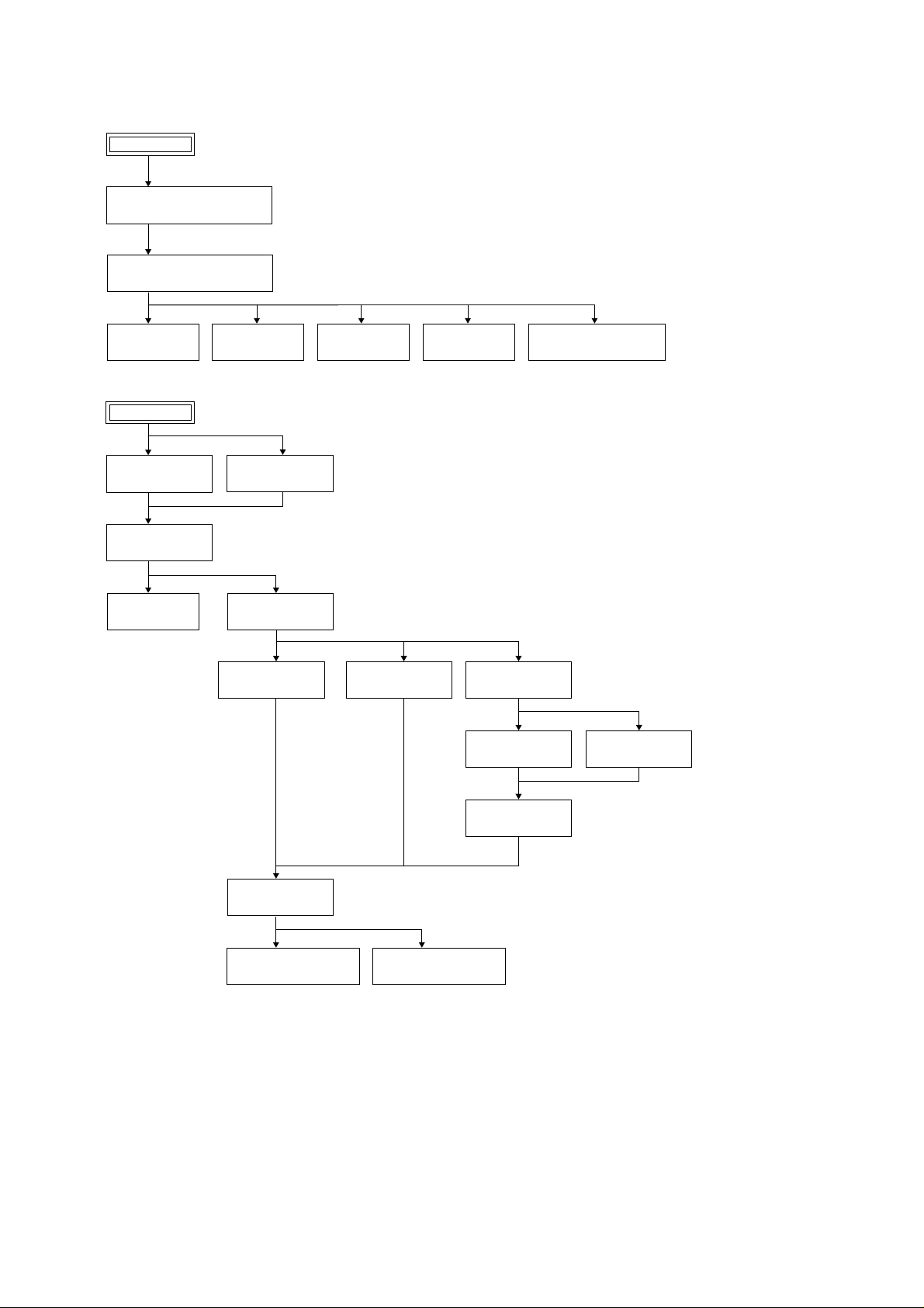
DISASSEMBLY
• This set can be disassembled in the order shown below.
Main Unit
Cabinet (Upper) Block Ass’y
(Page 2-2)
Cabinet (Rear) Block Ass’y
(Page 2-2)
CVX-V18NS/V18NSP
SECTION 2
CN-116 Board
(Page 2-3)
Camera Head
Cabinet (F) Ass’y
(Page 2-3)
Cabinet (R) Ass’y
(Page 2-3)
IF-73 Board
(Page 2-3)
DT-106 Board
(Page 2-2)
Cabinet (B) Ass’y
(Page 2-3)
Cabinet (L) Ass’y
(Page 2-4)
Motor (IR Use)
(Page 2-4)
VA-108 Board
(Page 2-2)
IR-34 Board
(Page 2-4)
VW-1 Board
(Page 2-2)
Connection Code
(Page 2-4)
IR-35 Board
(Page 2-4)
Battery Terminal Board
(Page 2-2)
SE-93 Board
(Page 2-5)
Lens Device
(Page 2-5)
Focus Stepping Motor
(Page 2-5)
VC-211 Board
(Page 2-5)
Zoom Stepping Motor
(Page 2-5)
2-1
Page 12
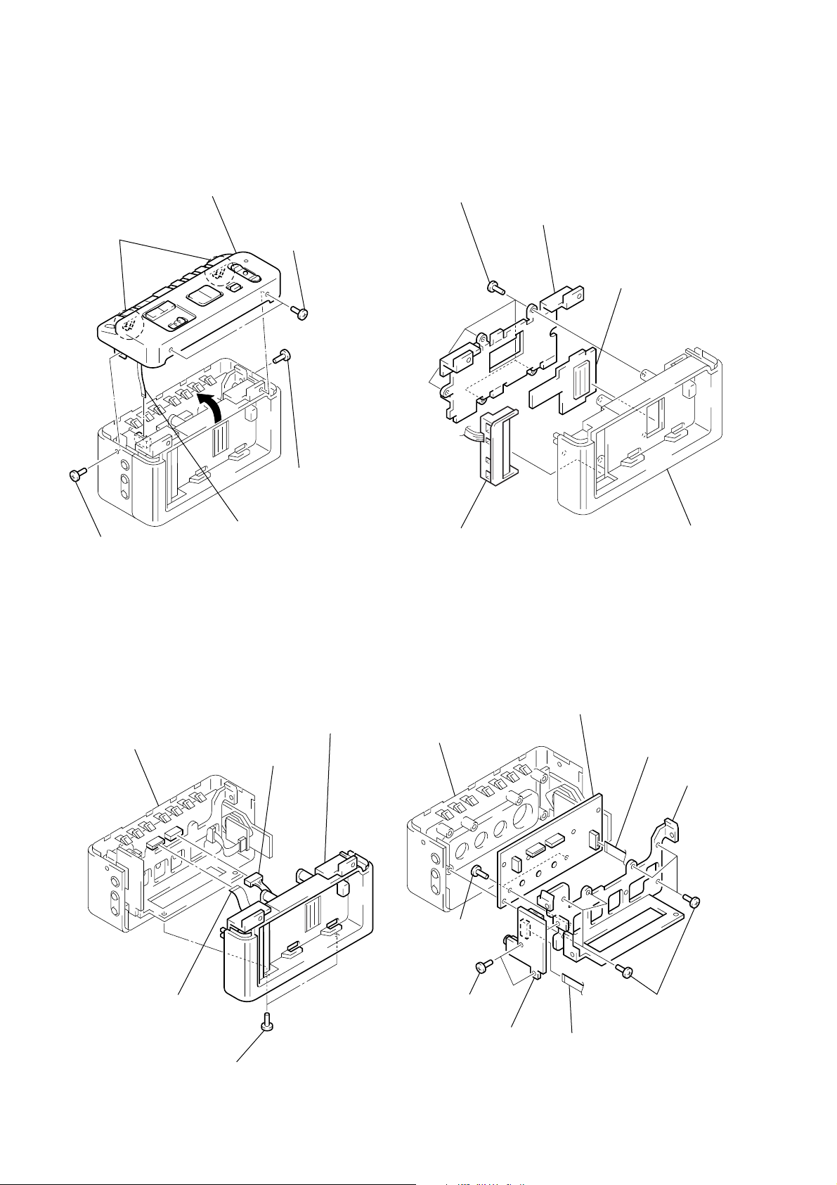
Note: Follow the disassembly procedure in the numerical order given.
2-1. CABINET (UPPER) BLOCK ASS’Y 2-3. VW-1 BOARD, BATTERY TERMINAL
BOARD
5 Cabinet (upper) block ass’y
4 Two claws
1 Screw
(M2)
3 Two screws
(M2)
2 Screw
(M2)
6 Flat cable (FFC-272)
(CN997)
1 Five screws
2 Terminal board retainer
4 Battery terminal board
3 VW-1 board
VW-1
Cabinet (back) ass’y
2-2. CABINET (REAR) BLOCK ASS’Y
4 Cabinet (rear) block ass’y
Cabinet (front) block ass’y
VA-108 board
1 Flat cable (FFC-275)
(CN882)
3 Two screws
2 Connector
(CN881)
CN-116
(M2)
2-4. DT-106/VA-108 BOARD
8 VA-108 board
Cabinet (front) ass’y
VA-108 board
7 Two screws
(M2)
5 Two screws
(M2)
6 DT-106 board
DT-106
4 Flat cable (FFC-273)
(CN996)
1 Flat cable (FFC-274)
(CN883)
3 Main frame
2 Six screws
2-2
Page 13
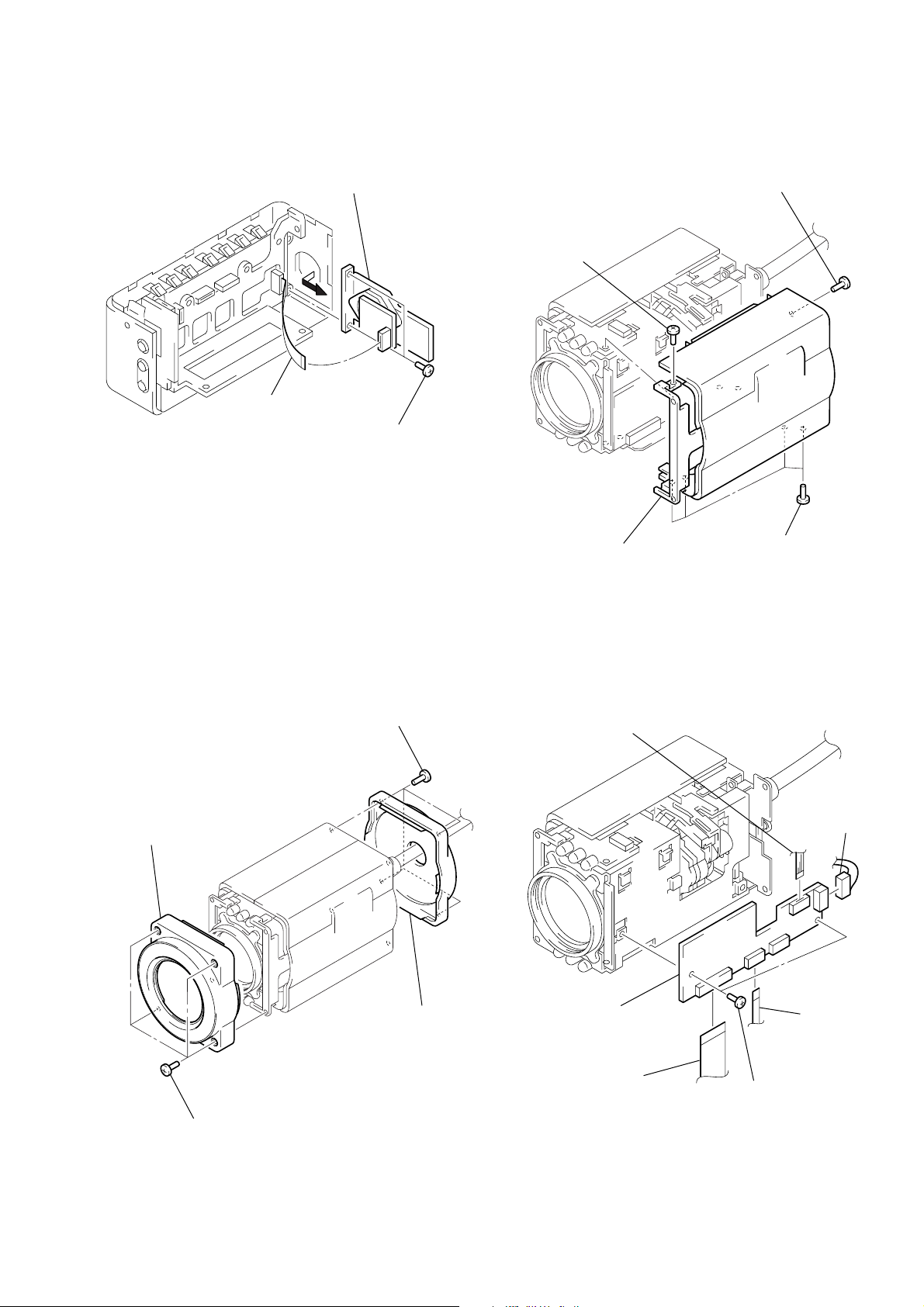
2-5. CN-116 BOARD 2-7. CABINET (R) ASS’Y
3 Four screws
(M2)
4 Cabinet (R) ass’y
2 Screw
(M2)
1 Screw
(M2)
3 CN-116 board
CN-116
1 Flat cable (FFC-274)
(CN990)
2 Two screws
2-6. CABINT (F/B) ASS’Y
2 Cabinet (F) ass’y
1 Four screws
(M2)
3 Four screws
(M2)
4 Cabinet (B) ass’y
2-8. IF-73 BOARD
1 Flexible board
(CN1801)
6 IF-73 board
4 Flat cable
(FFC-262)
(CN1802)
2 Connector
(CN1803)
IF-73 board
3 Flat cable
(FFC-280)
(CN1805)
5 Two screws
(M2)
2-3
Page 14
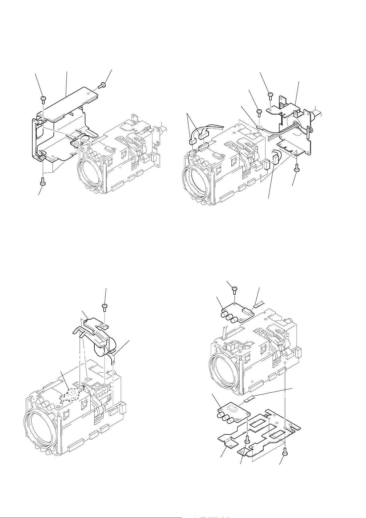
2-11. CONNECTION CORD2-9. CABINET (L) ASS’Y
1 Screw
(M2)
3 Three screws
4 Cabinet (L) ass’y
(M2)
IR-34
2 Screw
(M2)
IF-73 board
2 Two connectors
(CN301, 501)
IR-34
4 Lug
IF-73 board
6 Screw
3 Screw
(M2)
(M2)
1 Connector
(CN1803)
7 Connection cord
(BB bracket)
5 Two screws
(M2)
2-10. MOTOR (IR USE)
3 Motor (IR use)
Note: When installing
motor (IR use),
connect lever of
motor with IR lever.
IR lever
IR-34
IF-73 board
2 Screw
(M2)
1 Flexible board
(CN1801)
2-12. IR-34/35 BOARD
2 Screw
(M2)
3 IR-34 board
8 IR-35 board
1 Flat cable (FFC-264)
IR-34
IR-35
(CN090)
IF-73 board
6 Flat cable
(FFC-280)
(CN1090)
2-4
5 Tripod frame
7 Screw
(M2)
4 Three screws
(M2)
Page 15
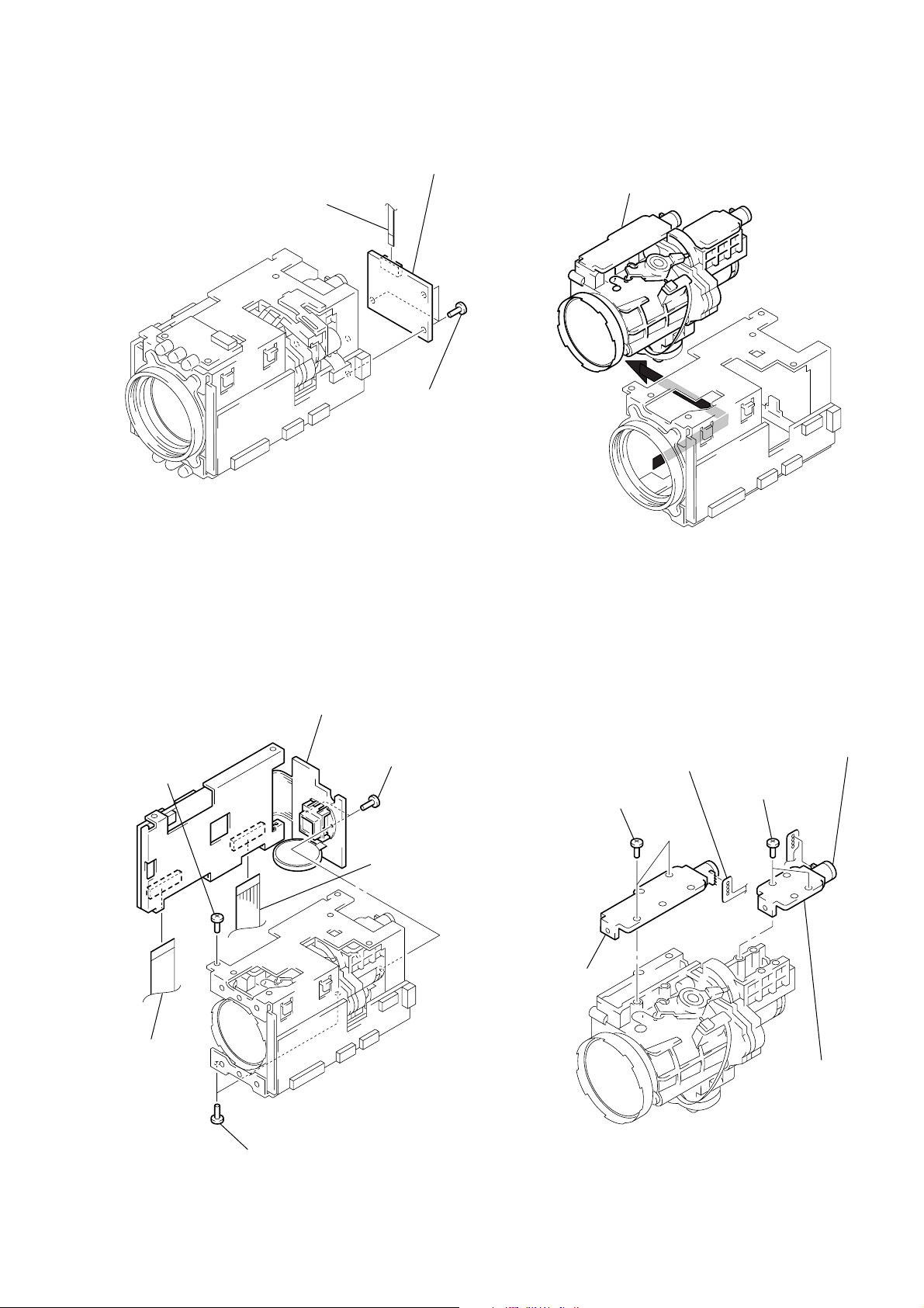
2-13. SE-93 BOARD 2-15. LENS DEVICE
6 Zoom stepping
motor
3 Focus stepping
motor
4 Two screws
(M1.7 × 3.5)
1 Break solders of
the flexible board
2 Two screws
(M1.7 × 3.5)
5 Break solders of
the flexible board
1 Flat cable (FFC-219)
(CN050)
IR-34
IF-73 board
3 SE-93 board
SE-93
2 Three screws
(M2)
1 Remove the lens device in the
direction of the arrow.
IF-73 board
2-14. VC-211 BOARD
2 Flat cable
4 Screw
(M2)
(CN703)
2-16. FOCUS/ZOOM STEPPING MOTOR
6 VC-211 board
5 Two screws
(B1.7 × 6)
VC-211
1 Flexible board
(CN401)
IF-73 board
3 Two screws
(M2)
Note: Flexible board of lens device is not supplied.
Please be careful not break the flexible board
when you change the motor unit.
2-5
Page 16
2-17. CIRCUIT BOARDS LOCATION
SW-328
(CONTROL SWITCH)
DT-106
MIC IN,
CONTROL SWITCH
CN-116
CAMERA CABLE
CONNECTOR
VW-1
(VIDEO WALKMAN CONNECTOR)
IR-34
(IR LIGHT)
VA-108
VIDEO/AUDIO OUTPUT,
CONTROL SWITCH
VC-211
CCD IMAGER, CAMERA Y/C PROCESS,
CAMERA CONTROL, MODE CONTROL
SE-93
(STEADY SHOT SENSOR)
IR-35
(IR LIGHT)
2-6
2-6 E
IF-73
(IR MOTOR DRIVE)
Page 17

3-1. OVERALL BLOCK DIAGRAM
CVX-V18NS/V18NSP
SECTION 3
BLOCK DIAGRAMS
IC401
IR-34 BOARD
IR-35 BOARD
D1090,1091,1092
M903
ZOOM
MOTOR
ZOOM
SENSOR
ZOOM
MOTOR
DRIVE
SE-93 BOARD
SE050
PITCH
SENSOR
SE051
YAW
SENSOR
D090,091,092
ZOOM LENS UNIT
ZOOM
LENS
M902
FOCUS
MOTOR
FOCUS
SENSOR
FOCUS
MOTOR
DRIVE
IC050
SENSOR
AMP
IR ON
IR ON
METER
IRIS
DRIVE
IRIS
HALL
SENSOR
HALL
AMP
IC402
M901
IR
MOTOR
MM M
VC-211 BOARD
IC001
CCD
IMAGER
CCD OUT
ZM RST SENS
HALL AD
IRIS COM
IRIS PWM
DIR0 A,B DIRI A,B
IF-73 BOARD
IC1801
IR MOTOR
DRIVE
V1-V4,VSHT
H1,H2,RG
IC102
S/H
AGC
FC RST SENS
IC1803
KEY SWITCH
CONTROL
A/D
CONV.
IC1802
IR MOTOR
PREDRIVER
KEY AD
IC101
TIMING
GENERATOR
10
IC203
ADJUST
VOLTAGE
CAMERA Y/C PROCESS
ZOOM/FOCUS
MOTOR CONTROL
8X2
DIGITAL
EFFECT
VC SO, VC SI, VC SCK
IC301
IC201
CHARACTER
GENERATOR
D/A
CONV.
IC202
2.0V
3.2V
15V
–7.0V
4.9V
EEPROM
Y OUT
C OUT
IC601
IC501
D/D
CONV.
IC302
75Ω
DRIVER
OSD SCK, OSD SO
IC602
CAMERA
CONTROL
UNREG
HI SO
HI SI
HI SCK
KEY AD
XRESET
INITIAL RESET
BACK UP VCC
IC703
D/D
CONV.
IC702
MODE
CONTROL
Y OUT
C OUT
BACK UP
VCC
IC701
KEY AD
CAMERA CABLE
CN-116 BOARD
Y OUT
C OUT
KEY AD KEY AD
SW-328 BOARD
INFINITY
MANU
AUTO
NIGHTSHOT
FAR
NEAR
POWER
T
ZOOM
W
FOCUS
DT-106 BOARD
MIC
PLUG IN
POWER
DISPLAY
DATE
TIME
Y OUT
C OUT
VA-108 BOARD
EXPOSURE
SHUTTER
TITLE
MENU
+
–
EXEC
IC841
AUDIO
AMP
AUDIO
5V
CAMERA
5V
IC821
Y/C MIX
75Ω
DRIVER
IC842
ALC AMP
IC843
D/D
CONV.
IC881
D/D
CONV.
UNREG
Q882
S-Y, S-C
AUDIO L, R
SWITCH
Y OUT
C OUT
VIDEO
AUDIO L
AUDIO R
VOLTAGE
S-TERMINAL
IC882
WATCH
VW-1 BOARD
VIDEO WALKMAN
CONNECTOR
IC883
VOLTAGE
WATCH
BATT(+)
BATT(–)
BATTERY
TERMINAL
05
3-1 3-2 3-3
Page 18

CVX-V18NS/V18NSP
3-2. CAMERA BLOCK DIAGRAM
VC-211 BOARD (1/3)
TO VIDEO OUT, AUDIO BLOCK
CN-116 BOARD CN991
(SEE PAGE 3-13)
IC001
CCD IMAGER
CCD OUT
VDD (+15V)
S_C OUT
S_Y OUT
SHT
IC102
S/H. AGC. A/D CONVERTER
PBL K
19
XSHP
(IC201)
X101
NTSC:28.6363
PAL:28.375
XCS TG
CK CONT
6dB
6dB
4.9V
21
XSHD
22
CLPDM
23
26
27
34
36
CAM DD ON
MUTE
S/H
S/H
CLP
CENTER
BIAS
WEN
FRQ
(IC301)
TO CAMERA CONTROL BLOCK(2/2)
CLAMP
MUTE
13
AMP
GCA
PB
35 30 29 4241
(SEE PAGE 3-12)
XVC SCK
VC SO
24
22
AGC
LINE
PB
S/H BLK
S/H
CAM
LINE
FLIP
AGC CONT 2
AGC CONT 1
Q302
B P F
DRV
REF SLOW ADCLK
44 16
(IC301)
L.P.F
FL301
Q301
A/D
CONVERTER
Q201
BUFFER
12
17
33
D9
43
I
11
D0
10
10
I
2
20
CLPOB
MCK
TO CAMERA
CONTROL BLOCK(1/2)
(SEE PAGE 3-9)
Q202
BUFFER
3.2V
(IC101)
XSG 1
XV 1
PB LK
VGAT
FSC
EN0
DIR0B
DIR0A
DIR1A
DIR1B
EN1
IRIS COM
FC RST
ZM RST
CL
MCK
ID
163
I
172
159
161
148
138
68
140
142
145
146
141
143
144
43
47
49
75
66
127
128
129
130
131
132
133
135
136
37
3
6
33
26
23
AD IN 10
I
AD IN 1
CLP1
ADCK
CCD CLKL
VCK
MCK
XSG 1
XV 1
ID
PB LK
VGAT
AHD
AVD
AMPO
OSCI
OSCO
BCK
OFSC
EN0
DIR0B
DIR0A
DIR1A
DIR1B
EN1
IRIS COM
FC RST
ZM RST
C IN
C OUT
Y OUT
IO Y
IO U
IO V
ENCODER
D/A CONY
7
V1
4
V2
3
2
V3
1
V4
RG
12
H2
14
H1
13
11
VL
10
8
Q001
BUFFER
V1
V2
V3
V4
RG
H2
H1
–7V
VSHT
15V
CN301
2
4
CCD OUT
–7V
15V
IC101
TIMING GENERATOR
10
3.2V
15V
–7V
H2
H1
RG
CLAMP
VDD1
13
VDD2
19
VDD3
20
VDD4
43
VDD6
24
XV HT
26
V1
25
V2
28
V3
31
V4
27
VH
29
VL
30
VM
22
H2
21
H1
18
RG
IC302
14 16
9
CLPDM
XSHP
XSHD
XRS
PB LK
XSG1
XV1
VGAT
WEN
CCDCKH
VCK
CLK 510
CK
OSCO
OSCI
DSGAT
AHD
AVD
SSK
SSI
SEN
RST
VSK
VSI
VEN
CKINH
6dB
6dB
1
15
16
17
2
32
48
ID
41
36
47
11
12
9
7
5
4
42
44
45
37
38
39
40
33
34
35
46
18
PB L K
XSG1
ID
XV1
V GAT
MCK
CL
XCS SYSTEM
XRST SYSTEM
26
31
10 27 30
FOCUS/ZOOM MOTOR CONTROL
CAM
SG
FOCUS/
ZOOM
MOTOR
CONTROL
A/D
D/A
D/A
YUV
XSCKSOSI
82 83 84 85 86
IC201
CAMERA Y/C PROCESS.
CAMERA
Y/C
PROCESS.
XCS
XRST
D/A
D/A
A/D
A/DAFT
MEM FLDI
DSD L ON
DSD R ON
DSD P ON
XSG V RST
ATF SAMPLE
MDCHA FLD
MECHA HD
MECHA VD
REC Y RF
REC C RF
Y RF IN
DOP IN
ATF IN
YMO1
YMO8
CMO1
CMO4
VI HDO
VI VDO
VI FLDO
YMI1
YMI4
CMI1
CMI4
MEM HDI
MEM VDI
CGCK
COLOR4
COLOR3
COLOR2
COLOR1
JOG VD
1/2 SWP
SWP DIR
SYS V
CK CONT
OSD SO
VIHDO
CL
XRST SYSTEM
XCS SYSTEM
SYS V
CL
CAM DD ON
TO CAMERA
CONTROL BLOCK (2/2)
(SEE PAGE 3-12)
15V
–7V
TBC VD
XTBC V RST
MEM VD
Q513
Q507,Q509,Q510,Q511
REG
IC301
D/A CONVERTER
HALL OFFSET
11
VCC
10
VDD
UNREG
2V
3.2V
4.9V
FB-3
FB-2
HALL GAIN
HALL REF
AGC CONT2
AGC CONT1
2
3
6
FRQ (X101)
18
7
FLIP
13
12
SI
17
16
SCK
15
DA STB
FRQ
FLIP
AGC CONT2
AGC CONT1
T501,Q501,D504
FB-4
FB-5
Q503,D502
REG
Q504,D503
REG
Q502,D501
REG
REG
(IC102)
OUT5
OUT4
OUT3
OUT2
IC501
64
57
DC/DC
CONTROL
56
50
TBC VD
XTBC V RESET
MEM VD
HALL GAIN
HALL OFFSET
HALL REF
SYS V
XCS SYSTEM
XRST SYSTEM
XCS TG
XVC SCK
VC SO
VC SI
MECHA VD
MECHA HD
MECHA FLD
XSG V RST
CK CONT
DA STB
SL SHUTTER WEWEN
CN501
UNREG
1
FB-5
14
FB-4
18
FB-2
38
FB-3
34
CONTROL BLOCK(1/2)
TO VIDEO OUT, AUDIO BLOCK
CN-116 BOARD CN991
(SEE PAGE 3-13)
TO CAMERA
(SEE PAGE 3-9, 10)
16
13
40
63
38
118
116
113
111
108
106
103
101
91
93
96
98
125
123
121
117
115
112
110
107
105
102
100
90
92
95
97
124
122
120
155
158
157
153
156
152
151
150
70
71
72
73
74
75
76
80
81
87
8
4
8
4
CONTROL BLOCK(2/2)
IC203
MEMORY
71
IY1
I
I
78
IY8
IC1
3
I
I
IC4
6
65
IHD
66
IVD
67
IFLD
30
OY1
I
I
23
OY8
15
DC1
I
I
12
DC4
16
OHD
17
OVD
15
OFLD
IC202
CHARACTER
GENERATOR
20
XHSYNC
19
XYSYNC
8
OSC
11
BLKC
13
BLKB
14
VC3
15
BLKA
16
VC2
17
VC1
18
VC0
TO CAMERA
(SEE PAGE 3-12)
RCK
WCK
TBC VD
VRSTL
SYSV
XRST
XCS
XSCK
CLK
XCS
DATA
XPCL
CL
50
MCK
52
36
54
55
53
45
46
SI
44
SO
43
XOSD SCK
1
XCS OSD
2
3
XSYS RST
4
XSYS RST
OSD SO
XCS OSD
XOSD SCK
XCS SYSTEM XRST SYSTEM
05
3-5 3-6 3-7 3-8
Page 19

3-3. CAMERA CONTROL (1/2) BLOCK DIAGRAM
CVX-V18NS/V18NSP
SE-93 BOARD
SE050
1
2
4
SE051
1
2
4
05
SENSOR AMP
4
8
16
12
IRIS
METER
M
H
ZOOM LENS
UNIT
ZOOM
SENSOR
FOCUS
SENSOR
M903
ZOOM
MOTOR
M
M902
FOCUS
MOTOR
M
IC050
20
2
19
18
3
6
4
5
TEMP COM
TEMP OUT
DRIVE (+)
DRIVE (–)
CONT (–)
CONT (+)
BIAS (+)
HALL (–)
HALL (+)
BIAS (–)
GND
SENSE VCC
ZM RST
FC RST
ZM XA
ZM A
ZM XB
ZM B
FC A
FC XA
FC B
FC XB
VC-211 BOARD (2/3)
CN601CN050
3.2V
3
PITCH AD
6
VST C RESET
4
YAW AD
5
22
23
20
18
21
19
17
12
10
11
16
13
15
14
8
7
5
6
1
4
2
3
9
CN401
Q552
DRIVE
Q553
ZM RST SENS
LENS RST LED
FC RST SENS
PLA/GLASS
3.2V
3.2V
22
20
10
26
24
IC402
IRIS DRIVE
–
8
+
IC402
HALL BIAS CONTROL
+
1
–
+
14
–
IC402
HALL GAIN CONTROL
IC401
B3
ZOOM
A3
8
MOTOR
B4
DRIVE
A4
A1
5
FOCUS
B1
MOTOR
A2
7
DRIVE
B2
VM2
VM1 VM33VC
4
(1/4)
(1/4)
(1/4)
IC602
CAMERA CONTROL
VDD3.2V
25
64
VDD
100
AVDD
AVRH
101
120
VDD
1
1
6
XTAL
2
EXTAL
7
XSYS RST
XCS VC
77
HI SO
76
HI SI
75
HI SCK
74
SYS V
108
43
LENS FILTER ON SW
LENS RST LED
22
VST C CHAGE
85
23
ZM RST SENS
YAW AD
98
PITCH AD
97
70
IRIS PWM
LENS TEMP AD
86
93
HALL AD
FC RST SENS
24
94
PLA/GLASS
XCS SYSTEM
19
80
VC SI
79
VC SO
78
XVC SCK
XTBC V RESET
107
XRST SYSTEM
119
16
XCS IO
MECHA VD
118
113
TBC VD
112
MECHA HD
MECHA FLD
111
MEM VDI
114
CK CONT
18
XSG V RST
45
XCS TG
84
DA STB
21
XCS EEPROM
27
XWE EEPROM
26
SL SHUTTER WE
51
9
PDR CS
VC SO
XVC SCK
XRST SYSTEM
MEM VDI
TO CAMERA
CONTROL
BLOCK(2/2)
(SEE PAGE
3-12)
X401
20MHz
XSYS RST
VC SI
VC SO
SYS V
TBC VD
DA STB
XCS TG
XCS VC
HI SO
HI SI
HI SCK
SYS V
VST C RESET
MEM VDI
XCS
DO
4
DI
3
RST
XSCK
2
VCC 3.2V
8
IC601
EEPROM
TO CAMERA
CONTROL BLOCK(2/2)
(SEE PAGE 3-12)
LENS TEMP AD
9
10
3
2
EN4
EN3
EN2
EN1
HALL GAIN
HALL OFFSET
HALL REF
19
18
IN4
17
16
IN3
15
14
IN2
13
12
IN
12
13
1123
3.2V
4.9V
5
6
LPF
IC402
HALL ANP
+
–
IRIS PWM
LENS FILTER ON SW
(1/4)
HALL AD
7
HALL GAIN
HALL OFFSET
HALL REF
ZM RST
FC RST
IRIS COM
EN1
DIR1B
DIR1A
EN0
DIR0B
DIR0A
TO CAMERA BLOCK
(SEE PAGE 3-6, 8)
TO CAMERA BLOCK
(SEE PAGE 3-8)
XVC SCK
XCS SYSTEM
XTBC-V RESET
XRST SYSTEM
MECHA VD
MECHA HD
MECHA FLD
CK CONT
XSG V RST
MEM VDI
SL SHUTTER WE
3-9 3-10
Page 20

CVX-V18NS/V18NSP
3-4. CAMERA CONTROL (2/2) BLOCK DIAGRAM
IF-73 BOARD VC-211 BOARD (3/3)
E3.2V
CN1803
CAMERA BLOCK
CN-116 BOARD
CN991
(SEE PAGE 3-13)
M901
IR
M
MOTOR
KEY AD3
KEY AD4
KEY AD5
2A
-2A
-2B
2B
1
2
3
4
CN1801
3
4
5
6
KEY AD3
KEY AD4
KEY AD5
KEY AD6
22
10
20
MOTOR DRIVER
2A
8
2A
2B
2B
IC1801
VM
IN3
EN3
IN4
EN4
4
11
23
VC
3
16
17
18
19
30
31
32
33
4.9V
3.2V
IC1803
VISCA CONTROL
KEY AD3
KEY AD4
KEY AD5
KEY AD6
IC1802
MOTOR PRE DRIVER
15
DIR2A
17
EN2
16
DIR2B
WAKE UP
VDD
VD IN
CS
SCK
SIN
CKIN
X CLR
VCC
RESET
SCK
TITLE
DOWN
MENU
20
1
3
4
5
8
9
SI
SO
CS
UP
5
6
8
29
47
1
9
10
11
18
39
25
28
27
26
3.2V
E3.2V E3.2V
IC804
REGULATOR
VOUT VIN
1 3
UNREG
3.2V
4.9V
XVISCA RESET
SCK2
SO2
SI2
CS2
XWAKE UP
MEM VD
PDR CS
XVC SCK
VC SO
XRST SYSTEM
CL
30
20
19
13
18
17
16
15
14
24 7
8
7
11
12
10
9
CN703CN1802
1
11
12
18
13
14
15
16
17
23
24
20
19
21
22
UNREG
3.2V
4.9V
XVISCA RESET
SCK2
SO2
SI2
CS2
XWAKE UP
KEY AD3
CL
MEM VD
PDR CS
XVC SCK
VC SO
XRST
SYSTEM
X701
20MHz
X702
32.768kHz
TO CAMERA BLOCK
(SEE PAGE 3-7)
TO CAMERA
CONTROL
BLOCK(1/2)
(SEE PAGE
3-10)
20MHz OUT
40
20MHz IN
41
32kHz IN
52
32kHz OUT
53
5
RESET
50
SCK2
SO2
49
48
SI2
CS2
47
WAKE UP
21
96
KEY AD3
IC702
MODE CONTROL
ACV SENSE
XSYS RST
XOSD SCK
CAM DD ON
VTR DD ON
LANC OUT
VDD
XRESET
BATT IN
XCS VC
HI SI
HI SO
XHI SCK
SYS V
XCS OSD
OSD SO
LANC IN
IC701
INITIAL RESET
V OUT
6
5
RESET
4
CS
BACKUP VCC
V BAT
XSYS RST
XCS VC
HI SI
HI SO
XHI SCK
SYS V
XSYS RST
XCS OSD
OSD SO
XOSD SCK
CAM DD ON
CAM DD ON
VTR DD ON
3.2V
UNREG
V IN
7
3
CN704 LANC
D704
2 3
BT701
TO CAMERA
CONTROL BLOCK(1/2)
(SEE PAGE 3-10)
TO CAMERA BLOCK
(SEE PAGE 3-6, 7)
TO POWER(CAMERA) BLOCK
(SEE PAGE 3-17)
1
3.2V
UNREG
2
3
4
LANC OUT
LANC IN
TO LANC JIG
V OUT
IC703
REGULATOR
D701
UNREG
V IN
42
51
75
76
77
86
87
38
61
91
9
22
33
34
35
64
44
45
46
28
29
2
1
IR-34 BOARD
4.9V
CN502
1
1
2
2
3
3
D091
IR-35 BOARD
D1091
D1092
Q1091
05
D1090
Q1090
CN1090
D090 D092
43
CN1805
1
1
2
2
3
3
4
4
4.9V
4.9V
IR_ON
1
20
4.9V
2
29
IR ON
4
4
CN090
Q090
Q091
3-11 3-12
Page 21

3-5. VIDEO OUT, AUDIO BLOCK DIAGRAM
CVX-V18NS/V18NSP
TO CAMERA BLOCK
VC-211 BOARD CN501
(SEE PAGE 3-8)
TO CAMERA BLOCK
VC-211 BOARD CN301
(SEE PAGE 3-5)
TO CAMER CONTRL BLOCK (2/2)
IF-73 BOARD CN1805
(SEE PAGE 3-11)
UNREG
S-Y_OUT
S-C_OUT
KEY_AD3
KEY_AD4
KEY_AD5
CN-116 BOARD
CN991
1
4
6
7
8
10
CN990 CN883
UNREG
14
UNREG
13
S-Y_OUT
10
S-C_OUT
8
KEY_AD3
6
KEY_AD4
5
KEY_AD5
4
VA-108 BOARD
1
2
S-Y_IN
5
S-C_IN
7
9
10
11
UNREG
KEY_AD5
KEY_AD4
18
16
MENU
IC821
Y/C MIX VIDEO AMP
6dB
6dB
1211
TITLE
+
EXPOSURE
CN884
KEY_AD3
KEY_AD4
J821
43
J823
1
2
1
S VIDEO
2
VIDEO
DT-106 BORAD (2/2)
CN996
KEY_AD3 KEY_AD3
10
KEY_AD4
9
DATE
TIME
DISPLAY
CN997
KEY_AD4
4
5
SW-328 BOARD
CN941
KEY_AD3
3
W
KEY_AD4
2
NIGHTSHOT
T
NEAR
ON
OFF
FAR
FOCUS
INFINITY
MANU
AUTO
9
14
6dB6dB
6
SHUTTER
–
EXEC
MIC
PLUG IN
POWER
DT-106 BOARD (1/2)
J995
MIC_R
MIC_L
05
CN996 CN884
3
2
8
9
R
AUDIO
L
VW-1 BOARD
CN901
CAM_Y
6
CAM_C
8
AUDIO_L
10
AUDIO_R
11
CN902
CAM_Y
CAM_C
AUDIO L
AUDIO R
3
20
VIDEO WALKMAN
CONNECTOR
6
5
Q821
BUFFER
Q822
BUFFER
AMP
AMP
IC842
ALC AMP
LEVEL
DETECT
7
1
IC841
AMP
BUFFER
5
3
BUFFER
7 9
1 13
CN882
CAM_Y
CAM_C
AUDIO_L
AUDIO_R
11
9
7
6
J823
3-13 3-14
Page 22

CVX-V18NS/V18NSP
3-6. POWER (MAIN UNIT) BLOCK DIAGRAM
VIDEO WALKMAN
CONNECTOR
BATTERY
TERMINAL
VW-1 BOARD
18
19
2
4
9
10
12
13
7
VA-108 BOARD
CN881
BATT (+)
1
2
BATT SW (-)
3
BATT (-)
4
5
CN901CN902
CN882
UNREG
16
1
UNREG
15
2
UNREG GND
14
3
UNREG GND
13
4
GND
12
5
GND
10
7
GND
5
12
16
9
GND
1
GND
8
F881
1.25A
Q841
BUFFER
5.5V DETECT
2
VDD OUT
4.7V DETECT
2
VDD
IC883
IC884
OUT
IC841
MIC AMP
1
1
Q882
SWITCH
Q881
SWITCH
8 5
IC842
ALC
VCCVCC
Q884
SWITCH
IC881
VOLTAGE REGURATOR
IC843
VOUT
VOUT
1
1
3
VIN
VOLTAGE REGURATOR
3
VIN
Q883
SWITCH
Q821
BUFFER
Q822
BUFFER
IC821
Y/C MIX VIDEO AMP
VCC2
10
27
VCC1
30
VCC3
CN883
UNREG
UNREG
GND
GND
Y_GND
C_GND
GND
GND
CN884
BATT LED
POWER(1)
POWER(2)
GND
AU_GND
1
2
3
4
6
8
13
14
3
4
5
5V
6
7
10
CN-116 BOARD
CN990
UNREG
14
UNREG
13
GND
12
GND
11
Y_GND
9
C_GND
7
GND
2
GND
1
CN996
BATT LED
8
POWER(1)
7
POWER(2)
6
5V
5
GND
4
AU_GND
1
D995
BATT
LED
CN995
POWER(1)
POWER(2)
GND
CN991
TO POWER (CAMERA)
POWER(1)
POWER(2)
5V
GND
UNREG
GND
Y_GND
C_GND
GND
VC-211 BOARD CN501
(SEE PAGE 3-17)
TO POWER (CAMERA)
VC-211 BOARD CN301
(SEE PAGE 3-17)
TO POWER (CAMERA)
IF-73 BOARD CN1803
(SEE PAGE 3-20)
S948
POWER
ON
OFF
D941
POWER
LED
1
2
3
5
9
CN941
1
2
5V
3
6
6
5
4
1
DT-106 BOARD
AU_GND
05
SW-328 BOARD
3-15 3-16
Page 23

3-7. POWER (CAMERA) BLOCK DIAGRAM
CVX-V18NS/V18NSP
TO POWER (MAIN UNIT)
CN-116 BOARD CN991
(SEE PAGE 3-16)
TO POWER (MAIN UNIT)
CN-116 BOARD CN991
(SEE PAGE 3-16)
UNREG
GND
Y_GND
C_GND
VC-211 BOARD
CN501
UNREG
1
2
CN301
3
5
CN704
UNREG
2
4.9V
4.9V
4.9V
4.9V
4.9V
1
1
11
12
30
1
2
3
TO LANC JIG
IF-73 BOARD
CN1802CN703
UNREG
30
3.2V
20
4.9V
19
4.9V
1
F.B.
3
IC1804
3.2V REG
V IN
20
V OUT
IC1802
PRE DRIVER
VCC
1
PULL UP
RESISTANCE
F.B.
IC1803
VISCA COM
8
VCC
29
AVCC
47
VCC
NS MOTOR DRIVER
3
4
11
23
IC1801
VCC
VM1
VM3
VM2
CN1803
CN1805
4.9V
4.9V
4.9V
33
5
1
2
3
GND
SE-93 BOARD
CN050
3.2V3.2V
TO POWER (MAIN UNIT)
CN-116 BOARD CN991
(SEE PAGE 3-16)
IR-35 BOARD
CN1090
4.9V
1
4.9V
2
4.9V
3
IR-34 BOARD
CN090
4.9V
1
4.9V
2
4.9V
3
PITCH SENSOR
Q1090
SWITCH
Q090
SWITCH
SE050
Q1091
SWITCH
Q091
SWITCH
IC050
SENSOR AMP
20
VCC
SE051
YAW SENSOR
11
3.2V
IC701
Q513
7
3
Q508
RESET
VIN
VOUT
VBAT
6
2V
3.2V
–7V
+15V
CAM_DD_ON
4.9V
VTR_DD_ON
SW_UNREG
2V
IC703
REGURATOR
VIN
2
VOUT
3.2V
2
6
4
5
3
D504
D704
Q507,Q509
Q510,Q511
–7.0V REG
EMERGENCY
BT701
DETECT
D701
L501
CHOKE
IC501
DD CONV
Q503
VREF
SWITCHING
Q504
SWITCHING
Q501
SWITCHING
Q502
SWITCHING
D502
CHOKE
D503
SWITCHING
3
1
L503
CHOKE
L504
Q506
T501
28
VCC
22
CT
FB-5
FB-4
COMP
FB-3
FB-2
STC BY
VREF
64
14
57
60
18
63
51
43
13
56
34
50
38
29
30
27
21
RT
OUTPUT-5
OUTPUT-4
MOSGATE-4
OUTPUTVCC-56
OUTPUTVCC-24
OUTPUTVCC-13
OUTPUT-3
OUTPUT-2
STD BY3
42
51
77
86
87
28
29
IC702
HI-COM
VDD
VDD
AVDD
VDD
VDD
CAM_DD ON
VTR_DD_ON
TIMING GENERATOR
S/H AGC A/D
IC101
VDD1
VDD2
VDD3
VDD4
VDD6
29
VL
VH
27
IC001
CCD IMAGER
11
VL
8
VDD
IC102
DRVDD
DVDD
ACVCC
ADVDD
10
13
19
20
43
3.2V
IC202
CHARACTER GENERATOR
12
17
33
43
F.B.
3.2V
3.2V
2V
IC401
ZOOM/FOCUS DRIVE
VM1
3
VCC
VM3
VM2
IC402
IRIS DRIVE
F.B.
4
11
23
ZOOM/FOCUS MOTOR CONTROL
58
77
94
114
137
147
162
4.9V
Q401
SENSOR
POWER SUPPLY
IC203
MEMORY
VDD DRAM
VDD LOGIC
VDD LOGIC
VDD LOGIC
VDD LOGIC
IC201
CAMERA Y/C PROCESS
DVDD1
DVDD2
DVDD3
DVDD4
DVDD5
DVDD6
DVDD7
VDD IO
ADVD2
VDD IO
ADVD3
ADVD4
AVDD
AVDD
AVDD
AVDD
AVDD
AVDD
AVDD
AVDD
AVDD
PLL_VDD
EVR_VDD
AVDD
IO_VDD1
IO_VDD2
IO_VDD3
IO_VDD4
10
19
20
29
30
41
42
50
52
175
176
67
104
119
154
3.2V
F.B.
5
VDD
IC301
D/A CONVERTER
10
VDD
11
VCC
Q301
BUFFER
Q302
BUFFER
IC302
Y/C MIX VIDEO AMP
10
VCC2
27
VCC1
30
VCC3
F.B.
Q201
BUFFER
Q202
BUFFER
F.B.
3.2V
2V
3.2V
3.2V
3.2V
3.2V
EEPROM
8
IC601
VCC
3.2V
4.9V
25
64
100
120
IC602
CAMERA MICOM
VDD
VDD
AVDD
VDD
8
19
32
37
38
64
7
31
51
68
9
UNREG
3.2V
CN502
CN601
3.2V
05
3-17 3-18 3-19
4
VCC
CN401
IRIS DRIVE+
8
ZOOM
LENS UNIT
3-20 E
Page 24

SECTION 4
SCHEMATIC DIAGRAMS
4-1. FRAME (1/2) SCHEMATIC DIAGRAM
1 2 3 4 5 6 7 8 9 10 11 12
CVX-V18NS/V18NSP
D
A
B
C
E
F
M901
IR
MOTOR
8765432
CN1801 8P
2B
NC
NC
–2B
IF-73 BOARD
–2A
CONNECTION
CORD
1
CN501 2P
UNREG
2
UNREG_GND
12345
CN301 6P
S_GND
S_C_OUT
Y_GND
S_Y _OUT
6
GND
VIDEO_OUT
VC-211 BOARD
CN401 23P
TEMP
TEMP
ZM
GND
FC_RST
SENSE
PLA/GLASS
FC_A
FC_B
FC_XB
FC_XA
ZM_A
ZM_B
ZM_XB
ZM_XA
DRIVE(+)
DRIVE(–)
CONT(+)
CONT(–)
HALL(–)
BIAS(–)
HALL(+)
BIAS(+)
CN601 6P
GND
GND
3.2V
VST_C_RESET
YAW_AD
PITCH_AD
23
22
21
20
19
18
17
16
15
14
13
12
11
10
9
8
7
6
5
4
3
2
1
1
2
3
4
5
6
FFC-219
1
2
3
4
5
6
LENS UNIT
CN050 6P
GND
GND
3.2V
VST_C_RESET
YAW_AD
PITCH_AD
1
2A
NC
NC
12345
CN1803 5P
KEY_AD3
KEY_AD4
KEY_AD5
KEY_AD6
GND
UNREG
GND
GND
KEY_AD6
KEY_AD5
KEY_AD4
KEY_AD3
KEY_AD2
KEY_AD1
KEY_AD0
3.2V
4.9V
SCK2
SO2
SI2
CS2
XWAKE_UP
XVISCA_RESET
VC_SO/EN2
XVC_SCK/DIR_2B
CL/DIR_2A
XRST_TANUKI
MEMVD
PDR_CS
O_ZOOM
D_ZOOM
N.C.
N.C.
IR_ON
D4.9V
30
29
28
27
26
25
24
23
22
21
20
19
18
17
16
15
14
13
12
11
10
9
8
7
6
5
4
3
2
1
FFC-262
CN703 30PCN1802 30P
1
2
3
4
5
6
7
8
9
10
11
12
13
14
15
16
17
18
19
20
21
22
23
24
25
26
27
28
29
30
UNREG
GND
GND
KEY_AD6
KEY_AD5
KEY_AD4
KEY_AD3
KEY_AD2
KEY_AD1
KEY_AD0
3.2V
4.9V
SCK2
SO2
SI2
CS2
XWAKE_UP
XVISCA_RESET
VC_SO/EN
XVC_SCK/DIR_0B
CL/DIR_0A
XRST_TANUKI
MEMVD
PDR_CS
O_ZOOM
D_ZOOM
N.C.
N.C.
IR_ON
D4.9V
CN-116 BOARD
CN991
(SEE PAGE 4-4)
ZOOM
SE-93 BOARD
G
H
GND
GND
GND
IR_ON
7654321
7654321
CN1090 7P CN1805 7P
GND
GND
GND
IR_ON
4.9V
4.9V
4.9V
4.9V
GND
7654321
7654321
CN090 7P CN502 7P
GND
GND
FFC-264FFC-280
GND
GND
GND
IR_ON
IR_ON
4.9V
4.9V
4.9V
4.9V
4.9V
4.9V
GND
GND
CN704 6P
65432
LANC_IN
TO
LANC JIG
3.2V
UNREG
LANC_OUT
1
4.9V
4.9V
I
IR-35 BOARD IR-34 BOARD
J
05
FRAME (1/2)
4-1 4-2
Page 25

CVX-V18NS/V18NSP
4-2. FRAME (2/2) SCHEMATIC DIAGRAM
1 2 3 4 5 6 7 8 9 10 11
VIDEO WALKMAN CONNECTOR
D
G
A
POWER
ON
OFF
B
NIGHTSHOT
OFF
ON
123456789
CN902 20P
Y_OUT
AUDIO_L_IN
(VIDEO_OUT)
AUDIO_R_IN
VIDEO_IN_GND
(VIDEO_OUT_GND)
1011121314151617181920
ID1
IO_GND
ADI_GND
LANC_GND
ADI_GND
LANC_SIG
AUDIO_IN_GND
VW-1 BOARD
ID2
(AUDIO_L_OUT)
(AUDIO_R_OUT)
(AUDIO_OUT_GND)
C_OUT
ADI_UNREG
ADI_UNREG
SW-328 BOARD
ID1
T
C
ZOOM
W
FAR
NEAR
FOCUS
INFINITY
MANU
AUTO
5V
GND
KEY_AD4
KEY_AD3
12345
POWER(2)
POWER(1)
6
UNREG
CN901 16PCN882 16P
123456789
16151413121110
UNREG
UNREG
UNREG_GND
UNREG
UNREG_GND
GND
CAM_Y
UNREG_GND
FFC-275
GND
CAM_Y
UNREG_GND
GND
GND
CAM_C
AUDIO_L
10111213141516
987654321
GND
GND
CAM_C
AUDIO_L
FFC-272
E
65432
CN997 6P CN941 6P
BATT
F
MIC
PLUG IN
POWER
DISPLAY
DATE
TIME
DT-106 BOARD
GND
KEY_AD4
5V
KEY_AD3
1
POWER(2)
POWER(1)
CN996 10P
KEY_AD3
KEY_AD4
BATT_LED
POWER(1)
POWER(2)
5V
GND
MIC_R
MIC_L
AU_GND
10
9
8
7
6
5
4
3
2
1
FFC-273
1
2
3
4
5
6
7
8
9
10
CN884 10P
KEY_AD3
KEY_AD4
BATT_LED
POWER(1)
POWER(2)
5V
GND
MIC_R
MIC_L
AU_GND
EXPOSURE
SHUTTER
TITLE
MENU
EXEC
VA-108 BOARD
S VIDEO
OUT PUT
+
–
AUDIO_R
AUDIO_R
VIDEO
L
R
GND
GND
ID1
AUDIO
ID2
ID2
LANC
LANC
GND
GND
CN883 14P
UNREG
UNREG
GND
GND
S_Y_IN
Y_GND
S_C_IN
C_GND
KEY_AD3
KEY_AD4
KEY_AD5
KEY_AD6
GND
GND
CN881 5P
BATT_(+)
BATT_SW(+)
BATT_SW(–)
BATT_(–)
BATT_SIG
1
2
3
4
5
6
7
8
9
10
11
12
13
14
1
2
3
4
5
FFC-274
CN-116 BOARD
CN990 14P
9
8
7
6
5
4
3
2
1
TERMINAL
UNREG
UNREG
GND
GND
S_Y_IN
Y_GND
S_C_IN
C_GND
KEY_AD3
KEY_AD4
KEY_AD5
KEY_AD6
GND
GND
BATTERY
14
13
12
11
10
CN991 12P
UNREG
UNREG_GND
Y_GND
S-Y_OUT
C_GND
S_C_OUT
KEY_AD3
KEY_AD4
GND
KEY_AD5
KEY_AD6
NC
1
2
3
4
5
6
7
8
9
10
11
12
TO
CONNECTION CORD
(SEE PAGE 4-2)
FRAME (2/2)
H
05
4-3 4-4 E
Page 26

CVX-V18NS/V18NSP
SECTION 5
ADJUSTMENTS
NTSC model : CVX-V18NS
PAL model : CVX-V18NSP
5-1. PREPARATIONS BEFORE ADJUSTMENT
5-1-1. List of Service Tools
• Oscilloscope • Regulated power supply • Vectorscope • Frequency counter
• Color monitor • Digital voltmeter
Ref. No.
Filter for color temperature correction (C14)
J-1
ND filter 1.0
J-2
ND filter 0.3
Pattern box PTB-450
J-3
Color chart for pattern box
J-4
Adjusting remote commander
J-5
(RM-95 upgraded). Note
Clear chart for pattern box
J-6
CPC jig
J-7
Siemens star
J-8
Mini pattern box
J-9
Note: If the microprocessor IC in the adjusting remote commander is not the new microprocessor (UPD7503G-C56-12), the pages
cannot be switched.
In this case, replace with the new microprocessor (8-759-148-35).
J-1 J-2
Name
J-3
Parts Code
J-6080-058-A
J-6080-808-A
J-6080-818-A
J-6082-200-A
J-6020-250-A
J-6082-053-B
J-6080-621-A
J-649-193-0A
J-6080-875-A
J-6082-353-B
Usage
Auto white balance adjustment/check
White balance adjustment/check
White balance check
White balance check
Flange back check
Flange back Adjustment
J-4 J-5
J-6
J-7
J-8 J-9
Fig. 5-1-1
5-1
Page 27

5-1-2. Preparations
l
Note 1: For details of how remove the cabinet and boards, refer
to “2. DISASSEMBLY”.
1) Connect the equipment for adjustments according to Fig. 5-1-3.
2) Connect the adjusting remote commander to the CN704 on
the VC-211 board via CPC jig (J-649-193-0A).
Pattern box
L
Front side of the lens
L = About 40 cm
Fig. 5-1-2
Regulated power supply
(7.2
±
0.1 Vdc)
Main unit
CN704
Video/Audio
output terminal
Camera
VC-211
board
CPC jig
(J-649-193-0A)
Audio (L)
Audio (R)
Video
Adjusting remote comander
(J-6082-053-B)
color minitor vectorscope
Ω
75
termina
Fig. 5-1-3
5-2
Page 28

5-1-3. Precautions
1. Setting the Switch
Unless otherwise specified, set the switches as follows and perform adjustments.
1. POWER switch (Main unit) ................................ON
2. NIGHT SHOT switch (Main unit) ...................... OFF
3. FOCUS switch (Main unit) .................................AUTO
2. Order of Adjustments
Basically carry out adjustments in the order given.
Color bar chart standard picture frame
H
Yellow
AB B
Cyan
Green
A=B
White
Magenta
Red
Blue
A
Enlargement
0
±
0.1msec
V
Fig. a (Video output terminal
output waveform)
Difference in level
B
A
Fig. 5-1-4
3. Subjects
1) Color bar chart (Standard picture frame).
When performing adjustments using the color bar chart, adjust the picture frame as shown in Fig. 5-1-4. (Standard picture frame)
2) Clear chart (Standard picture frame)
Remove the color bar chart from the pattern box and insert a
clear chart in its place. (Do not perform zoom operations during this time.)
3) Chart for flange back adjustment
Join together a piece of white A0 size paper (1189mm × 841
mm) and a piece of black paper to make the chart shown in
Fig. 5-1-5.
Note: Use a non-reflecting and non-glazing vellum paper. The
size must be A0 or larger and the joint between the white
and black paper must not have any undulations.
Electronic beam scanning frame
Red
Cyan
White
Green
Yellow
Blue
Magenta
CRT picture frame
Fig. b (TV monitor picture)
Direct the camera toward the subject and place the
subject with the distance (about 40 cm) from camera
until the specified picture frame fills the monitor display as shown in Fig. a and Fig. b.
White
Black
841mm
5-3
1189mm
Fig. 5-1-5
Page 29

5-1-4. Adjusting Remote Commander
The adjusting remote commander is used for changing the calculation coefficient in signal processing, EVR data, etc. The adjusting remote commander performs bi-directional communication
with the unit using the remote commander signal line (LANC).
The resultant data of this bi-directional communication is written
in the non-volatile memory.
1. Used Adjusting Remote Commander
1) Connect the adjusting remote commander to the CN704 on
the VC-211 board via CPC jig (J-649-193-0A).
2) Adjust the HOLD switch of the adjusting remote commander
to “HOLD” (SERVICE position).
3) Turn on the power with the POWER switch of the unit.
If it has been properly connected, the LCD on the adjusting remote commander will display as shown in Fig. 5-1-6.
0 : 00 : 00
Page Data Address
• Changing the address
The address increases when the FF ()) button is pressed,
and decreases when the REW (0) button is pressed. There
are altogether 256 addresses, from 00 to FF.
• Changing the data (Data setting)
The data increases when the PLAY (() button is pressed,
and decreases when the STOP (p) button is pressed. There
are altogether 256 data, from 00 to FF.
• Writing the adjustment data
The PAUSE button must be pressed to write the adjustment
data in the nonvolatile memory. (The new adjustment data
will not be recorded in the nonvolatile memory if this step is
not performed)
2. Precautions Upon Using the Adjusting Remote
Commander
Mishandling of the adjusting remote commander may erase the
correct adjustment data at times. T o prev ent this, it is recommended
that all adjustment data be noted down before beginning adjustments and new adjustment data after each adjustment.
Fig. 5-1-6
4) Operate the adjusting remote commander as follows.
• Changing the page
The page increases when the EDIT SEARCH + button is
pressed, and decreases when the EDIT SEARCH – button is
pressed. There are altogether 16 pages, from 0 to F.
Hexadecimal
notation
LCD Display 0123456789AbcdEF
Decimal notation
conversion value
0123456789ABCDEF
01234567891011
12 13 14 15
Table 5-1-1
5-4
Page 30

5-1-5. Data Processing
The calculation of the DDS display and adjusting remote commander display data (hexadecimal notation) are required for obtaining the adjustment data of some adjustment items. In this case,
after converting the hexadecimal notation to decimal notation,
calculate and convert the result to hexadecimal notation, and use
it as the adjustment data. Table 5-1-2. indicates the hexadecimal
notation- the decimal notation, calculation table.
Hexadecimal nontation-Decimal notation
The lower digits of the 0 1 2 3 4 5 6 7 8 9 A B C D E F
hexadecimal notation
The upper digits of the (A)(b)(c)(d)(E)(F)
hexadecimal notation
0 0 1 2 3 4 5 6 7 8 9 101112131415
1 16 17 18 19 20 21 22 23 24 25 26 27 28 29 30 31
2 32 33 34 35 36 37 38 39 40 41 42 43 44 45 46 47
3 48 49 50 51 52 53 54 55 56 57 58 59 60 61 62 63
4 64 65 66 67 68 69 70 71 72 73 74 75 76 77 78 79
5 80 81 82 83 84 85 86 87 88 89 90 91 92 93 94 95
6 96 97 98 99 100 101 102 103 104 105 106 107 108 109 110 111
7 112 113 114 115 116 117 118 119 120 121 122 123 124 125 126 127
8 128 129 130 131 132 133 134 135 136 137 138 139 140 141 142 143
9 144 145 146 147 148 149 150 151 152 153 154 155 156 157 158 159
A (A) 160 161 162 163 164 165 166 167 168 169 170 171 172 173 174 175
1→
B (b) 176 177 178 179 180 181 182 183 184 185 186 187 188 189 190 191
C (c) 192 193 194 195 196 197 198 199 200 201 202 203 204 205 206 207
D (d) 208 209 210 211 212 213 214 215 216 217 218 219 220 221 222 223
E (E) 224 225 226 227 228 229 230 231 232 233 234 235 236 237 238 239
F (F) 240 241 242 243 244 245 246 247 248 249 250 251 252 253 254 255
Note : ( ) indicate the adjusting remote control unit display.
2
↓
(Example) In the case that the adjusting remote control unit display are BD (bd).
As the upper digit of the hexadecimal notation is B (b), and the lower digit is D (d), the intersection “189” of the
1 and 2 in the above table is the decimal notation to be calculated.
Table 5-1-2
5-1-6. Adjusting Items when Replacing a Board or Main Parts
When replacing a board or main parts, adjust the items indicated by r in the following table.
Replaced parts
Adjustment
Lens device
VC-211 board VA-108 board IC001
(COMPLETE) (COMPLETE) (CCD BLOCK ASSY)
Y OUT level adj. rr
C OUT level adj. rr
28 MHz origin oscillation adj. r
Lens type adj. rr
HALL adj. rr
Flange back adj. rr r
Color reproduction adj. rr
IRIS IN/OUT adj. rr r
Auto white balance standard data input rr
Auto white balance adj. rr
5-5
Page 31

5-2. INITIALIZATION OF D, E, F PAGE DATA
1. Initializing D, E, F Page Data
Note 1: If “Initializing D, E, F Page Data” is performed, all data
of the D page, E page and F page will be initialized.
Note 2: If the D, E, F page data has been initialized, “Modifica-
tion of D, E, F page Data” and all adjustments need to be
performed again.
Adjustment Page D
Adjustment Address 00 to FF
Adjustment Page E
Adjustment Address 00 to FF
Adjustment Page F
Adjustment Address 10 to FF
Initializing Method:
1) Select page: 0, address: 01, and set data: 01.
2) Select page: 2, address: 00, set data: 55 (NTSC) or data: 51
(PAL), and press the PAUSE button of the adjusting remote
commander.
3) Select page: 2, address: 01, set data: 55 (NTSC) or data: 51
(PAL), and press the PAUSE button of the adjusting remote
commander.
4) Select page: 2, address: 02, and check that the data is “01”.
5) Select page: 3, address: 00, set data: 29, and press the PAUSE
button of the adjusting remote commander.
6) Select page: 3, address: 01, set data: 29, and press the PAUSE
button of the adjusting remote commander.
7) Select page: 0, address: 01, and set data: 00.
8) Perform “Modification of D, E, F Page Data”.
2. Modification of D, E, F Page Data
If D, E, F PAGE data has been initialized, change the data of the
“Fixed data-2” address shown in the following tables by manual
input.
Modifying Method:
1) Before changing the data, select page: 0, address: 01, and set
data: 01.
2) New data for changing are not shown in the tables because
they are different in destination. When changing the data, copy
the data built in the same model.
Note: If copy the data built in the different model, the this unit
may not operate.
3) When changing the data, press the PAUSE button of the adjusting remote commander each time when setting new data
to write the data in the non-volatile memory.
4) Check that the data of adjustment addresses is the initial value.
If not, change the data to the initial value.
5) After changing the data, select page: 0, address: 01, and set
data: 00.
5-6
Page 32

3. D Page T able
Note 1: Fixed data-1: Initialized Data. (Refer to “1. Initializing
D, E, F Page Data”)
Fixed data-2: Modified Data. (Refer to “2. Modification
of D, E, F Page Data”)
5. F Page T able
Note 1: Fixed data-1: Initialized Data. (Refer to “1. Initializing
D, E, F Page Data”)
Fixed data-2: Modified Data. (Refer to “2. Modification
of D, E, F Page Data”)
Address Initial Remark
Value
NTSC PAL
00 to 12 Fixed data-1 (Initialized data)
13 Fixed data-2
14 to16 Fixed data-1 (Initialized data)
17 Fixed data-2
18 to FF Fixed data-1 (Initialized data)
4. E Page T able
Note 1: Fixed data-1: Initialized Data. (Refer to “1. Initializing
D, E, F Page Data”)
Fixed data-2: Modified Data. (Refer to “2. Modification
of D, E, F Page Data”)
Address Initial Remark
Value
NTSC PAL
00 to 09 Fixed data-1 (Initialized data)
0A 42 42 G-CAM version adjustment
0B 06 06
0C, 0D Fixed data-1 (Initialized data)
0E Fixed data-2
0F to 1D Fixed data-1 (Initialized data)
1E Fixed data-2
1F to 25 Fixed data-1 (Initialized data)
26 Fixed data-2
27 to 2A Fixed data-1 (Initialized data)
2B 11 11 Lens type adjustment
2C 83 83
2D FB FB
2E F5 F5
2F to 4E Fixed data-1 (Initialized data)
4F Fixed data-2
50 to E4 Fixed data-1 (Initialized data)
E5 Fixed data-2
E5 to FF Fixed data-1 (Initialized data)
Address Initial Remark
Value
NTSC PAL
10 to 1B Fixed data-1 (Initialized data)
1C Fixed data-2
1D
1E to 20 Fixed data-1 (Initialized data)
21 52 52 G-CAM flip adjustment
22 to 25 Fixed data-1 (Initialized data)
26 94 96 Lens type adjustment
27 to 2B Fixed data-1 (Initialized data)
2C A0 A0 28MHz origin oscillation adjustment
2D, 2E Fixed data-1 (Initialized data)
2F 80 80 HALL adjustment
30 80 80
31 Fixed data-2
32
33 Fixed data-1 (Initialized data)
34 1B 1B Color reproduction adjustment
35 Fixed data-1 (Initialized data)
36 42 42 Color reproduction adjustment
37 to 39 Fixed data-1 (Initialized data)
3A 89 89 Auto white balance adjustment
3B 59 59
3C 38 38 IRIS IN/OUT adjustment
3D 41 41
3E 25 25 Flange back adjustment
3F 00 00
40 19 19
41 00 00
42 35 35
43 to 48 Fixed data-1 (Initialized data)
49 6B 6B Y OUT level adjustment
4A Fixed data-1 (Initialized data)
4B 9A 9A C OUT level adjustment
4C to 6F Fixed data-1 (Initialized data)
70 3B 3B Auto white balance reference data input
71 FF FF
72 56 56
73 7D 7D
74, 75 Fixed data-1 (Initialized data)
76 1B 1B Flange back adjustment
77 54 54
78 25 25
79 80 80
7A 10 10
7B FF FF
7C to 82 Fixed data-1 (Initialized data)
83 Fixed data-2
84 to 8C Fixed data-1 (Initialized data)
8D 00 00 G-CAM version adjustment
8E 80 80
8F to EF Fixed data-1 (Initialized data)
F0 to F4 Fixed data-2
F5 FD FD Color reproduction adjustment
F6 F8 F6
F7 Fixed data-2
F8
F9 to FF Fixed data-1 (Initialized data)
5-7
Page 33

5-3. ELECTRICAL ADJUSTMENTS
1. Y OUT Level Adjustment
Set the Y signal output level
Subject Not required
Measurement Point VIDEO output terminal
(75 Ω terminated)
Measuring Instrument Oscilloscope
Adjustment Page F
Adjustment Address 49
Specified Value A = 286 ± 50 mV (NTSC)
A = 300 ± 50 mV (PAL)
Adjusting method:
1) Select page: 0, address: 01, and set data: 01.
2) Select page: F, address: 49, change the data and set the SYNC
level (A) to the specified value.
3) Press the PAUSE button of the adjusting remote commander.
Processing after Completing Adjustments:
1) Select page: 0, address: 01, and set data: 00.
2. C OUT Level Adjustment
Set the Chroma signal output level
Subject Not required
Measurement Point VIDEO output terminal
(75 Ω terminated)
Measuring Instrument Oscilloscope
Adjustment Page F
Adjustment Address 4B
Specified Value A = 286 ± 50 mV (NTSC)
A = 300 ± 50 mV (PAL)
Adjusting method:
1) Select page: 0, address: 01, and set data: 01.
2) Select page: F, address: 4B, change the data and set the burst
level (A) to the specified value.
3) Press the PAUSE button of the adjusting remote commander.
Processing after Completing Adjustments:
1) Select page: 0, address: 01, and set data: 00.
A
A
Fig. 5-3-2
Fig. 5-3-1
5-8
Page 34

3. 28 MHz Origin Oscillation Adjustment
Set the frequency of the clock for synchronization.
If deviated, the synchronization will be disrupted and the color
will become inconsistent.
Subject Not required
Measurement Point Pin @¡ of CN703 on VC-211
board
Measuring Instrument Frequency counter
Adjustment Page F
Adjustment Address 2C
Specified Value f = 14318181 ± 68 Hz (NTSC)
f = 14187500 ± 69 Hz (PAL)
Adjusting method:
1) Select page: 0, address: 01, and set data: 01.
2) Select page: F, address: 2C, change the data and set the clock
frequency (f) to the specified value.
3) Press the PAUSE button of the adjusting remote commander.
Processing after Completing Adjustments:
1) Select page: 0, address: 01, and set data: 00.
• PARTS LOCATION DIAGRAM FOR 28 MHz ORIGIN OSCILLATION ADJUSTMENT
VC-211 board
1
CN703
21
30
5-9
Page 35

5-4. CAMERA SYSTEM ADJUSTMENT
Before perform the camera system adjustments, check that the
specified value of
“Y OUT Level Adjustment”, “C OUT Level Adjustment” and
“28MHz Origin Oscillation Adjustment” of “ELECTRICAL ADJUSTMENTS” are satisfied.
1. Lens Type Adjustment
Judge whether the lens used in the set is a plastic or glass, then
enter the data according to the lens material.
Subject Not required
Measurement Point DDS displayed data of TV
Measuring Instrument monitor (Note 1)
Adjustment Address Page: E, Address: 2B to 2E
Page: F, Address: 26
Note 1: The right two digits of the displayed data at the right
bottom side of the TV monitor.
00 00XX
→ D1
Adjusting method:
1) Select page: 0, address: 01, and set data: 01.
2) Select page: D, address: 11, and set data: 02, and press the
PAUSE button of the adjusting remote commander.
3) Select page: 0, address: 03, and set data: 19.
4) Select page: 2, address: 01, and set data: 65.
5) Read the DDS displayed data (Note 1), and take the lower tw o
digits as D1.
When D1 = 00 (glass lens)
Perform steps 6) onwards.
When D1 = 01 (plastic lens)
Perform steps “Processing after Completing Adjustments”.
6) Write data in page: E, address: 2B to 2E, and page: F , address:
26 as shown in the following table.
Page Address Data
E2B11
E2C83
E2DFB
E2EF5
F2696
2. G-CAM Flip Adjustment
Set the color reproduction conditions to optimum.
Subject Color bar chart standard picture
frame
Measurement Point DDS displayed data of TV
Measuring Instrument monitor (Note 1)
Adjustment Page F
Adjustment Address 21
Note 1: The right four digits of the displayed data at the right
bottom side of the TV monitor.
00 XXXX
→S
2
→S1
Adjusting method:
1) Select page: 0, address: 01, and set data: 01.
2) Select page: D, address: 11, and set data: 02, and press the
PAUSE button of the adjusting remote commander.
3) Select page: 0, address: 03, and set data: 16.
4) Read the DDS displayed data (Note 1), and upper two digits
data is named S1, and lower two digits data is named S2.
When S1<S2
Perform steps 5) onwards.
>
When S1
S
2
=
Perform steps “Processing after Completing Adjustments”.
5) Select page: F, address: 21, and set data:
when the read data is “D2”, change to “52”, the read data is
“52”, change to “D2” (initial value is 52), and press the P A USE
button of the adjusting remote commander.
Processing after Completing Adjustments:
1) Select page: 0, address: 03, and set data: 00.
2) Select page: D, address: 11, and set data: 00, and press the
PAUSE button
of the adjusting remote commander.
3) Select page: 0, address: 01, and set data: 00.
Processing after Completing Adjustments:
1) Select page: 2, address: 01, and set data: 00.
2) Select page: 0, address: 03, and set data: 00.
3) Select page: D, address: 11, and set data: 00, and press the
PAUSE button of the adjusting remote commander.
4) Select page: 0, address: 01, and set data: 00.
5-10
Page 36

3. G-CAM Version Adjustment
Confirm the G-CAM version, and enter the data according
to the version.
Subject Not required
Measurement Point Displayed data of page: 2,
address: 04
Measuring Instrument on adjusting remote commander
Adjustment Address Page: E, Address: 0A, 0B
Page: F, Address: 8D, 8E
Adjusting method:
1) Select page: 0, address: 01, and set data: 01.
2) Select page: 2, address: 04, and read data is D
1.
When D1 = FF
Perform steps 3) onwards.
When D1 FF
Perform steps “Processing after Completing Adjustments”.
3) Write data in page: E, address: 0A, 0B, and page: F, address:
8D, 8E as shown in the following table.
Page Address Data
E0A72
E0B76
F8DD3
F8E00
Processing after Completing Adjustments:
1) Select page: 0, address: 01, and set data: 00.
5-11
Page 37

4. HALL Adjustment
For detecting the position of lens iris, adjust the HALL AMP gain
and offset.
Subject Not required
Measurement Point DDS displayed data of TV
Measuring Instrument monitor (Note 3)
Adjustment Page F
Adjustment Address 2F, 30
Specified Value 7E to 82 during IRIS OPEN
(Note 1)
13 to 17 during IRIS CLOSE
(Note 2)
Note 1: Select page: 2, address: 01, and set data: 01, and press
the PAUSE button of the adjusting remote commander.
Note 2: Select page: 2, address: 01, and set data: 03, and press
the PAUSE button of the adjusting remote commander.
Note 3: The right two digits of the displayed data at the right
bottom side of the TV monitor.
00 00
XX
→Object data
Adjusting method:
1) Select page: 0, address: 01, and set data: 01.
2) Select page: 0, address: 03, and set data: 03.
3) Select page: D, address: 11, and set data: 02, and press the
PAUSE button of the adjusting remote commander.
4) Select page: 2, address: 01, and set data: 03, and press the
PAUSE button of the adjusting remote commander.
5) Select page: F, address: 30, and set data: 80, and press the
PAUSE button of the adjusting remote commander.
6) Select page: F, address: 2F, and set data: 40, and press the
PAUSE button of the adjusting remote commander.
7) Read the DDS displayed data (Note 3), and this data is named
W2.
8) Select page: F, address: 2F, and set data: 30, and press the
PAUSE button of the adjusting remote commander.
9) Read the DDS displayed data (Note 3), and this data is named
W1.
10) Select page: 2, address: 01, and set data: 01, and press the
PAUSE button of the adjusting remote commander.
11) Read the DDS displayed data (Note 3), and this data is named
K1.
12) Select pa ge: F, address: 2F, and set data: 40, and press the
PAUSE button of the adjusting remote commander.
13) Read the DDS displayed data, and this data is named K2.
14) Convert W1, W2, K1, K2, to decimal notation, and obtain W1’,
W2’, K1’, K2’.
(Refer to table 5-1-2. “Hexadecimal notation - decimal notation conversion table”)
15) Calculate X1’ using the following equations. (decimal notation calculation)
A’= W2’+ K1’– W1’– K2’ .......................................Equation 1
B’= W1’– K1’ .........................................................Equation 2
X1’= [1712 + (48 × A’) – (16 × B’)] / A’ ..............Equation 3
16) Convert X1’ to hexadecimal notation, and obtain X1.
(Round off to one decimal place)
17) Select page: F, address: 2F, and set data: X1, and press the
PAUSE button of the adjusting remote commander.
18) Select page: 2, address: 01, and set data: 01, and press the
PAUSE button of the adjusting remote commander.
19) Select page: F, address: 30, change data and adjusting the DDS
displayed data to “80”.
20) Press the PAUSE button of the adjusting remote commander.
21) Select page: 2, address: 01, and set data: 03, and press the
PAUSE button of the adjusting remote commander.
22) Read the DDS displayed data, and this data is named K0.
If K0 lies within the “13” to “17” range, perform “Processing
after Completing adjustments”.
If K0 lies outside the range, perform the following adjustments.
23) Convert K0 to decimal notation, and obtain K0’
24) Calculate X2’ using the following equations (decimal notation
calculation).
C’ = K0’– B’– 21 ....................................................Equation 4
X2’ = [(107 – B’) × (X1’ – 48) + (48 × C’)] / C’ ...Equation 5
(X1’and B’ are values obtained from “Equation 2” and “Equation 3”)
25) Convert X2’ to hexadecimal notation, and obtain X2.
(Round off to one decimal place)
26) Select page: F, address: 2F, and set data: X2, and press the
PAUSE button of the adjusting remote commander.
27) Select page: 2, address: 01, and set data: 03, and press the
PAUSE button of the adjusting remote commander.
28) Select page: F, address: 30, change data and adjusting the DDS
displayed data to “15”.
29) Press the PAUSE button of the adjusting remote commander.
30) Select page: 2, address: 01, and set data: 01, and press the
PAUSE button of the adjusting remote commander.
31) Check the DDS displayed data lies within the “7E” to “82”
range.
Processing after Completing Adjustments:
1) Select page: 2, address: 01, and set data: 00, and press the
PAUSE button of the adjusting remote commander.
2) Select page: D, address: 11, and set data: 00, and press the
PAUSE button of the adjusting remote commander.
3) Select page: 0, address: 03, and set data: 00.
4) Select page: 0, address: 01, and set data: 00.
5-12
Page 38

5. Flange Back Adjustment
a
(Using the mini-pattern box)
The inner focus lens flange back adjustment is carried out automatically. If disordered, the focus will be deviated during auto/
manual focusing.
Subject Siemens star chart with ND filter
for mini-pattern box (Note)
Measurement Point Check operation on TV
Measuring Instrument monitor
Adjustment Page F
Adjustment Address 3E to 42, 76 to 7B
Note: Siemens star chart used is a darker one.
Switch setting:
NIGHT SHOT switch ........................................................... OFF
Preparation:
Install the mini-pattern box as shown below.
Note: The attachment lens is not used.
3 cm or less
Mini-pattern box
Camer
Regulated power supply
11.29
±
0.01 Vdc, 3.5 A or more
Red (+)
Black (–)
Yellow (SENS +)
White (SENS –)
Black (GND)
No connection
Adjusting method:
1) Install the camera so that the distance between its lens surface
and mini-pattern box is less than 3 cm.
2) Align both heights of camera and mini-pattern box.
3) Make sure that the output voltage of regulated po wer supply is
11.29 ± 0.01Vdc.
4) Confirm that the center of Siemens star chart meets the center
of shot image screen with the zoom lens at TELE end and
WIDE end respectively.
5) Select page: 0, address: 01, and set data: 01.
6) Confirm that the data on page: F, addresses: 3E to 42, 76 to 7B
are initial values. (see table below)
Address Data Address Data
3E 25 76 1B
3F 00 77 54
40 19 78 25
41 00 79 80
42 35 7A 10
7B FF
7) Select page: 2, address: 02, and confirm that the data is “00”.
8) Select page: 2, address: 01, set data: 13, and press the PAUSE
button on the adjusting remote commander.
9) Select page: 2, address: 01, set data: 27, and press the PAUSE
button.
(The flange back adjustment is carried out, and the data are
automatically entered to page: F, addresses: 3E to 42, 76 to
7B.)
10) Select page: 2, address: 02, and confirm that the data changes
to “01”.
Processing after Completing of Adjustments:
1) Select page: 2, address: 01, set data: 00, and press the PAUSE
button.
2) Perform “Flange Back Check”.
Fig. 5-4-1
5-13
Page 39

6. Flang e Back Adjustment
(Using the flange back adjustment chart and the
subject more than 500 m away)
The inner focus lens flange back adjustment is carried out automatically. In whichever case, the focus will be deviated during
auto focusing/manual focusing.
6-1. Flange Back Adjustment (1)
Subject Flange back adjustment chart
(2.0 m from the front of the lens)
(Luminance: 230 ± 30 lux)
Measurement Point Check operation on TV
Measuring Instrument monitor
Adjustment Page F
Adjustment Address 3E to 42, 76 to 7B
Switch setting:
1) NIGHT SHOT switch ...................................................... OFF
Adjusting method:
1) Check that at both the zoom lens TELE end and WIDE end,
the center of the chart for the flange back adjustment and center of the exposure screen coincide.
2) Select page: 0, address: 01, and set data: 01.
3) Check that the data on page: F, address: 3E to 42, 76 to 7B is
the initial value. (See table below)
Address Data Address Data
3E 25 76 1B
3F 00 77 54
40 19 78 25
41 00 79 80
42 35 7A 10
7B FF
4) Select page: 2, address: 02, and check that the data is “00”.
5) Select page: 2, address: 01, set data: 13, and press the PAUSE
button on the adjusting remote commander.
6) Select page: 2, address: 01, set data: 15, and press the PAUSE
button of the adjusting remote commander.
(The adjustment data will be automatically input to page: F,
addresses: 3E to 42, 76 to 7B)
7) Select page: 2, address: 02, and check that the data is “01”.
6-2.Flange Back Adjustment (2)
Perform this adjustment after performing “Flange Back Adjustment (1)”
Subject Subject more than 500 m away
(Subjects with clear contrast such
as buildings, etc.)
Measurement Point Check operation on TV
Measuring Instrument monitor
Adjustment Page F
Adjustment Address 3E to 42, 76 to 7B
Switch setting:
1) NIGHT SHOT switch ...................................................... OFF
Adjusting method:
1) Set the Zoom lens to the TELE end and expose a subject that
is more than 500 m away. (subject with clear contrast such as
building, etc.)
(Nearby subjects less the 500 m away should not be in the
screen)
2) Select page: 0, address: 01, and set data: 01.
3) Select page: 2, address: 02, and check that the data is “00”.
4) Select page: 2, address: 01, set data: 13, and press the PAUSE
button on the adjusting remote commander.
5) Place a ND filter on the lens so that the optimum image is
obtain.
6) Select page: 2, address: 01, set data: 29, and press the PAUSE
button of the adjusting remote commander.
(The adjustment data is automatically input to page: F, addresses: 3E to 42, 76 to 7B)
7) Select page: 2, address: 02, and check that the data is “01”.
Processing after Completing Adjustments:
1) Select page: 2, address: 02, set data: 00, and press the PAUSE
button of the adjusting remote commander.
2) Select page: 0, address: 01, and set data: 00.
3) Perform “Flange Back Check”.
Processing after Completing Adjustments:
1) Select page: 2, address: 02, set data: 00, and press the PAUSE
button of the adjusting remote commander.
2) Perform “Flange Back Adjustment (2)”.
5-14
Page 40

7. Flange Back Check
Subject Siemens star chart
(2.0 m from the front of the lens)
(Luminance: approx. 200 lux)
Measurement Point Check operation on TV monitor
Measuring Instrument
Switch setting:
1) NIGHT SHOT switch ...................................................... OFF
Checking method:
1) Place the Siemens star 2.0 m from the front of the lens.
2) To open the IRIS, decrease the luminous intensity to the Siemens star up to a point before noise appear on the image.
3) Select page: 2, address: 40, and set data: 02.
4) Select page: 2, address: 41, and set data: 01.
5) Shoot the Siemens star with the zoom TELE end.
6) Turn on the auto focus.
7) Check that the lens is focused (Note 1).
8) Select page: 2, address: 21, and set data: 10.
9) Shoot the Siemens star with the zoom WIDE end.
10) Observe the TV monitor and check that the lens is focused.
Note 1: When the auto focus is ON, the lens can be checked if it
is focused or not by observing the data on the page 1 of
the adjusting remote commander.
1) Select page: 0, address: 03, and set data: 0F.
2) Page 1 shows the state of the focus.
1 : 00 : XX
→Odd: Focused
Even: Unfocused
Processing after Completing Adjustments:
1) Select page: 2, address: 21, set data: 00.
2) Select page: 0, address: 03, set data: 00.
3) Select page: 2, address: 40, set data: 00.
4) Select page: 2, address: 41, set data: 00.
5-15
Page 41

t=0 ± 0.1 msec
V
8. Picture Frame Setting
Check on the oscilloscope
Subject Color bar chart standard picture
frame
(About 40 cm from the front of
lens)
Measurement Point VIDEO output terminal
Measuring Instrument Oscilloscope and TV monitor
Specified Value A = B, C = D, t = 0 ± 0.1 msec
Setting method:
1) Adjust the camera direction and zoom, and set to the specified
position.
2) Mark the position of the picture frame on the monitor display,
and adjust the picture frame to this position in following adjustments using “Color bar chart standard picture frame”.
1. Horizontal period
A=B
A
2. Vertical period
C=D
BC
D
Fig. 5-4-2
Check on the TV monitor
Color bar chart picture frame
Fig. 5-4-3
TV monitor picture frame
Fig. 5-4-4
5-16
Page 42

R-Y
B-Y
M
G
R
Y
L
G
C
Y
B
Burst position
9. Color Reproduction Adjustment
Adjust the color separation matrix coefficient so that proper color
reproduction is produced.
For NTSC model
R-Y
Subject Color bar chart standard picture
frame
Measurement Point VIDEO output terminal
Measuring Instrument Vectorscope
Adjustment Page F
Adjustment Address 34, 36, F5, F6
Specified Value All color luminance points
should settle within each color
reproduction frame.
Switch setting:
1) DIGITAL ZOOM (Menu display) ...................................OFF
2) STEADY SHOT (Menu display) ..................................... OFF
3) NIGHT SHOT switch ...................................................... OFF
Adjusting method:
1) Select page: 0, address: 01, and set data: 01.
2) Select page: 2, address: 01, set data: 3D, and press the PAUSE
button of the adjusting remote commander.
3) Select page: F, address: 25, set data: 3F, and press the PAUSE
button of the adjusting remote commander.
4) Adjust the GAIN and PHASE of the vectorscope, and adjust
the burst luminance point to the burst position of the color
reproduction frame.
5) Change the data of page: F, address: 34, 36, F5 and F6, and
settle each color luminance point in each color reproduction
frame.
Note: Be sure to press the PAUSE button of the adjusting remote
commander before changing the addresses.
If not, the new data will not be written to the memory.
6) Press the PAUSE button of the adjusting remote commander.
Burst position
For PAL model
M
R
Y
L
G
B-Y
B
Y
G
C
Processing after Completing Adjustments:
1) Select page: 2, address: 01, and set data: 00, and press the
PAUSE button of the adjusting remote commander.
2) Select page: 0, address: 01, and set data: 00.
Fig. 5-4-5
5-17
Page 43

10. IRIS IN/OUT Adjustment
Measure the light level and write into EEPROM for indoor/outdoor identification in auto white balance.
If it is not correct, white balance will be incorrect from standard
position.
Subject Clear chart
(Color bar standard picture
frame)
Measurement Point DDS displayed data of TV
Measuring Instrument monitor (Note 1)
Adjustment Page F
Adjustment Address 3C, 3D
Note 1: The right four digits of the displayed data at the right
bottom side of the TV monitor.
00 XXXX
→Lower 2 digits
→Upper 2 digits
Switch setting:
1) DIGITAL ZOOM (Menu display) ...................................OFF
2) STEADY SHOT (Menu display)..................................... OFF
3) NIGHT SHOT switch ...................................................... OFF
Adjusting method:
1) Select page: 0, address: 01, and set data: 01.
2) Select page: 0, address: 03, and set data: 06.
3) Select page: D, address: 11, set data: 02, and press the PAUSE
button of the adjusting remote commander.
4) Select page: 2, address: 40, set data: 02, and press the PAUSE
button of the adjusting remote commander.
5) Select page: 2, address: 01, set data: 0B, and press the PAUSE
button of the adjusting remote commander.
6) Read the DDS displayed data (Note 1) , and upper two digits
data is named D1, and lower two digits data is named D2.
7) Convert D1 to decimal notation, and obtain D1’.
(Refer to “Table 5-1-2. Hexadecimal - decimal Conversion
Table”.)
8) Calculate D3’ using the follo wing equations (decimal notation
calculation).
When D2 > D0
D3’ = D1’– 21 .........................................................Equation 1
When D2 < D0
D3’ = D1’– 22 .........................................................Equation 2
9) Convert D3’ to hexadecimal notation, and obtain D3.
10) Select page: F, address: 3C, set data: D3, and press the PAUSE
button of the adjusting remote commander.
11) Select page: 2, address: 01, set data: 09, and press the PAUSE
button of the adjusting remote commander.
12) Read the DDS displayed data (Note 1), and upper two digits
data is named D4, and lower two digits data is named D5.
13) Convert D4 to decimal notation, and obtain D4’.
14) Calculate D6’ using the following equations (decimal notation
calculation).
When D5 > F0
D6’ = D4’– 13 .........................................................Equation 3
When D5 < F0
D6’ = D4’– 14 .........................................................Equation 4
15) Convert D6’ to hexadecimal notation, and obtain D6.
16) Select page: F, address: 3D, set data: D6, and press the P AUSE
button of the adjusting remote commander.
Processing after Completing Adjustments:
1) Select page: 2, address: 01, set data: 00, and press the PAUSE
button of the adjusting remote commander.
2) Select page: 2, address: 40, set data: 00, and press the PAUSE
button of the adjusting remote commander.
3) Select page: D, address: 11, set data: 00, and press the PAUSE
button of the adjusting remote commander.
4) Select page: 0, address: 03, and set data: 00.
5) Select page: 0, address: 01, and set data: 00.
5-18
Page 44

11. Auto White Balance Standard Data Input
Subject Clear chart
(Color bar chart standard picture
frame)
Adjustment Page F
Adjustment Address 70 to 73
Note 1: Perform “9. Color Reproduction Adjustment” before this
adjustment.
Note 2: Check that the data of page: 2, address: 02 is 00. If not,
turn the power of the unit OFF/ON.
Switch setting:
1) STEADY SHOT (Menu display) ..................................... OFF
2) NIGHT SHOT switch ...................................................... OFF
Adjusting method:
1) Select page: 0, address: 01, and set data: 01.
2) Wait for 2 seconds.
3) Select page: 2, address: 01, set data: 11, and press the PAUSE
button of the adjusting remote commander.
4) Select page: 2, address: 01, set data: 0D, and press the PAUSE
button of the adjusting remote commander.
(When the standard data is take in, the data will be automatically input to page: F, address: 70 to 73)
5) Select page: 2, address: 02, and check that the data is “01”.
12. Auto White Balance Adjustment
Adjust to the proper auto white balance output data.
If it is not correct, auto white balance and color reproducibility
will be poor.
Subject Clear chart
(Color bar chart standard picture
frame)
Filter Filter C14 for color temperature
correction
Measurement Point DDS displayed data of TV
Measuring Instrument monitor (Note 2)
Adjustment Page F
Adjustment Address 3A, 3B
Specified Value R ratio: 2B40 to 2BC0
B ratio: 5E40 to 5EC0
Note 1: Perform “Auto White Balance Reference Data Input” be-
fore this adjustment.
Note 2: The right four digits of the displayed data at the right
bottom side of the TV monitor.
00 XXXX
→Object data
Switch setting:
1) NIGHT SHOT switch ......................................................OFF
Processing after Completing Adjustments:
1) Select page: 2, address: 01, set data: 00, and press the PAUSE
button of the adjusting remote commander.
2) Select page: 0, address: 01, and set data: 00.
3) Perform “Auto White Balance Adjustment”.
Adjusting method:
1) Place the C14 filter for color temperature correction on the
lens.
2) Select page: 0, address: 01, and set data: 01.
3) Select page: D, address: 11, set data: 02, and press the PAUSE
button of the adjusting remote commander.
4) Select page: 2, address: 01, set data: 3F, and press the PAUSE
button of the adjusting remote commander.
5) Select page: 0, address: 03, and set data: 04.
6) Select page: F, address: 3A, change the data and adjust the
average value
of the DSS displayed data (Note 2) to the R ratio specified
value.
7) Press the PAUSE button of the adjusting remote commander.
8) Select page: 0, address: 03, and set data: 05.
9) Select page: F, address: 3B, change the data and adjust the
average value of the DSS displayed data (Note 2) to the B
ratio specified value.
10) Press the PAUSE button of the adjusting remote commander.
Processing after Completing Adjustments:
1) Select page: 0, address: 03, and set data: 00.
2) Select page: 2, address: 01, set data: 00, and press the PAUSE
button of the adjusting remote commander.
3) Select page: D, address: 11, set data: 00, and press the PAUSE
button of the adjusting remote commander.
4) Select page: 0, address: 01, and set data: 00.
5) Perform “White Balance Check”.
5-19
Page 45

13. White Balance Check
R-Y
2mm
B-Y
2mm
Y
Y
Subject Clear chart
(Color bar chart standard picture
frame)
Filter Filter C14 for color temperature
correction
ND filter 1.0 and 0.3
Measurement Point VIDEO output terminal
Measuring Instrument Vectorscope
Specified Value Fig. 5-4-6. (A) to (C)
Fig. 5-4-6 (A)
Switch setting:
1) NIGHT SHOT switch ...................................................... OFF
Checking method:
1) Check that the lens is not covered with either filter.
2) Select page: 2, address: 01, set data: 0F, and press the PA USE
button of the adjusting remote commander.
3) Check that the center of the white luminance point is within
the circle shown Fig. 5-4-6 (A).
4) Select page: 2, address: 01, set data: 00, and press the PAUSE
button of the adjusting remote commander.
5) Select page: 2, address: 01, set data: 23, and press the PAUSE
button of the adjusting remote commander.
6) Place the C14 filter on the lens.
7) Check that the center of the white luminance point settles in
the circle shown Fig. 5-4-6 (B).
8) Remove the C14 filter, and place the ND filter 1.3 (1.0 + 0.3)
on the lens.
9) Check that the white luminance point stopped moving, and
then remove the ND filter 1.3.
10) Check that the center of the white luminance point settles within
the circle shown Fig. 5-4-6 (C).
Processing after Completing Adjustments:
1) Select page: 2, address: 01, set data: 00, and press the PAUSE
button of the adjusting remote commander.
R-Y
1.0mm
B-
1.0mm
3mm
3mm
Fig. 5-4-6 (B)
R-Y
3mm
3mm
2.0mm
B-
1.0mm
Fig. 5-4-6 (C)
5-20
5-20 E
Page 46

6-1. EXPLODED VIEWS
d
CVX-V18NS/V18NSP
SECTION 6
REPAIR PARTS LIST
NOTE:
• -XX and -X mean standardized parts, so they may
have some difference from the original one.
• Color Indication of Appearance Parts
Example:
KNOB, BALANCE (WHITE) . . . (RED)
↑↑
Parts Color Cabinet's Color
6-1-1. MAIN UNIT SECTION
13
12
6
3
• Items marked “*” are not stocked since they are
seldom required for routine service. Some delay
should be anticipated when ordering these items.
• The mechanical parts with no reference number in
the exploded views are not supplied.
• Accessories and packing materials are given in the
last of the electrical parts list.
3
SW-328
board
14
6
not supplied
3
CN-116
15
VA-108 board
1
10
3
6
6
3
11 8
6
7
not supplied
3
VW-1
6
5
4
1 1-790-705-11 CABLE, FLEXIBLE FLAT (FFC-274)
2 X-3949-606-1 CABINET (BACK) ASSY
3 3-968-729-01 SCREW(M2), LOCK ACE, P2
4 A-7073-988-A VW-1BOARD, COMPLETE
5 1-694-076-21 TERMINAL BOARD, BATTERY
DT-106
board
not
supplie
9
6
2
3
Ref. No. Part No. Description RemarkRef. No. Part No. Description Remark
9 1-790-704-11 CABLE, FLEXIBLE FLAT (FFC-273)
10 1-790-706-11 CABLE, FLEXIBLE FLAT (FFC-275)
11 A-7073-985-A VA-108 BOARD, COMPLETE
12 X-3949-605-1 CABINET (FRONT) ASSY
13 X-3949-604-1 CABINET (UPPER) ASSY
6 3-948-339-61 TAPPING
7 A-7073-987-A DT-106 BOARD, COMPLETE
8 1-790-703-11 CABLE, FLEXIBLE FLAT (FFC-272)
14 A-7073-984-A SW-328 BOARD, COMPLETE
15 A-7073-986-A CN-116 BOARD, COMPLETE
6-1
Page 47

6-1-2. CAMERA HEAD SECTION-1
61
52
52
52 52
53
54
55
57
not
supplied
52
IR-34
58
59
56
59
52
65
52
60
SE-93
66
52
64
52
62
52
52
63
52
65
67
52
52
IR-35
70
54
51
59
71
52
Ref. No. Part No. Description Remark
51 X-3949-607-1 CABINET (F) ASSY
52 3-968-729-71 SCREW (M2), LOCK ACE, P2
* 53 3-608-876-02 ADAPTOR, FILTER
54 3-050-575-11 ACE(M2), BIND SCREW LOCK
55 A-7073-992-A IR-34 BOARD, COMPLETE
56 1-790-256-11 CABLE, FLEXIBLE FLAT (FFC-264)
57 X-3949-609-1 CABINET (L) ASSY
58 3-958-286-01 SHEET METAL, TRIPOD
59 3-968-729-21 SCREW (M2), LOCK ACE, P2
60 3-055-159-01 HOLDER (L)
69
52
68
52
52
Ref. No. Part No. Description Remark
62 X-3949-749-1 CABINET (B) ASSY
63 3-055-148-01 HOLDER (R)
64 1-782-690-11 CABLE, FLEXIBLE FLAT (FFC-219)
65 3-968-729-51 SCREW (M2), LOCK ACE, P2
66 A-7073-991-A SE-93 BOARD, COMPLETE
* 67 3-055-149-01 BRACKET, BB
68 X-3949-608-1 CABINET (R) ASSY (CVX-V18NS)
68 X-3949-635-1 CABINET (R) ASSY (CVX-V18NSP)
69 1-790-767-11 CABLE, FLEXIBLE FLAT (FFC-280)
70 A-7073-993-A IR-35 BOARD, COMPLETE
61 1-790-726-11 CODE, CONNECTION
* 71 3-055-150-01 FRAME, TRIPOD
6-2
Page 48

6-1-3. CAMERA HEAD SECTION-2
110
105
106
VC-211 board
M903
(Note 2)
106
112111
not
supplied
110
not
supplied
M901
110
113
M902
(Note 2)
101
102
103
104
107
108
109
IC001
(Note 1)
IF-73 board
110
110
114
115
(Note 1) Precautions for Replacement of CCD Imager
(Note 2) Flexi bl e board of lens device is not supplied.
• The VC-211 board mounted as a repair part is
not equipped with a CCD imager.
When replacing this board, remove the CCD
imager from the old one and mount it onto the
new one.
• If the CCD imager has been replaced, carry out
all the adjustments for the camera section.
• As the CCD imager may be damaged by static
electricity from its structure, handle it carefully
like for the MOS IC.
In addition, ensure that the receiver is not cov
ered with dusts nor exposed to strong light.
Please be careful not break the flexible board
when you change the motor unit.
101 8-848-722-01 DEVICE, LENS LSV-600A (SOC)
102 3-979-037-11 SPRING, RETURN
103 3-979-029-01 LEVER, IR
104 2-327-405-01 WASHER
105 2-623-756-21 SCREW (B1.7X5), P
106 3-713-791-51 SCREW (M1.7X3.5), TAPPING, P2
107 3-978-981-11 ADAPTOR (FK), CCD FITTING
108 1-758-084-21 FILTER BLOCK, OPTICAL (OFB-04-11)
109 3-968-054-11 RUBBER (FM), SHIELD
110 3-968-729-51 SCREW (M2), LOCK ACE, P2
111 A-7094-503-A VC-211 BOARD, COMPLETE (CVX-V18NS)
Ref. No. Part No. Description RemarkRef. No. Part No. Description Remark
111 A-7094-504-A VC-211 BOARD, COMPLETE (CVX-V18NSP)
112 3-318-203-11 SCREW (B1.7X6), TAPPING
113 1-672-209-11 FP-64 FLEXIBL BOARD
114 A-7073-990-A IF-73 BOARD, COMPLETE
115 1-790-255-11 CABLE, FLEXIBLE FLAT (FFC-262)
IC001 A-7030-865-A CCD BLOCK ASSY (CVX-V18NS) (Note 1)
IC001 A-7030-871-A CCD BLOCK ASSY (CVX-V18NSP) (Note 1)
M901 1-763-206-11 MOTOR (IR USE)
M902 1-763-047-11 MOTOR, FOCUS STEPPING (Note 2)
M903 1-763-046-11 MOTOR, ZOOM STEPPING (Note 2)
6-3
Page 49

CN-116 DT-106 IF-73 IR-34 IR-35 SE-93 SW-328 VA-108
VC-211
6-2. ELECTRICAL PARTS LIST
NOTE:
Only connectors are listed because mounted boards are replaced to repair this model.
• Due to standardization, replacements in the
parts list may be different from the parts specified in the diagrams or the components used
on the set.
• -XX and -X mean standardized parts, so they
may have some difference from the original
one.
• RESISTORS
All resistors are in ohms.
METAL: Metal-film resistor.
METAL OXIDE: Metal oxide-film resistor.
F: nonflammable
Ref. No. Part No. Description Remark Ref. No. Part No. Description Remark
A-7073-986-A CN-116 BOARD, COMPLETE
**********************
• Items marked “*” are not stocked since they
are seldom required for routine service.
Some delay should be anticipated when ordering these items.
• SEMICONDUCTORS
In each case, u: µ, for example:
uA. . : µA. . uPA. . : µPA. .
uPB. . : µPB. . uPC. . : µPC. .
uPD. . : µPD. .
• CAPACITORS
uF: µF
• COILS
uH: µH
A-7073-991-A SE-93 BOARD, COMPLETE
*********************
When indicating parts by reference
number, please include the board.
< CONNECTOR >
CN990 1-779-331-11 CONNECTOR, FFC/FPC 14P
CN991 1-565-065-11 SOCKET 12P
A-7073-987-A DT-106 BOARD, COMPLETE
**********************
< CONNECTOR >
CN995 1-784-858-21 CONNECTOR, FFC (LIF (NON-ZIF)) 6P
CN996 1-691-348-11 CONNECTOR, FFC/FPC (ZIF) 10P
A-7073-990-A IF-73 BOARD, COMPLETE
*********************
< CONNECTOR >
CN1801 1-766-644-21 CONNECTOR, FFC/FPC 8P
CN1802 1-766-360-21 CONNECTOR, FFC/FPC 30P
CN1803 1-569-775-11 PIN, CONNECTOR (SMD) 5P
CN1805 1-766-337-21 CONNECTOR, FFC/FPC 7P
A-7073-992-A IR-34 BOARD, COMPLETE
*********************
< CONNECTOR >
< CONNECTOR >
CN050 1-766-336-21 CONNECTOR, FFC/FPC 6P
A-7073-984-A SW-328 BOARD, COMPLETE
***********************
< CONNECTOR >
* CN941 1-778-867-11 CONNECTOR, FFC/FPC 6P
A-7073-985-A VA-108 BOARD, COMPLETE
**********************
< CONNECTOR >
* CN881 1-573-768-21 PIN, CONNECTOR (1.5mm) (SMD) 5P
CN882 1-779-332-11 CONNECTOR, FFC/FPC 16P
CN883 1-779-331-11 CONNECTOR, FFC/FPC 14P
CN884 1-779-329-11 CONNECTOR, FFC/FPC 10P
A-7094-503-A VC-211 BOARD, COMPLETE (CVX-V18NS)
A-7094-504-A VC-211 BOARD, COMPLETE (CVX-V18NSP)
**********************
CN090 1-573-347-11 CONNECTOR, FFC/FPC (ZIF) 7P
A-7073-993-A IR-35 BOARD, COMPLETE
*********************
< CONNECTOR >
CN1090 1-573-347-11 CONNECTOR, FFC/FPC (ZIF) 7P
< CONNECTOR >
* CN301 1-580-789-21 PIN, CONNECTOR (SMD) 6P
CN401 1-766-353-21 CONNECTOR, FFC/FPC 23P
* CN501 1-580-055-21 PIN, CONNECTOR (SMD) 2P
CN502 1-766-337-21 CONNECTOR, FFC/FPC 7P
CN601 1-766-336-21 CONNECTOR, FFC/FPC 6P
CN703 1-766-360-21 CONNECTOR, FFC/FPC 30P
CN704 1-764-705-11 CONNECTOR, FFC/FPC (LIF) 6P
6-4
Page 50

VW-1
Ref. No. Part No. Description Remark Ref. No. Part No. Description Remark
A-7073-988-A VW-1 BOARD, COMPLETE
*********************
< CONNECTOR >
CN901 1-766-346-21 CONNECTOR, FFC/FPC 16P
CN902 1-537-439-31 TARMINAL BOARD, CONNECTOR
**************************************************************
MISCELLANEOUS
***************
1 1-790-705-11 CABLE, FLEXIBLE FLAT (FFC-274)
5 1-694-076-21 TERMINAL BOARD, BATTERY
8 1-790-703-11 CABLE, FLEXIBLE FLAT (FFC-272)
9 1-790-704-11 CABLE, FLEXIBLE FLAT (FFC-273)
10 1-790-706-11 CABLE, FLEXIBLE FLAT (FFC-275)
56 1-790-256-11 CABLE, FLEXIBLE FLAT (FFC-264)
61 1-790-726-11 CODE, CONNECTION
64 1-782-690-11 CABLE, FLEXIBLE FLAT (FFC-219)
69 1-790-767-11 CABLE, FLEXIBLE FLAT (FFC-280)
101 8-848-722-01 DEVICE, LENS LSV-600A (SOC)
108 1-758-084-21 FILTER BLOCK, OPTICAL (OFB-04-11)
113 1-672-209-11 FP-64 FLEXIBL BOARD
115 1-790-255-11 CABLE, FLEXIBLE FLAT (FFC-262)
IC001 A-7030-865-A CCD BLOCK ASSY (CVX-V18NS) (Note 1)
IC001 A-7030-871-A CCD BLOCK ASSY (CVX-V18NSP) (Note 1)
M901 1-763-206-11 MOTOR (IR USE)
M902 1-763-047-11 MOTOR, FOCUS STEPPING (Note 2)
M903 1-763-046-11 MOTOR, ZOOM STEPPING (Note 2)
**************************************************************
ACCESSORIES & PACKING MATERIALS
*********************************
1-784-838-21 ADAPTOR, CONNECTION (Refer to page 1-1)
3-866-417-11 MANUAL, INSTRUCTION (ENGLISH, FRENCH)
3-866-417-21 MANUAL, INSTRUCTION (GERMAN, ITALIAN)
(Note 1) Precautions for Replacement of CCD Imager
(Note 2) Flexi bl e board of lens device is not supplied.
• The VC-211 board mounted as a repair part is
not equipped with a CCD imager.
When replacing this board, remove the CCD
imager from the old one and mount it onto the
new one.
• If the CCD imager has been replaced, carry out
all the adjustments for the camera section.
• As the CCD imager may be damaged by static
electricity from its structure, handle it carefully
like for the MOS IC.
In addition, ensure that the receiver is not cov
ered with dusts nor exposed to strong light.
Please be careful not break the flexible board
when you change the motor unit.
(CVX-V18NSP)
6-5 E
6-5
Page 51

FOR CAMERA COLOR REPRODUCTION ADJUSTMENT
Take a copy of CAMERA COLOR
REPRODUCTION FRAME with a
clear sheet for use.
For NTSC model
YL
R-Y
R
MG
B-Y
B
G
CY
✄
For PAL model
CVX-V18NS
R-Y
M
R
Y
L
G
B-Y
B
G
C
Y
✄
CVX-V18NSP
Page 52

CVX-V18NS/V18NSP
9-974-162-11
Sony Corporation
Personal VIDEO Products Company
– 74 –
Printed in Japan © 1999. 4
99D0511-1
Published by Safety & Service Engineering Dept.
 Loading...