

Page 1
CONSOLIDATED STORAGE MANAGEMENT SYSTEM
CSM-200BF/200BS
CSM-100BF/100BS
CSM-60BF/60BS
CSM-200D
CSM-200C
電気製品は、安全のための注意事項を守らないと、
火災や人身事故になることがあります。
万一、異常が起きた場合は
このオペレーションマニュアルの「安全のために」に記載された指示に
従って電源を切ってください。
このオペレーションマニュアルには、事故を防ぐための重要な注意
•
事項と製品の取り扱いかたを示してあります。このオペレーション
マニュアルをよくお読みのうえ、製品を安全にお使いください。お
読みになったあとは、いつでも見られるところに必ず保管してくだ
さい。
本システムをあやまって設置すると、火災・感電やその他の事故に
•
より、けがをしたり周辺の物品に損害を与えたりすることがありま
す。危険を避けるため、設置はサービストレーニングを受けた技術
者にご依頼ください。
本システムを設置する技術者へ
設置のしかたは、
い。
OPERATION MANUAL
インストレーションマニュアルをご覧くださ
CSM
[Japanese/English]
1st Edition (Revised 1)
Page 2
日本語
安全のために
本機は安全に十分に配慮して設計されています。しかし、電気製品はまちがった
使いかたをすると、火災や感電などにより死亡や大けがなど人身事故につながる
ことが あり、危 険 で す 。
事故を防ぐために次のことを 必 ず お 守りください。
安全のための注意事項を守る
2(J)〜4(J)ページの注意事項をよくお読みください。
定期点検を実施する
長期間安全に使用していただくために、当社が指定している定期点検をかならず
実施してください 。定 期 点検を実 施しな いと、感電や火災の原因になります。点
検の内容、費用については、ソニーのサービス担当者、または 営 業担当者にご相
談ください 。
故障したら使用を中止する
ソニーのサービス担当者または営業担当者にご連絡ください。
万一、異常が起きたら
警告表示の意味
このオペレーションマニュアル
および製品では、次のような表
示をしています。表示の内容を
よく理解してから本文をお読み
ください。
この表示の注意事項を守らない
と、火災や感電などにより死亡
や大けがなど人身事故につなが
ることがあります。
この表示の注意事項を守らない
と、感電やその他の事故により
けがをしたり周辺の物品に損害
を与えたりすることがありま
す。
煙が出たら
•
異常な音、におい
•
がしたら
内部に水、異物が
•
1 電源を切る。
c
2 ソニーのサービス担当者または営業担当者
に修理を依頼する。
入ったら
炎が出たら
すぐに電 源を 切り、消火 する。
c
緊急時に電源を遮断するには
ロボット用とドライブ用のすべての電源コードを抜 い てください。
注意を促す記号
行為を禁止する記号
行為を指示する記号
Page 3

目次
警告 ...................................................................................................................
注意 ...................................................................................................................
概要 .........................................................................................................................
システムの概要 .............................................................................................................. 5(J)
PetaSiteS200シリーズ商品構成 ................................................................................... 5(J)
PetaSiteS200シリーズの特長 ....................................................................................... 6(J)
拡張例 .............................................................................................................................. 7(J)
関連製品 .......................................................................................................................... 8(J)
システムの性能を保持するために ............................................................................
各部の名称と働き ..................................................................................................
前面および側面 ............................................................................................................ 10(J)
ディスプレイパネル .................................................................................................... 12(J)
IN/OUTポート ............................................................................................................. 13(J)
PetaSiteコントロールユニット(PCU)..................................................................... 13(J)
準備 .......................................................................................................................
設置について ................................................................................................................ 14(J)
接続例 ............................................................................................................................ 14(J)
PCUのEthernetI/Fポートについて .......................................................................... 14(J)
設定 ................................................................................................................................ 15(J)
操作 .......................................................................................................................
始動手順 ........................................................................................................................ 19(J)
停止手順 ........................................................................................................................ 19(J)
カートリッジの挿入と取り出し ................................................................................ 20(J)
メニュー操作 ................................................................................................................ 21(J)
PCUの再起動 ................................................................................................................ 22(J)
DZC-PSC2の操作について.......................................................................................... 23(J)
プリインストールPetaServe/PetaBackについて .................................................... 23(J)
PetaAppLinuxについて ............................................................................................... 24(J)
GPL/LGPLについて .................................................................................................... 24(J)
各機材の初期設定値 .................................................................................................... 24(J)
仕様 .......................................................................................................................
S-AITの仕様 .................................................................................................................. 28(J)
バーコードラベルの仕様 ............................................................................................ 28(J)
2(J)
4(J)
5(J)
9(J)
10(J)
14(J)
19(J)
27(J)
日
本
語
1 (J)
Page 4
下記の注意を守らないと、
火災や感電により死亡や大けがにつながることがあります。
外装を外さない、改造しない
外装を外したり、改造したりすると、感電や大けがまたは死亡の原因となります。
内部の調整や設定および点検を行う必要がある場合は、必ずサービストレーニン
グを受けた技術 者にご依頼ください。
内部に水や異物を入れない
水や異物が入ると火災や感電の原因となります。
万一、水や異物が入ったときは 、すぐ に 電 源を 切り、ソニーのサービス担当者ま
たは営業担当者にご相談ください。
電源コードを傷つけない
電源コードを 傷つけると、火災や感電の原因となります。
• 電源コードを 加工し たり、傷つけたりしない。
• 重いものをのせたり、引 っ張ったりしない。
• 熱器具に近づけたり、加熱したりしない。
万一、電源コードが 傷んだら、ソニーのサービス担当者に交換をご依頼ください 。
油煙、湯気、湿気、ほこりの多い場所では設置•使用しない
上記のような場所で設置・使用すると、火災や感電の原因となります。
表示された電源電圧で使用する
機器に表示されたものと異なる電源電圧で使用すると、火災や感電の原因となり
ます。
電源工事は有資格者が行う
電源への接続については、電気工事士の資格が必要ですので、ソニーのサービ
ス担当 者または営業担当者にご相談ください 。
2 (J)
Page 5
安定した場所に設置する
ぐらつ いた台の上や傾いたところなどに設置すると、製品が転倒して死亡や大け
がの原因となることがあります。
耐震工事をする
耐震工事をしないと、地震が発生したときにコンソールが 倒れ たり、動いたりして、
死亡や大けがの原因となります。
また、コンソール の 設置状況、床面の強度を充分にお確かめください。
詳しくは、ソニーのサービス担当者または営業担当者にご相談ください。
規定の床面強度を確保する
コンソー ルを 設置 する床の荷重強度が規定に満たない場合、床が破損してコン
ソール が 転倒し、死亡や大けがの原因となります。詳しくは、ソニーのサービス担
当者または営業担当者にご相談ください。
ポ−ト部分に異物を入れない
I/O
システムの動作中にI/Oポート部 の隙 間から異物を入れると、トランスファー に 衝 突
して故障の原因となることがあります。
3 (J)
Page 6
下記の注意を守らないと、
けがをしたり周辺の物品に損害を与えることがあります。
通風孔をふさがない
コンソー ル前面、後面および下部の通風孔をふさぐと内部に熱がこもり、火災の
原因となることがあります。
4 (J)
Page 7
概要
システムの概要
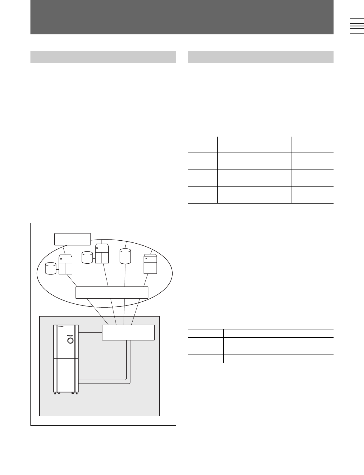
ConsolidatedStorageManagement(以下CSM)システムは、大
容量のデータ処理とバックアップや階層型ストレージ管理を、高速
で確実に実行するシステムです。
必要なソフトウェアとハードウェアを 一体化することにより、信頼性
の高いストレージソリューションシステムを構築します。
CSMシステムは、テープライブラリーPetaSite S200シリーズ、
PetaSiteコントロールソフトウェア DZC-PSC2、PetaSiteコントロール
ユニット(PCU)、ア プリケーションソフトウェア PetaBackまたは
PetaServe、ファイバ ー チ ャネ ル ス イッチ(オプション)で構成され ま
す。
PetaSiteS200シリーズは、SuperAITフォーマットのカートリッジ を 管
理し、大量のデータを高速で保管/検索/記録/再生するテープラ
イブラリー シ ス テ ム で 、ベーシックストレージシステムにPetaSiteコン
トロールソフトウェア DZC-PSC2 およびPetaSiteコントロールユニッ
トをビ ルトインした パッケ ージシステムです。
Ethernet
PetaSite S200
シリーズ商品構成
ベーシックストレージシステム
CSM-200BF/200BS/100BF/100BS/60BF/60BS
ベーシックストレージシステムには、FC対応のS-AITドライブを搭載
したモデルとSCSI対応のS-AITドライブを搭載したモデルがあり、
それぞれカートリッジ 収納巻数の異なる3タイプが用意されていま
す。ドライブはそれぞれ 12 台まで搭載可能です。
ベーシックストレージシステム商品構成
モデル名 搭載 カートリッジ データ容量
ドライブ 収納数
CSM-200BF FC
CSM-200BS SCSI
CSM-100BF FC
CSM-100BS SCSI
CSM-60BF FC
CSM-60BS SCSI
さらに、別売りの 冗 長ライブラリー 専用電源CSMA-PSLと冗長ドライ
ブ専用電源CSMA-PSD、冗長ドライブIFボードキットCSMA-DIFを
使用すれば、信頼性の高いシステムを容易に構築することが可能
になります。
最大216 巻 最大108TB
最大108 巻 最大54TB
最大60 巻 最大30TB
アプリケー
ションサーバー
データサーバー
Storage Area Network
PetaSite S200
(PetaSite
ハブ、ターミナルサーバー内蔵)
シリーズ
コントロールユニット、
サーバー
NAS
アプリケーション
クライアント
ファイバーチャネル
スイッチ
CSM
拡張コンソール
CSM-200D/200C
ドライブとカートリッジ が 搭 載できるドライブコンソールCSM-200Dと
カートリッジ のみが搭載できるカートリッジ コンソール CSM-200Cがあ
りま す 。
別売りの拡張ベルトキットお よ び拡張ケーブルキットを組み合わせる
ことに よって、1台のベーシックストレージシステムに対し最大 7 台ま
で増設することができます。
増設台数
1 CSMA-BLTS 不要
2〜3 CSMA-BLTS CSMA-CBLS
4〜7 CSMA-BLTL CSMA-CBLL
拡張ベルトキット
拡張ケーブルキット
5(J)
Page 8

概要
PetaSite S200
シリーズの特長
ヘテロジニアス環境を実現するSANソリューションに おける高 速ス
トレージサブシステムで、次のような特長を備えています。
大量データの保管を実現
ベーシックストレージシステムに拡張コンソールを組 合 わ せることに
よって、最大 96ドライブ構成で 1.49PB のデータを保管することが
できます。
それぞれ 1 台ごとの 最 大データ収納量は次のとおりです。
機種名 ドライブ カートリッジ 容量
搭載台数 収納数
CSM-200BF/200BS 4 216 108
8 204 102
12 192 96
CSM-100BF/100BS 4 108 54
8 108 54
12 108 54
CSM-60BF/60BS 4 60 30
86030
12 60 30
CSM-200C − 396 198
− 396 198
− 396 198
CSM-200D 4 348 174
8 336 168
12 324 162
ベーシックストレージシステム
拡張ユニット
CSM-200C
最大カートリッジ数 最大容量
CSM-200BF/200BS
を組み合わせた場合
(TB)
に
(TB)
CSM-200BF/200BS+
CSM-200C× 1 612 306
CSM-200C× 2 1008 504
CSM-200C× 3 1404 702
CSM-200C× 4 1800 900
CSM-200C× 5 2196 1098
CSM-200C× 6 2592 1296
CSM-200C× 7 2988 1494
バーコードによるカートリッジの管理
バーコードリー ダーユニットを内蔵し、カートリッジ に 貼り付けたバー
コードによりカートリッジ を 管 理し ます 。
容易なロボット制御
ロボット制 御 インターフェースは、SCSIおよびAPIに対応していま
す。
自己診断機能
ロボットの 自己診断のみならず、搭載しているカートリッジ の ステ ー
タスを、見やすいGUI(グラフィカル ユーザーインターフェース)で
表示します。
環境による高速データ転送
SAN
FC(FibreChannel:ファイバ ー チ ャネ ル )直結テープドライブを採
用し、高 速の デ ータ転 送を可能にしました。
の転送スピードと大容量
S-AIT
ドライブ1台当たり30MB/s(非圧縮時)
テープ 1巻当たり500GB(非圧縮時)
の負荷軽減とライブラリーシェアリングによる低コスト
LAN
LANフリーバックアップ、NDMPに対応しています。
リモートメンテナンス機能
SNMP対応
Java対応リモート監 視ソフトウェア
PC
サーバー
(PetaSite Control Unit)
内蔵
テープライブラリーを制 御、監視するPetaSiteControlUnit(PCU)
を内蔵しています。
PCUは、PetaServe や PetaBackのバックアップサーバーとしても
動作します。
6(J)
Page 9

拡張例
ベーシックシステムに拡 張コンソール 7 台まで増設し、容量を増やすことができます。
CSM-200BF/200BS
ご注意
CSM-100BF/BS、CSM-60BF/BSに拡張コンソールを接続するこ
とは できません。拡張コンソールを接続するときは、オプションの
アップ グレードキットを使用して、CSM-200BF/BSにアップグレード
してください。
CSM-200D/CSM-200C
7(J)
Page 10

概要
関連製品
CSMA-DR130F Storage Management System
Drive Unit (FC)
ホットスワップ 対 応 ライブラリー 専用のFCドライブユニットで す( ア
タッチメント込み)。
CSMA-DR100S Storage Management System
Drive Unit (SCSI)
ホットスワップ 対 応 ライブラリー 専用のSCSIドライブユニットで す(ア
タッチメント込み)。
CSMA-CBLL Extension Kit (CL)
拡張コンソール4〜7 台連結用の拡張ケーブルキットで す 。
CSMA-CBLS Extension Kit (CS)
拡張コンソール2〜3 台連結用の拡張ケーブルキットで す 。
CSMA-BLTL Extension Kit(BL
拡張コンソール4〜7 台連結用の拡張ベルトキットで す 。
)
CSMU-100B Upgrade Kit CSM-60BF/BS to
CSM-100BF/BS
CSM-60BF/BSを CSM-100BF/BS にアップグレードするキットで
す。
CSMU-200B Upgrade Kit CSM-100BF/BS to
CSM-200BF/BS
CSM-100BF/BSをCSM-200BF/BSにアップグレードするキットで
す。
DMSA-CPJ Power Cord
PetaSiteS200シリーズおよびPetaSiteコントロールユニット(PCU)
用の電源コードです(AC100V用)。
DMSA-CPE Power Cord
PetaSiteS200シリーズおよびPetaSiteコントロールユニット(PCU)
用の電源コードです(AC120V用)。
CSMA-BLTS Extension Kit(BS
拡張コンソール1〜3 台連結用の拡張ベルトキットで す 。
CSMA-PSL Redundant Power Unit (Library)
ホットスワップ 可 能 な 冗 長ライブラリー 専用電源ユニットで す。
)
CSMA-PSD Redundant Power Unit (Drive)
ホットスワップ 可 能 な 冗 長ドライブ専用電源ユニットで す。
CSMA-DIF Redundant Drive Control Unit
冗長ドライブ専用のインターフェースボードキットで す。
DMSP-KBE1/DMSP-KBJ1 PC Keyboard
DMSP-KMS1 PC Mouse
PetaSite S200シリーズに内蔵の PetaSite コントロ ー ルユニット
(PCU)用のキーボードとマ ウスで す。
8(J)
Page 11

システムの性能を保持するために
万一の故障を防ぎ、高い性能を維持するために、装置、メディアの
取り扱いの際には以下の点にご注意ください 。
装置の取り扱い
振動、衝撃を与えないでください。本システムは精密に作られてい
ますので、振動や衝撃が故障の原因になることがあります。
• 各装置の通風孔をふさがないでください。
• 性能を維持するために、システム内の各装置の定期点検を必ず
受けてください 。
メディアの取り扱い
• 磁気の強いものに近づけないでください。
• カートリッジ 内部のテープに手を触れないでください。
使用・保管場所について
システムの各装置、メディアともに次 のような場 所での使用、保管は
絶対に避けてください。
• 湿気の多いところ
• 温度の高いところ
• 直射日光があたるところ
• ほこりの 多いところ
• 激し い振動のあるところ
• 温度変化の激しいところ
• 水平でないところ
輸送について
本システムを輸送する場合は、PetaSiteコントロール ユニットを取り
外し、輸 送 用 金 具を取り付 けて 、 必 ず専 用の 梱 包 材 を 使 用 の 上、
輸送してください。
PetaSiteコントロー ルユニットの 取り外しは、サービストレーニングを
受けた技術者にご依頼ください。
PetaSite
コントロールユニットの取り付けにつ
いて
PetaSiteコントロールユニットの 取り付けは、サービストレーニング
を受けた技術者にご依頼ください。
クリーニングについて
外装部は、ぬるま湯または薄い中性洗剤で湿らせた布でふき、そ
の後からぶきしてください。
シンナー、アルコールなどの溶剤は使用しないでください。塗装部
分を傷 めるおそれがあります。
また、S-AITドライブのクリー ニ ン グ方法に関しては、S-AITドライブ
の取扱説明書をご覧ください 。
9(J)
Page 12
各部の名称と働き
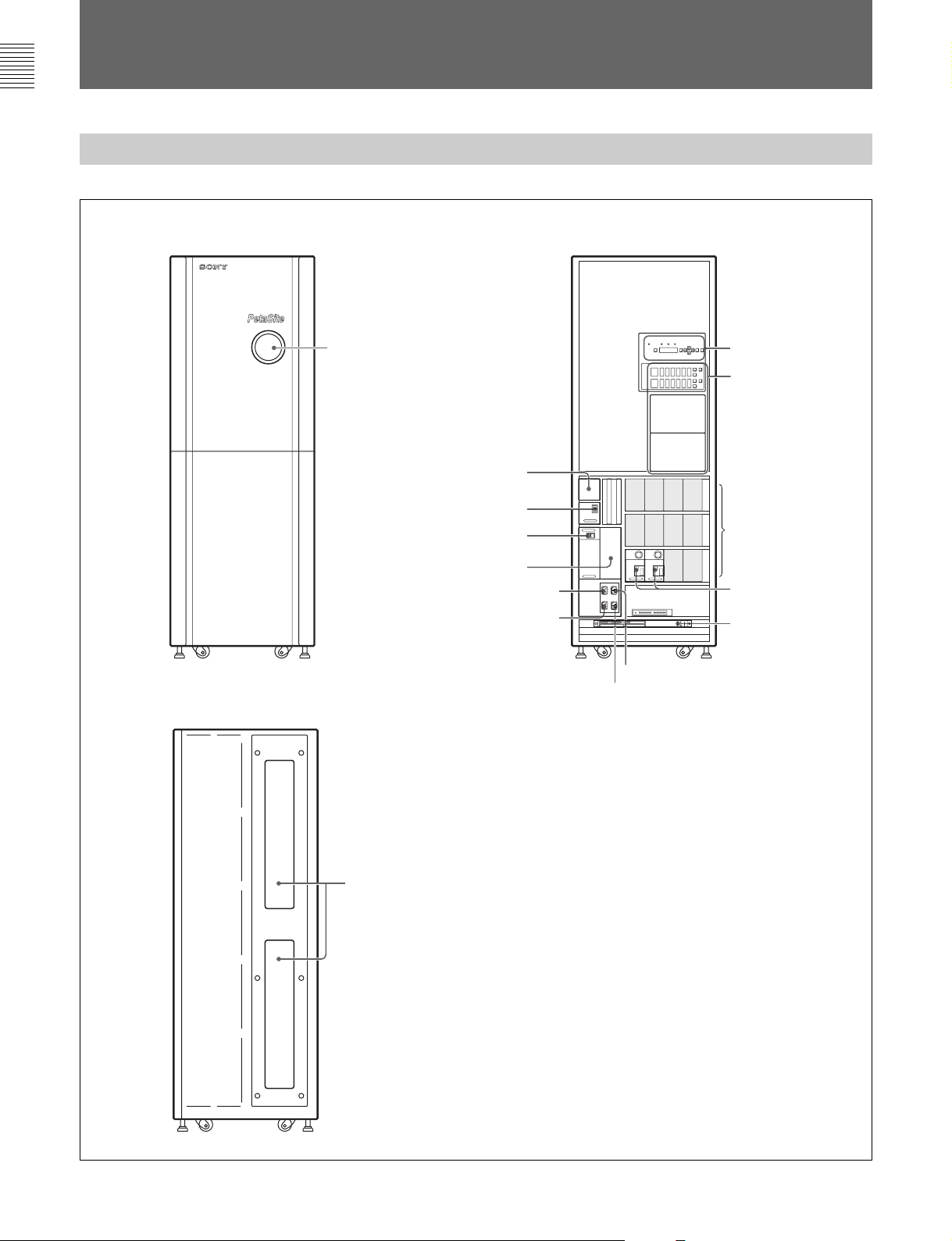
前面および側面
CSM-200BF/200BS/100BF/100BS/60BF/60BS
前面 正面内部
右側面
ディスプレイパネル
確認窓
オプションリダンダント電源用
スロット(ドライブ用)
1 電源スイッチ(ドライブ用)
2 電源スイッチ(ロボット用)
オプションリダンダント電源用
スロット(ロボット用)
インレット(ロボットリダンダント用)
AC
インレット(ロボット用)
AC
POWER READYBUSYERROR
INITIAL
MENU
123456
789101112
ESC/
CLR
ENTER
3 ディスプレイパネル
OPEN
OPEN
4
IN/OUT
オプションドライブ用
スロット
標準ドライブ
5
PetaSite
コントロール
ユニット
インレット(ドライブリダンダント用)
AC
インレット(ドライブ用)
AC
ポート
10(J)
6トランスファー確認窓
Page 13
1 電源スイッチ(ドライブ用)
ドライブ部の電源をON/OFFします。
電源を入れるときはI 側(入)にしま す。
O
電源を切るときは
側(切)にします。
5
PetaSite
ドライブおよびロボットを制御・監視するシステムです。
◆詳しくは「PetaSiteコントロ ー ル ユ ニ ット(PCU)」(13(J)ページ)をご覧く
ださい。
コントロールユニット
ご注意
•リダンダント電 源使用時に電源を切るときは、両方の電源スイッチ
を切ってください。
• 電源を切った直後に電源を入れるときは、5秒以上間隔を開けて
ください。
2 電源スイッチ(ロボット用)
ロボット部 の電源を ON/OFFします。
電源を入れるときはI 側(入)にしま す。
O
電源を切るときは
電源が切れると、ディスプレイパネルのインジケーターが すべ て消
えます 。
ご注意
•リダンダント電 源使用時に電源を切るときは、両方の電源スイッチ
を切ってください。
• 電源を切った直後に電源を入れるときは、ディスプレイパネ ル の
インジケーターが 消えるまで 待って から入 れてください。
側(切)にします。
6 トランスファー確認窓
トラン スファーの 移動状態/ 停止位置が確認できます。
この機器には、電源供給口(ACインレット)が4系統あります。電源
を完全に遮断するには、すべての電源コードを 抜 い てください。
3 ディスプレイパネル
本システムの運用状態、ステータス等を表示します。また、システ
ムの初期化や、メニュー操 作 による構成の確認、アワーズメーター
の確認などを行います。
◆詳しくは「 ディスプレイパネル」(12(J)ページ)をご 覧ください。
4
IN/OUT
カートリッジ の 出し 入 れ をしま す。ポートに は 6 巻 ま で カ ートリッジを 収
納できるマガジンを2 個搭載できます。
カートリッジの向きに注意して確実に投入してください。
◆詳しくは「 IN/OUTポート」(13(J)ページ)をご 覧ください。
ポート
11(J)
Page 14
各部の名称と働き
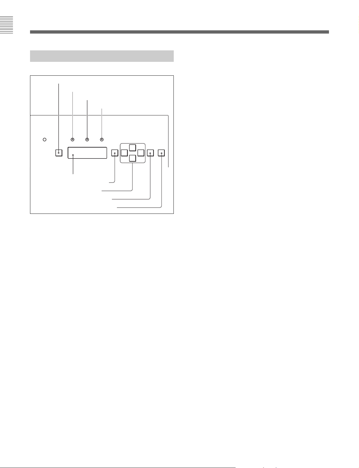
ディスプレイパネル
1
INITIAL
POWER READY BUSY ERROR
INITIAL
ボタン
2
READY
3
BUSY
5 表示部
6
MENU
7 矢印ボタン
8
ENTER
9
ESC/CLR
ボタン
インジケーター
4
ボタン
インジケーター
ERROR
MENU ENTER
インジケーター
F
f
ボタン
5 表示部
操作状態や、メニュー操作の項目を表示します。
6
(メニュー)ボタン
MENU
このボタンを押 すと、表示部にメニュー項目が表示されます。表示
部が消灯している場合は、表示が点灯します。この場 合はもう一 度
押してください。
◆詳しくは「 メニ ュー操作」(21(J)ページ)をご覧ください。
7 矢印ボタン
ESC/
CLR
gG
メニュー 操作時に、点灯しているボタンを押すと、次のメニュー項
目または数値が表示されます。
8
ENTER
(エンター)ボタン
メニュー 操作で、設定した内容を確定するときに押します。
9
ESC/CLR
(エスケープ/クリア)ボタン
メニュー 操作時に押すと、ひとつ前の状態に戻ります。
1
INITIAL
(イニシャル)ボタン
表示部にInitialRequestまたはFullInitialRequestが表示
され て いるとき、このボタンを押してシステムを初 期化します。ボタ
ンを 5 秒以上押し続けると初期化の動作を開始します。初期化中
はBUSYインジケ ーターが 点灯します。
本システムは、電源投入後は必ず初期化が必要です。
SetUpメニューのAutoInitialを有効にすると、電源投入後に自動
で初期化の動作を行います。
2
READY
(レディ)インジケーター
本システムが運用可能な状態のとき点灯します。
3
(ビジー)インジケーター
BUSY
本システムが動作中のとき点灯します。
初期化中も点灯します。
4
ERROR
(エラー)インジケーター
本システムに エラーが発生すると点灯します。
表示部の表示に従い以下の対応をしてください。
Initial Request
または
Full Initial Request
が表示されてい
る場合
INITIALボタンを押してシステムを初期化し直してください。
Power off Request
が表示されている場合
いったん電源を切ってから、再投入してください。
以上を実施しても復帰しない場合は、ソニーのサービス担当者に
連絡してください。
12(J)
Page 15
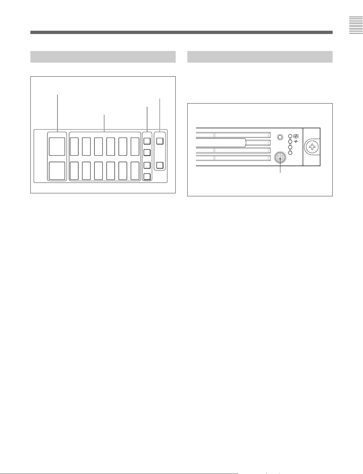
IN/OUT
1
NO MAGAZINE
ポート
インジケーター
2
IN /OUT
4
OPEN
3
ファンクションボタン
表示
ボタン
PetaSite
コントロールユニット(
PCU
)
ドライブおよびロボットを制御・監視するシステムです。
PetaServeやPetaBackのアプリケーションサーバーとしても動作し
ます。
123456
NO
MAGAZINE
NO
MAGAZINE
1
NO MAGAZINE
IN
OUTINOUTINOUTINOUTINOUTINOUT
7891011 12
IN
OUTINOUTINOUTINOUTINOUTINOUT
(ノーマガジン)インジケーター
マガジンが入っていないときに赤く点灯します。
2
IN/OUT
表示
各カートリッジ スロットの 状態を 表 示します 。
のみ点灯: カートリッジ が 投 入され たことを示します。
IN
のみ点灯: 使用済みのカートリッジ が 排 出され たことを 示し
OUT
ます。
同時点灯:
カートリッジ の バ ーコードを読 むと IN とOUTが点灯し
ます。使用モードによっては、点灯する前にカートリッジ を 取り
込むこともあります。
同時点滅:
カートリッジ に バーコードラベ ルが貼られていない場合、
あるい はなんらか の 理由で読めない場合にINとOUTが点滅
します。
OPEN
OPEN
POWER
POWER
スイッチ
PCUの電源をON/OFFします。
UID
スイッチ
NIC
1
NIC
2
3 ファンクションボタン
ソフトウェア で 機 能を 設定します。
4
(オープン)ボタン
OPEN
カートリッジ を出し 入 れ するときに 、このボタンを押して 扉を開きま
す。
扉が開いている間、ボタンは点灯します。
動作状態によって、扉が開くまでに時間がかかる場合があります。
エラーが発生するとボタンは点滅します。
13(J)
Page 16
準備
設置について
各機器の設定や配線、および環境設定はCSMシステムおよび
PetaSiteシリーズのサービストレーニングを受けた 技 術者にご依頼
ください。
接続例
2TB のデータを8 時間でフルバックアップするシステム例です。
アプリ
ケーション
サーバー
SUN Solaris
500GB
ネットワーク
アプリ
ケーション
サーバー
HP-UX
500GB
サーバー
NAS
NetApp
ラー
1TB
ファイ
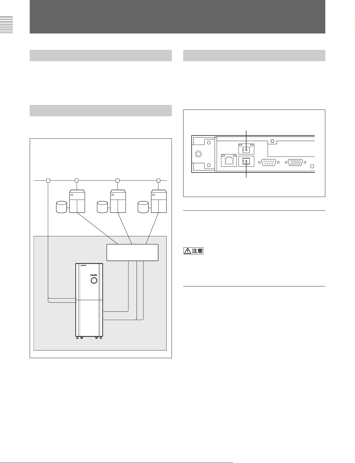
PCUのEthernet I/F
PetaSiteコントロールユニット(PCU)は EthernetI/Fポートを2個
持っています。1つはPetaSiteシステム制御用のローカルネットワー
ク用、もう1 つは PetaSiteシステム以外のネットワーク用 の ポ ートで
す。
PCU
外部ネットワーク用
PetaSite
PetaSite
システム制御用
Ethernet I/F
システムのネットワーク用ポート
ポートについて
リアパネル
Ethernet I/F
ポート
ポート
PetaSite
シリーズ
S200
(
PetaSite
コントロール
ユニット内蔵)
ファイバーチャネル
スイッチ
用
CSM
PetaServe/PetaBack
ソフトウェア
PetaSiteシステム制御用のネットワークには 、本システム用 の機 材
以外は接続しないでください。
安全のため、LANポートに は 過 電圧が加わるおそれのないネット
ワークに接 続してください。
PetaSite
こちらのポートは ネットワーク管 理 者よりIPアドレ スを 取 得し 、設定し
ます。
◆設定方法については、「PCUのホスト名 /IPアドレ スの 設定」(15(J)ペー
ジ)をご 覧ください。
システム以外のネットワーク用ポート
14(J)
Page 17

設定
4 新しい パスワード(変更したいパスワード)を2回聞かれるの
で、それぞれプロンプトに 続 けて新しいパスワードを 入力する。
DZC-PSC2
PCUに は PetaSiteコントロー ルソフトウェア DZC-PSC2が
工場出荷時に導入され、動作に必要な初期値は設定されています
が、使用環境に合わせて設定を変更する必要があります。
◆設定変更などの操作方法については、DZC-PSC2のオンラインヘルプを
ご覧ください。
オンラインヘルプは、DZC-PSC2のMMTウィンドウ の[Help]ボタンをク
リックす ると参 照 す ることが で きま す。
DZC-PSC2
次の手順で起動します。
の初期設定について
の起動
1 PCUの電源を入れる。
2 ログイン画面で、Usernameにsonypsc、Passwordにpsc2002
(初期パスワード)を入力する。
3 デスクトップにあるPetaAppのアイコンをクリックする。
これで、次のログインのときに新しいパスワードが有効になります。
のホスト名
PCU
PCUには、ホスト名/IPアドレスを 鍵に 設 定され てい るファイル がい
くつ か ありま す 。CSMシステムの導入時にホスト名 /IPアドレスを 設
定して、これらのファイルに設定を反映させる必要があります。下記
の手順でホスト名 /IPアドレスを 設 定し てください。上記ファイルに
設定が反映されます。
ご注意
CSMシステムでは運用開始後は基本的にホスト名 /IPアドレスの
変更はできません。やむをえず変更の必要が生じた場合は、ソ
ニーのサポートセンターまでご 連絡ください。
アドレスの設定
/IP
1 Usernameにrootと入力してログインし 、ターミナ ル画面を1つ
起動しておく。
2 デスクトップ の PetaAppアイコンを クリックする。
工場出荷時の初期パスワードを変 更した い場合は、DZC-PSC2 の
オンラインヘルプをご覧ください 。
でのログインについて
root
管理者用のアカウントrootでログインするには、ログイン画面で
Usernameに root、Passwordにsony2002(初期パスワード)を入
力します。
パスワードを変更するには
パスワードを変更したい場合は、次の手順で操作します。
1 パスワードを変 更したいユーザー名でログインする。
2 ターミナ ル画面を開き、passwdと入力し、Enter キーを押す。
3 今までのパスワードを聞 かれるので、プロンプトに 続 けてパス
ワードを 入力する。
3 Utilityアイコンを クリックし て、ユーティリティ画 面 を 起動する。
4 ユーティリティ画 面右上の Modeリストボックスで
Administratorを選択する。
5 Passwordに sony(初期パスワード)を入力する。
6 ユーティリティ画面のNetworkタブをクリックして選択する。
7 注意書きをよく読み、画面下のNetwork Configuratorを
クリックし、NetworkConfiguratorを起動する。
8 Names画面で HostName欄に新しいホスト名 、Domain 欄に
新しいドメイン名を入力する。
9 Hosts画面で新しいホスト名、IPアドレスと運 用 に必要なホスト
名、IPアドレスの関係を追加する。
10Interface画面でeth1側のIPアドレスを 新しい I P アドレスに 変
更する。
15(J)
Page 18

準備
11NetworkConfigurator画面下の[SAVE]ボタンをクリックし、
設定事項を保存する。
12[Cancel]ボタンをクリックして、PetaAppユーティリティ画 面 を
終了する。
13コマンドラインから下記のコマンドを入 力し 、Enterキーを押し
て実行する。
# /osm/bin/app_sethostname
14手順 1 で開いておいたターミナ ル画面で/sbin/init6を入力
し、Enterキーを押してPCUを再起動する。
のタイムゾーンの設定変更
PCU
1 Usernameに rootと入力してログインし 、ターミナ ル画面を起
動する。
2 以下のコマンドを 入 力し て、TimezoneConfiguratorを起動す
る。
dateのオプションは MMDDhhmmYY(MMは月、DDは日、hhは
時、mmは分、YYは年)となります。
◆詳しくは、date--helpまたはmandateと入力してオンラインマニュアル
を参照してください 。
の設定を変更して、画面が表示されなく
PCU
なったら
1 [Ctrl]+[Alt]+[F6]を同時に押す。
テキストベ ースのログイン画面が 表示されます 。
2 rootでログインする。
3 以下のコマンドを 入 力して、Xserverを設定しなおす。
# /usr/bin/redhat-config-xfree86 --noui --reconfig
4 以下のコマンドを 入力してPCUを再起動する。
# /sbin/init 6
# /usr/sbin/timeconfig
#:rootでのコマンドプロンプト
3 設定したいタイムゾーンにフォーカスを合わ せ、[OK]ボタンを
クリックする。
• 入力項目の移動はTABキーを使います。
• 設定項目の移動は上下の矢印キーを使います。
ご注意
一番上の入力項目([]ハードウェアクロックをGMTに合わせて設
定する/[]HardwareclocksettoGMT)のチェックボックスの
空欄を、スペースキーを押して[*]にし てください。ここに チ ェック
([*])を入れないと、PCU の時刻の設定が変わってしまう場合が
あります 。
時間を合わせるには
rootユーザーでdateコマンドを 使 用します。最初にタイムゾーンを
設定してから、以下のように入力します。
2002年1月23
# /bin/date 0123045602
日午前4:56に設定するには:
表示周波数外の設定になってしまったら
モニター画面にメッセージ OutofRangeなどが表示され、表示周
波数外の設定になってしまった場合も、前項「PCUの設定を変更
して、画面が表示されなくなったら」と同様の手順で、PCUを再起
動してください。
DZC-PSC2
のリモートメンテナンスツールの
インストール
他のコンピューターからサー バ ーの状 態を監視し たり、メンテナンス
を行なうために、リモ ートメンテナンスツールをインストー ルします。
リモートメンテナンスツールをインストールするには、CSMシステムの
場合は、PetaAppClientInstallKitディスクの PetaAppGUI/ 以下
のインストー ル キットを 使 用します。DZC-PSC2単体の場合には、
DZC-PSC2の InstallKit ディスクの Remote/ 以下のインストー ル
キットを使用します。
リモ ートメンテナンスツールを使用するには、サーバーのDZC-PSC2
への設定も必要です。
◆詳しくは、DZC-PSC2 のオンラインヘルプを参照してください。
#:rootでのコマンドプロンプト
16(J)
Page 19

ご注意
•リモ ートメン テナン スツー ルを 実行するには、Java Run Time
Environment(JRE 1.4.1)が必要です。InstallKitディスクの
toolsの下にRedHatLinux7.1/8.0 用、Solaris用、Windows 用
のJREが入っていますのでインストー ルし て 使 用し てください。
◆詳しい情報は、以下のURLを参照してください。
http://java.sun.com/products/plugin/1.3/docs/ja/
quickstart.html
•リモ ートメン テ ナン スツ ー ルのオンラインヘルプを利用するには、
ウェブブラウザーが必要です。以下のウェブブラウザーにおける
動作が確認されています。
Netscape7.01(6.xは未確認)
InternetExplorer5.5以上
Mozilla1.1.2以上
InternetExplorer では、オンラインヘルプ の表示が乱れる場合
がありま す。そのような場合には、画面を再度読み込み直してく
ださい。
リモートメンテナンスツールをインストールするには
Windows
Windows/の下のSetup.exeを起動します。
の場合:
NPX_PLUGIN_PATH="{JRE
sparc/ns4"
export NPX_PLUGIN_PATH
ご注意
RedHatLinux の場合には、NPXPLUGINPATHの sparc
の部分は i386になります。
のインストー ル 先
}/plugin/
2 オンラインヘルプの起動ファイル {DZC-PSC2 のインストー ル
先}/bin/webhelpで、環境変数BROWSERとXAPPLRESDIR
を以下のように設定する。
setenv BROWSER {Netscape
setenv XAPPLRESDIR {Netscapeのdefault
例: setenv XAPPLRESDIR /usr/openwin/lib/locale/
ja/app-defaults
ご注意
webhelpの初期設定で、BROWSERは RedHatLinux7.1/
8.0のデフォルトに 設 定されて います ので、以下の行の頭に#
を入れてコメントア ウトしてください。
#setenv BROWSER /usr/bin/netscape
のインストー ル 先
}/netscape
設定ファイル
}
UNIX(Solaris 2.6/7/8
場合:
Unix/の下のpainstallを実行します。
Solarisで使用する場合には、インストール後に環境変数を設定しま
す。RedHatLinux7.1/8.0 の場合には、rpmパッケージでインス
トー ル されるデフォルトの 設 定とな って いるの で 、設定は不要です。
ただし、Netscape や JREをデフォルトと違う場所に移動した場合
は、Solaris の設定を参考にして環境変数を設定してください 。
Solaris
の環境で使用する場合の環境変数を設定するには
および
Red Hat Linux 7.1/8.0
)の
1 シェルの設定ファイル で、環境変数 JAVABINと NPX
PLUGINPATHを以下のように設定する。
の場合: .cshrc に以下の行を追加する。
csh
setenv JAVABIN {JRE
setenv NPX_PLUGIN_PATH {JRE
plugin/sparc/ns4
の場合:以下のように環境変数の設定を行なう。
sh
J
AVABIN="{JRE
export JAVABIN
のインストー ル 先
のインストー ル 先
}/bin/java
のインストー ル 先
}/bin/java"
}/
リモートメンテナンスツールを起動するには
リモ ートメンテナンスツールの3つのGUI(PetaAppMonitorGUI、
BetaBackGUI、Monitoring&MaintenanceTerminalGUI)は、
まず PetaAppMonitorGUIを起動し、次にこのGUIから残りの2つ
のGUIを起動します。
Windows
PetaApp Monitor GUI
Monitoring & Maintenance Terminal GUI
PetaBack GUI
の場合:
の起動:[スタート]ボタンの[プログ
ラム]の中の[PetaAppController]から、[PetaAppMonitor]
を選択し て PetaAppMonitorGUIを起動します。
の起動:
PetaAppMonitorGUIで[PetaSite]ボタンをクリックします。
Monitoring&MaintenanceTerminalGUIが起動します。
の起動:PetaBackGUIはウェブブラウザーから
URLアドレ スを指 定し て起 動し ます 。
PetaAppMonitorGUIで[PetaBack]ボタンをクリックすると、
ウェブブラウザ ーが起動します。サーバー(PCU)では、自動
的にPetaBackGUIのURLアドレ スで ウェブ ブラウザ ーが起動
します。リモ ートの 場 合 は URLアドレスの指 定が 必要です。
PCUで PetaBackGUIを起動したときのURLアドレスを 入 力
してください。
17(J)
Page 20

準備
の場合:
UNIX
PetaApp Monitor GUI
の起動:以下のコマンドを 入力します。
% {DZC-PSC2
%:コマンドプロンプト
PetaAppMonitorGUIが起動します。
Monitoring & Maintenance Terminal GUI
PetaAppMonitorGUIで[PetaSite]ボタンをクリックします。
Monitoring&MaintenanceTerminalGUIが起動します。
PetaBack GUI
URLアドレスを 指 定し て起 動します 。
PetaAppMonitorGUIで[PetaBack]ボタンをクリックすると、
ウェブブラウザ ーが起動します。サーバー(PCU)では、自動
的にPetaBackGUIのURLアドレ スで ウェブ ブラウザ ーが起動
します。リモ ートの 場 合 は URLアドレスの指 定が必要です。
PCUで PetaBackGUIを起動したときのURLアドレスを 入 力
してください。
のインストー ル 先
の起動:PetaBackGUIはウェブブラウザーから
}/bin/petaapp
の起動:
18(J)
Page 21

操作
始動手順
始動させる手 順 は 、次 の通りで す。
1 CSM-200BF/200BS/100BF/100BS/60BF/60BSのドライブ
用電源スイッチとロボット用電源スイッチを、両方ともI側(入)
にする。
2 オプションでファイバ ー チ ャネ ル スイッチがシステムに組み込ま
れているときは 、そ の電 源 を O N に する。
(ファイバ ーチ ャネル スイッチ が 動 作可能な状態になるまで
約3分間かかります。)
3 PCUの電源をONにする。
4 Usernameに sonypscを入力し、ログインする。
5 デスクトップ の PetaAppアイコンをクリックし て、PetaAppを起
動する。
停止手順
1 すべてのアプリケーションを停 止する。
2 すべてのドライブにカートリッジ が 入 っ て いないことを確認する。
3 PCUを次の手順で終了する。
)Usernameにrootを入力してログインする。
1
)ターミナ ル画面で次のように入力する。
2
# /sbin/init 0
または
# /sbin/poweroff
#:rootでのコマンドプロンプト
各プロセスの停止状況が表示されます。
)最後に以下の表示が出たら前 面の 電 源ボタンを 押 して電
3
源を切る。
Halting system....
Stopping all md devices.
Power down
4 オプションでファイバ ー チ ャネ ル スイッチがシステムに組み込ま
れているときは 、そ の電源を切る。
5 ドライブ用電源スイッチを
6 ロボット用電源スイッチを
O
側(切)にする。
O
側(切)にする。
19(J)
Page 22

操作
カートリッジの挿入と取り出し
カートリッジの挿入と取り出しの手順は、次のとおりです。
1 IN/OUTポートの OPEN ボタンを押す。
扉が開きます。
2 マガジンを引き出 す 。
ご注意
カートリッジ に 衝 撃 を与えないように、ゆっくりとマガジンを引き
出してください。
マガジンを引き出した後、カートリッジ を出し 入 れする側を下に
向けないようにご注意ください。下に向けた状態で衝撃が加え
られると、カートリッジ が落下する可能性があります。
3 マガジンにカートリッジを 出し 入れする。
入れるときは、カートリッジ の バ ーコードが 見える向きで、SONY
などの 文字印刷面を下図に示す向きにして入れます。
バーコード
SA1 500
GB
4 マガジンを元どおり装 着する。
ご注意
カートリッジ に 衝 撃を 与えないように、ゆっくりとマガジンを押し
込んでください 。
5 扉を閉 める。
ご注意
カートリッジ に 衝 撃を 与えないように、ゆっくりと扉を閉めてくだ
さい。
20(J)
Page 23

メニュー操作
Set Up
項目を設定をするには
ディスプレイパネルの MENUボタンを押すと、表示部に次のメ
ニュー項目が 1 つ表示されます。
Hours Meter
Console:電源投入時の合計時間
I/O1(×1000):上 の IN/OUTポート扉 の開 いた回数(×1000回)
I/O2(×1000):下 の IN/OUTポート扉 の開 いた回数(×1000回)
Access(×1000):トラン スファーの 移動回数(×1000 回)
X:トラン スファーのX軸(横方向)の移動距離(km)
Y:トラン スファーのY軸(縦方向)の移動距離(km)
Z:キャリア のZ軸(奥行き方向)の移動距離(km)
R:キャリア のR軸(回転方向)の移動回数(×1000 回)
Program Version
ファー ムウ ェア の バ ージョンを表 示します。ファームウェアは CCC、
SV1、RCX、RCY、RCR、RCZ の6 種類あります。
Set Up
SerialNo.(シリアルナンバーの表示)
Date(日付の表示)
Time(時間の表示)
LCDContrast(表示部のコントラストの 調整)
AutoInitial(自動初期化の設定)
Configuration
コンソールの構成を英数字で表示します。
B:CSM-200BF/200BS
1:CSM-100BF/100BS
6:CSM-60BF/60BS
D:CSM-200D
C:CSM-200C
SetUpメニューの各項目は、必要に応じて次の手順で設定しま
す。
1 MENUボタンを押して、表示部にメニューを表示させる。
2 矢印ボタンを押して、SetUpの設定したい項目を表示させる。
3 矢印ボタンを押して、設定したい数値を表示させる。
4 ENTERボタンを押す。
手順3 で設定した値が確定します。
手順2〜 4を必要なだけ繰り返します。
メニュー表示を1つ前の状態に戻すには
ESC/CLRボタンを押します。
メニューから抜けるには
ディスプレイパネル に、HoursMeter、ProgramVersion、
SetUpまたはConfigurationが表示され ているときに、ESC/
CLRボタンを押します。
表示する項目を選択するには
表示項目は、矢印ボタンを押し て 選択します。矢印ボタンが点灯し
ている場合は、さらに 表示する項目があります。点灯しているボタ
ンを押し てください。
21(J)
Page 24

操作
の再起動
PCU
1 Usernameに rootと入力してログインする。
2 ターミナ ル画面で次のように入力する。
# /sbin/init 6
#:rootでのコマンドプロンプト
各プロセスの停止状況が表示され、その後再起動します。
の電源がONのとき途中で停止してしまっ
PCU
た場合の再起動
PCUの電源を正しい手順で切らなかった場合や停電が発生した
場合などは、PCUの電源をONにしても、次のような表示が出て、
起動が途中で停止することがあります。
*** An error occurred during the file system check.
*** Dropping you to a shell; the system will reboot
*** when you leave the shell.
Give root password for maintenance
(or type Control-D for normal startup):
4(Repairfilesystem)2#と表示されたら、init6と入力し、Enter
キーを押して再起動する。
(Repair filesystem) 2# init 6
修復が完了していれば、正常に起動します。
再起動中に起動が停止した場合
再起動中に起動が停止した場合、次の表示が出ます。
/export/home:UNEXPECTED INCONSISTENCY; RUN fsck
MANUALLY.
(i.e., without -a or -p options)
*** An error occurred during the file system check.
*** Dropping you to a shell; the system will reboot
*** when you leave the shell.
Give root password for maintenance
(or type Control-D for normal startup)
障害があると表示されたファイルシステムは、次の手順で修復して
ください。
1 UNEXPECTEDINCOSISTENCY;と表示された行の最初に
表示されているディレクトリ名 を控 えて おく(上記の表示例の場
合は、/export/home)。
次の手順で再起動してください 。
1 rootユーザーのパスワードを入力する。
rootユーザーの初期パスワードは sony2002です。
(Repairfilesystem)1#というプロンプトが表示されます。
2 fsck-Aと入力し、Enter キーを押す。
(Repair filesystem)1# fsck -A
このとき「Doyoureallywanttocontinue(y/n)?」と表示さ
れた場合は、yを入力する。
ファイル シ ステ ム の チェック処理が 起動し、チェック内 容 が 表
示され、最 後に XXXX<y>?(XXXXの部分にはFix、Clearなど
の文字列が入ります)と表 示されます。
3 (Repairfilesystem)2#と表示されるまで Enter キーを押す。
この行は以下のように表示される場合もあります(xは数字)。
/export/home:xxxx/xxxx files (x.x% non-contiguous),
xxxx/xxxx blocks [FAILED]
この場合も最初に 表 示されて いるディレクトリ名( /export/
home)を控えておいてください。
2 rootユーザーのパスワードを入力する。
(Repairfilesystem)1#のプロンプトが表示されます。
3 fsckに続けて手順1で控えておいたディレクトリ名 を 入力する。
(Repair filesystem)1# fsck /export/home
ファイル シ ステ ム の チェック処理が 起動し、チェック内 容 が 表
示され、最 後に XXXX<y>?(XXXXの部分にはFix、Clearなど
の文字列が入ります)と表 示されます。
22(J)
Page 25

4 (Repairfilesystem)2#と表示されるまでEnterキーを押す。
DZC-PSC2
の操作について
5 (Repairfilesystem)2#と表示されたら、init6と入力し、Enter
キーを押して再起動する。
(Repair filesystem)2# init 6
修復が完了していれば、正常に起動します。
正常に起動されず、上記の表示が出る場合は、手順 1〜5を繰り
返します。
UPS(Uninterrupted Power Supply
電源)について
UPSは、停電や電源トラブル発生時にデータの損傷を防ぐための
装置です。UPSを経由して電源を接続すると元電源からの電源供
給が途絶えた際、UPS内部の電池に切り換わり、PCUへの電源の
供給を続けることができます。
PCUのシリアルポートに UPSをケーブルで接続して、DZC-PSC2
の「システムのシャットダ ウ ンと UPSデバイスの使用に関する設定」
を行なうことに より、UPSの状態を監視して停電を検出すると自動
的にシャットダ ウン 処 理 を 実 行します 。
停電や電源トラブル 発生時のシステムの信頼性を向上させるため、
停電が多発するような地域へシステムを設置する場合には、UPSを
使用することを推奨します。
:無停電
PetaSiteコントロールソフトウェア DZC-PSC2の各機能の操作およ
び表示内容については、オンラインヘルプに表示されます。
オンラインヘルプは、DZC-PSC2のMMTウィンドウの[Help]ボタ
ンをクリックすると参照することができます。
のオンラインヘルプについて
MMT
MMT( Monitoring & Maintenance Terminal)は 、GUI
(GraphicalUserInterface)を使用し、本システムおよび搭載する
ドライブの状態の監視とメインテナンスを行います。
MMTは次の機能を持ってます。
•
PetaSiteおよび搭載ドライブのステータス表示
•
PetaSite内のカートリッジ についての情報表示
•
PetaSiteおよび搭載ドライブのファームウェアバ ージョン表示
•
ドライブの使用状況の監視
•
PSCおよびPetaSite、ドライブのログデータの収集および表示
•
PSCおよびPetaSiteについての各種設定
•
上記機能に対するオンラインヘルプ
プリインストール
PetaBack
について
PetaServe/
PCUにPetaServeおよびPetaBackがプリインストー ルさ れ て いま
す。
製造時に90 日のデモライセンスが インストー ル され て い ます の で 、
コンフィグレーションを行なうことに より、HSMおよびバックアップソ
フトウェアを試使用できます。
詳細については、PCU のPetaServeマニュアルのアイコンを クリッ
クして、READMEJ.TXT(日本語)または READMEE.TXT(英
語)を参照してください。
READMEを含むすべてのドキュメントは 、/osm/docディレクトリー
配下にインストー ル さ れ て い ま す 。
プリインストー ル PetaServe/PetaBackを使用する際のコンフィグ
レーションや、相互接続性に関わる環境などについては、ソニーの
営業担当者にご相談ください 。
実際の運用でPetaServe/PetaBackをご使用になる場合は、正式
なソフトウェアライセンスを購 入されることにより、継続して運用する
ことが で きます 。
23(J)
Page 26

操作
PetaApp Linux
PCUには、OSとして PetaApp Linuxを採用しています。この
PetaAppLinuxはRedHatLinux8.0ftp版をベースにしたソニー独
自のPetaApp Control Unit 専用の OS です。画面表示の中に
RedHat社に関連するものが表示されることがありますが、RedHat
社とは無関係です。RedHat社には問い合わせなどはしないようお
願いいたします。
GPL/LGPL
PetaAppLinuxは、GPL/LGPL適用ソフトウェアを 含 みます 。した
がって、PetaAppLinux内の該当ソフトウェアに つい てのソースコー
ドの入手、改変、再配布の権利があることをお知らせいたします。
PetaAppLinux で使用しているGPL/LGPL 適用ソースコードは、
下記のいずれかの方法で入手することができます。
• サーバーからのダウンロード
• CD-ROM の郵送
具体的な入手方法については、以下のURLにアクセスしてくださ
い。
について
について
各機材の初期設定値
工場出荷時の設定値は以下のとおりです。
PCU
Hostname/IP Address
初期アカウント/パスワード : root、sony2002
: petalocal.petadomain
(eth0)
10.0.0.100/255.255.255.0
: petahost.petadomain
(eth1)
192.168.20.3/255.255.255.0
: sonypsc、psc2002
CSM-200BF/200BS/100BF/100BS/60BF/
60BS
コントロールコンソール
IP Address
ドライブインターフェース
: 10.0.0.30(Basic)
http://www.sony.net/Products/Linux/
なお、ソースコードの中身についてのお問い合わせはご遠慮くださ
い。
本製品で提供しているソフトウェア DZC-PSC2およびFZC-PABS/
PABM/PABLは、開発上LGPL 適用ライブラリー であるglibcをダ
イナミックリンクという方 法 で 使用しています。したがって、LGPLの
規定により、これらのソフトウェア のソースコードは 提供しておりませ
ん。しかし、本ソフトウェアの 購入者に限り、購入者自身のための
修正、もしくはデバック目的によるオブジェクトコードの解 析は認め
られています。
IP Address
Port Number
: 10.0.0.40(Basic)
: 10.0.0.41(Redundant)
:10001(Basic/Redundant共通)
ファイバーチャネルスイッチ(ブロケード
SILKWORM 3800/3200
IP Address
初期アカウント/パスワード:admin、password
: 10.0.0.20(1 台目)
: 10.0.0.21(2 台目)
)(オプション)
24(J)
Page 27

DZC-PSC2/MMT
SetupのMail/RemoteMaintenanceを設定していなければ、初期
設定不要。
項目
Communication Port Condition
DMS TerminalServer 10.0.0.30,10001
DRV TerminalServer 10.0.0.40,10001
BinDivision 設定なし(ユーザーのシステム構成による設定が必要)
ReserveBin 設定なし
DriveCondition Drive1、Drive2 のみON(搭載するドライブのみチェック
ExecuteMode
BusNo. other のみ設定済み
UserID –
(以下、StandardSetupをPetaServeにして[Apply]をクリックすると自動設定) チェック有 =1 / 無 =0
AutoEntry 0
ThreadwithLoad 1
UnthreadatLoadError 1
UnthreadwithFastUnload 0
UnthreadwithHalfWayUnload 0
UnthreadwithEject 0
DriveAutoLoadMode 0
BCReadwithCassetteMove 0
EraseofNewTape 1
RecoverofDestroy 0
WaitforDriveUse 0
UseCassettewithoutBC 0
UPS チェック有 =1/ 無=0
UseUPS 0
Executemachineshutdown 1
AutoHeadCleaning
BinArea 設定なし
AutoRetension 設定なし
AutoTakeLog チェック有 =1/ 無=0
ErrorTakeLog 0
AutoTakeLog 0
CassettePrifix 初期設定のまま
Network 9000
DZC-PSC2/MMT
を入れることが 必 要 )
25(J)
Page 28

操作
CSMA-DR100S/CSMA-DR130F
項目
VendorID(0-99999999) 0 0
Vendorname(8characters) SONY SONY
VendorROMversion(4characters) 1.?? 1.??
Machinename(16characters) SDZ-100 SDZ-130
Interface(0:SCSI-WD/1:SCSI-WS/2:SCSI-UWD/3:SCSI-LVD/ 3 8
8:Fibrechannel/12:VRP)
Series(0:SAIT-1/1:SAIT-2/2:SAIT-3/3:SAIT-4) 0 0
Serialnumber ???????? ????????
SCSIID(0-15) 5 設定無し
LoopIDrequest(0:OFF/1:ON) 設定無し 1
LoopID(0-126) 設定無し 0
AutoThreadmode(0:OFF/1:ON)
WriteRetryCount(0-20) 0 0
ReadRetryCount(0-16) 0 0
FCportname ff.ff.ff.ff.ff.ff.ff.ff 50.80.04.60.12.10.??.??
FCnodename ff.ff.ff.ff.ff.ff.ff.ff 50.80.04.60.12.10.??.??
a)DZC-PSC2 の DrivePropertyダイアログボックスのSetupタブで、Standard
Setupリストボックスを Default に設定するとデフォルトで 選 択される設 定。
a)
CSMA-DR100S CSMA-DR130F
00
26(J)
Page 29

仕様
一般
電源 AC100V−240V、50/60Hz
消費電力
CSM-200BF/200BS/100BF/100BS/60BF/60BS
−
2.7A
6.5A
−
CSM-200C/200D 3.5A
外形寸法(幅/ 高さ/奥行き)
質量
CSM-200BF/200BS/100BF/100BS/60BF/60BS
CSM-200C/200D 300kg
発熱量 560kcal/h
1.5A
680× 1980× 950mm
350kg
性能/容量/その他
データ収納量 CSM-200BF/200BS:最大108TB
CSM-100BF/100BS:最大54TB
CSM-60BF/60BS:最大30TB
CSM-200C:最大198TB
CSM-200D:最大174TB
ドライブ搭載台数 12 台まで
環境条件
付属品
CSM-200BS/100BS/60BS
オペレーションマニュアル(1)
プラグホルダー(8)
ターミネ ーター(2)
バーコードラベ ルシ ート(14)
バーコードラベ ルシート(クリー ニ ング用)(2)
PetaAppLinuxリカバーCD-ROMdisk1、disk2(各 1)
PetaAppSoftwarePackageCD-ROMdisk1、disk2(各 1)
ライセンス証(1)(CSM-200BS/100BS のみ)
ディスプレイ延長 ケーブル(1)
キーボード/マウス延長ケーブ ル(各 1)
スパナ(1)
CSM-200BF/100BF/60BF
オペレーションマニュアル(1)
プラグホルダー(8)
バーコードラベ ルシ ート(14)
バーコードラベ ルシート(クリー ニ ング用)(2)
PetaAppLinuxリカバーCD-ROMdisk1、disk2(各 1)
PetaAppSoftwarePackageCD-ROMdisk1、disk2(各 1)
ライセンス証(1)(CSM-200BF/100BF のみ)
ディスプレイ延長 ケーブル(1)
キーボード/マウス延長ケーブ ル(各 1)
スパナ(1)
動作温度 +10℃〜+30℃
保存温度 − 20℃〜+60℃(カートリッジを 取り外し
ておくこと)
動作湿度 25%〜80%(結露しないこと)
バーコードリーダーの光学仕様
光源波長 赤色LED:630nm
受光素子 CCDリニアセンサー
スキャン速 度 5 0 0 スキャン / 秒
CSM-200D
プラグホルダー(4)
バーコードラベ ルシ ート(16)
スパナ(1)
CSM-200C
バーコードラベ ルシ ート(16)
スパナ(1)
27(J)
Page 30

仕様
別売りコンポーネント/アクセサリー
FCドライブユニット CSMA-DR130F
SCSIドライブユニット CSMA-DR100S
拡張ベルトキット CSMA-BLTS(拡張コンソール1〜 3
台連結用)
CSMA-BLTL(拡張コンソール4〜 7
台連結用)
拡張ケーブルキット CSMA-CBLS(拡張コンソール2 〜 3
台連結用)
CSMA-CBLL(拡張コンソール4〜7
台連結用)
電源ユニット CSMA-PSL(冗長ライブラリー 専用)
CSMA-PSD(冗長ドライブ専用)
冗長ドライブインターフェースボ ードキット
CSMA-DIF
アップ グレードキット CSMU-100B
CSMU-200B
キーボード DMSP-KBE1/DMSP-KBJ1
マウス DMSP-KMS1
電源コード DMSA-CPJ(AC100V)
DMSA-CPE(AC120V)
仕様および外観は、改良のため予告なく変更することがあります
が、ご了承ください。
本機は「高調波ガイドライン適合品」です。
注意
この装置は、情報処理装置等電波障害自主規制協議会
(VCCI)の基準に基づくクラ スA情報技術装置です。この装 置
を家庭環境で使用すると電波障害を引き起こすことがあります。
この場合には 使 用者が適切な対策を講ずるよう要求されること
があります。
S-AIT
構造 AME(蒸着)テープ
記録容量 500GB(非圧縮時)
転送速度 30MB/s(非圧縮)
の仕様
600m× 1/2シング ルリー ル
1.3TB(2.6:1圧縮時)
バーコードラベルの仕様
バーコードリー ダーユニットは CODE39に対応しています。付属の
バーコードラベルの仕様は以下のとおりです。
00007BS1
11.1 mm
ストップマージンスタートマージン
バーコードラベル
外形寸法 使用するカートリッジ のラ ベ ル フレーム
サイズに準拠
バーの幅細バー:0.432mm
太バー/ 細バー比 2.75:1
バーの長さ 11.1mm
ストップ / スタートマ ージン 8 mm
桁数 8桁(スタート/ ストップ コード含まず)
チェック デジットなし
ご注意
バーコードラベ ル はカートリッジ のラベル エリア内に貼り付けてくださ
い。また、はが れないように バーコードラベ ルをカートリッジ側に強
く押し 付 けてください。
28(J)
Page 31

WARNING
To prevent fire or shock hazard, do not expose the unit to
rain or moisture.
To avoid electrical shock, do not open the cabinet. Refer
servicing to qualified personnel only.
THIS APPARATUS MUST BE EARTHED.
CAUTION
The mains plug on this equipment must be used to
disconnect mains power.
Please ensure that the socket outlet is installed near the
equipment and shall be easily accessible.
Use the power cord set approved by the appropriate testing
organization for the specific countries where this unit is to be
used
WARNING: THIS WARNING IS APPLICABLE FOR USA
ONLY.
If used in USA, use the UL LISTED power cord specified
below.
DO NOT USE ANY OTHER POWER CORD.
Plug Cap Parallel blade with ground pin
(NEMA 5-15P Configuration)
Cord Type SJT or SVT, three 16 or 18 AWG wires
Length Less than 2.5 m (8 ft. 3 in.)
Rating Minimum 10 A, 125 V
For the customers in Canada
This Class A digital apparatus complies with Canadian ICES-
003.
English
Caution for LAN port
For safety reason, do not connect the LAN port to any
network devices that might have excessive voltage.
AVERTISSEMENT
Afin d’éviter tout risque d’incendie ou d’électrocution, ne pas
exposer cet appareil à la pluie ou à l’humidité.
Afin d’écarter tout risque d’électrocution, garder le coffret
fermé. Ne confier l’entretien de l’appareil qu’à un personnel
qualifié.
CET APPAREIL DOIT ÊTRE RELIÉ À LA TERRE.
WARNUNG
Um Feuergefahr und die Gefahr eines elektrischen Schlages
zu vermeiden, darf das Gerät weder Regen noch
Feuchtigkeit ausgesetzt werden.
Um einen elektrischen Schlag zu vermeiden, darf das
Gehäuse nicht geöffnet werden. Überlassen Sie
Wartungsarbeiten stets nur qualifiziertem Fachpersonal.
DIESES GERÄT MUSS GEERDET WERDEN.
For the customers in the USA
This equipment has been tested and found to comply with
the limits for a Class A digital device, pursuant to Part 15 of
the FCC Rules. These limits are designed to provide
reasonable protection against harmful interference when the
equipment is operated in a commercial environment. This
equipment generates, uses, and can radiate radio frequency
energy and, if not installed and used in accordance with the
instruction manual, may cause harmful interference to radio
communications. Operation of this equipment in a residential
area is likely to cause harmful interference in which case the
user will be required to correct the interference at his own
expense.
Pour les utilisateurs en Canada
Cet appareil numérique de la classe A est conforme à la
norme NMB-003 du Canada.
For the customers in Europe
WARNING
This is a Class A product. In a domestic environment, this
product may cause radio interference in which case the user
may be required to take adequate measures.
Pour les utilisateurs en Europe
AVERTISSMENT
Il s’agit d’un produit de Classe A. Dans un environnement
domestique, cet appareil peut provoquer des interférences
radio, dans ce cas l’utilisateur être amené à prendre des
measures appropriées.
Für Kunden in Europa
Warnung
Dies ist eine Einrichtung, welche die Funk-Entstörung nach
Klasse A besitzt.
Diese Einrichtung kann im Wohnbereich Funkstörungen
verursachen; in diesem Fall kann vom Betreiber verlangt
werden, angemessene Maßnahmen durchzuführen und
dafür aufzukommen.
Für Kunden in Deutschland
Diese Ausrüstung erfüllt die Europäischen EMCBestimmungen für die Verwendung in folgender / folgenden
Umgebung(en):
• Gewerbegebiete
• Leichtindustriegebiete
(Diese Ausrüstung erfüllt die Bestimmungen der Norm
EN55022, Klasse A.)
You are cautioned that any changes or modifications not
expressly approved in this manual could void your authority
to operate this equipment.
The device requires shielded interface cable to comply with
FCC emission limits.
Dieses Gerät ist nur für den Gebrauch in Gewerbe und
Leichtindustrie bestimmt.
1(E)
Page 32

LED Notice:
The LED of the barcode reader incorporated inside this
product complies with IEC 60825-1.
This product is classified as a CLASS 1 LED PRODUCT.
LED (barcode reader)
Wavelength 630–660 nm
For models with FC-conforming SAIT drives
Laser Notice:
The equipment contains tape drives using laser that
complies with IEC 60825-1.
The equipment is classified as a CLASS 1 LASER
PRODUCT.
CAUTION
The use of controls or adjustments or performance of
procedures other than those specified herein may result in
hazardous radiation exposure.
CAUTION
Do not look at the end of optical connector of the internal
tape driver with naked eyes or through optical equipment
while the power is supplied to this product. Otherwise, your
eyes may be injured
Caution to service personnel:
This equipment has four power supply connections. Power
to drive operation is supplied through appliance inlets
marked with DRIVE. Power to robot mechanism is supplied
through appliance inlets marked with ROBOT. All
connections need to be removed to completely de-energize
the equipment.
2(E)
Page 33

Table of Contents
Overview............................................................................................... 4(E)
Product Line-up of the PetaSite S200-Series ..................................4(E)
Features of the PetaSite S200-Series ...............................................5(E)
Extension Example..........................................................................6(E)
System Equipment........................................................................... 7(E)
Notes on Maintaining the Performance of
the System ..................................................................................... 8(E)
Locations and Functions of Parts....................................................... 9(E)
Front and Side ................................................................................. 9(E)
Display Panel................................................................................. 11(E)
IN/OUT Ports ................................................................................12(E)
PetaSite Control Unit (PCU) .........................................................12(E)
Preparations ....................................................................................... 13(E)
Installation .....................................................................................13(E)
Connection Example .....................................................................13(E)
Ethernet Interface Ports of the PCU ..............................................13(E)
Settings ..........................................................................................14(E)
Operations .......................................................................................... 18(E)
Starting Up .................................................................................... 18(E)
Ending ........................................................................................... 18(E)
Installing or Removing Cartridges ................................................19(E)
Menu Operation............................................................................. 20(E)
Restarting the PCU ........................................................................21(E)
Operations of the DZC-PSC2........................................................22(E)
Preinstalled PetaServe/PetaBack ...................................................22(E)
PetaApp Linux............................................................................... 23(E)
GPL/LGPL ....................................................................................23(E)
Initial Settings of Device ...............................................................23(E)
Specifications...................................................................................... 26(E)
Specifications of SAIT ..................................................................27(E)
Specifications of Barcode Reader .................................................27(E)
3(E)
Page 34

Overview
The Consolidated Storage Management (CSM) System
achieves rapid and accurate processing, backup, and
hierarchical
storage management of large amounts of
data.
The required software and hardware are configured
into one package to construct a storage solution system
of high reliability.
The CSM system is composed of PetaSite S200-series
tape libraries, DZC-PSC2 PetaSite control software,
PetaSite Control Unit (PCU) , PetaBack or PetaServe
backup application software, and fibre channel
switches.
The PetaSite S200-series is a tape library that controls
cartridges of the Super AIT format to store, check,
record, and reproduce large amounts of data at high
speed. It contains the PetaSite Control Unit and DZCPSC2 PetaSite control software in the Basic Storage
System models as a package.
Ethernet
Product Line-up of the PetaSite
S200-Series
CSM-200BF/200BS/100BF/100BS/60BF/60BS
Basic Storage System
There are models with FC-conforming SAIT drives
and models with SCSI-conforming SAIT drives. They
are further configured into three types according to the
number of cartridges to be stored. Up to 12 drives can
be mounted in any types.
Basic Storage System models
Model Mounted Number of Data
CSM-200BF FC
CSM-200BS SCSI
CSM-100BF FC
CSM-100BS SCSI
CSM-60BF FC
CSM-60BS SCSI
Using the optional CSMA-PSL power unit dedicated
for redundant libraries, CSMA-PSD power unit
dedicated for redundant drives, and CSMA-DIF
redundant drive IF board kit in combination, you can
easily establish a highly reliable system.
drive type cartridges capacity
Max. 216 Max. 108TB
Max. 108 Max. 54TB
Max. 60 Max. 30TB
Application
server
Data server
PetaSite S200-series (with
PetaSite Control Unit, Hub,
and terminal server built in)
NAS server
Storage Area Network
Fibre channel switch
Application client
CSM
CSM-200D/200C Extension Console
The CSM-200D is a drive console that can hold both
drives and cartridges, and the CSM-200C is a cartridge
console that can hold cartridges only.
Using one of the following combinations shown below
of optional extension belt kit and extension cable kit,
you can add up to 7 extension console units to one
Basic Storage System model.
Number of Extension belt kit Extension cable kit
extension
1 CSMA-BLTS Not necessary
2 or 3 CSMA-BLTS CSMA-CBLS
4 to 7 CSMA-BLTL CSMA-CBLL
4(E)
Page 35

Features of the PetaSite S200Series
The CSM System works in a heterogeneous
environment. Its SAN solution makes this high-speed
backup subsystem possible.
It features:
Cassette management using bar codes
The system includes a barcode reader to aid in
management of cartridges with barcode labels attached
to the cartridges.
Easy control
The system can be controlled via an SCSI or API
interface.
Huge storage capacity
Combining extension consoles with the Basic Storage
System, the system can store data of 1.49PB on 96
drives at maximum.
The maximum capacity of each single unit is:
Model Number Number Data
CSM-200BF/200BS 4 216 108
CSM-100BF/100BS 4 108 54
CSM-60BF/60BS 4 60 30
CSM-200C – 396 198
CSM-200D 4 348 174
When combining the CSM-200C expansion console(s)
with the CSM-200BF/200BS Basic Storage System
Model Max. number Max.
CSM-200BF/200BS+
CSM-200C×1 612 306
CSM-200C×2 1008 504
CSM-200C×3 1404 702
CSM-200C×4 1800 900
CSM-200C×5 2196 1098
CSM-200C×6 2592 1296
CSM-200C×7 2988 1494
of of capacity
drives cartridges
8 204 102
12 192 96
8 108 54
12 108 54
86030
12 60 30
– 396 198
– 396 198
8 336 168
12 324 162
of cartridges capacity
(TB)
(TB)
Self-diagnostic functions
The system can check the statuses of the cartridges
mounted in the system as well as the system itself, and
the results are displayed with the GUI (Graphical User
Interface).
High-speed data transmission in SAN
environments
Having the tape drive directly connected to the FC
(Fibre Channel) enables high-speed data transmission.
Transmission rate and large capacity of SAIT
30 MB/s for one drive (without data compression)
500 GB for one cartridge (without data compression)
Reducing load on the LAN and lowering cost
by sharing libraries
The system complies with LAN free backup and
NDMP.
Remote maintenance function
In compliance with SNMP
Remote monitoring software supporting Java
PC server (PetaSite Control Unit) built in
The built-in PetaSite Control Unit (PCU) manages and
monitors the tape library. The PCU also functions as a
backup server for PetaServe and PetaBack.
5(E)
Page 36

Overview
Extension Example
Data capacity can be increased by connecting up to
seven CSM-200D/200C Extension Consoles to the
CSM-200BF/200BS Basic Storage System.
CSM-200BF/200BS CSM-200D/200C
Note
The Extension Consoles cannot be connected to the
CSM-100BF/100BS/60BF/60BS. To connect one,
upgrade the CSM-100BF/100BS/60BF/60BS to the
CSM-200BF/200BS using the appropriate Upgrade Kit
(option).
6(E)
Page 37

System Equipment
CSMA-DR130F Storage Management System
Drive Unit (FC)
This is the hot-swapping FC drive unit (attachment
included) for dedicated use with libraries.
CSMA-DR100S Storage Management System
Drive Unit (SCSI)
This is the hot-swapping SCSI drive unit (attachment
included) for dedicated use with libraries.
CSMA-CBLL Extension Kit (CL)
This is the extension cable kit to connect 4 to 7
extension consoles.
CSMA-CBLS Extension Kit (CS)
This is the extension cable kit to connect 2 or 3
extension consoles.
CSMA-BLTL Extension Kit (BL)
This is the extension belt kit to connect 4 to 7
extension consoles.
CSMU-200B Upgrade Kit CSM-100BF/100BS to
CSM-200BF/200BS
This is the kit to upgrage the CSM-100BF/100BS to
the CSM-200BF/200BS.
DMSA-CPE Power Cord
This is the power cord for the PetaSite S200-series and
the PetaSite Control Unit (PCU) (AC 120 V).
CSMA-BLTS Extension Kit (BS)
This is the extension belt kit to connect 1 to 3
extension consoles.
CSMA-PSL Redundant Power Unit (Library)
This is the hot-swapping power unit for dedicated use
with redundant libraries.
CSMA-PSD Redundant Power Unit (Drive)
This is the hot-swapping power unit for dedicated use
with redundant drives.
CSMA-DIF Redundant Drive Control Unit
This is the interface board kit for redundant drives.
DMSP-KBE1/DMSP-KBJ1 PC Keyboard
DMSP-KMS1 PC Mouse
These are the keyboard and mouse for the PetaSite
Control Unit (PCU) built into the PetaSite S200-series.
CSMU-100B Upgrade Kit CSM-60BF/60BS to
CSM-100BF/100BS
This is the kit to upgrage the CSM-60BF/60BS to the
CSM-100BF/100BS.
7(E)
Page 38

Notes on Maintaining the Performance of
the System
Pay attention to the following points when handling
the system equipment and media, so as not to damage
them and to maintain top performance.
Handling the unit
Avoid vibration or shock, which may cause damage to
or malfunction of the system.
• Do not block the ventilation holes of each unit.
• Periodic maintenance of the system is recommended
in order to maintain top performance.
Handling the media
• Do not bring it close to a device with a strong
magnetic field.
• Do not touch the tape inside a cartridge.
Location
Do not use or keep the system equipment and media in
a place with any of the following conditions:
–High humidity
–High temperature
–Direct sunlight
–Dust
–Vibration
–Extreme temperature changes
–Not level
Mounting the PetaSite Control Unit
A specially trained technician must mount the PetaSite
Control Unit.
Cleaning
Clean the system equipment with a cloth lightly
moistened with warm water or a mild detergent
solution, then wipe with a dry cloth.
Do not use any type of solvent, such as thinner or
alcohol, which may damage the finish.
For the cleaning of the S-AIT drive, refer to the
operation manual for the drive.
Transportation
When you transport the system, be sure to remove the
PetaSite Control Unit and pack the system equipment
with the transporting brackets attached and using the
packing materials for them.
A specially trained technician must remove the
PetaSite Control Unit.
8(E)
Page 39

Locations and Functions of Parts
Front and Side
CSM-200BF/200BS/100BF/100BS/60BF/60BS
Front panel
Display panel check window
Slot for optional redundant
power unit (for DRIVE)
1 DRIVE power switch
2 ROBOT power switch
Slot for optional redundant
power unit (for ROBOT)
AC inlet (for ROBOT redundant)
AC inlet (for ROBOT)
Inside front
AC inlet (for DRIVE redundant)
AC inlet (for DRIVE)
POWER READYBUSYERROR
INITIAL
123456
789101112
ESC/
CLR
ENTER
MENU
3 Display panel
OPEN
OPEN
4 IN/OUT port
Slot for optional drives
Standard drives
5 PetaSite Control Unit
Right side panel
6 Transfer check window
9(E)
Page 40

Locations and Functions of Parts
1 DRIVE power switch
This is for turning the power to the drive block on and
off.
When turning on the power, set it to the I position
(ON).
To turn the power off, set it to the a position (OFF).
Notes
• When you also use the redundant power unit, set the
power switches to OFF on the both power units.
• When you turn the power on immediately after you
turn it off, wait for at least 5 seconds.
2 ROBOT power switch
This is for turning the power to the robot block on and
off.
When turning on the power, set it to the I position
(ON).
To turn the power off, set it to the a position (OFF).
When the power is turned off, all indicators on the
display panels go dark.
Notes
• When you also use the redundant power unit, set the
power switches to OFF on the both power units.
• When you turn the power on soon after you turn it off,
wait until the indicator on the display panel goes off.
5 PetaSite Control Unit
The unit controls and monitors the drives and robot
block.
For details, see “PetaSite Control Unit (PCU)” on page
12(E).
6 Transfer check window
The position of a transfer may be checked through this
window.
Warning
This system has four power-reception (AC inlet) lines.
In an emergency, be sure to disconnect all power cords
to completely shut off the power supply.
3 Display panel
The operating conditions, status, etc., of the system
appear here. Using this panel, initialization of the
system, and menu operation for checking the system
configuration and hour meters are also possible.
For details, see “Display Panel” on page 11(E).
4 IN/OUT ports
These ports are for loading and removing cartridges.
You can mount a magazine containing up to six
cartridges in a port.
Care must be taken to load the cartridges in the right
direction.
For details, see “IN/OUT Ports” on page 12(E).
10(E)
Page 41

Display Panel
1 INITIAL button
2 READY indicator
3 BUSY indicator
4 ERROR indicator
POWER READY BUSY ERROR
INITIAL
5 Display window
6 MENU button
7 Arrow buttons
8 ENTER button
9 ESC/CLR button
MENU ENTER
F
gG
f
1 INITIAL button
Holding this button pressed for more than five seconds
while “Initial Request” or “Full Initial Request” is
shown in the display window initializes the system.
While the system is being initialized, the BUSY
indicator is lit.
Each time the power is turned on, the system must be
initialized.
If Auto Initial on the Set Up menu is activated, the
system is automatically initialized after the power is
turned on.
ESC/
CLR
When “Initial Request” or “Full Initial Request”
appears:
Press the INITIAL button to reinitialize the
system.
When “Power off Request” appears:
Turn the power off and then on again.
If the problem persists after executing the above,
consult Sony service personnel.
5 Display window
The operating condition, menu items, or values are
displayed here.
6 MENU button
Pressing this button displays one of the menu items in
the display window. If the display window is closed
when you press the button, the window is turned
opened. Press the button again.
For details, see “Menu Operation” on page 20(E).
7 Arrow buttons
During menu operation, press one of the lit arrow
buttons, and one of the following menu items or values
will appear.
8 ENTER button
During menu operation, pressing this button registers
the set value.
9 ESC/CLR (escape/clear) button
Pressing this button restores the status of one step
before.
2 READY indicator
This indicator lights when the system is ready to be
operated.
3 BUSY indicator
This indicator remains lit while the system is
operating.
It is also lit during initialization.
4 ERROR indicator
This indicator lights if some trouble occurs in the
system.
Perform the following according to the message that
appears in the display window.
11(E)
Page 42

Locations and Functions of Parts
IN/OUT Ports
1 NO MAGAZINE indicators
2 IN/OUT indicators
123456
NO
MAGAZINE
NO
MAGAZINE
IN
OUTINOUTINOUTINOUTINOUTINOUT
7891011 1 2
IN
OUTINOUTINOUTINOUTINOUTINOUT
1 NO MAGAZINE indicators
Light in red if no magazines is loaded.
2 IN/OUT indicators
These indicators show the status of each cartridge slot.
IN indicator lit: A cartridge is loaded in the slot.
OUT indicator lit: A cartridge is being removed
from the drive.
IN and OUT indicators lit: The bar code on a
cartridge is being read. In some operating modes,
a cartridge may be pulled in before the indicators
are lit.
IN and OUT indicators blinking: No barcode label
is attached to the cartridge or the label cannot be
read.
4 OPEN buttons
3 Function buttons
OPEN
OPEN
PetaSite Control Unit (PCU)
The unit controls and monitors the drives and robot
block.
It also functions as the application server for PetaServe
and PetaBack.
UID
NIC
1
NIC
2
Power switch
Power switch
Turn the power of the unit on and off.
3 Function buttons
The functions of these buttons are set using software.
4 OPEN buttons
To load or remove a cartridge via the ports, press the
buttons to open the doors. When the buttons are
pressed, they light and remain lit until the ports are
closed.
Depending on the operating condition of the system,
some time may be required until the doors open.
When an error is generated, the lamps of the buttons
flash.
12(E)
Page 43

Preparations
Installation
A technician specially trained for CSM system and
PetaSite-series equipment must perform setting and
wiring the units, and making system environment
settings.
Connection Example
This is an example of the system to completely back
up 2 terabytes of data in eight hours.
Application
server
HP-UX
500 GB
NAS server
NetApp filer
1 TBNetwork
Application
server
SUN Solaris
500 GB
Ethernet Interface Ports of the
PCU
The PCU has two Ethernet interface ports: one for the
local network to control the PetaSite system, and
another for the network for the other system other than
PetaSite.
PCU Rear Panel
Ethernet interface port to control the PetaSite system
Ethernet interface port to control the other system
Port for the PetaSite system network
PetaSite S200
series (PetaSite
Control Unit
built-in)
Fibre Channel switch
PetaServe/PetaBack
software for CSM
Be sure to connect the units for this system only to the
network to be used to control the PetaSite system.
Caution
For your safety, connect the LAN port only to a
network with surge protection.
Port for the system other than PetaSite
For setting this port, ask the network administrator for
the IP address.
For settings, see “Setting the host name and IP address of
the PCU” on page 14(E).
13(E)
Page 44

Preparations
Settings
Initial settings of the DZC-PSC2
The DZC-PSC2 PetaSite Control Software has been
installed on the PCU, and the required initial settings
have been made at the factory. Depending on the
environment, the initial settings may be changed.
For changing the initial settings, refer to on-line help for
the DZC-PSC2. To refer to on-line help, click on the Help
button of the MMT window of the DZC-PSC2.
Starting the DZC-PSC2
Follow the procedures below to start the DZC-PSC2.
1 Turn the PCU on.
2 Type “sonypsc” in the Username box, and
“psc2002” (initial password) in the Password box
of the Login window.
3 Click on the PetaApp icon on the desktop.
Setting the host name and IP address of
the PCU
The PCU has several files keyed with the host name
and IP address. Before starting operation of the CSM
System, set the host name and IP address, and reflect
them in these files. Set the host name and IP address
following the procedure below, then the settings will
be reflected in the files.
Note
The host name and IP address can not be changed after
starting operation of the CSM System. If you need to
change them, contact to Sony support center.
1 Type “root” in the Username box to log in, and
open the Terminal window.
2 Click on the PetaApp icon on the desktop.
3 Click on the Utility icon to open the Utility
window.
4 Select “Administrator” from the Mode list box at
the right top on the Utility window.
If you wish to change the initial password, refer to online help for the DZC-PSC2.
Log in as a root user
To log in with the account root for the administrator,
type “root” in the Username box, and “sony2002”
(initial password) in the Password box.
To change the password
Proceed as follows.
1 Log in with the user name whose password is to be
changed.
2 Open the Terminal window, type “passwd,” and
press the Enter key.
3 Enter the original password at the prompt.
4 Enter the new password twice, at the prompts.
5 Type “sony” (initial password) in the Password
box.
6 Click on the Network tab of the Utility window.
7 Read the notice, then click on Network
Configurator at the bottom of the window to start
Network Configurator.
8 Type the new host name in the HostName column,
and the new domain name in the Domain column
in the Names window.
9 Add the host name and IP address relationships
required for operating the new host and the IP
address in the Hosts window.
10Change the IP address for eth1 to the new IP
address in the Interface window.
11Click on the SAVE button in the Network
Configurator window to retain the settings.
Then the new password will be effective upon the next
log-in.
14(E)
12Click on the Cancel button to close the PetaApp
utility window.
Page 45

13Enter the command shown below and press the
Enter key to execute the command.
# /osm/bin/app_sethostname
If no display appears after changing the
PCU settings
14Type “/sbin/init 6” in the Terminal window
opened in step 1 and press the Enter key to restart
the PCU.
Changing the time zone settings of the
PCU
1 Type “root” in the Username box to start the
terminal display.
2 Enter the command below to start Timezone
Configurator.
# /usr/sbin/timeconfig
where # is the command prompt for the root user.
3 Focus on the time zone to be set, and click on the
OK button.
• Use the TAB key to select the input item.
• Use the up and down arrow keys to select a
setting item.
Note
Check the check box ([ ] Hardware clock set to GMT)
at the top of the input items to change the blank to [*]
by pressing the space key. If the box is not
checked([*]), the time setting of the PCU may be
changed.
To set the time
Use the “date” command for the root user. Then enter
the time zone, and type as shown below.
To set January 23, 2002, 4:56 A.M.:
# /bin/date 0123045602
where # is the command prompt for the root user.
The date option is MMDDhhmmYY (MM: month,
DD: day, hh: hours, mm: minutes, YY: year).
For details, type “date --help” or “man date” to refer to the
on-line manual.
1 Press [Ctrl]+[Alt]+[F6] simultanously.
2 Log in as a root user.
3 Enter the command below to set the X server
again.
# /bin/usr/redhat-config-xfree86 --noui --reconfig
4 Enter the command below to restart the PCU.
# /sbin/init 6
If the display frequency range is exceeded
If a message such as “Out of Range” is displayed on
the monitor screen, indicating that the setting exceeds
the display frequency range, restart the PCU in the
same manner as mentioned in “If no display appears
after changing the PCU settings” above.
Installation of the remote maintenance
tool of the DZC-PSC2
For monitoring the status of the server from another
computer or for the maintenance, install the remote
maintenance tool of the DZC-PSC2.
To install the remote maintenance tool on the CSM
System, use the install kit under the PetaAppGUI/ on
the PetaApp Client Install Kit CD-ROM disk. If the
DZC-PSC2 is used alone, use the install kit under
Remote/ on the Install Kit CD-ROM disk of the DZCPSC2.
To use the remote maintenance tool, settings for the
DZC-PSC2 is required on the server.
For details, refer to the on-line help for the DZC-PSC2.
Notes
• To run the remote maintenance tool, Java Run Time
Environment (JRE 1.4.1) is required. Install the JRE
for Red Hat Linux 7.1/8.0, for Solaris, or for
Windows under tools of the Install Kit CD-ROM
disk.
For details, access to the URL below.
http://java.sun.com/products/plugin/1.3/docs/ja/
quick_start.html
15(E)
Page 46

Preparations
• To use the on-line help for the remote maintenance
tool, you need a Web browser. Operation with the
Web browsers shown below has been confirmed.
Netscape 7.01 (6.x has not been confirmed)
Internet Explorer 5.5 or higher
Mozilla 1.1.2 or higher
With Internet Explorer, display of the on-line help
may be unstable. In such a case, try refreshing the
display.
To install the remote maintenance tool
For Windows:
Run the Setup.exe under Windows/.
For UNIX (Solaris 2.6/7/8 or Red Hat Linux 7.1/8.0):
Execute the painstalll under Unix/.
For Solaris, set the environmental variables after
installation. For Red Hat Linux 7.1/8.0, setting is not
required, because the default settings installed with the
rpm package are used. However, if Netscape or JRE
has been moved to a position other than default, set the
environmental variables referring to the settings for
Solaris.
To set the environmental variables for
operation under a Solaris environment
2 Set the environmental variables BROWSER and
XAPPLRESDIR with the startup file of the on-line
help {folder where DZC-PSC2 has been installed}/
bin/webhelp as shown below.
setenv BROWSER {folder where Netscape has been
installed}/netscape
setenv XAPPLRESDIR {default setting file for
Netscape}
Example: setenv XAPPLRESDIR /usr/openwin/lib/
locale/ja/app-defaults
Note
In initial settings of webhelp, BROWSER has been
set as default of Red Hat Linux 7.1/8.0. Enter # at
the beginning of the line below to comment that
out.
#setenv BROWSER /usr/bin/netscape
To start the remote maintenance tool
To start three GUIs for the remote maintenance tool
(PetaApp Monitor GUI, PetaBack GUI, and
Monitoring & Maintenance Terminal GUI), first start
the PetaApp Monitor GUI, then start the rest from the
PetaApp Monitor GUI.
For windows:
1 Set the environmental variables JAVABIN and
NPX_PLUGIN_PATH in the setting file of the
shell as shown below.
For csh: Add the following to .cshrc.
setenv JAVABIN {folder where JRE has been
installed}/bin/java
setenv NPX_PLUGIN_PATH {folder where JRE has
been installed}/plugin/sparc/ns4
For sh: Set the environmental variables as shown
below.
JAVABIN= “{folder where JRE has been installed}/bin/
java”
export JAVABIN
NPX_PLUGIN_PATH= “{folder where JRE has been
installed}/plugin/sparc/ns4”
export NPX_PLUGIN_PATH
Note
For Red Hat Linux, enter “i386” instead of “sparc”
for NPX_PLUGIN_PATH.
To start the PetaApp Monitor GUI: Select Programs
from the Start menu, then select “PetaApp
Controller”, then “PetaApp Monitor” to start the
PetaApp Monitor GUI.
To start the Monitoring & Maintenance Terminal
GUI: Click on the PetaSite button of the PetaApp
Monitor GUI, and the Monitoring & Maintenance
Terminal GUI is activated.
To start the PetaBack GUI: Specify the URL address
of the Web browser.
Click on the PetaBack button of the PetaApp
Monitor GUI, and the Web browser is activated.
On the server PCU, the Web browser is
automatically activated with the PetaBack GUI’s
URL address. For remote operation, you need to
specify the URL address. Type the URL address
that is used to start the PetaBack GUI on the PCU.
16(E)
Page 47

For UNIX:
To start the PetaApp Monitor GUI: Enter the
command below.
%{folder where the DZC-PSC2 has been installed}/bin/
petaapp
where % is the command prompt.
The PetaApp Monitor GUI is activated.
To start the Monitoring & Maintenance Terminal
GUI: Click on the PetaSite button of the PetaApp
Monitor GUI, and the Monitoring & Maintenance
Terminal GUI is activated.
To start the PetaBack GUI: Specify the URL address
of the Web browser.
Click on the PetaBack button of the PetaApp
Monitor GUI, and the Web browser is activated.
On the server PCU, the Web browser is
automatically activated with the PetaBack GUI’s
URL address. For remote operation, you need to
specify the URL address. Type the URL address
that is used to start the PetaBack GUI on the PCU.
17(E)
Page 48

Operations
Starting Up
1 Set both the DRIVE and ROBOT power switches
of the CSM-200BF/200BS/100BF/100BS/60BF/
60BS to the I position (ON).
2 If an optional fibre channel switch has been
installed in the system, turn it on.
It is required about three minutes to activate the
fibre channel switch.
3 Turn the PCU on.
4 Type “sonypsc” in the Username box to log in.
5 Click on the PetaApp icon on the desktop to start
PetaApp.
Ending
1 Terminate all applications
2 Check that no cartridge is installed in any drive.
3 Terminate the PCU following the procedures
below:
1) Type “root” in the Username box to log in.
2) Type the following in the Terminal window.
# /sbin/init 0
or
# /sbin/poweroff
where # is the command prompt for the root
user.
The termination status will appear for each
process.
3) When the following message appears, press the
power button on the front panel to turn the unit
off.
Halting system….
Stopping all md devices.
Power down
4 If an optional fibre channel switch has been
installed in the system, turn it off.
5 Set the DRIVE power switch to the a position
(OFF).
6 Set the ROBOT power switch to the a position
(OFF).
18(E)
Page 49

Installing or Removing
Cartridges
Install or remove cartridges using the following
procedure:
1 Press the OPEN button of the IN/OUT port.
The door opens.
2 Pull out the magazine.
Note
Gently pull the magazine out so that no shock is
applied to the cartridges.
After pulling out the magazine, be careful not to
direct the slot opening side (for installing/removing
cartridges) downward. If any shock is applied with
the slots facing downward, the cartridges may fall
out.
3 Load or remove cartridges.
To load a cartridge, put a cartridge in the magazine
so that its bar code can be read and the side with
character indication, such as “SONY,” faces the
direction shown in the figure below.
Bar code
SA1 500
GB
4 Return the magazine to the port.
Note
Gently push the magazine so that no shock is
applied to the cartridges.
5 Close the door.
Note
Gently close the door so that no shock is applied to
the cartridges.
19(E)
Page 50

Operations
Menu Operation
When you press the MENU button on the display
panel, one of the following menu items appears in the
display window.
Hours Meter
Console: Total time of power supply
I/O1 (×1000): Opening the upper IN/OUT port door
(×1000 times)
I/O2 (×1000): Opening the lower IN/OUT port door
(×1000 times)
Access (×1000): Transfer operations (×1000 times)
X: Transferred length of the transfer on the X axis (in
the horizontal direction) (km)
Y: Transferred length of the transfer on the Y axis (in
the vertical direction) (km)
Z: Transferred length of the carrier on the Z axis (in
depth) (km)
R: Transfer operations of the carrier on the R axis (in
the rotating direction) (×1000 times)
Program Version
Firmware version (six types of firmware: CCC, SV1,
RCX, RCY, RCR, and RCZ)
Set Up
Serial No.
Date
Time
LCD Contrast
Auto Initial
Setting the items in Set Up menu
Items on the Set Up menu can be set using the
following procedures.
1 Press the MENU button to display a menu item in
the display window.
2 Press one of the arrow buttons to select the item in
the Set Up menu to be set.
3 Press one of the arrow buttons to display the set
value.
4 Press the ENTER button.
The value set in step 3 is registered.
Repeat steps 2 through 4 as required.
Retrieving the previous status
Press the ESC/CLR button.
Terminating the menu operation
Press the ESC/CLR button while the title of a menu
block such as Hours Meter, Program Version, Set Up
or Configuration is displayed on the display panel.
Configuration
Current configuration of the system in alphanumerics
B: CSM-200BF/200BS
1: CSM-100BF/100BS
6: CSM-60BF/60BS
D: CSM-200D
C: CSM-200C
Selecting an item to be displayed
Press one of the arrow buttons to select an item to be
displayed. If an arrow button is lit, this indicates that
there is an item to be displayed. Press a lit arrow
button to display the item.
20(E)
Page 51

Restarting the PCU
4 When “(Repair filesystem)2#” appears, type
“init 6,” then press the Enter key to restart the unit.
1 Type “root” in the Username box to log in.
2 Type the following in the Terminal window.
# /sbin/init 6
where # is the command prompt for the root user.
The termination status will appear for each process,
and the unit will be restarted.
Restarting when the PCU is stopped with
the power on
If the PCU has not been turned off with the correct
shutdown procedure or a power failure occurs, startup
of the PCU will be halted in progress, and the
following display will appear when the unit is turned
on:
*** An error occurred during the file system check.
*** Dropping you to a shell; the system will reboot
*** when you leave the shell.
Give root password for maintenance
(or type Control-D for normal startup):
Restart the unit, following the procedures below.
The display changes to “(Repair filesystem)2#
init 6.”
If the repair is completed, the unit starts up normally.
If restarting is interrupted
If restarting is interrupted, the display below appears:
/export/home: UNEXPECTED INCONSISTENCY; RUN fsck
MANUALLY.
(i.e., without –a or –p options)
*** An error occurred during the file system check.
*** Dropping you to a shell; the system will reboot
*** when you leave the shell.
Give root password for maintenance
(or type Control-D for normal startup)
Repair the file system, which has been damaged,
following the procedures below.
1 Note the directory name that is displayed at the
beginning of the first line.
In the above example, note “/export/home.”
The first line may appear as follows (x indicates
the figures):
1 Type the password for the root user.
The initial password for the root user is
“sony2002.”
The prompt “(Repair filesystem)1#” appears.
2 Type “fsck-A” and press the Enter key.
The display changes to “(Repair filesystem)1#fsckA.”
If a message “Do you really want to continue (y/
n)?” appears, type “y.”
File system check procedures start, and the
checking contents appear. At the end of checking,
“XXXX<y>?” (XXXX indicates a character string
such as Fix, Clear, etc.) appears.
3 Press the Enter key repeatedly until “(Repair
filesystem)2#” appears.
/export/home:xxxx/xxxx files (x.x% non-contiguous),
xxxx/xxxx blocks [FAILED]
In this case, note the directory name that is
displayed at the beginning (“/export/home” in this
example).
2 Type the password for the root user.
The prompt “(Repair filesystem)1#” appears.
3 Type “fsck” and the directory name noted in
step 1, then press the Enter key.
The display changes to “(Repair filesystem)1#fsck
/export/home.”
The file system check procedures start, and the
checking contents appear. At the end of checking,
“XXXX<y>?” (XXXX indicates a character string
such as Fix, Clear, etc.) appears.
21(E)
Page 52

Operations
4 Press the Enter key repeatedly until “(Repair
filesystem)2#” appears.
5 When “(Repair filesystem)2#” appears, type
“init 6,” then press the Enter key to restart the unit.
The display changes to “(Repair filesystem)2#
init 6.”
If the repair is completed, the unit starts up normally.
If the unit does not start normally, and the display
above appears, repeat steps 1 through 5.
UPS (Uninterrupted Power Supply)
A UPS protects data from being damaged by a power
failure or some trouble in power sources. If the PCU is
connected via the UPS, power is continuously supplied
to the unit from the battery in the UPS even if power
supply from the power sources may be cut.
Connect the UPS to the serial port of the PCU, then
perform the settings required in “Setups For System
Shutdown and UPS Devices” of the DZC-PSC2. Then
the UPS status is monitored, and when a power failure
is detected, shutdown procedures are automatically
performed.
If the system is used in an area where power failures
occur frequently, it is recommended to use the UPS to
maintain high reliability of the system.
Operations of the DZC-PSC2
The operations and displays of the DZC-PSC2 PetaSite
control software are shown with on-line help.
To refer to on-line help, click on the Help button of the
MMT window of the DZC-PSC2.
MMT On-Line Help
The MMT (Monitoring & Maintenance Terminal)
helps you monitor and maintain the system and drives
mounted in the system with the GUI (Graphical User
Interface). The MMT has the following functions:
• Status display of the PetaSite and mounted drives
• Information on the cassettes loaded in the PetaSite
• Firmware version of the PetaSite and mounted drives
• Monitoring the operating conditions of drives
• Collection and display of log data on the PSC,
PetaSite and each drive
• Settings of the PSC and PetaSite
• On-line help for the above functions
Preinstalled PetaServe/PetaBack
PetaServe and PetaBack are preinstalled on the PCU.
A demo license for 90 days is installed at the factory,
permitting you try the HSM and Backup software after
performing appropriate configuration.
For details, refer to README_J.TXT (Japanese) or
README_E.TXT (English) by clicking on the icon of
the PetaServe manuals of the PCU.
All the documents, including the README files, are
installed under the /osm/doc directory.
For information on the configuration to use the
preinstalled PetaServe/PetaBack and the
interconnection environments, ask your Sony dealer.
To apply PetaServe and PetaBack in practical
operation, you may continue to use them by
purchasing the formal software license.
22(E)
Page 53

PetaApp Linux
Initial Settings of Device
The PCU adopts PetaApp Linux as the OS. Sony
Corporation has specially designed PetaApp Linux for
the PetaSite Control Unit based on the RedHat Linux
8.0 ftp version. In the window, messages related to
RedHat Corporation may appear, but RedHat
Corporation has no relation to the PCU. Never contact
RedHat Corporation.
GPL/LGPL
PetaApp Linux includes GPL/LGPL software.
Therefore, you have the right to obtain, modify and
redistribute the source code for PetaApp Linux. You
can obtain the source code for GPL/LGPL used in
PetaApp Linux by either the following two methods:
• Downloading from the server
• Mailing the CD-ROM
For details how to obtain the source code, access the
URL shown below.
http://www.sony.net/Products/Linux/
You cannot obtain the information about the source
code.
The DZC-PSC2 and FZC-PABS/PABM/PABL,
software used in the CSM System, use “glibc,” the
LGPL application library, which is dynamically linked
upon compilation. The source code for this is not
provided because of the LGPL rules. However, only
the purchaser of this software is allowed to analyse the
object code only for the purpose of making
modifications for the user’s system only or for
debugging.
Settings at the factory are as shown below.
PCU
Hostname/IP Address (eth0) : petalocal.petadomain
10.0.0.100/255.255.255.0
(eth1) : petahost.petadomain
192.168.20.3/255.255.255.0
Initial account/password: root, sony2002
: sonypsc, psc2002
CSM-200BF/200BS/100BF/100BS/60BF/
60BS
Control Console
IP Address: 10.0.0.30 (Basic)
Drive Interface
IP Address: 10.0.0.40 (Basic)
: 10.0.0.41 (Redundant)
Port Number : 10001 (common to Basic and
Redundant)
Fibre channel switch (Brocade
SILKWORM 3800/3200) (Option)
IP Address: 10.0.0.20 (1st unit)
: 10.0.0.21 (2
Initial account/password: admin, password
nd
unit)
23(E)
Page 54

Operations
DZC-PSC2/MMT
If Mail/Remote Maintenance of Setup has not been set,
initial settings are not required.
Items DXC-PSC2/MMT
Communication Port Condition
DMS TerminalServer 10.0.0.30, 10001
DRV TerminalServer 10.0.0.40, 10001
Bin Division no setting (to be set depending on the user
Reserve Bin no setting
Drive Condition Only drive 1 and drive 2 are set to ON. (Check
Execute Mode
Bus No. already set only for “other”
User ID –
(Automatically set with PetaServe set for Standard Setup Checked = 1/Not checked = 0
and the [Apply] button clicked on)
Auto Entry 0
Thread with Load 1
Unthread at Load Error 1
Unthread with Fast Unload 0
Unthread with Half Way Unload 0
Unthread with Eject 0
Drive Auto Load Mode 0
BC Read with Cartridge Move 0
Erase of New Tape 1
Recover of Destroy 0
Wait for Drive Use 0
Use Cartridge without BC 0
UPS Checked = 1/Not checked = 0
Use UPS 0
Execute machine shutdown 1
Auto Head Cleaning
Bin Area no setting
Auto Retension no setting
Auto Take Log Checked = 1/Not checked = 0
Error Take Log 0
Auto Take Log 0
Cartridge Prifix holding default setting
Network 9000
system configuration)
only for the drives to be mounted.)
24(E)
Page 55

CSMA-DR100S/CSMA-DR130F
Items CSMA-DR100S CSMA-DR130F
Vendor ID (0 – 99999999) 0 0
Vendor name (8 characters) SONY SONY
Vendor ROM version (4 characters) 1.?? 1.??
Machine name (16 characters) SDZ-100 SDZ-130
Interface (0: SCSI-WD/1: SCSI-WS/2: SCSI-UWD/3: SCSI-LVD/ 3 8
8: Fibre channel/12: VRP)
Series (0: SAIT-1 / 1: SAIT-2 / 2: SAIT-3 / 3: SAIT-4) 0 0
Serial number ???????? ????????
SCSI ID (0 – 15) 5 no setting
Loop ID request(0: OFF/1: ON) no setting 1
Loop ID (0 – 126) no setting 0
Auto Thread mode (0: OFF/1: ON)
Write Retry Count (0 – 20) 0 0
Read Retry Count (0 – 16) 0 0
FC port name ff.ff.ff.ff.ff.ff.ff.ff 50.80.04.60.12.10.??.??
FC node name ff.ff.ff.ff.ff.ff.ff.ff 50.80.04.60.12.10.??.??
a) If you select Default in the Standard Setup list box on the
Setup page of the Drive Property dialog box of the DZCPSC2, these items are set as default.
a)
00
25(E)
Page 56

Specifications
General
Power requirements AC 100 V–240 V, 50/60 Hz
Power consumption
CSM-200BF/200BS/100BF/100BS/60BF/60BS
6.5 A–2.7 A
CSM-200C/200D
3.5 A–1.5 A
Dimensions (w/h/d) 680 × 1980 × 950
(267/8× 78 × 371/2 inches)
Mass
CSM-200BF/200BS/100BF/100BS/60BF/60BS
350 kg (771 lb 10 oz)
CSM-200C/200D
300 kg (661 lb 6 oz)
Caloric value 560 kcal/h
mm
Performance/capacity/others
Data capacity CSM-200BF/200BS:
max. 108 TB
CSM-100BF/100BS:
max. 54TB
CSM-60BF/60BS: max. 30 TB
CSM-200C: max. 198 TB
CSM-200D: max. 174 TB
Number of drives up to 12
Conditions
Operating temperature
+10°C to +30°C (50°F to 86°F)
Storage temperature –20°C to +60°C (–4°F to 140°F)
(ejecting cartridges)
Operating humidity 25% to 80% (no condensation)
Optical specifications of the barcode
reader
Accessories supplied
CSM-200BS/100BS/60BS
Operation Manual (1)
Plug holder (8)
Terminator (2)
Barcode label sheet (14)
Barcode label sheet (for cleaning) (2)
PetaApp Linux recover CD-ROM disk 1, disk 2
(1 each)
PetaApp Software Package CD-ROM disk 1, disk 2
(1 each)
License (1) (only for CSM-200BS/100BS)
Display extension cable (1)
Keyboard/mouse extension cable (1 each)
Spanner (1)
CSM-200BF/100BF/60BF
Operation Manual (1)
Plug holder (8)
Barcode label sheet (14)
Barcode label sheet (for cleaning) (2)
PetaApp Linux recover CD-ROM disk 1, disk 2
(1 each)
PetaApp Software Package CD-ROM disk 1, disk 2
(1 each)
License (1) (only for CSM-200BF/100BF)
Display extension cable (1)
Keyboard/mouse extension cable (1 each)
Spanner (1)
CSM-200D
Plug holder (4)
Barcode label sheet (16)
Spanner (1)
CSM-200C
Barcode label sheet (16)
Spanner (1)
Wave length of the light source
Red LED: 630 nm
Photodetector CCD linear sensor
Scan rate 500 scan/sec
26(E)
Optional accessories
FC drive unit CSMA-DR130F
SCSI drive unit CSMA-DR100S
Extension belt kit CSMA-BLTS (for connecting
1 to 3 extension consoles)
CSMA-BLTL (for connecting
4 to 7 extension consoles)
Extension cable kit CSMA-CBLS (for connecting
2 or 3 extension consoles)
CSMA-CBLL (for connecting
4 to 7 extension consoles)
Page 57

Power unit CSMA-PSL (for redundant
library)
CSMA-PSD (for redundant
drive)
Redundant drive interface board
CSMA-DIF
Upgrade kit CSMU-100B
CSMU-200B
Keyboard DMSP-KBE1/KBJ1
Mouse DMSP-KMS1
Power cord DMSA-CPE (AC 120 V)
Specifications of Barcode Reader
The built-in bar code reader conforms to CODE 39,
and the specifications of the barcode labels are as
shown below.
00007BS1
11.1 mm
Design and specifications are subject to change
without notice.
Specifications of SAIT
Structure AME (Advanced Metal
Evaporated) tape
600 m ×
Recording capacity 500 GB (no compression)
1.3 TB (2.6:1 compression)
Transfer speed 30 MB/s (no compression)
1
/2-inch single reel
Start margin
Stop margin
Barcode label
Dimensions to fit the label frame size of the
cartridge used
Bar width Thin bar: 0.432 mm
Width ratio (thick/thin)
2.75 : 1
Bar length 11.1 mm
Stop/start margin 8 mm
Characters 8 characters (not including start/
stop codes)
Check digit none
Note
Attach the label inside the label area of the cartridge.
Firmly press the label toward the cartridge so that it
will not peel off.
27(E)
Page 58

The material contained in this manual consists of
information that is the property of Sony Corporation and is
intended solely for use by the purchasers of the equipment
described in this manual.
Sony Corporation expressly prohibits the duplication of any
portion of this manual or the use thereof for any purpose
other than the operation or maintenance of the equipment
described in this manual without the express written
permission of Sony Corporation.
Le matériel contenu dans ce manuel consiste en
informations qui sont la propriété de Sony Corporation et
sont destinées exclusivement à l’usage des acquéreurs de
l’équipement décrit dans ce manuel.
Sony Corporation interdit formellement la copie de quelque
partie que ce soit de ce manuel ou son emploi pour tout
autre but que des opérations ou entretiens de l’équipement
à moins d’une permission écrite de Sony Corporation.
Das in dieser Anleitung enthaltene Material besteht aus
Informationen, die Eigentum der Sony Corporation sind,
und ausschließlich zum Gebrauch durch den Käufer der in
dieser Anleitung beschriebenen Ausrüstung bestimmt sind.
Die Sony Corporation untersagt ausdrücklich die
Vervielfältigung jeglicher Teile dieser Anleitung oder den
Gebrauch derselben für irgendeinen anderen Zweck als die
Bedienung oder Wartung der in dieser Anleitung
beschriebenen Ausrüstung ohne ausdrückliche schriftliche
Erlaubnis der Sony Corporation.
権利者の許諾を得ることなく、このソフトウェアおよび 取 扱 説 明 書 の
内容の全部または一部を複写すること、およびこのソフトウェアを賃
貸に使用することは、著作権法上禁止されております。
ソフトウェアを 使 用し たことによるお 客 様 の損 害 、または第三者から
のいかなる請求についても、当社は一切その責任を負い兼ねます。
万一、製造上の原因による不良がありましたらお 取り替えいたしま
す。それ以外の責はご容赦ください。
このソフトウェア は、指定された装置以外には使用できません。
このソフトウェア の 仕 様は 、改良のため予告なく変更することがあり
ますが、ご了承ください。
Notice
2003 Sony Corporation. All rights reserved. This manual
or the software described here in, in whole or in part, may
not be reproduced, translated or reduced to any machine
readable form without prior written approval from Sony
Corporation
SONY CORPORATION PROVIDES NO WARRANTY WITH
REGARD TO THIS MANUAL, THE SOFTWARE OR OTHER
INFORMATION CONTAINED HEREIN AND HEREBY
EXPRESSLY DISCLAIMS ANY IMPLIED WARRANTIES OF
MERCHANTABILITY OR FITNESS FOR ANY PARTICULAR
PURPOSE WITH REGARD TO THIS MANUAL, THE
SOFTWARE OR SUCH OTHER INFORMATION. IN NO
EVENT SHALL SONY CORPORATION BE LIABLE FOR
ANY INCIDENTAL, CONSEQUENTIAL OR SPECIAL
DAMAGES, WHETHER BASED ON TORT, CONTRACT,
OR OTHERWISE, ARISING OUT OF OR IN CONNECTION
WITH THIS MANUAL, THE SOFTWARE OR OTHER
INFORMATION CONTAINED HEREIN OR THE USE
THEREOF.
Sony Corporation reserves the right to make any
modification to this manual or the information contained
herein at any time without notice.
The software described herein may also be governed by the
terms of a separate user license agreement.
Page 59

CSM-200BF/200BS/100BF/100BS/
60BF/60BS/200C/200D(SY)
4-677-293-02(1)
Sony Corporation
BC Company
Printed in Japan
2004.02.13
2003
 Loading...