

Sony CPD-L181A Service Manual
SERVICE MANUAL
Pin No.
1
2
3
4
5
6
7
Pin No.
8
9
10
11
12
13
14
15
Signal
Red
Green
(Composite Sync
on Green)
Blue
ID (Ground)
DDC Ground*
Red Ground
Green Ground
Signal
Blue Ground
DDC + 5V*
Ground
ID (Ground)
Bi-Directional
Data (SDA)*
H. Sync
V. Sync
Data Clock (SCL)*
…1/…2 pin assignment
* Display Data Channel (DDC) Standard of VESA
* Recommended horizontal and vertical timing
conditions
Horizontal sync width duty should be more than 4.8% of total
horizontal time or 0.8 µsec., whichever is larger.
Horizontal blanking width should be more than 2.5 µsec.
Vertical blanking width should be more than 450 µsec.
Design and specifications are subject to change without
notice.
SPECIFICATIONS
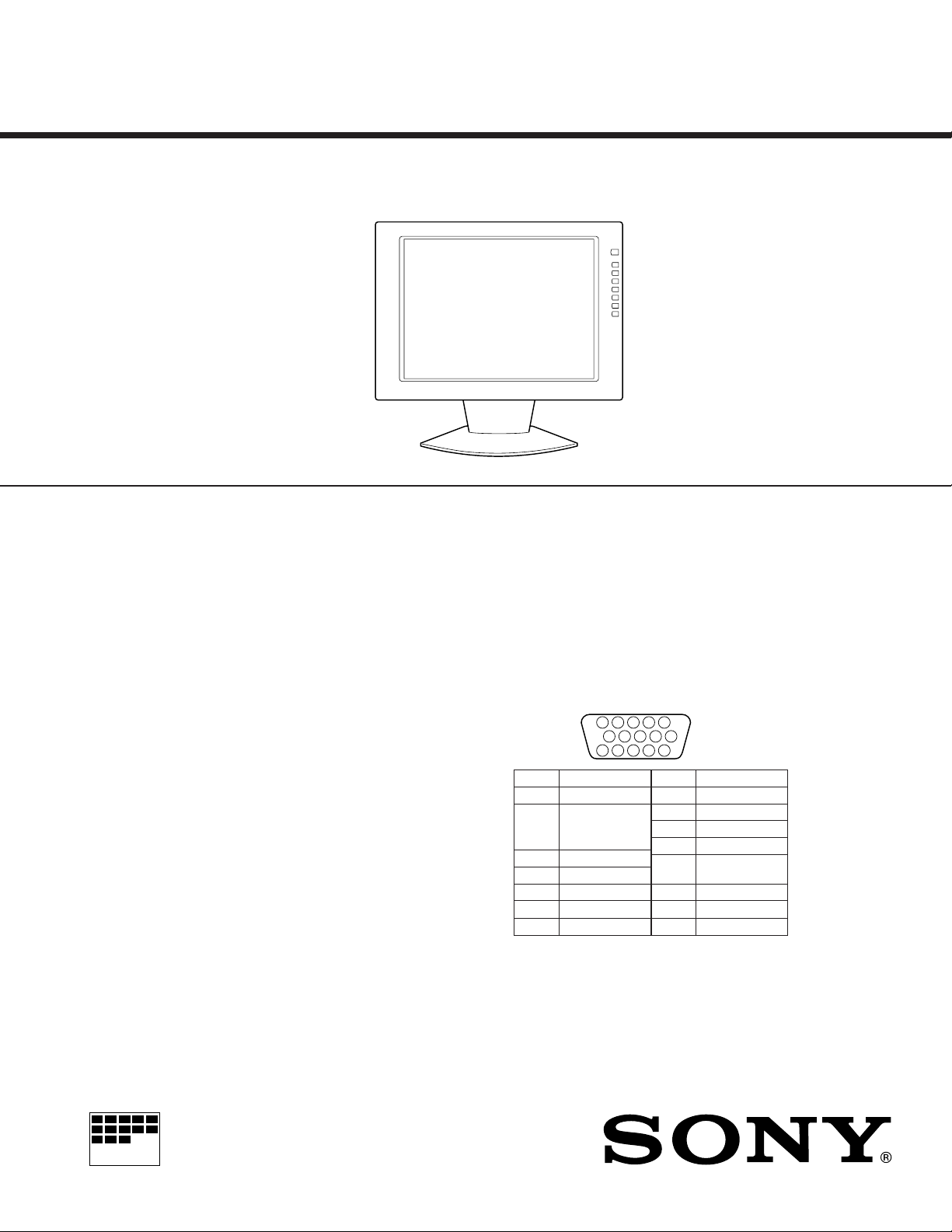
CPD-L181A
US Model
Canadian Model
AEP Model
Chassis No. SCC-G25E-A
LCD panel Panel type: a-Si TFT Active Matrix
Input signal format RGB operating frequency*
Pixel efficiency 99.99 %
Resolution H: max. 1280 dots
Power requirements Input:
Power consumption Monitor only: 3.0 A
AC adapter Type: AC-L181A
Dimensions (w/h/d) Including the stand:
Mass Approx. 9 kg (19 lb 14 oz)
Plug & Play DDC/DDC2B/DDC2Bi
Supplied accessories LCD monitor (1)
MICROFILM
Picture size: 18.1 inches (46 cm)
fh: 30 – 92 kHz
fv: 48 – 85 Hz
V: max. 1024 lines
Including the AC adapter: 0.7 A
Input rating:
Output rating: DC 20 V, 5 A
Monitor only:
Rear cover (1)
Power cord (1)
AC adapter (1)
HD15 video signal cable (1)
Macintosh adapter (1)
Windows
Disk/Utility Disk (1)
Macintosh Utility Disk (1)
Warranty card (1)
These operating instructions (1)
DC 20 V (using the AC adapter)
AC 100 – 240 V, 50 – 60 Hz
Max 1.2 A
Approx. 468 × 422 × 207.5 mm
1
/2 × 16 5/8 × 8 1/4 in.)
(18
Approx. 468 × 354.5 × 95 mm
1
/2 × 14 × 3 3/4 in.)
(18
including the stand
Monitor Information
TFT LCD COLOR COMPUTER DISPLAY
5 4 3 2
1
678910
1112131415
CPD-L181A
DIAGNOSIS
Failure Power LED
Aging Blink Amber (On 0.5 sec, Off 0.5 sec) .... Blink Green (On 0.5 sec, Off 0.5 sec)
Out of Scan Range On Green
*Aging mode ...........................................Press MENU key for longer than 5 second.
Power Saving Function
This monitor meets the power-saving guidelines set by
E
VESA and
NERGY STAR, as well as the more stringent
NUTEK .
If the monitor is connected to a computer or video graphics
board that is VESA DPMS (Display Power Management
Signaling) compliant, the monitor will automatically reduce
power consumption in three stages as shown below.
You can set the delay time before the monitor enters the
power saving mode using the OSD. Set the time according
to “Setting the Power Saving Delay Time” on page 1-6.
* Power consumption of the monitor only. The figures in
parentheses are power consumption of the monitor including
the AC adapter.
** “Sleep” and “deep sleep” are power saving modes defined by
the Environmental Protection Agency.
*** When your computer enters the power saving mode, the input
signal is cut and NO INPUT SIGNAL appears on the screen.
After the time set in “Changing the Power Saving Delay Time”
(page 1-6) has elapsed, the monitor enters the power saving
mode.
Power consumption
mode
Normal operation
1
Standby (1st mode)
2
Suspend (2nd mode)
3
(sleep)**
Active-off (3rd mode)***
4
(deep sleep)**
Power-off
5
Power
consumption*
≤ 65 W (≤ 75W)
≤ 1 W (≤ 5W)
≤ 1 W (≤ 5W)
≤ 1 W (≤ 5W)
≤ 1 W (≤ 5W)
u Indicator
Green
Green and orange
alternate
Green and orange
alternate
Orange
Off
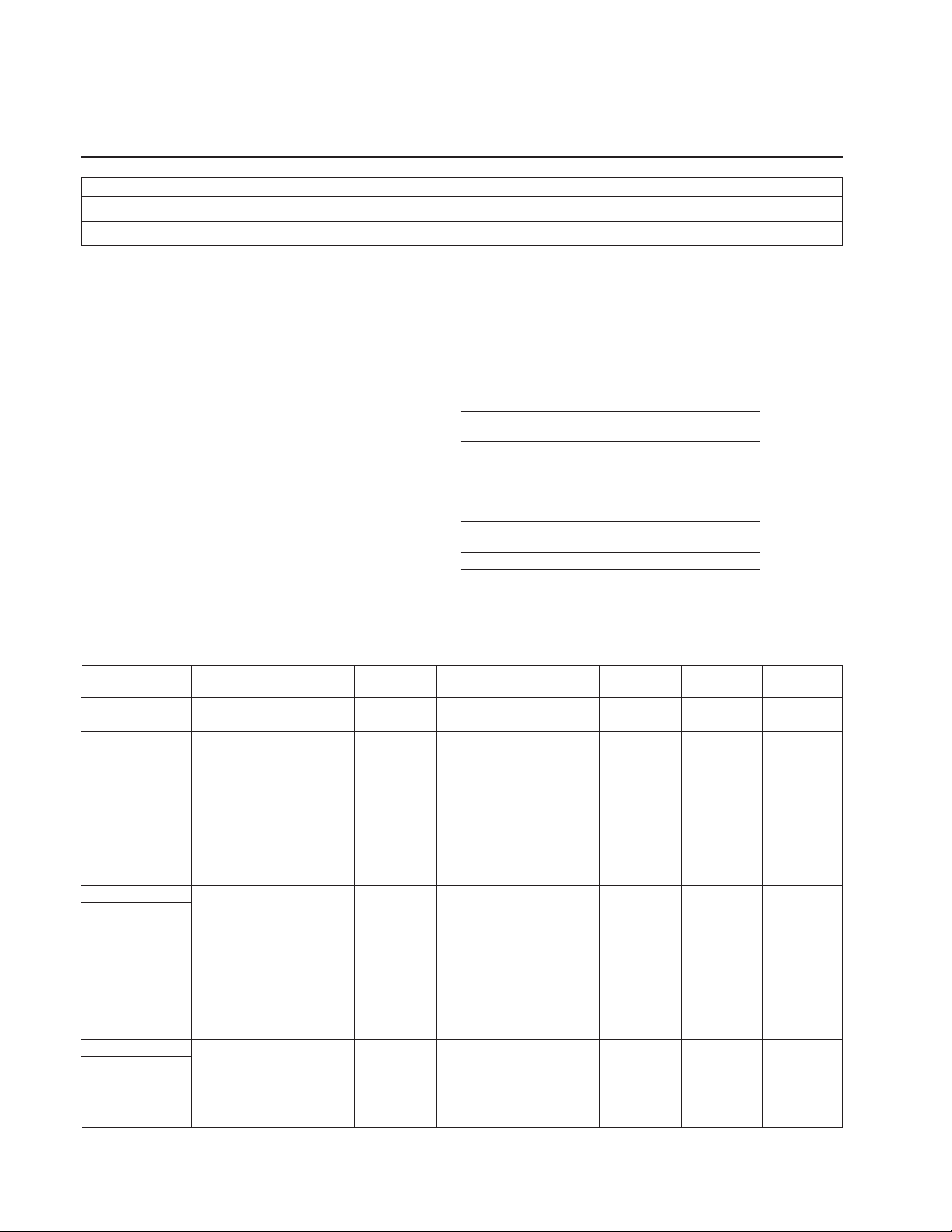
TIMING SPECIFICATION
PRIMARY MODE
MODE AT PRODUCTION
RESOLUTION 640 X 480 640 X 480 640 X 480 640 X 480 720 X 400 720 X 400 — 720 X 480
CLOCK 25.175 MHZ 30.240 MHZ 31.500 MHZ 36.000 MHZ 28.350 MHZ 35.500 MHZ — 31.505 MHZ
— HORIZONTAL —
H-FREQ 31.469 kHz 35.000 kHz 37.500 kHz 43.269 kHz 31.500 kHz 37.927 — 35.162 kHz
H. TOTAL 31.778 28.571 26.667 23.111 31.746 26.366 — 28.440
H. BLK 6.356 7.407 6.349 5.333 6.349 6.085 — 5.586
H. FP 0.636 2.116 0.508 1.556 0.635 1.014 — 1.079
H. SYNC 3.813 2.116 2.032 1.556 3.810 2.028 — 1.270
H. BP 1.907 3.175 3.810 2.222 1.905 3.042 — 3.238
H. ACTIV 25.422 21.164 20.317 17.778 25.397 20.282 — 22.854
— VERTICAL —
V. FREQ(HZ) 59.940 Hz 66.667 Hz 75.000 Hz 85.008 Hz 70.156 Hz 85.039 — 59.901 Hz
V. TOTAL 525 525 500 509 449 446 — 587
V. BLK 45 45 20 29 49 46 — 107
V. FP 10 3 1 1 12 1 — 12
V. SYNC 2 3 3 3 3 3 — 2
V. BP 33 39 16 25 34 42 — 93
V. ACTIV 480 480 480 480 400 400 — 480
— SYNC —
INT(G) NO NO NO NO NO NO — NO
EXT(H/V)/POLARITY YES N/N YES N/N YES N/N YES N/N YES N/P YES N/P — YES N/N
EXT(CS)/POLARITY NO NO NO NO NO NO — NO
INT/NON INT NON INT NON INT NON INT NON INT NON INT NON INT — NON INT
MODE 0 MODE 1 MODE 2 MODE 3 MODE 4 MODE 5 MODE 6 MODE 7
usec usec usec usec usec usec usec usec
lines lines lines lines lines lines lines lines
– 2 –
CPD-L181A
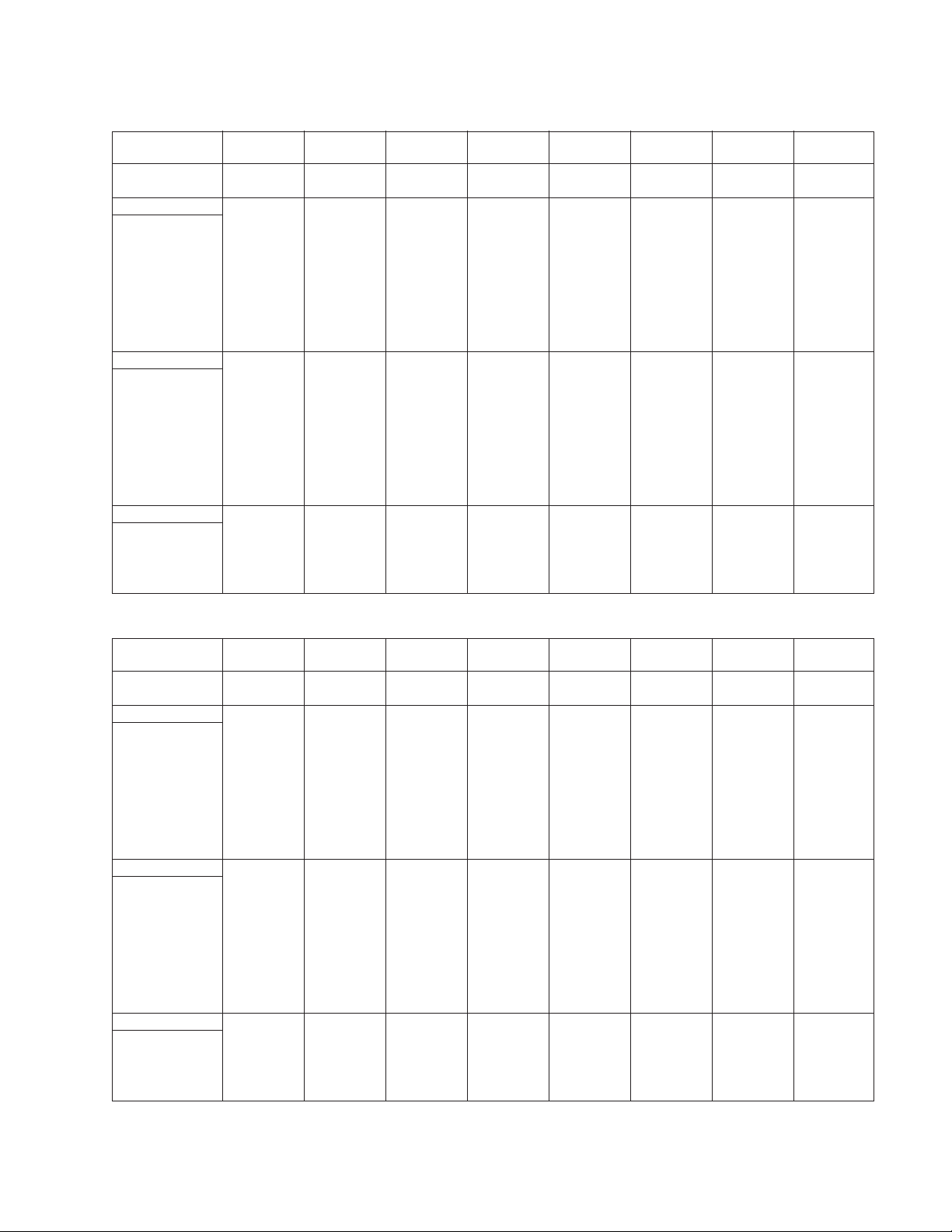
PRIMARY MODE
MODE AT PRODUCTION
RESOLUTION 800 X 600 800 X 600 800 X 600 800 X 600 800 X 600 848 X 480 832 X 624 1024 X 768
CLOCK 36.000 MHZ 40.000 MHZ 49.500 MHZ 56.250 MHZ 57.299 MHZ 49.847 MHZ 57.285 MHZ 65.000 MHZ
— HORIZONTAL —
H-FREQ 35.156 kHz 37.879 kHz 46.875 kHz 53.674 kHz 54.675 kHz 45.900 kHz 46.727 kHz 48.363 kHz
H. TOTAL 28.444 26.400 21.333 18.631 18.290 21.787 20.110 20.677
H. BLK 6.222 6.400 5.172 4.409 4.328 4.815 5.586 4.923
H. FP 0.667 1.000 0.323 0.569 0.558 1.083 0.559 0.369
H. SYNC 0.889 3.200 1.616 1.138 1.117 1.204 1.117 2.092
H. BP 4.667 2.200 3.232 2.702 2.653 2.488 3.910 2.462
H. ACTIV 22.222 20.000 16.162 14.222 13.962 17.012 14.524 15.754
— VERTICAL —
V. FREQ(HZ) 56.250 Hz 60.317 Hz 75.000 Hz 85.061 Hz 86.648 Hz 88.269 Hz 74.553 Hz 60.004 Hz
V. TOTAL 625 628 625 631 631 520 667 806
V. BLK 25 28 25 31 31 40 43 38
V. FP 1 1 1 1 1 9 3 3
V. SYNC 2 4 3 3 3 6 3 6
V. BP 22 23 21 27 27 25 37 29
V. ACTIV 600 600 600 600 600 480 624 768
— SYNC —
INT(G) NO NO NO NO NO NO NO NO
EXT(H/V)/POLARITY YES N/N YES P/P YES P/P YES P/P YES P/P YES P/P YES N/N YES N/N
EXT(CS)/POLARITY NO NO NO NO NO NO NO NO
INT/NON INT NON INT NON INT NON INT NON INT NON INT NON INT NON INT NON INT
MODE 8 MODE 9 MODE 10 MODE 11 MODE 12 MODE 13 MODE 14 MODE 15
usec usec usec usec usec usec usec usec
lines lines lines lines lines lines lines lines
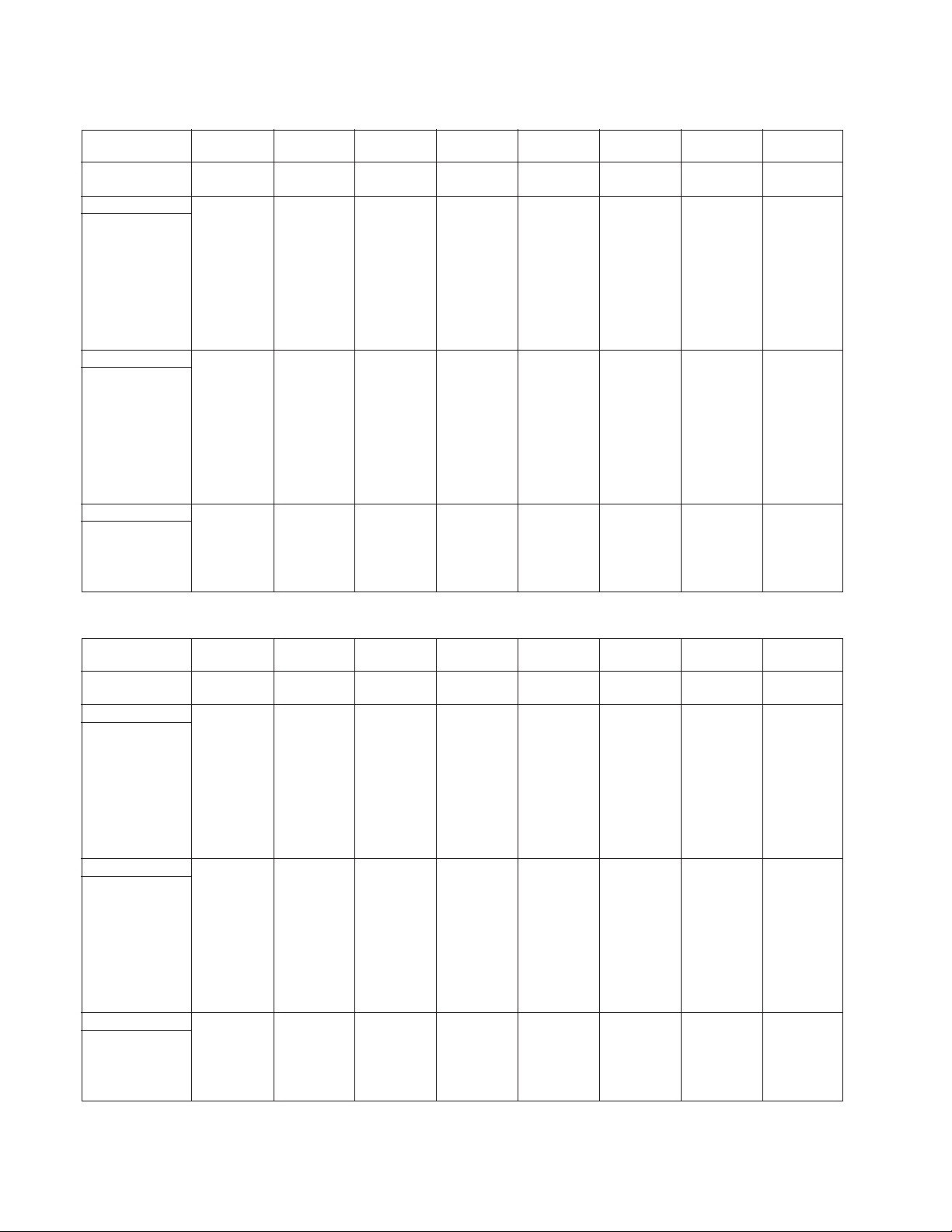
PRIMARY MODE
MODE AT PRODUCTION
RESOLUTION 1024 X 768 1024 X 768 1024 X 768 1152 X 864 1152 X 864 1152 X 870 1120 X 750 1152 X 900
CLOCK 75.000 MHZ 78.750 MHZ 94.500 MHZ 108.000 MHZ 121.500 MHZ 100.000 MHZ 78.430 MHZ 92.940 MHZ
— HORIZONTAL —
H-FREQ 56.476 kHz 60.023 kHz 68.677 kHz 67.500 kHz 77.487 kHz 68.681 kHz 50.019 kHz 61.795 kHz
H. TOTAL 17.707 16.660 14.561 14.815 12.905 14.560 19.992 16.182
H. BLK 4.053 3.657 3.725 4.148 3.424 3.040 5.712 3.787
H. FP 0.320 0.203 0.508 0.593 0.527 0.320 2.193 0.323
H. SYNC 1.813 1.219 1.016 1.185 1.053 1.280 1.428 1.377
H. BP 1.920 2.235 2.201 2.370 1.844 1.440 2.091 2.087
H. ACTIV 13.653 13.003 10.836 10.667 9.481 11.520 14.280 12.395
— VERTICAL —
V. FREQ(HZ) 70.069 Hz 75.029 Hz 84.997 Hz 75.000 Hz 85.057 Hz 75.062 Hz 60.047 Hz 65.950 Hz
V. TOTAL 806 800 808 900 911 915 833 937
V. BLK 38 32 40 36 47 45 83 37
V. FP 3 1 1 1 1 3 27 2
V. SYNC 6 3 3 3 3 3 10 4
V. BP 29 28 36 32 43 39 46 31
V. ACTIV 768 768 768 864 864 870 750 900
— SYNC —
INT(G) NO NO NO NO NO NO NO NO
EXT(H/V)/POLARITY YES N/N YES P/P YES P/P YES P/P NO P/P YES N/N YES N/N YES N/N
EXT(CS)/POLARITY NO NO NO NO NO NO NO NO
INT/NON INT NON INT NON INT NON INT NON INT NON INT NON INT NON INT NON INT
MODE 16 MODE 17 MODE 18 MODE 19 MODE 20 MODE 21 MODE 22 MODE 23
usec usec usec usec usec usec usec usec
lines lines lines lines lines lines lines lines
– 3 –
CPD-L181A
PRIMARY MODE
MODE AT PRODUCTION
RESOLUTION 1152 X 900 1170 X 584 1024 X 800 1280 X 960 1280 X 960 1280 X 1024 1280 X 1024 1280 X 1024
CLOCK 105.590 MHZ 46.200 MHZ 92.940 MHZ 108.000 MHZ 148.500 MHZ 108.000 MHZ 135.000 MHZ 157.500 MHZ
— HORIZONTAL —
H-FREQ 71.732 kHz 31.216 kHz 70.838 kHz 60.000 kHz 85.938 kHz 63.981 kHz 79.976 kHz 91.146 kHz
H. TOTAL 13.941 32.035 14.117 16.667 11.636 15.630 12.504 10.971
H. BLK 3.031 6.710 3.099 4.815 3.017 3.778 3.022 2.844
H. FP 0.152 0.801 0.258 0.889 0.431 0.444 0.119 0.406
H. SYNC 0.909 2.792 1.033 1.037 1.077 1.037 1.067 1.016
H. BP 1.970 3.117 1.808 2.889 1.508 2.296 1.837 1.422
H. ACTIV 10.910 25.325 11.018 11.852 8.620 11.852 9.481 8.127
— VERTICAL —
V. FREQ(HZ) 76.068 Hz 50.026 Hz 84.031 Hz 60.000 Hz 85.002 Hz 60.020 Hz 75.025 Hz 85.024 Hz
V. TOTAL 943 624 843 1000 1011 1066 1066 1072
V. BLK 43 40 43 40 51 42 42 48
V. FP 2 3 2 1 1 1 1 1
V. SYNC 8 3 8 3 3 3 3 3
V. BP 33 34 33 36 47 38 38 44
V. ACTIV 900 584 800 960 960 1024 1024 1024
— SYNC —
INT(G) NO NO NO NO NO NO NO NO
EXT(H/V)/POLARITY YES N/N YES N/N YES N/N YES P/P YES P/P YES P/P NO P/P YES P/P
EXT(CS)/POLARITY NO NO NO NO NO NO NO NO
INT/NON INT NON INT NON INT NON INT NON INT NON INT NON INT NON INT NON INT
MODE 24 MODE 25 MODE 26 MODE 27 MODE 28 MODE 29 MODE 30 MODE 31
usec usec usec usec usec usec usec usec
lines lines lines lines lines lines lines lines
PRIMARY MODE
MODE AT PRODUCTION
RESOLUTION 1280 X 1024 1024 X 768 — — 1280 X 1024 800X 600 1024 X 768 1280 X 1024
CLOCK 148.000 MHZ 80.000 MHZ — — 135.000 MHZ 50.000 MHZ 71.640 MHZ 100.000 MHZ
— HORIZONTAL —
H-FREQ 81.319 kHz 60.241 kHz — — 81.130 kHz 48.077 kHz 53.946 kHz 60.680 kHz
H. TOTAL 12.297 16.600 — — 12.326 20.800 18.537 16.480
H. BLK 3.649 3.800 — — 2.844 4.800 4.243 3.680
H. FP 0.270 0.400 — — 0.237 1.120 0.223 0.240
H. SYNC 1.378 1.200 — — 0.474 2.400 2.457 1.120
H. BP 2.000 2.200 — — 2.133 1.280 1.563 2.320
H. ACTIV 8.649 12.800 — — 9.481 16.000 14.294 12.800
— VERTICAL —
V. FREQ(HZ) 77.006 Hz 74.927 Hz — — 76.107 Hz 72.188 Hz 66.110 Hz 57.030 Hz
V. TOTAL 1056 804 — — 1066 666 816 1064
V. BLK 32 36 — — 42 66 48 40
V. FP 3 3 — — 2 37 8 3
V. SYNC 3 3 — — 8 6 4 3
V. BP 26 30 — — 32 23 36 34
V. ACTIV 1024 768 — — 1024 600 768 1024
— SYNC —
INT(G) YES NO — — NO NO NO NO
EXT(H/V)/POLARITY NO YES N/N — — YES N/N YES N/N YES N/N YES N/N
EXT(CS)/POLARITY NO NO — — NO NO NO NO
INT/NON INT NON INT NON INT — — NON INT NON INT NON INT NON INT
MODE 32 MODE 33 MODE 34 MODE 35 MODE 36 MODE 37 MODE 38 MODE 39
usec usec usec usec usec usec usec usec
lines lines lines lines lines lines lines lines
99.4.9 VER.
– 4 –
SAFETY CHECK-OUT
r
CPD-L181A
After correcting the original service problem, perform the following safety checks before releasing the set to the customer:
1. Check the area of your repair for unsoldered or poorly-soldered connections. Check the entire board surface for solder
splashes and bridges.
2. Check the interboard wiring to ensure that no wires are
“pinched” or contact high-wattage resistors.
3. Check that all control knobs, shields, covers, ground straps,
and mounting hardware have been replaced. Be absolutely
certain that you have replaced all the insulators.
4. Look for unauthorized replacement parts, particularly transistors, that were installed during a previous repair. Point
them out to the customer and recommend their replacement.
5. Look for parts which, though functioning, show obvious
signs of deterioration. Point them out to the customer and
recommend their replacement.
6. Check the line cords for cracks and abrasion. Recommend
the replacement of any such line cord to the customer.
7. Check the B+ and HV to see if they are specified values.
Make sure your instruments are accurate; be suspicious of
your HV meter if sets always have low HV.
8. Check the antenna terminals, metal trim, “metallized”
knobs, screws, and all other exposed metal parts for AC
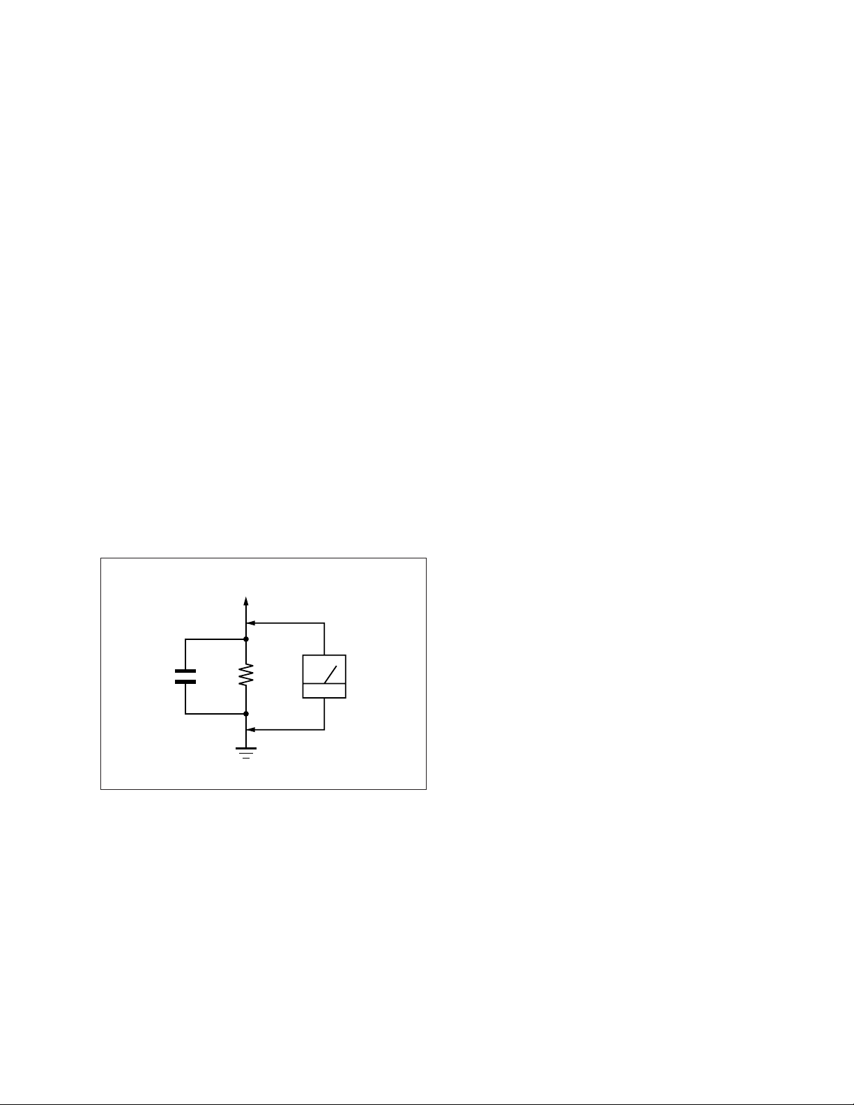
Leakage. Check leakage as described below.
To Exposed Metal
Parts on Set
0.15 µF
1.5 k
Ω
AC
Voltmete
(0.75 V)
LEAKAGE TEST
The AC leakage from any exposed metal part to earth ground
and from all exposed metal parts to any exposed metal part having a return to chassis, must not exceed 0.5 mA (500
microampers).
Leakage current can be measured by any one of three methods.
1. A commercial leakage tester, such as the Simpson 229 or
RCA WT-540A. Follow the manufacturers’ instructions to
use these instruments.
2. A battery-operated AC milliammeter. The Data Precision
245 digital multimeter is suitable for this job.
3. Measuring the voltage drop across a resistor by means of a
VOM or battery-operated AC voltmeter. The “limit” indication is 0.75 V, so analog meters must have an accurate lowvoltage scale. The Simpson 250 and Sanwa SH-63Trd are
examples of a passive VOMs that are suitable. Nearly all
battery operated digital multimeters that have a 2 V AC
range are suitable. (See Fig. A)
WARNING!!
NEVER TURN ON THE POWER IN A CONDITION IN
WHICH THE DEGAUSS COIL HAS BEEN REMOVED.
SAFETY-RELATED COMPONENT WARNING!!
COMPONENTS IDENTIFIED BY SHADING AND MARK
¡ ON THE SCHEMATIC DIAGRAMS, EXPLODED
VIEWS AND IN THE PARTS LIST ARE CRITICAL FOR
SAFE OPERATION. REPLACE THESE COMPONENTS
WITH SONY PARTS WHOSE PART NUMBERS APPEAR AS SHOWN IN THIS MANUAL OR IN SUPPLEMENTS PUBLISHED BY SONY. CIRCUIT ADJUSTMENTS THAT ARE CRITICAL FOR SAFE OPERATION
ARE IDENTIFIED IN THIS MANUAL. FOLLOW THESE
PROCEDURES WHENEVER CRITICAL COMPONENTS
ARE REPLACED OR IMPROPER OPERATION IS SUSPECTED.
Earth Ground
Fig. A. Using an AC voltmeter to check AC leakage.
AVERTISSEMENT!!
NE JAMAIS METTRE SOUS TENSION QUAND LA
BOBINE DE DEMAGNETISATION EST ENLEVÉE.
ATTENTION AUX COMPOSANTS RELATIFS À LA
SÉCURITÉ!!
LES COMPOSANTS IDENTIFIÉS PAR UNE TRAME ET
UNE MARQUE
¡ SONT CRITIQUES POUR LA SÉCURITÉ.
NE LES REMPLACER QUE PAR UNE PIÈCE PORTANT LE
NUMÉRO SPECIFIÉ. LES RÉGLAGES DE CIRCUIT DONT
L’IMPORTANCE EST CRITIQUE POUR LA SÉCURITÉ DU
FONCTIONNEMENT SONT IDENTIFIÉS DANS LE
PRÉSENT MANUEL. SUIVRE CES PROCÉDURES LORS
DE CHAQUE REMPLACEMENT DE COMPOSANTS CRITIQUES, OU LORSQU’UN MAUVAIS FONCTIONNEMENT
EST SUSPECTÉ.
– 5 –

CPD-L181A
TABLE OF CONTENTS
Section Title Page
1. GENERAL .................................................................. 1-1
2. DISASSEMBLY
2-1. Cabinet Assy, Shield and Holder J Removal ...... 2-1
2-2. J Board Removal .................................................. 2-1
2-3. A Board and GA Board Removal ....................... 2-2
2-4. Liquid Crystal Panel Module
and H Board Removal .......................................... 2-2
3. ADJUSTMENTS ...................................................... 3-1
4. DIAGRAMS
4-1. Block Diagrams .................................................... 4-1
4-2. Frame Schematic Diagram ................................... 4-7
4-3. Circuit Boards Location ...................................... 4-9
4-4. Schematic Diagrams and Printed Wiring Boards ... 4-9
(1) Schematic Diagram of J Board ............................ 4-10
(2) Schematic Diagram of H Board ........................... 4-11
(3) Schematic Diagram of A (P1-P8) Board ............. 4-13
(4) Schematic Diagram of GA Board ........................ 4-29
4-5. Semiconductors ................................................... 4-35
5. EXPLODED VIEWS
5-1. Chassis ................................................................. 5-1
5-2. Packing Materials ................................................ 5-2
6. ELECTRICAL PARTS LIST ............................ 6-1
– 6 –
The operating instructions mentioned here are partial abstracts
from the Operating Instruction Manual. The page numbers of
the Operating Instruction Manual remein as in the manual.
4
Getting Started
Precautions
Installation
• Prevent internal heat build-up by allowing adequate air
circulation. Do not place the monitor on surfaces (rugs,
blankets, etc.) or near materials (curtains, draperies) that
may block the ventilation holes.
• Do not install the monitor near heat sources such as
radiators or air ducts, or in a place subject to direct
sunlight, excessive dust, mechanical vibration or shock.
• Do not place the monitor near equipment which generates
magnetism, such as a transformer or high voltage power
lines.
Handling the LCD screen
• Bright points of light (red, blue or green) may appear
on the LCD screen. This is not a malfunction. The LCD
screen is made with high-precision technology and
more than 99.99 % of the picture element is intact.
However, some of the picture element may not
appear or some of the picture element may appear
constantly.
• Do not leave the LCD screen facing the sun as it can
damage the LCD screen. Take care when you place the
monitor by a window.
• Do not push or scratch the LCD screen. Do not place a
heavy object on the LCD screen. This may cause the
screen to lose uniformity.
• If the monitor is used in a cold place, a residual image
may appear on the screen. This is not a malfunction.
When the monitor becomes warm, the screen returns to
normal.
• If a still picture is displayed for a long time, a residual
image may appear. The residual image will eventually
disappear.
• The screen and the cabinet become warm during
operation. This is not a malfunction.
About the fluorescent tube
A specially designed fluorescent tube is installed as the
lighting apparatus for this monitor. If the LCD screen
becomes dark, unstable or does not turn on, consult your
Sony dealer.
Getting Started
for 100 to 120 V AC for 200 to 240 V AC
for 240 V AC only
Maintenance
• Clean the cabinet, panel and controls with a soft cloth
lightly moistened with a mild detergent solution. Do not
use any type of abrasive pad, scouring powder or solvent,
such as alcohol or benzine.
• Do not rub, touch, or tap the surface of the screen with
sharp or abrasive items such as a ballpoint pen or
screwdriver. This type of contact may result in a scratched
picture tube.
• Clean the screen with a soft cloth. If you use a glass
cleaning liquid, do not use any type of cleaner
containing an antistatic solution or similar additive as this
may scratch the screen’s coating.
Transportation
• When you transport this monitor, grip the bottom of the
screen firmly with both hands. If you drop the monitor,
you may be injured or the monitor may be damaged.
• When you transport this monitor for repair or shipment,
use the original carton and packing materials.
Warning on power connection
• Use an appropriate power cord for your local power
supply.
For the customers in the U.S.A.
If you do not use the appropriate cord, this monitor will
not conform to mandatory FCC standards.
For the customers in the UK
If you use the monitor in the UK, please use the supplied
UK cable with the UK plug.
Examples of plug types
The outlet should be installed near the equipment
and be easily accessible.
Disposal of the monitor
• Do not dispose of the monitor with general waste.
Do not include the monitor with household waste.
• The fluorescent tube includes mercury. Dispose of the
monitor in accordance with the regulations of your
local sanitation authority.
5
Getting Started
Getting Started
F
D
ES
GB
I
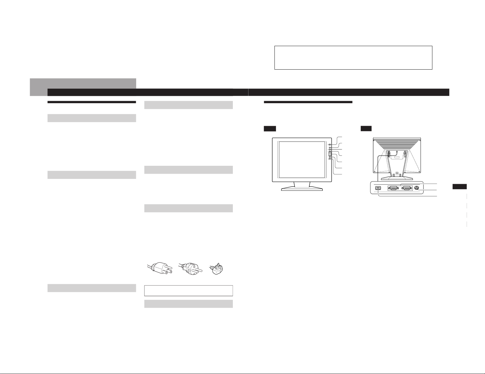
Identifying Parts and Controls
See the pages in parentheses for further details.
Front
1 u (power) switch and indicator (pages 8,
17)
Turns the monitor on or off.
The indicator lights up in green when the monitor is
turned on, and either flashes in green and orange or
lights up in orange when the monitor is in power
saving mode.
2 MENU (menu) button (pages 9 – 16, 19)
Displays the MENU OSD (On-Screen Display).
3 ¨ (brightness) (˘) button (pages 9 – 16)
Adjusts the picture brightness.
Functions as the ˘ button when selecting menu items.
4 > (contrast) (≥) button (pages 9 – 16)
Adjusts the contrast.
Functions as the ≥ button when selecting menu items.
5 +/– (adjust) buttons (pages 11 – 16)
Adjusts the selected menu item.
6 AUTO button (page 10)
When the signal from the computer is displayed on this
monitor, press the AUTO button to automatically adjust
the picture to the computer.
You also should press this button if the picture is not
centered or if it is fuzzy.
Rear
7 …1, 2 input switch and indicator (page 8)
Selects the input signal from …1 or …2. Each time you
press the button, the input changes and the
corresponding indicator lights up.
8 …1/…2 input connectors (HD15) (pages 6,
8)
Input analog RGB video signals (0.714 Vp-p, positive)
and SYNC signals.
9 DC IN connector (page 6)
Provides DC power to the monitor from the AC
adaptor.
* This connector is used by service personnel only. Do not
connect anything to this outlet.
1
2
3
4
5
6
7
AUTO
MENU
8
9
SECTION 1
GENERAL
1-1
6
Getting Started
IBM PC/AT or
compatible
computer
HD15 video
signal cable
(supplied)
to monitor output
to …1 or …2
HD15 video
signal cable
(supplied)
Setup
Before using this monitor, check that the following items are
included in your carton:
• LCD monitor (1)
• Rear cover (1)
• Power cord (1)
• AC adapter (1)
• HD15 video signal cable (1)
• Macintosh adapter (1)
• Windows
Monitor Information Disk/Utility Disk (1)
• Macintosh Utility Disk (1)
• Warranty card (1)
• These operating instructions (1)
Step 1: Connect the monitor to the
computer
Turn off the monitor and computer before connecting.
Connecting to an IBM PC/AT or compatible
computer
If your PC system is not compatible with Plug &
Play (DDC2B and DDC2Bi)
This monitor uses the No. 9 pin in the video signal connector for
Plug & Play (DDC2B and DDC2Bi) compatibility. See page 20 for
the location of the No. 9 pin.
• If your computer accepts the No. 9 pin, use the supplied HD15
video signal cable.
• If your computer does not accept the No. 9 pin, please consult
your dealer for advice on obtaining an HD15 adapter.
to monitor output
Connecting to a Macintosh
Use the supplied Macintosh adapter.
* Connect the supplied Macintosh adapter to the computer before
connecting the cable. This adapter is compatible with Macintosh
LC, Performa, Quadra, Power Macintosh and Power Macintosh
G3 series computers (sold before January, 1999). If you are
connecting to a Power Macintosh G3 series that sold after
January 1999, you will need a different adapter (not supplied).
Macintosh II series and some older versions of PowerBook
models may need an adapter with micro switches (not
supplied).
Step 2: Connect the power cord
With the monitor and computer switched off, connect one
end of the power cord to the AC power adapter, and the AC
power adaptor to the monitor. Then connect the other end
of the power cord to a power outlet.
to …1 or …2
Macintosh adapter
(supplied)*
Macintosh or
compatible computer
to a power outlet
Power cord
(supplied)
to DC IN
AC power
adapter
(supplied)
7
Getting Started
Getting Started
F
D
ES
GB
I
1
2
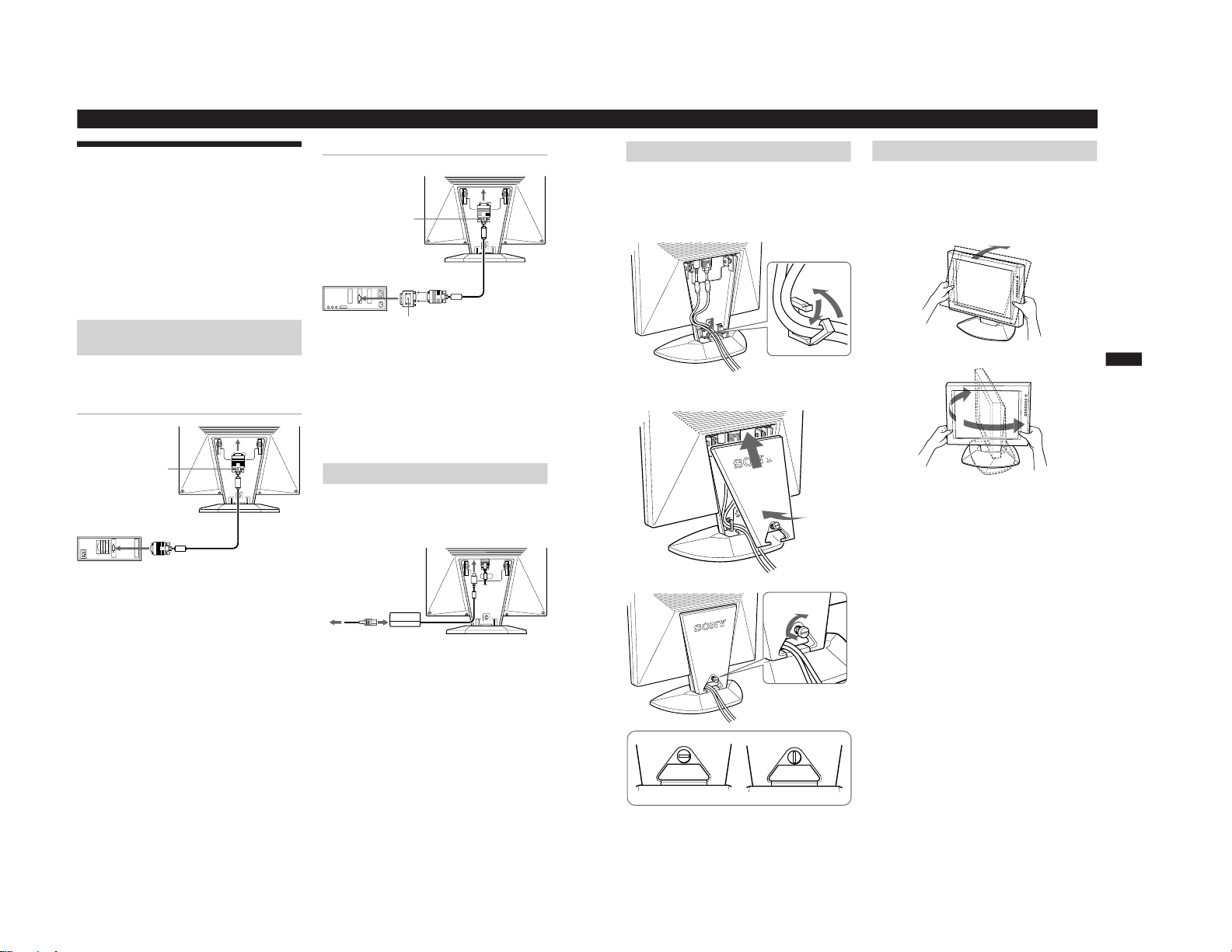
Step 3: Attaching the rear cover
After connecting the computer and power cord, attach the
supplied rear cover.
Make sure that you keep the screen upright when attaching
the rear cover.
1
Hook the computer cable and power cord.
2
Press the top of the rear cover against the top of the
part for attaching the cover, and then push the rear
cover in.
3
Turn the screw to fasten the rear cover.
Unlocked
Locked
Use of the Tilt
The tilt feature will adjust the monitor within 30° upward,
and 45° to the left or right. However, best viewing results
can be obtained by tilting the screen upward by 5° or more.
To turn the monitor, hold at the bottom with both hands as
illustrated below.
30°
45°
45°
1-2
8
Getting Started
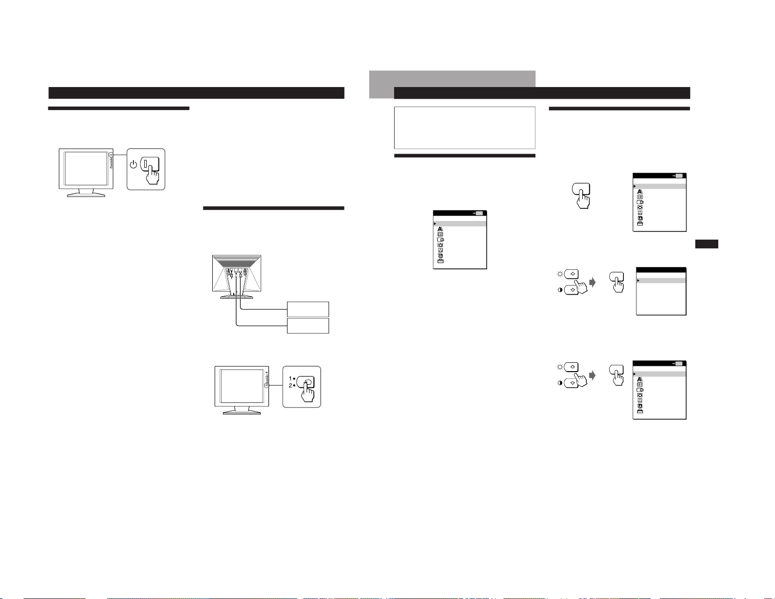
Turning on the Monitor and
Computer
1
Press the u switch.
2
Turn on the computer.
The installation of your monitor is complete.
If necessary, use the monitor’s controls to adjust the picture.
If no picture appears on your screen
• Check that the monitor is correctly connected to the computer.
• If NO INPUT SIGNAL appears on the screen, try changing the
input signal, and confirm that your computer’s graphics board is
completely seated in the correct bus slot.
• If you are replacing an old monitor with this model and OUT OF
SCAN RANGE appears on the screen, reconnect the old
monitor. Then adjust the computer’s graphics board so that the
horizontal frequency is between 30 – 92 kHz, the vertical
frequency is between 40 – 85 Hz, and the resolution is 1280 x
1024 or lower.
For more information about the on-screen messages, see “Trouble
symptoms and remedies” on page 18.
For customers using Windows 95/98
To maximize the potential of your monitor, install the new model
information file from the supplied Windows Monitor Information
Disk/Utility Disk onto your PC.
This monitor complies with the “VESA
DDC” Plug & Play standard.
If your PC/graphics board complies with DDC, select “Plug & Play
Monitor (VESA DDC)” or this monitor’s model name as the
monitor type in the “Control Panel” of Windows 95/98. If your
PC/graphics board has difficulty communicating with this monitor,
load the Windows Monitor Information Disk/Utility Disk and
select this monitor’s model name as the monitor type.
For customers using Windows NT4.0
Monitor setup in Windows NT4.0 is different from Windows 95/98
and does not involve the selection of monitor type. Refer to the
Windows NT4.0 instruction manual for further details on adjusting
the resolution, refresh rate, and number of colors.
Adjusting the monitor’s resolution and color number
Adjust the monitor’s resolution and color number by referring to
your computer’s instruction manual. The color number may vary
according to your computer or graphics board. The color palette
setting and the actual number of colors are as follows:
• High color (16 bit) n 65,536 colors.
• True Color (24 bit) n about 16.77 million colors
In true color mode (24 bit), speed may be slower.
Selecting the Input Signal
You can connect two computers to this monitor using the
HD 15 connectors. To switch between the two computers,
use the … button.
Press the … button.
The input signal and corresponding input indicator change
each time you press this button.
Note
If you restart the computer you want to view, or that computer is in
power saving mode, the monitor may automatically switch to the
other connector’s signal. If this happens, manually select the
desired signal using the … button.
Computers
connected to
…2
connected to
…1
9
Getting Started
Customizing Your Monitor
F
D
ES
GB
I
Customizing Your Monitor
Before adjusting
Connect the monitor and the computer, and turn them
on.
Wait for at least 30 minutes before making adjustments
for the best result.
Introducing the On-Screen
Display System
Most adjustments are made using the MENU OSD.
To change the on-screen display language, see “Selecting
the On-Screen Display Language.”
EXIT
Closes the MENU OSD.
PHASE
Displays the PHASE OSD. Adjust the phase when the
characters or pictures appear fuzzy throughout the entire
screen. Adjust the phase after adjusting the pitch.
PITCH
Displays the PITCH OSD. Adjust the pitch when the
characters or pictures are not clear at some parts of the
screen.
CENTER
Displays the CENTER OSD for adjusting the centering of
the picture.
ZOOM/SMOOTHING
Displays the ZOOM/SMOOTHING OSD for adjusting the
picture’s sharpness according to the input signal’s aspect
ratio or resolution.
COLOR
Displays the COLOR OSD for adjusting the color
temperature.
LANGUAGE
Displays the LANGUAGE OSD for selecting the on-screen
display language.
OPTION
Displays the OPTION OSD. You can adjust settings such as
the backlight, OSD position, power saving delay time and
control lock.
MENU
EXIT
PHASE
PITCH
CENTER
ZOOM/SMOOTHING
COLOR
LANGUAGE
OPTION
MENU
OK
MENU
MENU
EXIT
PHASE
PITCH
CENTER
ZOOM/SMOOTHING
COLOR
LANGUAGE
OPTION
MENU
OK
MENU
LANGUAGE
ENGLISH
FRANÇAIS
DEUTSCH
ESPAÑOL
ITALIANO
œ{Œ
MENU
Selecting the On-Screen Display
Language
You can select the OSD language from English, French,
German, Spanish, Italian, and Japanese.
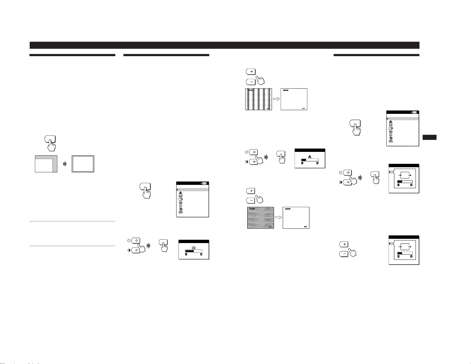
1
Press the MENU button.
The MENU OSD appears.
2
Press the ˘/≥ buttons to select LANGUAGE, and
press the MENU button.
The LANGUAGE OSD appears.
3
Press the ˘/≥ buttons to select the desired language,
and press the MENU button.
The MENU OSD of the selected language appears.
The OSD automatically disappears after about 30 seconds.
To close the OSD, press the MENU button again.
MENU
EXIT
PHASE
PITCH
CENTER
ZOOM/SMOOTHING
COLOR
LANGUAGE
OPTION
MENU
OK
1-3
Customizing Your Monitor
10
Automatically Adjusting the
Picture
If the picture is flickering or fuzzy, press the AUTO button.
The monitor is automatically adjusted to match the signal
from the connected computer.
Further fine adjustments may be needed with some
computers. In this case, manually adjust the monitor.
1
Turn on the monitor.
2
Turn on the computer.
3
Press the AUTO button.
The monitor adjusts the pitch to match the input signal
so that the picture appears sharp, and fits the picture to
the center of the screen.
Notes
• This function is intended for use with a computer running
Windows or similar graphic user interface software that
provides a full-screen picture. It may not work properly if the
background color is dark or if the input picture does not fill the
screen to the edges (such as an MS-DOS prompt).
• The screen may go blank for a few seconds while performing the
auto-sizing function. This is not a malfunction.
If the picture is flickering or fuzzy even after you
press the AUTO button
Adjust the Pitch and Phase by referring to “Eliminating
Flickering or Blurring Manually.”
If the picture is not in the center of the screen
even after you press the AUTO button
Adjust using the CENTER OSD by referring to “Adjusting
the Picture Position.”
AUTO
Eliminating Flickering or Blurring
Manually
If a part of the screen is flickering or blurring, press the
AUTO button. If this operation does not work, adjust the
Pitch and Phase as follows.
Once the pitch and phase are adjusted, they will be stored in
memory for the current input signal.
1
Set the resolution to 1280 × 1024 on the computer.
If the resolution of the graphics board is lower than 1280
× 1024, set ZOOM to REAL (page 12).
2
Load the Utility Disk.
Use the appropriate disk for your computer.
For Windows 95/98
Windows Monitor Information Disk/Utility Disk
For Macintosh
Macintosh Utility Disk
3
Start the Utility Disk and display the test pattern.
For Windows 95/98
Click [Utility Disk] n [Windows] n [Utility.exe].
For Macintosh
Click [Utility Disk] n [SONY-Utility].
4
Press the MENU button.
The MENU OSD appears.
5
Press the ˘/≥ buttons to select PITCH, and press the
MENU button again.
The PITCH OSD appears.
MENU
EXIT
PHASE
PITCH
CENTER
ZOOM/SMOOTHING
COLOR
LANGUAGE
OPTION
MENU
OK
MENU
MENU
PITCH
0
11
Getting Started
Customizing Your Monitor
F
D
ES
GB
I
MENU
6
Press the +/– buttons until the screen color becomes
uniform.
Adjust so that the vertical stripes disappear.
7
Press the MENU button.
The MENU OSD appears.
If horizontal stripes are observed over the entire screen,
adjust the Phase in the next step.
8
Press the ˘/≥ buttons to select PHASE, and press the
MENU button again.
The PHASE OSD appears.
9
Press the +/– buttons until the screen color becomes
uniform.
Adjust until the horizontal stripes are at a minimum.
10
When you have finished, click [END] on the screen to
turn off the test pattern.
The OSD automatically disappears after about 30 seconds.
To close the OSD, press the MENU button twice.
MENU
EXIT
PHASE
PITCH
CENTER
ZOOM/SMOOTHING
COLOR
LANGUAGE
OPTION
MENU
OK
MENU
Adjusting the Picture Position
If the picture is not in the center of the screen, press the
AUTO button. If this operation does not work, adjust the
centering as follows.
Once the centering is adjusted, it will be stored in memory
for the current input signal.
1
Start the Utility Disk and display the test pattern.
Do steps 2 and 3 of “Eliminating Flickering or Blurring
Manually.”
2
Press the MENU button.
The MENU OSD appears.
3
Press the ˘/≥ buttons to select CENTER, and press
the MENU button again.
The CENTER OSD appears.
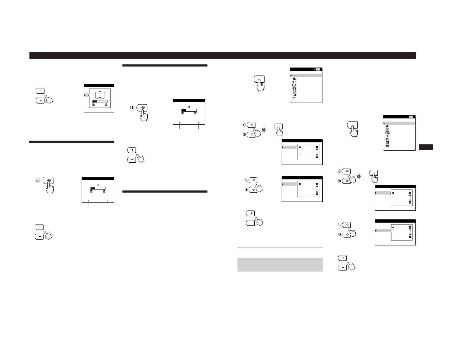
4
Move the picture up, down, left, or right until the
frame at the perimeter of the test pattern
disappears.
For horizontal adjustment, select H using the ˘/≥
buttons and adjust the position using the +/–
buttons.
+ . . . to move the picture right
– . . . to move the picture left
Continued
PHASE
4
MENU
CENTER
H
V
26
CENTER
H
V
26
1-4
Customizing Your Monitor
12
Horizontal
Frequency*
Vertical
Frequency*
BRIGHTNESS
26
48. 4kHz / 60Hz
CONTRAST
26
48. 4kHz / 60Hz
Horizontal
Frequency*
Vertical
Frequency*
For vertical adjustment, select V using the ˘/≥
buttons and adjust the position using the +/–
buttons.
+ . . . to move the picture up
– . . . to move the picture down
5
When you have finished, click [END] on the screen to
turn off the test pattern.
The OSD automatically disappears after about 30 seconds.
To close the OSD, press the MENU button twice.
Adjusting the Picture Brightness
Once the brightness is adjusted, it will be stored in memory
for all input signals received.
1
Press the ¨ (brightness) ˘ button.
The BRIGHTNESS OSD appears.
2
Press the +/– buttons.
+ . . . for more brightness
– . . . for less brightness
The OSD automatically disappears after about 3 seconds.
* The horizontal and vertical frequencies for the received input
signal appear in the BRIGHTNESS OSD.
If the screen is too bright when using the monitor in a
dark room
Decrease the BACKLIGHT (page 15).
CENTER
H
V
26
Adjusting the Contrast
Once the contrast is adjusted, it will be stored in memory for
all input signals received.
1
Press the > (contrast) ≥ button.
The CONTRAST OSD appears.
2
Press the +/– buttons.
+. . . for more contrast
– . . . for less contrast
The OSD automatically disappears after about 3 seconds.
* The horizontal and vertical frequencies for the received input
signal appear in the CONTRAST OSD.
Changing the Picture Size
According to the Signal
The monitor is set at the factory to display the picture on the
screen in full, irrespective of the picture’s mode or
resolution. You can also view the picture at its actual aspect
ratio or resolution. Note that 1280 × 1024 resolution signals
fill the entire screen and ZOOM is not possible.
Once the zoom is set, it will be stored in memory for the
current input signal.
FULL 1
The input signal is displayed on the screen in full,
irrespective of the picture’s mode or resolution.
FULL 2
The input signal is displayed on the screen at its actual
aspect ratio. Therefore, black bands may appear at the
top and bottom of the picture depending on the signal.
REAL
The input signal is displayed on the screen at its actual
resolution. (Sub-SXGA signals are displayed at the center
of the screen surrounded by black frame.)
13
Getting Started
Customizing Your Monitor
F
D
ES
GB
I
MENU
EXIT
PHASE
PITCH
CENTER
ZOOM/SMOOTHING
COLOR
LANGUAGE
OPTION
MENU
OK
MENU
MENU
ZOOM/SMOOTHING
ZOOM
SMOOTHING
FULL1
FULL2
REAL
1
Press the MENU button.
The MENU OSD appears.
2
Press the ˘/≥ buttons to select ZOOM/SMOOTHING,
and press the MENU button again.
The ZOOM/SMOOTHING OSD appears.
3
Press the ˘/≥ buttons to select ZOOM.
4
Press the +/– buttons to select the desired mode.
The OSD automatically disappears after about 30 seconds.
To close the OSD, press the MENU button twice.
To display the picture on the screen in full
Select “FULL 1” in step 4.
If the picture displayed at FULL 1 or FULL2
mode is not smooth
Use the picture smoothing function. The smoothing effect
becomes stronger in the order of TEXT n STANDARD n
GRAPHICS. Note that 1280 × 1024 resolution signals are
shown only in REAL mode and SMOOTHING is not
possible.
Once the smoothing is set, it will be stored in memory for
the current input signal.
STANDARD
Standard smoothing effect (factory preset smoothing
effect).
TEXT
To make the characters appear clear. (This mode is suited
for text-based applications.)
GRAPHICS
To make the pictures appear clean. (This mode is suited
for CD-ROM software such as photo images or
illustrations.)
1
Press the MENU button.
The MENU OSD appears.
2
Press the ˘/≥ buttons to select ZOOM/SMOOTHING,
and press the MENU button again.
The ZOOM/SMOOTHING OSD appears.
3
Press the ˘/≥ buttons to select SMOOTHING.
4
Press the +/– buttons to select the desired mode.
The OSD automatically disappears after about 30 seconds.
To close the OSD, press the MENU button twice.
MENU
MENU
EXIT
PHASE
PITCH
CENTER
ZOOM/SMOOTHING
COLOR
LANGUAGE
OPTION
MENU
OK
MENU
ZOOM/SMOOTHING
ZOOM
SMOOTHING
FULL1
FULL2
REAL
ZOOM/SMOOTHING
ZOOM
SMOOTHING
FULL1
FULL2
REAL
ZOOM/SMOOTHING
ZOOM
SMOOTHING
STANDARD
TEXT
GRAPHICS
1-5
Customizing Your Monitor
14
COLOR
9300K
6500K
5000K
USER MODE
R
G
B
50
50
50
MENU
To adjust the vertical
position
OPTION
: 5SEC
: UNLOCK
OSD H POSITION
MENU
EXIT
PHASE
PITCH
CENTER
ZOOM/SMOOTHING
COLOR
LANGUAGE
OPTION
MENU
OK
MENU
MENU
COLOR
9300K
6500K
5000K
USER MODE
R
G
B
50
50
50
Changing or Adjusting the Color
Temperature
The color temperature is set to 9300K at the factory.
You can change the color temperature to 6500K or 5000K.
Use this function to adjust the color temperature so that it
matches the actual colors of a printed picture.
Once the color temperature is adjusted, it will be stored in
memory for all input signals received.
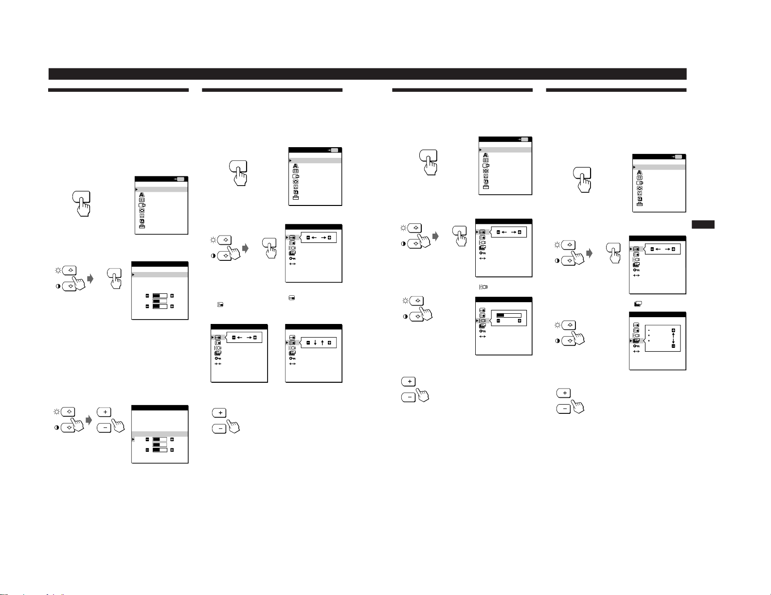
1
Press the MENU button.
The MENU OSD appears.
2
Press the ˘/≥ buttons to select COLOR, and press the
MENU button again.
The COLOR OSD appears.
3
Press the ˘/≥ buttons to select the color
temperature.
If you need to make further adjustments to the selected
color temperature, go to step 4.
If you don’t, press the MENU button. The MENU OSD
appears.
4
Press the ˘/≥ buttons to select R (red) or B (blue),
and press the +/– buttons to get the desired color.
The color changes as the R or B components increase or
decrease with respect to G (green).
The OSD automatically disappears after about 30 seconds.
To close the OSD, press the MENU button twice.
Changing the On-Screen Display
Position
You can change the OSD position (for example, when you
want to adjust the picture behind the OSD).
1
Press the MENU button.
The MENU OSD appears.
2
Press the ˘/≥ buttons to select OPTION, and press
the MENU button again.
The OPTION OSD appears.
3
Press the ˘/≥ buttons to select
(OSD H POSITION)
or
(OSD V POSITION).
To adjust the horizontal
position
4
Press the +/– buttons to move the OSD to the desired
position.
The OPTION OSD automatically disappears after about 30
seconds.
To close the OSD, press the MENU button twice.
MENU
EXIT
PHASE
PITCH
CENTER
ZOOM/SMOOTHING
COLOR
LANGUAGE
OPTION
MENU
OK
MENU
OPTION
: 5SEC
: UNLOCK
OSD H POSITION
OPTION
: 5SEC
: UNLOCK
OSD V POSITION
15
Getting Started
Customizing Your Monitor
F
D
ES
GB
I
OPTION
26
: UNLOCK
BACKLIGHT
Setting the Power Saving Delay
Time
You can set the delay time before the monitor enters the
power saving mode. See page 17 for more information on
this monitor’s power saving capabilities.
1
Press the MENU button.
The MENU OSD appears.
2
Press the ˘/≥ buttons to select OPTION, and press
the MENU button again.
The OPTION OSD appears.
3
Press the ˘/≥ buttons to select
ZZ...
(PWR SAVE
DELAY).
4
Press the +/– buttons to select the desired time.
When PWR SAVE DELAY is set to OFF, the monitor
does not go into power saving mode.
The OPTION OSD automatically disappears after about 30
seconds.
To close the OSD, press the MENU button twice.
Adjusting the Backlight
If the screen is too bright when you are using the monitor in
a dark room, adjust the backlight.
1
Press the MENU button.
The MENU OSD appears.
2
Press the ˘/≥ buttons to select OPTION, and press
the MENU button again.
The OPTION OSD appears.
3
Press the ˘/≥ buttons to select
(BACKLIGHT).
4
Press the +/– buttons to adjust the light level.
The OPTION OSD automatically disappears after about 30
seconds.
To close the OSD, press the MENU button twice.
OPTION
60MIN
1MIN
5SEC
OFF
PWR SAVE DELAY
MENU
MENU
EXIT
PHASE
PITCH
CENTER
ZOOM/SMOOTHING
COLOR
LANGUAGE
OPTION
MENU
OK
OPTION
: 5SEC
: UNLOCK
OSD H POSITION
MENU
MENU
MENU
EXIT
PHASE
PITCH
CENTER
ZOOM/SMOOTHING
COLOR
LANGUAGE
OPTION
MENU
OK
OPTION
: 5SEC
: UNLOCK
OSD H POSITION
MENU
1-6
Customizing Your Monitor
16
Locking the Controls
The control lock function disables all of the controls except
the u (power) switch, MENU and some other buttons on
the front panel.
Once you select “LOCK,” you can select only the following
items in the MENU OSD:
• EXIT
• CONTROL LOCK and FACTORY PRESET in the
OPTION OSD
If you press any locked button, the
mark appears on
the screen.
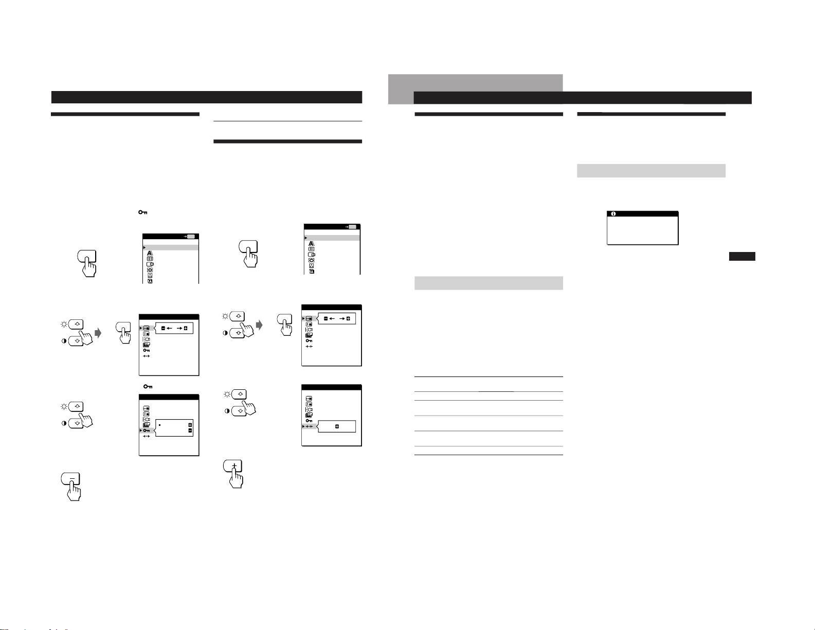
1
Press the MENU button.
The MENU OSD appears.
2
Press the ˘/≥ buttons to select OPTION, and press
the MENU button again.
The OPTION OSD appears.
3
Press the ˘/≥ buttons to select
(CONTROL
LOCK).
4
Press the – button to select LOCK.
The OPTION OSD automatically disappears after about 30
seconds.
To close the OSD, press the MENU button twice.
MENU
MENU
OPTION
: 5SEC
: UNLOCK
OSD H POSITION
OPTION
UNLOCK
LOCK
CONTROL LOCK
OPTION
: 5SEC
ON
FACTORY PRESET
MENU
MENU
OPTION
: 5SEC
: UNLOCK
OSD H POSITION
To cancel the control lock
Press the + button in step 4 to select UNLOCK.
Resetting the Adjustments
You can reset all of the adjustments and settings to the
factory settings.
The color temperature is reset to 9300K, the zoom setting is
reset to FULL 1 mode, and the power saving delay time is
reset to 5 seconds. The control lock is cancelled. All other
adjustments return to the default settings. The on-screen
language, however, does not change.
1
Press the MENU button.
The MENU OSD appears.
2
Press the ˘/≥ buttons to select OPTION, and press
the MENU button again.
The OPTION OSD appears.
3
Press the ˘/≥ buttons to select ? (FACTORY
PRESET).
4
Press the + button.
The OPTION OSD automatically disappears after about 30
seconds.
To close the OSD, press the MENU button twice.
MENU
EXIT
PHASE
PITCH
CENTER
ZOOM/SMOOTHING
COLOR
LANGUAGE
MENU
OK
MENU
EXIT
PHASE
PITCH
CENTER
ZOOM/SMOOTHING
COLOR
LANGUAGE
MENU
OK
17
Getting Started
Additional Information
F
D
ES
GB
I
Additional Information
Additional Information
Preset and User Modes
This monitor has factory preset modes for the most popular
industry standards for true “plug and play” compatibility.
(See Appendix for a list of the factory preset modes.)
When a new input signal is entered, the monitor selects the
appropriate factory preset mode and momentarily adjusts
the phase calibration to provide a high quality picture to the
center of the screen. The calibration is stored in memory
and is immediately recalled whenever the same input signal
is received.
For input signals that do not match one of the factory preset
modes, the digital Multiscan technology of this monitor
performs all of the adjustments necessary to ensure that a
clear picture appears on the screen for any timing in the
monitor’s frequency range. However, it may be necessary
to fine tune the vertical/horizontal centering. Simply press
the AUTO button or adjust the monitor according to the
adjustment instructions. The adjustments are stored
automatically as a user mode and recalled whenever the
corresponding input signal is received.
Power Saving Function
This monitor meets the power-saving guidelines set by
VESA and
E
NERGY STAR, as well as the more stringent
NUTEK .
If the monitor is connected to a computer or video graphics
board that is VESA DPMS (Display Power Management
Signaling) compliant, the monitor will automatically reduce
power consumption in three stages as shown below.
You can set the delay time before the monitor enters the
power saving mode using the OSD. Set the time according
to “Setting the Power Saving Delay Time” on page 15.
* Power consumption of the monitor only. The figures in
parentheses are power consumption of the monitor including
the AC adapter.
** “Sleep” and “deep sleep” are power saving modes defined by
the Environmental Protection Agency.
*** When your computer enters the power saving mode, the input
signal is cut and NO INPUT SIGNAL appears on the screen.
After the time set in “Changing the Power Saving Delay Time”
(page 15) has elapsed, the monitor enters the power saving
mode.
Troubleshooting
This section may help you isolate the cause of a problem
and as a result, eliminate the need to contact technical
support.
On-screen messages
If there is something wrong with the input signal, one of the
following messages appears on the screen. To solve the
problem, see “Trouble symptoms and remedies” on page 18.
“OUT OF SCAN RANGE” indicates that the input signal is
not supported by the monitor’s specifications.
“NO INPUT SIGNAL” indicates that no signal is input to the
monitor.
INFORMATION
OUT OF SCAN RANGE
Power consumption
mode
Normal operation
Standby (1st mode)
Suspend (2nd mode)
(sleep)**
Active-off (3rd mode)***
(deep sleep)**
Power-off
Power
consumption*
≤ 65 W (≤ 75 W)
≤ 1 W (≤ 5 W)
≤ 1 W (≤ 5 W)
≤ 1 W (≤ 5 W)
≤ 1 W (≤ 5 W)
u Indicator
Green
Green and orange
alternate
Green and orange
alternate
Orange
Off
1
2
3
4
5
1-7
18
Additional Information
Trouble symptoms and remedies
If the problem is caused by the connected computer or other equipment, please refer to the connected equipment’s instruction
manual.
Use the self-diagnosis function (page 19) if the following recommendations do no resolve the problem.
Symptom Check these items
No picture
If the u indicator is not lit
If the “NO INPUT SIGNAL”
message appears on the screen,
or if the u indicator is either
orange or alternating between
green and orange
If the “OUT OF SCAN RANGE”
message appears on the screen
If no message is displayed and
the u indicator is green or
flashing orange
If using Windows 95/98
If using a Macintosh system
Picture flickers, bounces,
oscillates, or is scrambled.
Picture is fuzzy.
Picture is dark.
• Check that the power cord is properly connected.
• Check that the u (power) switch is in the “on” position.
• Check that the video signal cable is properly connected and all plugs are firmly seated in
their sockets.
• Check that the input select setting is correct.
• Check that the HD15 video input connector’s pins are not bent or pushed in.
pProblems caused by the connected computer or other equipment
• The computer is in power saving mode. Try pressing any key on the computer keyboard.
• Check that the computer’s power is “on.”
• Check that your graphics board is completely seated in the proper bus slot.
pProblems caused by the connected computer or other equipment
• Check that the video frequency range is within that specified for the monitor. If you
replaced an old monitor with this monitor, reconnect the old monitor and adjust the
frequency range to the following.
Horizontal: 30 – 92 kHz, Vertical: 48 – 85 Hz
• Use the self-diagnosis function (page 19).
• If you replaced an old monitor with this monitor, reconnect the old monitor and do the
following. Install the Windows Monitor Information Disk/Utility Disk and select “CPDL181/L181A” from among the Sony monitors in the Windows 95/98 monitor selection
screen.
• Check that the Macintosh adapter and the video signal cable are properly connected
(page 6).
• Press the AUTO button. If this does not work, adjust the pitch and phase (page 10).
• Isolate and eliminate any potential sources of electric or magnetic fields such as other
monitors, laser printers, electric fans, fluorescent lighting, or televisions.
• Move the monitor away from power lines or place a magnetic shield near the monitor.
• Try plugging the monitor into a different AC outlet, preferably on a different circuit.
• Try turning the monitor 90° to the left or right.
pProblems caused by the connected computer or other equipment
• Check your graphics board manual for the proper monitor setting.
• Confirm that the graphics mode (VESA, Macintosh 21” Color, etc.) and the frequency of
the input signal are supported by this monitor (Appendix). Even if the frequency is
within the proper range, some graphics boards may have a sync pulse that is too narrow
for the monitor to sync correctly.
• Adjust the computer’s refresh rate (vertical frequency) to obtain the best possible picture.
• Press the AUTO button. If this does not work, adjust the pitch and phase (page 10).
• Adjust the contrast and brightness (page 12).
• Adjust the backlight (page 15)
• Adjust the brightness (page 12).
• It takes several seconds for the monitor to warm up after the power is turned on. The
picture will appear momentarily.
19
Getting Started
Additional Information
F
D
ES
GB
I
Additional Information
Symptom Check these items
Picture appears to be ghosting.
Picture is not centered or sized
properly.
Wavy or elliptical (moire)
pattern is visible.
Color is not uniform.
White does not look white.
Monitor buttons do not
operate.
• Eliminate the use of video cable extensions and/or video switch boxes.
• Check that all plugs are firmly seated in their sockets.
• Press the AUTO button (page 10).
• Adjust the size (page 12) or centering (page 11). Note that some video modes do not fill
the screen to the edges.
• Adjust the pitch and phase (page 10).
• Press the AUTO button. If this does not work, adjust the pitch and phase (page 10).
• Adjust the color temperature (page 14).
• If the control lock is set to LOCK, set it to UNLOCK (page 16).
Self-diagnosis function
This monitor is equipped with a self-diagnosis function. If
there is a problem with your monitor or computer(s), the
screen will go blank and the u (power) indicator will either
light up green or flash orange. If the u (power) indicator is
lit in orange, the computer is in power saving mode. Try
pressing any key on the keyboard.
If the u (power) indicator is green
1
Disconnect the video signal cable(s).
2
Before the monitor goes to power saving mode,
press the + button and keep it pressed for 2 seconds.
If all four color bars appear (white, red, green, blue), the
monitor is working properly. Reconnect the video signal
cable(s) and check the condition of your computer(s).
If the color bars do not appear, there is a potential monitor
failure. Inform your authorized Sony dealer of the
monitor’s condition.
If the u (power) indicator is flashing
orange
Press the u (power) button to turn the monitor off and
on.
If the u (power) indicator lights up green, the monitor is
working properly.
If the u (power) indicator is still flashing, there is a
potential monitor failure. Count the number of seconds
between orange flashes of the u (power) indicator and
inform your authorized Sony dealer of the monitor’s
condition. Be sure to note the model name and serial
number of your monitor. Also note the make and model of
your computer and graphics board.
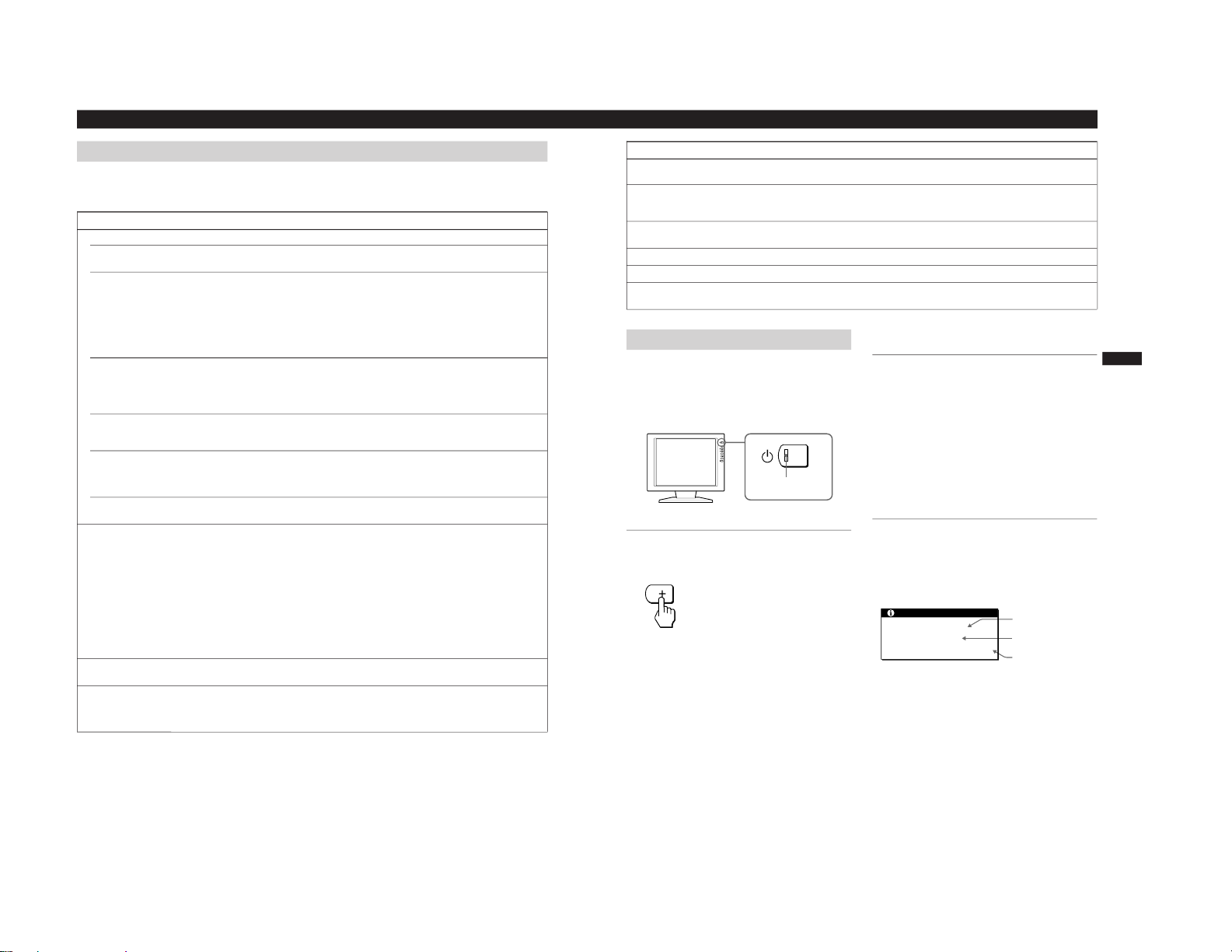
Displaying the INFORMATION OSD
You can confirm the name, the serial number and the year
of manufacture of this monitor.
Press and hold the MENU button for 5 seconds.
The INFORMATION OSD appears.
Example
u (power)
indicator
Model name
Serial number
Week and year of
manufacture
INFORMATION
MODEL : CPD-L181A
SER NO : 1234567
MANUFACTURED : 1999-52
1-8

SECTION 2
DISASSEMBLY
2-1. CABINET ASSY, SHIELD AND HOLDER J REMOVAL
1
Six screws
(+BVTP 4 x 16)
2
Cabinet assy
6
Seven screws
7
Shield (J)
(+BVTT 3 x 6)
4
Two screws
(+BVTT 3 x 6)
3
Ten screws
(+BVTT 3 x 6)
CPD-L181A
9
Holder, J
2-2. J BOARD REMOVAL
Holder, J
8
Two screws
(+BVTT 3 x 6)
CN302
5
Shield(A)
1
Four spacer(small)
3
J board
2-1
2
Two screws
(+BVTT 3 x 6)
 Loading...