

Sony CPD-4403 Service manual
CPD-4403
SERVICE MANUAL
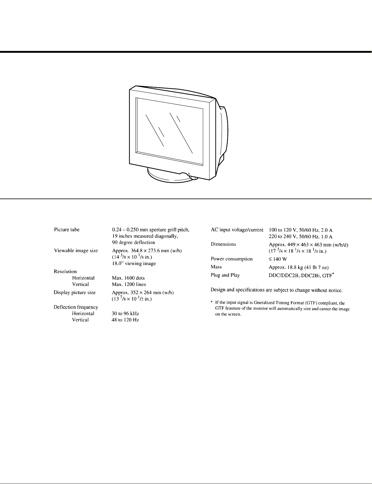
SPECIFICATIONS
AEP Model
Chassis No. SCC-L30N-A
(OEM STD)
Chassis No. SCC-L30Q-A
(ELSA, FORMAC)
F99
CHASSIS
TRINITRON
®
COLOR COMPUTER DISPLAY
CPD-4403
SAFETY CHECK-OUT
After correcting the original service problem, perform the following safety checks before releasing the set to the customer:
1. Check the area of your repair for unsoldered or poorly-soldered connections. Check the entire board surface for solder
splashes and bridges.
2. Check the interboard wiring to ensure that no wires are
“pinched” or contact high-wattage resistors.
3. Check that all control knobs, shields, covers, ground straps,
and mounting hardware have been replaced. Be absolutely
certain that you have replaced all the insulators.
4. Look for unauthorized replacement parts, particularly transistors, that were installed during a previous repair. Point
them out to the customer and recommend their replacement.
5. Look for parts which, though functioning, show obvious
signs of deterioration. Point them out to the customer and
recommend their replacement.
6. Check the line cords for cracks and abrasion. Recommend
the replacement of any such line cord to the customer.
7. Check the B+ and HV to see if they are specified values.
Make sure your instruments are accurate; be suspicious of
your HV meter if sets always have low HV.
8. Check the antenna terminals, metal trim, “metallized”
knobs, screws, and all other exposed metal parts for AC
Leakage. Check leakage as described below.
To Exposed Metal
Parts on Set
0.15 µF
1.5 k
Ω
AC
Voltmeter
(0.75 V)
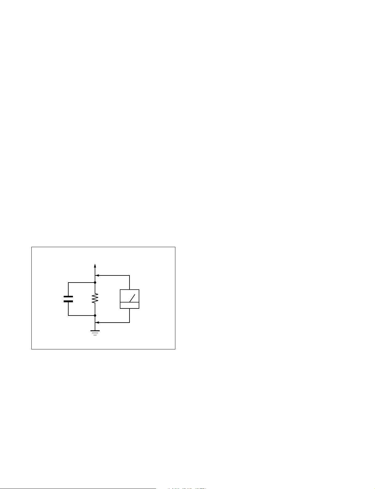
LEAKAGE TEST
The AC leakage from any exposed metal part to earth ground
and from all exposed metal parts to any exposed metal part having a return to chassis, must not exceed 0.5 mA (500 microamperes).
Leakage current can be measured by any one of three methods.
1. A commercial leakage tester, such as the Simpson 229 or
RCA WT-540A. Follow the manufacturers’ instructions to
use these instruments.
2. A battery-operated AC milliammeter. The Data Precision
245 digital multimeter is suitable for this job.
3. Measuring the voltage drop across a resistor by means of a
VOM or battery-operated AC voltmeter. The “limit” indication is 0.75 V, so analog meters must have an accurate lowvoltage scale. The Simpson 250 and Sanwa SH-63Trd are
examples of a passive VOMs that are suitable. Nearly all
battery operated digital multimeters that have a 2 V AC
range are suitable. (See Fig. A)
WARNING!!
NEVER TURN ON THE POWER IN A CONDITION IN
WHICH THE DEGAUSS COIL HAS BEEN REMOVED.
SAFETY-RELATED COMPONENT WARNING!!
COMPONENTS IDENTIFIED BY SHADING AND MARK
¡ ON THE SCHEMATIC DIAGRAMS, EXPLODED
VIEWS AND IN THE PARTS LIST ARE CRITICAL FOR
SAFE OPERATION. REPLACE THESE COMPONENTS
WITH SONY PARTS WHOSE PART NUMBERS APPEAR AS SHOWN IN THIS MANUAL OR IN SUPPLEMENTS PUBLISHED BY SONY. CIRCUIT ADJUSTMENTS THAT ARE CRITICAL FOR SAFE OPERATION
ARE IDENTIFIED IN THIS MANUAL. FOLLOW THESE
PROCEDURES WHENEVER CRITICAL COMPONENTS
ARE REPLACED OR IMPROPER OPERATION IS SUSPECTED.
Earth Ground
Fig. A. Using an AC voltmeter to check AC leakage.
– 2 –
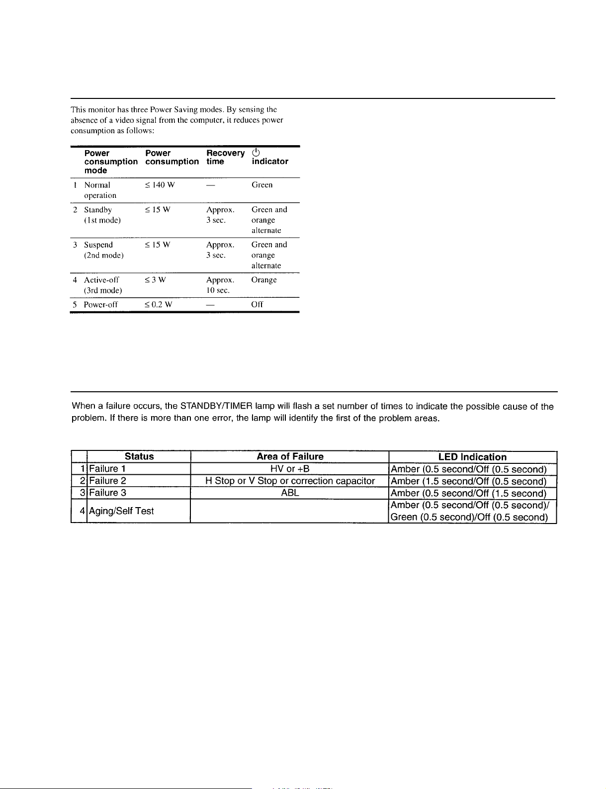
POWER SAVING FUNCTION
CPD-4403
DIAGNOSIS
– 3 –
CPD-4403
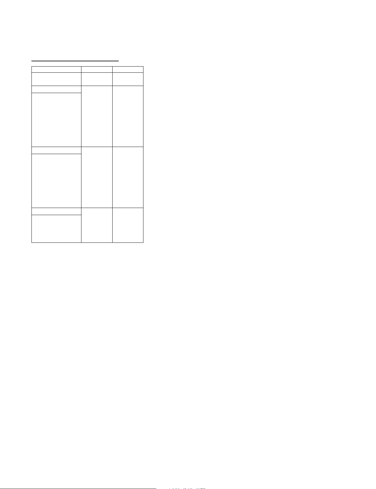
TIMING SPECIFICATION
MODE AT PRODUCTION MODE 1 MODE 2
RESOLUTION 738 X 414 1600 X 1200
CLOCK 28.322 MHz 202.500 MHz
HORIZONTAL
H-FREQ 31.469 kHz 93.750 kHz
usec usec
H. TOTAL 31.777 10.667
H. BLK 5.720 2.765
H. FP 0.318 0.316
H. SYNC 3.813 0.948
H. BP 1.589 1.501
H. ACTIV 26.057 7.901
– VERTICAL –
V. FREQ(HZ) 70.087 Hz 75.000 Hz
lines lines
V. TOTAL 449 1250
V. BLK 35 50
V. FP 5 1
V. SYNC 2 3
V. BP 28 46
V. ACTIV 414 1200
– SYNC –
INT(G) NO NO
EXT(H/V)/POLARITY YES N/P YES P/P
EXT(CS) /POLARITY NO NO
INT/NON INT NON INT NON INT
99.10.26 VER.
– 4 –

TABLE OF CONTENTS
Section Title Page
1. GENERAL ................................................................. 1-1
2. DISASSEMBLY
2-1. Cabinet Removal ................................................ 2-1
2-2. Shield (EMI, Video),
Side Cover (L and R) Removal.......................... 2-1
2-3. A Board Removal ............................................... 2-2
2-4. Rear Shield Complete Assy,
D Board Removal ............................................... 2-2
2-5. Service Position .................................................. 2-3
2-6. H Board Removal ............................................... 2-3
2-7. Picture Tube Removal........................................ 2-4
2-8. Harness Location ................................................ 2-5
3. SAFETY RELATED ADJUSTMENT............. 3-1
CPD-4403
4. ADJUSTMENTS ..................................................... 4-1
5. DIAGRAMS
5-1. Block Diagrams .................................................. 5-1
5-2. Frame Schematic Diagram ................................. 5-5
5-3. Circuit Boards Location ..................................... 5-6
5-4. Schematic Diagrams and Printed Wiring
Boards ................................................................. 5-7
(1) Schematic Diagram of A Board......................... 5-9
(2) Schematic Diagrams of D (a,b,c) Board.... 5-11
(3) Schematic Diagrams of N, H Boards................. 5-19
5-5. Semiconductors .................................................. 5-21
6. EXPLODED VIEWS
6-1. Chassis ................................................................ 6-1
6-2. Picture Tube........................................................ 6-2
6-3. Packing Materials ............................................... 6-3
7. ELECTRICAL PARTS LIST ............................ 7-1
– 5 –

1-1
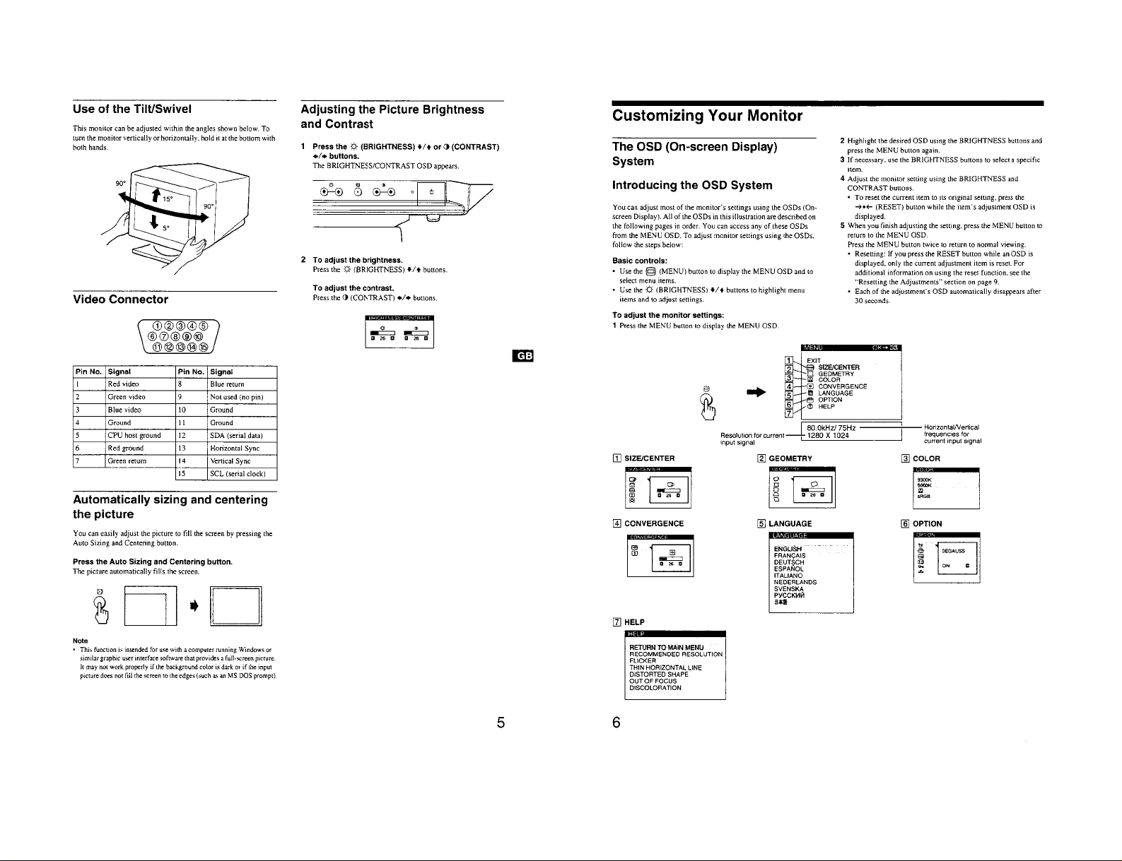
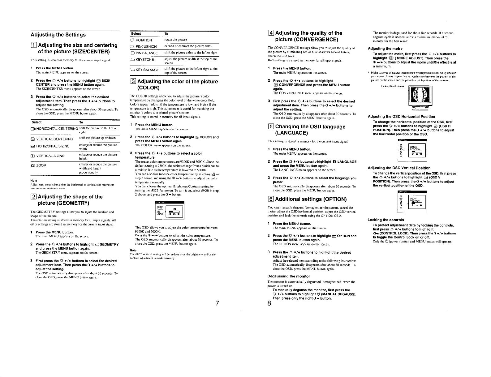
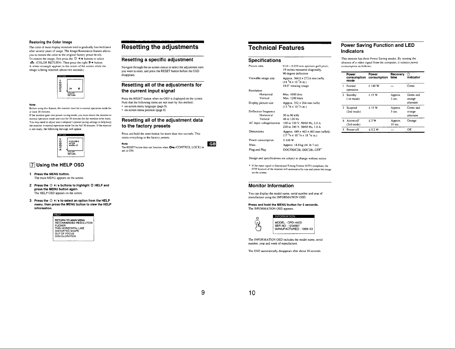
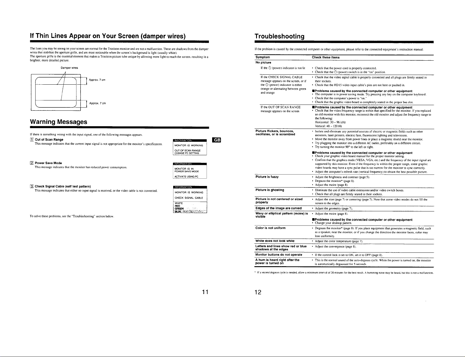
The operating instructions mentioned here are partial abstracts
from the Operating Instruction Manual. The page numbers of
the Operating Instruction Manual remain as in the manual.
SECTION 1
GENERAL
1-2
1-3
1-4
1-5
SECTION 2
DISASSEMBLY
CPD-4403
2-1. CABINET REMOVAL
Push in the tip of a screwdriver about
5mm to unlock the two claws.
Cabinet
Bezel assembly
Bezel assembly
Cabinet
1
Two claws
1
Two claws
3
Cabinet
2
Two screws
(+BVTP 4 x 16)
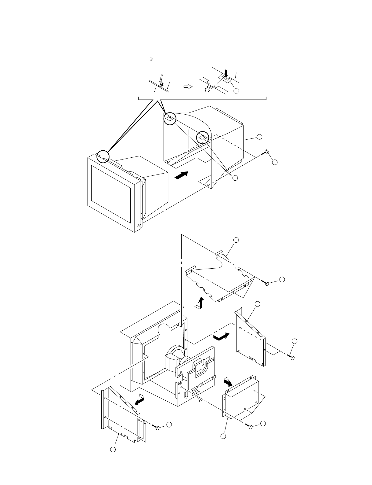
2-2. SHIELD (EMI, VIDEO),
SIDE COVER (L and R) REMOVAL
2
EMI shield (Upper)
4
Side cover (L)
1
Three screws
(+BVTT 4 x 8)
3
Two screws
(+BVTT 4 x 8)
6
Side cover (R)
5
Four screws
(+BVTT 4 x 8)
2-1
8
Video shield
7
Three screws
(+BVTT 4 x 8)
CPD-4403
2-3. A BOARD REMOVAL
CN303
CN309
CN306
CN311
CN305
4
A board
1
Screw
(+BVTT 4 x 8)
2
Cable stopper
3
Three screws
(+BVTT 3 x 8)
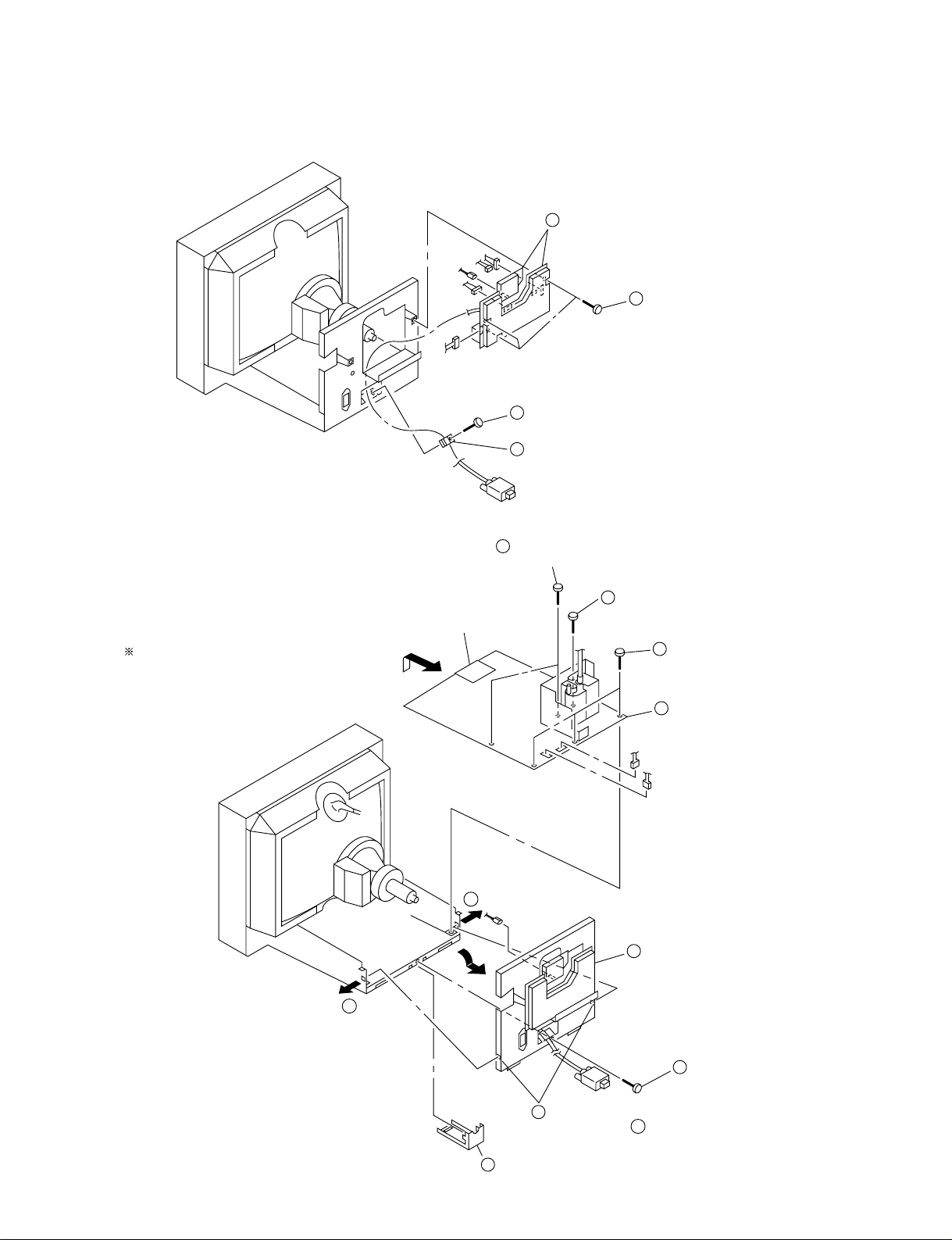
2-4. REAR SHIELD COMPLETE ASSY,
D BOARD REMOVAL
Refering to 2-3, disconnect five connectors
(CN303, CN305, CN306, CN309 and CN311).
N board
A
7
Two screws
(+BVTP 3 x 8)
CN303
6
Screw
(+P 3.5 x 20)
5
Three screws
(+BVTT 3 x 8)
8
D board
CN601
CN600
4
Rear shield
complete assembly
A
2
Screw
(+BVTT 4 x 8)
3
Widening the chassis toward
the direction A , disengage
two claws.
1
Cable cover
2-2
2-5. SERVICE POSITION
1
CPD-4403
A board
3
D board
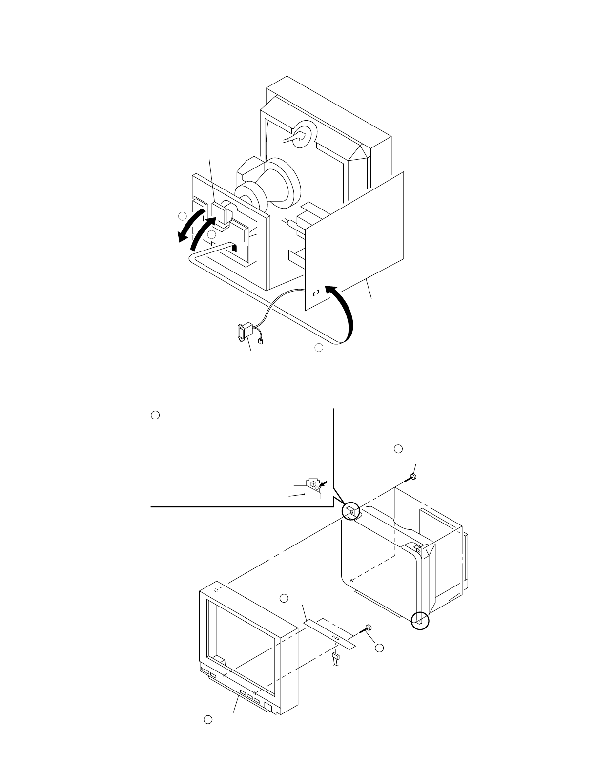
2-6. H BOARD REMOVAL
1
Before removing the bezel assembly,
secure the picture tube shield at the
positions shown with the arrow (diagonal
two places) to prevent the picture tube
from falling. (Use the screws +BVTT4x8
that fix shield.)
AC inlet
Picture tube shield
5
H board
2
2
Four screws
(Tapping screw(5))
3
Bezel assembly
2-3
CN801
4
Two screws
(+ BVTP 3 x 8)
CPD-4403
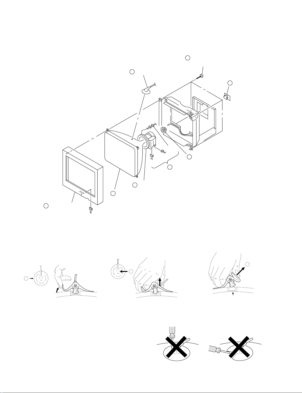
2-7. PICTURE TUBE REMOVAL
1
Anode cap
CN11
4
Four screws
(Tapping screw (5))
2pin
CN1
3
Three connectors
7
Neck assembly
2
A board
8
Deflection yoke
6
Picture tube
5
Bezel assembly
CN801
• REMOVAL OF ANODE-CAP
NOTE: Short circuit the anode of the picture tube and the anode cap to the metal chassis, CRT shield or carbon painted on the CRT, after
removing the anode.
• REMOVING PROCEDURES
c
b
a
Anode Button
1 Turn up one side of the rubber cap in
the direction indicated by the arrow a.
2 Using a thumb pull up the rubber cap
firmly in the direction indicated by the
arrow b.
• HOW TO HANDLE AN ANODE-CAP
1 Don’t scratch the surface of anode-caps with sharp shaped
material!
2 Don’t press the rubber hardly not to damage inside of anode-
caps!
A material fitting called as shatter-hook terminal is built in the
rubber.
3 Don’t turn the foot of rubber over hardly!
The shatter-hook terminal will stick out or damage the rubber.
3 When one side of the rubber cap is
separated from the anode button, the
anode-cap can be removed by turning
up the rubber cap and pulling up it in the
direction of the arrow c.
2-4
 Loading...