

Sony CPD-420GS Service manual
CPD-420GS
SERVICE MANUAL
CPD-420GS
CPD-420GS
China Model
Chassis No. SCC-L20A-A
Picture tube
Video image area
Resolution
Standard image area
Input signal
Video
Sync
SPECIFICATIONS
0.25-0.27 mm aperture grill pitch
19 inches measured diagonally
90-degree deflection Trinitron
(18" maximum viewing image)
Approx. 365 X 274 mm (w/h)
3/8
7/8
x 10
x 10
inches)
1/2
inches)
(14
Horizontal: Max. 1600 dots
Vertical: Max. 1200 lines
Approx. 352 x 264 mm (w/h)
7/8
(13
Analog RGB (75 ohms typical)
0.7 Vp-p, Positive
External HD/VD, Composite
Polarity Free TTL
Video Composite (Sync on Green)
0.3 Vp-p, Negative
D98
Power Consumption
Maximum
Nominal
Deflection frequency
AC input voltage / current
Dimensions
Mass
Design and specifications are subject to change without notice.
130 W
100 W
Horizontal: 30 to 96 KHz
Vertical: 48 to120 Hz
100 to 120 V, 50/60 Hz, 1.7A
220 to 240V, 50/60Hz, 1.2A
444 x 467 x 455 (w/h/d)
(17
Approx. 26 kg (57 lb 5 oz)
CHASSIS
1/2
1/2
x 18
x 18 inches)
— 1 —
COLOR MONITOR
CPD-420GS
(
µ
)
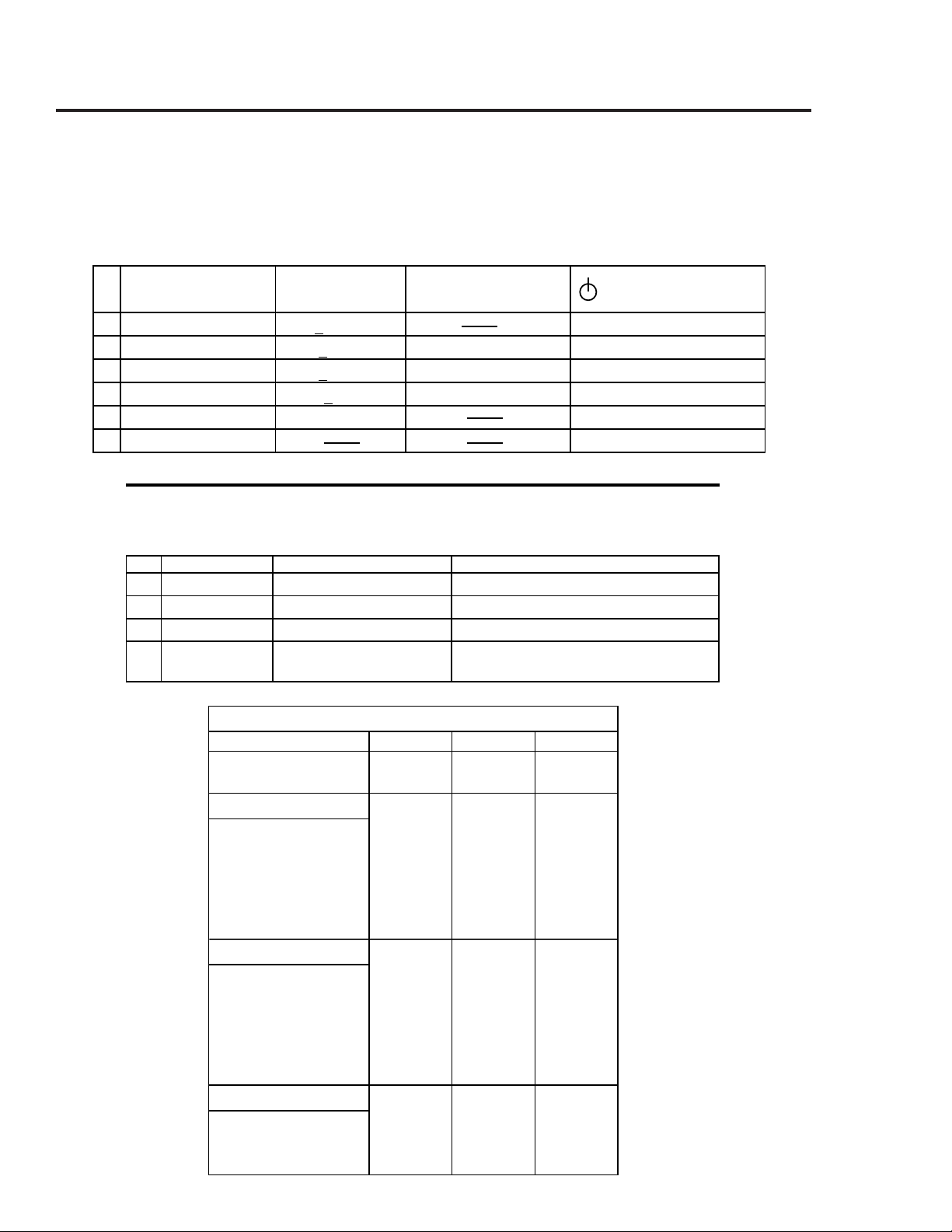
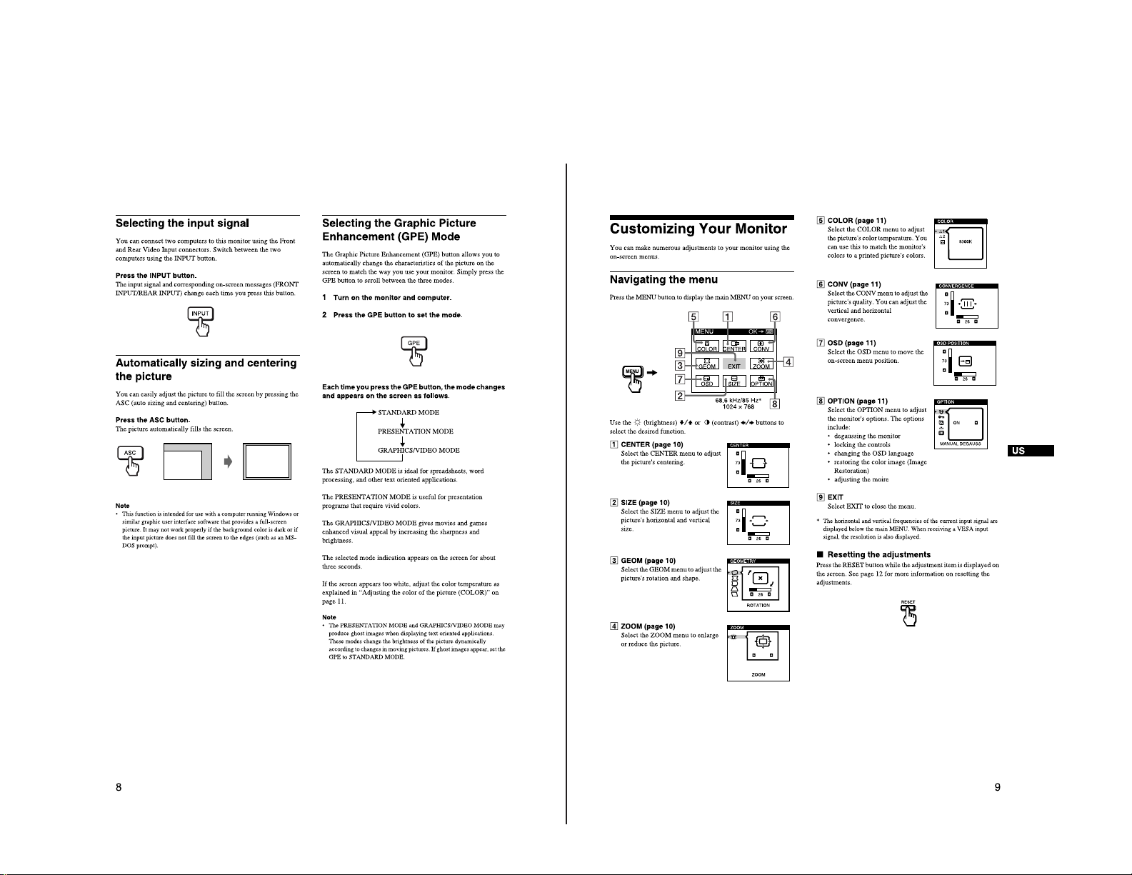
POWER SAVING FUNCTION
This monitor has three Power Saving modes.
By sensing the absence of a video signal from the
computer, it reduces power consumption as follows:
Power Required Recovery
State Consumption Time Power Indicator
1
Normal Operation
2 Standby (1st mode)
3 Suspend (2nd mode)
4 Active-off (3rd mode)
< 130W Green on
< 15W approx. 5 sec. Green and orange alternate
< 15W approx. 5 sec. Green and orange alternate
< 8W approx. 5 sec. Orange
5 Power-off 0 W Off
6 Failure modes See below
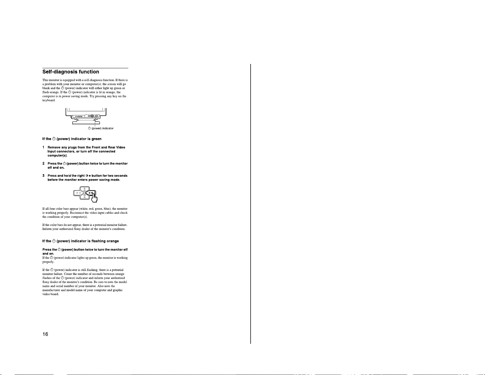
SELF DIAGNOSIS FUNCTION
When a failure occurs, the STANDBY/TIMER lamp will flash a set number of times to indicate
the possible cause of the problem. If there is more than one error, the lamp will
identify the first of the problem areas.
Status Area of Failure LED Indication
1 Failure 1 HV or B+ Orange (0.5 second)/Off (0.5 second)
2 Failure 2 H Stop, V Stop, Thermal Orange (1.5 second)/Off (0.5 second)
3 Failure 3 ABL Orange (0.5 second)/Off (1.5 second)
4 Aging/Self Test Orange (0.5 second)/Off (0.5 second)/
NOTE:
If no video signal is input to the monitor, the
"NO INPUT SIGNAL" message appears. After
about 30 seconds, the Power Saving function
automatically puts the monitor into active-off
mode and the indicator lights up orange. Once
the monitor detects horizontal and vertical sync
signals, the monitor automatically resumes
normal operation mode.
Green (0.5 second)/Off(0.5 second)
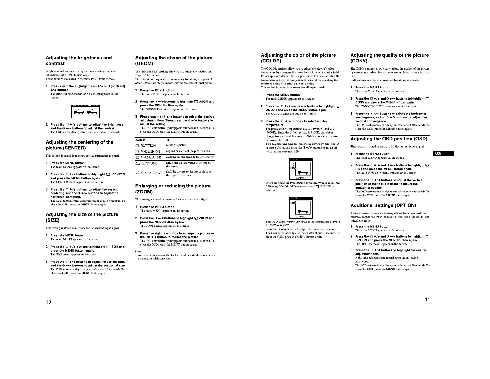
TIMING SPECIFICATION
MODE 1 2 3
Resolution (H x V) 720 X 400 1280 X 960 1600 X 1200
Dot Clock (MHz) 28.321 148.500 202.500
HORIZONTAL
Hor. Freq. (kHz) 31.468 85.938 93.750
H-Total 31.779 11.636 10.667
H-Blanking 6.356 3.017 2.765
H-Front Porch 0.636 0.431 0.316
H-Sync. 3.178 1.077 0.948
H-Back Porch 2.542 1.508 1.501
H-Active 25.423 8.62 7.901
sec
VERTICAL
Ver. Freq. (Hz) 70.084 85.002 75.000
V-Total 449 1011 1250
V-Blanking 4 9 5 1 5 0
V-Front Porch 13 1 1
V-Sync. 2 3 3
V-Back Porch 3 4 4 7 4 6
V-Active 400 960 1200
(lines)
SYNC.
Int (G) No No No
Ext (H/V)/Polarity Yes -/+ Yes +/+ Yes +/+
Ext (CS)/Polarity No No No
Int/Non Int Non Int Non Int Non Int
— 2 —
SAFETY CHECK-OUT
(US Model only)
CPD-420GS
After correcting the original service problem, perform
the following safety checks before releasing the set to the
customer:
1. Check the area of your repair for unsoldered or
poorly-soldered connections. Check the entire board
surface for solder splashes and bridges.
2. Check the interboard wiring to ensure that no wires
are “pinched” or contact high-wattage resistors.
3. Check that all control knobs, shields, covers, ground
straps, and mounting hardware have been replaced.
Be absolutely certain that you have replaced all the
insulators.
4. Look for unauthorized replacement parts,
particularly transistors, that were installed during
a previous repair. Point them out to the customer
and recommend their replacement.
5. Look for parts which, though functioning, show
obvious signs of deterioration. Point them out to
the customer and recommend their replacement.
6. Check the line cords for cracks and abrasion.
Recommend the replacement of any such line cord
to the customer.
7. Check the B+ and HV to see if they are specified
values. Make sure your instruments are accurate;
be suspicious of your HV meter if sets always have
low HV.
8. Check the antenna terminals, metal trim,
“metallized" knobs, screws, and all other exposed
metal parts for AC Leakage. Check leakage as
described below.
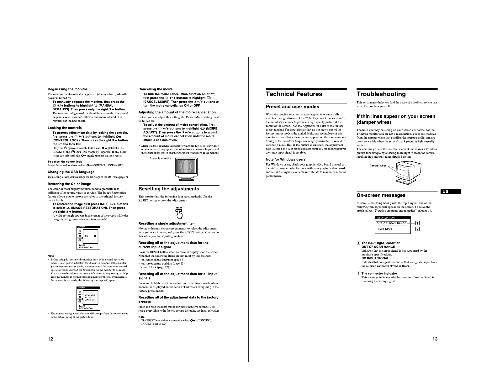
LEAKAGE TEST
The AC leakage from any exposed metal part to earth ground
and from all exposed metal parts to any exposed metal part having
a return to chassis, must not exceed 0.5 mA (500 microampere).
Leakage current can be measured by any one of three methods.
1. A commercial leakage tester, such as the Simpson 229 or
RCA WT-540A. Follow the manufacturers' instructions to
use these instructions.
2. A battery-operated AC milliammeter. The Data Precision
245 digital multimeter is suitable for this job.
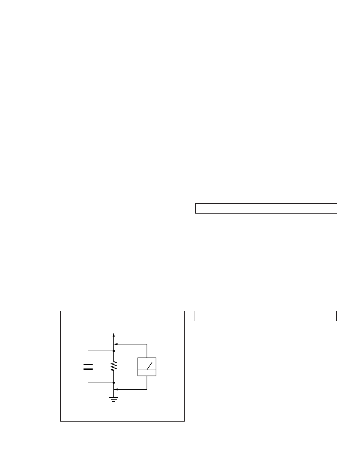
3. Measuring the voltage drop across a resistor by means of
a VOM or battery-operated AC voltmeter. The "limit"
indication is 0.75 V, so analog meters must have an accurate
low voltage scale. The Simpson's 250 and Sanwa
SH-63Trd are examples of passive VOMs that are suitable.
Nearly all battery operated digital multimeters that have a
2V AC range are suitable. (See Fig. A)
WARNING!!WARNING!!
WARNING!!
WARNING!!WARNING!!
NEVER TURN ON THE POWER IN A CONDITION IN WHICH THE
DEGAUSS COIL HAS BEEN REMOVED.
SAFETY-RELATED COMPONENT WARNING!!
COMPONENTS IDENTIFIED BY SHADING AND MARK ¡ ON
THE SCHEMATIC DIAGRAMS, EXPLODED VIEWS AND IN THE
PARTS LIST ARE CRITICAL FOR SAFE OPERATION. REPLACE
THESE COMPONENTS WITH SONY PARTS WHOSE PART
NUMBERS APPEAR AS SHOWN IN THIS MANUAL OR IN
SUPPLEMENTS PUBLISHED BY SONY . CIRCUIT ADJUSTMENTS
THAT ARE CRITICAL FOR SAFE OPERATION ARE IDENTIFIED
IN THIS MANUAL. FOLLOW THESE PROCEDURES WHENEVER
CRITICAL COMPONENTS ARE REPLACED OR IMPROPER
OPERATION IS SUSPECTED.
0.15 µF
To Exposed Metal
Parts on Set
1.5 k
Earth Ground
AVERTISSEMENT!!
NE JAMAIS METTRE SOUS TENSION QUAND LA BOBINE DE
DEMAGNETISATION EST ENLEVEE.
ATTENTION AUX COMPOSANTS RELATIFS A LA
Ω
AC
Voltmeter
(0.75 V)
LES COMPOSANTS IDENTIFIES PAR UNE TRAME ET PAR UNE
MARQUE ¡ SUR LES SCHEMAS DE PRINCIPE, LES VUES
EXPLOSEES ET LES LISTES DE PIECES SONT D'UNE
IMPORTANCE CRITIQUE POUR LA SECURITE DU
FONCTIONNEMENT. NE LES REMPLACER QUE PAR DES
COMPOSANTS SONY DONT LE NUMERO DE PIECE EST
INDIQUE DANS LE PRESENT MANUEL OU DANS DES SUPPLEMENTS PUBLIES PAR SONY. LES REGLAGES DE CIRCUIT
DONT L'IMPORTANCE EST CRITIQUE POUR LA
SECURITE DU FONCTIONNEMENT SONT IDENTIFIES DANS
LE PRESENT MANUEL. SUIVRE CES PROCEDURES LORS DE
CHAQUE REMPLACEMENT DE COMPOSANTS CRITIQUES, OU
LORSQU'UN MAUVAIS FONTIONNEMENT SUSPECTE
SECURITE!!
.
— 3 —

CPD-420GS
TABLE OF CONTENTS
Section Title Page
1. GENERAL ................................................................................... 5
2. DISASSEMBLY
2-1. Cabinet Removal ............................................................12
2-2. Service Position .............................................................. 12
2-3. D, A, H and N Board Removal......................................12
2-4. Picture Tube Removal ................................................... 13
3. SAFETY RELATED ADJUSTMENT................................. 14
4. ADJUSTMENTS ........................................................................ 15
5. DIAGRAMS
5-1. Block Diagram ................................................................19
5-2. Circuit Boards Location ................................................. 22
5-3. Schematic Diagrams and Printed Wiring Boards ...... 22
1. D Board - Schematic Diagram .................................23
2. A Board - Schematic Diagram ................................. 27
3. H Board - Schematic Diagram .................................. 31
4. N Board - Schematic Diagram .................................. 32
5-4. Semiconductors ............................................................. 35
6. EXPLODED VIEWS
6-1. Chassis ............................................................................ 37
6-2. Packing Materials .......................................................... 38
7. ELECTRICAL PARTS LIST ................................................ 39
— 4 —

— 5 —
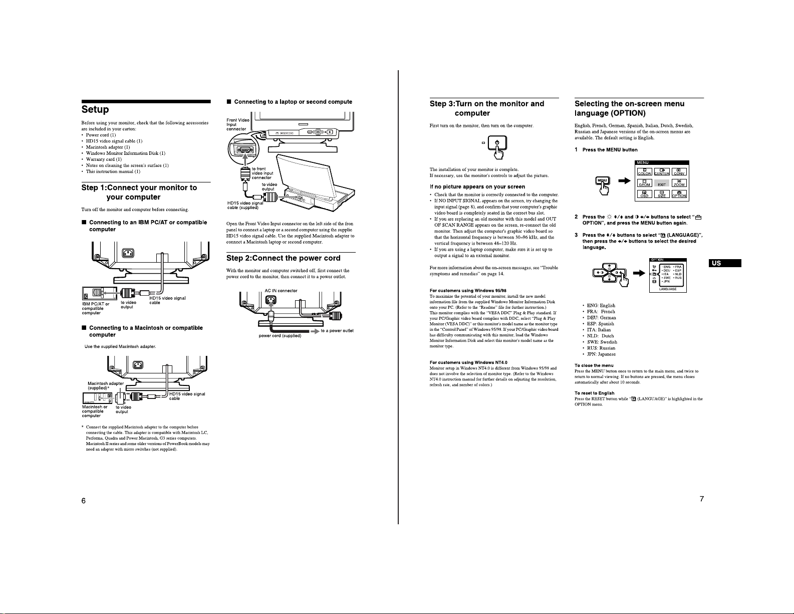
The instructions given here are partial abstracts from the Operating Instruction
Manual. The page numbers shown reflect those of the Operating Instruction Manual.
SECTION 1
GENERAL
CPD-420GS
— 6 —
CPD-420GS
— 7 —
CPD-420GS
CPD-420GS
— 8 —
— 9 —
CPD-420GS
CPD-420GS
— 10 —
— 11 —
CPD-420GS
CPD-420GS
SECTION 2
DISASSEMBLY
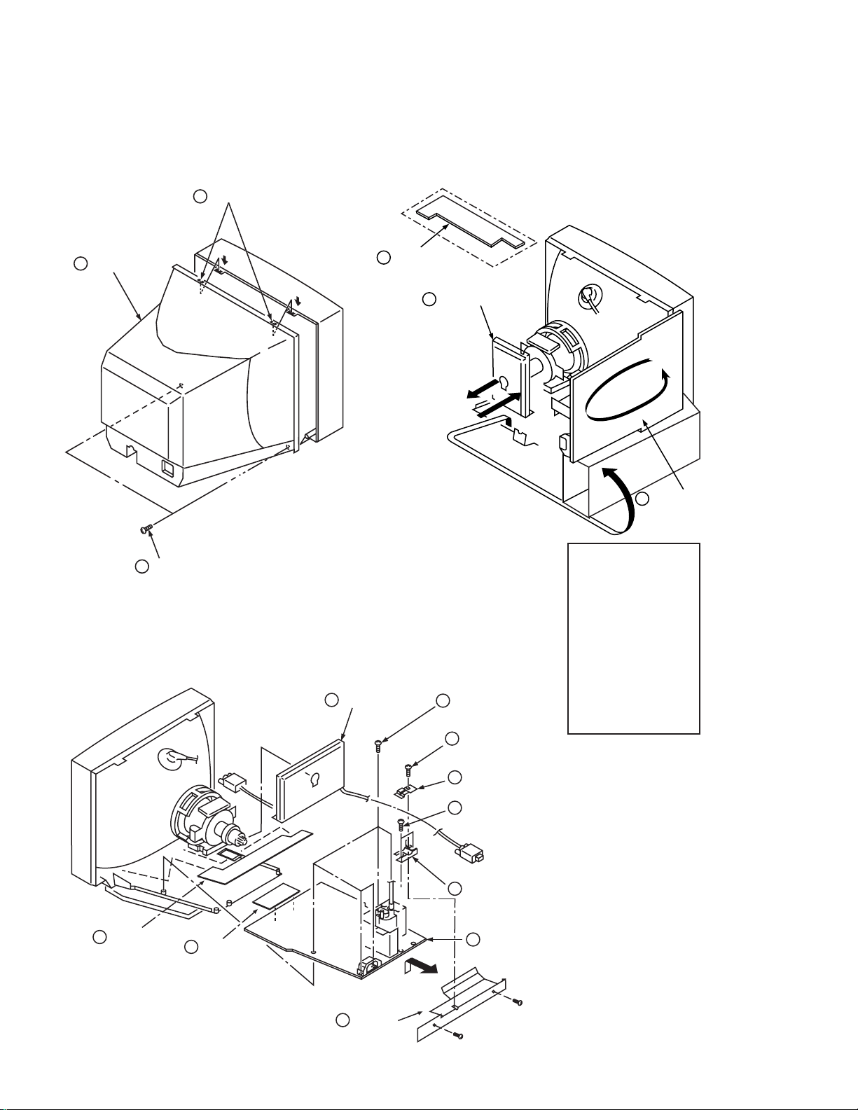
2-1. CABINET REMOVAL
Two claws
3
Cabinet
2
Two screws
1
2-2. SERVICE POSITION
PUSH
PUSH
(BVTP 4 x 16)
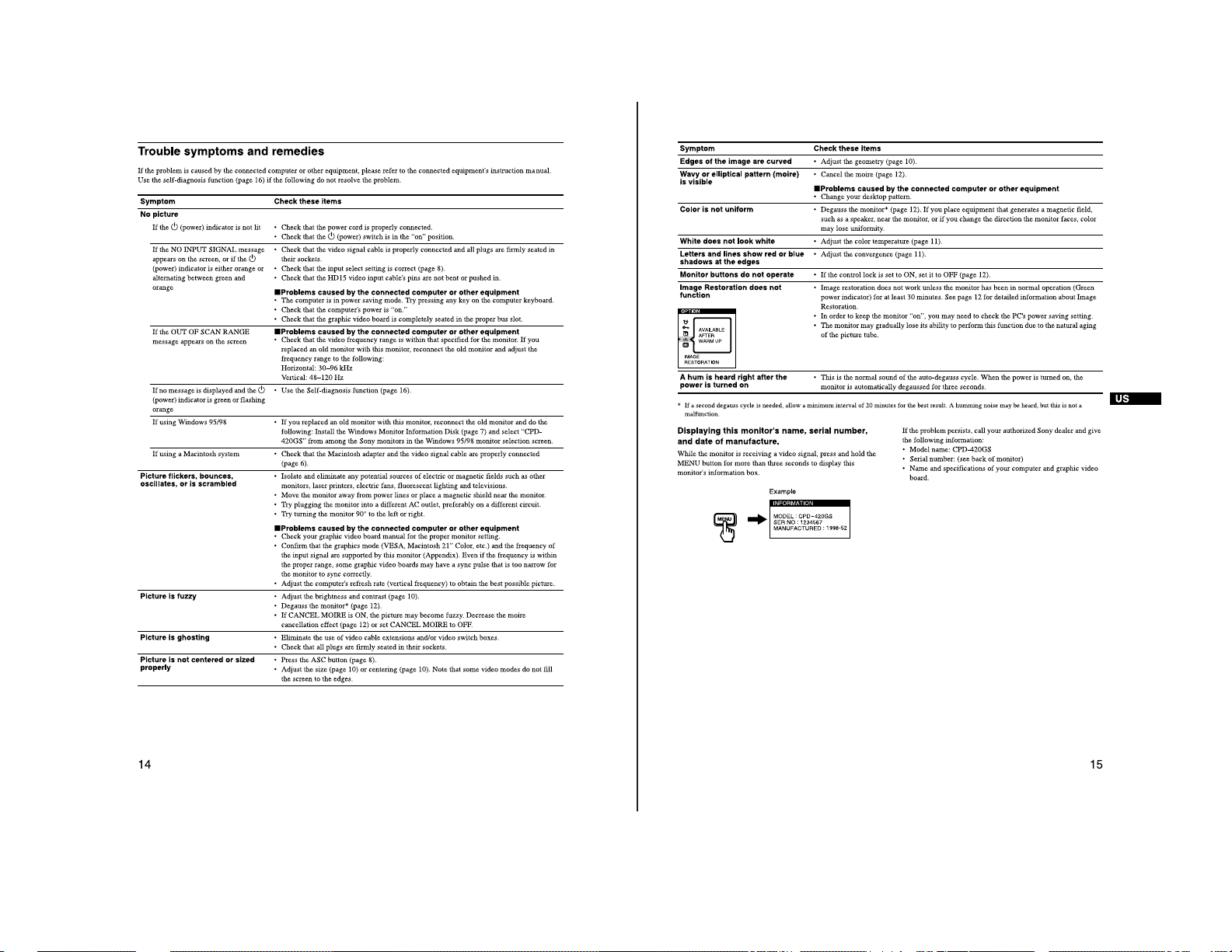
2-3. D, A, H and N BOARD REMOVAL
1
A board
1
H board
(additional board)
2
A board
3
Five screws
(BVTP 3 x 12)
4
One screw
(BVTT 4 x 8)
rotate 180º
3
D board
1 When the D-board is
placed in service
position, the Safety Earth
Wire (green and yellow
wire) is disconnected.
2 After service is
completed and the
D-board reinstalled, the
Safety Earth Wire must
be reattached to the
chassis with the proper
screw. This must be
confirmed before any
subsequent procedures
are attempted.
9
H board
2
N board
10
Holder
— 12 —
5
Two Cable stoppers
6
Two screws
(BVTP 3 x 12)
7
Cable bracket
8
D board
 Loading...