

Sony CPD-4201M Service Manual
SERVICE MANUAL
CPD-4201M
CPD-4201M
US Model
Canadian Model
Chassis No. SCC-L20B-A
Picture tube
Video image area
Resolution
Standard image area
Input signal
Video
Sync
SPECIFICATIONS
0.25-0.27 mm aperture grill pitch
19 inches measured diagonally
90-degree deflection
(18" maximum viewing image)
Approx. 365 X 274 mm (w/h)
3/8
7/8
x 10
x 10
inches)
1/2
inches)
(14
Horizontal: Max. 1600 dots
Vertical: Max. 1200 lines
Approx. 352 x 264 mm (w/h)
7/8
(13
Analog RGB (75 ohms typical)
0.7 Vp-p, Positiv e
External HD/VD, Composite
Polarity Free TTL
Video Composite (Sync on Green)
0.3 Vp-p, Negative
D98
Power Consumption
Maximum
Nominal
Deflection frequency
AC input voltage / current
Dimensions
Mass
Design and specifications are subject to change without notice.
CHASSIS
130 W
100 W
Horizontal: 30 to 96 KHz
Vertical: 48 to120 Hz
100 to 120 V, 50/60 Hz, 1.7A
220 to 240V, 50/60Hz, 1.2A
444 x 467 x 455 (w/h/d)
1/2
1/2
x 18
(17
Approx. 26 kg (57 lb 5 oz)
x 18 inches)
COLOR MONITOR
CPD-4201M
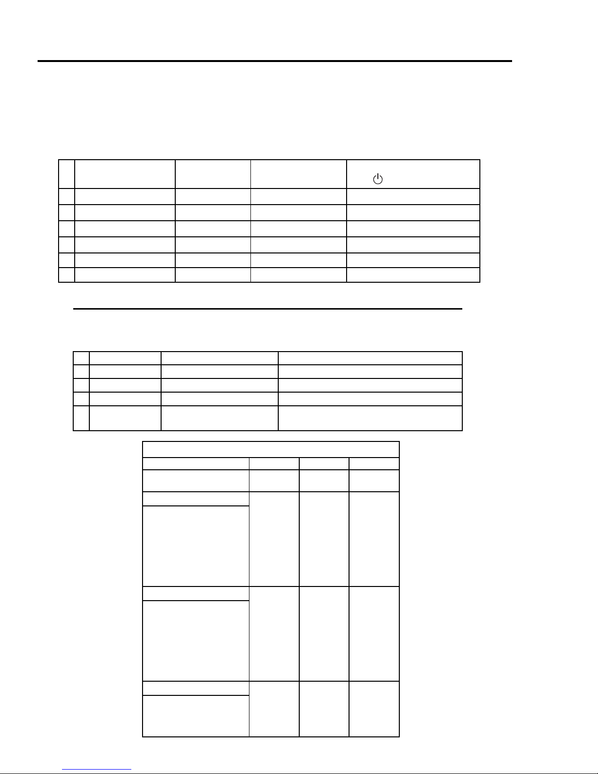
POWER SAVING FUNCTION
This monitor has three Pow er Saving modes.
By sensing the absence of a video signal from the
computer, it reduces power consumption as follows:
NOTE:
If no video signal is input to the monitor, the
"NO INPUT SIGNAL" message appears. After about
30 seconds, the Po wer Saving function automatically
puts the monitor into active-off mode and the indicator
lights up orange. Once the monitor detects horizontal
and vertical sync signals, the monitor automatically
resumes normal operation mode.
State
1 Normal Operation
2 Standby (1st m ode)
3 Suspend (2nd mode)
4 Active-off (3rd mode)
Power
Consumption
≤
125W
≤
15W
≤
15W
≤
8W
Required Recovery
Time Power Indicator
—Greenon
approx. 3 sec. Green and orange alternate
approx. 3 sec. Green and orange alternate
approx. 10 sec. Orange
5 Power-off 0.2W — Off
6 Failure modes — — See below
SELF DIAGNOSIS FUNCTION
When a failure occurs, the STANDBY/TIMER lamp will flash a set number of times to indicate
the possible cause of the problem. If there is more than one error, the lamp will identify
the first of the problem areas.
Status Area of Failure LED Indication
1 Failure 1 HV or B+ Orange (0.5 second)/Off (0.5 second)
2 Failure 2 H Stop, V Stop, Thermal Orange (1.5 second)/Off (0.5 second)
3 Failure 3 ABL Orange (0.5 second)/Off (1.5 second)
4 Aging/Self Test Orange (0.5 second)/Off (0.5 second)/
Green (0.5 second)/Off (0.5 second)
TIMING SPECIFICATION
MODE 123
Resolution (H x V)
Dot Clock (MHz)
HORIZONTAL
Hor. Freq.(kHz)
H-Total
H-Blanking
H-Front Porc h
H-Sync.
H-Back Porch
H-Active
(µsec )
VERTICAL
Ver. Freq. (Hz)
V-Total
V-Blanking
V-Front Porch
V-Sync.
V-Back Porch
V-Active
(lines)
SYNC.
Int (G)
Ext (H/V)/Polarity
Ext (CS)/Polarity
Int/Non Int
720 x 400
28.321
31.468
31.779
6.356
0.636
3.178
2.542
25.423
70.084
449
49
13
34
400
No
Yes -/+
No
Non Int
1280 x 1024
135.000
2
79.976
12.504
3.022
0.119
1.067
1.837
9.481
75.025
1066
42
38
1024
No
Yes +/+
No
Non Int
1600 x 1200
202.500
1
3
93.750
10.667
2.765
0.316
0.948
1.501
7.901
75.000
1250
50
1
3
46
1200
No
Yes +/+
No
Non Int
— 2 —
SAFETY CHECK-OUT
CPD-4201M
After correcting the original service problem,
perform the following safety checks before releasing the
set to the customer:
1.Check the area of your repair for unsoldered or poorlysoldered connections. Check the entire board surface for
solder splashes and bridges.
2.Check the interboard wiring to ensure that no wires are
“pinched” or contact high-wattage resistors.
3.Check that all control knobs, shields, covers, ground
straps, and mounting hardware have been replaced. Be
absolutely certain that you have replaced all the
insulators.
4.Look for unauthorized replacement parts, particularly
transistors, that were installed during a previous repair.
Point them out to the customer and recommend their
replacement.
5.Look for parts which, though functioning, show obvious
signs of deterioration. Point them out to the customer
and recommend their replacement.
6.Check the line cords for cracks and abrasion. Recommend
the replacement of any such line cord to the customer.
7.Check the B+ and HV to see if they are specified values.
Make sure your instruments are accurate; be suspicious
of your HV meter if sets always have low HV.
8.Check the antenna terminals, metal trim, “metallized"
knobs, screws, and all other exposed metal parts for AC
Leakage. Check leakage as described below.
LEAKAGE TEST
The AC leakage from any exposed metal part to earth ground
and from all exposed metal parts to any exposed metal part having
a return to chassis, must not exceed 0.5 mA (500 microampere).
Leakage current can be measured by any one of three methods.
1.A commercial leakage tester, such as the Simpson 229 or RCA
WT-540A. Follow the manufacturers' instructions to use these
instructions.
2.A battery-operated AC milliammeter. The Data Precision 245
digital multimeter is suitable for this job.
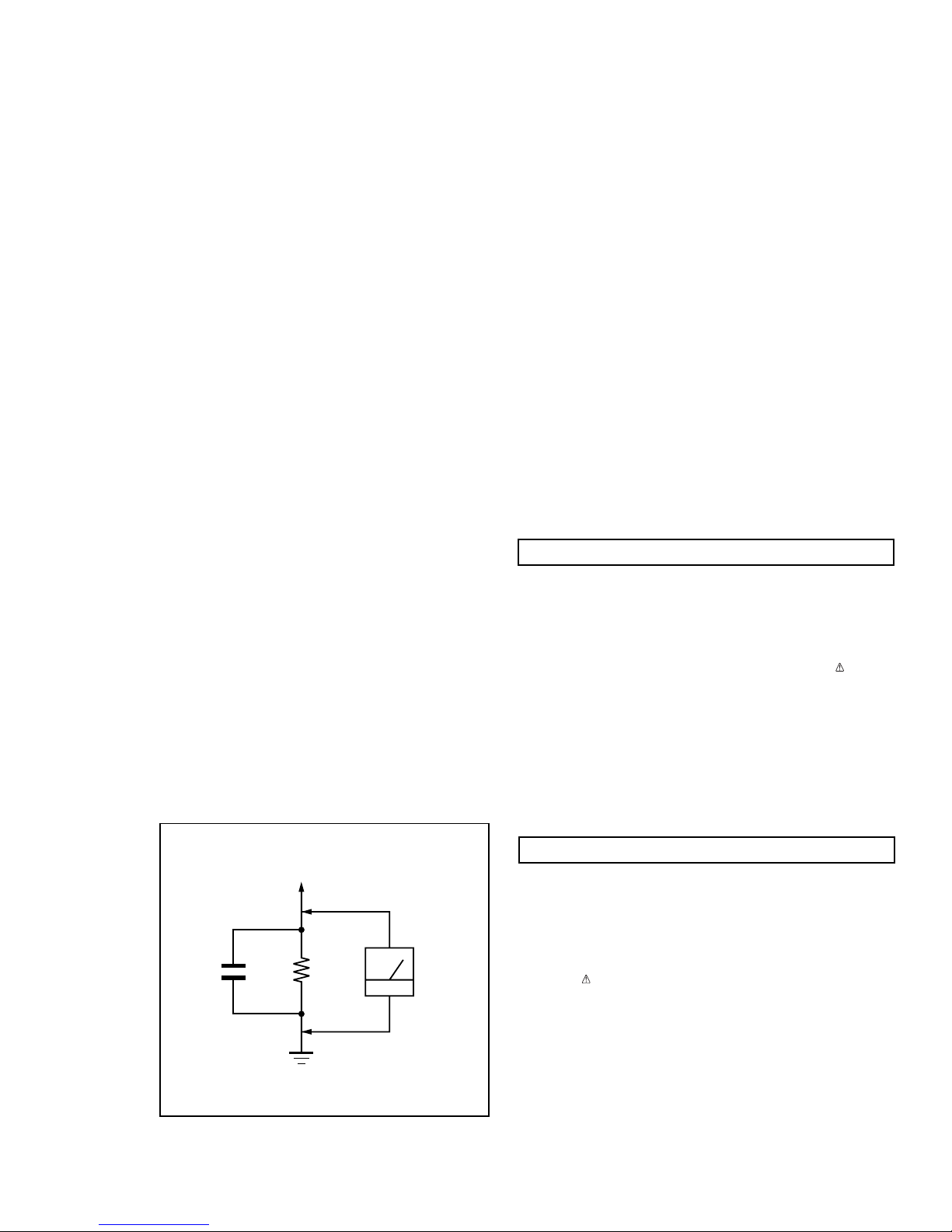
3.Measuring the voltage drop across a resistor by means of a
VOM or battery-operated AC voltmeter. The "limit"
indication is 0.75 V, so analog meters must have an accurate
low voltage scale. The Simpson's 250 and Sanwa SH-63Trd
are examples of passive VOMs that are suitable. Nearly all
battery operated digital multimeters that have a 2V AC range
are suitable. (See Figure A)
WARNING!!
NEVER TURN ON THE POWER IN A CONDITION IN WHICH THE
DEGAUSS COIL HAS BEEN REMOVED.
SAFETY-RELATED COMPONENT WARNING!!
COMPONENTS IDENTIFIED BY SHADING AND MARK ON THE
SCHEMATIC DIAGRAMS, EXPLODED VIEWS AND IN THE PARTS
LIST ARE CRITICAL FOR SAFE OPERATION. REPLACE THESE
COMPONENTS WITH SONY PARTS WHOSE PART NUMBERS
APPEAR AS SHOWN IN THIS MANUAL OR IN SUPPLEMENTS
PUBLISHED BY SONY. CIRCUIT ADJUSTMENTS THAT ARE
CRITICAL FOR SAFE OPERATION ARE IDENTIFIED IN THIS
MANUAL. FOLLOW THESE PROCEDURES WHENEVER CRITICAL
COMPONENTS ARE REPLACED OR IMPROPER OPERATION IS
SUSPECTED.
To Exposed Metal
Parts on Set
0.15 µF
1.5 k
Figure A
Ω
Earth Ground
AC
Voltmeter
(0.75 V)
AVERTISSEMENT!!
NE JAMAIS METTRE SOUS TENSION QUAND LA BOBINE DE
DEMAGNETISATION EST ENLEVEE.
ATTENTION AUX COMPOSANTS RELATIFS A LA SECURITE!!
LES COMPOSANTS IDENTIFIES PAR UNE TRAME ET PAR UNE
MARQUE SUR LES SCHEMAS DE PRINCIPE, LES VUES
EXPLOSEES ET LES LISTES DE PIECES SONT D'UNE
IMPORTANCE CRITIQUE POUR LA SECURITE DU
FONCTIONNEMENT. NE LES REMPLACER QUE PAR DES
COMPOSANTS SONY DONT LE NUMERO DE PIECE EST
INDIQUE DANS LE PRESENT MANUEL OU DANS DES
SUPPLEMENTS PUBLIES PAR SONY. LES REGLAGES DE
CIRCUIT DONT L'IMPORTANCE EST CRITIQUE POUR LA
SECURITE DU FONCTIONNEMENT SONT IDENTIFIES DANS LE
PRESENT MANUEL. SUIVRE CES PROCEDURES LORS DE
CHAQUE REMPLACEMENT DE COMPOSANTS CRITIQUES, OU
LORSQU'UN MAUVAIS FONTIONNEMENT SUSPECTE.
— 3 —

CPD-4201M
TABLE OF CONTENTS
Section Title Page
1. GENERAL ............................................................................................ 5
2. DISASSEMBLY
2-1. Cabinet Removal ................................................................. 11
2-2. Service Position ................................................................... 11
2-3. D, A, H and N Board Removal.......................................... 11
2-4. Picture Tube Removal ........................................................ 12
3. SAFETY RELATED ADJUSTMENT.................................... 1 3
4. ADJUSTMENTS ............................................................................. 14
5. DIAGRAMS
5-1. Block Diagram ..................................................................... 19
5-2. Circuit Boards Location ..................................................... 22
5-3. Schematic Diagrams and Printed Wiring Boards ......... 22
1. D Board - Schematic Diagram..................................... 23
2. A Board - Schematic Diagram..................................... 27
3. N Board - Schematic Diagram .................................... 31
4. H Board - Schematic Diagram .................................... 35
5-4. Semiconductors ................................................................... 37
6. EXPLODED VIEWS
6-1. Chassis .................................................................................. 39
6-2. Packing Materials ................................................................ 40
7. ELECTRICAL PARTS LIST ..................................................... 41
— 4 —
— 5 —
CPD-4201M
SECTION 1
GENERAL
The instructions given here are partial abstracts from the Operating Instruction
Manual. The page numbers shown reflect those of the Operating Instruction Manual.
3
Getting Started
US
Table of Contents
Precautions. . . . . . . . . . . . . . . . . . . . . . . . . . . . . . . . . . 3
Setup. . . . . . . . . . . . . . . . . . . . . . . . . . . . . . . . . . . . . . . 4
Parts and Controls . . . . . . . . . . . . . . . . . . . . . . . . . . . . 4
The OSD (On-screen Display) System. . . . . . . . . . . . . 6
Resetting the adjustments . . . . . . . . . . . . . . . . . . . . . 10
Specifications . . . . . . . . . . . . . . . . . . . . . . . . . . . . . . . 11
Monitor Information. . . . . . . . . . . . . . . . . . . . . . . . . . . 11
Power Saving Function and LED Indicators. . . . . . . . 11
If thin lines appear on your screen (damper wires). . . 11
Warning Messages. . . . . . . . . . . . . . . . . . . . . . . . . . . 12
Troubleshooting . . . . . . . . . . . . . . . . . . . . . . . . . . . . . 12
Precautions
Do not install the monitor in the following places:
• on surfaces (rugs, blankets, etc.) or near materials (curtains,
draperies) that may block the ventilation holes
• near heat sources such as radiators or air ducts, or in a place
subject to direct sunlight
• in a place subject to severe temperature changes
• in a place subject to mechanical vibration or shock
• on an unstable surface
• near equipment which generates magnetism, such as a
transformer or high voltage power lines
• near or on an electrically charged metal surface
• Clean the screen with a soft cloth. If you use a glass cleaning
liquid, do not use any type of cleaner containing an anti-static
solution or similar additive as this may scratch the screen’s
coating.
• Do not rub, touch, or tap the surface of the screen with sharp or
abrasive items such as a ball point pen or screwdriver. This type
of contact may result in a scratched picture tube.
• Clean the cabinet, panel and controls with a soft cloth lightly
moistened with a mild detergent solution. Do no t use a ny typ e of
abrasive pad, scouring powder or solvent, such as alcohol or
benzene.
When you transport this monitor for repair or shipment, use the
original carton and packing materials.
• Use the supplied power cord. If you use a different power cord,
be sure that it is compatible with your local power supply.
For the customers in the US
If you do not use the appropriate cord, this monitor will not
conform to mandatory FCC Standards.
• Before disconnecting the power cord, wait at least 30 seconds
after turning off the power to allow the static electricity on the
screen’s surface to discharge.
• After the power is turned on, the screen is demagnetized
(degaussed) for about 3 seconds. This generates a strong
magnetic field around the screen, which may affect data stored on
magnetic tapes and disks placed near the monitor. Be sure to keep
magnetic recording equipment, tapes and disks away from the
monitor.
Installation
Maintenance
Transportation
Warning on power Connection
The equipment should be installed near an easily accessible
outlet.
Example of plug types
for 100 to 120 V AC for 200 to 240 V AC
4
Getting Started
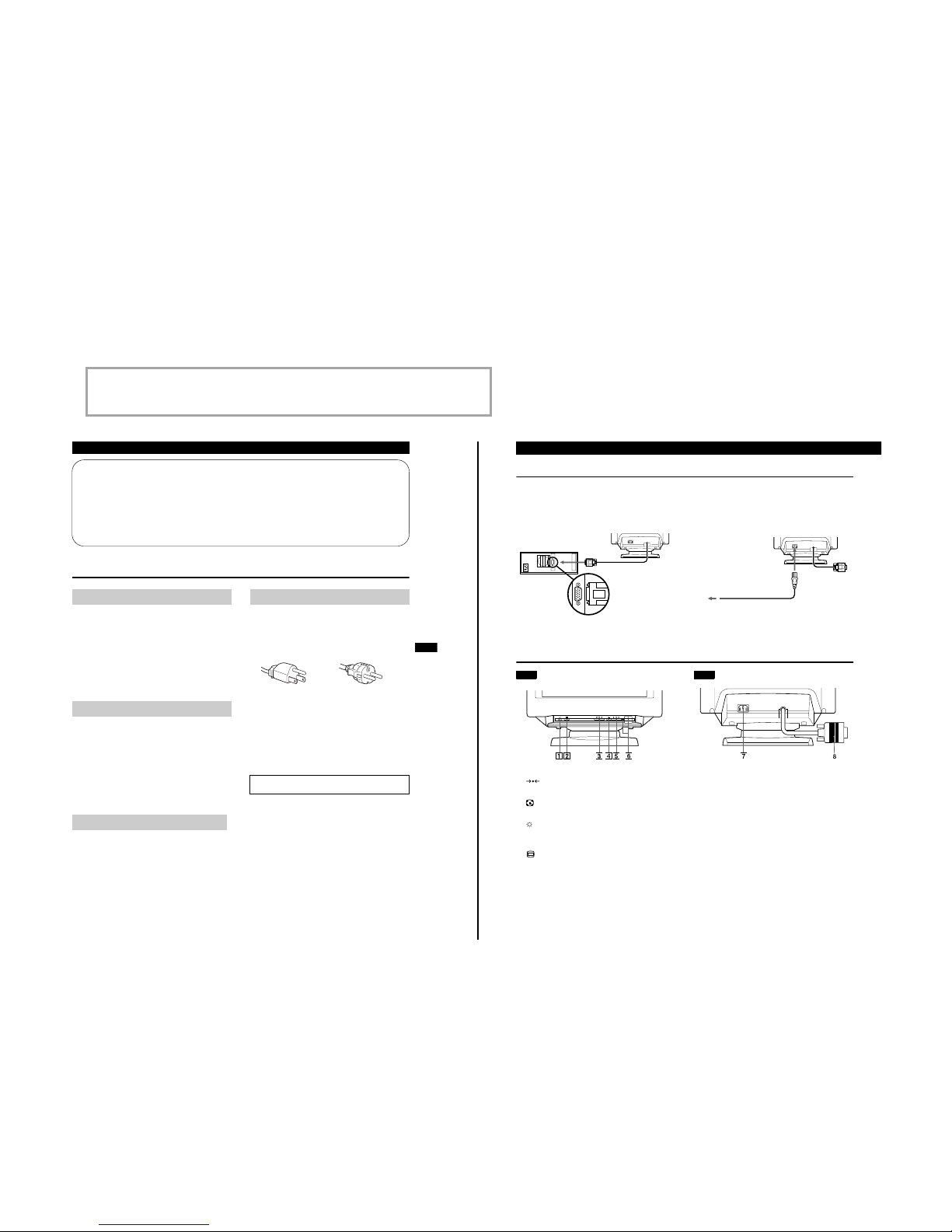
Setup
Connect the monitor to your computer system.
This monitor will sync to platforms running at horizontal frequencies between 30 and 96 kHz.
Step 1
Make sure the compuer system is switched off and attach
the video signal cable to the video output of the computer.
Step 2
Make sure the compuer is switched off and attach the
power cord the monitor. Then, attach the other end of the
power cord to a power outlet.
Step 3
Switch on the monitor and computer.
Step 4
Adjust the user controls according to your personal
preference.
Installation is complete.
Parts and Controls
1 (RESET) button (pages 6, 10)
Resets the adjustments to the factory settings.
2 Auto Sizing and Centering button (page 5)
Automatically adjusts the picture size and position.
3 (BRIGHTNESS) (v/V) buttons (page 5)
Adjust the picture brightness.
Operate as the (v/V) buttons when adjusting other items.
4 (MENU) button (page 6)
Displays the MENU OSD.
5 6 (CONTRAST) (B/b) buttons (page 5)
Adjust the contrast.
Operate as the (B/b) buttons when adjusting other items.
6 1 (POWER) switch an d indicator
Turns the monitor on and off.
The indicator lights up green when the monitor is on, and lights
up green and orange when the monitor is in Power Saving
mode.
7 AC IN connector
Provides AC power to the monitor.
8 Video input connector (HD15) (page 5)
Inputs RGB video signals and SYNC signals.
Computer
to the video output
to a power outlet
Power cord
Front
Rear
— 6 —
CPD-4201M
5
Getting Started Customizing Your Monitor
US
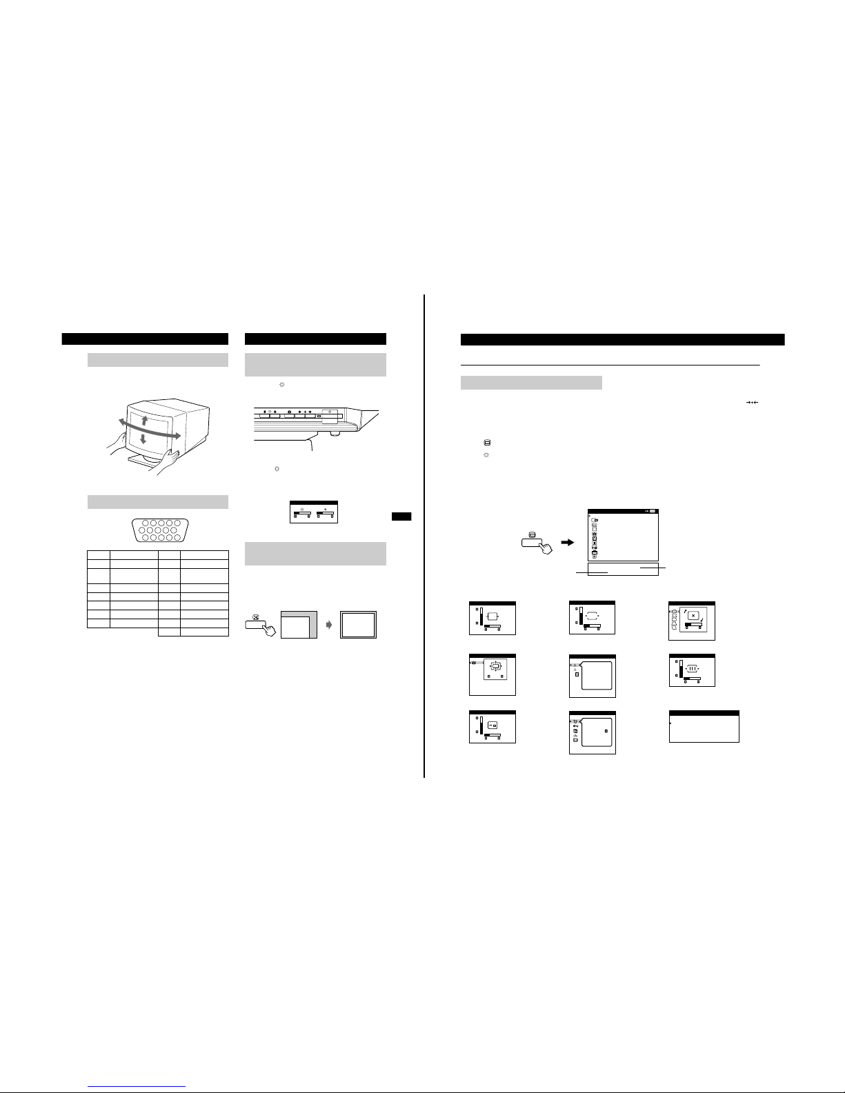
This monitor can be adjusted within the angles shown below. To
turn the monitor vertically or horizontally, hold it at the bottom with
both hands.
1
Press the (BRIGHTNESS)
v/V
or 6 (CONTRAST)
B/b
buttons.
The BRIGHTNESS/CONTRAST OSD appeears.
2
To adjust the brightness.
Press the (BRIGHTNESS) v/V buttons.
To adjust the contrast.
Press the 6 (CONTRAST) B/b buttons.
You can easily adjust the picture to fill the screen by pressing the
Auto Sizing and Centering button.
Press the Auto Sizing and Centering button.
The picture automatically fills the screen.
Note
This function is intended for use with a computer running Windows or
similar graphic user interface software that provides a full-screen picture. It
may not work properly if the background color is dark or if the input picture
does not fill the screen to the edges (such as an MS-DOS prompt).
Use of the Tilt/Swivel
Video Connector
Pin No. Signal Pin No. Signal
1 Red 8 Blue Ground
2 Green (Composite
Sync on Green)
9 Not used (no pin)
3Blue 10Ground
4Ground 11Ground
5 CPU Snense 12 SDA (serial data)
6 Red Ground 13 Horizontal Sync
7 Green Ground 14 Vertical Sync
15 SCL (serial clock)
90°
5°
90°
15°
1234
5
987
10
11 12 13 14 15
6
Adjusting the Picture Brightness
and Contrast
Automatically Sizing and
Centering the Picture
BRIGHTNESS/CONTRAST
26 26
6
Customizing Your Monitor
The OSD (On-screen Display) System
You can adjust most of the monitor’s settings using the OSDs (Onscreen Display). All of the OSDs in this illustration are described on
the following pages in order. You can access any of these OSDs
from the MENU OSD. To adjust monitor settings using the OSDs,
follow the steps below:
Basic controls:
• Use the (MENU) button to display the MENU OSD and to
select menu items.
• Use the (BRIGHTNESS) v/V buttons to highlight menu
items and to adjust settings.
To adjust the monitor settings:
1
Press the MENU button to display the MENU OSD.
2
Highlight the desired OSD using the BRIGHTNESS buttons and
press the MENU button again.
3
If necessary, use the BRIGHTNESS buttons to select a specific
item.
4
Adjust the monitor setting using the BRIGHTNESS and
CONTRAST buttons.
• To reset the current item to its original setting, press the
(RESET) button while the item’s adjustment OSD is displayed.
5
When you finish adjusting the setting, press the MENU button to
return to the MENU OSD.
Press the MENU button twice to return to normal viewing.
• Resetting: If you press the RESET button while an OSD is
displayed, only the current adjustment item is reset. For
additional information on using the reset function, see the
“Resetting the Adjustments” section on page 10.
• The eac h of th e adj ustment’s OSD automatically disappears
after 30 seconds.
Introducing the OSD System
OK
MENU
MENU
EXIT
CENTER
SIZE
GEOMETRY
ZOOM
COLOR
CONVERGENCE
OSD POSITION
OPTION
GRAPHIC ENHANCEMENT
80.0kHz/ 75Hz
1280 X 1024
Horizontal/Vertical
frequencies for
current input signal
Resolution for current
input signal
1
CENTER
2
SIZE
3
GEOMETRY
4
ZOOM
5
COLOR
6
CONVERGENCE
7
OSD POSITION
8
OPTION
9 GRAPHIC ENHANCEMENT
CENTER
26
73
SIZE
26
73
ROTATION
GEOMETRY
26
ZOOM
ZOOM
COLOR
1
2
9300K
CONVERGENCE
26
73
OSD POSITION
26
73
MANUAL DEGAUSS
ON
OPTION
GRAPHIC ENHANCEMENT
STANDARD MODE
GRAPHICS/VIDEO MODE
PRESENTATION MODE

— 7 —
CPD-4201M
7
Customizing Your Monitor
US
1 Adjusting the centering of the
picture (CENTER)
This setting is stored in memory for the current input signal.
1
Press the MENU button.
The main MENU appears on the screen.
2
Press the
v/V
buttons to highlight CENTER
and press the MENU button again.
The CENTER menu appears on the screen.
3
Press the
v/V
buttons to adjust the vertical
centering, and the 6
B/b
buttons to adjust the
horizontal centering.
The OSD automatically disappears after about 30 seconds. To
close the OSD, press the MENU button again.
2 Adjusting the size of the picture
(SIZE)
This setting is stored in memory for the current input signal.
1
Press the MENU button.
The main MENU appears on the screen.
2
Press the
v/V
buttons to highlight SIZE and
press the MENU button again.
The SIZE menu appears on the screen.
3
Press the
v/V
buttons to adjust the vertical size,
and the 6
B/b
buttons to adjust the horizontal size.
The OSD automatically disappears after about 30 seconds. To
close the OSD, press the MENU button again.
3 Adjusting the shape of the
picture (GEOM)
The GEOMETRY settings allow you to adjust the rotation and
shape of the picture.
The rotation setting is stored in memory for all input signals. All
other settings are stored in memory for the current input signal.
1
Press the MENU button.
The main MENU appears on the screen.
2
Press the
v/V buttons to highlight GEOM and
press the MENU button again.
The GEOMETRY menu appears on the screen.
3
First press the v/V buttons to select the desired
adjustment item. Then press the 6 B/b buttons to
adjust the setting.
The OSD automatically disappears after about 30 seconds. To
close the OSD, press the MENU button again.
4
Enlarging or reducing the picture
(ZOOM)
This setting is stored in memory for the current input signal.
1
Press the MENU button.
The main MENU appears on the screen.
2
Press the v/V buttons to highlight ZOOM and
press the MENU button again.
The ZOOM menu appears on the screen.
3
Press the right 6 b button to enlarge the picture or the
left 6 B button to reduce the picture.
The OSD automatically disappears after about 30 seconds. To
close the OSD, press the MENU button again.
Note
Adjustment stops when either the horizontal or vertical size reaches its
maximum or minimum value.
Adjusting the Settings
Select To
ROTATION
rotate the picture
PINCUSHION
expand or contract the picture sides
PIN BALANCE
shift the picture sides to the left or right
KEYSTONE
adjust the picture width at the top of the
screen
KEY BALANCE
shift the picture to the left or right at the
top of the screen
8
Customizing Your Monitor
5 Adjusting the color of the picture
(COLOR)
The COLOR settings allow you to adjust the picture’s color
temperature by changing the color level of the white color field.
Colors appear reddish if the temperature is low, and bluish if the
temperature is high. This adjustment is useful for matching the
monitor’s colors to a printed picture’s colors.
This setting is stored in memory for all input signals.
1
Press the MENU button.
The main MENU appears on the screen.
2
Press the
v/V
buttons to highlight COLOR and
press the MENU button again.
The COLOR menu appears on the screen.
3
Press the
v/V
buttons to select a color
temperature.
The preset color temperatures are 1 (9300K) and 2
(5000K). Since the default setting is 9300K, the whites change
from a bluish hue to a reddish hue as the temperature is lowered
to 5000K.
You can also fine tune the color temperature by selecting in
step 2 above, and using the 6 B/b buttons to adjust the color
temperature manually.
If you are using the Presentation or Graphic/Video mode, the
following COLOR OSD appears when “ COLOR” is
selected.
This OSD allows you to adjust the color temperature between
11,000K to 9,300K.
Press the 6 B/b buttons to adjust the color temperature.
The OSD automatically disappears after about 30 seconds. To
close the OSD, press the MENU button again.
6 Adjusting the quality of the
picture (CONV)
The CONV settings allow you to adjust the quality of the picture by
eliminating red or blue shadows around letters, characters and lines.
Both settings are stored in memory for all input signals.
1
Press the MENU button.
The main MENU appears on the screen.
2
Press the
v/V
buttons to highlight CONV and
press the MENU button again.
The CONVERGENCE menu appears on the screen.
3
Press the 6
B/b
buttons to adjust the horizontal
convergence, or the
v/V
buttons to adjust the
vertical convergence.
The OSD automatically disappears after about 30 seconds. To
close the OSD, press the MENU button again.
7 Adjusting the OSD position
(OSD)
This setting is stored in memory for the current input signal.
1
Press the MENU button.
The main MENU appears on the screen.
2
Press the
v/V
buttons to highlight OSD and
press the MENU button again.
The OSD POSITION menu appears on the screen.
3
Press the
v/V
buttons to adjust the vertical
position or the 6
B/b
buttons to adjust the horizontal
position.
The OSD automatically disappears after about 30 seconds. To
close the OSD, press the MENU button again.
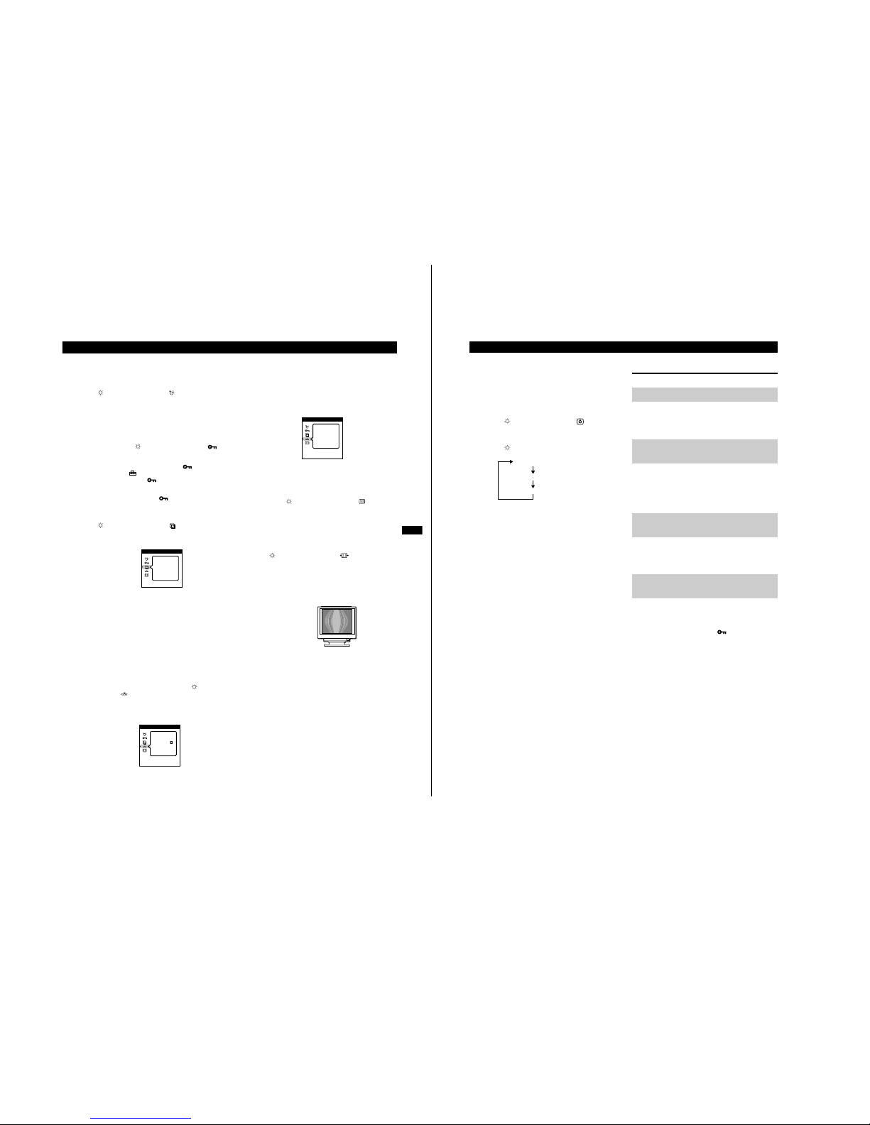
8 Additional settings (OPTION)
You can manually degauss (demagnetize) the screen, lock the
controls, change the OSD language, restore the color image, and
cancel the moire.
1
Press the MENU button.
The main MENU appears on the screen.
2
Press the
v/V
buttons to highlight OPTION and
press the MENU button again.
The OPTION menu appears on the screen.
3
Press the
v/V
buttons to highlight the desired
adjustment item.
Adjust the selected item according to the following instructions.
The OSD automatically disappears after about 30 seconds. To
close the OSD, press the MENU button again.
VARIABLE
COLOR
1
2
VARIABLE
COLOR
— 8 —
CPD-4201M
9
Customizing Your Monitor
US
Degaussing the monitor
The monitor is automatically degaussed (demagnetized) when the
power is turned on.
To manually degauss the monitor, first press the
v/V
buttons to highlight (MANUAL DEGAUSS).
Then press only the right 6 b button.
The monitor is degaussed for about three seconds. If a second
degauss cycle is needed, allow a minimum interval of 20
minutes for the best result.
Locking the controls
To protect adjustment data by locking the controls,
first press the
v/V
buttons to highlight
(CONTROL LOCK). Then press the right 6 b button to
turn the lock ON.
Only the 1 (power) switch, EXIT and (CONTROL
LOCK) of the OPTION menu will operate. If any other
items are selected, the mark appears on the screen.
To cancel the control lock
Repeat the procedure above and set (CONTROL LOCK) to OFF.
Changing the OSD language
To change the language of the OSD, first press the
v/V
buttons to highlight (LANGU AGE). Then
press the 6
B/b
buttons to select the desired
language.
• ENG: English
• FRA: French
•DEU: German
• ESP: Spanish
•ITA: Italian
• NLD: Dutch
• SWE: Swedish
• RUS: Russian
• JPN: Japanese
Restoring the Color Image
The color of most display monitors tend to gradually lose brilliance
after several years of service. The Color Return featur e al lo ws you
to restore the color to the original factory preset levels.
To restore the image, first press the
v/V
buttons
to select (COLOR RETURN). Then press the right
6 b
button.
A white rectangle appears in the center of the screen while the
image is being restored (about two seconds).
Note
• Before using this feature, the monitor must be in normal operation mode
(Green power indicator) for at least 30 minutes. If the monitor goes into
power saving mode, you must return the monitor to normal operation
mode and wait for 30 minutes for the monitor to be ready. You may need
to adjust your computer’s power saving settings to help keep the monitor
in normal operation mode for the full 30 minutes. If the monitor is not
ready, the following message will appear.
• The monitor may gradually lose its ability to perform this function due to
the natural aging of the picture tube.
Cancelling the moire
To turn the moire cancellation function on or off, first
press the
v/V
buttons to highlight (CANCEL
MOIRE). Then press the 6
B/b
buttons to turn the
moire cancellation ON or OFF.
Adjusting the amount of the moire cancellation
Before you can adjust this setting, the Cancel Moire setting must be
turned ON.
To adjust the amount of moire cancellation, first press
the
v/V
buttons to highlight (MOIRE ADJUST).
Then press the 6
B/b
buttons to adjust the amount of
moire cancellation until the moire effect is at a
minimum.
* Moire is a type of natural interference which produces soft, wavy lines on
your screen. It may appear due to interference between the pattern of the
picture on the screen and the phosphor pitch pattern of the monitor.
• ENG
• DEU
• ITA
• SWE
• JPN
LANGUAGE
• FRA
• ESP
• NLD
• RUS
OPTION
COLOR
RETURN
OPTION
ON
COLOR
RETURN
AVAILABLE
AFTER
WARM UP
OPTION
Example of moire
10
Customizing Your Monitor
9 Using the GRAPHIC
ENHANCEMENT OSD
This setting is stored in memory for the current input signal.
1
Press the MENU button.
The main MENU appears on the screen.
2
Press the
v/V
buttons to highlight GRAPHIC
ENHANCEMENT and press the MENU button again.
GRAPHIC ENHANCEMENT OSD appears.
3
Press the v button to select the mode.
The STANDARD MODE is ideal for spreadsheets, word
processing, and other text oriented applications.
The PRESENTATION MODE is useful for presentation programs
that require vivid colors.
The GRAPHICS/VIDEO MODE gives movies and games
enhanced visual appeal by increasing the sharpness and brightness.
The selected mode indication appears on the screen for about three
seconds.
If the screen appears too white, adjust the color temperature
(see “Adjusting the color of the picture (COLOR)” on page8).
Note
The PRESENTATION MODE and GRAPHICS/VIDEO MODE may
produce ghost images when displaying text oriented applications. These
modes change the brightness of the picture dynamically according to
changes in moving pictures. If ghost images appear, set the Video
Enhancement Mode to STANDARD MODE.
Resetting the adjustments
Navigate through the on-screen menus to select the adjustment item
you want to reset, and press the RESET button. You can do this
while you are adjusting an item.
Press the RESET button when no menu is displayed on the screen.
Note that the following items are not reset by this method:
• on-screen menu language (page 9)
• on-screen menu position (page 8)
• control lock (page 9)
Press and hold the reset button for more than two seconds when no
menu is displayed on the screen. This resets everything to the
factory preset mode.
Press and hold the reset button for more than five seconds. This resets
everything to the factory presets including the input selection.
Note
The RESET button does not function when
(CONTOL LOCK) is
set to ON.
STANDARD MODE
PRESENTATION MODE
GRAPHICS/VIDEO MODE
Resetting a specific adjustment
Resetting all of the adjustments
for the current input signal
Resetting all of the adjustments
for all input signals
Resetting all of the adjustment
data to the factory presets
— 9 —
CPD-4201M
11
Technical Features
US
Specifications
Picture tube 0.25 – 0.27 mm aperture grill pit ch,
19 inches measured diagonally,
90 degree deflection
Viewable image size Approx. 365 × 274 mm (w/h)
(14
3
/8 × 10 7/8 in.)
18.0" viewing image
Resolution
Horizontal Max. 1600 dots
Vertical Max. 1200 lines
Display picture size Approx. 352 × 264 mm (w/h)
(13
7
/8 × 10 1/2 in.)
Deflection frequency
Horizontal 30 to 96 kHz
Vertical 48 to 120 Hz
AC input voltage/current 100 to 240 V, 50/60 Hz, 1.7 A
220 to 240 V, 50/60 Hz, 1.2 A
Dimensions
Approx. 444 × 467 × 455 mm (w/h/d)
(17 1/2 × 18 1/2 × 18 in.)
Mass Approx. 26 kg (57 lb 5 oz)
Plug and Play DDC/DDC2B, DDC2Bi, GTF
Design and specifications are subject to change without notice.
Monitor Information
You can display the model name, serial number and year of
manufacture using the INFORMATION OSD.
Press and hold the MENU button for 5 seconds.
The INFORMATION OSD appears.
The INFORMATION OSD includes the model name, serial number
and year of manufacture.
The OSD automatically disappears aftrer about 30 seconds.
Power Saving Function and
LED Indicators
This monitor has three Power Saving modes. By sensing the
absence of a video signal from the computer, it reduces power
consumption as follows.
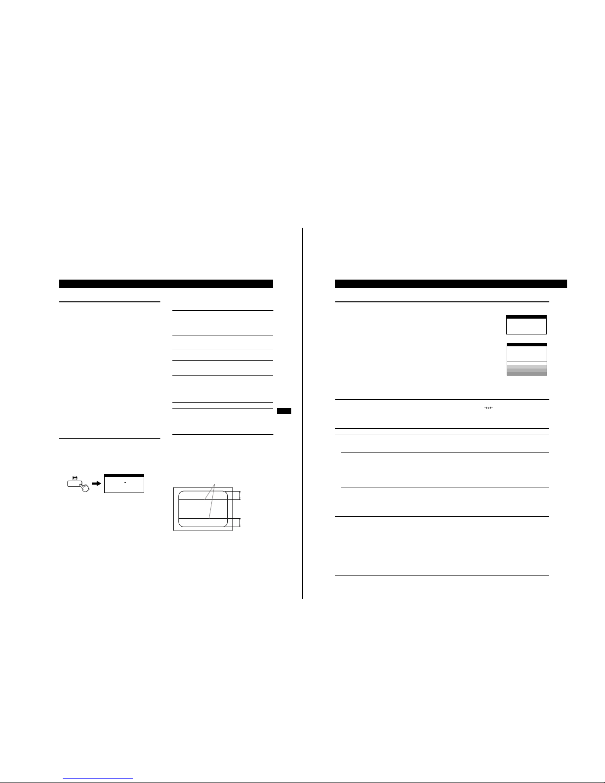
If thin lines appear on your
screen (damper wires)
The lines you may be seeing on your screen are normal for the
Trinitron monitor and are not a malfunction. These are shadows
from the damper wires that stabilize the aperture grille, and are most
noticeable when the screen’s background is light (usually white).
The aperture grille is the essential element that makes a Trinitron
picture tube unique by allowing more light to reach the screen,
resulting in a brighter, more detailed picture.
SER NO : 1234567
MODEL : CPD VX900T
MANUFACTURED
: 1998-53
INFORMATION
Power
consumption
mode
Power
consumption
Recovery
time
1
indicator
1Normal
operation
≤ 125 W — Green
2Standby
(1st mode)
≤ 15 W Approx.
3 sec.
Green and
orange
alternate
3Standby
(2nd mode)
≤ 15 W Approx.
3 sec.
Green and
orange
alternate
4 Active-off
(3rd mode)
≤ 8 W Approx.
10 sec.
Orange
5Power-off 0.2 W — Off
Damper wires
Approx. 7 cm
Approx. 7 cm
12
Additional Information
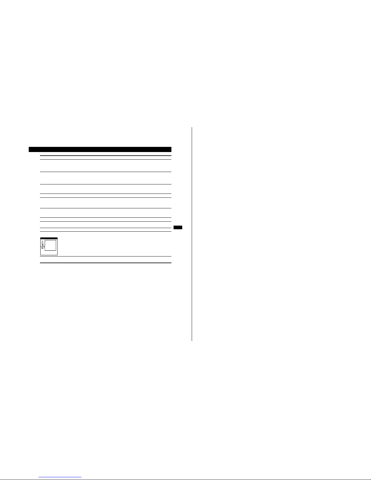
Warning Messages
If there is something wrong with the input signal, one of the following messages appears.
To solve these problems, see the “Troubleshooting” section below.
Troubleshooting
Before calling service technician regarding picture quality related questions, please press and hold (RESET) button for 6 seconds. This
resets everything to the factory presets including the input selection.
If the problem is caused by the connected computer or other equipment, please refer to the connected equipment’s instruction manual.
1
Out of Scan Range
This message indicates that the current input signal is not appropriate by the monitor’s specificatons.
2
Check signal cable (self test pattern)
This message indicates that there are no input signal is received, or the video cable is not connected.
Symptom Check these items
No picture
If the 1 (power) indicator is not lit • Check that the power cord is properly connected.
• Check that the 1 (power) switch is in the “on” position.
If the CHECK SIGNAL CABLE
message appears on the screen, or if
the 1 (power) indicator is either
orange or alternating between green
and orange
• Check that the video signal cable is properly connected and all plugs are firmly seated in
their sockets.
• Check that the HD15 video input cable’s pins are not bent or pushed in.
xProblems caused by the connected computer or other equipment
• The computer is in power saving mode. Try pressing any key on the computer keyboard.
• Check that the computer’s power is “on.”
• Check that the graphic video board is completely seated in the proper bus slot.
If the OUT OF SCAN RANGE
message appears on the screen
xProblems caused by the connected computer or other equipment
• Check that the video frequency range is within that specified for the monitor. If you replaced
an old monitor with this monitor, reconnect the old monitor and adjust the frequency range to
the following:
Horizontal: 30–96 kHz
Vertical: 48–120 Hz
Picture flickers, bounces,
oscillates, or is scrambled
• Isolate and eliminate any potential sources of electric or magnetic fields such as other
monitors, laser printers, electric fans, fluorescent lighting and televisions.
• Move the monitor away from power lines or place a magnetic shield near the monitor.
• Try plugging the monitor into a different AC outlet, preferably on a different circuit.
• Try turning the monitor 90° to the left or right.
xProblems caused by the connected computer or other equipment
• Check your graphic video board manual for the proper monitor setting.
• Confirm that the graphics mode (VESA, VGA, etc.) and the frequency of the input signal are
supported by this monitor (Appendix). Even if the frequency is within the proper range,
some graphic video boards may have a sync pulse that is too narrow for the monitor to sync
correctly.
• Adjust the computer’s refresh rate (vertical frequency) to obtain the best possible picture.
INFORMATION
MONITOR IS WORKING
OUT OF SCAN RANGE
INFORMATION
MONITOR IS WORKING
CHECK SIGNAL CABLE
RED
GREEN
BLUE
WHITE
— 10 —
CPD-4201M
13
Additional Information
US
* If a second degauss cycle is needed, allow a minimum interval of 20 minutes for the best result. A h umming n oise m ay be h eard, but this is not a malfunction.
Picture is fuzzy • Adjust the brightness and contrast (page 5).
• Degauss the monitor* (page 9).
• If CANCEL MOIRE is ON, the picture may become fuzzy. Decrease the moire cancellation
effect (page 9) or set CANCEL MOIRE to OFF.
Picture is ghosting • Eliminate the use of video cable extensions and/or video switch boxes.
• Check that all plugs are firmly seated in their sockets.
• Check the Graphic Enhancement mode, if you are using a still picture application such as
Excel.
Picture is not centered or sized
properly
• Press the Auto Sizing and Centering button (page 5).
• Adjust the size (page 7) or centering (page 7). Note that some video modes do not fil l the
screen to the edges.
Edges of the image are curved • Adjust the geometry (page 7).
Wavy or elliptical pattern (moire) is
visible
• Cancel the moire (page 9).
x
Problems caused by the connected computer or other equipment
• Change your desktop pattern.
Color is not uniform • Degauss the monitor* (page 9). If you place equipment that generates a magnetic field, such
as a speaker, near the monitor, or if you change the direction the monitor faces, color may
lose uniformity.
White does not look white • Adjust the color temperature (page 8).
Letters and lines show red or blue
shadows at the edges
• Adjust the convergence (page 8).
Monitor buttons do not operate • If the control lock is set to ON, set it to OFF (page 9).
COLOR RETURN does not function • COLOR RETURN does not work unless the monitor has been in normal operation (Green
power indicator) for at least 30 minutes. See page 9 for detailed information about Image
Restoration.
• In order to keep the monitor “on”, you may need to check the PC’s power saving setting.
• The monitor may gradually lose its ability to perform this function due to the natural aging of
the picture tube.
A hum is heard right after the
power is turned on
• This is the normal sound of the auto-degauss cycle. When the power is turned on, the monitor
is automatically degaussed for three seconds.
Symptom Check these items
COLOR
RETURN
AVAILABLE
AFTER
WARM UP
OPTION
SECTION 2
DISASSEMBLY
CPD-4201M
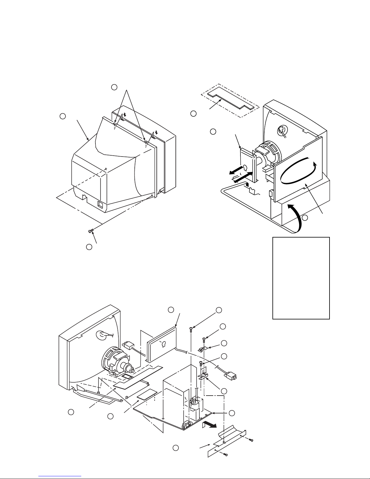
2-1. CABINET REMOVAL
Two claws
3
Cabinet
2
Two screws
1
2-2. SERVICE POSITION
PUSH
PUSH
(BVTP 4 x 16)
2-3. D, A, H and N BOARD REMOVAL
1
A board
1
H board
(additional board)
2
A board
3
Five screws
(BVTP 3 x 12)
rotate 180º
3
D board
1 When the D-board is
placed in service
position, the Safety Earth
Wire (green and yellow
wire) is disconnected.
2 After service is
completed and the
D-board reinstalled, the
Safety Earth Wire must
be reattached to the
chassis with the proper
screw. This must be
confirmed before any
subsequent procedures
are attempted.
9
H board
2
N board
10
Holder
— 11 —
4
One screw
(BVTT 4 x 8)
5
Two Cable stoppers
6
Two screws
(BVTP 3 x 12)
7
Cable bracket
8
D board
CPD-4201M
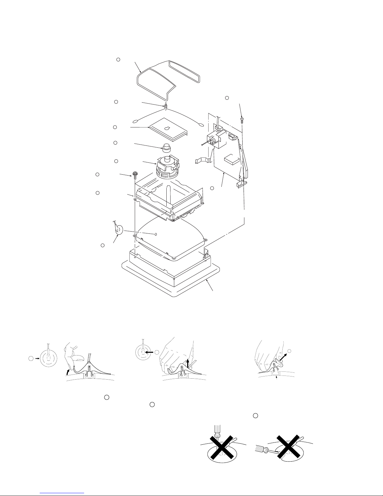
Anode Button
c
2-4. PICTURE TUBE REMOVAL
Demagnetization coil
7
Tension spring
6
A board
5
Neck assy
4
Deflection yoke
3
Four screws
(Tapping screw 5)
Picture tube shield
2
8
9
Two screws
(BVTP 4 x 16)
10
Stand assy
(D board)
1
Anode cap
Cushion
REMOVAL OF THE ANODE-CAP
NOTE: Short circuit the anode of the picture tube and the anode cap to the metal chassis, CRT shield or carbon painted on the CRT, after
removing the anode.
REMOVAL PROCEDURES
a
1 Turn up one side of the rubber cap in
the direction indicated by arrow a .
2 Use your thumb to pull the rubber cap
firmly in the direction indicated by
arrow b .
HOW TO HANDLE AN ANODE-CAP
1 Do not use sharp objects which may cause damage to the surface
of the anode-cap.
2 Do not squeeze the rubber covering too hard to avoid damaging
the anode-cap. A material fitting called a shatter-hook terminal is
built into the rubber.
3 Do not force turn the foot of the rubber cover. This may cause the
shatter-hook terminal to protrude and damage the rubber.
b
3 When one side of the rubber cap sepa-
rates from the anode button, the anodecap can be removed by turning the rubber cap and pulling it in the direction of
arrow c .
— 12 —
SECTION 3
SAFETY RELATED ADJUSTMENT
CPD-4201M
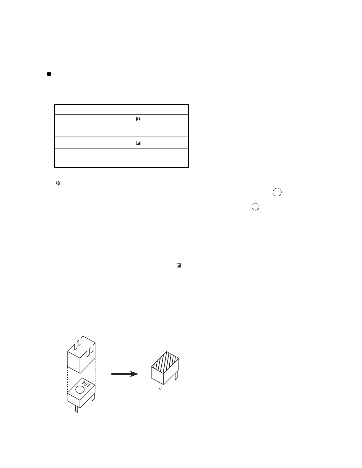
When replacing parts shown in the table below, the
following operational checks must be performed as a
safety precaution against X-ray emissions from the unit.
D - BOARD
Part Replaced ( )
Part Replaced ( )
T901, R903, IC805, R921, R922, R812, D908, IC605,
R913, R914, D802, D909
Allow the unit to warm up for one minute prior to
checking the following conditions:
RV904
a) HV Regulator Check
1) Input white cross hatch signal. (fH = 94 kHz)
2) Minimum CONT and BRT controls.
3) Cut off Screen VR (G2).
4) Input voltage: 120 ± 2 VAC
5) Confirm that the voltage is within the voltage range
shown below.
Standard voltage: 27.0KV ± 0.2KV
6) When replacing components identified by
sure to recheck the High Voltage.
7) Verify the High Voltage as shown above (27.0KV ± 0.2KV)
is within specification. If not, set H. SIZE data at
minimum (-127) and then adjust RV904 on "D" Board.
8) After adjusting the High Voltage within specification,
put the RV cover on RV904 as shown below and apply
sufficient amount of RTV around RV904.
, make
b) HV Hold-Down Check
1) Using an external DC Power supply, apply the voltage
shown below between cathode of D908 on "D" Board
and GND, and confirm that the HV Hold-Down circuit
works. (Raster disappears)
Apply DC Voltage: 21.5 ± 0.5 VDC
Check Condition
• Input voltage : 120 ± 2 VAC
• Input signal : (fH = 94 kHz), White Cross Hatch
• Controls : CONT (max) & BRT (center)
• B+ Voltage : 181 ± 4.0 VDC
c) Beam Protector Check (Software logic)
1) Using an external current source, apply 1.30
± 0.05 mA between pin 11 of FBT
(T501) and GND, and confirm that the voltage
at CN801 pin 1 is 2.25 VDC or less.
Check Condition
• Input voltage : 120 ± 2 VAC
• Input signal : (fH = 94 kHz), White Cross Hatch
• Controls : CONT (max) & BRT (center)
d) B± MAX. Check
1) Input white cross hatch (fH = 94 kHz) signal.
2) CONT (max) & BRT (center)
3) Input voltage: 120 ± 2 VAC
Note: Use NF p owe r s u p ply or m ake sure that
distortion factor is 3% or less.
4) Confirm that the voltage is within the voltage
range shown below.
Standard voltage: 181 ± 4.0 VDC
RV904
— 13 —
CPD-4201M
SECTION 4
ADJUSTMENTS
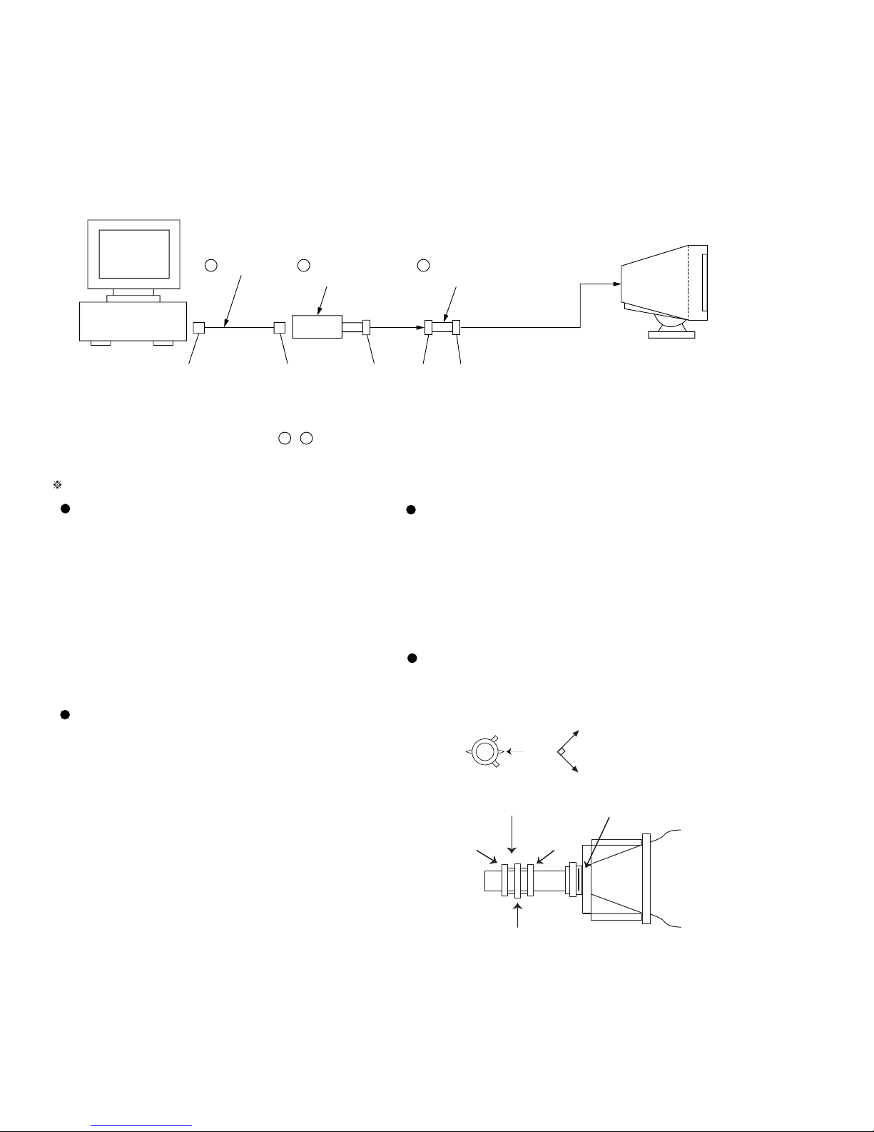
Connect the communication cable of the connector located on the D board on the monitor. Run the service software and
then follow the instructions.
IBM AT Computer
as a Jig
1-690-391-21
1
D-sub
(9 Pin [female])
*The parts above ( ~ ) are necessary for DAS adjustment.
mini Din
(8Pin)
1
A-1500-819-A
2
Interface Unit
3
4 Pin
3-702-691-01
3
Connector Attachment
To BUS CONNECTOR
4 Pin 4 Pin
Allow a 30 minute warm-up period prior to making the following adjustments:
Landing Rough Adjustment
1. Enter the full white signal.
2. Adjust the contrast to the maximum.
3. Input full green signal.
4. Moving the DY backward, and adjust coarsely the purity
magnet sothat a green raster positions in the center of
screen.
Convergence Rough Adjustment
1. All digital convergence data should be zero by MCP.
2. Enter the white crosshatch signal.
3. Adjust roughly the horizontal and vertical
convergence at four-pole magnet.
4. Adjust roughly HMC and VMC at six-pole
magnet.
5. Moving the DY forward, adjust so that an entire screen
becomes pure green.
6. Adjust the tilt of DY, and tighten lightly with a clamp.
Convergence Fine Adjustment
Set DY four-pole magnet to mechanical center
before adjustment.
• Landing Fine Adjustment
This should be prime mode.
1. Place the set in the Helmholtz coil.
2. Enter a green signal only.
3. Degauss the entire screen with hand-degausser.
Then auto-degauss it.
4. Attach a wobbling coil to the specified position of CRT
Neck Assy
neck.
5. Attach a landing adjuster sensor on the CRT.
6-pole Mg
6. Using a landing checker, adjust the DY position, purity,
tilt of DY.
7. Clamp the DY screw.
Clamping torque: 22
±
2 kgcm (2.2 ± 0.2 N.m)
4-pole Mg
Set the
finger
P.S. Mg
Mechanical
Center
XBV
DY
CRT
— 14 —
CPD-4201M
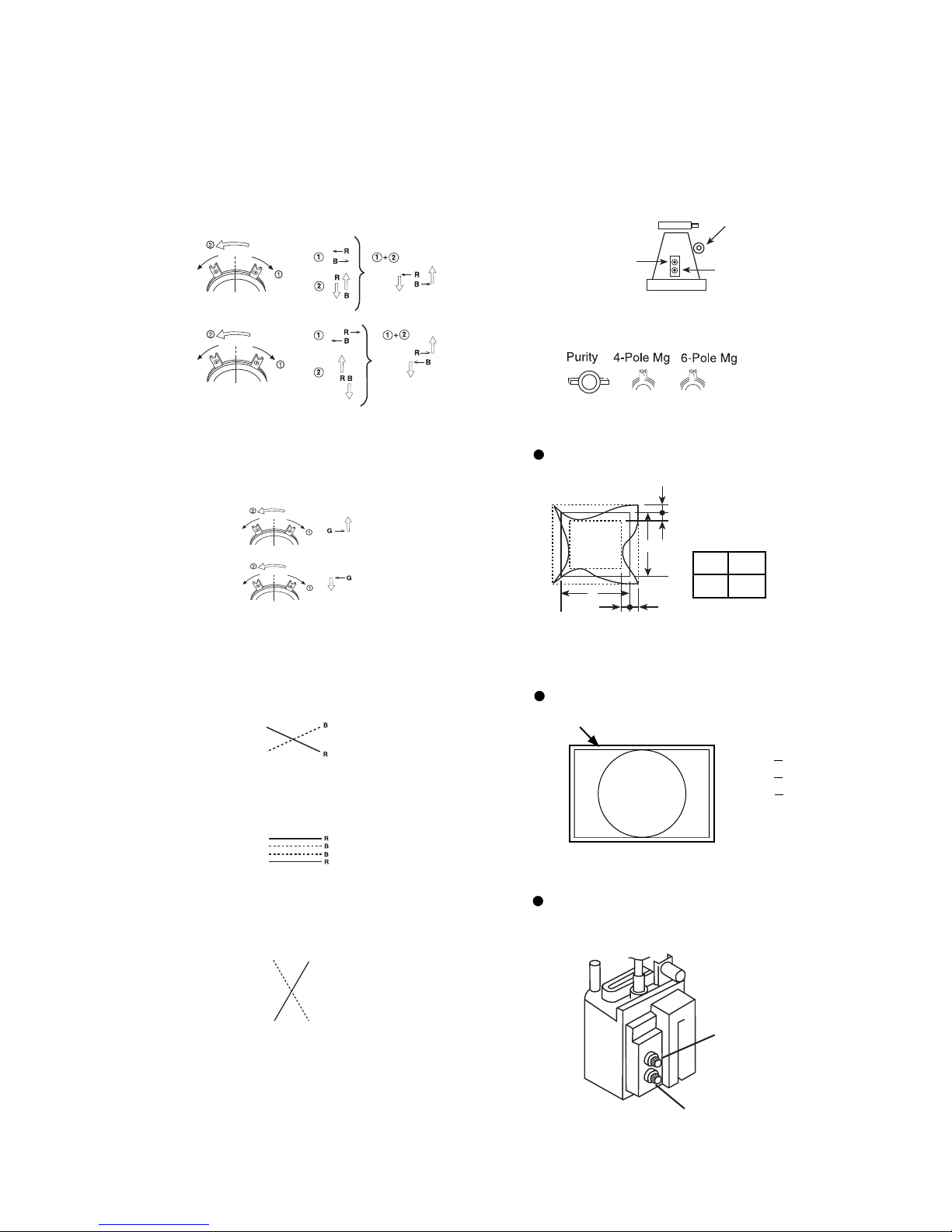
1. Receive R.B. cross-hatch.
2. Adjust H.STAT and V.STAT at four-pole magnet.
4 Pole Magnet
3. Receive White cross-hatch.
4. Adjust HMC and VMC at six-pole magnet.
< 6 Pole Magnet>
5. Receive R.B. cross-hatch.
6. Adjust H.TILT by swinging the DY neck right and left.
7. Adjust XCV with XCV core.
10. Paint lock the four-pole and six-pole Mg.
VR Adjustment on DY
XCV
YCH
TLV
Zero Position NECK Ass'y
Vertical and Horizontal Position and Size
Specification
a
a < 3.0 mm
b < 3.0 mm
a
A
A B
B
bb
264 352
XCV movement
8. Adjust V.TILT with TLV VR.
TLV movement
9. Adjust Y.CROSS with YCH VR.
YCH movement
RB
Convergence Specification
C
A
Horizontal and Vertical
B
A < 0.25mm
B < 0.30mm
C < 0.35mm
Focus adjustment
Adjust focus (V) and focus (H) for optimum focus.
Focus (V)
FBT
Focus (H)
— 15 —
 Loading...